EP3199415A1 - Systems and methods for solenoid state determination - Google Patents
Systems and methods for solenoid state determination Download PDFInfo
- Publication number
- EP3199415A1 EP3199415A1 EP17152780.7A EP17152780A EP3199415A1 EP 3199415 A1 EP3199415 A1 EP 3199415A1 EP 17152780 A EP17152780 A EP 17152780A EP 3199415 A1 EP3199415 A1 EP 3199415A1
- Authority
- EP
- European Patent Office
- Prior art keywords
- solenoid
- current
- state
- control unit
- brake
- Prior art date
- Legal status (The legal status is an assumption and is not a legal conclusion. Google has not performed a legal analysis and makes no representation as to the accuracy of the status listed.)
- Granted
Links
Images



Classifications
-
- H—ELECTRICITY
- H01—ELECTRIC ELEMENTS
- H01F—MAGNETS; INDUCTANCES; TRANSFORMERS; SELECTION OF MATERIALS FOR THEIR MAGNETIC PROPERTIES
- H01F7/00—Magnets
- H01F7/06—Electromagnets; Actuators including electromagnets
- H01F7/08—Electromagnets; Actuators including electromagnets with armatures
- H01F7/18—Circuit arrangements for obtaining desired operating characteristics, e.g. for slow operation, for sequential energisation of windings, for high-speed energisation of windings
- H01F7/1844—Monitoring or fail-safe circuits
-
- H—ELECTRICITY
- H01—ELECTRIC ELEMENTS
- H01F—MAGNETS; INDUCTANCES; TRANSFORMERS; SELECTION OF MATERIALS FOR THEIR MAGNETIC PROPERTIES
- H01F7/00—Magnets
- H01F7/06—Electromagnets; Actuators including electromagnets
- H01F7/064—Circuit arrangements for actuating electromagnets
-
- B—PERFORMING OPERATIONS; TRANSPORTING
- B60—VEHICLES IN GENERAL
- B60T—VEHICLE BRAKE CONTROL SYSTEMS OR PARTS THEREOF; BRAKE CONTROL SYSTEMS OR PARTS THEREOF, IN GENERAL; ARRANGEMENT OF BRAKING ELEMENTS ON VEHICLES IN GENERAL; PORTABLE DEVICES FOR PREVENTING UNWANTED MOVEMENT OF VEHICLES; VEHICLE MODIFICATIONS TO FACILITATE COOLING OF BRAKES
- B60T8/00—Arrangements for adjusting wheel-braking force to meet varying vehicular or ground-surface conditions, e.g. limiting or varying distribution of braking force
- B60T8/17—Using electrical or electronic regulation means to control braking
- B60T8/1701—Braking or traction control means specially adapted for particular types of vehicles
- B60T8/1703—Braking or traction control means specially adapted for particular types of vehicles for aircrafts
-
- B—PERFORMING OPERATIONS; TRANSPORTING
- B60—VEHICLES IN GENERAL
- B60T—VEHICLE BRAKE CONTROL SYSTEMS OR PARTS THEREOF; BRAKE CONTROL SYSTEMS OR PARTS THEREOF, IN GENERAL; ARRANGEMENT OF BRAKING ELEMENTS ON VEHICLES IN GENERAL; PORTABLE DEVICES FOR PREVENTING UNWANTED MOVEMENT OF VEHICLES; VEHICLE MODIFICATIONS TO FACILITATE COOLING OF BRAKES
- B60T2270/00—Further aspects of brake control systems not otherwise provided for
- B60T2270/40—Failsafe aspects of brake control systems
- B60T2270/406—Test-mode; Self-diagnosis
Definitions
- the present disclosure relates to aircraft braking systems.
- the disclosure relates to electronic solenoids.
- Solenoids are used in many applications, such as locking systems on electric brake actuators. They are often devices with two discrete positions, that stay in each state even with power removed, referred to as bistable devices. A solenoid may change state in response to electrical energy applied to the device. Some aircraft brakes use solenoids to lock brake actuators in place, for example. Such a solenoid may act as a parking brake. Solenoids may also be used in other applications on aircraft.
- a method for controlling a solenoid comprises measuring a current flowing through a solenoid, and detecting characteristics of the current flowing through the solenoid. The characteristics may be used to determine a state of the solenoid.
- the method may include exciting the solenoid by turning on an electric signal. Characteristics of the current may include local extrema of the current, rate of change of the current, and/or discrete values of the current.
- the solenoid may comprise a bistable device. The method may further include identifying a first derivative of the current to detect a solenoid is moving.
- a brake control system may include a control unit and a solenoid electronically coupled to the control unit.
- the control unit may be configured to monitor a current passing through the solenoid and to detect characteristics of the current flowing through the solenoid.
- the control unit may use the characteristics of the current to determine a state of the solenoid.
- the solenoid may be configured to move in response to the control unit turning on an electric signal.
- the brake control unit may be configured to turn off the electric signal in response to the characteristics of the current flowing through the solenoid indicating that the solenoid is moving.
- the solenoid may be a bistable device, for example.
- the control unit may further comprise a memory and a processor.
- An electromechanical actuator (EMA) may be mechanically coupled to the solenoid with the solenoid configured to lock the EMA.
- the brake control system may also include a brake stack with the solenoid configured to lock the EMA applying a force to the brake stack.
- an article of manufacture includes a non-transitory, tangible computer readable storage medium having instructions stored thereon that, in response to execution by a processor, cause a brake system to perform operations.
- the operations may include measuring current flowing through a solenoid, and detecting characteristics of the current flowing through the solenoid. The characteristics may be used to determine a state of the solenoid.
- Electromechanical actuators may be used to stop and slow aircraft by providing compressive force. When parked, the EMA may be locked into a braking position using a solenoid. The solenoid position may be controlled and/or determined using current. The wave form of current passing though the solenoid in response to the solenoid being energized may be used to determine the solenoid position.
- FIG. 1 a perspective view of an exemplary brake 100 is shown, in accordance with various embodiments.
- Brake 100 may comprise a brake stack 102 having a cylindrical geometry.
- EMA assemblies 104 may be disposed at an end of brake 100. Although brake 100 is illustrated having four EMA assemblies 104, any number of EMA assemblies 104 may be used to apply pressure to brake stack 102.
- EMA assemblies 104 may each be configured to apply compressive force to brake stack 102 and thereby slow or stop an aircraft.
- EMA assemblies 104 may include locking mechanisms in the form of solenoids.
- Locking EMA assembly 200 may include an EMA 202 configured to apply compressive force to a brake stack. The EMA may actuate towards and away from the brake stack to increase or decrease braking force, respectively.
- a solenoid 204 may be mechanically coupled to EMA 202 to provide electronic locking and/or unlocking of EMA 202 in braking positions. Solenoid 204 may be a bistable device that locks EMA 202 in one state and allows EMA 104 to spin freely in the second state. Solenoid 204 may move in response to a current provided through one or more wires 206.
- solenoid 204 is illustrated in a braking application for exemplary purposes, the systems and process disclosed herein may be used in any solenoid application.
- solenoid 204 may be any form of solenoid actuator including a bistable solenoid, linear solenoid, rotary solenoid, voice coil, or other form of solenoid.
- Control unit 302 may be integrated into an electronic brake actuator controller (EBAC) or other control unit. Control unit 302 may also be implemented as a discrete controller. Control unit 302 may include one or more processors 304 and one or more tangible, non-transitory memories 306 and be capable of implementing logic (as discussed below with reference to FIGs. 4 and 5 ).
- EBAC electronic brake actuator controller
- Control unit 302 may include one or more processors 304 and one or more tangible, non-transitory memories 306 and be capable of implementing logic (as discussed below with reference to FIGs. 4 and 5 ).
- Processor 304 can be a general purpose processor, a digital signal processor (DSP), an application specific integrated circuit (ASIC), a field programmable gate array (FPGA) or other programmable logic device, discrete gate or transistor logic, discrete hardware components, or any combination thereof.
- the processor may thus be configured to implement various logical operations in response to execution of instructions, for example, instructions stored on a non-transitory, tangible, computer-readable medium.
- Control unit 302 may be in electronic communication with solenoid 308. In that regard, control unit 302 may measure and analyze the electronic signal driving solenoid 308.
- non-transitory is to be understood to remove only propagating transitory signals per se from the claim scope and does not relinquish rights to all standard computer-readable media that are not only propagating transitory signals per se. Stated another way, the meaning of the term “non-transitory computer-readable medium” and “non-transitory computer-readable storage medium” should be construed to exclude only those types of transitory computer-readable media which were found in In Re Nuijten to fall outside the scope of patentable subject matter under 35 U.S.C. ⁇ 101.
- an exemplary plot 400 of the current 402 passing through a solenoid to effectuate actuation over time may be any solenoid for any application including the exemplary braking application disclosed above.
- Plot 400 includes points of interest that correspond to the state of current 402 and the state of the solenoid. For example, plot 400 may be used to identify when the solenoid begins moving, and when the solenoid stops moving based on a power drive signal such as current 402.
- Plot 400 may also include local extrema and the rate of change of current 402 that may be used to identify the state of the solenoid.
- Plot 400 may be generated by sampling current 402 at intervals and calculating the values. For example, current 402 may be sampled 1,000 times per second (1 kHz) to determine the current at each sample time as well as the change in current over time (i.e., the slope or first derivative of current).
- current begins passing through the solenoid at time T 0 .
- the current passing through the solenoid generally increases until time T 1 .
- a local maximum in current is present.
- Current C 1 passes through the solenoid at time T 1 .
- the solenoid begins moving in response to current C 1 .
- the solenoid may complete switching at or around time T 2 .
- the current C 2 passing through the solenoid at time T 2 may be a local minimum.
- Current C 2 may also be the next local extrema after C 1 .
- C 2 may be less than C 1 .
- the segment of plot 400 spanning from T 1 to T 2 may be referred to as S 1 .
- the current generally decreases over segment S 1 .
- the slope (i.e., rate of change or derivative) of plot 400 at between two points (T x , C x ) and (T y , C y ) may be calculated C y -C x /T y -T x .
- the average slope (i.e., the rate of change) of segment S1 may be defined as C 2 -C 1 /T 2 -T 1 , which may a negative number since C 1 is greater than C 2 .
- the solenoid may complete its actuation or movement at time T 2 .
- the current value may rise after time T2 in response to the solenoid completing its movement or actuation as the coil of the solenoid charges.
- the segment S 2 may extend from time T 2 to time T 3 .
- current may have value C 3 .
- Segment S 2 may generally include increasing current values from C 2 to C 3 .
- C3 may be greater than C 1 and/or C 2 .
- the solenoid may be at rest during segment S 2 .
- Process 500 may be conducted by a control unit such as control unit 302 of FIG. 3 .
- Control unit 302 may control the exciting electrical energy delivered to solenoid 308.
- control unit 302 may control the exciting electrical energy's amplitude, on/off time, and/or polarity.
- Control unit 302 may control the electricity used to excite solenoid 308 and thereby initiate the movement of solenoid 308 (Block 502).
- the power drive signal used to determine the state of the solenoid may be an electronic signal such as a voltage signal or a current signal.
- the characteristics of the signal may be used to determine the state of the solenoid.
- control unit 302 may measure the current flowing through the solenoid in response to the solenoid being activated (Block 504).
- a current measurement device may be placed in series with the solenoid to measure current through the solenoid.
- voltage may be used to identify solenoid state by placing a voltage measurement device in parallel with the solenoid to measure the voltage change across the solenoid.
- control unit 302 may detect characteristics of the current flowing through the solenoid to determine the solenoid state (Block 506). Characteristics of the current may include the characteristics of plot 400 of current 402 as described above with reference to FIG. 4 . Some of the characteristics of plot 400 useful to in determining solenoid state may include local extrema and slopes.
- control unit 302 may identify the time at which solenoid 308 starts moving by detecting point (T 1 , C 1 ) of FIG. 4 .
- Point (T 1 , C 1 ) may be identified by finding local extrema, identifying discrete current values (such as C 1 ), identifying a time (such as T 1 ), identifying the rate of change of the current (i.e., the first derivative or slope of the current), or identifying other characteristics of the power signal driving solenoid 308.
- the current may be sampled to identify characteristics of the current. Sampling may include measuring the current repeatedly at regular and/or irregular intervals.
- control unit 302 may measure the current at a frequency of 10, kHz, 1 kHz, 500 Hz, or any desired frequency. Finer granularity (i.e., higher sampling frequency) may be used as the complete switching of solenoid 308 between states may take less than one second.
- local extrema may be located by identifying times where the rate of change of the current (i.e., first derivative of current) is substantially equal to zero and/or determining whether the sign (+/-) of the rate of change of the current changes at that time. Due to the nature of sampling, a precise time at which the rate of change equals zero may be difficult to identify.
- the solenoid may begin switching at approximately the time where a local maximum occurs (i.e., where the sign of the slope of the current changes from + to -), and the solenoid may complete switching at approximately the time where the local minimum occurs (i.e., where the sign of the slope of the current changes from - to +).
- control unit 302 may detect solenoid 308 beginning to switch by detecting that the current has risen to approximately C 1 for the first time since excitation of solenoid 308.
- Control unit 302 may detect solenoid 308 completing switching by detecting that the current has dropped to C 2 after rising to C 1 .
- control unit 302 may identify slopes over a timespan to determine the state of solenoid 308. For example, control unit 302 may determine that solenoid 308 is in the process of switching by identifying a time period when the slope of the current is approximately equal to the average slope over segment S1 of plot 400 (C 2 -C 1 /T 2 -T 1 ). Control unit 302 may identify the foregoing characteristics, alone or in conjunction, to determine solenoid state. In addition, other characteristics of current 402 driving solenoid 308 may be suitable for use in determine the state of solenoid 308. Furthermore, the foregoing characteristics of the current signal driving an actuator may be used to identify discrete points of interest with respect to solenoid state.
- the state of a solenoid may thus be determined without additional detection hardware on the solenoid to determine its state. As a result, additional weight may not be added to weight-sensitive installations. Furthermore, the signal may be detected without adding pins or interconnecting wires. Identifying the state of solenoid 308 tends to increase the safety of a system using solenoid 308 by enabling detection that solenoid 308 completed a state change and is in the desired position based on the characteristics of the current. For example, identifying a solenoid state may signify that a parking brake on an aircraft has successfully engaged and/or disengaged.
- references to "one embodiment”, “an embodiment”, “an example embodiment”, etc. indicate that the embodiment described may include a particular feature, structure, or characteristic, but every embodiment may not necessarily include the particular feature, structure, or characteristic. Moreover, such phrases are not necessarily referring to the same embodiment. Further, when a particular feature, structure, or characteristic is described in connection with an embodiment, it is submitted that it is within the knowledge of one skilled in the art to affect such feature, structure, or characteristic in connection with other embodiments whether or not explicitly described. After reading the description, it will be apparent to one skilled in the relevant art(s) how to implement the disclosure in alternative embodiments.
Landscapes
- Engineering & Computer Science (AREA)
- Physics & Mathematics (AREA)
- Electromagnetism (AREA)
- Power Engineering (AREA)
- Aviation & Aerospace Engineering (AREA)
- Transportation (AREA)
- Mechanical Engineering (AREA)
- Regulating Braking Force (AREA)
- Braking Arrangements (AREA)
- Braking Systems And Boosters (AREA)
Abstract
Description
- The present disclosure relates to aircraft braking systems. In particular, the disclosure relates to electronic solenoids.
- Solenoids are used in many applications, such as locking systems on electric brake actuators. They are often devices with two discrete positions, that stay in each state even with power removed, referred to as bistable devices. A solenoid may change state in response to electrical energy applied to the device. Some aircraft brakes use solenoids to lock brake actuators in place, for example. Such a solenoid may act as a parking brake. Solenoids may also be used in other applications on aircraft.
- In many applications it may be beneficial to know the state of a solenoid. However, in many applications the state of the solenoid may not be available. Adding additional hardware to monitor solenoid state may add to the weight of an aircraft, which in turn may impede aircraft performance.
- According to various embodiments, a method for controlling a solenoid is provided. The method comprises measuring a current flowing through a solenoid, and detecting characteristics of the current flowing through the solenoid. The characteristics may be used to determine a state of the solenoid.
- In various embodiments, the method may include exciting the solenoid by turning on an electric signal. Characteristics of the current may include local extrema of the current, rate of change of the current, and/or discrete values of the current. The solenoid may comprise a bistable device. The method may further include identifying a first derivative of the current to detect a solenoid is moving.
- According to various embodiments, a brake control system is also provided. The brake control system may include a control unit and a solenoid electronically coupled to the control unit. The control unit may be configured to monitor a current passing through the solenoid and to detect characteristics of the current flowing through the solenoid. The control unit may use the characteristics of the current to determine a state of the solenoid.
- In various embodiments, the solenoid may be configured to move in response to the control unit turning on an electric signal. The brake control unit may be configured to turn off the electric signal in response to the characteristics of the current flowing through the solenoid indicating that the solenoid is moving. The solenoid may be a bistable device, for example. The control unit may further comprise a memory and a processor. An electromechanical actuator (EMA) may be mechanically coupled to the solenoid with the solenoid configured to lock the EMA. The brake control system may also include a brake stack with the solenoid configured to lock the EMA applying a force to the brake stack.
- According to various embodiments, an article of manufacture is also provided. The article includes a non-transitory, tangible computer readable storage medium having instructions stored thereon that, in response to execution by a processor, cause a brake system to perform operations. The operations may include measuring current flowing through a solenoid, and detecting characteristics of the current flowing through the solenoid. The characteristics may be used to determine a state of the solenoid.
- The forgoing features and elements may be combined in various combinations without exclusivity, unless expressly indicated herein otherwise. These features and elements as well as the operation of the disclosed embodiments will become more apparent in light of the following description and accompanying drawings.
- The subject matter of the present disclosure is particularly pointed out and distinctly claimed in the concluding portion of the specification. A more complete understanding of the present disclosures, however, may best be obtained by referring to the detailed description and claims when considered in connection with the drawing figures, wherein like numerals denote like elements.
-
FIG. 1 illustrates a perspective view of an exemplary brake stack having multiple electromechanical brake actuators, in accordance with various embodiments; -
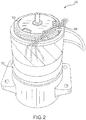
FIG. 2 illustrates a perspective view of an exemplary electromechanical brake actuator having a locking solenoid, in accordance with various embodiments; -
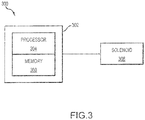
FIG. 3 illustrates a schematic view of a control unit for controlling a solenoid, in accordance with various embodiments; -
FIG. 4 illustrates an exemplary waveform of the current passing through a bistable solenoid during the switching process, in accordance with various embodiments; and -
FIG. 5 illustrates an exemplary process for determining the state of a solenoid, in accordance with various embodiments. - The detailed description of exemplary embodiments herein makes reference to the accompanying drawings, which show exemplary embodiments by way of illustration and their best mode. While these exemplary embodiments are described in sufficient detail to enable those skilled in the art to practice the disclosures, it should be understood that other embodiments may be realized and that logical, chemical, and mechanical changes may be made without departing from the spirit and scope of the disclosures. Thus, the detailed description herein is presented for purposes of illustration only and not of limitation. For example, the steps recited in any of the method or process descriptions may be executed in any order and are not necessarily limited to the order presented. Furthermore, any reference to singular includes plural embodiments, and any reference to more than one component or step may include a singular embodiment or step. Also, any reference to attached, fixed, connected or the like may include permanent, removable, temporary, partial, full and/or any other possible attachment option. Additionally, any reference to without contact (or similar phrases) may also include reduced contact or minimal contact.
- Electromechanical actuators (EMA) may be used to stop and slow aircraft by providing compressive force. When parked, the EMA may be locked into a braking position using a solenoid. The solenoid position may be controlled and/or determined using current. The wave form of current passing though the solenoid in response to the solenoid being energized may be used to determine the solenoid position. With reference to
FIG. 1 , a perspective view of anexemplary brake 100 is shown, in accordance with various embodiments.Brake 100 may comprise abrake stack 102 having a cylindrical geometry. EMAassemblies 104 may be disposed at an end ofbrake 100. Althoughbrake 100 is illustrated having fourEMA assemblies 104, any number ofEMA assemblies 104 may be used to apply pressure tobrake stack 102. EMAassemblies 104 may each be configured to apply compressive force tobrake stack 102 and thereby slow or stop an aircraft.EMA assemblies 104 may include locking mechanisms in the form of solenoids. - With reference to
FIG. 2 , an exemplarylocking EMA assembly 200 is shown, in accordance with various embodiments. LockingEMA assembly 200 may include an EMA 202 configured to apply compressive force to a brake stack. The EMA may actuate towards and away from the brake stack to increase or decrease braking force, respectively. Asolenoid 204 may be mechanically coupled toEMA 202 to provide electronic locking and/or unlocking ofEMA 202 in braking positions.Solenoid 204 may be a bistable device that locksEMA 202 in one state and allowsEMA 104 to spin freely in the second state.Solenoid 204 may move in response to a current provided through one ormore wires 206. Althoughsolenoid 204 is illustrated in a braking application for exemplary purposes, the systems and process disclosed herein may be used in any solenoid application. In that regard,solenoid 204 may be any form of solenoid actuator including a bistable solenoid, linear solenoid, rotary solenoid, voice coil, or other form of solenoid. - With reference to
FIG. 3 , an exemplarysolenoid control system 300 for determining a state of a solenoid is shown, in accordance with various embodiments.Control unit 302 may be integrated into an electronic brake actuator controller (EBAC) or other control unit.Control unit 302 may also be implemented as a discrete controller.Control unit 302 may include one ormore processors 304 and one or more tangible,non-transitory memories 306 and be capable of implementing logic (as discussed below with reference toFIGs. 4 and5 ).Processor 304 can be a general purpose processor, a digital signal processor (DSP), an application specific integrated circuit (ASIC), a field programmable gate array (FPGA) or other programmable logic device, discrete gate or transistor logic, discrete hardware components, or any combination thereof. The processor may thus be configured to implement various logical operations in response to execution of instructions, for example, instructions stored on a non-transitory, tangible, computer-readable medium.Control unit 302 may be in electronic communication withsolenoid 308. In that regard,control unit 302 may measure and analyze the electronicsignal driving solenoid 308. - As used herein, the term "non-transitory" is to be understood to remove only propagating transitory signals per se from the claim scope and does not relinquish rights to all standard computer-readable media that are not only propagating transitory signals per se. Stated another way, the meaning of the term "non-transitory computer-readable medium" and "non-transitory computer-readable storage medium" should be construed to exclude only those types of transitory computer-readable media which were found in In Re Nuijten to fall outside the scope of patentable subject matter under 35 U.S.C. § 101.
- With reference to
FIG. 4 , anexemplary plot 400 of the current 402 passing through a solenoid to effectuate actuation over time, in accordance with various embodiments. The solenoid through which the current is passing may be any solenoid for any application including the exemplary braking application disclosed above.Plot 400 includes points of interest that correspond to the state of current 402 and the state of the solenoid. For example,plot 400 may be used to identify when the solenoid begins moving, and when the solenoid stops moving based on a power drive signal such as current 402. Plot 400 may also include local extrema and the rate of change of current 402 that may be used to identify the state of the solenoid. Plot 400 may be generated by sampling current 402 at intervals and calculating the values. For example, current 402 may be sampled 1,000 times per second (1 kHz) to determine the current at each sample time as well as the change in current over time (i.e., the slope or first derivative of current). - In various embodiments, current begins passing through the solenoid at time T0. The current passing through the solenoid generally increases until time T1. At time T1, a local maximum in current is present. Current C1 passes through the solenoid at time T1. The solenoid begins moving in response to current C1.
- In various embodiments, the solenoid may complete switching at or around time T2. The current C2 passing through the solenoid at time T2 may be a local minimum. Current C2 may also be the next local extrema after C1. In that regard, C2 may be less than C1. The segment of
plot 400 spanning from T1 to T2 may be referred to as S1. - In various embodiments, the current generally decreases over segment S1. Using Cartesian coordinates, the slope (i.e., rate of change or derivative) of
plot 400 at between two points (Tx, Cx) and (Ty, Cy) may be calculated Cy-Cx/Ty-Tx. Thus, the average slope (i.e., the rate of change) of segment S1 may be defined as C2-C1/T2-T1, which may a negative number since C1 is greater than C2. The solenoid may complete its actuation or movement at time T2. The current value may rise after time T2 in response to the solenoid completing its movement or actuation as the coil of the solenoid charges. - In various embodiments, the segment S2 may extend from time T2 to time T3. At time T3, current may have value C3. Segment S2 may generally include increasing current values from C2 to C3. C3 may be greater than C1 and/or C2. The solenoid may be at rest during segment S2.
- With reference to
FIG. 5 , aprocess 500 for determining the state of a solenoid (e.g.,solenoid 308 ofFIG. 3 ) based on the power drive signal (e.g., current 402 ofFIG. 4 ) passing through the solenoid is shown, in accordance with various embodiments.Process 500 may be conducted by a control unit such ascontrol unit 302 ofFIG. 3 .Control unit 302 may control the exciting electrical energy delivered tosolenoid 308. For example,control unit 302 may control the exciting electrical energy's amplitude, on/off time, and/or polarity.Control unit 302 may control the electricity used to excitesolenoid 308 and thereby initiate the movement of solenoid 308 (Block 502). The power drive signal used to determine the state of the solenoid (e.g., a feedback signal from the solenoid) may be an electronic signal such as a voltage signal or a current signal. The characteristics of the signal may be used to determine the state of the solenoid. - In various embodiments,
control unit 302 may measure the current flowing through the solenoid in response to the solenoid being activated (Block 504). For example, a current measurement device may be placed in series with the solenoid to measure current through the solenoid. Similarly, voltage may be used to identify solenoid state by placing a voltage measurement device in parallel with the solenoid to measure the voltage change across the solenoid. - In various embodiments,
control unit 302 may detect characteristics of the current flowing through the solenoid to determine the solenoid state (Block 506). Characteristics of the current may include the characteristics ofplot 400 of current 402 as described above with reference toFIG. 4 . Some of the characteristics ofplot 400 useful to in determining solenoid state may include local extrema and slopes. - In various embodiments,
control unit 302 may identify the time at which solenoid 308 starts moving by detecting point (T1, C1) ofFIG. 4 . Point (T1, C1) may be identified by finding local extrema, identifying discrete current values (such as C1), identifying a time (such as T1), identifying the rate of change of the current (i.e., the first derivative or slope of the current), or identifying other characteristics of the powersignal driving solenoid 308. The current may be sampled to identify characteristics of the current. Sampling may include measuring the current repeatedly at regular and/or irregular intervals. For example,control unit 302 may measure the current at a frequency of 10, kHz, 1 kHz, 500 Hz, or any desired frequency. Finer granularity (i.e., higher sampling frequency) may be used as the complete switching ofsolenoid 308 between states may take less than one second. - In various embodiments, local extrema (minimums and maximums where the slope of
plot 400 differs in sign on either side) may be located by identifying times where the rate of change of the current (i.e., first derivative of current) is substantially equal to zero and/or determining whether the sign (+/-) of the rate of change of the current changes at that time. Due to the nature of sampling, a precise time at which the rate of change equals zero may be difficult to identify. The solenoid may begin switching at approximately the time where a local maximum occurs (i.e., where the sign of the slope of the current changes from + to -), and the solenoid may complete switching at approximately the time where the local minimum occurs (i.e., where the sign of the slope of the current changes from - to +). - In various embodiments, discrete current and/or time values may be used to identify solenoid state. For example,
control unit 302 may detectsolenoid 308 beginning to switch by detecting that the current has risen to approximately C1 for the first time since excitation ofsolenoid 308.Control unit 302 may detectsolenoid 308 completing switching by detecting that the current has dropped to C2 after rising to C1. - In various embodiments,
control unit 302 may identify slopes over a timespan to determine the state ofsolenoid 308. For example,control unit 302 may determine thatsolenoid 308 is in the process of switching by identifying a time period when the slope of the current is approximately equal to the average slope over segment S1 of plot 400 (C2-C1/T2-T1).Control unit 302 may identify the foregoing characteristics, alone or in conjunction, to determine solenoid state. In addition, other characteristics of current 402 drivingsolenoid 308 may be suitable for use in determine the state ofsolenoid 308. Furthermore, the foregoing characteristics of the current signal driving an actuator may be used to identify discrete points of interest with respect to solenoid state. - In various embodiments, the state of a solenoid may thus be determined without additional detection hardware on the solenoid to determine its state. As a result, additional weight may not be added to weight-sensitive installations. Furthermore, the signal may be detected without adding pins or interconnecting wires. Identifying the state of
solenoid 308 tends to increase the safety of asystem using solenoid 308 by enabling detection that solenoid 308 completed a state change and is in the desired position based on the characteristics of the current. For example, identifying a solenoid state may signify that a parking brake on an aircraft has successfully engaged and/or disengaged. - Benefits, other advantages, and solutions to problems have been described herein with regard to specific embodiments. Furthermore, the connecting lines shown in the various figures contained herein are intended to represent exemplary functional relationships and/or physical couplings between the various elements. It should be noted that many alternative or additional functional relationships or physical connections may be present in a practical system. However, the benefits, advantages, solutions to problems, and any elements that may cause any benefit, advantage, or solution to occur or become more pronounced are not to be construed as critical, required, or essential features or elements of the disclosures. The scope of the disclosures is accordingly to be limited by nothing other than the appended claims, in which reference to an element in the singular is not intended to mean "one and only one" unless explicitly so stated, but rather "one or more." Moreover, where a phrase similar to "at least one of A, B, or C" is used in the claims, it is intended that the phrase be interpreted to mean that A alone may be present in an embodiment, B alone may be present in an embodiment, C alone may be present in an embodiment, or that any combination of the elements A, B and C may be present in a single embodiment; for example, A and B, A and C, B and C, or A and B and C. Different cross-hatching is used throughout the figures to denote different parts but not necessarily to denote the same or different materials.
- Systems, methods and apparatus are provided herein. In the detailed description herein, references to "one embodiment", "an embodiment", "an example embodiment", etc., indicate that the embodiment described may include a particular feature, structure, or characteristic, but every embodiment may not necessarily include the particular feature, structure, or characteristic. Moreover, such phrases are not necessarily referring to the same embodiment. Further, when a particular feature, structure, or characteristic is described in connection with an embodiment, it is submitted that it is within the knowledge of one skilled in the art to affect such feature, structure, or characteristic in connection with other embodiments whether or not explicitly described. After reading the description, it will be apparent to one skilled in the relevant art(s) how to implement the disclosure in alternative embodiments.
- Furthermore, no element, component, or method step in the present disclosure is intended to be dedicated to the public regardless of whether the element, component, or method step is explicitly recited in the claims. No claim element herein is to be construed under the provisions of 35 U.S.C. 112(f), unless the element is expressly recited using the phrase "means for." As used herein, the terms "comprises", "comprising", or any other variation thereof, are intended to cover a non-exclusive inclusion, such that a process, method, article, or apparatus that comprises a list of elements does not include only those elements but may include other elements not expressly listed or inherent to such process, method, article, or apparatus.
Claims (15)
- A brake control system (300), comprising:a control unit (302); anda solenoid (204, 308) electronically coupled to the control unit (302),wherein the control unit (302) is configured to monitor (504) a current passing through the solenoid,wherein the control unit is configured to detect (506) characteristics of the current flowing through the solenoid to determine a state of the solenoid.
- The brake control system of claim 1, wherein the solenoid (204, 308) is configured to move in response to the control unit (302) turning on an electric signal.
- The brake control system of claim 2, wherein the state of the solenoid (204, 308) indicates that the solenoid (204, 308) has changed position.
- The brake control system of claim 2, wherein the solenoid (204, 308) comprises a bistable device.
- The brake control system of claim 4, wherein the control unit (302) comprises a memory and a processor.
- The brake control system of claim 4, further comprising an electromechanical actuator (EMA) mechanically coupled to the solenoid, wherein the solenoid is configured to lock the EMA, and preferably further comprising a brake stack, wherein the solenoid is configured to lock the EMA with the EMA applying a force to the brake stack.
- A method for controlling a solenoid (204, 308), comprising:measuring (504) a current flowing through the solenoid (204, 308); anddetecting (506) characteristics of the current flowing through the solenoid (204, 308) to determine a state of the solenoid (204, 308).
- The method of claim 7, further comprising applying an electric signal to the solenoid (204, 308) to activate the solenoid (204, 308).
- The method of claim 8, further comprising ending the electric signal to the solenoid (204, 308) in response to the characteristics of the current flowing through the solenoid (204, 308) indicating the state of the solenoid (204, 308).
- The method of claim 8, wherein the state of the solenoid (204, 308) indicates that the solenoid (204, 308) has changed position, and/or wherein the characteristics of the current comprise at least one of a local extrema of the current, a rate of change of the current, or a discrete value of the current, and/or further comprising identifying a first derivative of the current to detect the solenoid (204, 308) is moving.
- The method of any of claims 7 to 10, wherein the solenoid (204, 308) comprises a bistable device.
- An article of manufacture including a non-transitory, tangible computer readable storage medium having instructions stored thereon that, in response to execution by a processor, cause a brake system to perform operations comprising:measuring (504) a current flowing through a solenoid; anddetecting (506) characteristics of the current flowing through the solenoid (204, 308) to determine a state of the solenoid (204, 308).
- The article of claim 12, further comprising applying an electric signal to the solenoid to activate the solenoid (204, 308).
- The article of claim 13, wherein the state of the solenoid (204, 308) indicates that the solenoid (204, 308) has changed position, or wherein the state of the solenoid (204, 308) is changing positions.
- The article of any of claims 12 to 14, wherein the characteristics of the current comprise at least one of a local extrema of the current, a rate of change of the current, or a discrete value of the current, and/or wherein the solenoid (204, 308) comprises a bistable device.
Applications Claiming Priority (1)
| Application Number | Priority Date | Filing Date | Title |
|---|---|---|---|
| US15/006,351 US9640311B1 (en) | 2016-01-26 | 2016-01-26 | Systems and methods for solenoid state determination |
Publications (2)
| Publication Number | Publication Date |
|---|---|
| EP3199415A1 true EP3199415A1 (en) | 2017-08-02 |
| EP3199415B1 EP3199415B1 (en) | 2022-04-20 |
Family
ID=57914731
Family Applications (1)
| Application Number | Title | Priority Date | Filing Date |
|---|---|---|---|
| EP17152780.7A Active EP3199415B1 (en) | 2016-01-26 | 2017-01-24 | Systems and methods for solenoid state determination |
Country Status (2)
| Country | Link |
|---|---|
| US (1) | US9640311B1 (en) |
| EP (1) | EP3199415B1 (en) |
Families Citing this family (3)
| Publication number | Priority date | Publication date | Assignee | Title |
|---|---|---|---|---|
| US11007991B2 (en) * | 2017-09-11 | 2021-05-18 | Robert Bosch Gmbh | Device for controlling a solenoid valve |
| FR3096635B1 (en) * | 2019-06-03 | 2021-06-18 | Safran Landing Systems | Detection of the state of a parking brake unit |
| DE102021205142A1 (en) * | 2021-05-20 | 2022-11-24 | Festo Se & Co. Kg | Solenoid valve system and method of operating a solenoid valve system |
Citations (3)
| Publication number | Priority date | Publication date | Assignee | Title |
|---|---|---|---|---|
| US20100051395A1 (en) * | 2008-08-29 | 2010-03-04 | Kazumoto Sano | Electric disk brake |
| JP2011131706A (en) * | 2009-12-24 | 2011-07-07 | Toyota Motor Corp | Brake control device and operation determining method of solenoid valve |
| EP2930504A2 (en) * | 2014-04-09 | 2015-10-14 | Goodrich Corporation | State sensor system and methods |
Family Cites Families (9)
| Publication number | Priority date | Publication date | Assignee | Title |
|---|---|---|---|---|
| WO2000044007A1 (en) | 1999-01-20 | 2000-07-27 | Unisia Jecs Corporation | Solenoid valve control apparatus and brake control apparatus |
| US6300733B1 (en) | 2000-02-22 | 2001-10-09 | Gary E. Bergstrom | System to determine solenoid position and flux without drift |
| US6753493B2 (en) * | 2001-06-01 | 2004-06-22 | Hubbell Incorporated | Electrical circuit interrupting device |
| WO2004076254A1 (en) * | 2003-02-24 | 2004-09-10 | Bendix Commercial Vehicle Systems Llc | Electro-pneumatic latching valve system |
| DE102007032178B3 (en) * | 2007-07-10 | 2008-12-11 | Continental Automotive Gmbh | Motor vehicle control device and associated method for controlling the electrical current of an actuator |
| JP4640386B2 (en) * | 2007-07-20 | 2011-03-02 | トヨタ自動車株式会社 | Brake device and brake control method |
| WO2011055419A1 (en) * | 2009-11-09 | 2011-05-12 | トヨタ自動車株式会社 | Brake controller |
| US9352730B2 (en) * | 2012-10-05 | 2016-05-31 | Toyota Jidosha Kabushiki Kaisha | Vehicle brake control device |
| JP5924416B2 (en) * | 2012-11-16 | 2016-05-25 | トヨタ自動車株式会社 | Brake control device for vehicle |
-
2016
- 2016-01-26 US US15/006,351 patent/US9640311B1/en active Active
-
2017
- 2017-01-24 EP EP17152780.7A patent/EP3199415B1/en active Active
Patent Citations (3)
| Publication number | Priority date | Publication date | Assignee | Title |
|---|---|---|---|---|
| US20100051395A1 (en) * | 2008-08-29 | 2010-03-04 | Kazumoto Sano | Electric disk brake |
| JP2011131706A (en) * | 2009-12-24 | 2011-07-07 | Toyota Motor Corp | Brake control device and operation determining method of solenoid valve |
| EP2930504A2 (en) * | 2014-04-09 | 2015-10-14 | Goodrich Corporation | State sensor system and methods |
Also Published As
| Publication number | Publication date |
|---|---|
| EP3199415B1 (en) | 2022-04-20 |
| US9640311B1 (en) | 2017-05-02 |
Similar Documents
| Publication | Publication Date | Title |
|---|---|---|
| US9640311B1 (en) | Systems and methods for solenoid state determination | |
| CN101873951B (en) | Method to detect shorted solenoid coils | |
| US9800191B2 (en) | Adaptive linear resonance actuator controller | |
| US10131421B2 (en) | Locked wheel extension protection in brake control systems | |
| CN102066172B (en) | Method for the operative monitoring of track brakes | |
| US9366549B2 (en) | State sensor systems and methods | |
| US9851408B2 (en) | Methods and apparatus for battery testing | |
| EP3878703B1 (en) | Systems and methods for brake health monitoring | |
| WO2018092322A1 (en) | Diagnosis device for electromagnetic brake | |
| CN104828058B (en) | Method for checking an automatic parking brake system | |
| EP2949524B1 (en) | Aircraft brake system testing methods | |
| CN107110937B (en) | Method and apparatus for active load impedance monitoring | |
| US11965932B2 (en) | Method for predicting the failure of elementary relays | |
| CN107430169B (en) | Method for determining the operating state of an electromagnetic type MV switchgear | |
| CN112027108B (en) | Detecting a condition of a parking brake member | |
| JP3705828B2 (en) | Power circuit error check method | |
| US8643318B2 (en) | High-resolution and low-resolution sensors for phase detection | |
| CN1800862A (en) | Non-contact measuring system for direct current | |
| KR100807943B1 (en) | Pole motion detection device and pore position estimation device of elevator brake | |
| EP3816080B1 (en) | Brake device for elevator system and testing method for brake device | |
| JP2023091933A (en) | Non-excitation actuated brake, control method for non-excitation actuated brake, and machine tool | |
| CN120675445A (en) | Method for monitoring the state of an electromagnetic locking device of a spinning station of a rotor spinning machine | |
| US20190352174A1 (en) | Position sensing circuit for an electronically driven mems device | |
| DE102020212486A1 (en) | Method and device for monitoring an electric drive | |
| EP3168626A1 (en) | Low wheel speed detection utilizing variable reluctance speed transducer |
Legal Events
| Date | Code | Title | Description |
|---|---|---|---|
| PUAI | Public reference made under article 153(3) epc to a published international application that has entered the european phase |
Free format text: ORIGINAL CODE: 0009012 |
|
| STAA | Information on the status of an ep patent application or granted ep patent |
Free format text: STATUS: THE APPLICATION HAS BEEN PUBLISHED |
|
| AK | Designated contracting states |
Kind code of ref document: A1 Designated state(s): AL AT BE BG CH CY CZ DE DK EE ES FI FR GB GR HR HU IE IS IT LI LT LU LV MC MK MT NL NO PL PT RO RS SE SI SK SM TR |
|
| AX | Request for extension of the european patent |
Extension state: BA ME |
|
| STAA | Information on the status of an ep patent application or granted ep patent |
Free format text: STATUS: REQUEST FOR EXAMINATION WAS MADE |
|
| 17P | Request for examination filed |
Effective date: 20180131 |
|
| RBV | Designated contracting states (corrected) |
Designated state(s): AL AT BE BG CH CY CZ DE DK EE ES FI FR GB GR HR HU IE IS IT LI LT LU LV MC MK MT NL NO PL PT RO RS SE SI SK SM TR |
|
| STAA | Information on the status of an ep patent application or granted ep patent |
Free format text: STATUS: EXAMINATION IS IN PROGRESS |
|
| 17Q | First examination report despatched |
Effective date: 20200508 |
|
| GRAP | Despatch of communication of intention to grant a patent |
Free format text: ORIGINAL CODE: EPIDOSNIGR1 |
|
| STAA | Information on the status of an ep patent application or granted ep patent |
Free format text: STATUS: GRANT OF PATENT IS INTENDED |
|
| INTG | Intention to grant announced |
Effective date: 20211118 |
|
| GRAS | Grant fee paid |
Free format text: ORIGINAL CODE: EPIDOSNIGR3 |
|
| GRAA | (expected) grant |
Free format text: ORIGINAL CODE: 0009210 |
|
| STAA | Information on the status of an ep patent application or granted ep patent |
Free format text: STATUS: THE PATENT HAS BEEN GRANTED |
|
| AK | Designated contracting states |
Kind code of ref document: B1 Designated state(s): AL AT BE BG CH CY CZ DE DK EE ES FI FR GB GR HR HU IE IS IT LI LT LU LV MC MK MT NL NO PL PT RO RS SE SI SK SM TR |
|
| REG | Reference to a national code |
Ref country code: GB Ref legal event code: FG4D |
|
| REG | Reference to a national code |
Ref country code: CH Ref legal event code: EP |
|
| REG | Reference to a national code |
Ref country code: DE Ref legal event code: R096 Ref document number: 602017056133 Country of ref document: DE |
|
| REG | Reference to a national code |
Ref country code: IE Ref legal event code: FG4D |
|
| REG | Reference to a national code |
Ref country code: AT Ref legal event code: REF Ref document number: 1484945 Country of ref document: AT Kind code of ref document: T Effective date: 20220515 |
|
| REG | Reference to a national code |
Ref country code: LT Ref legal event code: MG9D |
|
| REG | Reference to a national code |
Ref country code: NL Ref legal event code: MP Effective date: 20220420 |
|
| REG | Reference to a national code |
Ref country code: AT Ref legal event code: MK05 Ref document number: 1484945 Country of ref document: AT Kind code of ref document: T Effective date: 20220420 |
|
| PG25 | Lapsed in a contracting state [announced via postgrant information from national office to epo] |
Ref country code: NL Free format text: LAPSE BECAUSE OF FAILURE TO SUBMIT A TRANSLATION OF THE DESCRIPTION OR TO PAY THE FEE WITHIN THE PRESCRIBED TIME-LIMIT Effective date: 20220420 |
|
| PG25 | Lapsed in a contracting state [announced via postgrant information from national office to epo] |
Ref country code: SE Free format text: LAPSE BECAUSE OF FAILURE TO SUBMIT A TRANSLATION OF THE DESCRIPTION OR TO PAY THE FEE WITHIN THE PRESCRIBED TIME-LIMIT Effective date: 20220420 Ref country code: PT Free format text: LAPSE BECAUSE OF FAILURE TO SUBMIT A TRANSLATION OF THE DESCRIPTION OR TO PAY THE FEE WITHIN THE PRESCRIBED TIME-LIMIT Effective date: 20220822 Ref country code: NO Free format text: LAPSE BECAUSE OF FAILURE TO SUBMIT A TRANSLATION OF THE DESCRIPTION OR TO PAY THE FEE WITHIN THE PRESCRIBED TIME-LIMIT Effective date: 20220720 Ref country code: LT Free format text: LAPSE BECAUSE OF FAILURE TO SUBMIT A TRANSLATION OF THE DESCRIPTION OR TO PAY THE FEE WITHIN THE PRESCRIBED TIME-LIMIT Effective date: 20220420 Ref country code: HR Free format text: LAPSE BECAUSE OF FAILURE TO SUBMIT A TRANSLATION OF THE DESCRIPTION OR TO PAY THE FEE WITHIN THE PRESCRIBED TIME-LIMIT Effective date: 20220420 Ref country code: GR Free format text: LAPSE BECAUSE OF FAILURE TO SUBMIT A TRANSLATION OF THE DESCRIPTION OR TO PAY THE FEE WITHIN THE PRESCRIBED TIME-LIMIT Effective date: 20220721 Ref country code: FI Free format text: LAPSE BECAUSE OF FAILURE TO SUBMIT A TRANSLATION OF THE DESCRIPTION OR TO PAY THE FEE WITHIN THE PRESCRIBED TIME-LIMIT Effective date: 20220420 Ref country code: ES Free format text: LAPSE BECAUSE OF FAILURE TO SUBMIT A TRANSLATION OF THE DESCRIPTION OR TO PAY THE FEE WITHIN THE PRESCRIBED TIME-LIMIT Effective date: 20220420 Ref country code: BG Free format text: LAPSE BECAUSE OF FAILURE TO SUBMIT A TRANSLATION OF THE DESCRIPTION OR TO PAY THE FEE WITHIN THE PRESCRIBED TIME-LIMIT Effective date: 20220720 Ref country code: AT Free format text: LAPSE BECAUSE OF FAILURE TO SUBMIT A TRANSLATION OF THE DESCRIPTION OR TO PAY THE FEE WITHIN THE PRESCRIBED TIME-LIMIT Effective date: 20220420 |
|
| PG25 | Lapsed in a contracting state [announced via postgrant information from national office to epo] |
Ref country code: RS Free format text: LAPSE BECAUSE OF FAILURE TO SUBMIT A TRANSLATION OF THE DESCRIPTION OR TO PAY THE FEE WITHIN THE PRESCRIBED TIME-LIMIT Effective date: 20220420 Ref country code: PL Free format text: LAPSE BECAUSE OF FAILURE TO SUBMIT A TRANSLATION OF THE DESCRIPTION OR TO PAY THE FEE WITHIN THE PRESCRIBED TIME-LIMIT Effective date: 20220420 Ref country code: LV Free format text: LAPSE BECAUSE OF FAILURE TO SUBMIT A TRANSLATION OF THE DESCRIPTION OR TO PAY THE FEE WITHIN THE PRESCRIBED TIME-LIMIT Effective date: 20220420 Ref country code: IS Free format text: LAPSE BECAUSE OF FAILURE TO SUBMIT A TRANSLATION OF THE DESCRIPTION OR TO PAY THE FEE WITHIN THE PRESCRIBED TIME-LIMIT Effective date: 20220820 |
|
| REG | Reference to a national code |
Ref country code: DE Ref legal event code: R097 Ref document number: 602017056133 Country of ref document: DE |
|
| PG25 | Lapsed in a contracting state [announced via postgrant information from national office to epo] |
Ref country code: SM Free format text: LAPSE BECAUSE OF FAILURE TO SUBMIT A TRANSLATION OF THE DESCRIPTION OR TO PAY THE FEE WITHIN THE PRESCRIBED TIME-LIMIT Effective date: 20220420 Ref country code: SK Free format text: LAPSE BECAUSE OF FAILURE TO SUBMIT A TRANSLATION OF THE DESCRIPTION OR TO PAY THE FEE WITHIN THE PRESCRIBED TIME-LIMIT Effective date: 20220420 Ref country code: RO Free format text: LAPSE BECAUSE OF FAILURE TO SUBMIT A TRANSLATION OF THE DESCRIPTION OR TO PAY THE FEE WITHIN THE PRESCRIBED TIME-LIMIT Effective date: 20220420 Ref country code: EE Free format text: LAPSE BECAUSE OF FAILURE TO SUBMIT A TRANSLATION OF THE DESCRIPTION OR TO PAY THE FEE WITHIN THE PRESCRIBED TIME-LIMIT Effective date: 20220420 Ref country code: DK Free format text: LAPSE BECAUSE OF FAILURE TO SUBMIT A TRANSLATION OF THE DESCRIPTION OR TO PAY THE FEE WITHIN THE PRESCRIBED TIME-LIMIT Effective date: 20220420 Ref country code: CZ Free format text: LAPSE BECAUSE OF FAILURE TO SUBMIT A TRANSLATION OF THE DESCRIPTION OR TO PAY THE FEE WITHIN THE PRESCRIBED TIME-LIMIT Effective date: 20220420 |
|
| PLBE | No opposition filed within time limit |
Free format text: ORIGINAL CODE: 0009261 |
|
| STAA | Information on the status of an ep patent application or granted ep patent |
Free format text: STATUS: NO OPPOSITION FILED WITHIN TIME LIMIT |
|
| 26N | No opposition filed |
Effective date: 20230123 |
|
| PG25 | Lapsed in a contracting state [announced via postgrant information from national office to epo] |
Ref country code: AL Free format text: LAPSE BECAUSE OF FAILURE TO SUBMIT A TRANSLATION OF THE DESCRIPTION OR TO PAY THE FEE WITHIN THE PRESCRIBED TIME-LIMIT Effective date: 20220420 |
|
| PG25 | Lapsed in a contracting state [announced via postgrant information from national office to epo] |
Ref country code: SI Free format text: LAPSE BECAUSE OF FAILURE TO SUBMIT A TRANSLATION OF THE DESCRIPTION OR TO PAY THE FEE WITHIN THE PRESCRIBED TIME-LIMIT Effective date: 20220420 |
|
| P01 | Opt-out of the competence of the unified patent court (upc) registered |
Effective date: 20230522 |
|
| REG | Reference to a national code |
Ref country code: DE Ref legal event code: R119 Ref document number: 602017056133 Country of ref document: DE |
|
| REG | Reference to a national code |
Ref country code: CH Ref legal event code: PL |
|
| PG25 | Lapsed in a contracting state [announced via postgrant information from national office to epo] |
Ref country code: LU Free format text: LAPSE BECAUSE OF NON-PAYMENT OF DUE FEES Effective date: 20230124 |
|
| REG | Reference to a national code |
Ref country code: BE Ref legal event code: MM Effective date: 20230131 |
|
| PG25 | Lapsed in a contracting state [announced via postgrant information from national office to epo] |
Ref country code: LI Free format text: LAPSE BECAUSE OF NON-PAYMENT OF DUE FEES Effective date: 20230131 Ref country code: DE Free format text: LAPSE BECAUSE OF NON-PAYMENT OF DUE FEES Effective date: 20230801 Ref country code: CH Free format text: LAPSE BECAUSE OF NON-PAYMENT OF DUE FEES Effective date: 20230131 |
|
| PG25 | Lapsed in a contracting state [announced via postgrant information from national office to epo] |
Ref country code: BE Free format text: LAPSE BECAUSE OF NON-PAYMENT OF DUE FEES Effective date: 20230131 |
|
| PG25 | Lapsed in a contracting state [announced via postgrant information from national office to epo] |
Ref country code: IT Free format text: LAPSE BECAUSE OF FAILURE TO SUBMIT A TRANSLATION OF THE DESCRIPTION OR TO PAY THE FEE WITHIN THE PRESCRIBED TIME-LIMIT Effective date: 20220420 Ref country code: IE Free format text: LAPSE BECAUSE OF NON-PAYMENT OF DUE FEES Effective date: 20230124 |
|
| PG25 | Lapsed in a contracting state [announced via postgrant information from national office to epo] |
Ref country code: MC Free format text: LAPSE BECAUSE OF FAILURE TO SUBMIT A TRANSLATION OF THE DESCRIPTION OR TO PAY THE FEE WITHIN THE PRESCRIBED TIME-LIMIT Effective date: 20220420 |
|
| PG25 | Lapsed in a contracting state [announced via postgrant information from national office to epo] |
Ref country code: MC Free format text: LAPSE BECAUSE OF FAILURE TO SUBMIT A TRANSLATION OF THE DESCRIPTION OR TO PAY THE FEE WITHIN THE PRESCRIBED TIME-LIMIT Effective date: 20220420 |
|
| PG25 | Lapsed in a contracting state [announced via postgrant information from national office to epo] |
Ref country code: BG Free format text: LAPSE BECAUSE OF FAILURE TO SUBMIT A TRANSLATION OF THE DESCRIPTION OR TO PAY THE FEE WITHIN THE PRESCRIBED TIME-LIMIT Effective date: 20220420 |
|
| PG25 | Lapsed in a contracting state [announced via postgrant information from national office to epo] |
Ref country code: BG Free format text: LAPSE BECAUSE OF FAILURE TO SUBMIT A TRANSLATION OF THE DESCRIPTION OR TO PAY THE FEE WITHIN THE PRESCRIBED TIME-LIMIT Effective date: 20220420 |
|
| PG25 | Lapsed in a contracting state [announced via postgrant information from national office to epo] |
Ref country code: CY Free format text: LAPSE BECAUSE OF FAILURE TO SUBMIT A TRANSLATION OF THE DESCRIPTION OR TO PAY THE FEE WITHIN THE PRESCRIBED TIME-LIMIT; INVALID AB INITIO Effective date: 20170124 |
|
| PG25 | Lapsed in a contracting state [announced via postgrant information from national office to epo] |
Ref country code: HU Free format text: LAPSE BECAUSE OF FAILURE TO SUBMIT A TRANSLATION OF THE DESCRIPTION OR TO PAY THE FEE WITHIN THE PRESCRIBED TIME-LIMIT; INVALID AB INITIO Effective date: 20170124 |
|
| PG25 | Lapsed in a contracting state [announced via postgrant information from national office to epo] |
Ref country code: TR Free format text: LAPSE BECAUSE OF FAILURE TO SUBMIT A TRANSLATION OF THE DESCRIPTION OR TO PAY THE FEE WITHIN THE PRESCRIBED TIME-LIMIT Effective date: 20220420 |
|
| PGFP | Annual fee paid to national office [announced via postgrant information from national office to epo] |
Ref country code: GB Payment date: 20251220 Year of fee payment: 10 |
|
| PGFP | Annual fee paid to national office [announced via postgrant information from national office to epo] |
Ref country code: FR Payment date: 20251217 Year of fee payment: 10 |