EP3199222A1 - Heater arrangement for tepsa system - Google Patents
Heater arrangement for tepsa system Download PDFInfo
- Publication number
- EP3199222A1 EP3199222A1 EP17153518.0A EP17153518A EP3199222A1 EP 3199222 A1 EP3199222 A1 EP 3199222A1 EP 17153518 A EP17153518 A EP 17153518A EP 3199222 A1 EP3199222 A1 EP 3199222A1
- Authority
- EP
- European Patent Office
- Prior art keywords
- regeneration
- heater
- regeneration gas
- gas
- temperature
- Prior art date
- Legal status (The legal status is an assumption and is not a legal conclusion. Google has not performed a legal analysis and makes no representation as to the accuracy of the status listed.)
- Granted
Links
- 230000008929 regeneration Effects 0.000 claims abstract description 218
- 238000011069 regeneration method Methods 0.000 claims abstract description 218
- 238000000034 method Methods 0.000 claims abstract description 79
- 238000001179 sorption measurement Methods 0.000 claims abstract description 33
- 239000000203 mixture Substances 0.000 claims abstract description 26
- 239000003463 adsorbent Substances 0.000 claims description 78
- 230000001172 regenerating effect Effects 0.000 claims description 18
- 238000010438 heat treatment Methods 0.000 claims description 17
- 239000006096 absorbing agent Substances 0.000 claims description 3
- 239000007789 gas Substances 0.000 description 137
- 238000009413 insulation Methods 0.000 description 26
- 238000001816 cooling Methods 0.000 description 12
- CURLTUGMZLYLDI-UHFFFAOYSA-N Carbon dioxide Chemical compound O=C=O CURLTUGMZLYLDI-UHFFFAOYSA-N 0.000 description 10
- 238000011144 upstream manufacturing Methods 0.000 description 10
- 238000010926 purge Methods 0.000 description 9
- 238000010586 diagram Methods 0.000 description 8
- 229910002092 carbon dioxide Inorganic materials 0.000 description 7
- 238000012423 maintenance Methods 0.000 description 7
- 230000000052 comparative effect Effects 0.000 description 6
- 230000000694 effects Effects 0.000 description 5
- XLYOFNOQVPJJNP-UHFFFAOYSA-N water Substances O XLYOFNOQVPJJNP-UHFFFAOYSA-N 0.000 description 5
- IJGRMHOSHXDMSA-UHFFFAOYSA-N Atomic nitrogen Chemical compound N#N IJGRMHOSHXDMSA-UHFFFAOYSA-N 0.000 description 4
- 239000001569 carbon dioxide Substances 0.000 description 4
- 238000002474 experimental method Methods 0.000 description 4
- 238000005259 measurement Methods 0.000 description 4
- 238000000926 separation method Methods 0.000 description 4
- 238000012360 testing method Methods 0.000 description 4
- 230000007423 decrease Effects 0.000 description 3
- 230000006866 deterioration Effects 0.000 description 3
- 238000000746 purification Methods 0.000 description 3
- 239000007787 solid Substances 0.000 description 3
- XKRFYHLGVUSROY-UHFFFAOYSA-N Argon Chemical compound [Ar] XKRFYHLGVUSROY-UHFFFAOYSA-N 0.000 description 2
- 230000015556 catabolic process Effects 0.000 description 2
- 238000006731 degradation reaction Methods 0.000 description 2
- 238000003795 desorption Methods 0.000 description 2
- 230000004907 flux Effects 0.000 description 2
- 229910052757 nitrogen Inorganic materials 0.000 description 2
- 238000013022 venting Methods 0.000 description 2
- 230000002411 adverse Effects 0.000 description 1
- 229910052786 argon Inorganic materials 0.000 description 1
- QVGXLLKOCUKJST-UHFFFAOYSA-N atomic oxygen Chemical compound [O] QVGXLLKOCUKJST-UHFFFAOYSA-N 0.000 description 1
- 238000004364 calculation method Methods 0.000 description 1
- 229910052799 carbon Inorganic materials 0.000 description 1
- 230000003247 decreasing effect Effects 0.000 description 1
- 230000000593 degrading effect Effects 0.000 description 1
- 230000001419 dependent effect Effects 0.000 description 1
- 238000004821 distillation Methods 0.000 description 1
- 239000000835 fiber Substances 0.000 description 1
- 239000012774 insulation material Substances 0.000 description 1
- 239000000463 material Substances 0.000 description 1
- 230000003278 mimic effect Effects 0.000 description 1
- 239000001301 oxygen Substances 0.000 description 1
- 229910052760 oxygen Inorganic materials 0.000 description 1
- 230000000737 periodic effect Effects 0.000 description 1
- 230000000717 retained effect Effects 0.000 description 1
- 230000003584 silencer Effects 0.000 description 1
- 238000004088 simulation Methods 0.000 description 1
Images


Classifications
-
- B—PERFORMING OPERATIONS; TRANSPORTING
- B01—PHYSICAL OR CHEMICAL PROCESSES OR APPARATUS IN GENERAL
- B01D—SEPARATION
- B01D53/00—Separation of gases or vapours; Recovering vapours of volatile solvents from gases; Chemical or biological purification of waste gases, e.g. engine exhaust gases, smoke, fumes, flue gases, aerosols
- B01D53/02—Separation of gases or vapours; Recovering vapours of volatile solvents from gases; Chemical or biological purification of waste gases, e.g. engine exhaust gases, smoke, fumes, flue gases, aerosols by adsorption, e.g. preparative gas chromatography
- B01D53/04—Separation of gases or vapours; Recovering vapours of volatile solvents from gases; Chemical or biological purification of waste gases, e.g. engine exhaust gases, smoke, fumes, flue gases, aerosols by adsorption, e.g. preparative gas chromatography with stationary adsorbents
- B01D53/0407—Constructional details of adsorbing systems
- B01D53/0438—Cooling or heating systems
-
- B—PERFORMING OPERATIONS; TRANSPORTING
- B01—PHYSICAL OR CHEMICAL PROCESSES OR APPARATUS IN GENERAL
- B01D—SEPARATION
- B01D53/00—Separation of gases or vapours; Recovering vapours of volatile solvents from gases; Chemical or biological purification of waste gases, e.g. engine exhaust gases, smoke, fumes, flue gases, aerosols
- B01D53/02—Separation of gases or vapours; Recovering vapours of volatile solvents from gases; Chemical or biological purification of waste gases, e.g. engine exhaust gases, smoke, fumes, flue gases, aerosols by adsorption, e.g. preparative gas chromatography
- B01D53/04—Separation of gases or vapours; Recovering vapours of volatile solvents from gases; Chemical or biological purification of waste gases, e.g. engine exhaust gases, smoke, fumes, flue gases, aerosols by adsorption, e.g. preparative gas chromatography with stationary adsorbents
- B01D53/047—Pressure swing adsorption
-
- B—PERFORMING OPERATIONS; TRANSPORTING
- B01—PHYSICAL OR CHEMICAL PROCESSES OR APPARATUS IN GENERAL
- B01D—SEPARATION
- B01D53/00—Separation of gases or vapours; Recovering vapours of volatile solvents from gases; Chemical or biological purification of waste gases, e.g. engine exhaust gases, smoke, fumes, flue gases, aerosols
- B01D53/02—Separation of gases or vapours; Recovering vapours of volatile solvents from gases; Chemical or biological purification of waste gases, e.g. engine exhaust gases, smoke, fumes, flue gases, aerosols by adsorption, e.g. preparative gas chromatography
- B01D53/04—Separation of gases or vapours; Recovering vapours of volatile solvents from gases; Chemical or biological purification of waste gases, e.g. engine exhaust gases, smoke, fumes, flue gases, aerosols by adsorption, e.g. preparative gas chromatography with stationary adsorbents
- B01D53/0407—Constructional details of adsorbing systems
- B01D53/0423—Beds in columns
-
- B—PERFORMING OPERATIONS; TRANSPORTING
- B01—PHYSICAL OR CHEMICAL PROCESSES OR APPARATUS IN GENERAL
- B01D—SEPARATION
- B01D53/00—Separation of gases or vapours; Recovering vapours of volatile solvents from gases; Chemical or biological purification of waste gases, e.g. engine exhaust gases, smoke, fumes, flue gases, aerosols
- B01D53/02—Separation of gases or vapours; Recovering vapours of volatile solvents from gases; Chemical or biological purification of waste gases, e.g. engine exhaust gases, smoke, fumes, flue gases, aerosols by adsorption, e.g. preparative gas chromatography
- B01D53/04—Separation of gases or vapours; Recovering vapours of volatile solvents from gases; Chemical or biological purification of waste gases, e.g. engine exhaust gases, smoke, fumes, flue gases, aerosols by adsorption, e.g. preparative gas chromatography with stationary adsorbents
- B01D53/0462—Temperature swing adsorption
-
- B—PERFORMING OPERATIONS; TRANSPORTING
- B01—PHYSICAL OR CHEMICAL PROCESSES OR APPARATUS IN GENERAL
- B01D—SEPARATION
- B01D53/00—Separation of gases or vapours; Recovering vapours of volatile solvents from gases; Chemical or biological purification of waste gases, e.g. engine exhaust gases, smoke, fumes, flue gases, aerosols
- B01D53/02—Separation of gases or vapours; Recovering vapours of volatile solvents from gases; Chemical or biological purification of waste gases, e.g. engine exhaust gases, smoke, fumes, flue gases, aerosols by adsorption, e.g. preparative gas chromatography
- B01D53/04—Separation of gases or vapours; Recovering vapours of volatile solvents from gases; Chemical or biological purification of waste gases, e.g. engine exhaust gases, smoke, fumes, flue gases, aerosols by adsorption, e.g. preparative gas chromatography with stationary adsorbents
- B01D53/047—Pressure swing adsorption
- B01D53/053—Pressure swing adsorption with storage or buffer vessel
-
- F—MECHANICAL ENGINEERING; LIGHTING; HEATING; WEAPONS; BLASTING
- F25—REFRIGERATION OR COOLING; COMBINED HEATING AND REFRIGERATION SYSTEMS; HEAT PUMP SYSTEMS; MANUFACTURE OR STORAGE OF ICE; LIQUEFACTION SOLIDIFICATION OF GASES
- F25J—LIQUEFACTION, SOLIDIFICATION OR SEPARATION OF GASES OR GASEOUS OR LIQUEFIED GASEOUS MIXTURES BY PRESSURE AND COLD TREATMENT OR BY BRINGING THEM INTO THE SUPERCRITICAL STATE
- F25J3/00—Processes or apparatus for separating the constituents of gaseous or liquefied gaseous mixtures involving the use of liquefaction or solidification
- F25J3/02—Processes or apparatus for separating the constituents of gaseous or liquefied gaseous mixtures involving the use of liquefaction or solidification by rectification, i.e. by continuous interchange of heat and material between a vapour stream and a liquid stream
- F25J3/04—Processes or apparatus for separating the constituents of gaseous or liquefied gaseous mixtures involving the use of liquefaction or solidification by rectification, i.e. by continuous interchange of heat and material between a vapour stream and a liquid stream for air
- F25J3/04151—Purification and (pre-)cooling of the feed air; recuperative heat-exchange with product streams
- F25J3/04163—Hot end purification of the feed air
- F25J3/04169—Hot end purification of the feed air by adsorption of the impurities
- F25J3/04181—Regenerating the adsorbents
-
- B—PERFORMING OPERATIONS; TRANSPORTING
- B01—PHYSICAL OR CHEMICAL PROCESSES OR APPARATUS IN GENERAL
- B01D—SEPARATION
- B01D2257/00—Components to be removed
- B01D2257/40—Nitrogen compounds
- B01D2257/402—Dinitrogen oxide
-
- B—PERFORMING OPERATIONS; TRANSPORTING
- B01—PHYSICAL OR CHEMICAL PROCESSES OR APPARATUS IN GENERAL
- B01D—SEPARATION
- B01D2257/00—Components to be removed
- B01D2257/50—Carbon oxides
- B01D2257/504—Carbon dioxide
-
- B—PERFORMING OPERATIONS; TRANSPORTING
- B01—PHYSICAL OR CHEMICAL PROCESSES OR APPARATUS IN GENERAL
- B01D—SEPARATION
- B01D2257/00—Components to be removed
- B01D2257/80—Water
-
- B—PERFORMING OPERATIONS; TRANSPORTING
- B01—PHYSICAL OR CHEMICAL PROCESSES OR APPARATUS IN GENERAL
- B01D—SEPARATION
- B01D2258/00—Sources of waste gases
- B01D2258/06—Polluted air
-
- B—PERFORMING OPERATIONS; TRANSPORTING
- B01—PHYSICAL OR CHEMICAL PROCESSES OR APPARATUS IN GENERAL
- B01D—SEPARATION
- B01D2259/00—Type of treatment
- B01D2259/40—Further details for adsorption processes and devices
- B01D2259/40011—Methods relating to the process cycle in pressure or temperature swing adsorption
- B01D2259/40043—Purging
- B01D2259/40045—Purging with two sub-steps
-
- B—PERFORMING OPERATIONS; TRANSPORTING
- B01—PHYSICAL OR CHEMICAL PROCESSES OR APPARATUS IN GENERAL
- B01D—SEPARATION
- B01D2259/00—Type of treatment
- B01D2259/40—Further details for adsorption processes and devices
- B01D2259/40011—Methods relating to the process cycle in pressure or temperature swing adsorption
- B01D2259/40077—Direction of flow
- B01D2259/40081—Counter-current
-
- B—PERFORMING OPERATIONS; TRANSPORTING
- B01—PHYSICAL OR CHEMICAL PROCESSES OR APPARATUS IN GENERAL
- B01D—SEPARATION
- B01D2259/00—Type of treatment
- B01D2259/40—Further details for adsorption processes and devices
- B01D2259/40083—Regeneration of adsorbents in processes other than pressure or temperature swing adsorption
- B01D2259/40088—Regeneration of adsorbents in processes other than pressure or temperature swing adsorption by heating
- B01D2259/4009—Regeneration of adsorbents in processes other than pressure or temperature swing adsorption by heating using hot gas
-
- B—PERFORMING OPERATIONS; TRANSPORTING
- B01—PHYSICAL OR CHEMICAL PROCESSES OR APPARATUS IN GENERAL
- B01D—SEPARATION
- B01D2259/00—Type of treatment
- B01D2259/40—Further details for adsorption processes and devices
- B01D2259/402—Further details for adsorption processes and devices using two beds
-
- Y—GENERAL TAGGING OF NEW TECHNOLOGICAL DEVELOPMENTS; GENERAL TAGGING OF CROSS-SECTIONAL TECHNOLOGIES SPANNING OVER SEVERAL SECTIONS OF THE IPC; TECHNICAL SUBJECTS COVERED BY FORMER USPC CROSS-REFERENCE ART COLLECTIONS [XRACs] AND DIGESTS
- Y02—TECHNOLOGIES OR APPLICATIONS FOR MITIGATION OR ADAPTATION AGAINST CLIMATE CHANGE
- Y02C—CAPTURE, STORAGE, SEQUESTRATION OR DISPOSAL OF GREENHOUSE GASES [GHG]
- Y02C20/00—Capture or disposal of greenhouse gases
- Y02C20/10—Capture or disposal of greenhouse gases of nitrous oxide (N2O)
-
- Y—GENERAL TAGGING OF NEW TECHNOLOGICAL DEVELOPMENTS; GENERAL TAGGING OF CROSS-SECTIONAL TECHNOLOGIES SPANNING OVER SEVERAL SECTIONS OF THE IPC; TECHNICAL SUBJECTS COVERED BY FORMER USPC CROSS-REFERENCE ART COLLECTIONS [XRACs] AND DIGESTS
- Y02—TECHNOLOGIES OR APPLICATIONS FOR MITIGATION OR ADAPTATION AGAINST CLIMATE CHANGE
- Y02C—CAPTURE, STORAGE, SEQUESTRATION OR DISPOSAL OF GREENHOUSE GASES [GHG]
- Y02C20/00—Capture or disposal of greenhouse gases
- Y02C20/40—Capture or disposal of greenhouse gases of CO2
Definitions
- the present invention relates to a Thermally Enhanced Pressure Swing Adsorption (TEPSA) process for pre-purification of air prior to cryogenic distillation, applying a single heater and at least two adsorber vessels.
- TEPSA Thermally Enhanced Pressure Swing Adsorption
- the invention further relates to an apparatus for use in such TEPSA process.
- the gas is conventionally fed in contact with a solid adsorbent contained in an adsorber vessel to adsorb the component or components to be removed and these gradually build-up in the adsorbent.
- concentration of the removed component or components in the adsorbent gradually rises and if the process is continued for a sufficient period, the adsorbed components will break through the downstream end of the adsorbent bed. Before this occurs, it is necessary to regenerate the adsorbent.
- TSA Thermal Swing Adsorption
- PSA Pressure Swing Adsorption
- TEPSA Thermally Enhanced Pressure Swing Adsoprtion
- the desorption is done by stopping the flow into the adsorbent of gas to be treated, depressurizing the adsorbent and, usually, by passing a flow of regenerating gas low in its content of the component adsorbed on the bed through the bed counter-current to the product feed direction.
- the TSA process is commonly used to pre-purify air upstream of a cryogenic air separation unit (ASU).
- ASU cryogenic air separation unit
- the TSA process is characterized by high temperature regeneration of the adsorption process, typically well above 100 °C, and a long hot regeneration period. Since the heat flux associated with TSA processes is intense and lengthy, degradation in heat pulse quality has minimal impact on the TSA desorption process.
- the heat provided to a TSA process, by the heater, is primarily used to desorb the strongly adsorbed component, namely water, which has high heat of adsorption.
- TEPSA is a low temperature regeneration process with temperatures typically below 100 °C and only with short heating. Contrary to the TSA process, the heat provided by a heater is used to remove the "least strongly" adsorbed contaminates, namely CO 2 .
- the heat flux associated with TEPSA processes can be described as weak, so even small heat losses on its journey towards the adsorbent bed can enormous degrade the quality of the heat carried by the heat pulse.
- the present invention aims to overcome the disadvantages of the TEPSA processes known in the art, and particularly aims to provide a process requiring a less complicated and expensive apparatus configuration which concurrently provides a stable heat pulse to the adsorbent bed(s).
- the present invention aims to process intensification for operating low regeneration temperature TEPSA, related to the purification of air prior to cryogenic separation of air, to simplify and reduce the cost of the current process.
- the present invention relates to the provision of an apparatus which can be used for such TEPSA processes.
- the present invention is based on the finding that above problems can be overcome by a TEPSA process using a single heater and at least two separate adsorbent vessels whereby the temperature difference between the highest and lowest temperature value during the first regeneration phase at the regeneration gas inlet of the adsorption vessel is 20 °C or lower.
- the present invention therefore provides in a first aspect a temperature enhanced pressure swing adsorption (TEPSA) process for removing at least two components including a less strongly adsorbed component and a more strongly adsorbed component from a gas mixture, said process comprising using one single heater and at least two adsorber vessels, in each of which repeated cycles comprising an adsorption phase and subsequent regeneration phases are performed as follows:
- TEPSA temperature enhanced pressure swing adsorption
- the TEPSA process according to the invention has various advantages which are obtained by the specific configuration as described herein.
- the heat loss during regeneration phase is kept at a minimum and a stable and sharp (more rectangular shaped) heat pulse can be generated and passed over the adsorbent beds during the first regeneration phase. Besides, maintenance efforts can be reduced significantly as only one heater is necessary for the process, and energy reduction can be achieved making the process more economic and more sustainable.
- the process of the invention is carried out so that in the different adsorbent beds alternatingly adsorption and regeneration is carried out, i.e. where two adsorbent vessels are used, in vessel 1 adsorption and simultaneously in vessel 2 regeneration take place.
- still one single heater may be used for heating up the regeneration gas used in the first regeneration phase of each of the adsorbent vessels, as this phase is comparatively short in TEPSA processes so that heated gas may be alternatingly provided to each of the vessels.
- the cool regeneration gas used in the second regeneration phase is not passed over a, possibly switched-off, heater but by-passes the heater.
- the present invention provides a process according to the first aspect wherein the temperature difference between the highest and lowest temperature value during said first regeneration phase at the regeneration gas inlet of the adsorber vessel is 15 °C or lower.
- the present invention provides a process according to any one of the previous aspects wherein the hot regeneration gas in the first regeneration phase has a target temperature which is selected to be any temperature in the range from 20 °C to 70 °C.
- the present invention provides a process according to any one of the preceding aspects, wherein the cool regeneration gas in the second regeneration phase has a target temperature which is selected to be any temperature in the range from 10 °C to 55 °C.
- the present invention provides a process according to any one of the preceding aspects, wherein the difference of the target temperatures of the hot regeneration gas in the first regeneration phase and the cool regeneration gas in the second regeneration phase is 15 °C or more.
- the present invention provides a process according to any one of the preceding aspects, wherein the peak temperature of the hot regeneration gas in the first regeneration phase is 45 °C or more.
- the present invention provides a process according to any one of the preceding aspects, wherein the first regeneration phase takes place for 20 min or less.
- the present invention provides a process according to any one of the preceding aspects, wherein the second regeneration phase takes place for 80 min or less.
- the present invention provides a process according to any one of the preceding aspects, wherein the overall regeneration cycle time (on-line time) is 120 min or less.
- the present invention provides an apparatus for use in the TEPSA process according to any one of the preceding aspects comprising one single heater and at least two adsorber vessels, wherein each adsorber vessel comprises
- the present invention provides an apparatus according to the tenth aspect, wherein a single line for heated regeneration gas leaves the heater which is split up into lines leading to each of the adsorber vessel inlets for regeneration gas individually.
- the present invention provides an apparatus according to the eleventh aspect, wherein the single line from the heater is joined with a single line from the regeneration gas source which has by-passed the heater to form a single, common regeneration gas line before this common line is split to lines leading to each of the adsorber vessels inlets for regeneration gas individually.
- the present invention provides an apparatus according to the twelfth aspect, wherein the length X of the single line from the heater to the junction with the line by-passing the heater is between 1 m to 9 m.
- the present invention provides an apparatus according to the twelfth or thirteenth aspect, wherein the length Y of the line between the junction of the single line from the heater with that by-passing the heater and the inlet for the regeneration gas of each adsorber vessel is not more than 6 m.
- the present invention provides an apparatus according to the tenth to fourteenth aspect, wherein a single line from the regeneration gas source is split up to a line which leads to the heater and a line which by-passes the heater.
- the present invention provides an apparatus according to the twelfth to fifteenth aspect, wherein the line along length X of the single line from the heater to the junction with the line by-passing the heater is insulated.
- the repeated cycle of operation comprises an adsorption phase, during which a feed gas mixture stream in a feed direction at a first pressure and a first temperature is in contact with a solid adsorbent capable of adsorbing a first component to be adsorbed more strongly and a second component to be adsorbed less strongly so that said first component is adsorbed in an upstream portion of said adsorbent and said second component is adsorbed principally in a more downstream portion of said adsorbent.
- the feed gas stream is halted and the gas in contact with the adsorbent is depressurized to a second, lower pressure.
- the regeneration phases are carried out as described above.
- the first regeneration phase mainly the less strongly adsorbed component in the more downstream portion (relating to the flow of the gas mixture during the adsorption phase) is desorbed and in the second regeneration phase mainly the more strongly adsorbed second component in the upstream portion of the adsorbent is desorbed.
- the temperature difference between the highest and lowest temperature value during the first regeneration phase at the regeneration gas inlet of the adsorption vessel is 20°C or lower. This is to ensure a high quality of the heat pulse during the first regeneration phase.
- said temperature difference is 18 °C or lower, more preferably 15 °C or lower, more preferably 13° C or lower and most preferably 11 °C or lower.
- the temperature difference between the highest and lowest temperature value during the first regeneration phase at the regeneration gas inlet of the adsorption vessel is 5 °C or higher.
- This temperature difference is determined by continuously measuring the temperature at the regeneration gas inlet of the adsorption vessel during the entire first regeneration phase and subtracting the highest from the lowest measured temperature value.
- the target temperature of the hot regeneration gas in the first regeneration phase is selected to be any temperature in the range from 20 °C to 90 °C, preferably 20 °C to 80 °C, more preferably 20 °C to 70 °C, still more preferably 30 °C to 70 °C, still more preferably 30 °C to 65 °C and most preferably 30 °C to 60 °C.
- the target temperature of the cool regeneration gas in the second regeneration phase is selected to be any temperature in the range from 10° C to 65 °C, preferably 15 °C to 65 °C, more preferably 15 °C to 60 °C and most preferably 15 °C to 55 °C.
- the target temperature is the maximum temperature in a regeneration phase immediate to the adsorbent bed top surface.
- the difference of the target temperatures of the hot regeneration gas in the first regeneration phase and the cool regeneration gas in the second regeneration phase is 15 °C or more, more preferably is 20 °C or more.
- the peak temperature, i.e. the highest measured temperature, of the hot regeneration gas at the regeneration gas inlet of the adsorber vessel in the first regeneration phase is 45 °C or more.
- the period during which heated regeneration gas is passed over the adsorbent bed is rather short in TEPSA processes.
- the first regeneration phase takes place for 30 min or less, preferably 25 min or less, preferably 20 min or less, more preferably 15 min or less, and most preferably 12 min or less.
- the duration of the first regeneration phase is 5 min or more, preferably 10 min or more.
- the second regeneration phase preferably takes place for 90 min or less, preferably 80 min or less, more preferably 70 min or less, still more preferably 55 min or less, still more preferably 45 min or less, still more preferably 30 min or less, and most preferably 25 min or less.
- the duration of the second regeneration phase is 5 min or more, preferably 10 min or more, and more preferably 15 min or more.
- the overall regeneration cycle time i.e. including all regeneration phases (on-line time) is 120 min or less, preferably 105 min or less, more preferably 90 min or less, still more preferably 75 min or less, still more preferably 60 min or less, and most preferably 45 min or less.
- the overall regeneration cycle time is 10 min or more, preferably 15 min or more, and more preferably 30 min or more.
- the heater, and optionally also the downstream line with the "critical length X" as described below, are always kept warm. This is done to improve the heat pulse integrity during the first regeneration phase.
- the downstream line with the "critical length X" is insulated.
- the downstream line with the "length Y" as described below is insulated. This is done to improve the heat pulse integrity during the first regeneration phase. Insulation also serves personal protection.
- the temperature in the heater does not fall 20°C or more, preferably 15°C or more, more preferably 10°C or more, and most preferably 5°C or more below the target temperature of the first regeneration phase during the entire process.
- This may be achieved by appropriate means, such as switching off the heater only during short periods or not switching it off at all during the process, and/or by application of a line (normal piping) arrangement enabling the heater to remain at, or close to, normal operating temperature all the time.
- the temperature in the downstream line with length X at the opposite end to the heater does not fall 25°C or more, preferably 20°C or more, more preferably 15°C or more, and most preferably 10°C or more below the target temperature of the first regeneration phase during the entire process.
- the gas mixture to be purified is air.
- the less strongly adsorbed component to be adsorbed from the gas mixture is carbon dioxide.
- the CO 2 concentration in the gas mixture to be purified is from 50 to 2000 ppm, preferably from 100 to 1500 ppm, more preferably from 100 ppm to 1000 ppm, still more preferably from 200 to 800 ppm, and most preferably from 300 to 600 ppm.
- the gas mixture to be purified may also contain N 2 O, if present the concentration of N 2 O is from 100 to 1000 ppb, preferably from 100 to 900 ppb, more preferably from 200 to 700 ppb, and most preferably from 300 to 500 ppb.
- the more strongly adsorbed component to be adsorbed from the gas mixture is water.
- the flow of the gas mixture to be purified during the adsorption phase is from 250 to 200,000 Nm 3 hr -1 , preferably is from 250 to 175,000 Nm 3 hr -1 , more preferably from 250 to 125,000 Nm 3 hr -1 , still more preferably from 350 to 100,000 Nm 3 hr -1 , still more preferably from 350 to 50,000 Nm 3 hr -1 , and most preferably from 500 to 20,000 Nm 3 hr -1 .
- the flow of the regeneration gas during the first and/or second regeneration phase is from 250 to 150,000 Nm 3 hr -1 , preferably is from 250 to 125,000 Nm 3 hr -1 , still more preferably from 250 to 100,000 Nm 3 hr -1 , still more preferably from 250 to 50,000 Nm 3 hr -1 , still more preferably from 250 to 15,000 Nm 3 hr -1 , and most preferably from 500 to 15,000 Nm 3 hr -1 .
- the purge/air ratio is from 0.1 to 0.9, preferably from 0.2 to 0.8, more preferably from 0.2 to 0.7, still more preferably from 0.25 to 0.6, and most preferably from 0.3 to 0.5.
- the pressure of the gas mixture to be purified is from 1 to 50 bara, preferably from 2 to 45 bara, still more preferably from 3 to 40 bara, still more preferably from 3.5 to 30 bara, still more preferably from 3.5 to 20 bara, and most preferably from 4 to 10 bara.
- the present invention provides an apparatus for use in the TEPSA process described in any of the above described embodiments comprising one single heater and at least two adsorber vessels, wherein each adsorber vessel comprises
- a single line for heated regeneration gas leaves the heater which is split up into lines leading to each of the adsorber vessel inlets for regeneration gas individually.
- the single line from the heater is joined with a single line from the regeneration gas source which has by-passed the heater to form a single, common regeneration gas line before this common line is split to lines leading to each of the adsorber vessels inlets for regeneration gas individually.
- the length X of the single line from the heater to the junction with the line by-passing the heater is between 1 m to 9 m, preferably between 1 m to 6 m.
- the heater and possibly also the downstream line with the "critical length X" as described above are always kept warm. Therefore, it is preferred that the line along length X is insulated.
- a single line from the regeneration gas source is split up to a line which leads to the heater and a line which by-passes the heater.
- the total length of the line between the junction of the single line from the heater with that by-passing the heater and the inlet for the regeneration gas of each adsorber vessel, "length Y”, is not more than 6 m, more preferably is not more than 4 m, and most preferably is not more than 3 m.
- the apparatus according to the invention has various advantages.
- the application of a single heater not being directly connected to or contained in the inlet nozzle of the adsorber vessel allows a more simple arrangement.
- Such a simple and more economic arrangement also allows more efficient maintenance thereby saving maintenance time and also maintenance costs.
- the temperature of the heater will not reduce to ambient more square temperature profiles when the flow is rerouted over the heater and to the adsorbent vessels can be achieved with the inventive apparatus.
- the decline of the line temperature is decreased and, hence, sharper temperature profiles can be obtained through the inventive apparatus.
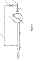
- the arrangement shown in Fig. 1 is a prior art setup for a TEPSA process showing how it is currently used in practise. As can be seen, the arrangement does not use (only) one single heater for providing hot regeneration gas to the adsorbent beds, but instead uses heaters in close proximity to the regeneration gas inlets of each of the adsorbent vessels, an individual heater being present for the heating of the regeneration gas for each vessel.
- Fig. 1 two heaters 62, 62' are located in close proximity to each adsorbent vessel 20, 22.
- the integrity of the heat pulse to the adsorbent bed is ensured.
- the arrangement is complicated as every adsorbent vessel 20, 22 needs to be equipped with a separate heater which in turn means higher investment costs.
- Fig. 2 shows configuration which can be used in the present invention.
- Regeneration gas originates from the regeneration gas source.
- a single heater 62 is located in the regeneration gas line and is isolated through two valves 58 and 60 which control the route of the regeneration gas.
- the regeneration gas can thereby either be directed through the heater 62 via open valve 60 or can by-pass the heater with valve 60 closed and with valve 58 open.
- the line exiting the heater in the direction to the adsorber vessel (depicted as to "adsorbent vessels, 20, 22"; cf. Fig. 3 ) is joined with the by-pass line for cool regeneration gas controlled via valve 58.
- the line length X to said junction is depicted in Fig.
- Fig. 3 depicts in addition the line length Y (Distance Y), whereby the regeneration gas inlet (only depicted as "to adsorbent vessels, 20, 22") is not shown.
- the line length Y is the distance between the aforementioned junction (i.e. the junction of the line exiting the heater in the direction to the adsorber vessel with the length X and the by-pass line for cool regeneration gas controlled via valve 58) and the regeneration gas inlet of the adsorber vessels. It must be noted that the length Y is measured for each line leading from said junction to the respective adsorber vessel individually.
- the details of said "hot standby" heater arrangement are also shown in Fig. 3 .
- air to be purified (the feed stream) is supplied to a main air compressor system 10 at an inlet 12 in which it is compressed by a multi-stage compressor with inter and after cooling by heat exchange with water.
- the cooled compressed air is supplied to an inlet manifold 14 containing inlet control valves 16 and 18 to which is connected a pair of adsorbent bed containing vessels 20 and 22.
- the inlet manifold is bridged downstream of the control valves 16 and 18 by a venting manifold 24 containing venting valves 26, 28 which serve to close and open connections between the upstream end of respective adsorbent vessels 20 and 22 and a vent 30 via a silencer 32.
- Each of the two adsorbent beds 20 and 22 contains at least two adsorbents.
- the feed end adsorbent is designated by the numeral 34, 34' in respective beds and the product end adsorbent by the numeral 36, 36'.
- the apparatus has an outlet 38 connected to the downstream ends of the two adsorbent vessels 20, 22 by an outlet manifold 40 containing outlet control valves 42, 44.
- the outlet manifold 40 is bridged by a regenerating gas manifold 46 containing regenerating gas control valves 48 and 50. Upstream from the regenerating gas manifold 46, a line 52 containing a control valve 54 also bridges across the outlet manifold 40. An inlet for regenerating gas is provided at 56 which through control valves 58 and 60 is connected to pass regeneration gas either through a heater 62 or via a by-pass line 64 to the regenerating gas manifold 46.
- valves may be controlled by suitable programmable timing and valve operating means as known in the art (not illustrated).
- air is compressed in the main air compressor system 10 and is fed to the inlet manifold 14 and passes through one of the two vessels containing adsorbent.
- valve 18 in the inlet manifold will just have been closed to cut-off vessel 22 from the feed of air for purification.
- Valve 44 will just have closed also.
- valves 48, 50, 54, and 26 are closed. Bed 20 is thus on-line and bed 22 is to be regenerated.
- valve 28 is opened and once the pressure in the vessel 22 has fallen to a desired level, valve 28 is kept open whilst valve 50 is opened to commence a flow of regenerating gas.
- the regenerating gas will typically be a flow of dry, CO 2 -free nitrogen obtained from the air separation unit cold box, possibly containing small amounts of argon, oxygen and other gases, to which the air purified in the apparatus shown is passed.
- Valve 60 is closed and valve 58 is opened so that the regenerating gas is heated to a temperature of e.g. 70 °C before passing into the vessel 22.
- the regenerating gas enters the vessel 22 at the selected elevated temperature, it is very slightly cooled by giving up heat to desorb carbon dioxide from the upper, downstream adsorbent portion 36' in the vessel. Since the heat pulse is retained in the system, the exit purge gas emerges from the vent outlet 30 in a cooled state. Progressively, a heat wave moves through the upper adsorbent 36' as the carbon dioxide is cleared. After a desired period, whilst the heat pulse is part way through the upper adsorbent 36', valve 58 is closed and valve 60 is opened so that the flow of regenerating gas now becomes cool. The cooled regenerating gas displaces the heat pulse further through the upper adsorbent 36'.
- valve 50 may be closed to end the flow of regenerating gas and valve 54 may be opened to displace nitrogen from the adsorbent and, after the closing of valve 28, to repressurise the vessel 22 with purified air. Thereafter, valve 54 may be closed and valves 18 and 44 may be opened to put the vessel 22 back on line.
- Residual heat left in bed may be removed by the purified air as a temperature pulse which can be removed in a downstream heat exchanger.
- the vessel 20 may then be regenerated in a similar manner and the whole sequence continued with the vessels being on-line, depressurising, regenerating, repressurising, and going back on-line in phased cycles of operation.
- the heat pulse during regeneration does not penetrate as far as the boundary of the portion of the adsorbent into which water is adsorbed. This will lie somewhere within the region 34, 34' below the boundary with the region 36, 36' shown in the drawings.
- the actual proportions of the regions 34, 34' and 36, 36' are dependent on the operating conditions, e.g. feed pressure, feed temperature, cycle time and purge/air ratio.
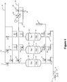
- Fig. 4 shows a three adsorbent vessel inventive solution for the "hot stand-by” application, whereby, instead of using three separate heaters, a single heater is installed and “shared” at a suitable position between the adsorber vessels.
- Such an arrangement brings much simplicity and is more sustainable as it also saves energy, maintenance time and can be run more efficiently.
- the arrangement "with hot stand-by heater” corresponds to that shown in Fig. 3 .
- the experiments were performed in a TEPSA arrangement according to Fig. 2 whereby a "hot stand-by heater” corresponding to that of Fig. 3 was used.
- all of the regeneration gas is passed through the heater, which accordingly must be switched off after the heating of the regeneration gas needed in the first regeneration phase and is switched on again only at the beginning of the next first regeneration phase to heat up regeneration gas to the desired temperature.
- the test arrangement used for the experiments had a maximum available flow of 1500 Nm 3 hr -1 .
- the pipes and heater duty were 4" and 24 kW, respectively.
- the flow was measured upstream of the heater using an elbow flow meter and the pressure was measured upstream and downstream of the heater.
- the air flow rate describes the feed flow rate of the feed stream to TEPSA vessels.
- the purge flow rate was used.
- the air flow rate describes the purge flow rate.
- the purge flow rate remains the same for both heating and cooling steps. In the hot stand-by arrangement, the flow through the test arrangement is reduced to zero to mimic the stagnant gas in the heater.
- ⁇ T is defined as the difference between the feed stream to TEPSA vessels temperature and the regeneration temperature at the top of the adsorbent bed.
- the required ⁇ T is 30°, therefore, the achieved ⁇ T during experiments must be at least 30°C. This means for all examples that the required ⁇ T of 30°C is the minimum temperature increase in stream temperature which must be achieved to meet the regeneration requirements. This requirement is met by all examples.
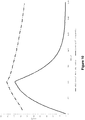
- CE1, cf. diagram of Fig. 5 shows the temperature pulse progression exiting a heater from the cold position whereby no "hot stand-by" is applied.
- the heater is installed in the common line providing regeneration gas from a regeneration gas source to the TEPSA process.
- the heating time is 10 minutes.
- the results are shown in Fig. 6 .
- the rate of decrease of the stream temperature during the cooling step is less at distances further away from the heater (cf. Fig. 6 ).
- the difference is such that for a short period of time after the heater being switched off, the stream temperature furthest from the heater is hotter than just after the heater. This difference can be as significant as 5°C, i.e. at a point in time during the cooling step.
- the stream temperature at 9 m was 5°C hotter than the stream temperature at 1 m.
- a "hot stand-by" set up for the heater was used and insulation has been applied.
- the insulation material applied is recycled fibre.
- the downstream pipe was kept warm whilst the cold purge was directed through the by-pass by closing valve 58 and opening valve 60 (cf. Fig. 3 ).
- Table 3 The experimental conditions applied for IE2 are depicted in Table 3 below.
- Table 3 Experimental conditions for Inventive Examples 2.
- X 1 m
- IE1 when comparing it to CE1 the temperature drop at the start of the heating process immediately exiting the heater, i.e. the difference between the highest and lowest temperature value during said first regeneration phase is reduced from 45 °C to about 12 °C. A similar effect is shown in comparison to CE2.
- the conditions and arrangement applied for IE1 allow a much more significant quantity of high grade heat to be introduced to the TEPSA process. Besides, higher peak temperatures can be obtained. Furthermore, less energy is necessary to reach the peak temperature as the difference between the highest and lowest temperature value during the first regeneration phase is significantly reduced.
Abstract
Description
- The present invention relates to a Thermally Enhanced Pressure Swing Adsorption (TEPSA) process for pre-purification of air prior to cryogenic distillation, applying a single heater and at least two adsorber vessels. The invention further relates to an apparatus for use in such TEPSA process.
- It is regularly necessary to remove gas components from a gas stream by adsorption on a solid adsorbent. In particular, pre-purifying steps are commonly used when performing cryogenic air separation processes. Thereby, periodic regeneration of the adsorbent is necessary as such removed gas components may be of intrinsic value or they may be contaminating gas components in the gas mixture.
- In such processes the gas is conventionally fed in contact with a solid adsorbent contained in an adsorber vessel to adsorb the component or components to be removed and these gradually build-up in the adsorbent. The concentration of the removed component or components in the adsorbent gradually rises and if the process is continued for a sufficient period, the adsorbed components will break through the downstream end of the adsorbent bed. Before this occurs, it is necessary to regenerate the adsorbent.
- For performing pre-purifying steps different processes such as Thermal Swing Adsorption (TSA), Pressure Swing Adsorption (PSA) and Thermally Enhanced Pressure Swing Adsoprtion (TEPSA) are applied.
- In a PSA process the desorption is done by stopping the flow into the adsorbent of gas to be treated, depressurizing the adsorbent and, usually, by passing a flow of regenerating gas low in its content of the component adsorbed on the bed through the bed counter-current to the product feed direction.
- The TSA process is commonly used to pre-purify air upstream of a cryogenic air separation unit (ASU). The TSA process is characterized by high temperature regeneration of the adsorption process, typically well above 100 °C, and a long hot regeneration period. Since the heat flux associated with TSA processes is intense and lengthy, degradation in heat pulse quality has minimal impact on the TSA desorption process. The heat provided to a TSA process, by the heater, is primarily used to desorb the strongly adsorbed component, namely water, which has high heat of adsorption.
- A variant of the TSA process is the TEPSA process described for example in
U.S. Pat. No. 5,614,000 . TEPSA is a low temperature regeneration process with temperatures typically below 100 °C and only with short heating. Contrary to the TSA process, the heat provided by a heater is used to remove the "least strongly" adsorbed contaminates, namely CO2. The heat flux associated with TEPSA processes can be described as weak, so even small heat losses on its journey towards the adsorbent bed can immensely degrade the quality of the heat carried by the heat pulse. - This is in contrast to the conventional TSA processes being dominated by high temperatures for regeneration of well above 100 °C and periods of hot regeneration of well above 10 minutes. Due to the more drastic conditions of TSA processes the position of the heater within reasonable distance (e.g. 20 m or more away from the adsorber vessel) has only little influence on the regeneration process, c.f.
U.S. Pat. No. 9,108,145 - In
U.S. Pat No. 5,614,000 as well asU.S. Pat. No. 8,734,571 an apparatus configuration for TEPSA is described including only a single external heater for providing hot regeneration gas. Such a configuration, only including one external heater not being located in close proximity to the adsorbent vessels, has the disadvantage that heat losses occur easily, thereby degrading the quality of the heat pulse (which ideally has rectangular shape), sent to the adsorbent bed immensely. - This is the reason why in the practise of TEPSA processes so far such a configuration has not been applied, but rather configurations such as described in
U.S. Pat. No. 7,066,986 are used. In this document, a two bed heater arrangement for TEPSA processes is disclosed wherein every adsorbent vessel has a separate heater. The heaters are arranged in a way that every adsorbent vessel is equipped with a separate heater element being located in the inlet nozzle of the adsorber vessel. By such a TEPSA arrangement described above disadvantages such as heat loss, varying quality of the heat pulse etc. can be minimized. Besides, the distance between the heater and the adsorbent bed is minimised, maintaining the quality of the heat pulse prior to contact with the adsorbent bed. - The problem with a heater arrangement as described by
U.S. Pat. No. 7,066,986 is that multiple heaters have to be used, that is, one for each adsorbent vessel. Such an arrangement causes increased maintenance efforts due to the fact that a multitude of heaters is necessary and that these heaters have to be positioned in close contact with the adsorbent vessel. Furthermore, due to the fact that the heaters are contained in the inlet nozzles of the adsorbent vessels they hinder the implementation of more complicated vessel arrangements due to their bulkiness. In addition, a multitude of heaters has cost adverse effects due to an increase in material and energetic input. Furthermore, maintenance costs are also higher. - Thus, there is the need of an improved TEPSA process. The present invention aims to overcome the disadvantages of the TEPSA processes known in the art, and particularly aims to provide a process requiring a less complicated and expensive apparatus configuration which concurrently provides a stable heat pulse to the adsorbent bed(s).
- Thus, the present invention aims to process intensification for operating low regeneration temperature TEPSA, related to the purification of air prior to cryogenic separation of air, to simplify and reduce the cost of the current process.
- Moreover, the present invention relates to the provision of an apparatus which can be used for such TEPSA processes.
- The present invention is based on the finding that above problems can be overcome by a TEPSA process using a single heater and at least two separate adsorbent vessels whereby the temperature difference between the highest and lowest temperature value during the first regeneration phase at the regeneration gas inlet of the adsorption vessel is 20 °C or lower.
- The present invention therefore provides in a first aspect a temperature enhanced pressure swing adsorption (TEPSA) process for removing at least two components including a less strongly adsorbed component and a more strongly adsorbed component from a gas mixture, said process comprising using one single heater and at least two adsorber vessels, in each of which repeated cycles comprising an adsorption phase and subsequent regeneration phases are performed as follows:
- in the adsorption phase said gas mixture is passed in a first direction through an adsorbent bed contained in the adsorber vessel, so that said gas mixture is purified by the adsorption of said at least two components in the adsorbent bed,
- in a first regeneration phase a hot regeneration gas having a target temperature which is selected to be any temperature in the range from 20 °C to 100 °C is passed through the adsorbent bed in a flow direction opposite to the flow direction during the adsorption phase, and
- in a second regeneration phase a cool regeneration gas having a target temperature which is selected to be any temperature in the range from 5 °C to 65 °C is passed through the adsorbent bed in a flow direction opposite to the flow direction during the adsorption phase,
- wherein
- the hot regeneration gas is provided to each of the adsorber vessels by passing regeneration gas from the source of the regeneration gas to said heater where it is heated up, and passing the hot regeneration gas leaving the heater to the respective vessel, and
- the cool regeneration gas is provided to each of the adsorber vessels by directing regeneration gas from the source to the respective vessel by-passing the heater, and
- the temperature difference between the highest and lowest temperature value during said first regeneration phase at the regeneration gas inlet of the adsorber vessel is 20 °C or lower.
- The TEPSA process according to the invention has various advantages which are obtained by the specific configuration as described herein. The heat loss during regeneration phase is kept at a minimum and a stable and sharp (more rectangular shaped) heat pulse can be generated and passed over the adsorbent beds during the first regeneration phase. Besides, maintenance efforts can be reduced significantly as only one heater is necessary for the process, and energy reduction can be achieved making the process more economic and more sustainable.
- Usually, the process of the invention is carried out so that in the different adsorbent beds alternatingly adsorption and regeneration is carried out, i.e. where two adsorbent vessels are used, in
vessel 1 adsorption and simultaneously invessel 2 regeneration take place. - In case more than two adsorbent beds are used, for example, three or four, still one single heater may be used for heating up the regeneration gas used in the first regeneration phase of each of the adsorbent vessels, as this phase is comparatively short in TEPSA processes so that heated gas may be alternatingly provided to each of the vessels.
- In any case, it is important for the claimed process that the cool regeneration gas used in the second regeneration phase is not passed over a, possibly switched-off, heater but by-passes the heater.
- In a second aspect the present invention provides a process according to the first aspect wherein the temperature difference between the highest and lowest temperature value during said first regeneration phase at the regeneration gas inlet of the adsorber vessel is 15 °C or lower.
- In a third aspect, the present invention provides a process according to any one of the previous aspects wherein the hot regeneration gas in the first regeneration phase has a target temperature which is selected to be any temperature in the range from 20 °C to 70 °C.
- In a fourth aspect the present invention provides a process according to any one of the preceding aspects, wherein the cool regeneration gas in the second regeneration phase has a target temperature which is selected to be any temperature in the range from 10 °C to 55 °C.
- In a fifth aspect the present invention provides a process according to any one of the preceding aspects, wherein the difference of the target temperatures of the hot regeneration gas in the first regeneration phase and the cool regeneration gas in the second regeneration phase is 15 °C or more.
- In sixth aspect, the present invention provides a process according to any one of the preceding aspects, wherein the peak temperature of the hot regeneration gas in the first regeneration phase is 45 °C or more.
- In an seventh aspect, the present invention provides a process according to any one of the preceding aspects, wherein the first regeneration phase takes place for 20 min or less.
- In an eigth aspect, the present invention provides a process according to any one of the preceding aspects, wherein the second regeneration phase takes place for 80 min or less.
- In a ninth aspect, the present invention provides a process according to any one of the preceding aspects, wherein the overall regeneration cycle time (on-line time) is 120 min or less.
- In a tenth aspect the present invention provides an apparatus for use in the TEPSA process according to any one of the preceding aspects comprising one single heater and at least two adsorber vessels, wherein each adsorber vessel comprises
- an inlet for a gas mixture to be purified and an outlet for purified gas separated by a flow path including a flow chamber containing an adsorbent bed,
- an inlet and an outlet for regeneration gas separated by a flow path including said flow chamber,
- the apparatus further comprising
- lines connecting the source of the gas mixture to be purified with the inlets for the gas mixture of each adsorber vessel,
- a line connecting the heater with the source of regeneration gas,
- lines connecting the heater with the inlet for regeneration gas of each adsorber vessel, and
- lines connecting the source of the regeneration gas with the inlet for regeneration gas of each absorber vessel which by-pass the heater,
- wherein in operation of the apparatus
- hot regeneration gas is provided to each of the adsorber vessels during a first regeneration phase by passing regenerating gas from the source to the heater, heating it up, and passing the heated regeneration gas to the regeneration gas inlet of the respective adsorber vessel so that the temperature difference between the highest and lowest temperature value during said first regeneration phase at the regeneration gas inlet of the respective adsorber vessel is 20 °C or lower, and
- cool regeneration gas is provided to each of the adsorber vessels during a second regeneration phase by directing regeneration gas from the source to the respective vessel by-passing the heater.
- In an eleventh aspect the present invention provides an apparatus according to the tenth aspect, wherein a single line for heated regeneration gas leaves the heater which is split up into lines leading to each of the adsorber vessel inlets for regeneration gas individually.
- In a twelfth aspect the present invention provides an apparatus according to the eleventh aspect, wherein the single line from the heater is joined with a single line from the regeneration gas source which has by-passed the heater to form a single, common regeneration gas line before this common line is split to lines leading to each of the adsorber vessels inlets for regeneration gas individually.
- In a thirteenth aspect the present invention provides an apparatus according to the twelfth aspect, wherein the length X of the single line from the heater to the junction with the line by-passing the heater is between 1 m to 9 m.
- In a fourteenth aspect the present invention provides an apparatus according to the twelfth or thirteenth aspect, wherein the length Y of the line between the junction of the single line from the heater with that by-passing the heater and the inlet for the regeneration gas of each adsorber vessel is not more than 6 m.
- In a fifteenth aspect the present invention provides an apparatus according to the tenth to fourteenth aspect, wherein a single line from the regeneration gas source is split up to a line which leads to the heater and a line which by-passes the heater.
- In a sixteenth aspect the present invention provides an apparatus according to the twelfth to fifteenth aspect, wherein the line along length X of the single line from the heater to the junction with the line by-passing the heater is insulated.
- In the process of the invention, the repeated cycle of operation comprises an adsorption phase, during which a feed gas mixture stream in a feed direction at a first pressure and a first temperature is in contact with a solid adsorbent capable of adsorbing a first component to be adsorbed more strongly and a second component to be adsorbed less strongly so that said first component is adsorbed in an upstream portion of said adsorbent and said second component is adsorbed principally in a more downstream portion of said adsorbent.
- After the adsorption phase, the feed gas stream is halted and the gas in contact with the adsorbent is depressurized to a second, lower pressure.
- After depressurization, the regeneration phases are carried out as described above. During the first regeneration phase, mainly the less strongly adsorbed component in the more downstream portion (relating to the flow of the gas mixture during the adsorption phase) is desorbed and in the second regeneration phase mainly the more strongly adsorbed second component in the upstream portion of the adsorbent is desorbed.
- In the process according to the present invention the temperature difference between the highest and lowest temperature value during the first regeneration phase at the regeneration gas inlet of the adsorption vessel is 20°C or lower. This is to ensure a high quality of the heat pulse during the first regeneration phase.
- Preferably, said temperature difference is 18 °C or lower, more preferably 15 °C or lower, more preferably 13° C or lower and most preferably 11 °C or lower.
- Usually, the temperature difference between the highest and lowest temperature value during the first regeneration phase at the regeneration gas inlet of the adsorption vessel is 5 °C or higher.
- This temperature difference is determined by continuously measuring the temperature at the regeneration gas inlet of the adsorption vessel during the entire first regeneration phase and subtracting the highest from the lowest measured temperature value.
- Preferably, in the process according to the present invention the target temperature of the hot regeneration gas in the first regeneration phase is selected to be any temperature in the range from 20 °C to 90 °C, preferably 20 °C to 80 °C, more preferably 20 °C to 70 °C, still more preferably 30 °C to 70 °C, still more preferably 30 °C to 65 °C and most preferably 30 °C to 60 °C.
- In the process according to the invention the target temperature of the cool regeneration gas in the second regeneration phase is selected to be any temperature in the range from 10° C to 65 °C, preferably 15 °C to 65 °C, more preferably 15 °C to 60 °C and most preferably 15 °C to 55 °C.
- The target temperature is the maximum temperature in a regeneration phase immediate to the adsorbent bed top surface.
- Preferably, the difference of the target temperatures of the hot regeneration gas in the first regeneration phase and the cool regeneration gas in the second regeneration phase is 15 °C or more, more preferably is 20 °C or more.
- The peak temperature, i.e. the highest measured temperature, of the hot regeneration gas at the regeneration gas inlet of the adsorber vessel in the first regeneration phase is 45 °C or more.
- As mentioned, the period during which heated regeneration gas is passed over the adsorbent bed is rather short in TEPSA processes. Thus, in the process according to the present invention the first regeneration phase takes place for 30 min or less, preferably 25 min or less, preferably 20 min or less, more preferably 15 min or less, and most preferably 12 min or less.
- Usually, the duration of the first regeneration phase is 5 min or more, preferably 10 min or more.
- In the process according to the present invention the second regeneration phase preferably takes place for 90 min or less, preferably 80 min or less, more preferably 70 min or less, still more preferably 55 min or less, still more preferably 45 min or less, still more preferably 30 min or less, and most preferably 25 min or less.
- Usually, the duration of the second regeneration phase is 5 min or more, preferably 10 min or more, and more preferably 15 min or more.
- In the process according to the present invention the overall regeneration cycle time, i.e. including all regeneration phases (on-line time), is 120 min or less, preferably 105 min or less, more preferably 90 min or less, still more preferably 75 min or less, still more preferably 60 min or less, and most preferably 45 min or less.
- Usually, the overall regeneration cycle time is 10 min or more, preferably 15 min or more, and more preferably 30 min or more.
- Preferably, in the process of the invention the heater, and optionally also the downstream line with the "critical length X" as described below, are always kept warm. This is done to improve the heat pulse integrity during the first regeneration phase. Preferably the downstream line with the "critical length X" is insulated.
- Preferably, in the process of the invention also the downstream line with the "length Y" as described below is insulated. This is done to improve the heat pulse integrity during the first regeneration phase. Insulation also serves personal protection.
- Preferably, the temperature in the heater does not fall 20°C or more, preferably 15°C or more, more preferably 10°C or more, and most preferably 5°C or more below the target temperature of the first regeneration phase during the entire process. This may be achieved by appropriate means, such as switching off the heater only during short periods or not switching it off at all during the process, and/or by application of a line (normal piping) arrangement enabling the heater to remain at, or close to, normal operating temperature all the time.
- Further preferred, the temperature in the downstream line with length X at the opposite end to the heater does not fall 25°C or more, preferably 20°C or more, more preferably 15°C or more, and most preferably 10°C or more below the target temperature of the first regeneration phase during the entire process.
- In a preferred embodiment, in the process of the invention the gas mixture to be purified is air.
- Further preferred, the less strongly adsorbed component to be adsorbed from the gas mixture is carbon dioxide.
- Preferably the CO2 concentration in the gas mixture to be purified is from 50 to 2000 ppm, preferably from 100 to 1500 ppm, more preferably from 100 ppm to 1000 ppm, still more preferably from 200 to 800 ppm, and most preferably from 300 to 600 ppm.
- The gas mixture to be purified may also contain N2O, if present the concentration of N2O is from 100 to 1000 ppb, preferably from 100 to 900 ppb, more preferably from 200 to 700 ppb, and most preferably from 300 to 500 ppb.
- Still further preferred, the more strongly adsorbed component to be adsorbed from the gas mixture is water.
- In an embodiment of the invention, the flow of the gas mixture to be purified during the adsorption phase is from 250 to 200,000 Nm3hr-1, preferably is from 250 to 175,000 Nm3hr-1, more preferably from 250 to 125,000 Nm3hr-1, still more preferably from 350 to 100,000 Nm3hr-1, still more preferably from 350 to 50,000 Nm3hr-1, and most preferably from 500 to 20,000 Nm3hr-1. In a further embodiment, the flow of the regeneration gas during the first and/or second regeneration phase is from 250 to 150,000 Nm3hr-1, preferably is from 250 to 125,000 Nm3hr-1, still more preferably from 250 to 100,000 Nm3hr-1, still more preferably from 250 to 50,000 Nm3hr-1, still more preferably from 250 to 15,000 Nm3hr-1, and most preferably from 500 to 15,000 Nm3hr-1.
- The purge/air ratio (P/A ratio) is from 0.1 to 0.9, preferably from 0.2 to 0.8, more preferably from 0.2 to 0.7, still more preferably from 0.25 to 0.6, and most preferably from 0.3 to 0.5.
- The pressure of the gas mixture to be purified (the feed stream) is from 1 to 50 bara, preferably from 2 to 45 bara, still more preferably from 3 to 40 bara, still more preferably from 3.5 to 30 bara, still more preferably from 3.5 to 20 bara, and most preferably from 4 to 10 bara.
- Further preferred embodiments of the process of the invention involve the use of the apparatus as described hereinbelow in any of the described embodiments.
- In another aspect, the present invention provides an apparatus for use in the TEPSA process described in any of the above described embodiments comprising one single heater and at least two adsorber vessels, wherein each adsorber vessel comprises
- an inlet for a gas mixture to be purified and an outlet for purified gas separated by a flow path including a flow chamber containing an adsorbent bed,
- an inlet and an outlet for regeneration gas separated by a flow path including said flow chamber,
- lines connecting the source of the gas mixture to be purified with the inlets for the gas mixture of each adsorber vessel,
- a line connecting the heater with the source of regeneration gas
- lines connecting the heater with the inlet for regeneration gas of each adsorber vessel, and
- lines connecting the source of the regeneration gas with the inlet for regeneration gas of each absorber vessel which by-pass the heater,
- hot regeneration gas is provided to each of the adsorber vessels during a first regeneration phase by passing regenerating gas from the source to the heater, heating it up, and passing the heated regeneration gas to the regeneration gas inlet of the respective adsorber vessel so that the temperature difference between the highest and lowest temperature value during said first regeneration phase at the regeneration gas inlet of the respective adsorber vessel is 20 °C or lower, and
- cool regeneration gas is provided to each of the adsorber vessels during a second regeneration phase by directing regeneration gas from the source to the respective vessel by-passing the heater.
- In a preferred embodiment of the apparatus according to the invention a single line for heated regeneration gas leaves the heater which is split up into lines leading to each of the adsorber vessel inlets for regeneration gas individually.
- Further preferred, the single line from the heater is joined with a single line from the regeneration gas source which has by-passed the heater to form a single, common regeneration gas line before this common line is split to lines leading to each of the adsorber vessels inlets for regeneration gas individually.
- In a particularly preferred embodiment of the invention, the length X of the single line from the heater to the junction with the line by-passing the heater is between 1 m to 9 m, preferably between 1 m to 6 m.
- By keeping the "critical length X" of the line between the heater and the junction of the line from the heater with that of the line by-passing the heater between 1 m to 9 m, an especially sharp heat pulse can be provided to the adsorbent beds during the first regeneration phase.
- As mentioned above, it is preferred that in the process of the invention the heater and possibly also the downstream line with the "critical length X" as described above are always kept warm. Therefore, it is preferred that the line along length X is insulated.
- In a preferred embodiment of the apparatus of the invention a single line from the regeneration gas source is split up to a line which leads to the heater and a line which by-passes the heater.
- In a preferred embodiment of the apparatus of the invention, the total length of the line between the junction of the single line from the heater with that by-passing the heater and the inlet for the regeneration gas of each adsorber vessel, "length Y", is not more than 6 m, more preferably is not more than 4 m, and most preferably is not more than 3 m.
- The apparatus according to the invention has various advantages. The application of a single heater not being directly connected to or contained in the inlet nozzle of the adsorber vessel allows a more simple arrangement. Such a simple and more economic arrangement also allows more efficient maintenance thereby saving maintenance time and also maintenance costs. Furthermore, as the temperature of the heater will not reduce to ambient more square temperature profiles when the flow is rerouted over the heater and to the adsorbent vessels can be achieved with the inventive apparatus. The decline of the line temperature is decreased and, hence, sharper temperature profiles can be obtained through the inventive apparatus.
-
-
Fig. 1 : Two adsorption vessel (2 bed) containing TEPSA arrangement with integrated heaters as known in the art; -
Fig. 2 : Two adsorption vessel (2 bed) containing TEPSA configuration with external heater and by-pass line; -
Fig. 3 : Simplified "hot stand-by" heater arrangement with the depiction of the line length "X" (Distance X) and the line length "Y" (Distance Y); -
Fig. 4 : Three adsorption vessel (3 bed) containing TEPSA arrangement with external heater and by-pass line; -
Fig. 5 : Diagram showing the TEPSA regeneration stream temperature profile without a "hot stand-by" heater arrangement with X = 1 m; -
Fig. 6 : Comparison of diagrams showing TEPSA regeneration stream temperature profiles without a "hot stand-by" heater arrangement with X = 1 m and X = 9 m; -
Fig. 7 : Comparison of diagrams showing a "hot stand-by" regeneration and stand-by profile with insulation with X = 9 m and a "hot stand-by" regeneration and stand-by profile with insulation with X = 1 m. -
Fig. 8 : Comparison of diagrams showing a "hot stand-by" regeneration and stand-by profile without insulation with X = 9 m and a "hot stand-by" regeneration and stand-by profile without insulation with X = 1 m. -
Fig. 9 : Comparison of diagrams showing a "hot stand-by" regeneration and stand-by profile with insulation with X = 1 m, a "hot stand-by" regeneration and stand-by profile without insulation with X = 1 m and a regeneration stream temperature profile without a "hot stand-by" heater arrangement and without insulation with X = 1 m. -
Fig. 10 : Comparison of diagrams showing a "hot stand-by" regeneration profile with X = 9 m with insulation versus the regeneration stream temperature profile without a "hot stand-by" heater arrangement with X = 9 m. -
Fig. 11 : Comparison of diagrams showing a "hot stand-by" regeneration profile with X = 9 m with insulation versus the regeneration stream temperature profile without a "hot stand-by" heater arrangement with X = 1 m. - The arrangement shown in
Fig. 1 is a prior art setup for a TEPSA process showing how it is currently used in practise. As can be seen, the arrangement does not use (only) one single heater for providing hot regeneration gas to the adsorbent beds, but instead uses heaters in close proximity to the regeneration gas inlets of each of the adsorbent vessels, an individual heater being present for the heating of the regeneration gas for each vessel. - Thus, in
Fig. 1 twoheaters 62, 62' are located in close proximity to eachadsorbent vessel adsorbent vessel -
Fig. 2 shows configuration which can be used in the present invention. Regeneration gas originates from the regeneration gas source. Asingle heater 62 is located in the regeneration gas line and is isolated through twovalves heater 62 viaopen valve 60 or can by-pass the heater withvalve 60 closed and withvalve 58 open. In a distance X, the line exiting the heater in the direction to the adsorber vessel (depicted as to "adsorbent vessels, 20, 22"; cf.Fig. 3 ) is joined with the by-pass line for cool regeneration gas controlled viavalve 58. The line length X to said junction is depicted inFig. 3 as distance X and is always kept warm, for example by means including insulation of said line.Fig. 3 depicts in addition the line length Y (Distance Y), whereby the regeneration gas inlet (only depicted as "to adsorbent vessels, 20, 22") is not shown. The line length Y is the distance between the aforementioned junction (i.e. the junction of the line exiting the heater in the direction to the adsorber vessel with the length X and the by-pass line for cool regeneration gas controlled via valve 58) and the regeneration gas inlet of the adsorber vessels. It must be noted that the length Y is measured for each line leading from said junction to the respective adsorber vessel individually. The details of said "hot standby" heater arrangement are also shown inFig. 3 . - According to
Fig. 2 air to be purified (the feed stream) is supplied to a mainair compressor system 10 at aninlet 12 in which it is compressed by a multi-stage compressor with inter and after cooling by heat exchange with water. The cooled compressed air is supplied to aninlet manifold 14 containinginlet control valves bed containing vessels control valves manifold 24 containing ventingvalves respective adsorbent vessels vent 30 via asilencer 32. Each of the twoadsorbent beds - The apparatus has an
outlet 38 connected to the downstream ends of the twoadsorbent vessels outlet manifold 40 containingoutlet control valves - The
outlet manifold 40 is bridged by a regeneratinggas manifold 46 containing regeneratinggas control valves gas manifold 46, aline 52 containing acontrol valve 54 also bridges across theoutlet manifold 40. An inlet for regenerating gas is provided at 56 which throughcontrol valves heater 62 or via a by-pass line 64 to the regeneratinggas manifold 46. - The operation of the valves may be controlled by suitable programmable timing and valve operating means as known in the art (not illustrated).
- In operation air is compressed in the main
air compressor system 10 and is fed to theinlet manifold 14 and passes through one of the two vessels containing adsorbent. Starting from a position in which air is passing throughopen valve 16 toadsorbent vessel 20, and throughopen valve 42 to theoutlet 38,valve 18 in the inlet manifold will just have been closed to cut-offvessel 22 from the feed of air for purification.Valve 44 will just have closed also. At thisstage valves Bed 20 is thus on-line andbed 22 is to be regenerated. - To commence depressurisation of
bed 22,valve 28 is opened and once the pressure in thevessel 22 has fallen to a desired level,valve 28 is kept open whilstvalve 50 is opened to commence a flow of regenerating gas. The regenerating gas will typically be a flow of dry, CO2 -free nitrogen obtained from the air separation unit cold box, possibly containing small amounts of argon, oxygen and other gases, to which the air purified in the apparatus shown is passed.Valve 60 is closed andvalve 58 is opened so that the regenerating gas is heated to a temperature of e.g. 70 °C before passing into thevessel 22. Although the regenerating gas enters thevessel 22 at the selected elevated temperature, it is very slightly cooled by giving up heat to desorb carbon dioxide from the upper, downstream adsorbent portion 36' in the vessel. Since the heat pulse is retained in the system, the exit purge gas emerges from thevent outlet 30 in a cooled state. Progressively, a heat wave moves through the upper adsorbent 36' as the carbon dioxide is cleared. After a desired period, whilst the heat pulse is part way through the upper adsorbent 36',valve 58 is closed andvalve 60 is opened so that the flow of regenerating gas now becomes cool. The cooled regenerating gas displaces the heat pulse further through the upper adsorbent 36'. - Whilst the upper adsorbent has been thus regenerated by TSA, the cool regenerating gas has continued to flow through the lower, upstream adsorbent 34' and by virtue of its reduced pressure has desorbed water and carbon dioxide from the upstream adsorbent 34' by PSA. At the end of the allotted regeneration period,
valve 50 may be closed to end the flow of regenerating gas andvalve 54 may be opened to displace nitrogen from the adsorbent and, after the closing ofvalve 28, to repressurise thevessel 22 with purified air. Thereafter,valve 54 may be closed andvalves vessel 22 back on line. Residual heat left in bed may be removed by the purified air as a temperature pulse which can be removed in a downstream heat exchanger. Thevessel 20 may then be regenerated in a similar manner and the whole sequence continued with the vessels being on-line, depressurising, regenerating, repressurising, and going back on-line in phased cycles of operation. - In accordance with the invention, the heat pulse during regeneration does not penetrate as far as the boundary of the portion of the adsorbent into which water is adsorbed. This will lie somewhere within the
region 34, 34' below the boundary with theregion 36, 36' shown in the drawings. The actual proportions of theregions -
Fig. 4 shows a three adsorbent vessel inventive solution for the "hot stand-by" application, whereby, instead of using three separate heaters, a single heater is installed and "shared" at a suitable position between the adsorber vessels. Such an arrangement brings much simplicity and is more sustainable as it also saves energy, maintenance time and can be run more efficiently. - Simulations were performed to test the integrity (shape) of the heat pulse sent to the adsorber vessels during the first regeneration phase in arrangements with and without "hot stand-by".
- The arrangement "with hot stand-by heater" corresponds to that shown in
Fig. 3 . The experiments were performed in a TEPSA arrangement according toFig. 2 whereby a "hot stand-by heater" corresponding to that ofFig. 3 was used. In the arrangement "without hot stand-by heater" all of the regeneration gas is passed through the heater, which accordingly must be switched off after the heating of the regeneration gas needed in the first regeneration phase and is switched on again only at the beginning of the next first regeneration phase to heat up regeneration gas to the desired temperature. - Besides, experiments were conducted with a "hot stand-by" heater arrangement with and without insulated piping.
- The test arrangement used for the experiments had a maximum available flow of 1500 Nm3 hr-1. The pipes and heater duty were 4" and 24 kW, respectively.
- The flow was measured upstream of the heater using an elbow flow meter and the pressure was measured upstream and downstream of the heater.
- Thermocouples were placed:
- a) upstream of the heater, to measure the temperature of the gas in order to measure the temperature increase across the heater;
- b) at an ambient location, for heat loss calculations; and
- c) at 0.2 m, 1 m, and then at 1 m intervals up to 9 m, allowing for simultaneous multiple temperature versus time curves at increasing distances away from the heater.
- The air flow rate describes the feed flow rate of the feed stream to TEPSA vessels. As the experimental arrangement applied only modeled the heating of the regeneration gas the purge flow rate was used. Hence, in the following the air flow rate describes the purge flow rate. The purge flow rate remains the same for both heating and cooling steps. In the hot stand-by arrangement, the flow through the test arrangement is reduced to zero to mimic the stagnant gas in the heater.
- ΔT is defined as the difference between the feed stream to TEPSA vessels temperature and the regeneration temperature at the top of the adsorbent bed. For all examples the required ΔT is 30°, therefore, the achieved ΔT during experiments must be at least 30°C. This means for all examples that the required ΔT of 30°C is the minimum temperature increase in stream temperature which must be achieved to meet the regeneration requirements. This requirement is met by all examples.
- For Comparative Example 1 the conditions shown in Table 1 were applied.
Table 1: Experimental conditions for Comparative Examples 1 and 2. Example Air Flow Rate Turn Down P/A Purge Flow Rate Pressure Power Heating Flow Rate Heating Time Cooling Flow Rate Cooling Time Insulation Nm3hr-1 % - Nm3 hr-1 bar g kW Nm3hr-1 min Nm3hr-1 min % CE 1 & CE 22600 100 0.5 1300 0.22 24 1300 10 1300 25 0 - CE1, cf. diagram of
Fig. 5 , shows the temperature pulse progression exiting a heater from the cold position whereby no "hot stand-by" is applied. The heater is installed in the common line providing regeneration gas from a regeneration gas source to the TEPSA process. The heating time is 10 minutes. The temperature is measured at a distance of X = 1 m downstream of the heater. - As it can be seen from
Fig. 5 , there is a slow progression of the temperature pulse rise. After the heater is switched off heat is still supplied to the adsorbent beds as the heater and associated pipes are cooled down by the gas that should now be the "cold" purge to the adsorbent beds. - For Comparative Example 2 the test conditions and set up as used for CE1 were applied.
- However, the temperature was measured at a distance of X = 9 m downstream of the heater. The results are shown in
Fig. 6 . InFig. 6 the temperature profiles at a distance X = 1 m for CE1 and at a distance X = 9 m for CE2, respectively, are compared. It can be seen, that there is additional deterioration of the heat pulse the further the heater is located away from the adsorbent vessel. With increasing distance from the heater the stream temperature is slower to increase and the peak temperature (at 10 min) is lower. - The rate of decrease of the stream temperature during the cooling step is less at distances further away from the heater (cf.
Fig. 6 ). The difference is such that for a short period of time after the heater being switched off, the stream temperature furthest from the heater is hotter than just after the heater. This difference can be as significant as 5°C, i.e. at a point in time during the cooling step. The stream temperature at 9 m was 5°C hotter than the stream temperature at 1 m. - For Inventive Example 1 the conditions shown in Table 2 have been applied.
Table 2: Experimental conditions for Inventive Example 1. Example Air Flow Rate Turn Down P/A Purge Flow Rate Pressure Power Heating Flow Rate Heating Time Cooling Flow Rate Cooling Time Insulation Nm3hr-1 % - Nm3 hr-1 bar g kW Nm3hr-1 min Nm3hr-1 min % IE 1 2600 100 0.5 1300 0.2 2 24 1300 10 0 25 100 - A "hot stand-by" set up for the heater was used and insulation has been applied. The insulation material applied is recycled fibre.
- In the case of low and short temperature cycles (< 70 °C, < 10 min) a large amount of the heat pulse degradation is caused by the thermal mass of the piping as well as the heater itself. So insulation is mainly useful for preventing heat loss to the environment, i.e. to prevent the "hot stand-by" parts cooling down when not in use. Besides, by keeping the heater on "hot stand-by" mode cooling down of the heater by cool regeneration gas is avoided.
- The temperature was measured at a distance of X = 1 m and X = 9 m (Distance X) from the physical location of the heater. The downstream pipe was kept warm whilst the cold purge was directed through the by-pass by closing
valve 58 and opening valve 60 (cf.Fig. 3 ). -
Fig. 7 shows the temperature profiles of the measurements for IE1 with a hot stand-by arrangement with insulation with X = 1 m and X = 9 m. An additional deterioration of the heat pulse is observed the further the heater is located away from the adsorbent vessel. - The experimental conditions applied for IE2 are depicted in Table 3 below.
Table 3: Experimental conditions for Inventive Examples 2. Example Air Flow Rate Turn Down P/A - Purge Flow Rate Pressure Power Heating Flow Rate Heating Time Cooling Flow Rate Cooling Time Insulation Nm3hr-1 % Nm3hr-1 bar g kW Nm3hr-1 min Nm3hr-1 min % IE 2 2600 100 0.5 1300 0.22 24 1300 10 0 25 0 - In
Fig. 8 the temperature profiles for the measurements of IE2 with a hot-standby arrangement without insulation with X = 1 m and X = 9 m are shown. As can clearly be seen there is additional deterioration of the heat pulse the further the heater is located away from the adsorbent vessel. This finding is in line with the finding of non "hot stand-by" arrangements as already shown inFig. 6 . - Furthermore, from
Fig. 8 can be derived that the peak temperatures for IE2 with X = 1 m and X = 9m are lower compared to IE1. This can be traced back to the missing insulation. - In the following the results for 30 °C Temperature Increase Times for CE1 and CE2 as well as
IE 2 are listed in Table 4 below.Table 4: 30 °C Temperature Increase Times for CE1, CE2 and IE 2.Distance (X=1 m) Distance (X=9 m) Example ΔT Rise Time, (s) Percent of Maximum Time ΔT Rise Time, (s) Percent of Maximum Time CE1 195 32.5% -- -- CE2 -- -- 330 55,0% IE2 120 20.0 % 225 37.5 % - From table 4 can be derived that the distance X has an important impact on the Temperature Increase Time as is clearly shown by the differing values for the ΔT Rise Time with respect to CE1, CE2 and IE2. Besides, it is also shown that a "hot stand-by" arrangement decreases the ΔT Rise Time significantly.
- In Table 5 the results of the measurements regarding the hot stand-by effect with and without insulation with X = 1 m are shown. The Temperature Peak and the ΔT Rise Time of CE1 as well as IE1 and IE2 are compared. The conclusions are provided in Table 5.
Table 5: Results on hot stand-by effect. Observation (at X = 1 m), comparing arrangement without hot stand-by, CE1 with hot standby arrangements of IE1 & IE2) Temperature Peak ΔT Rise Time CE1 lower than IE1 CE1 longer than IE1 CE1 lower IE2 CE1 longer than IE2 IE2 lower than IE1 IE2 longer than IE1 Conclusion Conclusion Operating with hot stand-by and cold bypass increases temperature peak whereby hot stand-by with insulation increases the temperature peak further Operating with hot stand-by and cold bypass reduces time to reach stream ΔT. -
Fig. 9 depicts the temperature profiles of CE1, IE1 and IE for a distance of X = 1 m. - The comparison of the Inventive Examples with the Comparative Example, clearly shows that the hot stand-by mode and hot stand-by with insulation have improved the temperature peak and rise time.
-
Fig. 10 and11 provide comparisons of the temperature profiles obtained for IE1 for X = 9m with the results obtained for CE1, cf.Fig. 11 , and CE2, cf.Fig. 10 . -
Fig. 11 depicts the temperature profiles of CE1 (X = 1 m) and IE1 (X = 9m). - As can clearly be seen for IE1 when comparing it to CE1 the temperature drop at the start of the heating process immediately exiting the heater, i.e. the difference between the highest and lowest temperature value during said first regeneration phase is reduced from 45 °C to about 12 °C. A similar effect is shown in comparison to CE2. Thus, the conditions and arrangement applied for IE1 allow a much more significant quantity of high grade heat to be introduced to the TEPSA process. Besides, higher peak temperatures can be obtained. Furthermore, less energy is necessary to reach the peak temperature as the difference between the highest and lowest temperature value during the first regeneration phase is significantly reduced.
- In Table 6 the results of the measurements for CE1 with X = 1m and IE1 with X = 9m are shown (temperature curves are depicted in
Fig. 11 ). The Temperature Peak and the ΔT Rise Time of CE1 and IE1 are compared. The conclusions are provided in Table 6 below.Table 6: Comparison on hot stand-by effect with insulation and without hot stand-by and insulation at varying length X. Comparing X = 1 m (arrangement without hot stand-by, CE1) versus X = 9 m (hot standby arrangement, IE1) Temperature Peak ΔT Rise Time CE1 lower than IE1 CE1 longer than IE1 Conclusion Conclusion Operating with hot stand-by and cold bypass increases temperature peak even at a length of X=9m. Operating with hot stand-by and cold bypass reduces time to reach stream ΔT. - As can be derived from
Fig. 11 and Table 6, in case of hot stand-by with insulation, IE1 (cf. respective upper dash-and-dot curves), the temperature peak and the ΔT Rise Time are improved even if the length X is extended from X = 1 m (CE1) to X = 9m (IE1). The comparison of CE2 (X=9m) with IE1 (X=9m) as depicted inFig. 10 shows an even stronger difference between the inventive hot stand-by arrangement with insulation and a conventional set up. - While the principles of the invention have been described above in connection with preferred embodiments, it is to be clearly understood that this description is made only by way of example and not as a limitation of the scope of the invention.
Claims (15)
- A temperature enhanced pressure swing adsorption (TEPSA) process for removing at least two components including a less strongly adsorbed component and a more strongly adsorbed component from a gas mixture, said process comprising using one single heater and at least two adsorber vessels, in each of which repeated cycles comprising an adsorption phase and subsequent regeneration phases are performed as follows:in the adsorption phase said gas mixture is passed in a first direction through an adsorbent bed contained in the adsorber vessel, so that said gas mixture is purified by the adsorption of said at least two components in the adsorbent bed,in a first regeneration phase a hot regeneration gas having a target temperature which is selected to be any temperature in the range from 20 °C to 100 °C is passed through the adsorbent bed in a flow direction opposite to the flow direction during the adsorption phase, andin a second regeneration phase a cool regeneration gas having a target temperature which is selected to be any temperature in the range from 5 °C to 65 °C is passed through the adsorbent bed in a flow direction opposite to the flow direction during the adsorption phase,whereinthe hot regeneration gas is provided to each of the adsorber vessels by passing regeneration gas from the source of the regeneration gas to said heater where it is heated up, and passing the hot regeneration gas leaving the heater to the respective vessel, andthe cool regeneration gas is provided to each of the adsorber vessels by directing regeneration gas from the source to the respective vessel by-passing the heater, andthe temperature difference between the highest and lowest temperature value during said first regeneration phase at the regeneration gas inlet of the adsorber vessel is 20 °C or lower.
- A process according to claim 1, wherein the temperature difference between the highest and lowest temperature value during said first regeneration phase at the regeneration gas inlet of the adsorber vessel is 15 °C or lower.
- A process according to claim 1 or 2, wherein the hot regeneration gas in the first regeneration phase has a target temperature which is selected to be any temperature in the range from 20 °C to 70 °C.
- A process according to any preceding claim, wherein the cool regeneration gas in the second regeneration phase has a target temperature which is selected to be any temperature in the range from 10 °C to 55 °C.
- A process according to any preceding claim, wherein the difference of the target temperatures of the hot regeneration gas in the first regeneration phase and the cool regeneration gas in the second regeneration phase is 15 °C or more.
- A process according to any preceding claim, wherein the peak temperature of the hot regeneration gas in the first regeneration phase is 45 °C or more.
- A process according to any preceding claim, wherein the first regeneration phase takes place for 20 min or less.
- A process according to any preceding claim, wherein the second regeneration phase takes place for 80 min or less.
- A process according to any preceding claim, wherein the overall regeneration cycle time (on-line time) is 120 min or less.
- Apparatus for use in the TEPSA process according to any one of the preceding claims comprising one single heater and at least two adsorber vessels, wherein each adsorber vessel comprises- an inlet for a gas mixture to be purified and an outlet for purified gas separated by a flow path including a flow chamber containing an adsorbent bed,- an inlet and an outlet for regeneration gas separated by a flow path including said flow chamber,the apparatus further comprising- lines connecting the source of the gas mixture to be purified with the inlets for the gas mixture of each adsorber vessel,- a line connecting the heater with the source of regeneration gas,- lines connecting the heater with the inlet for regeneration gas of each adsorber vessel, and- lines connecting the source of the regeneration gas with the inlet for regeneration gas of each absorber vessel which by-pass the heater,wherein in operation of the apparatus- hot regeneration gas is provided to each of the adsorber vessels during a first regeneration phase by passing regenerating gas from the source to the heater, heating it up, and passing the heated regeneration gas to the regeneration gas inlet of the respective adsorber vessel so that the temperature difference between the highest and lowest temperature value during said first regeneration phase at the regeneration gas inlet of the respective adsorber vessel is 20 °C or lower, and- cool regeneration gas is provided to each of the adsorber vessels during a second regeneration phase by directing regeneration gas from the source to the respective vessel by-passing the heater.
- An apparatus according to claim 10, wherein a single line for heated regeneration gas leaves the heater which is split up into lines leading to each of the adsorber vessel inlets for regeneration gas individually.
- An apparatus according to claim 11, wherein the single line from the heater is joined with a single line from the regeneration gas source which has by-passed the heater to form a single, common regeneration gas line before this common line is split to lines leading to each of the adsorber vessels inlets for regeneration gas individually.
- An apparatus according to claim 12, wherein the length X of the single line from the heater to the junction with the line by-passing the heater is between 1 m to 9 m; and/or
wherein the total length of the line between the junction of the single line from the heater with that by-passing the heater and the inlet for the regeneration gas of each adsorber vessel, length Y, is not more than 6 m. - An apparatus according to claim 12 or 13, wherein the line along length X of the single line from the heater to the junction with the line by-passing the heater is insulated.
- An apparatus according to any one of claims 10 to 14, wherein a single line from the regeneration gas source is split up to a line which leads to the heater and a line which by-passes the heater.
Applications Claiming Priority (1)
| Application Number | Priority Date | Filing Date | Title |
|---|---|---|---|
| US15/010,129 US9795915B2 (en) | 2016-01-29 | 2016-01-29 | Heater arrangement for TEPSA system |
Publications (2)
| Publication Number | Publication Date |
|---|---|
| EP3199222A1 true EP3199222A1 (en) | 2017-08-02 |
| EP3199222B1 EP3199222B1 (en) | 2022-04-06 |
Family
ID=58046468
Family Applications (1)
| Application Number | Title | Priority Date | Filing Date |
|---|---|---|---|
| EP17153518.0A Active EP3199222B1 (en) | 2016-01-29 | 2017-01-27 | Heater arrangement for tepsa system |
Country Status (10)
| Country | Link |
|---|---|
| US (1) | US9795915B2 (en) |
| EP (1) | EP3199222B1 (en) |
| KR (1) | KR101992008B1 (en) |
| CN (2) | CN206463734U (en) |
| ES (1) | ES2914230T3 (en) |
| MY (1) | MY188714A (en) |
| PL (1) | PL3199222T3 (en) |
| SA (1) | SA117380337B1 (en) |
| SG (1) | SG10201700532QA (en) |
| TW (1) | TWI634936B (en) |
Cited By (2)
| Publication number | Priority date | Publication date | Assignee | Title |
|---|---|---|---|---|
| EP3900809A1 (en) * | 2020-04-23 | 2021-10-27 | Linde GmbH | Process and apparatus for removing unwanted components from a gas mixture |
| EP4311594A1 (en) * | 2022-07-29 | 2024-01-31 | Linde GmbH | Method and apparatus for temperature swing adsorption |
Families Citing this family (7)
| Publication number | Priority date | Publication date | Assignee | Title |
|---|---|---|---|---|
| US10895417B2 (en) * | 2016-03-25 | 2021-01-19 | L'air Liquide Societe Anonyme Pour L'etude Et L'exploitation Des Procedes Georges Claude | Method for the production of air gases by the cryogenic separation of air with improved front end purification and air compression |
| US20190300801A1 (en) | 2018-03-30 | 2019-10-03 | Exxonmobil Research And Engineering Company | Staged removal of aromatics in naphtha reforming |
| US11029086B2 (en) | 2018-12-21 | 2021-06-08 | L'air Liquide Societe Anonyme Pour L'etude Et L'exploitation Des Procedes Georges Claude | Method and apparatus for reducing process disturbances during pressurization of an adsorber in an air separation unit |
| US11137205B2 (en) | 2018-12-21 | 2021-10-05 | L'air Liquide Societe Anonyme Pour L'etude Et L'exploitation Des Procedes Georges Claude | Method and apparatus for eliminating heat bumps following regeneration of adsorbers in an air separation unit |
| JP2022533232A (en) | 2019-05-22 | 2022-07-21 | シオン・パワー・コーポレーション | Electrically connected electrodes and related articles and methods |
| CN110787587A (en) | 2019-11-08 | 2020-02-14 | 乔治洛德方法研究和开发液化空气有限公司 | Air separation purification pressure equalizing system and control method |
| JP2023538829A (en) | 2020-08-03 | 2023-09-12 | シオン・パワー・コーポレーション | Electrochemical cell clamp and related methods |
Citations (8)
| Publication number | Priority date | Publication date | Assignee | Title |
|---|---|---|---|---|
| JPS60139311A (en) * | 1983-12-28 | 1985-07-24 | Hitachi Ltd | Regeneration of adsorbing tower |
| US5614000A (en) | 1995-10-04 | 1997-03-25 | Air Products And Chemicals, Inc. | Purification of gases using solid adsorbents |
| FR2825291A1 (en) * | 2001-06-01 | 2002-12-06 | Air Liquide | Gas adsorption process for e.g. treating air to remove water and/or carbon dioxide before cryogenic distillation has adsorption units cycling between adsorption and regeneration phases at staggered intervals so only one unit is treating gas |
| EP1284405A2 (en) * | 2001-08-07 | 2003-02-19 | Nippon Sanso Corporation | Apparatus and method for purifying air used in cryogenic air separation |
| US7066986B2 (en) | 2002-11-21 | 2006-06-27 | Air Products And Chemicals, Inc. | Apparatus for use in regenerating adsorbent |
| US20120011887A1 (en) * | 2009-03-11 | 2012-01-19 | Morimitsu Nakamura | Method of purifying air |
| US8734571B2 (en) | 2012-05-31 | 2014-05-27 | Air Products And Chemicals, Inc. | Purification of air |
| US9108145B2 (en) | 2013-05-16 | 2015-08-18 | Air Products And Chemicals, Inc. | Purification of air |
Family Cites Families (13)
| Publication number | Priority date | Publication date | Assignee | Title |
|---|---|---|---|---|
| US4233038A (en) * | 1979-08-06 | 1980-11-11 | Air Products And Chemicals, Inc. | Reactivation system for water-carbon dioxide adsorbers |
| US4409006A (en) * | 1981-12-07 | 1983-10-11 | Mattia Manlio M | Removal and concentration of organic vapors from gas streams |
| JP3416391B2 (en) * | 1995-05-25 | 2003-06-16 | 日本酸素株式会社 | Pretreatment method and apparatus for air liquefaction separation apparatus |
| US5669962A (en) * | 1996-03-15 | 1997-09-23 | Uop | Rapid thermal swing dryer for compressed gases |
| US5855650A (en) * | 1997-09-09 | 1999-01-05 | Air Products And Chemicals, Inc. | Purification of gases using solid adsorbents |
| JP4608444B2 (en) * | 2006-02-06 | 2011-01-12 | 日本エア・リキード株式会社 | Compressed air manufacturing method and manufacturing apparatus |
| CN2917755Y (en) * | 2006-06-02 | 2007-07-04 | 郑州凯乐生物能有限公司 | Regenerator of ethanol dehydration adsorption tower adsorbent |
| FR2911289A1 (en) * | 2007-01-17 | 2008-07-18 | Air Liquide | Supply gas flow purifying method for e.g. petrochemical plant, involves stopping circulation of regeneration gas by reducing skin temperature of heater until temperature is less than specific degree Celsius and performing purging of heater |
| US7846237B2 (en) * | 2008-04-21 | 2010-12-07 | Air Products And Chemicals, Inc. | Cyclical swing adsorption processes |
| FR2952553B1 (en) * | 2009-11-19 | 2012-06-01 | Air Liquide | METHOD OF PURIFYING A GAS STREAM USING A PARALLEL PASSAGE SWITCH HAVING CONSERVATION OF ITS PERFORMANCE |
| US20110271833A1 (en) * | 2010-05-05 | 2011-11-10 | Air Products And Chemicals, Inc. | Adsorbent Bed Support |
| RU2583012C1 (en) * | 2012-05-31 | 2016-04-27 | Эр Продактс Энд Кемикалз, Инк. | Air purification |
| KR101586841B1 (en) * | 2015-02-02 | 2016-01-19 | 대우조선해양 주식회사 | Spiral tube type apparatus for diffusing regeneration gas into dehydration bed |
-
2016
- 2016-01-29 US US15/010,129 patent/US9795915B2/en active Active
-
2017
- 2017-01-13 KR KR1020170006167A patent/KR101992008B1/en active IP Right Grant
- 2017-01-23 TW TW106102458A patent/TWI634936B/en active
- 2017-01-23 MY MYPI2017700239A patent/MY188714A/en unknown
- 2017-01-23 SG SG10201700532QA patent/SG10201700532QA/en unknown
- 2017-01-24 SA SA117380337A patent/SA117380337B1/en unknown
- 2017-01-25 CN CN201720096392.5U patent/CN206463734U/en active Active
- 2017-01-25 CN CN201710055917.5A patent/CN107019992B/en active Active
- 2017-01-27 EP EP17153518.0A patent/EP3199222B1/en active Active
- 2017-01-27 PL PL17153518.0T patent/PL3199222T3/en unknown
- 2017-01-27 ES ES17153518T patent/ES2914230T3/en active Active
Patent Citations (8)
| Publication number | Priority date | Publication date | Assignee | Title |
|---|---|---|---|---|
| JPS60139311A (en) * | 1983-12-28 | 1985-07-24 | Hitachi Ltd | Regeneration of adsorbing tower |
| US5614000A (en) | 1995-10-04 | 1997-03-25 | Air Products And Chemicals, Inc. | Purification of gases using solid adsorbents |
| FR2825291A1 (en) * | 2001-06-01 | 2002-12-06 | Air Liquide | Gas adsorption process for e.g. treating air to remove water and/or carbon dioxide before cryogenic distillation has adsorption units cycling between adsorption and regeneration phases at staggered intervals so only one unit is treating gas |
| EP1284405A2 (en) * | 2001-08-07 | 2003-02-19 | Nippon Sanso Corporation | Apparatus and method for purifying air used in cryogenic air separation |
| US7066986B2 (en) | 2002-11-21 | 2006-06-27 | Air Products And Chemicals, Inc. | Apparatus for use in regenerating adsorbent |
| US20120011887A1 (en) * | 2009-03-11 | 2012-01-19 | Morimitsu Nakamura | Method of purifying air |
| US8734571B2 (en) | 2012-05-31 | 2014-05-27 | Air Products And Chemicals, Inc. | Purification of air |
| US9108145B2 (en) | 2013-05-16 | 2015-08-18 | Air Products And Chemicals, Inc. | Purification of air |
Cited By (4)
| Publication number | Priority date | Publication date | Assignee | Title |
|---|---|---|---|---|
| EP3900809A1 (en) * | 2020-04-23 | 2021-10-27 | Linde GmbH | Process and apparatus for removing unwanted components from a gas mixture |
| WO2021213699A1 (en) * | 2020-04-23 | 2021-10-28 | Linde Gmbh | Process and apparatus for removing unwanted components from a gas mixture |
| EP4311594A1 (en) * | 2022-07-29 | 2024-01-31 | Linde GmbH | Method and apparatus for temperature swing adsorption |
| WO2024022611A1 (en) * | 2022-07-29 | 2024-02-01 | Linde Gmbh | Method and apparatus for temperature swing adsorption |
Also Published As
| Publication number | Publication date |
|---|---|
| ES2914230T3 (en) | 2022-06-08 |
| EP3199222B1 (en) | 2022-04-06 |
| TWI634936B (en) | 2018-09-11 |
| MY188714A (en) | 2021-12-25 |
| PL3199222T3 (en) | 2022-07-18 |
| CN107019992B (en) | 2020-03-13 |
| TW201726232A (en) | 2017-08-01 |
| CN107019992A (en) | 2017-08-08 |
| US20170216761A1 (en) | 2017-08-03 |
| SA117380337B1 (en) | 2020-05-28 |
| KR20170091008A (en) | 2017-08-08 |
| CN206463734U (en) | 2017-09-05 |
| US9795915B2 (en) | 2017-10-24 |
| SG10201700532QA (en) | 2017-08-30 |
| KR101992008B1 (en) | 2019-06-21 |
Similar Documents
| Publication | Publication Date | Title |
|---|---|---|
| EP3199222B1 (en) | Heater arrangement for tepsa system | |
| RU2460573C2 (en) | Improvements in methods of short-cycle adsorption | |
| EP3352884B1 (en) | Adsorbent regeneration method in a combined pressure and temperature swing adsorption process | |
| US5614000A (en) | Purification of gases using solid adsorbents | |
| EP0901807B1 (en) | Purification of gases using solid adsorbents | |
| JP3160307B2 (en) | Purification method by adsorption of air to be rectified and its apparatus | |
| EP1226860B1 (en) | Method of operating a thermal swing adsorption system and corresponding apparatus | |
| KR101407896B1 (en) | Compressed air producing method and producing plant | |
| US20210095922A1 (en) | Method for the production of air gases by the cryogenic separation of air with improved front end purification and air compression | |
| JP2010210190A (en) | Method of purifying air | |
| Wright et al. | Prepurification of air using an advanced thermal-pressure swing adsorption (Tpsa) cycle | |
| KR101018388B1 (en) | Gas purification apparatus and reactivation method of catalyst therein | |
| WO2017042491A1 (en) | Method and apparatus for purifying air by means of an adsorption wheel | |
| KR20230171459A (en) | How to Recycle Prepurification Vessels | |
| US20140047978A1 (en) | Process for purifying a gas in a temperature swing adsorption unit | |
| JPH06182135A (en) | Piping structure of adsorbing tower | |
| JPH01159018A (en) | Regeneration apparatus for adsorber in air separating device |
Legal Events
| Date | Code | Title | Description |
|---|---|---|---|
| PUAI | Public reference made under article 153(3) epc to a published international application that has entered the european phase |
Free format text: ORIGINAL CODE: 0009012 |
|
| STAA | Information on the status of an ep patent application or granted ep patent |
Free format text: STATUS: THE APPLICATION HAS BEEN PUBLISHED |
|
| AK | Designated contracting states |
Kind code of ref document: A1 Designated state(s): AL AT BE BG CH CY CZ DE DK EE ES FI FR GB GR HR HU IE IS IT LI LT LU LV MC MK MT NL NO PL PT RO RS SE SI SK SM TR |
|
| AX | Request for extension of the european patent |
Extension state: BA ME |
|
| STAA | Information on the status of an ep patent application or granted ep patent |
Free format text: STATUS: REQUEST FOR EXAMINATION WAS MADE |
|
| 17P | Request for examination filed |
Effective date: 20180202 |
|
| RBV | Designated contracting states (corrected) |
Designated state(s): AL AT BE BG CH CY CZ DE DK EE ES FI FR GB GR HR HU IE IS IT LI LT LU LV MC MK MT NL NO PL PT RO RS SE SI SK SM TR |
|
| STAA | Information on the status of an ep patent application or granted ep patent |
Free format text: STATUS: EXAMINATION IS IN PROGRESS |
|
| 17Q | First examination report despatched |
Effective date: 20191011 |
|
| STAA | Information on the status of an ep patent application or granted ep patent |
Free format text: STATUS: EXAMINATION IS IN PROGRESS |
|
| STAA | Information on the status of an ep patent application or granted ep patent |
Free format text: STATUS: EXAMINATION IS IN PROGRESS |
|
| GRAP | Despatch of communication of intention to grant a patent |
Free format text: ORIGINAL CODE: EPIDOSNIGR1 |
|
| STAA | Information on the status of an ep patent application or granted ep patent |
Free format text: STATUS: GRANT OF PATENT IS INTENDED |
|
| INTG | Intention to grant announced |
Effective date: 20220112 |
|
| RAP3 | Party data changed (applicant data changed or rights of an application transferred) |
Owner name: AIR PRODUCTS AND CHEMICALS, INC. |
|
| GRAS | Grant fee paid |
Free format text: ORIGINAL CODE: EPIDOSNIGR3 |
|
| GRAA | (expected) grant |
Free format text: ORIGINAL CODE: 0009210 |
|
| STAA | Information on the status of an ep patent application or granted ep patent |
Free format text: STATUS: THE PATENT HAS BEEN GRANTED |
|
| AK | Designated contracting states |
Kind code of ref document: B1 Designated state(s): AL AT BE BG CH CY CZ DE DK EE ES FI FR GB GR HR HU IE IS IT LI LT LU LV MC MK MT NL NO PL PT RO RS SE SI SK SM TR |
|
| REG | Reference to a national code |
Ref country code: GB Ref legal event code: FG4D |
|
| REG | Reference to a national code |
Ref country code: CH Ref legal event code: EP |
|
| REG | Reference to a national code |
Ref country code: AT Ref legal event code: REF Ref document number: 1480768 Country of ref document: AT Kind code of ref document: T Effective date: 20220415 |
|
| REG | Reference to a national code |
Ref country code: IE Ref legal event code: FG4D |
|
| REG | Reference to a national code |
Ref country code: DE Ref legal event code: R096 Ref document number: 602017055428 Country of ref document: DE |
|
| REG | Reference to a national code |
Ref country code: NL Ref legal event code: FP |
|
| REG | Reference to a national code |
Ref country code: ES Ref legal event code: FG2A Ref document number: 2914230 Country of ref document: ES Kind code of ref document: T3 Effective date: 20220608 |
|
| REG | Reference to a national code |
Ref country code: LT Ref legal event code: MG9D |
|
| REG | Reference to a national code |
Ref country code: AT Ref legal event code: MK05 Ref document number: 1480768 Country of ref document: AT Kind code of ref document: T Effective date: 20220406 |
|
| PG25 | Lapsed in a contracting state [announced via postgrant information from national office to epo] |
Ref country code: SE Free format text: LAPSE BECAUSE OF FAILURE TO SUBMIT A TRANSLATION OF THE DESCRIPTION OR TO PAY THE FEE WITHIN THE PRESCRIBED TIME-LIMIT Effective date: 20220406 Ref country code: PT Free format text: LAPSE BECAUSE OF FAILURE TO SUBMIT A TRANSLATION OF THE DESCRIPTION OR TO PAY THE FEE WITHIN THE PRESCRIBED TIME-LIMIT Effective date: 20220808 Ref country code: NO Free format text: LAPSE BECAUSE OF FAILURE TO SUBMIT A TRANSLATION OF THE DESCRIPTION OR TO PAY THE FEE WITHIN THE PRESCRIBED TIME-LIMIT Effective date: 20220706 Ref country code: LT Free format text: LAPSE BECAUSE OF FAILURE TO SUBMIT A TRANSLATION OF THE DESCRIPTION OR TO PAY THE FEE WITHIN THE PRESCRIBED TIME-LIMIT Effective date: 20220406 Ref country code: HR Free format text: LAPSE BECAUSE OF FAILURE TO SUBMIT A TRANSLATION OF THE DESCRIPTION OR TO PAY THE FEE WITHIN THE PRESCRIBED TIME-LIMIT Effective date: 20220406 Ref country code: GR Free format text: LAPSE BECAUSE OF FAILURE TO SUBMIT A TRANSLATION OF THE DESCRIPTION OR TO PAY THE FEE WITHIN THE PRESCRIBED TIME-LIMIT Effective date: 20220707 Ref country code: FI Free format text: LAPSE BECAUSE OF FAILURE TO SUBMIT A TRANSLATION OF THE DESCRIPTION OR TO PAY THE FEE WITHIN THE PRESCRIBED TIME-LIMIT Effective date: 20220406 Ref country code: BG Free format text: LAPSE BECAUSE OF FAILURE TO SUBMIT A TRANSLATION OF THE DESCRIPTION OR TO PAY THE FEE WITHIN THE PRESCRIBED TIME-LIMIT Effective date: 20220706 Ref country code: AT Free format text: LAPSE BECAUSE OF FAILURE TO SUBMIT A TRANSLATION OF THE DESCRIPTION OR TO PAY THE FEE WITHIN THE PRESCRIBED TIME-LIMIT Effective date: 20220406 |
|
| PG25 | Lapsed in a contracting state [announced via postgrant information from national office to epo] |
Ref country code: RS Free format text: LAPSE BECAUSE OF FAILURE TO SUBMIT A TRANSLATION OF THE DESCRIPTION OR TO PAY THE FEE WITHIN THE PRESCRIBED TIME-LIMIT Effective date: 20220406 Ref country code: LV Free format text: LAPSE BECAUSE OF FAILURE TO SUBMIT A TRANSLATION OF THE DESCRIPTION OR TO PAY THE FEE WITHIN THE PRESCRIBED TIME-LIMIT Effective date: 20220406 Ref country code: IS Free format text: LAPSE BECAUSE OF FAILURE TO SUBMIT A TRANSLATION OF THE DESCRIPTION OR TO PAY THE FEE WITHIN THE PRESCRIBED TIME-LIMIT Effective date: 20220806 |
|
| REG | Reference to a national code |
Ref country code: DE Ref legal event code: R097 Ref document number: 602017055428 Country of ref document: DE |
|
| PG25 | Lapsed in a contracting state [announced via postgrant information from national office to epo] |
Ref country code: SM Free format text: LAPSE BECAUSE OF FAILURE TO SUBMIT A TRANSLATION OF THE DESCRIPTION OR TO PAY THE FEE WITHIN THE PRESCRIBED TIME-LIMIT Effective date: 20220406 Ref country code: SK Free format text: LAPSE BECAUSE OF FAILURE TO SUBMIT A TRANSLATION OF THE DESCRIPTION OR TO PAY THE FEE WITHIN THE PRESCRIBED TIME-LIMIT Effective date: 20220406 Ref country code: RO Free format text: LAPSE BECAUSE OF FAILURE TO SUBMIT A TRANSLATION OF THE DESCRIPTION OR TO PAY THE FEE WITHIN THE PRESCRIBED TIME-LIMIT Effective date: 20220406 Ref country code: EE Free format text: LAPSE BECAUSE OF FAILURE TO SUBMIT A TRANSLATION OF THE DESCRIPTION OR TO PAY THE FEE WITHIN THE PRESCRIBED TIME-LIMIT Effective date: 20220406 Ref country code: DK Free format text: LAPSE BECAUSE OF FAILURE TO SUBMIT A TRANSLATION OF THE DESCRIPTION OR TO PAY THE FEE WITHIN THE PRESCRIBED TIME-LIMIT Effective date: 20220406 |
|
| PLBE | No opposition filed within time limit |
Free format text: ORIGINAL CODE: 0009261 |
|
| STAA | Information on the status of an ep patent application or granted ep patent |
Free format text: STATUS: NO OPPOSITION FILED WITHIN TIME LIMIT |
|
| PGFP | Annual fee paid to national office [announced via postgrant information from national office to epo] |
Ref country code: BE Payment date: 20221216 Year of fee payment: 7 |
|
| 26N | No opposition filed |
Effective date: 20230110 |
|
| PG25 | Lapsed in a contracting state [announced via postgrant information from national office to epo] |
Ref country code: AL Free format text: LAPSE BECAUSE OF FAILURE TO SUBMIT A TRANSLATION OF THE DESCRIPTION OR TO PAY THE FEE WITHIN THE PRESCRIBED TIME-LIMIT Effective date: 20220406 |
|
| PGFP | Annual fee paid to national office [announced via postgrant information from national office to epo] |
Ref country code: ES Payment date: 20230216 Year of fee payment: 7 Ref country code: CZ Payment date: 20230117 Year of fee payment: 7 |
|
| PG25 | Lapsed in a contracting state [announced via postgrant information from national office to epo] |
Ref country code: SI Free format text: LAPSE BECAUSE OF FAILURE TO SUBMIT A TRANSLATION OF THE DESCRIPTION OR TO PAY THE FEE WITHIN THE PRESCRIBED TIME-LIMIT Effective date: 20220406 |
|
| PGFP | Annual fee paid to national office [announced via postgrant information from national office to epo] |
Ref country code: PL Payment date: 20221130 Year of fee payment: 7 Ref country code: IT Payment date: 20221213 Year of fee payment: 7 Ref country code: DE Payment date: 20221130 Year of fee payment: 7 |
|
| P01 | Opt-out of the competence of the unified patent court (upc) registered |
Effective date: 20230515 |
|
| REG | Reference to a national code |
Ref country code: CH Ref legal event code: PL |
|
| PG25 | Lapsed in a contracting state [announced via postgrant information from national office to epo] |
Ref country code: LU Free format text: LAPSE BECAUSE OF NON-PAYMENT OF DUE FEES Effective date: 20230127 |
|
| PG25 | Lapsed in a contracting state [announced via postgrant information from national office to epo] |
Ref country code: LI Free format text: LAPSE BECAUSE OF NON-PAYMENT OF DUE FEES Effective date: 20230131 Ref country code: CH Free format text: LAPSE BECAUSE OF NON-PAYMENT OF DUE FEES Effective date: 20230131 |
|
| PGFP | Annual fee paid to national office [announced via postgrant information from national office to epo] |
Ref country code: GB Payment date: 20231207 Year of fee payment: 8 |
|
| PG25 | Lapsed in a contracting state [announced via postgrant information from national office to epo] |
Ref country code: IE Free format text: LAPSE BECAUSE OF NON-PAYMENT OF DUE FEES Effective date: 20230127 |
|
| PGFP | Annual fee paid to national office [announced via postgrant information from national office to epo] |
Ref country code: NL Payment date: 20231215 Year of fee payment: 8 Ref country code: FR Payment date: 20231212 Year of fee payment: 8 |
|
| PGFP | Annual fee paid to national office [announced via postgrant information from national office to epo] |
Ref country code: PL Payment date: 20231129 Year of fee payment: 8 Ref country code: BE Payment date: 20231219 Year of fee payment: 8 |
|
| PGFP | Annual fee paid to national office [announced via postgrant information from national office to epo] |
Ref country code: ES Payment date: 20240205 Year of fee payment: 8 |