EP3199219B1 - Filter element and filter comprising at least two filter elements - Google Patents
Filter element and filter comprising at least two filter elements Download PDFInfo
- Publication number
- EP3199219B1 EP3199219B1 EP16305082.6A EP16305082A EP3199219B1 EP 3199219 B1 EP3199219 B1 EP 3199219B1 EP 16305082 A EP16305082 A EP 16305082A EP 3199219 B1 EP3199219 B1 EP 3199219B1
- Authority
- EP
- European Patent Office
- Prior art keywords
- radial
- filter element
- filter
- ribs
- outer edge
- Prior art date
- Legal status (The legal status is an assumption and is not a legal conclusion. Google has not performed a legal analysis and makes no representation as to the accuracy of the status listed.)
- Active
Links
- 238000001914 filtration Methods 0.000 claims description 71
- 230000003014 reinforcing effect Effects 0.000 claims description 63
- 238000005304 joining Methods 0.000 claims description 20
- 239000012530 fluid Substances 0.000 claims description 14
- 229920000642 polymer Polymers 0.000 claims description 4
- 238000005192 partition Methods 0.000 claims description 2
- 230000007423 decrease Effects 0.000 description 8
- 239000000463 material Substances 0.000 description 6
- 239000007788 liquid Substances 0.000 description 4
- 238000001746 injection moulding Methods 0.000 description 3
- 238000004519 manufacturing process Methods 0.000 description 3
- 238000000465 moulding Methods 0.000 description 3
- 230000000295 complement effect Effects 0.000 description 2
- 238000000034 method Methods 0.000 description 2
- 229910000838 Al alloy Inorganic materials 0.000 description 1
- 230000001154 acute effect Effects 0.000 description 1
- 229910052782 aluminium Inorganic materials 0.000 description 1
- 239000004411 aluminium Substances 0.000 description 1
- XAGFODPZIPBFFR-UHFFFAOYSA-N aluminium Chemical compound [Al] XAGFODPZIPBFFR-UHFFFAOYSA-N 0.000 description 1
- 238000011001 backwashing Methods 0.000 description 1
- 238000009826 distribution Methods 0.000 description 1
- 229920001971 elastomer Polymers 0.000 description 1
- 239000000806 elastomer Substances 0.000 description 1
- 238000002347 injection Methods 0.000 description 1
- 239000007924 injection Substances 0.000 description 1
- 238000002372 labelling Methods 0.000 description 1
- 229910052751 metal Inorganic materials 0.000 description 1
- 239000002184 metal Substances 0.000 description 1
- 238000012986 modification Methods 0.000 description 1
- 230000004048 modification Effects 0.000 description 1
- 229920003023 plastic Polymers 0.000 description 1
- 239000004033 plastic Substances 0.000 description 1
- 230000002787 reinforcement Effects 0.000 description 1
- XLYOFNOQVPJJNP-UHFFFAOYSA-N water Substances O XLYOFNOQVPJJNP-UHFFFAOYSA-N 0.000 description 1
Images


Classifications
-
- B—PERFORMING OPERATIONS; TRANSPORTING
- B01—PHYSICAL OR CHEMICAL PROCESSES OR APPARATUS IN GENERAL
- B01D—SEPARATION
- B01D25/00—Filters formed by clamping together several filtering elements or parts of such elements
- B01D25/22—Cell-type filters
- B01D25/26—Cell-type stack filters
-
- B—PERFORMING OPERATIONS; TRANSPORTING
- B01—PHYSICAL OR CHEMICAL PROCESSES OR APPARATUS IN GENERAL
- B01D—SEPARATION
- B01D2201/00—Details relating to filtering apparatus
- B01D2201/04—Supports for the filtering elements
- B01D2201/0415—Details of supporting structures
- B01D2201/0423—Details of supporting structures not in the inner side of the cylindrical filtering elements
Definitions
- the invention relates to a filter element having a filtering mesh extending between two concentric circular edges, to a pair of such filter elements arranged one against the other and to a filter comprising a plurality of such filter elements, stacked along an axis. More particularly, the invention relates to an improvement of filter element.
- the European patent published under the number 1 091 791 describes a filter structure using annular flat filter elements, each having an internal face, an external face, and a filtering mesh.
- the filtering mesh is annular and extends between two concentric circular edges, respectively an inner edge and an outer edge.
- Radial ribs that are regularly distributed circumferentially and that extend in axial correspondence on opposite sides of the filtering mesh between said concentric edges serve to form sectors on the internal face and on the external face.
- Such filter elements are designed to be assembled against each other in such a manner that their facing internal faces define a space that is compartmented circumferentially by the contacting radial ribs of said internal faces. For each sector, passages are arranged in the inner and outer edges.
- the fluid to be filtered penetrates into the stack via passages situated in the inner edge, passes through the filtering meshes, and, once purified, exits via the passages defined in the outer edge.
- the flow of fluid between the filtering meshes could be reversed or arranged in some other way.
- the present disclosure relates to a filter element having an internal face, an external face, a filtering mesh, two concentric circular edges, respectively an inner edge and an outer edge between which said filtering mesh extends, and radial ribs provided at least on the internal face, said radial ribs extending between said concentric edges and being distributed circumferentially in order to form sectors on said internal face, said filter element being configured to be assembled against a corresponding filter element so that said internal face faces said corresponding filter element and said radial ribs delimiting the sectors act to circumferentially form compartments in a space between said internal face and said corresponding filter element, said inner edge having passages respectively communicating with corresponding ones of the sectors.
- At least some of the sectors are each provided with at least one reinforcing rib connecting a radial rib to the outer edge, and said reinforcing rib has an inclined portion that, when viewed in a radial plane, forms a non-zero angle with respect to the radial rib and with respect to the outer edge.
- the concentric circular edges are circular about a central axis, hereafter referred to as defining an axial direction.
- the radial ribs are optionally regularly distributed circumferentially in order to form the sectors on said internal face.
- a radial direction is a direction perpendicular to the central axis and intersecting the central axis.
- An axial plane is a plane including the central axis.
- a radial plane is a plane perpendicular to the central axis.
- a circumference is a circle included in a radial plane and having its center on the central axis.
- a tangential or circumferential direction is a direction which is at a tangent to a circumference; it is perpendicular to the central axis but does not intersect the central axis.
- a corresponding filter element may be a filter element substantially similar or identical to the filter element, or a filter element of a non-similar but complementary shape, and, in particular, having a filtering mesh extending between concentric inner and outer edges.
- Such corresponding filter element possibly has radial ribs intended to come into contact with the radial ribs of the internal face of the filter element so as to define the compartments, when the filter element and the corresponding filter element are assembled.
- the radial ribs are ribs that extend in a radial direction.
- the plane in which the outer edge extends is a radial plane.
- the filtering mesh surface available for filtering is increased as compared with prior art devices, as the size of the filter element can be increased and the reinforcing ribs may be smaller in size and require less material than the radial ribs.
- the pressure loss is reduced due to the increase in the available filtering mesh surface.
- This filter element is therefore suitable for being used in filters for processing greater fluid flows.
- this arrangement makes it possible to design a filter element having similar mechanical strength as a filter element of the prior art (that is: without reinforcing ribs) while being made of material having intrinsically a lower mechanical strength.
- the filtering mesh can be less resistant per se while, due to the reinforcing ribs, achieving the expected mechanical strength.
- the ribs including the radial ribs and/or the reinforcing ribs, may be made of a material such as a polymer, although it is of course still possible to use a more conventional material for making ribs on filter elements, such as aluminium.
- a distance between the radial rib and the inclined portion of the reinforcing rib, measured in the circumferential direction, increases towards the outer edge.
- the inclined portion and the radial rib when viewed in the radial plane in which the outer edge extends, form an angle greater than 5°, preferably greater than 10°, preferably greater than 15°, and/or less than 85°, preferably less than 70°, preferably less than 60°.
- the inclined portion and the radial rib may form an angle from 5° to 85°, preferably from 10° to 70°, preferably from 15° to 60°.
- the inclined portion and the radial rib when viewed in the radial plane in which the outer edge extends, form an angle of about 30°, e.g. 30°+/- 10°.
- the inclined portion is rectilinear.
- the angle is preferably measured between the radial rib and the tangent to the inclined portion at the intersection of the radial rib and the inclined portion.
- the reinforcing rib comprises a connecting portion connecting the two consecutive radial ribs delimiting the sector in which said reinforcing rib is formed, said connecting portion having two branches, each connected to one of said two consecutive radial ribs at a connection zone, said branches joining up at a joining zone.
- Such connecting portion having two branches has been found by the inventors to be easy to manufacture, while providing an efficient reinforcement over a large sector of filtering mesh.
- connection zones are radially closer to the inner edge than the joining zone.
- the branches open towards the inner edge, that is, in general, towards the incoming flow of fluid to be filtered. This enhances distribution of the flow over the filtering mesh.
- the connecting portion has the general shape of a V or a U.
- This shape has been found by the inventors to optimize manufacturing processes, e.g. a manufacturing process by injection molding. A better injection prevents cold fronts during the molding process, therefore reducing the rejected portions and improving the mechanical state of the filter element.
- the connecting portion may include the above-mentioned inclined portion. More precisely, the branches of the connecting portions may form such above-mentioned inclined portions.
- the reinforcing rib has the general shape of a Y.
- the upper part of the Y may be formed by the connecting portion having the form of a V, possibly with the inclined branches of the V facing the flow of fluid to be filtered. This shape has been found by the inventors to optimize mechanical properties and decrease pressure losses of the filter element.
- the reinforcing rib comprises a first and a second connecting portion, each having two branches each connected to one of said two consecutive radial ribs, and two radial portions, the first radial portion extending between the outer edge and the joining zone of the branches of the first connecting portions, and the second radial portion extending between said joining zone of the branches of the first connecting portion and the joining zone of the branches of the second connecting portion.
- the reinforcing rib is connected to the outer edge next to one of the passages in the circumferential direction. This eases the flow of the fluid towards the outlet passages and thus decreases pressure losses.
- the reinforcing ribs extending on either sides of one of the radial ribs are connected to said one radial rib at different locations in the radial direction. The stresses in the radial rib are thus distributed over different locations.
- the reinforcing ribs of the respective filter elements are at least partly shifted from one another, which leaves more room for the fluid to flow and decreases pressure losses of the filter elements.
- the filtering mesh has a conical shape. This decreases the pressure loss and enables to strengthen the connection between the edges and the filtering mesh in the vicinity of the passages. Thus, greater flows can be filtered through the filter.
- the filtering mesh is secured to the inner edge at a location situated between 40% and 60% of the axial thickness of the inner edge at a passage. This provides better mechanical resistance of the connection between the filtering mesh and the inner edge. Thus, the flow rates in the filter element can be increased without damaging the filter element. This increases the maximum output of the filter element.
- the filtering mesh is secured to the outer edge at a location situated between 40% and 60% of the axial thickness of the outer edge at a passage. This provides better mechanical resistance of the connection between the filtering mesh and the outer edge. Thus, the flow rates in the filter element can be increased without damaging the filter element. This increases the maximum output of the filter element.
- said reinforcing rib divides the filtering mesh surface of the sector in substantially equal areas.
- substantially equal areas are areas which differ from each other by not more than 50%. In those embodiments, the stresses in the filtering mesh are thus balanced between all areas.
- the ratio of the filtering mesh surface available for filtering to the total filtering mesh surface is at least 70%, preferably at least 75%.
- the special arrangement of the reinforcing ribs enables to increase the ratio of the filtering mesh surface available for filtering to the total filtering mesh surface, so as to improve efficiency of the filter element.
- the diameter of the outer edge may be about 300 millimeters.
- the reinforcing ribs as previously described are particularly advantageous for large filter elements, for which they significantly increase the mechanical strength of the filter elements.
- radial ribs are further provided on the external face, said radial ribs extending between said concentric edges and being regularly distributed circumferentially in order to form sectors on said external face, and wherein the radial ribs on the internal face are in axial correspondence with the radial ribs on the external face.
- the radial ribs and/or the reinforcing rib are made of polymer.
- the reinforcing ribs increases the mechanical strength of the filter element and reinforces the filtering mesh.
- conventional filter elements have a supporting mesh against which the filtering mesh is arranged, thus forming a double or triple-layer mesh structure.
- Such supporting mesh have a much higher mesh opening than the filtering mesh, but offers higher resistance to stresses. This is because a filtering mesh having a small mesh opening may not per se present the required mechanical strength.
- the supporting mesh is more resistant to stresses and provides the required mechanical strength.
- Providing the reinforcing ribs according to the present disclosure could make it possible to dispense from such supporting mesh in certain embodiments.
- the "mesh opening" is the largest diametrical dimension of an elementary aperture of the filtering mesh, measured in the plane in which said elementary mesh extends.
- FIG. 1 An embodiment of a filter 100 comprising a filter element 10 is described with reference to Figs. 1-6 .
- a filter element 10 according to an embodiment represented in Figs. 1 and 2 has an internal face 20, an external face 21, a filtering mesh 22, two concentric circular edges, respectively an inner edge 24 and an outer edge 26 between which said filtering mesh 22 extends.
- the concentric circular edges 24, 26 are circular about a central axis X, hereafter referred to as defining an axial direction.
- the inner edge 24 mainly extends in a plane which is perpendicular to the axial direction X, i.e. a radial plane.
- the outer edge 26 mainly extends in a plane which is perpendicular to the axial direction X, i.e. a radial plane.
- the diameter of the outer edge 26 is about 300 mm.
- other diameters are possible, including, for example diameters in the range from about 100 mm to about 600 mm.
- the filter element 10 comprises radial ribs 28 provided at least on the internal face 20.
- radial ribs 28 are provided on the external face 21 too.
- the radial ribs 28 extend between the inner edge 24 and the outer edge 26, in the radial direction.
- the radial ribs 28 are regularly distributed circumferentially in order to form sectors on said internal face 20, as shown in Fig. 1 .
- further radial ribs 28 are regularly distributed circumferentially in order to form sectors on said external face 21, as shown in Fig. 2 .
- the radial ribs 28 on the internal face 20 and on the external face 21 face one another on opposite sides of the filtering mesh 22. In other words, the radial ribs 28 on the internal face 20 and on the external face 21 are in axial correspondence with one another.
- the inner edge 24 has passages 30 respectively communicating with corresponding ones of the sectors.
- the passages 30 are provided as notches or cutouts in the inner edge 24.
- the passages 30 are provided between consecutive radial ribs 28.
- the passages 30 are provided on the internal face 20.
- the outer edge 26 has passages 32 respectively communicating with corresponding ones of the sectors.
- the passages 32 are provided as notches or cutouts in the outer edge 26.
- the passages 32 are provided between consecutive radial ribs 28.
- the passages 32 are provided on the external face 20.
- Holes 34 for passing assembly rods are defined in the vicinity of the outer edge 26 of each filter element, and they are formed by molding the same material that defines the circular edges 24, 26 and the radial ribs 28.
- Male and female bushings 36 are arranged around these holes 34, e.g. in a radial rib 28, for indexing two filter elements 10 relative to each other.
- each filter element 10 is divided into sixteen sectors and has four holes 34 with bushings regularly spaced apart circumferentially.
- the filter element can have less or more sectors.
- a filter element having an outer diameter of 100 to 150 mm may have 8 to 12 sectors, and a filter element having an outer diameter of 500 to 600 mm may have 20 to 24 sectors.
- the filter elements 10 may be manufactured by molding around the filtering mesh 22. In other words, they may be manufactured by injection molding or similar, wherein the filtering mesh forms an insert in the mold.
- the molded portions may be made of metal (e.g. an aluminum alloy) or of plastics material, especially polymers.
- the radial ribs 28 and the inner and outer edges 24, 26 may be coated in elastomer in order to avoid leaks between filter elements 10.
- liquid to be filtered e.g. oil or water
- a passage 30 of the inner edge 24 of a filter element 10 cross the filtering mesh 22 to pass from the internal face 20 to the external face 21, whereby the liquid is filtered, and flow out of the filter element 10 through a passage 32 of the outer edge 26.
- the opposite flow direction is possible as well.
- each one of the sectors is provided with at least one reinforcing rib 40 connecting a radial rib 28 to the outer edge 26.
- Said reinforcing rib 40 has a portion that is inclined, when viewed in the radial plane in which the outer edge 26 extends, with respect to the radial rib 28 and to the outer edge 26.
- the reinforcing rib 40 has first and second inclined portions 42a, 42b and a radial portion 44.
- the first and second inclined portions 42a, 42b are respectively connected to the radial ribs 28 defining the sector, and to the radial portion 44.
- the radial portion 44 is connected to the outer edge 26.
- the radial portion 44 extends in the radial direction.
- the second inclined portion 42b may have all or part of the features of the first inclined portion 42a.
- the first and second inclined portions 42a, 42b are symmetric about the radial portion 44 to which they are connected.
- the first and second inclined portions may be asymmetrical about such radial portion.
- reinforcing ribs 40 are also provided on the external face 21.
- the reinforcing ribs 40 on the internal face 20 and on the external face 21 face one another on opposite sides of the filtering mesh 22 so as to decrease pressure losses.
- Features detailed hereafter as to the first inclined portion 42a on the internal face 20 may apply to the inclined portions on the external face 21.
- the first inclined portion 42a is rectilinear but it could also be curved, provided that it includes a portion that is inclined, when viewed in the plane in which the outer edge 26 extends, with respect to the radial rib 28 and to the outer edge 26.
- a distance D between the radial rib 28 and the first inclined portion 42a of the reinforcing rib 40, measured in the circumferential direction, increases towards the outer edge 26.
- the first inclined portion 42a and the radial rib 28 to which it is connected form an acute angle which opens towards the outer edge 26.
- the radial portion 44 of the reinforcing rib 40 is rectilinear. Note that, even though a rectilinear radial portion is preferred, other alternatives are also possible.
- the radial portion 44 and the first inclined portion 42a are connected so as to form an obtuse angle.
- the inclined portion and the radial rib When viewed in the plane in which the outer edge extends, the inclined portion and the radial rib form an angle from 5° to 85°. In the present embodiment, the angle is about 30°.
- the first and second inclined portions 42a, 42b are connected to each other so as to form a connecting portion 42 connecting the two consecutive radial ribs 28 between which the sector is formed.
- the first and second inclined portions 42a, 42b form respective branches of the connecting portion 42, each branch being connected to a radial rib 28 at a connection zone (respectively 42a' and 42b') and the two branches joining up at the joining zone 42' where they are also connected to the radial portion 44.
- said connecting portion 42 has the general shape of a V.
- the reinforcing rib has the general form of a Y.
- the two inclined branches of the Y are formed by the first and second inclined portions 42a, 42b forming the connecting portion 42.
- connection zones 42a' and 42b' are radially closer to the inner edge 24 than the joining zone 42'.
- the connecting portion formed by the first and second inclined portions may have a shape other than a V, for example a U shape.
- the filter element may have one or more connecting portions 142, having first and second inclined portions 142a and 142b, which are curved from their joining zone 142' to their respective connection zones 142a' and 142b'.
- This figure also shows the filter element having first and second inclined portions 242a and 242b, having rectilinear parts close to their connection zones 242a' and 242b', but having curved parts close to their joining zone 242'.
- the connecting portion has a concave shape, of which the concavity is turned towards the inner edge, from which the flow of fluid normally comes.
- each sector comprises two passages 32 in the outer edge 26.
- the radial portion 44 may be connected to the outer edge 26 between said two passages 32.
- each sector may comprise only one passage 32 in the outer edge 26, or more than two passages 32.
- the reinforcing rib 40 may comprise an enlarged portion 46, e.g. at the intersection of the radial portion 44 and the first and second inclined portions 42a, 42b.
- the enlarged portion 46 may be used for labeling purposes.
- the reinforcing rib 40 divides the filtering mesh surface of the sector in substantially equal areas.
- Figure 3 shows a detail of Fig. 1 .
- the reinforcing ribs may for some embodiments be connected to the radial ribs at similar radial locations, i.e. at a similar distance from the axial center of the filter element, in the embodiment shown in Fig. 3 , the reinforcing ribs 40 extending on either sides of one of the radial ribs 28 are connected to said one radial rib 28 at different locations in the radial direction.
- Fig. 3 shows a radial rib 28 compartmenting two adjacent sectors on the internal face 20. A first inclined portion 42a of one of the sectors and a second inclined portion 42b of the other one of the sectors are connected to the radial rib 28.
- the first inclined portion 42a and the second inclined portion 42b are connected to the radial rib 28 at different locations in the radial direction.
- a connection zone 42a' between the first inclined portion 42a and the radial rib 28 is closer to the outer edge 26 and farther from the inner edge 24 than a connection zone 42b' between the second inclined portion 42b and the radial rib 28.
- the filter elements 10 are configured to be assembled against each other so that their respective internal faces 20 face each other so as to define a space between them. Said space is circumferentially compartmented by the contacting radial ribs 28 of said internal faces. On the other hand, the radial ribs 28 provided on the external face 21 do not have to contact one another. Compartmenting sectors on the side of the filtering mesh 22 on which non-filtered liquid is introduced enables de-clogging the filtering mesh 22 by backwashing, as is known per se in the art.
- a filter 100 is made by assembling together at least two filter elements 10, as shown in Fig. 4A . To obtain a filter of desired filter capacity, it suffices to stack and assemble together a desired number of individual filters 100 like the filter shown in Fig. 4A .
- the reinforcing ribs 40 extending on either sides of one of the radial ribs 28 are connected to said one radial rib 28 at different locations in the radial direction. Thanks to this feature, when two filter elements 10 are assembled against each other so that their respective internal faces 20 face each other, the reinforcing ribs 40 of the respective filter elements 10 do not entirely face each other in the axial direction. That is, when two filter elements 10 are assembled against each other so that their respective internal faces 20 face each other, the reinforcing ribs 40 of facing sectors of the respective filter elements 10 are shifted with respect to each other in a radial plane. This shift is particularly visible in Fig. 4B .
- the reinforcing ribs of the adjacent filter elements may have at least parts which do not overlap axially, which facilitates the flow of fluid.
- the radial length of the radial portion 44 of a reinforcing rib 40 may be longer than the radial length of the radial portion 44 of the reinforcing rib 40 of the adjacent sector (see e.g. Fig. 1 ).
- a shorter radial portion 44 axially faces a longer radial portion 44.
- the reinforcing ribs 40 help the filtering mesh 22 withstand the pressure of the fluid to be filtered.
- An optimal arrangement of the reinforcing ribs 40 enables to increase the fluid flow through the filter.
- the reinforcing ribs 40 contribute to stiffening the filter element 10.
- Figure 5 is a partial section view of the filter element 10 in plane V-V of Fig. 2 , i.e. through a radial rib 28 of the filter element 10.
- the internal face 20 and the external face 21 are separated by the filtering mesh 22.
- the thickness of the radial rib 28, in the axial direction is constant on the external face 21.
- the thickness of the radial rib 28, in the axial direction decreases from the inner edge 24 to the outer edge 26, on the external face 21.
- the inner edge 24 and the outer edge 26 are axially limited by two parallel radial planes.
- the filtering mesh 22 has a conical shape, or frustoconical shape, about the axial direction X of the filter element 10.
- Fig. 6 is a partial section view of the filter element 10 in plane VI-VI of Fig. 2 , i.e. through a passage 30 of the inner edge 24 and a passage 32 of the outer edge 26.
- a thickness of the reinforcing rib 40 is less than a thickness of the radial rib 28.
- the thickness of the connection zones 42a', 42b' of the first and second inclined portions 42a, 42b decreases from the thickness of the radial rib 28.
- the thickness of the first inclined portion 42a is constant.
- Fig. 6 shows that on the external face 21, a thickness of the reinforcing rib 40 (from which only the first inclined portion 42a is illustrated in Fig. 6 ), measured in the axial direction, is equal to a thickness of the radial rib 28.
- reference sign EI stands for the axial thickness of the inner edge 24 at a passage
- reference sign EO stands for the axial thickness of the outer edge 26 at a passage 32
- reference sign PI stands for the axial distance between the end portion of the filtering mesh 22 which is the closest to the central axis X and the closest edge of the passage 30 of the inner edge
- reference sign PO stands for the axial distance between the end portion of the filtering mesh 22 which is the farthest from the central axis X and the closest edge of the passage 32 of the outer edge 26.
- the filtering mesh 22 Since the filtering mesh 22 has a conical shape, the respective distances PI and PO between the filtering mesh 22 and the passages 30, 32 are increased with respect to that in filter elements wherein the filtering mesh is plane. Thus, the filtering mesh 22 is better held by the inner and outer edges 24, 26. This may even enable to increase the axial dimension of the passages 30, 32, so as to configure the filter element 10 to process greater flow rates.
- the filtering mesh 22 is inserted in the inner edge 24 at a location situated between 40% and 60% of the axial thickness EI of the inner edge 24 at a passage 30.
- the ratio PI/EI is between 40% and 60%.
- the filtering mesh 22 is inserted in the outer edge 26 at a location situated between 40% and 60% of the axial thickness EO of the outer edge 26 at a passage 32.
- the ratio PO/EO is between 40% and 60%.
- the filtering mesh 22 is tightly held by the inner and outer edges 24, 26, it is possible to make the radial ribs 28 and the reinforcing ribs 40 thinner than in prior art filter elements, and not to connect a reinforcing rib 40 to the inner edge 24.
- the proposed arrangement of the reinforcing ribs 40 including an inclined portion 42a, 42b minimizes the surface of the filtering mesh 22 which is not available for filtering.
- the ratio of the filtering mesh surface available for filtering to the total filtering mesh surface is at least 75%.
- the reinforcing rib 40 comprises two first inclined portions 42a, two second inclined portions 42b and two radial portions 44.
- One first inclined portion 42a and one second inclined portion 42b are connected to one radial portion 44 as previously described, e.g. in the general form of a Y.
- Another first inclined portion 42a and another second inclined portion 42b are connected to form of a Y.
- the two radial portions 44 are connected to each other so as to be aligned in the radial direction.
- the reinforcing rib comprises two connecting portions, each having two branches respectively formed by the first and the second inclined portions 42 a and 42b, and two radial portions 44 respectively extending from the outer edge to the joining zone 42' of the branches of the radially outer connecting portion, and from said joining zone and the joining zone of the branches of the radially inner connecting portion.
- the reinforcing rib 40 substantially has the general shape of two Ys one above the other, or the general shape of a fishbone.
- the two first inclined portions 42a do not have the same inclination angle with respect to the outer edge 26 and to the radial ribs 28. Their respective inclinations are determined such that the reinforcing rib 40 divides the filtering mesh surface of the sector in substantially equal areas.
- FIG. 9 illustrates a stack 102 comprising a plurality of filter elements stacked along an axis X.
- Filter elements 10 are assembled in pairs with respective identical, similar or complementary filter elements 10, as previously described. In each pair, filter elements 10 are arranged one against the other, so that their respective internal faces 20 face each other and the contacting radial ribs 28 of said respective internal faces 20 partition the space between said internal faces 20.
- Assembly rods 104 are inserted in the holes 34 of the filter elements 10, thereby ensuring alignment and axial correspondence of the filter elements 10.
- a filter 100 is shown in perspective in Fig. 10 .
- the filter 100 comprises a carter 110 and a stack 102 of filter elements is arranged within the carter 110.
- the filter 100 comprises a plurality of filter elements 10, said filter elements being stacked along the axis X.
- the filter 100 comprises two inlet portions 112 and two outlet portions 114.
- the filter 100 may comprise one or more inlet portions 112, and/or one or more outlet portions 114.
- the inlet portions 112 are fluidly connected to the passages 30 of the inner edges 24 of the filter elements 10, while the outlet portions 114 are fluidly connected to the passages 32 of the outer edges 26.
- the flow direction within the carter 110 and the stack 102 may be reversed.
- the stack 102 of filter elements is fastened to the carter 110 in a conventional manner.
Description
- The invention relates to a filter element having a filtering mesh extending between two concentric circular edges, to a pair of such filter elements arranged one against the other and to a filter comprising a plurality of such filter elements, stacked along an axis. More particularly, the invention relates to an improvement of filter element.
- The European patent published under the number
1 091 791 describes a filter structure using annular flat filter elements, each having an internal face, an external face, and a filtering mesh. The filtering mesh is annular and extends between two concentric circular edges, respectively an inner edge and an outer edge. Radial ribs that are regularly distributed circumferentially and that extend in axial correspondence on opposite sides of the filtering mesh between said concentric edges serve to form sectors on the internal face and on the external face. Such filter elements are designed to be assembled against each other in such a manner that their facing internal faces define a space that is compartmented circumferentially by the contacting radial ribs of said internal faces. For each sector, passages are arranged in the inner and outer edges. By stacking a selected number of filter element pairs, a desired filter area is obtained for an intended application. Typically, the fluid to be filtered penetrates into the stack via passages situated in the inner edge, passes through the filtering meshes, and, once purified, exits via the passages defined in the outer edge. Naturally, the flow of fluid between the filtering meshes could be reversed or arranged in some other way. - There is a constant demand for larger flows through the filter elements. However, increasing the size of the filter elements increases the pressure drop to an unacceptable level and weakens the filter element. Besides, increasing the filter element height or the number of filter elements would lead to excessively high and heavy filters.
- Therefore, there is a need for a new type of filters.
- In this respect, the present disclosure relates to a filter element having an internal face, an external face, a filtering mesh, two concentric circular edges, respectively an inner edge and an outer edge between which said filtering mesh extends, and radial ribs provided at least on the internal face, said radial ribs extending between said concentric edges and being distributed circumferentially in order to form sectors on said internal face, said filter element being configured to be assembled against a corresponding filter element so that said internal face faces said corresponding filter element and said radial ribs delimiting the sectors act to circumferentially form compartments in a space between said internal face and said corresponding filter element, said inner edge having passages respectively communicating with corresponding ones of the sectors. At least some of the sectors, preferably most of the sectors or even all of the sectors are each provided with at least one reinforcing rib connecting a radial rib to the outer edge, and said reinforcing rib has an inclined portion that, when viewed in a radial plane, forms a non-zero angle with respect to the radial rib and with respect to the outer edge.
- The concentric circular edges are circular about a central axis, hereafter referred to as defining an axial direction. The radial ribs are optionally regularly distributed circumferentially in order to form the sectors on said internal face. A radial direction is a direction perpendicular to the central axis and intersecting the central axis. An axial plane is a plane including the central axis. A radial plane is a plane perpendicular to the central axis. A circumference is a circle included in a radial plane and having its center on the central axis. A tangential or circumferential direction is a direction which is at a tangent to a circumference; it is perpendicular to the central axis but does not intersect the central axis. A corresponding filter element, as referred to herein, may be a filter element substantially similar or identical to the filter element, or a filter element of a non-similar but complementary shape, and, in particular, having a filtering mesh extending between concentric inner and outer edges. Such corresponding filter element possibly has radial ribs intended to come into contact with the radial ribs of the internal face of the filter element so as to define the compartments, when the filter element and the corresponding filter element are assembled.
- Thus, the radial ribs are ribs that extend in a radial direction.
- Since the outer edge is circular about the central axis, the plane in which the outer edge extends is a radial plane.
- Thanks to this filter element arrangement, the filtering mesh surface available for filtering is increased as compared with prior art devices, as the size of the filter element can be increased and the reinforcing ribs may be smaller in size and require less material than the radial ribs. The pressure loss is reduced due to the increase in the available filtering mesh surface. This filter element is therefore suitable for being used in filters for processing greater fluid flows. Also, this arrangement makes it possible to design a filter element having similar mechanical strength as a filter element of the prior art (that is: without reinforcing ribs) while being made of material having intrinsically a lower mechanical strength. Specifically, the filtering mesh can be less resistant per se while, due to the reinforcing ribs, achieving the expected mechanical strength. Similarly, the ribs, including the radial ribs and/or the reinforcing ribs, may be made of a material such as a polymer, although it is of course still possible to use a more conventional material for making ribs on filter elements, such as aluminium.
- In some embodiments, a distance between the radial rib and the inclined portion of the reinforcing rib, measured in the circumferential direction, increases towards the outer edge.
- In some embodiments, when viewed in the radial plane in which the outer edge extends, the inclined portion and the radial rib form an angle greater than 5°, preferably greater than 10°, preferably greater than 15°, and/or less than 85°, preferably less than 70°, preferably less than 60°.
- Thus, when viewed in the radial plane in which the outer edge extends, the inclined portion and the radial rib may form an angle from 5° to 85°, preferably from 10° to 70°, preferably from 15° to 60°.
- In some embodiments, when viewed in the radial plane in which the outer edge extends, the inclined portion and the radial rib form an angle of about 30°, e.g. 30°+/- 10°.
- In some embodiments, the inclined portion is rectilinear. In case the inclined portion is not rectilinear, the angle is preferably measured between the radial rib and the tangent to the inclined portion at the intersection of the radial rib and the inclined portion.
- In some embodiments, the reinforcing rib comprises a connecting portion connecting the two consecutive radial ribs delimiting the sector in which said reinforcing rib is formed, said connecting portion having two branches, each connected to one of said two consecutive radial ribs at a connection zone, said branches joining up at a joining zone.
- Such connecting portion having two branches, has been found by the inventors to be easy to manufacture, while providing an efficient reinforcement over a large sector of filtering mesh.
- Optionally, the connection zones are radially closer to the inner edge than the joining zone.
- Thus, the branches open towards the inner edge, that is, in general, towards the incoming flow of fluid to be filtered. This enhances distribution of the flow over the filtering mesh.
- Optionally, the connecting portion has the general shape of a V or a U. This shape has been found by the inventors to optimize manufacturing processes, e.g. a manufacturing process by injection molding. A better injection prevents cold fronts during the molding process, therefore reducing the rejected portions and improving the mechanical state of the filter element.
- The connecting portion may include the above-mentioned inclined portion. More precisely, the branches of the connecting portions may form such above-mentioned inclined portions.
- In some embodiments, the reinforcing rib has the general shape of a Y. For instance, the upper part of the Y may be formed by the connecting portion having the form of a V, possibly with the inclined branches of the V facing the flow of fluid to be filtered. This shape has been found by the inventors to optimize mechanical properties and decrease pressure losses of the filter element.
- In some embodiments, the reinforcing rib comprises a first and a second connecting portion, each having two branches each connected to one of said two consecutive radial ribs, and two radial portions, the first radial portion extending between the outer edge and the joining zone of the branches of the first connecting portions, and the second radial portion extending between said joining zone of the branches of the first connecting portion and the joining zone of the branches of the second connecting portion.
- In some embodiments, the reinforcing rib is connected to the outer edge next to one of the passages in the circumferential direction. This eases the flow of the fluid towards the outlet passages and thus decreases pressure losses.
- In some embodiments, the reinforcing ribs extending on either sides of one of the radial ribs are connected to said one radial rib at different locations in the radial direction. The stresses in the radial rib are thus distributed over different locations. In addition, when two filter elements are assembled against each other, the reinforcing ribs of the respective filter elements are at least partly shifted from one another, which leaves more room for the fluid to flow and decreases pressure losses of the filter elements.
- In some embodiments, the filtering mesh has a conical shape. This decreases the pressure loss and enables to strengthen the connection between the edges and the filtering mesh in the vicinity of the passages. Thus, greater flows can be filtered through the filter.
- In some embodiments, the filtering mesh is secured to the inner edge at a location situated between 40% and 60% of the axial thickness of the inner edge at a passage. This provides better mechanical resistance of the connection between the filtering mesh and the inner edge. Thus, the flow rates in the filter element can be increased without damaging the filter element. This increases the maximum output of the filter element.
- In some embodiments, the filtering mesh is secured to the outer edge at a location situated between 40% and 60% of the axial thickness of the outer edge at a passage. This provides better mechanical resistance of the connection between the filtering mesh and the outer edge. Thus, the flow rates in the filter element can be increased without damaging the filter element. This increases the maximum output of the filter element.
- In some embodiments, said reinforcing rib divides the filtering mesh surface of the sector in substantially equal areas. In the present disclosure, substantially equal areas are areas which differ from each other by not more than 50%. In those embodiments, the stresses in the filtering mesh are thus balanced between all areas.
- In some embodiments, the ratio of the filtering mesh surface available for filtering to the total filtering mesh surface is at least 70%, preferably at least 75%. The special arrangement of the reinforcing ribs enables to increase the ratio of the filtering mesh surface available for filtering to the total filtering mesh surface, so as to improve efficiency of the filter element.
- In some embodiments, the diameter of the outer edge may be about 300 millimeters. The reinforcing ribs as previously described are particularly advantageous for large filter elements, for which they significantly increase the mechanical strength of the filter elements.
- In some embodiments, radial ribs are further provided on the external face, said radial ribs extending between said concentric edges and being regularly distributed circumferentially in order to form sectors on said external face, and wherein the radial ribs on the internal face are in axial correspondence with the radial ribs on the external face.
- In some embodiments, the radial ribs and/or the reinforcing rib are made of polymer.
- As mentioned, providing the reinforcing ribs increases the mechanical strength of the filter element and reinforces the filtering mesh. In some applications, especially with finer mesh openings, conventional filter elements have a supporting mesh against which the filtering mesh is arranged, thus forming a double or triple-layer mesh structure. Such supporting mesh have a much higher mesh opening than the filtering mesh, but offers higher resistance to stresses. This is because a filtering mesh having a small mesh opening may not per se present the required mechanical strength. The supporting mesh is more resistant to stresses and provides the required mechanical strength. Providing the reinforcing ribs according to the present disclosure, could make it possible to dispense from such supporting mesh in certain embodiments. In the meaning of the present disclosure, the "mesh opening" is the largest diametrical dimension of an elementary aperture of the filtering mesh, measured in the plane in which said elementary mesh extends.
- The invention and advantages thereof will be better understood upon reading the detailed description which follows, of embodiments of the invention given as non-limiting examples. This description refers to the appended drawings, wherein:
-
Fig. 1 illustrates a perspective view of the internal face of a filter element according to an embodiment; -
Fig. 2 illustrates a perspective view of the external face of the filter element ofFig. 1 ; -
Fig. 3 is a detailed perspective view of area III inFig. 1 . -
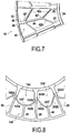
Fig. 4A is a partial perspective view of a filter comprising two filter elements stacked one on the other; -
Fig. 4B is a partial top view ofFig. 4A ; -
Fig. 5 is a partial section view of a filter element in plane V-V ofFig. 2 ; -
Fig. 6 is a partial section view of a filter element in plane VI-VI ofFig. 2 ; -
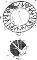
Fig. 7 is a partial perspective view of a filter element according to a second embodiment; -
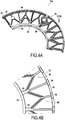
Fig. 8 is a partial perspective view of a filter element according to a third embodiment; -
Fig. 9 is a exploded perspective view of a stack of filter elements; -
Fig. 10 is a perspective view of a filter comprising a plurality of filter elements. - An embodiment of a
filter 100 comprising afilter element 10 is described with reference toFigs. 1-6 . - A
filter element 10 according to an embodiment represented inFigs. 1 and2 has aninternal face 20, anexternal face 21, afiltering mesh 22, two concentric circular edges, respectively aninner edge 24 and anouter edge 26 between which saidfiltering mesh 22 extends. The concentriccircular edges inner edge 24 mainly extends in a plane which is perpendicular to the axial direction X, i.e. a radial plane. Theouter edge 26 mainly extends in a plane which is perpendicular to the axial direction X, i.e. a radial plane. - In this embodiment, the diameter of the
outer edge 26 is about 300 mm. Of course, other diameters are possible, including, for example diameters in the range from about 100 mm to about 600 mm. - The
filter element 10 comprisesradial ribs 28 provided at least on theinternal face 20. In this embodiment, as shown inFig. 2 ,radial ribs 28 are provided on theexternal face 21 too. Thus, if threesimilar filter elements 10 are stacked, both faces of filter element in the middle of the stack face the respective internal faces of the two other filter elements, and the radial ribs provided on these respective faces interact to form compartments. - The
radial ribs 28 extend between theinner edge 24 and theouter edge 26, in the radial direction. Theradial ribs 28 are regularly distributed circumferentially in order to form sectors on saidinternal face 20, as shown inFig. 1 . In this embodiment, furtherradial ribs 28 are regularly distributed circumferentially in order to form sectors on saidexternal face 21, as shown inFig. 2 . Theradial ribs 28 on theinternal face 20 and on theexternal face 21 face one another on opposite sides of thefiltering mesh 22. In other words, theradial ribs 28 on theinternal face 20 and on theexternal face 21 are in axial correspondence with one another. - The
inner edge 24 haspassages 30 respectively communicating with corresponding ones of the sectors. Thepassages 30 are provided as notches or cutouts in theinner edge 24. Thepassages 30 are provided between consecutiveradial ribs 28. Thepassages 30 are provided on theinternal face 20. - As shown in
Fig. 2 , theouter edge 26 haspassages 32 respectively communicating with corresponding ones of the sectors. Thepassages 32 are provided as notches or cutouts in theouter edge 26. Thepassages 32 are provided between consecutiveradial ribs 28. Thepassages 32 are provided on theexternal face 20. -
Holes 34 for passing assembly rods, typically threaded rods, are defined in the vicinity of theouter edge 26 of each filter element, and they are formed by molding the same material that defines thecircular edges radial ribs 28. Male andfemale bushings 36 are arranged around theseholes 34, e.g. in aradial rib 28, for indexing twofilter elements 10 relative to each other. - In the non-limiting example shown, each
filter element 10 is divided into sixteen sectors and has fourholes 34 with bushings regularly spaced apart circumferentially. Depending in particular on its diametrical size, the filter element can have less or more sectors. For example, a filter element having an outer diameter of 100 to 150 mm may have 8 to 12 sectors, and a filter element having an outer diameter of 500 to 600 mm may have 20 to 24 sectors. - The
filter elements 10 may be manufactured by molding around thefiltering mesh 22. In other words, they may be manufactured by injection molding or similar, wherein the filtering mesh forms an insert in the mold. The molded portions may be made of metal (e.g. an aluminum alloy) or of plastics material, especially polymers. Theradial ribs 28 and the inner andouter edges filter elements 10. - For instance, liquid to be filtered, e.g. oil or water, can enter the
filter 100 through apassage 30 of theinner edge 24 of afilter element 10, cross thefiltering mesh 22 to pass from theinternal face 20 to theexternal face 21, whereby the liquid is filtered, and flow out of thefilter element 10 through apassage 32 of theouter edge 26. The opposite flow direction is possible as well. - As previously mentioned, each one of the sectors is provided with at least one reinforcing
rib 40 connecting aradial rib 28 to theouter edge 26. Said reinforcingrib 40 has a portion that is inclined, when viewed in the radial plane in which theouter edge 26 extends, with respect to theradial rib 28 and to theouter edge 26. - In this embodiment, the reinforcing
rib 40 has first and secondinclined portions radial portion 44. The first and secondinclined portions radial ribs 28 defining the sector, and to theradial portion 44. Theradial portion 44 is connected to theouter edge 26. Theradial portion 44 extends in the radial direction. - In the following, only the first
inclined portion 42a will be described. Unless specified otherwise, the secondinclined portion 42b may have all or part of the features of the firstinclined portion 42a. In this embodiment, the first and secondinclined portions radial portion 44 to which they are connected. Alternatively, the first and second inclined portions may be asymmetrical about such radial portion. - As shown in
Fig. 2 , reinforcingribs 40 are also provided on theexternal face 21. The reinforcingribs 40 on theinternal face 20 and on theexternal face 21 face one another on opposite sides of thefiltering mesh 22 so as to decrease pressure losses. Features detailed hereafter as to the firstinclined portion 42a on theinternal face 20 may apply to the inclined portions on theexternal face 21. - The first
inclined portion 42a is rectilinear but it could also be curved, provided that it includes a portion that is inclined, when viewed in the plane in which theouter edge 26 extends, with respect to theradial rib 28 and to theouter edge 26. - As illustrated in
Figs. 1 and2 , a distance D between theradial rib 28 and the firstinclined portion 42a of the reinforcingrib 40, measured in the circumferential direction, increases towards theouter edge 26. The firstinclined portion 42a and theradial rib 28 to which it is connected form an acute angle which opens towards theouter edge 26. - In this embodiment, the
radial portion 44 of the reinforcingrib 40 is rectilinear. Note that, even though a rectilinear radial portion is preferred, other alternatives are also possible. Theradial portion 44 and the firstinclined portion 42a are connected so as to form an obtuse angle. - When viewed in the plane in which the outer edge extends, the inclined portion and the radial rib form an angle from 5° to 85°. In the present embodiment, the angle is about 30°.
- The first and second
inclined portions portion 42 connecting the two consecutiveradial ribs 28 between which the sector is formed. Actually, the first and secondinclined portions portion 42, each branch being connected to aradial rib 28 at a connection zone (respectively 42a' and 42b') and the two branches joining up at the joining zone 42' where they are also connected to theradial portion 44. In this embodiment, said connectingportion 42 has the general shape of a V. - Considering the
radial portion 44 of the reinforcingrib 40, in this embodiment, the reinforcing rib has the general form of a Y. The two inclined branches of the Y are formed by the first and secondinclined portions portion 42. - The branches of the V or the Y open towards the
inner edge 24, that is, in most cases, in the direction from which the flow of fluid comes to the sector. In fact, theconnection zones 42a' and 42b' are radially closer to theinner edge 24 than the joining zone 42'. - The connecting portion formed by the first and second inclined portions may have a shape other than a V, for example a U shape. This is shown in
Fig. 8 , in which the filter element may have one or more connectingportions 142, having first and secondinclined portions respective connection zones 142a' and 142b'. This figure also shows the filter element having first and secondinclined portions connection zones 242a' and 242b', but having curved parts close to their joining zone 242'. In both cases, the connecting portion has a concave shape, of which the concavity is turned towards the inner edge, from which the flow of fluid normally comes. - As illustrated in
Fig. 2 , theradial portion 44 of the reinforcingrib 40 is connected to theouter edge 26 next to one of thepassages 32 in the circumferential direction. In this embodiment, each sector comprises twopassages 32 in theouter edge 26. Theradial portion 44 may be connected to theouter edge 26 between said twopassages 32. However, each sector may comprise only onepassage 32 in theouter edge 26, or more than twopassages 32. - The reinforcing
rib 40 may comprise anenlarged portion 46, e.g. at the intersection of theradial portion 44 and the first and secondinclined portions enlarged portion 46 may be used for labeling purposes. - As shown in
Figs. 1 and2 , the reinforcingrib 40 divides the filtering mesh surface of the sector in substantially equal areas. -
Figure 3 shows a detail ofFig. 1 . Although the reinforcing ribs may for some embodiments be connected to the radial ribs at similar radial locations, i.e. at a similar distance from the axial center of the filter element, in the embodiment shown inFig. 3 , the reinforcingribs 40 extending on either sides of one of theradial ribs 28 are connected to said oneradial rib 28 at different locations in the radial direction. More specifically,Fig. 3 shows aradial rib 28 compartmenting two adjacent sectors on theinternal face 20. A firstinclined portion 42a of one of the sectors and a secondinclined portion 42b of the other one of the sectors are connected to theradial rib 28. The firstinclined portion 42a and the secondinclined portion 42b are connected to theradial rib 28 at different locations in the radial direction. Here, aconnection zone 42a' between the firstinclined portion 42a and theradial rib 28 is closer to theouter edge 26 and farther from theinner edge 24 than aconnection zone 42b' between the secondinclined portion 42b and theradial rib 28. This facilitates the injection molding of thefilter element 10, enhances its mechanical strength and provides advantages regarding fluid flow, which will be detailed hereafter with reference toFigs. 4A and 4B . - As illustrated in
Figs. 4A and 4B , thefilter elements 10 are configured to be assembled against each other so that their respectiveinternal faces 20 face each other so as to define a space between them. Said space is circumferentially compartmented by the contactingradial ribs 28 of said internal faces. On the other hand, theradial ribs 28 provided on theexternal face 21 do not have to contact one another. Compartmenting sectors on the side of thefiltering mesh 22 on which non-filtered liquid is introduced enables de-clogging thefiltering mesh 22 by backwashing, as is known per se in the art. - A
filter 100 is made by assembling together at least twofilter elements 10, as shown inFig. 4A . To obtain a filter of desired filter capacity, it suffices to stack and assemble together a desired number ofindividual filters 100 like the filter shown inFig. 4A . - As detailed previously with reference to
Fig. 3 , the reinforcingribs 40 extending on either sides of one of theradial ribs 28 are connected to said oneradial rib 28 at different locations in the radial direction. Thanks to this feature, when twofilter elements 10 are assembled against each other so that their respectiveinternal faces 20 face each other, the reinforcingribs 40 of therespective filter elements 10 do not entirely face each other in the axial direction. That is, when twofilter elements 10 are assembled against each other so that their respectiveinternal faces 20 face each other, the reinforcingribs 40 of facing sectors of therespective filter elements 10 are shifted with respect to each other in a radial plane. This shift is particularly visible inFig. 4B . Thus, the reinforcing ribs of the adjacent filter elements may have at least parts which do not overlap axially, which facilitates the flow of fluid. - In addition, every second sector, the radial length of the
radial portion 44 of a reinforcingrib 40 may be longer than the radial length of theradial portion 44 of the reinforcingrib 40 of the adjacent sector (see e.g.Fig. 1 ). Thus, when twofilter elements 10 are assembled against each other so that their respectiveinternal faces 20 face each other, a shorterradial portion 44 axially faces a longerradial portion 44. - Those features facilitate the flow of the liquid to be filtered and decrease pressure losses.
- More generally, the reinforcing
ribs 40 help thefiltering mesh 22 withstand the pressure of the fluid to be filtered. An optimal arrangement of the reinforcingribs 40 enables to increase the fluid flow through the filter. The reinforcingribs 40 contribute to stiffening thefilter element 10. -
Figure 5 is a partial section view of thefilter element 10 in plane V-V ofFig. 2 , i.e. through aradial rib 28 of thefilter element 10. Theinternal face 20 and theexternal face 21 are separated by thefiltering mesh 22. As can be seen inFig. 5 , the thickness of theradial rib 28, in the axial direction, is constant on theexternal face 21. The thickness of theradial rib 28, in the axial direction, decreases from theinner edge 24 to theouter edge 26, on theexternal face 21. Thus, whenseveral filter elements 10 are assembled with one another as previously described, adjacent sectors communicate with each other on the external face side, while they are compartmented with each other on the internal face side. - The
inner edge 24 and theouter edge 26 are axially limited by two parallel radial planes. - As shown in
Fig. 5 , thefiltering mesh 22 has a conical shape, or frustoconical shape, about the axial direction X of thefilter element 10. An advantage thereof will be explained with reference toFig. 6 , which is a partial section view of thefilter element 10 in plane VI-VI ofFig. 2 , i.e. through apassage 30 of theinner edge 24 and apassage 32 of theouter edge 26. - As shown in
Fig. 3 , on theinternal face 20, a thickness of the reinforcingrib 40, measured in the axial direction, is less than a thickness of theradial rib 28. The thickness of theconnection zones 42a', 42b' of the first and secondinclined portions radial rib 28. Besides theconnection zone 42a' (resp. 42b'), the thickness of the firstinclined portion 42a (resp. secondinclined portion 42b) is constant. - On the other hand,
Fig. 6 shows that on theexternal face 21, a thickness of the reinforcing rib 40 (from which only the firstinclined portion 42a is illustrated inFig. 6 ), measured in the axial direction, is equal to a thickness of theradial rib 28. - In
Fig. 6 , reference sign EI stands for the axial thickness of theinner edge 24 at apassage 30, reference sign EO stands for the axial thickness of theouter edge 26 at apassage 32, reference sign PI stands for the axial distance between the end portion of thefiltering mesh 22 which is the closest to the central axis X and the closest edge of thepassage 30 of theinner edge 24, and reference sign PO stands for the axial distance between the end portion of thefiltering mesh 22 which is the farthest from the central axis X and the closest edge of thepassage 32 of theouter edge 26. - Since the
filtering mesh 22 has a conical shape, the respective distances PI and PO between thefiltering mesh 22 and thepassages filtering mesh 22 is better held by the inner andouter edges passages filter element 10 to process greater flow rates. - In the present embodiment, the
filtering mesh 22 is inserted in theinner edge 24 at a location situated between 40% and 60% of the axial thickness EI of theinner edge 24 at apassage 30. In other words, the ratio PI/EI is between 40% and 60%. - Likewise, the
filtering mesh 22 is inserted in theouter edge 26 at a location situated between 40% and 60% of the axial thickness EO of theouter edge 26 at apassage 32. In other words, the ratio PO/EO is between 40% and 60%. - Since the
filtering mesh 22 is tightly held by the inner andouter edges radial ribs 28 and the reinforcingribs 40 thinner than in prior art filter elements, and not to connect a reinforcingrib 40 to theinner edge 24. In addition, the proposed arrangement of the reinforcingribs 40 including aninclined portion filtering mesh 22 which is not available for filtering. Thus, in thefilter 100 according to the embodiment, the ratio of the filtering mesh surface available for filtering to the total filtering mesh surface is at least 75%. - Another embodiment of a
filter element 10 will now be presented with reference toFig. 7 . In this figure, the elements corresponding to or identical with those of the first embodiment will receive the same reference sign and will not be described again. The reinforcingrib 40 comprises two firstinclined portions 42a, two secondinclined portions 42b and tworadial portions 44. One firstinclined portion 42a and one secondinclined portion 42b are connected to oneradial portion 44 as previously described, e.g. in the general form of a Y. Another firstinclined portion 42a and another secondinclined portion 42b are connected to form of a Y. The tworadial portions 44 are connected to each other so as to be aligned in the radial direction. In other words, the reinforcing rib comprises two connecting portions, each having two branches respectively formed by the first and the secondinclined portions radial portions 44 respectively extending from the outer edge to the joining zone 42' of the branches of the radially outer connecting portion, and from said joining zone and the joining zone of the branches of the radially inner connecting portion. Accordingly, the reinforcingrib 40 substantially has the general shape of two Ys one above the other, or the general shape of a fishbone. - The two first
inclined portions 42a do not have the same inclination angle with respect to theouter edge 26 and to theradial ribs 28. Their respective inclinations are determined such that the reinforcingrib 40 divides the filtering mesh surface of the sector in substantially equal areas. -
Figure 9 illustrates astack 102 comprising a plurality of filter elements stacked along an axis X.Filter elements 10 are assembled in pairs with respective identical, similar orcomplementary filter elements 10, as previously described. In each pair, filterelements 10 are arranged one against the other, so that their respectiveinternal faces 20 face each other and the contactingradial ribs 28 of said respectiveinternal faces 20 partition the space between said internal faces 20. -
Assembly rods 104 are inserted in theholes 34 of thefilter elements 10, thereby ensuring alignment and axial correspondence of thefilter elements 10. - A
filter 100 is shown in perspective inFig. 10 . Thefilter 100 comprises acarter 110 and astack 102 of filter elements is arranged within thecarter 110. Thus, thefilter 100 comprises a plurality offilter elements 10, said filter elements being stacked along the axis X. - The
filter 100 comprises twoinlet portions 112 and twooutlet portions 114. Thefilter 100 may comprise one ormore inlet portions 112, and/or one ormore outlet portions 114. In this embodiment, theinlet portions 112 are fluidly connected to thepassages 30 of theinner edges 24 of thefilter elements 10, while theoutlet portions 114 are fluidly connected to thepassages 32 of the outer edges 26. However, the flow direction within thecarter 110 and thestack 102 may be reversed. - The
stack 102 of filter elements is fastened to thecarter 110 in a conventional manner. - Although the present invention has been described by referring to specific exemplary embodiments, modifications may be provided to these examples without the departing from the general scope of the invention as defined by the claims. In particular, individual characteristics of the different illustrated/mentioned embodiments may be combined in additional embodiments. Therefore, the description and the drawings should be considered in an illustrative rather than in a restrictive sense.
Claims (19)
- A filter element (10), having an internal face (20), an external face (21), a filtering mesh (22), two concentric circular edges, respectively an inner edge (24) and an outer edge (26) between which said filtering mesh (22) extends, and radial ribs (28) provided at least on the internal face (20), said radial ribs (28) extending between said concentric edges (24, 26) and being distributed circumferentially in order to form sectors on said internal face (20), said filter element (10) being configured to be assembled against a corresponding filter element so that said internal face (20) faces said corresponding filter element and said radial ribs (28) delimiting the sectors act to circumferentially form compartments in a space between said internal face and said corresponding filter element, said inner edge (24) having passages (30) respectively communicating with corresponding ones of the sectors, characterized in that at least some of the sectors, preferably most of the sectors or even all of the sectors are each provided with at least one reinforcing rib (40) connecting a radial rib (28) to the outer edge (26), and in that said reinforcing rib (40) has an inclined portion (42a, 42b) that, when viewed in a radial plane, forms a non-zero angle with respect to the radial rib (28) and with respect to the outer edge (26).
- The filter element as claimed in claim 1, wherein a distance (D) between the radial rib (28) and the inclined portion (42a, 42b) of the reinforcing rib (40), measured in the circumferential direction, increases towards the outer edge (26).
- The filter element as claimed in claim 1 or 2, wherein when viewed in the radial plane in which the outer edge (26) extends, the inclined portion (42a, 42b) and the radial rib (28) form an angle greater than 5°, preferably greater than 10°, preferably greater than 15°, and less than 85°, preferably less than 70°, preferably less than 60°.
- The filter element as claimed in any one of claims 1 to 3, wherein the reinforcing rib (40) comprises a connecting portion (42) connecting the two consecutive radial ribs (28) delimiting the sector in which said reinforcing rib is formed, said connecting portion (42) having two branches (42a, 42b), each connected to one of said two consecutive radial ribs (28) at a connection zone (42a', 42b'), said branches joining up at a joining zone (42').
- The filter element as claimed in claim 4, wherein the connection zones (42a', 42b') are radially closer to the inner edge than the joining zone (42').
- The filter element as claimed in claim 4 or 5, wherein the connecting portion (42) has the general shape of a V or a U.
- The filter element as claimed in any one of claims 1 to 6, wherein the reinforcing rib (40) has the general shape of a Y.
- The filter element as claimed in any one of claims 4 to 6, wherein the reinforcing rib (40) comprises a first and a second connecting portion (42), each having two branches (42a, 42b), each connected to one of said two consecutive radial ribs (28), and two radial portions (44), the first radial portion extending between the outer edge and the joining zone (42') of the branches of the first connecting portions, and the second radial portion extending between said joining zone of the branches of the first connecting portion and the joining zone (42') of the branches of the second connecting portion.
- The filter element as claimed in any one of claims 1 to 8, wherein the reinforcing rib (40) is connected to the outer edge (26) next to a fluid passage (32) thereof in the circumferential direction.
- The filter element as claimed in any one of claims 1 to 9, wherein the reinforcing ribs (40) extending on either sides of one of the radial ribs (28) are connected to said one radial rib at different locations (42a', 42b') in the radial direction.
- The filter element as claimed in any one of claims 1 to 10, wherein the filtering mesh (22) has a conical shape.
- The filter element as claimed in any one of claims 1 to 11, wherein the filtering mesh (22) is secured to the inner edge (24) at a location (PI) situated between 40% and 60% of the axial thickness (EI) of the inner edge (24) at a passage (30).
- The filter element as claimed in any one of claims 1 to 12, wherein said reinforcing rib (40) divides the filtering mesh surface of the sector in areas of substantially similar size.
- The filter element as claimed in any one of claims 1 to 13 wherein the ratio of the filtering mesh surface available for filtering to the total filtering mesh surface is at least 70%, preferably at least 75%.
- The filter element as claimed in any one of claims 1 to 14, wherein radial ribs (28) are further provided on the external face (21), said radial ribs extending between said two concentric circular edges (24, 26) and being regularly distributed circumferentially in order to form sectors on said external face (21), and wherein the radial ribs (28) on the internal face (20) are in axial correspondence with the radial ribs on the external face (21).
- The filter element as claimed in any one of claims 1 to 15, wherein the radial ribs (28) and/or the reinforcing rib (40) are made of polymer.
- The filter element as claimed in any one of claims 1 to 16, wherein the filtering mesh (22) is free of supporting mesh.
- A pair of filter elements as claimed in any one of claims 1 to 17, arranged one against the other, so that their respective internal faces face each other and the contacting radial ribs (28) of said respective internal faces partition the space between said internal faces.
- A filter (100) comprising a plurality of filter elements as claimed in any one of claims 1 to 18, said filter elements being stacked along an axis (X).
Priority Applications (10)
| Application Number | Priority Date | Filing Date | Title |
|---|---|---|---|
| EP16305082.6A EP3199219B1 (en) | 2016-01-28 | 2016-01-28 | Filter element and filter comprising at least two filter elements |
| PL16305082T PL3199219T3 (en) | 2016-01-28 | 2016-01-28 | Filter element and filter comprising at least two filter elements |
| ES16305082.6T ES2688446T3 (en) | 2016-01-28 | 2016-01-28 | Filter and filter element comprising at least two filter elements |
| DK16305082.6T DK3199219T3 (en) | 2016-01-28 | 2016-01-28 | FILTER ELEMENTS AND FILTERS CONTAINING AT LEAST TWO FILTER ELEMENTS |
| RU2018130846A RU2686911C1 (en) | 2016-01-28 | 2017-01-26 | Filter element and filter comprising at least two filter elements |
| US16/061,629 US10960327B2 (en) | 2016-01-28 | 2017-01-26 | Filter element and filter comprising at least two filter elements |
| CN201780008927.1A CN108601995B (en) | 2016-01-28 | 2017-01-26 | Filter element and filter comprising at least two filter elements |
| PCT/EP2017/051685 WO2017129701A1 (en) | 2016-01-28 | 2017-01-26 | Filter element and filter comprising at least two filter elements |
| KR1020187024363A KR102176915B1 (en) | 2016-01-28 | 2017-01-26 | A filter element and a filter containing two or more filter elements |
| JP2018558486A JP6700428B2 (en) | 2016-01-28 | 2017-01-26 | Filter element and filter comprising at least two filter elements |
Applications Claiming Priority (1)
| Application Number | Priority Date | Filing Date | Title |
|---|---|---|---|
| EP16305082.6A EP3199219B1 (en) | 2016-01-28 | 2016-01-28 | Filter element and filter comprising at least two filter elements |
Publications (2)
| Publication Number | Publication Date |
|---|---|
| EP3199219A1 EP3199219A1 (en) | 2017-08-02 |
| EP3199219B1 true EP3199219B1 (en) | 2018-08-08 |
Family
ID=55451144
Family Applications (1)
| Application Number | Title | Priority Date | Filing Date |
|---|---|---|---|
| EP16305082.6A Active EP3199219B1 (en) | 2016-01-28 | 2016-01-28 | Filter element and filter comprising at least two filter elements |
Country Status (10)
| Country | Link |
|---|---|
| US (1) | US10960327B2 (en) |
| EP (1) | EP3199219B1 (en) |
| JP (1) | JP6700428B2 (en) |
| KR (1) | KR102176915B1 (en) |
| CN (1) | CN108601995B (en) |
| DK (1) | DK3199219T3 (en) |
| ES (1) | ES2688446T3 (en) |
| PL (1) | PL3199219T3 (en) |
| RU (1) | RU2686911C1 (en) |
| WO (1) | WO2017129701A1 (en) |
Families Citing this family (5)
| Publication number | Priority date | Publication date | Assignee | Title |
|---|---|---|---|---|
| DK3254743T3 (en) | 2016-06-10 | 2019-05-20 | Alfa Laval Corp Ab | FILTRATION UNIT WITH AUTOMATIC RETURN |
| CN111770782B (en) * | 2017-11-29 | 2023-06-16 | 马干Aca过滤公司 | Filtration system |
| EP3753622B1 (en) * | 2019-06-17 | 2022-04-13 | Gerum GmbH | Filter unit and filtration assembly |
| PL3782711T3 (en) * | 2019-08-19 | 2022-06-20 | Alfa Laval Moatti | Filtering unit with improved cover assembly |
| EP4268924A1 (en) | 2022-04-26 | 2023-11-01 | Alfa Laval Moatti | Filter element and filter comprising at least two filter elements |
Family Cites Families (17)
| Publication number | Priority date | Publication date | Assignee | Title |
|---|---|---|---|---|
| US1812725A (en) * | 1927-08-27 | 1931-06-30 | Oliver United Filters Inc | Method of attaching filter cloth |
| US2088199A (en) | 1936-02-01 | 1937-07-27 | Stanley F Gleason | Filter |
| GB512972A (en) | 1937-03-27 | 1939-09-29 | Ig Farbenindustrie Ag | Improvements in filters |
| US2592527A (en) | 1945-12-07 | 1952-04-15 | Us Hoffman Machinery Corp | Filter |
| US2592849A (en) | 1948-05-12 | 1952-04-15 | Wipac Filtration Ltd | Filter |
| CH306628A (en) | 1951-09-29 | 1955-04-30 | Gmbh Robert Bosch | Filters, in particular for liquid fuels. |
| BE516316A (en) | 1952-02-23 | 1900-01-01 | ||
| US3079001A (en) | 1958-10-08 | 1963-02-26 | May Griffith | Mechanical filter assembly |
| CH386989A (en) * | 1962-12-12 | 1965-01-31 | Brasco Sa | Filtered |
| JPS479395Y1 (en) * | 1969-02-22 | 1972-04-10 | ||
| JPS4732221Y1 (en) * | 1969-05-07 | 1972-09-28 | ||
| JPS479395U (en) | 1971-02-25 | 1972-10-04 | ||
| JPS4732221U (en) | 1971-04-23 | 1972-12-11 | ||
| IL74873A (en) * | 1985-04-10 | 1990-07-12 | Drori Mordeki | Multiple disc type filter and disc construction useful therein |
| FR2779359B1 (en) * | 1998-06-05 | 2000-08-25 | Alfa Laval Moatti Snc | FILTER ELEMENT FOR USE IN A FILTRATION DEVICE |
| RU2166351C1 (en) * | 2000-03-29 | 2001-05-10 | Тимонин Александр Семенович | Disk filter |
| FR2964329B1 (en) * | 2010-09-03 | 2012-09-28 | Alfa Laval Moatti | AUTOMATIC CLEANING FILTER |
-
2016
- 2016-01-28 PL PL16305082T patent/PL3199219T3/en unknown
- 2016-01-28 DK DK16305082.6T patent/DK3199219T3/en active
- 2016-01-28 EP EP16305082.6A patent/EP3199219B1/en active Active
- 2016-01-28 ES ES16305082.6T patent/ES2688446T3/en active Active
-
2017
- 2017-01-26 US US16/061,629 patent/US10960327B2/en active Active
- 2017-01-26 CN CN201780008927.1A patent/CN108601995B/en active Active
- 2017-01-26 WO PCT/EP2017/051685 patent/WO2017129701A1/en active Application Filing
- 2017-01-26 RU RU2018130846A patent/RU2686911C1/en active
- 2017-01-26 KR KR1020187024363A patent/KR102176915B1/en active IP Right Grant
- 2017-01-26 JP JP2018558486A patent/JP6700428B2/en active Active
Non-Patent Citations (1)
| Title |
|---|
| None * |
Also Published As
| Publication number | Publication date |
|---|---|
| US20180369722A1 (en) | 2018-12-27 |
| JP6700428B2 (en) | 2020-05-27 |
| JP2019507012A (en) | 2019-03-14 |
| CN108601995A (en) | 2018-09-28 |
| EP3199219A1 (en) | 2017-08-02 |
| PL3199219T3 (en) | 2019-01-31 |
| WO2017129701A1 (en) | 2017-08-03 |
| CN108601995B (en) | 2021-03-12 |
| RU2686911C1 (en) | 2019-05-06 |
| ES2688446T3 (en) | 2018-11-02 |
| DK3199219T3 (en) | 2018-12-03 |
| KR20180101592A (en) | 2018-09-12 |
| US10960327B2 (en) | 2021-03-30 |
| KR102176915B1 (en) | 2020-11-10 |
Similar Documents
| Publication | Publication Date | Title |
|---|---|---|
| US10960327B2 (en) | Filter element and filter comprising at least two filter elements | |
| US4880537A (en) | Multiple disc type filter and disc construction useful therein | |
| EP0674931B1 (en) | Hub ring and supporting plate for a filter and methods for manufacturing these members | |
| US4683060A (en) | Multiple-disc type filters | |
| US20060243653A1 (en) | Dialysis filter | |
| JP6267244B2 (en) | Filtration support geometry and membrane | |
| CN106039877A (en) | Filter holding deice and filter arrangement structure | |
| US20130008848A1 (en) | Filter comprising stackable filter wafers with filtering channels on opposing sides of the wafers | |
| US20080296217A1 (en) | Porous Monolithic Support for a Filtering Element | |
| RU2585782C2 (en) | Novel geometry of filter elements | |
| US20100032364A1 (en) | Disc filter sector and disc filter | |
| CN101983311B (en) | A plate heat exchanger | |
| CN1330400C (en) | Filter cartridge | |
| EP4268924A1 (en) | Filter element and filter comprising at least two filter elements | |
| CN102003245A (en) | Engine oil filter | |
| US11213769B2 (en) | Nozzles/screens used in the fluid processing units | |
| KR100323574B1 (en) | Disc Filter Elements and Disc Filter Systems | |
| CN112710172B (en) | Central body in spiral heat exchanger | |
| US20230092417A1 (en) | Heat exchanger core and heat exchanger | |
| CN101057062A (en) | Steam turbine comprising two steam chambers | |
| JP2021165000A (en) | Polymer filter | |
| KR101356123B1 (en) | high differential pressure control Valve for marine plant | |
| WO2015004157A1 (en) | Riser for a filter unit for highly viscous fluids, and filter unit |
Legal Events
| Date | Code | Title | Description |
|---|---|---|---|
| PUAI | Public reference made under article 153(3) epc to a published international application that has entered the european phase |
Free format text: ORIGINAL CODE: 0009012 |
|
| STAA | Information on the status of an ep patent application or granted ep patent |
Free format text: STATUS: THE APPLICATION HAS BEEN PUBLISHED |
|
| AK | Designated contracting states |
Kind code of ref document: A1 Designated state(s): AL AT BE BG CH CY CZ DE DK EE ES FI FR GB GR HR HU IE IS IT LI LT LU LV MC MK MT NL NO PL PT RO RS SE SI SK SM TR |
|
| AX | Request for extension of the european patent |
Extension state: BA ME |
|
| STAA | Information on the status of an ep patent application or granted ep patent |
Free format text: STATUS: REQUEST FOR EXAMINATION WAS MADE |
|
| 17P | Request for examination filed |
Effective date: 20171005 |
|
| RBV | Designated contracting states (corrected) |
Designated state(s): AL AT BE BG CH CY CZ DE DK EE ES FI FR GB GR HR HU IE IS IT LI LT LU LV MC MK MT NL NO PL PT RO RS SE SI SK SM TR |
|
| GRAP | Despatch of communication of intention to grant a patent |
Free format text: ORIGINAL CODE: EPIDOSNIGR1 |
|
| STAA | Information on the status of an ep patent application or granted ep patent |
Free format text: STATUS: GRANT OF PATENT IS INTENDED |
|
| INTG | Intention to grant announced |
Effective date: 20180301 |
|
| RAP1 | Party data changed (applicant data changed or rights of an application transferred) |
Owner name: ALVA LAVAL MOATTI SAS Owner name: ALFA LAVAL CORPORATE AB |
|
| RAP1 | Party data changed (applicant data changed or rights of an application transferred) |
Owner name: ALFA LAVAL CORPORATE AB Owner name: ALFA LAVAL MOATTI SAS |
|
| GRAS | Grant fee paid |
Free format text: ORIGINAL CODE: EPIDOSNIGR3 |
|
| GRAJ | Information related to disapproval of communication of intention to grant by the applicant or resumption of examination proceedings by the epo deleted |
Free format text: ORIGINAL CODE: EPIDOSDIGR1 |
|
| GRAL | Information related to payment of fee for publishing/printing deleted |
Free format text: ORIGINAL CODE: EPIDOSDIGR3 |
|
| STAA | Information on the status of an ep patent application or granted ep patent |
Free format text: STATUS: REQUEST FOR EXAMINATION WAS MADE |
|
| GRAR | Information related to intention to grant a patent recorded |
Free format text: ORIGINAL CODE: EPIDOSNIGR71 |
|
| STAA | Information on the status of an ep patent application or granted ep patent |
Free format text: STATUS: GRANT OF PATENT IS INTENDED |
|
| INTC | Intention to grant announced (deleted) | ||
| INTG | Intention to grant announced |
Effective date: 20180522 |
|
| GRAA | (expected) grant |
Free format text: ORIGINAL CODE: 0009210 |
|
| STAA | Information on the status of an ep patent application or granted ep patent |
Free format text: STATUS: THE PATENT HAS BEEN GRANTED |
|
| AK | Designated contracting states |
Kind code of ref document: B1 Designated state(s): AL AT BE BG CH CY CZ DE DK EE ES FI FR GB GR HR HU IE IS IT LI LT LU LV MC MK MT NL NO PL PT RO RS SE SI SK SM TR |
|
| REG | Reference to a national code |
Ref country code: GB Ref legal event code: FG4D |
|
| REG | Reference to a national code |
Ref country code: CH Ref legal event code: EP Ref country code: AT Ref legal event code: REF Ref document number: 1026341 Country of ref document: AT Kind code of ref document: T Effective date: 20180815 |
|
| REG | Reference to a national code |
Ref country code: IE Ref legal event code: FG4D |
|
| REG | Reference to a national code |
Ref country code: DE Ref legal event code: R096 Ref document number: 602016004608 Country of ref document: DE |
|
| REG | Reference to a national code |
Ref country code: SE Ref legal event code: TRGR |
|
| REG | Reference to a national code |
Ref country code: ES Ref legal event code: FG2A Ref document number: 2688446 Country of ref document: ES Kind code of ref document: T3 Effective date: 20181102 |
|
| REG | Reference to a national code |
Ref country code: NL Ref legal event code: FP |
|
| REG | Reference to a national code |
Ref country code: DK Ref legal event code: T3 Effective date: 20181128 |
|
| REG | Reference to a national code |
Ref country code: LT Ref legal event code: MG4D |
|
| PG25 | Lapsed in a contracting state [announced via postgrant information from national office to epo] |
Ref country code: LT Free format text: LAPSE BECAUSE OF FAILURE TO SUBMIT A TRANSLATION OF THE DESCRIPTION OR TO PAY THE FEE WITHIN THE PRESCRIBED TIME-LIMIT Effective date: 20180808 Ref country code: RS Free format text: LAPSE BECAUSE OF FAILURE TO SUBMIT A TRANSLATION OF THE DESCRIPTION OR TO PAY THE FEE WITHIN THE PRESCRIBED TIME-LIMIT Effective date: 20180808 Ref country code: IS Free format text: LAPSE BECAUSE OF FAILURE TO SUBMIT A TRANSLATION OF THE DESCRIPTION OR TO PAY THE FEE WITHIN THE PRESCRIBED TIME-LIMIT Effective date: 20181208 Ref country code: NO Free format text: LAPSE BECAUSE OF FAILURE TO SUBMIT A TRANSLATION OF THE DESCRIPTION OR TO PAY THE FEE WITHIN THE PRESCRIBED TIME-LIMIT Effective date: 20181108 |
|
| PG25 | Lapsed in a contracting state [announced via postgrant information from national office to epo] |
Ref country code: LV Free format text: LAPSE BECAUSE OF FAILURE TO SUBMIT A TRANSLATION OF THE DESCRIPTION OR TO PAY THE FEE WITHIN THE PRESCRIBED TIME-LIMIT Effective date: 20180808 Ref country code: HR Free format text: LAPSE BECAUSE OF FAILURE TO SUBMIT A TRANSLATION OF THE DESCRIPTION OR TO PAY THE FEE WITHIN THE PRESCRIBED TIME-LIMIT Effective date: 20180808 Ref country code: AL Free format text: LAPSE BECAUSE OF FAILURE TO SUBMIT A TRANSLATION OF THE DESCRIPTION OR TO PAY THE FEE WITHIN THE PRESCRIBED TIME-LIMIT Effective date: 20180808 |
|
| REG | Reference to a national code |
Ref country code: GR Ref legal event code: EP Ref document number: 20180402828 Country of ref document: GR Effective date: 20190225 |
|
| PG25 | Lapsed in a contracting state [announced via postgrant information from national office to epo] |
Ref country code: CZ Free format text: LAPSE BECAUSE OF FAILURE TO SUBMIT A TRANSLATION OF THE DESCRIPTION OR TO PAY THE FEE WITHIN THE PRESCRIBED TIME-LIMIT Effective date: 20180808 Ref country code: EE Free format text: LAPSE BECAUSE OF FAILURE TO SUBMIT A TRANSLATION OF THE DESCRIPTION OR TO PAY THE FEE WITHIN THE PRESCRIBED TIME-LIMIT Effective date: 20180808 Ref country code: RO Free format text: LAPSE BECAUSE OF FAILURE TO SUBMIT A TRANSLATION OF THE DESCRIPTION OR TO PAY THE FEE WITHIN THE PRESCRIBED TIME-LIMIT Effective date: 20180808 |
|
| REG | Reference to a national code |
Ref country code: DE Ref legal event code: R097 Ref document number: 602016004608 Country of ref document: DE |
|
| PG25 | Lapsed in a contracting state [announced via postgrant information from national office to epo] |
Ref country code: SK Free format text: LAPSE BECAUSE OF FAILURE TO SUBMIT A TRANSLATION OF THE DESCRIPTION OR TO PAY THE FEE WITHIN THE PRESCRIBED TIME-LIMIT Effective date: 20180808 Ref country code: SM Free format text: LAPSE BECAUSE OF FAILURE TO SUBMIT A TRANSLATION OF THE DESCRIPTION OR TO PAY THE FEE WITHIN THE PRESCRIBED TIME-LIMIT Effective date: 20180808 |
|
| PLBE | No opposition filed within time limit |
Free format text: ORIGINAL CODE: 0009261 |
|
| STAA | Information on the status of an ep patent application or granted ep patent |
Free format text: STATUS: NO OPPOSITION FILED WITHIN TIME LIMIT |
|
| 26N | No opposition filed |
Effective date: 20190509 |
|
| PG25 | Lapsed in a contracting state [announced via postgrant information from national office to epo] |
Ref country code: SI Free format text: LAPSE BECAUSE OF FAILURE TO SUBMIT A TRANSLATION OF THE DESCRIPTION OR TO PAY THE FEE WITHIN THE PRESCRIBED TIME-LIMIT Effective date: 20180808 Ref country code: MC Free format text: LAPSE BECAUSE OF FAILURE TO SUBMIT A TRANSLATION OF THE DESCRIPTION OR TO PAY THE FEE WITHIN THE PRESCRIBED TIME-LIMIT Effective date: 20180808 |
|
| REG | Reference to a national code |
Ref country code: CH Ref legal event code: PL |
|
| PG25 | Lapsed in a contracting state [announced via postgrant information from national office to epo] |
Ref country code: LU Free format text: LAPSE BECAUSE OF NON-PAYMENT OF DUE FEES Effective date: 20190128 |
|
| REG | Reference to a national code |
Ref country code: IE Ref legal event code: MM4A |
|
| PG25 | Lapsed in a contracting state [announced via postgrant information from national office to epo] |
Ref country code: FR Free format text: LAPSE BECAUSE OF NON-PAYMENT OF DUE FEES Effective date: 20190131 |
|
| PG25 | Lapsed in a contracting state [announced via postgrant information from national office to epo] |
Ref country code: LI Free format text: LAPSE BECAUSE OF NON-PAYMENT OF DUE FEES Effective date: 20190131 Ref country code: CH Free format text: LAPSE BECAUSE OF NON-PAYMENT OF DUE FEES Effective date: 20190131 |
|
| PG25 | Lapsed in a contracting state [announced via postgrant information from national office to epo] |
Ref country code: IE Free format text: LAPSE BECAUSE OF NON-PAYMENT OF DUE FEES Effective date: 20190128 |
|
| PG25 | Lapsed in a contracting state [announced via postgrant information from national office to epo] |
Ref country code: TR Free format text: LAPSE BECAUSE OF FAILURE TO SUBMIT A TRANSLATION OF THE DESCRIPTION OR TO PAY THE FEE WITHIN THE PRESCRIBED TIME-LIMIT Effective date: 20180808 |
|
| PG25 | Lapsed in a contracting state [announced via postgrant information from national office to epo] |
Ref country code: MT Free format text: LAPSE BECAUSE OF NON-PAYMENT OF DUE FEES Effective date: 20190128 Ref country code: PT Free format text: LAPSE BECAUSE OF FAILURE TO SUBMIT A TRANSLATION OF THE DESCRIPTION OR TO PAY THE FEE WITHIN THE PRESCRIBED TIME-LIMIT Effective date: 20181208 |
|
| REG | Reference to a national code |
Ref country code: AT Ref legal event code: UEP Ref document number: 1026341 Country of ref document: AT Kind code of ref document: T Effective date: 20180808 |
|
| PG25 | Lapsed in a contracting state [announced via postgrant information from national office to epo] |
Ref country code: CY Free format text: LAPSE BECAUSE OF FAILURE TO SUBMIT A TRANSLATION OF THE DESCRIPTION OR TO PAY THE FEE WITHIN THE PRESCRIBED TIME-LIMIT Effective date: 20180808 |
|
| PG25 | Lapsed in a contracting state [announced via postgrant information from national office to epo] |
Ref country code: HU Free format text: LAPSE BECAUSE OF FAILURE TO SUBMIT A TRANSLATION OF THE DESCRIPTION OR TO PAY THE FEE WITHIN THE PRESCRIBED TIME-LIMIT; INVALID AB INITIO Effective date: 20160128 |
|
| PG25 | Lapsed in a contracting state [announced via postgrant information from national office to epo] |
Ref country code: MK Free format text: LAPSE BECAUSE OF FAILURE TO SUBMIT A TRANSLATION OF THE DESCRIPTION OR TO PAY THE FEE WITHIN THE PRESCRIBED TIME-LIMIT Effective date: 20180808 |
|
| PGFP | Annual fee paid to national office [announced via postgrant information from national office to epo] |
Ref country code: BE Payment date: 20221216 Year of fee payment: 8 |
|
| PGFP | Annual fee paid to national office [announced via postgrant information from national office to epo] |
Ref country code: ES Payment date: 20230213 Year of fee payment: 8 Ref country code: DK Payment date: 20230111 Year of fee payment: 8 Ref country code: AT Payment date: 20221228 Year of fee payment: 8 |
|
| PGFP | Annual fee paid to national office [announced via postgrant information from national office to epo] |
Ref country code: PL Payment date: 20221130 Year of fee payment: 8 Ref country code: IT Payment date: 20221213 Year of fee payment: 8 Ref country code: DE Payment date: 20221207 Year of fee payment: 8 |
|
| P01 | Opt-out of the competence of the unified patent court (upc) registered |
Effective date: 20230324 |
|
| PGFP | Annual fee paid to national office [announced via postgrant information from national office to epo] |
Ref country code: GR Payment date: 20231213 Year of fee payment: 9 Ref country code: GB Payment date: 20231207 Year of fee payment: 9 |
|
| PGFP | Annual fee paid to national office [announced via postgrant information from national office to epo] |
Ref country code: SE Payment date: 20231213 Year of fee payment: 9 Ref country code: NL Payment date: 20231215 Year of fee payment: 9 Ref country code: FI Payment date: 20231219 Year of fee payment: 9 Ref country code: BG Payment date: 20231219 Year of fee payment: 9 |
|
| PGFP | Annual fee paid to national office [announced via postgrant information from national office to epo] |
Ref country code: PL Payment date: 20231215 Year of fee payment: 9 Ref country code: BE Payment date: 20231219 Year of fee payment: 9 |
|
| PGFP | Annual fee paid to national office [announced via postgrant information from national office to epo] |
Ref country code: ES Payment date: 20240205 Year of fee payment: 9 |