EP3199123B1 - Endodontic apical plug - Google Patents
Endodontic apical plug Download PDFInfo
- Publication number
- EP3199123B1 EP3199123B1 EP14828509.1A EP14828509A EP3199123B1 EP 3199123 B1 EP3199123 B1 EP 3199123B1 EP 14828509 A EP14828509 A EP 14828509A EP 3199123 B1 EP3199123 B1 EP 3199123B1
- Authority
- EP
- European Patent Office
- Prior art keywords
- filler
- elliptical
- canal
- root
- top end
- Prior art date
- Legal status (The legal status is an assumption and is not a legal conclusion. Google has not performed a legal analysis and makes no representation as to the accuracy of the status listed.)
- Active
Links
- 239000000945 filler Substances 0.000 claims description 75
- 239000000463 material Substances 0.000 claims description 42
- 210000004262 dental pulp cavity Anatomy 0.000 claims description 14
- 238000002347 injection Methods 0.000 claims description 9
- 239000007924 injection Substances 0.000 claims description 9
- 238000009434 installation Methods 0.000 claims 1
- 238000013461 design Methods 0.000 description 5
- 238000000034 method Methods 0.000 description 5
- 210000001519 tissue Anatomy 0.000 description 3
- 239000011248 coating agent Substances 0.000 description 2
- 238000000576 coating method Methods 0.000 description 2
- 238000010438 heat treatment Methods 0.000 description 2
- 238000003780 insertion Methods 0.000 description 2
- 230000037431 insertion Effects 0.000 description 2
- 210000005036 nerve Anatomy 0.000 description 2
- 238000000926 separation method Methods 0.000 description 2
- 230000001580 bacterial effect Effects 0.000 description 1
- 239000000560 biocompatible material Substances 0.000 description 1
- 238000001816 cooling Methods 0.000 description 1
- 238000005516 engineering process Methods 0.000 description 1
- 238000002474 experimental method Methods 0.000 description 1
- 230000008595 infiltration Effects 0.000 description 1
- 238000001764 infiltration Methods 0.000 description 1
- 239000003112 inhibitor Substances 0.000 description 1
- 238000005259 measurement Methods 0.000 description 1
- 239000012466 permeate Substances 0.000 description 1
- 239000002631 root canal filling material Substances 0.000 description 1
- 238000007789 sealing Methods 0.000 description 1
- 210000001114 tooth apex Anatomy 0.000 description 1
- 210000004746 tooth root Anatomy 0.000 description 1
Images

Classifications
-
- A—HUMAN NECESSITIES
- A61—MEDICAL OR VETERINARY SCIENCE; HYGIENE
- A61C—DENTISTRY; APPARATUS OR METHODS FOR ORAL OR DENTAL HYGIENE
- A61C5/00—Filling or capping teeth
- A61C5/50—Implements for filling root canals; Methods or instruments for medication of tooth nerve channels
-
- A—HUMAN NECESSITIES
- A61—MEDICAL OR VETERINARY SCIENCE; HYGIENE
- A61C—DENTISTRY; APPARATUS OR METHODS FOR ORAL OR DENTAL HYGIENE
- A61C5/00—Filling or capping teeth
- A61C5/50—Implements for filling root canals; Methods or instruments for medication of tooth nerve channels
- A61C5/55—Implements for filling root canals; Methods or instruments for medication of tooth nerve channels with heating means, e.g. for heating gutta percha
Definitions
- This invention is related to a tooth canal filler used for filling tooth root canals after extracting the nerve and preparing the canal for a final root filling status.
- Thermafil® a canal filling method with European patent No. EP 1001728 B1 . It requires heating the canal filler in advance prior to putting it in the canal in order to be mild. This causes an increase in tissue temperature to an extent that could harm it. Additionally, the material coating the filler may separate from it during the insertion process, which may harm the distribution of the leak-proof material inside the root canal; in addition to the problem arising from the need to remove the gripping part after the clinical procedure is performed.
- EU patent application No. EP 2015109 A1 presented another canal filler.
- the problem with this system is that the leak-proof material coating the filler cannot interpenetrate and have the complex shape of canals. Therefore, there is a possibility of bacterial infiltration into such spaces. There is also the problem of the need to remove the gripping part after the clinical procedure.
- US patent application No. US 2001/0217669 A1 presented a canal filler with no measurement scale on the filler gripping part and protrusions in the head of the filler that stop it inside the canal. Still, there exists the problem of heating the filler, the probable separation of the leak-proof material from the filler during insertion into canals, and the need to remove the gripping part after the clinical procedure is conducted.
- US 3,919,774 A1 present a canal filler shaped like a post and comprising a sealing apical end, a longitudinal cavity, and a plurality of lateral openings over the length of the filler, wherein the openings are connected to the longitudinal cavity to allow injected material to exit the longitudinal cavity to fill the tooth canal.
- KSA patent application No. 3335 also discloses a filler; however, there are several problems in the design of this filler. This includes the problem of designing the filler's cap with no supports that prevent it from going in the opposite direction, especially when the needle used in injecting the canal filling material is taken out. Additionally, there are no leak-proof means to prevent the leak in the filler cap, and designing the lateral openings in the shape of a teardrop makes the flow of canal filling material difficult, and its triangular-shaped (elliptical) top part of it is difficult to make. It being short makes the flow of canal filling material difficult as well. As for the presence of guiding wings - it being continuous, this causes two problems.
- This invention is according to claim 1.
- One of the advantages of this invention is that it does not need a gripping part like previous inventions that had the problem of their removal during filling or in case there is a need for a post inside the root to support fixed prosthodontics, because moving the gripping part and the surrounding filling harms the quality of the filling and may cause it to come out from its place. Additionally, the driller may change its direction inside the root because of the gripping part, which may cause a side hole in the canal wall.
- the design of the current filler has a place to meet with the needle used in injecting the canal filling material, which the filler depends on when transferred into the root, such as (system B®, obtura II®, obtura III®, and HotShot®), with no need for any additional complex devices.
- One unique advantage of the invention is that the filler is not heated outside the canal, which eliminates the risk of harming tissue due to high temperature. Additionally, injecting the leak-proof material is done after inserting the filler into its final position inside the root. This also eliminates the risk of separation of the leak-proof material from the filler and gives it an opportunity to better take the shape of the canal.
- the design of the filler's cap which has a double leak-proof cap, the design has two consecutive supports in the cap with an external angle of 45 degrees and an internal angle of 90 degrees that help prevent the leakage of the root filling material outside the canal. It serves as an inhibitor that fixes the carrier in its position in case the needle used in injecting the canal filling material is taken out.
- the length of the cap or filler does not exceed 5 mm from the root apex, which facilitates placing a post in the remaining space in the canal. This solves the problem of having a gripping part in the previous inventions, which obstructs this step. Additionally, there is a place allocated where the needle used in injecting the filling material meets the filler. That makes its exit easier after placing the filler in its final position and injecting the filling material. There is also a double edge at the top of the filler that further ensures preventing the leakage of material and the possibility of making solely the filler cap from the same canal filling material. This means making the filler in its entirety from one material and the cap alone from the same canal filling material. This makes the filling better take the shape of the root cap.
- the presence of a cylindrical, longitudinal cavity inside the filler facilitates repeating treatment if the endodontitis returns and there is a desire to remove it from the root canal because this cavity helps root treatment tools (dental file) to hold inside the cavity and pull the filler out.
- Figure (1 ) illustrates a longitudinal section of the filler used in filling teeth root canals (1) made of plastic (or any other biocompatible material).
- This filler (1) that measures about 5 mm is placed inside the bottom of the tooth, and the remaining space is filled with filling material known in dentistry.
- the filler (1) is unique for its elliptical end (5) that allows it to be placed in the desired place, as the elliptical end (5) sets in the tooth apex to prevent leakage of filling material to jaw bones.
- the filler (1) has lateral openings (4) close to the elliptical end (5). Each opening (4) is linked to the longitudinal cavity (3) that reaches from top of the filler (1) (the opposite end of the elliptical end (5)) to the openings (3).
- the filler (1) is linked from the outside to guiding wings (2) with consecutively discontinuous spaces that separate each wing into several protrusions, which helps the flow of the filling material into the filler (1) and better fill the place. Additionally, these consecutive distances in the wings (2) increase the flexibility of the filler and its ability to bend inside the root canal.
- Figure (2 ) illustrates a cross-section of the filler used in filling teeth root canals from above. Round angles of the of guiding wings (2) are shown, in addition to the place designated for the needle used in injecting the canal filling material (7) and the longitudinal cavity (4) extending from the top of the filler (1) to the elliptical end (5).
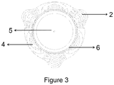
- Figure (3 ) illustrates a cross-section of the filler used in filling teeth root canal from below. It shows the elliptical end (5) of the filler that can be made of the same material as that of the filler or can be made separately of the same material of the canal filler. There also appears the role of the double leak-proof cap (6).
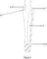
- Figure (4 ) illustrates the way the needle used in injecting the filling material meets the filler and its internal components, in which the longitudinal cavity (3) is getting narrower when approaching the top end of the openings (9), as the injection tube stops directly right in its designated place (7).
- Each one of the openings (4) has an elliptical shape, parallel in the middle. This design helps distributing the exit of filling material through the openings (4).
- the work mechanism of the invention is inserting the injection tube (8) that is linked to the injection device (to inject the filling material later) through the longitudinal cavity (3) of the filler (1) until it completely stops going forward, directly at or before the top end of the openings (4) linked to the longitudinal cavity (3). Then the filler (1) is put at the canal (root) apex after extracting the nerve from it, by pushing it via the injection tube (8) connected to it (9) when the plug (1) is inserted into the root that is previously prepared for that. The filler (1) is directed downward and twisted, as the guiding wings (4) fill the root canals inside the tooth and guide the filler (1) when inserted and located (1) in the proper position inside the canal. Then the filling material is injected using the injection device (8) and the material goes out through the elliptical longitudinal openings (4), which guarantees that the pressure of the injected material is distributed from down upward.
- this filler (1) closes the root apex when injected, which prevents injection material from reaching tissues. It is known quite well that the filler (1) can be made of any convenient material. Often, it is made of plastic materials known in such technology. It can also be made of other more suitable materials determined later.
Landscapes
- Health & Medical Sciences (AREA)
- Oral & Maxillofacial Surgery (AREA)
- Dentistry (AREA)
- Epidemiology (AREA)
- Life Sciences & Earth Sciences (AREA)
- Animal Behavior & Ethology (AREA)
- General Health & Medical Sciences (AREA)
- Public Health (AREA)
- Veterinary Medicine (AREA)
- Dental Tools And Instruments Or Auxiliary Dental Instruments (AREA)
Description
- This invention is related to a tooth canal filler used for filling tooth root canals after extracting the nerve and preparing the canal for a final root filling status.
- There are several previous experiments and inventions that have existed to achieve this goal, including Thermafil®, a canal filling method with European patent No.
EP 1001728 B1 . It requires heating the canal filler in advance prior to putting it in the canal in order to be mild. This causes an increase in tissue temperature to an extent that could harm it. Additionally, the material coating the filler may separate from it during the insertion process, which may harm the distribution of the leak-proof material inside the root canal; in addition to the problem arising from the need to remove the gripping part after the clinical procedure is performed. - EU patent application No.
EP 2015109 A1 presented another canal filler. The problem with this system is that the leak-proof material coating the filler cannot interpenetrate and have the complex shape of canals. Therefore, there is a possibility of bacterial infiltration into such spaces. There is also the problem of the need to remove the gripping part after the clinical procedure. - US patent application No.
US 2001/0217669 A1 presented a canal filler with no measurement scale on the filler gripping part and protrusions in the head of the filler that stop it inside the canal. Still, there exists the problem of heating the filler, the probable separation of the leak-proof material from the filler during insertion into canals, and the need to remove the gripping part after the clinical procedure is conducted. -
US 3,919,774 A1 present a canal filler shaped like a post and comprising a sealing apical end, a longitudinal cavity, and a plurality of lateral openings over the length of the filler, wherein the openings are connected to the longitudinal cavity to allow injected material to exit the longitudinal cavity to fill the tooth canal. -
KSA patent application No. 3335 - This invention is according to
claim 1. - One of the advantages of this invention is that it does not need a gripping part like previous inventions that had the problem of their removal during filling or in case there is a need for a post inside the root to support fixed prosthodontics, because moving the gripping part and the surrounding filling harms the quality of the filling and may cause it to come out from its place. Additionally, the driller may change its direction inside the root because of the gripping part, which may cause a side hole in the canal wall. Also, the design of the current filler has a place to meet with the needle used in injecting the canal filling material, which the filler depends on when transferred into the root, such as (system B®, obtura II®, obtura III®, and HotShot®), with no need for any additional complex devices.
- One unique advantage of the invention is that the filler is not heated outside the canal, which eliminates the risk of harming tissue due to high temperature. Additionally, injecting the leak-proof material is done after inserting the filler into its final position inside the root. This also eliminates the risk of separation of the leak-proof material from the filler and gives it an opportunity to better take the shape of the canal. In addition to the unique design of the filler's cap, which has a double leak-proof cap, the design has two consecutive supports in the cap with an external angle of 45 degrees and an internal angle of 90 degrees that help prevent the leakage of the root filling material outside the canal. It serves as an inhibitor that fixes the carrier in its position in case the needle used in injecting the canal filling material is taken out. The presence of guiding wings with consecutively discontinuous spaces that separate each wing into several protrusions help the filling permeate around the filler. This makes the space better filled and the filler - after cooling the canal filling material - fixed inside the root without being easily extracted.
Additionally, these consecutive spaces in the wings increase the flexibility of the carrier and its ability to bend inside the root canal. Also, the upper parts of the lateral annexes of the wings have small rounded angles. This helps the filler or cap reach its final position, even in tortuous canals. - Also, another advantage is that the length of the cap or filler does not exceed 5 mm from the root apex, which facilitates placing a post in the remaining space in the canal. This solves the problem of having a gripping part in the previous inventions, which obstructs this step. Additionally, there is a place allocated where the needle used in injecting the filling material meets the filler. That makes its exit easier after placing the filler in its final position and injecting the filling material. There is also a double edge at the top of the filler that further ensures preventing the leakage of material and the possibility of making solely the filler cap from the same canal filling material. This means making the filler in its entirety from one material and the cap alone from the same canal filling material. This makes the filling better take the shape of the root cap.
- Finally, the presence of a cylindrical, longitudinal cavity inside the filler facilitates repeating treatment if the endodontitis returns and there is a desire to remove it from the root canal because this cavity helps root treatment tools (dental file) to hold inside the cavity and pull the filler out.
- The invention and other additional advantages can be more clarified through the following detailed description that refer to the illustrative drawings in which drawings represent the following:
-
Figure (1 ) a longitudinal section of the filler used in filling teeth root canals. -
Figure (2 ) a cross section of the filler used in filling teeth root canals from above. -
Figure (3 ) a cross section of the filler used in filling teeth root canals from below. -
Figure (4 ) the way the needle used in injecting the filling material meets with the filler and internal components. -
Figure (1 ) illustrates a longitudinal section of the filler used in filling teeth root canals (1) made of plastic (or any other biocompatible material). This filler (1) that measures about 5 mm is placed inside the bottom of the tooth, and the remaining space is filled with filling material known in dentistry. The filler (1) is unique for its elliptical end (5) that allows it to be placed in the desired place, as the elliptical end (5) sets in the tooth apex to prevent leakage of filling material to jaw bones. The filler (1) has lateral openings (4) close to the elliptical end (5). Each opening (4) is linked to the longitudinal cavity (3) that reaches from top of the filler (1) (the opposite end of the elliptical end (5)) to the openings (3). - The filler (1) is linked from the outside to guiding wings (2) with consecutively discontinuous spaces that separate each wing into several protrusions, which helps the flow of the filling material into the filler (1) and better fill the place. Additionally, these consecutive distances in the wings (2) increase the flexibility of the filler and its ability to bend inside the root canal.
-
Figure (2 ) illustrates a cross-section of the filler used in filling teeth root canals from above. Round angles of the of guiding wings (2) are shown, in addition to the place designated for the needle used in injecting the canal filling material (7) and the longitudinal cavity (4) extending from the top of the filler (1) to the elliptical end (5). -
Figure (3 ) illustrates a cross-section of the filler used in filling teeth root canal from below. It shows the elliptical end (5) of the filler that can be made of the same material as that of the filler or can be made separately of the same material of the canal filler. There also appears the role of the double leak-proof cap (6). -
Figure (4 ) illustrates the way the needle used in injecting the filling material meets the filler and its internal components, in which the longitudinal cavity (3) is getting narrower when approaching the top end of the openings (9), as the injection tube stops directly right in its designated place (7). - Each one of the openings (4) has an elliptical shape, parallel in the middle. This design helps distributing the exit of filling material through the openings (4).
- The work mechanism of the invention is inserting the injection tube (8) that is linked to the injection device (to inject the filling material later) through the longitudinal cavity (3) of the filler (1) until it completely stops going forward, directly at or before the top end of the openings (4) linked to the longitudinal cavity (3). Then the filler (1) is put at the canal (root) apex after extracting the nerve from it, by pushing it via the injection tube (8) connected to it (9) when the plug (1) is inserted into the root that is previously prepared for that. The filler (1) is directed downward and twisted, as the guiding wings (4) fill the root canals inside the tooth and guide the filler (1) when inserted and located (1) in the proper position inside the canal. Then the filling material is injected using the injection device (8) and the material goes out through the elliptical longitudinal openings (4), which guarantees that the pressure of the injected material is distributed from down upward.
- It is worth mentioning that this filler (1) closes the root apex when injected, which prevents injection material from reaching tissues. It is known quite well that the filler (1) can be made of any convenient material. Often, it is made of plastic materials known in such technology. It can also be made of other more suitable materials determined later.
Claims (9)
- A filler (1) shaped like a post for being placed in the root canal apex, for filling a tooth canal and for preventing leakage of material injected in the tooth to the root canal apex, the filler comprising:an elliptical end (5) at a distal end;a top end at a proximal end opposite the elliptical end (5);a longitudinal cavity (3) extending from the top end to the elliptical end (5), wherein the longitudinal cavity (3) is wider at the top end and narrower at the elliptical (5) end to allow the installation of an injection tube (8) at the top end; andat least one lateral opening (4) connected to the longitudinal cavity (3), the at least one lateral opening (4) having a longitudinal shape and being configured to allow injected material to go out of the longitudinal cavity (3) through the lateral opening (4) to fill the tooth.
- A filler (1) according to claim 1, wherein the filler (1) comprises two or three lateral openings (4) that serve as exits for injected material.
- A filler (1) according to claim 1 or claim 2, wherein the lateral openings (4) have an elliptical longitudinal shape.
- A filler (1) according to any preceding claim, wherein the elliptical end (5) has double leak proof cap (6) comprising a first flange and a second flange.
- A filler (1) according to any preceding claim, wherein the top end is configured for connecting an injection tube (8) of an injection device to the filler (1).
- A filler (1) according to claim 1, further comprising at least one guiding wing (2) connected to an outer surface of the filler (1) such that the at least one guiding wing (2) does not cover the at least one lateral opening (4).
- A filler (1) according to claim 6, wherein the filler (1) comprises two guiding wings (2).
- A filler (1) according to claim 6, wherein the filler (1) comprises three guiding wings (2) with consecutively discontinuous spaces that separate each wing into several protrusions.
- A filler (1) to any of claims 6 to 8, wherein the guiding wings (2) are rounded in cross-section.
Applications Claiming Priority (2)
| Application Number | Priority Date | Filing Date | Title |
|---|---|---|---|
| SA114350757A SA114350757B1 (en) | 2014-09-24 | 2014-09-24 | Endodontic apical plug |
| PCT/IB2014/065534 WO2016063110A1 (en) | 2014-09-24 | 2014-10-22 | Endodontic apical plug |
Publications (2)
| Publication Number | Publication Date |
|---|---|
| EP3199123A1 EP3199123A1 (en) | 2017-08-02 |
| EP3199123B1 true EP3199123B1 (en) | 2019-03-13 |
Family
ID=59205987
Family Applications (1)
| Application Number | Title | Priority Date | Filing Date |
|---|---|---|---|
| EP14828509.1A Active EP3199123B1 (en) | 2014-09-24 | 2014-10-22 | Endodontic apical plug |
Country Status (4)
| Country | Link |
|---|---|
| US (1) | US10441384B2 (en) |
| EP (1) | EP3199123B1 (en) |
| SA (1) | SA114350757B1 (en) |
| WO (1) | WO2016063110A1 (en) |
Families Citing this family (1)
| Publication number | Priority date | Publication date | Assignee | Title |
|---|---|---|---|---|
| US12251279B1 (en) * | 2024-05-23 | 2025-03-18 | King Saud University | Endodontic irrigation needle with apical plug and methods of use |
Family Cites Families (34)
| Publication number | Priority date | Publication date | Assignee | Title |
|---|---|---|---|---|
| US430522A (en) * | 1890-06-17 | Artificial tooth-crown | ||
| US3863345A (en) * | 1971-12-30 | 1975-02-04 | Oscar Malmin | Endodontic sealing system and apparatus |
| US3919775A (en) * | 1971-12-30 | 1975-11-18 | Oscar Malmin | Endodontic sealing system and apparatus |
| US3899830A (en) * | 1971-12-30 | 1975-08-19 | Oscar Malmin | Endodontic sealing system and apparatus |
| US3908270A (en) * | 1973-06-29 | 1975-09-30 | Mark J Fishman | Endodontic apical sealer method and apparatus |
| US3919774A (en) * | 1973-08-28 | 1975-11-18 | Mark J Fishman | Combination endodontic apical sealer and crown post |
| JPS592496B2 (en) * | 1981-01-16 | 1984-01-19 | 昭和薬品化工株式会社 | root canal treatment tools |
| US4480996A (en) * | 1983-01-04 | 1984-11-06 | Crovatto Richard C | Endodontic instrument for dental root canal filling |
| US4846685A (en) * | 1988-04-06 | 1989-07-11 | Howard Martin | Perforated dental post system |
| US4894011A (en) * | 1988-11-02 | 1990-01-16 | Johnson William B | Appliance for use in applying filler material to an endodontically prepared root canal |
| US5051093A (en) * | 1989-06-05 | 1991-09-24 | Fitzmorris Bernard A | Root canal filling device including releasably reusable inserter tool |
| DE4011568C2 (en) * | 1990-04-10 | 1995-04-13 | Hahn Rainer Dr | Filler pen system |
| US5085586A (en) * | 1990-08-28 | 1992-02-04 | Johnson William B | Method and apparatus for installing a post in a tooth having an existing endodontic obturator therein |
| US5165893A (en) * | 1991-05-31 | 1992-11-24 | Thompson Ronald A | Method and device for filling and sealing root canals of teeth |
| DE4134871C2 (en) * | 1991-10-23 | 1996-09-12 | Rainer Dr Hahn | Post system and method for restoring or stabilizing teeth |
| US6371763B1 (en) | 1997-11-28 | 2002-04-16 | Robert J. Sicurelli, Jr. | Flexible post in a dental post and core system |
| US5897316A (en) * | 1994-04-28 | 1999-04-27 | Buchanan; Leonard Stephen | Endodontic treatment system |
| US5873725A (en) * | 1996-11-12 | 1999-02-23 | Perler; Robert | Support post and method for coronal prosthesis |
| US5833457A (en) | 1996-11-18 | 1998-11-10 | Dentsply International Inc. | Endodontic obturator |
| US8065155B1 (en) | 1999-06-10 | 2011-11-22 | Gazdzinski Robert F | Adaptive advertising apparatus and methods |
| US7211136B2 (en) * | 2001-10-24 | 2007-05-01 | Pentron Clinical Technologies, Llc | Dental filling material |
| US6913464B2 (en) * | 2003-01-20 | 2005-07-05 | Denbur, Inc. | Composition applicator tip |
| US20080199832A1 (en) * | 2003-08-19 | 2008-08-21 | Coltene/Whaledent Gmbh & Co., Kg | Gutta percha tip and method for producing the same |
| WO2005023132A2 (en) | 2003-09-05 | 2005-03-17 | Buchanan L Stephen | Improved obturators |
| US20070225658A1 (en) * | 2006-03-21 | 2007-09-27 | Jensen Steven D | Unit Dose Delivery Systems |
| ES2302459B1 (en) | 2006-12-22 | 2009-03-16 | Luis Florit De Marti | ENDODONTIC SHUTTER. |
| US20080171306A1 (en) * | 2007-01-17 | 2008-07-17 | Goldberg Artie J | Translucent, isotropic endodontic post |
| US20080299513A1 (en) * | 2007-05-31 | 2008-12-04 | Weitao Jia | Dental Material and Methods of Use |
| US20100167232A1 (en) * | 2007-11-01 | 2010-07-01 | Ajit Karmaker | Endodontic device |
| US8197256B2 (en) * | 2009-12-02 | 2012-06-12 | Taiwan Fiber Optics, Inc. | Fiber optics dental post |
| GB201010519D0 (en) * | 2010-06-23 | 2010-08-04 | Patel Shanon | A root canal obturation material compliant with 3D radiographic imaging |
| EP2497440A1 (en) * | 2011-03-10 | 2012-09-12 | 3M Innovative Properties Company | A dispensing device for a dental material |
| WO2012142231A2 (en) * | 2011-04-15 | 2012-10-18 | Endodontic Specialist's Advocate, Llc | Endodontic obturation system and method |
| WO2014060985A2 (en) * | 2012-10-19 | 2014-04-24 | Produits Dentaires S.A. | Cannula with a closed tip and radial openings |
-
2014
- 2014-09-24 SA SA114350757A patent/SA114350757B1/en unknown
- 2014-10-22 US US15/509,494 patent/US10441384B2/en not_active Expired - Fee Related
- 2014-10-22 WO PCT/IB2014/065534 patent/WO2016063110A1/en not_active Ceased
- 2014-10-22 EP EP14828509.1A patent/EP3199123B1/en active Active
Non-Patent Citations (1)
| Title |
|---|
| None * |
Also Published As
| Publication number | Publication date |
|---|---|
| US20170360530A1 (en) | 2017-12-21 |
| SA114350757B1 (en) | 2015-07-07 |
| US10441384B2 (en) | 2019-10-15 |
| EP3199123A1 (en) | 2017-08-02 |
| WO2016063110A1 (en) | 2016-04-28 |
Similar Documents
| Publication | Publication Date | Title |
|---|---|---|
| US7021936B2 (en) | Integral gutta percha core/cone obturation technique | |
| JP6293166B2 (en) | Method and apparatus for producing temporary spacers for knee joints having stem portions of various sizes | |
| MXPA06014268A (en) | Apparatus for evacuation of root canal. | |
| CN102098976A (en) | Injection device for injecting fluid phase filling material into catheter lumen | |
| JP2001518817A (en) | Method and apparatus for filling a root canal | |
| Mahajan et al. | Various obturation methods used in deciduous teeth. | |
| RU2416374C2 (en) | Endodontic obturator | |
| US9757215B2 (en) | Dental sinus lift device for implant rehabilitation | |
| KR100921305B1 (en) | Improved obturators | |
| US7097455B2 (en) | Integral gutta percha technique | |
| US10441384B2 (en) | Endodontic apical plug | |
| ITRM20070590A1 (en) | SCREW FOR STABILIZATION OF A BONE FRACTURE AND RELATIVE KIT. | |
| JP2023022240A (en) | Injection systems in radicular canal system and use method thereof | |
| US20060154213A1 (en) | Integral gutta percha core/cone obturation technique | |
| WO2007126751A2 (en) | Glass ionomer sealed endodontic post | |
| KR20100107622A (en) | Adaptor for maxillary sinus lift | |
| KR102242899B1 (en) | screw guider and method for manufacturing thereof | |
| RU2421179C2 (en) | Method of teeth replantation and device for formation of canal for post in hard tissues of tooth root and alveolar crest for method realisation | |
| US20060154212A1 (en) | Integral gutta percha technique | |
| US20200306142A1 (en) | Labelled root canal filling material | |
| EP3501445A1 (en) | Instrument for dental use for obturating root canals of teeth | |
| WO2016090521A1 (en) | Tooth implantation guide plate with provisional dental crown function | |
| ES2864877B2 (en) | ENDODONTIC OBTURATOR WITH GUTTA-PERCHA ROD AND APPLICATION PROCEDURE | |
| SA111320883B1 (en) | Endodontic Obturator | |
| WO2006135540A2 (en) | Method for increasing maxillary bone mass, and apparatus for use therein |
Legal Events
| Date | Code | Title | Description |
|---|---|---|---|
| STAA | Information on the status of an ep patent application or granted ep patent |
Free format text: STATUS: THE INTERNATIONAL PUBLICATION HAS BEEN MADE |
|
| PUAI | Public reference made under article 153(3) epc to a published international application that has entered the european phase |
Free format text: ORIGINAL CODE: 0009012 |
|
| STAA | Information on the status of an ep patent application or granted ep patent |
Free format text: STATUS: REQUEST FOR EXAMINATION WAS MADE |
|
| 17P | Request for examination filed |
Effective date: 20170309 |
|
| AK | Designated contracting states |
Kind code of ref document: A1 Designated state(s): AL AT BE BG CH CY CZ DE DK EE ES FI FR GB GR HR HU IE IS IT LI LT LU LV MC MK MT NL NO PL PT RO RS SE SI SK SM TR |
|
| AX | Request for extension of the european patent |
Extension state: BA ME |
|
| DAX | Request for extension of the european patent (deleted) | ||
| STAA | Information on the status of an ep patent application or granted ep patent |
Free format text: STATUS: EXAMINATION IS IN PROGRESS |
|
| 17Q | First examination report despatched |
Effective date: 20180621 |
|
| GRAP | Despatch of communication of intention to grant a patent |
Free format text: ORIGINAL CODE: EPIDOSNIGR1 |
|
| STAA | Information on the status of an ep patent application or granted ep patent |
Free format text: STATUS: GRANT OF PATENT IS INTENDED |
|
| INTG | Intention to grant announced |
Effective date: 20181217 |
|
| GRAS | Grant fee paid |
Free format text: ORIGINAL CODE: EPIDOSNIGR3 |
|
| GRAA | (expected) grant |
Free format text: ORIGINAL CODE: 0009210 |
|
| STAA | Information on the status of an ep patent application or granted ep patent |
Free format text: STATUS: THE PATENT HAS BEEN GRANTED |
|
| AK | Designated contracting states |
Kind code of ref document: B1 Designated state(s): AL AT BE BG CH CY CZ DE DK EE ES FI FR GB GR HR HU IE IS IT LI LT LU LV MC MK MT NL NO PL PT RO RS SE SI SK SM TR |
|
| REG | Reference to a national code |
Ref country code: GB Ref legal event code: FG4D |
|
| REG | Reference to a national code |
Ref country code: CH Ref legal event code: EP Ref country code: AT Ref legal event code: REF Ref document number: 1106638 Country of ref document: AT Kind code of ref document: T Effective date: 20190315 |
|
| REG | Reference to a national code |
Ref country code: CH Ref legal event code: NV Representative=s name: TR-IP CONSULTING LLC, CH |
|
| REG | Reference to a national code |
Ref country code: IE Ref legal event code: FG4D |
|
| REG | Reference to a national code |
Ref country code: DE Ref legal event code: R096 Ref document number: 602014042966 Country of ref document: DE |
|
| REG | Reference to a national code |
Ref country code: NL Ref legal event code: MP Effective date: 20190313 |
|
| REG | Reference to a national code |
Ref country code: LT Ref legal event code: MG4D |
|
| PG25 | Lapsed in a contracting state [announced via postgrant information from national office to epo] |
Ref country code: FI Free format text: LAPSE BECAUSE OF FAILURE TO SUBMIT A TRANSLATION OF THE DESCRIPTION OR TO PAY THE FEE WITHIN THE PRESCRIBED TIME-LIMIT Effective date: 20190313 Ref country code: NO Free format text: LAPSE BECAUSE OF FAILURE TO SUBMIT A TRANSLATION OF THE DESCRIPTION OR TO PAY THE FEE WITHIN THE PRESCRIBED TIME-LIMIT Effective date: 20190613 Ref country code: LT Free format text: LAPSE BECAUSE OF FAILURE TO SUBMIT A TRANSLATION OF THE DESCRIPTION OR TO PAY THE FEE WITHIN THE PRESCRIBED TIME-LIMIT Effective date: 20190313 Ref country code: SE Free format text: LAPSE BECAUSE OF FAILURE TO SUBMIT A TRANSLATION OF THE DESCRIPTION OR TO PAY THE FEE WITHIN THE PRESCRIBED TIME-LIMIT Effective date: 20190313 |
|
| PG25 | Lapsed in a contracting state [announced via postgrant information from national office to epo] |
Ref country code: LV Free format text: LAPSE BECAUSE OF FAILURE TO SUBMIT A TRANSLATION OF THE DESCRIPTION OR TO PAY THE FEE WITHIN THE PRESCRIBED TIME-LIMIT Effective date: 20190313 Ref country code: RS Free format text: LAPSE BECAUSE OF FAILURE TO SUBMIT A TRANSLATION OF THE DESCRIPTION OR TO PAY THE FEE WITHIN THE PRESCRIBED TIME-LIMIT Effective date: 20190313 Ref country code: NL Free format text: LAPSE BECAUSE OF FAILURE TO SUBMIT A TRANSLATION OF THE DESCRIPTION OR TO PAY THE FEE WITHIN THE PRESCRIBED TIME-LIMIT Effective date: 20190313 Ref country code: BG Free format text: LAPSE BECAUSE OF FAILURE TO SUBMIT A TRANSLATION OF THE DESCRIPTION OR TO PAY THE FEE WITHIN THE PRESCRIBED TIME-LIMIT Effective date: 20190613 Ref country code: GR Free format text: LAPSE BECAUSE OF FAILURE TO SUBMIT A TRANSLATION OF THE DESCRIPTION OR TO PAY THE FEE WITHIN THE PRESCRIBED TIME-LIMIT Effective date: 20190614 Ref country code: HR Free format text: LAPSE BECAUSE OF FAILURE TO SUBMIT A TRANSLATION OF THE DESCRIPTION OR TO PAY THE FEE WITHIN THE PRESCRIBED TIME-LIMIT Effective date: 20190313 |
|
| REG | Reference to a national code |
Ref country code: AT Ref legal event code: MK05 Ref document number: 1106638 Country of ref document: AT Kind code of ref document: T Effective date: 20190313 |
|
| PG25 | Lapsed in a contracting state [announced via postgrant information from national office to epo] |
Ref country code: EE Free format text: LAPSE BECAUSE OF FAILURE TO SUBMIT A TRANSLATION OF THE DESCRIPTION OR TO PAY THE FEE WITHIN THE PRESCRIBED TIME-LIMIT Effective date: 20190313 Ref country code: PT Free format text: LAPSE BECAUSE OF FAILURE TO SUBMIT A TRANSLATION OF THE DESCRIPTION OR TO PAY THE FEE WITHIN THE PRESCRIBED TIME-LIMIT Effective date: 20190713 Ref country code: SK Free format text: LAPSE BECAUSE OF FAILURE TO SUBMIT A TRANSLATION OF THE DESCRIPTION OR TO PAY THE FEE WITHIN THE PRESCRIBED TIME-LIMIT Effective date: 20190313 Ref country code: AL Free format text: LAPSE BECAUSE OF FAILURE TO SUBMIT A TRANSLATION OF THE DESCRIPTION OR TO PAY THE FEE WITHIN THE PRESCRIBED TIME-LIMIT Effective date: 20190313 Ref country code: IT Free format text: LAPSE BECAUSE OF FAILURE TO SUBMIT A TRANSLATION OF THE DESCRIPTION OR TO PAY THE FEE WITHIN THE PRESCRIBED TIME-LIMIT Effective date: 20190313 Ref country code: ES Free format text: LAPSE BECAUSE OF FAILURE TO SUBMIT A TRANSLATION OF THE DESCRIPTION OR TO PAY THE FEE WITHIN THE PRESCRIBED TIME-LIMIT Effective date: 20190313 Ref country code: RO Free format text: LAPSE BECAUSE OF FAILURE TO SUBMIT A TRANSLATION OF THE DESCRIPTION OR TO PAY THE FEE WITHIN THE PRESCRIBED TIME-LIMIT Effective date: 20190313 Ref country code: CZ Free format text: LAPSE BECAUSE OF FAILURE TO SUBMIT A TRANSLATION OF THE DESCRIPTION OR TO PAY THE FEE WITHIN THE PRESCRIBED TIME-LIMIT Effective date: 20190313 |
|
| PG25 | Lapsed in a contracting state [announced via postgrant information from national office to epo] |
Ref country code: SM Free format text: LAPSE BECAUSE OF FAILURE TO SUBMIT A TRANSLATION OF THE DESCRIPTION OR TO PAY THE FEE WITHIN THE PRESCRIBED TIME-LIMIT Effective date: 20190313 Ref country code: PL Free format text: LAPSE BECAUSE OF FAILURE TO SUBMIT A TRANSLATION OF THE DESCRIPTION OR TO PAY THE FEE WITHIN THE PRESCRIBED TIME-LIMIT Effective date: 20190313 |
|
| REG | Reference to a national code |
Ref country code: DE Ref legal event code: R097 Ref document number: 602014042966 Country of ref document: DE |
|
| PG25 | Lapsed in a contracting state [announced via postgrant information from national office to epo] |
Ref country code: AT Free format text: LAPSE BECAUSE OF FAILURE TO SUBMIT A TRANSLATION OF THE DESCRIPTION OR TO PAY THE FEE WITHIN THE PRESCRIBED TIME-LIMIT Effective date: 20190313 Ref country code: IS Free format text: LAPSE BECAUSE OF FAILURE TO SUBMIT A TRANSLATION OF THE DESCRIPTION OR TO PAY THE FEE WITHIN THE PRESCRIBED TIME-LIMIT Effective date: 20190713 |
|
| PLBE | No opposition filed within time limit |
Free format text: ORIGINAL CODE: 0009261 |
|
| STAA | Information on the status of an ep patent application or granted ep patent |
Free format text: STATUS: NO OPPOSITION FILED WITHIN TIME LIMIT |
|
| PG25 | Lapsed in a contracting state [announced via postgrant information from national office to epo] |
Ref country code: DK Free format text: LAPSE BECAUSE OF FAILURE TO SUBMIT A TRANSLATION OF THE DESCRIPTION OR TO PAY THE FEE WITHIN THE PRESCRIBED TIME-LIMIT Effective date: 20190313 |
|
| REG | Reference to a national code |
Ref country code: CH Ref legal event code: PCAR Free format text: NEW ADDRESS: ROUTE DU COUTSET 18, 1485 NUVILLY (CH) |
|
| 26N | No opposition filed |
Effective date: 20191216 |
|
| PG25 | Lapsed in a contracting state [announced via postgrant information from national office to epo] |
Ref country code: SI Free format text: LAPSE BECAUSE OF FAILURE TO SUBMIT A TRANSLATION OF THE DESCRIPTION OR TO PAY THE FEE WITHIN THE PRESCRIBED TIME-LIMIT Effective date: 20190313 |
|
| PG25 | Lapsed in a contracting state [announced via postgrant information from national office to epo] |
Ref country code: TR Free format text: LAPSE BECAUSE OF FAILURE TO SUBMIT A TRANSLATION OF THE DESCRIPTION OR TO PAY THE FEE WITHIN THE PRESCRIBED TIME-LIMIT Effective date: 20190313 |
|
| PG25 | Lapsed in a contracting state [announced via postgrant information from national office to epo] |
Ref country code: MC Free format text: LAPSE BECAUSE OF FAILURE TO SUBMIT A TRANSLATION OF THE DESCRIPTION OR TO PAY THE FEE WITHIN THE PRESCRIBED TIME-LIMIT Effective date: 20190313 |
|
| PG25 | Lapsed in a contracting state [announced via postgrant information from national office to epo] |
Ref country code: LU Free format text: LAPSE BECAUSE OF NON-PAYMENT OF DUE FEES Effective date: 20191022 |
|
| REG | Reference to a national code |
Ref country code: BE Ref legal event code: MM Effective date: 20191031 |
|
| PG25 | Lapsed in a contracting state [announced via postgrant information from national office to epo] |
Ref country code: BE Free format text: LAPSE BECAUSE OF NON-PAYMENT OF DUE FEES Effective date: 20191031 |
|
| PG25 | Lapsed in a contracting state [announced via postgrant information from national office to epo] |
Ref country code: FR Free format text: LAPSE BECAUSE OF NON-PAYMENT OF DUE FEES Effective date: 20191031 Ref country code: IE Free format text: LAPSE BECAUSE OF NON-PAYMENT OF DUE FEES Effective date: 20191022 |
|
| PG25 | Lapsed in a contracting state [announced via postgrant information from national office to epo] |
Ref country code: CY Free format text: LAPSE BECAUSE OF FAILURE TO SUBMIT A TRANSLATION OF THE DESCRIPTION OR TO PAY THE FEE WITHIN THE PRESCRIBED TIME-LIMIT Effective date: 20190313 |
|
| PG25 | Lapsed in a contracting state [announced via postgrant information from national office to epo] |
Ref country code: MT Free format text: LAPSE BECAUSE OF FAILURE TO SUBMIT A TRANSLATION OF THE DESCRIPTION OR TO PAY THE FEE WITHIN THE PRESCRIBED TIME-LIMIT Effective date: 20190313 Ref country code: HU Free format text: LAPSE BECAUSE OF FAILURE TO SUBMIT A TRANSLATION OF THE DESCRIPTION OR TO PAY THE FEE WITHIN THE PRESCRIBED TIME-LIMIT; INVALID AB INITIO Effective date: 20141022 |
|
| PG25 | Lapsed in a contracting state [announced via postgrant information from national office to epo] |
Ref country code: MK Free format text: LAPSE BECAUSE OF FAILURE TO SUBMIT A TRANSLATION OF THE DESCRIPTION OR TO PAY THE FEE WITHIN THE PRESCRIBED TIME-LIMIT Effective date: 20190313 |
|
| PGFP | Annual fee paid to national office [announced via postgrant information from national office to epo] |
Ref country code: DE Payment date: 20230428 Year of fee payment: 9 Ref country code: CH Payment date: 20230501 Year of fee payment: 9 |
|
| PGFP | Annual fee paid to national office [announced via postgrant information from national office to epo] |
Ref country code: GB Payment date: 20230428 Year of fee payment: 9 |
|
| REG | Reference to a national code |
Ref country code: DE Ref legal event code: R119 Ref document number: 602014042966 Country of ref document: DE |
|
| REG | Reference to a national code |
Ref country code: CH Ref legal event code: PL |
|
| GBPC | Gb: european patent ceased through non-payment of renewal fee |
Effective date: 20231022 |
|
| PG25 | Lapsed in a contracting state [announced via postgrant information from national office to epo] |
Ref country code: GB Free format text: LAPSE BECAUSE OF NON-PAYMENT OF DUE FEES Effective date: 20231022 |
|
| PG25 | Lapsed in a contracting state [announced via postgrant information from national office to epo] |
Ref country code: CH Free format text: LAPSE BECAUSE OF NON-PAYMENT OF DUE FEES Effective date: 20231031 |
|
| PG25 | Lapsed in a contracting state [announced via postgrant information from national office to epo] |
Ref country code: GB Free format text: LAPSE BECAUSE OF NON-PAYMENT OF DUE FEES Effective date: 20231022 Ref country code: DE Free format text: LAPSE BECAUSE OF NON-PAYMENT OF DUE FEES Effective date: 20240501 Ref country code: CH Free format text: LAPSE BECAUSE OF NON-PAYMENT OF DUE FEES Effective date: 20231031 |