EP3199063A1 - Suspension fitting for wall cupboard incorporating an anti-disengagement function - Google Patents
Suspension fitting for wall cupboard incorporating an anti-disengagement function Download PDFInfo
- Publication number
- EP3199063A1 EP3199063A1 EP17151725.3A EP17151725A EP3199063A1 EP 3199063 A1 EP3199063 A1 EP 3199063A1 EP 17151725 A EP17151725 A EP 17151725A EP 3199063 A1 EP3199063 A1 EP 3199063A1
- Authority
- EP
- European Patent Office
- Prior art keywords
- wall
- hanging
- arm
- plate
- bracket device
- Prior art date
- Legal status (The legal status is an assumption and is not a legal conclusion. Google has not performed a legal analysis and makes no representation as to the accuracy of the status listed.)
- Pending
Links
Images


Classifications
-
- A—HUMAN NECESSITIES
- A47—FURNITURE; DOMESTIC ARTICLES OR APPLIANCES; COFFEE MILLS; SPICE MILLS; SUCTION CLEANERS IN GENERAL
- A47B—TABLES; DESKS; OFFICE FURNITURE; CABINETS; DRAWERS; GENERAL DETAILS OF FURNITURE
- A47B95/00—Fittings for furniture
- A47B95/008—Suspension fittings for cabinets to be hung on walls
Definitions
- This type of hanging-bracket device can be of the type described in EP 1.008.316 and DE 201 03 728 and essentially comprises a metal plate, in a single elongated piece, possibly having a series of fixing pins that extend from a side thereof.
- the plate is destined for being fixed to the shoulder of the cupboard, and possibly also to the upper wall (top).
- An articulated arm extends from the plate upwards, said arm having, at its free end, a hooking element which is destined for being freely engaged with a rod, i.e. complementing the hooking element, fixed to the wall with a dowel, or in any case to a bearing element suitable for this purpose.
- the position of the wall cupboard can be adjusted, both in depth and in height, obviously within certain limits, after the cupboard has been fixed to the wall, by engaging the hooking elements of the arms of the hanging brackets with the bearing rod, or with another equivalent bearing element, fixed to the wall.
- the arm articulated to the plate provides, in a portion beneath the hooking element, a sloping portion of wall. If an upward thrust is generated on the furniture, this sloping portion of wall can even facilitate the disengagement of the hooking element of the arm from the support fixed to the wall.
- the hanging-bracket device is indicated as a whole with 10, and consists of the combination of a plate 11, having a substantially elongated rectangular configuration, and an arm 12 articulately constrained to the plate 11, suitable for collaborating with a bearing element such as a support or rod 32 fixed to a wall 30 by means of dowels 27.
- the plate 11 is destined for being substantially fixed to a shoulder 13 of a wall cupboard 14, of which - to simplify the drawing - only an upper edge is illustrated, which is composed of the same shoulder 13, an upper top 15 and a possible rear lining 16.
- the partial fixing of the plate 11 to the shoulder 13 is actuated in a known way, by means of a plurality of pins 17 which extend from a side of the same and through further fixing means 18.
- the screw 21 is axially constrained to the plate 11, but with the possibility of rotation, extending between two opposite walls 49, one of which is shown.
- the arm 12 is also provided, at one of its free ends, with a hooking element 31 destined for being hooked to a support or rod 32 fixed to the wall 30 by means of dowels 27.
- the arm 12 has a square-shaped form in its intermediate position that defines a stop 33 positioned between an end of the arm shaped as a hooking element 31 and an opposite end of the arm having a box-shaped form where the constraining pins 19 to the spindle nut 20, which is screwed onto a screw 21 of the plate 11, are positioned.
- the wall cupboard 14 is accompanied until it rests on the wall 30 reaching the correct assembly position shown in figure 10 .
- the stop 33 of the arm 12 is positioned beneath the bearing element in the form of a support or rod 32 fixed to the wall 30.
Abstract
Description
- The present invention relates to a hanging-bracket device for wall cupboards incorporating an anti-disengagement function. In particular, this device is of the concealed and adjustable type, with a system for fixing a wall cupboard to a shoulder.
- It is known that hanging-bracket devices, also more commonly called concealed wall-cupboard attachments, are used for fixing wall cupboards or parts of the same to a wall.
- This type of hanging-bracket device can be of the type described in
EP 1.008.316 andDE 201 03 728 and essentially comprises a metal plate, in a single elongated piece, possibly having a series of fixing pins that extend from a side thereof. The plate is destined for being fixed to the shoulder of the cupboard, and possibly also to the upper wall (top). An articulated arm extends from the plate upwards, said arm having, at its free end, a hooking element which is destined for being freely engaged with a rod, i.e. complementing the hooking element, fixed to the wall with a dowel, or in any case to a bearing element suitable for this purpose. - Furthermore, the position of the arm can be adjusted, both in depth and in height, with respect to the plate by means of appropriate kinematic mechanisms and maneuvering screws accessible from inside the furniture or otherwise.
- In this way, the position of the wall cupboard can be adjusted, both in depth and in height, obviously within certain limits, after the cupboard has been fixed to the wall, by engaging the hooking elements of the arms of the hanging brackets with the bearing rod, or with another equivalent bearing element, fixed to the wall.
- When the wall cupboard is hung to a wall, using the above-mentioned device, the weight of the same creates a force on the articulated arm that tends to rotate the same hanging bracket causing it to be positioned parallel to the wall.
- If an upward force is accidentally generated, such as, for example, an accidental thrust beneath the cupboard thus hung, the cupboard will tend to become disengaged and fall, thereby causing danger.
- Examples of these hanging brackets are described and illustrated in
WO 2004/032681 andWO 2009/077828 . In these patents, the arm articulated to the plate provides, in a portion beneath the hooking element, a sloping portion of wall. If an upward thrust is generated on the furniture, this sloping portion of wall can even facilitate the disengagement of the hooking element of the arm from the support fixed to the wall. - For this purpose, various systems have been developed that try to ensure that the furniture, once hung with the hanging-bracket device of the type indicated above, does not become disengaged for any reason, unless with a deliberate intervention.
- These known systems, however, currently require particular additions to the hanging-bracket device, some of which must actually be activated, once the wall cupboard equipped with the hanging-bracket device has been positioned on the wall in an operational position.
-
EP 2807954 discloses one of these systems in which a grub screw is added to the hook and is screwed beneath the support once the hanging bracket has been positioned parallel to the wall. - This implies further costs in both the manufacturing phase and also in the assembly phase of the wall cupboard due to the necessity of additional time for their activation.
- The general objective of the present invention is to overcome the drawbacks of the known art, by providing a hanging-bracket device for wall cupboards incorporating an anti-disengagement function which, although ensuring a stable and safe fixing of the hanging-bracket device to the wall with time, makes its disengagement, even accidental, impossible, in the sense that it prevents the hanging-bracket device from either partially or totally slipping off the rod, or any other generic hooking element, fixed to the wall.
- The above objective is achieved by a hanging-bracket device having the characteristics specified in the main claim and enclosed sub-claims.
- The structural and functional characteristics of the hanging-bracket device according to the invention, and its advantages with respect to the known art, will appear evident from the following illustrative description, referring to the enclosed drawings, in which:
-
figure 1 is a raised front view illustrating a non-limiting example of a hanging-bracket device according to the invention; -
figures 2 and 3 are raised side views from the two sides offigure 1 ; -
figure 4 is a view from the back of the device illustrated infigure 1 ; -
figure 5 is a view from above of the device offigure 1 ; -
figures 6 and 7 illustrate perspective views of the device offigure 1 from the front and from the back; -
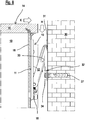
figure 8 shows a sectional view of the hanging-bracket device offigures 1 to 7 when constrained to a wall cupboard and thus constrained is positioned in use on a rod fixed to a wall; -
figures 9 and10 show similar views to what is shown infigure 8 in subsequent phases illustrating the fixing modes and stable positioning to the wall in an anti-disengagement position. - With reference first of all to all of the figures, the hanging-bracket device according to the invention is indicated as a whole with 10, and consists of the combination of a
plate 11, having a substantially elongated rectangular configuration, and anarm 12 articulately constrained to theplate 11, suitable for collaborating with a bearing element such as a support orrod 32 fixed to awall 30 by means ofdowels 27. - The
plate 11 is destined for being substantially fixed to ashoulder 13 of awall cupboard 14, of which - to simplify the drawing - only an upper edge is illustrated, which is composed of thesame shoulder 13, anupper top 15 and a possiblerear lining 16. - The partial fixing of the
plate 11 to theshoulder 13 is actuated in a known way, by means of a plurality ofpins 17 which extend from a side of the same and through further fixing means 18. - The
arm 12 is hinged, or articulated, by means ofpins 19 to aspindle nut 20 which is screwed onto ascrew 21 of theplate 11. - As can be clearly seen from the drawings, the
screw 21 is axially constrained to theplate 11, but with the possibility of rotation, extending between twoopposite walls 49, one of which is shown. - For this purpose, the head of the
screw 21 is composed of afirst gear 22 coupled at 90° with asecond gear 23, which, on the opposite side to the teeth, has aseat 24 for a maneuvering screwdriver. - It is consequently evident that the rotation of the
gear 23 causes, through thegear 22, a rotation of thescrew 21 and therefore the translation in one of the two directions of the arrow F1 of thespindle nut 20, and consequently the movement of thearm 12. - This causes a vertical adjustment of the position of the
arm 12 with respect to theplate 11. - The position of the
arm 12 with respect to theplate 11 can also be horizontally adjusted (in depth), by means of ascrew 25 which is screwed onto aseat 26 of theplate 11 itself and is anchored by means of its enlarged head to avertical slot 28 of thearm 12. The head of the screw has a cross-shaped seat for a maneuvering screwdriver. - Also in this case, it is evident how, by acting on the
regulation screw 25, a variation is caused in the angle formed by thearm 22 with theplate 11, and consequently an adjustment in depth of the position of thewall cupboard 14 with respect to awall 30. - The
arm 12 is also provided, at one of its free ends, with a hookingelement 31 destined for being hooked to a support orrod 32 fixed to thewall 30 by means ofdowels 27. - The kinematic mechanisms for adjustment in height and depth described above for purely illustrative and non-limiting purposes, are of the type known to skilled persons in the field, and may also be different.
- Adjustable concealed hanging-bracket devices of the type described above are fixed to the
shoulder 13 of the wall cupboard 14 (manually or also automatically), by inserting - with interference - thepins 17 into respective seats of the shoulder 13 (figures 8 ,9 and10 ). - According to the invention, the
arm 12 has a square-shaped form in its intermediate position that defines astop 33 positioned between an end of the arm shaped as ahooking element 31 and an opposite end of the arm having a box-shaped form where the constrainingpins 19 to thespindle nut 20, which is screwed onto ascrew 21 of theplate 11, are positioned. - Said
stop 33 of thearm 12 is suitable for being positioned beneath the bearing element in the form of a support orrod 32 fixed to thewall 30 when the hanging-bracket device or piece of furniture are arranged in an operational position. Said supportingelement 32 preferably provides a protrudingportion 34 formed perpendicularly to saidwall 30 and suitable for being abutted against saidstop 33. - This arrangement creates an extremely stable and precise anti-disengagement system which ensures the stable positioning of the
wall cupboard 14 andrelative hanging bracket 10 with respect to the rod of thebearing element 32 constrained to thewall 30. - It should be noted how, through the present invention, a hanging-bracket device is defined, having an anti-disengagement function which does not require any additional part as, on the contrary, has so far been necessary.
- The functioning of this hanging-bracket device is very clearly shown in
figures 8 to 10 which illustrate consecutive phases of the assembly of thewall cupboard 14 containing said hanging-bracket device 10. - Once the hanging-
bracket device 10 according to the invention has been firmly fixed to thewall cupboard 14 with thearm 12 rotated forwards and detached from theplate 11, the furniture is moved towards the wall according to an arrow K. Once the end with thehooking element 31 of thearm 12 has been brought above the bearing element in the form of a support orrod 32, fixed to thewall 30, thewall cupboard 14 is lowered according to the arrow H thus hooking thewall cupboard 14 to thewall 30, as shown infigure 9 . - At this point, the usual adjustments are effected by inserting a screwdriver G to actuate the relative adjustment kinematic mechanisms.
- When this operation has been completed, the
wall cupboard 14 is accompanied until it rests on thewall 30 reaching the correct assembly position shown infigure 10 . - The present invention is thus utilized as, through this movement, a stable anti-disengagement position of the hanging-bracket device is obtained.
- With this movement and positioning of parts, in fact, the
stop 33 of thearm 12 is positioned beneath the bearing element in the form of a support orrod 32 fixed to thewall 30. - In particular, as is shown in the example illustrated, the
protruding portion 34 of the bearing element in the form of a support orrod 32, as it is perpendicular to saidwall 30, is specifically abutted above thestop 33. - It can therefore be seen how, without any additional element or parts to the hanging-bracket device through the arrangement of the
stop 33 simply obtained directly in the formation phase of thearm 12, the desired objective is achieved, solving the problem of anti-disengagement. - The objective mentioned in the preamble of the description has therefore been achieved.
- The protection scope of the invention is therefore defined by the following claims.
Claims (5)
- A hanging-bracket device (10) for wall cupboards incorporating an anti-disengagement function comprising, in combination: a fixing plate (11) to a shoulder (13) of a wall cupboard (14), a hooking element (31) of said hanging bracket (10) to a bearing element (32) fixed to a wall (30), adjustment kinematic mechanisms in depth and in height (in horizontal and in vertical) of the hooking element (31) with respect to the plate (11), being provided between said plate (11) and said hooking element (31), wherein said hooking element (31) is positioned at the end of an articulated arm (12), by means of pins (19), to said plate (11), characterized in that said arm (12) has a stop (33) suitable for being positioned beneath said bearing element (32) fixed to a wall (30), acting when said wall cupboard (14) containing said hanging-bracket device is positioned in use on said wall (30).
- The hanging-bracket device according to claim 1, characterized in that said stop (33) is positioned between an end of said arm (12) shaped as a hooking element (31) and an opposite box-shaped end where said arm (12) is articulated, by means of pins (19) to said plate (11).
- The hanging-bracket device according to one or more of the previous claims, characterized in that said stop (33) is defined by an intermediate portion of said arm (12) in a square-shaped form.
- The hanging-bracket device according to one or more of the previous claims, characterized in that said bearing element (32) fixed to said wall (30) comprises a support or rod (32).
- The hanging-bracket device according to one or more of the previous claims, characterized in that said supporting element (32) provides a portion (34) protruding perpendicularly with respect to said wall (30) suitable for being abutted against said stop (33).
Applications Claiming Priority (1)
| Application Number | Priority Date | Filing Date | Title |
|---|---|---|---|
| ITUB2016A000105A ITUB20160105A1 (en) | 2016-01-28 | 2016-01-28 | REGGIPENSILE DEVICE FOR HANGING CABINET INCORPORATING THE ANTI-SLIP FUNCTION |
Publications (1)
| Publication Number | Publication Date |
|---|---|
| EP3199063A1 true EP3199063A1 (en) | 2017-08-02 |
Family
ID=55919829
Family Applications (1)
| Application Number | Title | Priority Date | Filing Date |
|---|---|---|---|
| EP17151725.3A Pending EP3199063A1 (en) | 2016-01-28 | 2017-01-17 | Suspension fitting for wall cupboard incorporating an anti-disengagement function |
Country Status (2)
| Country | Link |
|---|---|
| EP (1) | EP3199063A1 (en) |
| IT (1) | ITUB20160105A1 (en) |
Cited By (1)
| Publication number | Priority date | Publication date | Assignee | Title |
|---|---|---|---|---|
| CN111182817A (en) * | 2017-10-03 | 2020-05-19 | 莱昂纳多有限责任公司 | Hidden tear-resistant suspension bracket assembly with accurate depth adjustment |
Citations (5)
| Publication number | Priority date | Publication date | Assignee | Title |
|---|---|---|---|---|
| EP1008316A1 (en) | 1998-12-10 | 2000-06-14 | Industrias Auxiliares, S.A. | Mounting device for kitchen furniture and the like |
| DE20103728U1 (en) | 2001-03-03 | 2001-05-03 | Hettich Paul Gmbh & Co | Closet hanging device |
| WO2004032681A1 (en) | 2002-10-10 | 2004-04-22 | Leonardo S.R.L. | Concealed adjustable mounting device with improved fixing system to the top corner of wall-furniture |
| WO2009077828A1 (en) | 2007-12-18 | 2009-06-25 | Leonardo S.R.L. | Hidden and adjustable support for the wall mounting of a suspended furniture piece |
| EP2807954A1 (en) | 2013-05-27 | 2014-12-03 | Leonardo S.r.L. | Perfected anti-disengagement system for wall cupboards |
-
2016
- 2016-01-28 IT ITUB2016A000105A patent/ITUB20160105A1/en unknown
-
2017
- 2017-01-17 EP EP17151725.3A patent/EP3199063A1/en active Pending
Patent Citations (5)
| Publication number | Priority date | Publication date | Assignee | Title |
|---|---|---|---|---|
| EP1008316A1 (en) | 1998-12-10 | 2000-06-14 | Industrias Auxiliares, S.A. | Mounting device for kitchen furniture and the like |
| DE20103728U1 (en) | 2001-03-03 | 2001-05-03 | Hettich Paul Gmbh & Co | Closet hanging device |
| WO2004032681A1 (en) | 2002-10-10 | 2004-04-22 | Leonardo S.R.L. | Concealed adjustable mounting device with improved fixing system to the top corner of wall-furniture |
| WO2009077828A1 (en) | 2007-12-18 | 2009-06-25 | Leonardo S.R.L. | Hidden and adjustable support for the wall mounting of a suspended furniture piece |
| EP2807954A1 (en) | 2013-05-27 | 2014-12-03 | Leonardo S.r.L. | Perfected anti-disengagement system for wall cupboards |
Cited By (2)
| Publication number | Priority date | Publication date | Assignee | Title |
|---|---|---|---|---|
| CN111182817A (en) * | 2017-10-03 | 2020-05-19 | 莱昂纳多有限责任公司 | Hidden tear-resistant suspension bracket assembly with accurate depth adjustment |
| CN111182817B (en) * | 2017-10-03 | 2022-02-11 | 莱昂纳多有限责任公司 | Hidden tear-resistant suspension bracket assembly with accurate depth adjustment |
Also Published As
| Publication number | Publication date |
|---|---|
| ITUB20160105A1 (en) | 2017-07-28 |
Similar Documents
| Publication | Publication Date | Title |
|---|---|---|
| EP3457890B1 (en) | Automatically activated anti-disengagement system for a hidden hanging bracket for wall cupboards | |
| DK3157386T3 (en) | HIDDEN HANGING CONSOLE WITH AN IMPROVED WALL CABLE ANTI-DISCOVERY SYSTEM | |
| EP3057471B1 (en) | Hidden hanging bracket for wall cupboards | |
| DK3157387T3 (en) | A VISIBLE HANGING CONSOLE WITH AN IMPROVED ANTI-DISCHARGE SYSTEM FOR WALL CABINET | |
| EP1549177B1 (en) | Concealed adjustable mounting device with improved fixing system to the top corner of wall-furniture | |
| EP3199063A1 (en) | Suspension fitting for wall cupboard incorporating an anti-disengagement function | |
| EP2807954B1 (en) | Perfected anti-disengagement system for wall cupboards | |
| EP2916689B1 (en) | Perfected hanging bracket for the wall assembly of a wall-cupboard | |
| EP3340836B1 (en) | Improvements in mounting devices | |
| EP2149316A1 (en) | Improved mounting device for hanging furniture | |
| JP6815199B2 (en) | Wall-mounted cupboard free detachment prevention system | |
| EP3386347B1 (en) | Visible and adjustable hanging-bracket group for anchoring a wall cupboard to a wall, with perfected fixing means to the shoulder of the wall cupboard | |
| WO2014206528A1 (en) | Hidden hanging-bracket with regulation from above equipped with a perfected anti-disengagement device |
Legal Events
| Date | Code | Title | Description |
|---|---|---|---|
| PUAI | Public reference made under article 153(3) epc to a published international application that has entered the european phase |
Free format text: ORIGINAL CODE: 0009012 |
|
| STAA | Information on the status of an ep patent application or granted ep patent |
Free format text: STATUS: THE APPLICATION HAS BEEN PUBLISHED |
|
| AK | Designated contracting states |
Kind code of ref document: A1 Designated state(s): AL AT BE BG CH CY CZ DE DK EE ES FI FR GB GR HR HU IE IS IT LI LT LU LV MC MK MT NL NO PL PT RO RS SE SI SK SM TR |
|
| AX | Request for extension of the european patent |
Extension state: BA ME |
|
| STAA | Information on the status of an ep patent application or granted ep patent |
Free format text: STATUS: REQUEST FOR EXAMINATION WAS MADE |
|
| 17P | Request for examination filed |
Effective date: 20180130 |
|
| RBV | Designated contracting states (corrected) |
Designated state(s): AL AT BE BG CH CY CZ DE DK EE ES FI FR GB GR HR HU IE IS IT LI LT LU LV MC MK MT NL NO PL PT RO RS SE SI SK SM TR |
|
| STAA | Information on the status of an ep patent application or granted ep patent |
Free format text: STATUS: EXAMINATION IS IN PROGRESS |
|
| 17Q | First examination report despatched |
Effective date: 20180713 |
|
| STAA | Information on the status of an ep patent application or granted ep patent |
Free format text: STATUS: EXAMINATION IS IN PROGRESS |
|
| STAA | Information on the status of an ep patent application or granted ep patent |
Free format text: STATUS: EXAMINATION IS IN PROGRESS |