EP3198822B1 - Computer network packet flow controller - Google Patents
Computer network packet flow controller Download PDFInfo
- Publication number
- EP3198822B1 EP3198822B1 EP15844361.4A EP15844361A EP3198822B1 EP 3198822 B1 EP3198822 B1 EP 3198822B1 EP 15844361 A EP15844361 A EP 15844361A EP 3198822 B1 EP3198822 B1 EP 3198822B1
- Authority
- EP
- European Patent Office
- Prior art keywords
- aipr
- session
- packet
- packets
- address
- Prior art date
- Legal status (The legal status is an assumption and is not a legal conclusion. Google has not performed a legal analysis and makes no representation as to the accuracy of the status listed.)
- Active
Links
Images


Classifications
-
- H—ELECTRICITY
- H04—ELECTRIC COMMUNICATION TECHNIQUE
- H04L—TRANSMISSION OF DIGITAL INFORMATION, e.g. TELEGRAPHIC COMMUNICATION
- H04L47/00—Traffic control in data switching networks
- H04L47/10—Flow control; Congestion control
- H04L47/24—Traffic characterised by specific attributes, e.g. priority or QoS
- H04L47/2483—Traffic characterised by specific attributes, e.g. priority or QoS involving identification of individual flows
-
- H—ELECTRICITY
- H04—ELECTRIC COMMUNICATION TECHNIQUE
- H04L—TRANSMISSION OF DIGITAL INFORMATION, e.g. TELEGRAPHIC COMMUNICATION
- H04L45/00—Routing or path finding of packets in data switching networks
- H04L45/38—Flow based routing
-
- H—ELECTRICITY
- H04—ELECTRIC COMMUNICATION TECHNIQUE
- H04L—TRANSMISSION OF DIGITAL INFORMATION, e.g. TELEGRAPHIC COMMUNICATION
- H04L45/00—Routing or path finding of packets in data switching networks
- H04L45/72—Routing based on the source address
-
- H—ELECTRICITY
- H04—ELECTRIC COMMUNICATION TECHNIQUE
- H04L—TRANSMISSION OF DIGITAL INFORMATION, e.g. TELEGRAPHIC COMMUNICATION
- H04L45/00—Routing or path finding of packets in data switching networks
- H04L45/74—Address processing for routing
-
- H—ELECTRICITY
- H04—ELECTRIC COMMUNICATION TECHNIQUE
- H04L—TRANSMISSION OF DIGITAL INFORMATION, e.g. TELEGRAPHIC COMMUNICATION
- H04L61/00—Network arrangements, protocols or services for addressing or naming
- H04L61/58—Caching of addresses or names
-
- H—ELECTRICITY
- H04—ELECTRIC COMMUNICATION TECHNIQUE
- H04L—TRANSMISSION OF DIGITAL INFORMATION, e.g. TELEGRAPHIC COMMUNICATION
- H04L67/00—Network arrangements or protocols for supporting network services or applications
- H04L67/14—Session management
- H04L67/142—Managing session states for stateless protocols; Signalling session states; State transitions; Keeping-state mechanisms
-
- H—ELECTRICITY
- H04—ELECTRIC COMMUNICATION TECHNIQUE
- H04L—TRANSMISSION OF DIGITAL INFORMATION, e.g. TELEGRAPHIC COMMUNICATION
- H04L67/00—Network arrangements or protocols for supporting network services or applications
- H04L67/14—Session management
- H04L67/146—Markers for unambiguous identification of a particular session, e.g. session cookie or URL-encoding
-
- H—ELECTRICITY
- H04—ELECTRIC COMMUNICATION TECHNIQUE
- H04L—TRANSMISSION OF DIGITAL INFORMATION, e.g. TELEGRAPHIC COMMUNICATION
- H04L67/00—Network arrangements or protocols for supporting network services or applications
- H04L67/50—Network services
- H04L67/56—Provisioning of proxy services
- H04L67/563—Data redirection of data network streams
-
- H—ELECTRICITY
- H04—ELECTRIC COMMUNICATION TECHNIQUE
- H04L—TRANSMISSION OF DIGITAL INFORMATION, e.g. TELEGRAPHIC COMMUNICATION
- H04L12/00—Data switching networks
- H04L12/28—Data switching networks characterised by path configuration, e.g. LAN [Local Area Networks] or WAN [Wide Area Networks]
- H04L12/2854—Wide area networks, e.g. public data networks
- H04L12/2856—Access arrangements, e.g. Internet access
- H04L12/2858—Access network architectures
- H04L12/2861—Point-to-multipoint connection from the data network to the subscribers
-
- H—ELECTRICITY
- H04—ELECTRIC COMMUNICATION TECHNIQUE
- H04L—TRANSMISSION OF DIGITAL INFORMATION, e.g. TELEGRAPHIC COMMUNICATION
- H04L69/00—Network arrangements, protocols or services independent of the application payload and not provided for in the other groups of this subclass
- H04L69/16—Implementation or adaptation of Internet protocol [IP], of transmission control protocol [TCP] or of user datagram protocol [UDP]
- H04L69/161—Implementation details of TCP/IP or UDP/IP stack architecture; Specification of modified or new header fields
-
- H—ELECTRICITY
- H04—ELECTRIC COMMUNICATION TECHNIQUE
- H04L—TRANSMISSION OF DIGITAL INFORMATION, e.g. TELEGRAPHIC COMMUNICATION
- H04L69/00—Network arrangements, protocols or services independent of the application payload and not provided for in the other groups of this subclass
- H04L69/22—Parsing or analysis of headers
Definitions
- the present invention relates to data routing and, more particularly, to routing packets in an IP network.
- IP The Internet Protocol
- IP serves as the de-facto standard for forwarding data messages (“datagrams”) between network devices connected with the Internet.
- IP delivers datagrams across a series of Internet devices, such as routers and switches, in the form of one or more data packets.
- Each packet has two principal parts: (1) a payload with the information being conveyed (e.g., text, graphic, audio, or video data), and (2) a header, known as an "IP header,” having the address of the network device to receive the packet(s) (the "destination device"), the identity of the network device that sent the packet (the "originating device”), and other data for routing the packet.
- IP Internet Protocol
- US2014/0092906A1 discloses a method of receiving a first packet of a connection between a client and a server, wherein the first packet is tagged with a tag comprising a member ID of a service node in a service cluster that includes a plurality of nodes having distinct member IDs.
- the method also includes mapping the member ID to the service node in a tag-to-node map; receiving a second packet of the connection, where the second packet is tagged with the tag comprising the member ID; determining the service node from the tag-to-node map; and forwarding the second packet to the service node.
- US2002/0044553A1 discloses a method for high-speed transport of voice, video and data packets for facilitating the convergence of multiple networking facilities into one, which allegedly should be Quality of Service (QoS) driven, and secure.
- the method should also allow for incorporating robust management features, for locally and remotely managing various nodes such as routers, switches, portable devices and other appurtenances including computers and communication links.
- the method provides for switching of data packets that comprise Internet Protocol (IP), Transmission Control Protocol (TCP), User Datagram Protocol (UDP), Internet Control Message Protocol (ICMP), and other packets, and includes signaling packet configurations.
- IP Internet Protocol
- TCP Transmission Control Protocol
- UDP User Datagram Protocol
- ICMP Internet Control Message Protocol
- the method allows for replacing one or more bits in the IP header address fields and replacing them with or adding to them unique virtual connection or virtual circuit (VC) identifiers for node-to-node, that is device-to-device, connectivity as well as for representing values or parameters for packet type, QoS, security, network management and node/link resources. Identifiers for the above parameters are developed and saved at each node as a switching table.
- VC virtual connection or virtual circuit
- IP's statelessness introduces various limitations.
- a stateless IP network inhibits or prevents: 1) user mobility in mobile networks, 2) session layer load balancing for packet traffic in the network, and 3) routing between private or overlapping networks.
- the art has responded to this problem by implementing tunneling protocols, which provide these functions.
- tunneling protocols transport IP datagrams to a destination along a route that normally is different than the route the datagram would have taken if it had not used a tunneling protocol.
- tunneling protocols undesirably introduce additional problems into the network. For example, tunneling requires additional overhead that can induce IP packet fragmentation, consequently introducing substantial network inefficiencies into a session.
- tunnels generally use more bandwidth than non-tunneled packets, and tunnel origination and termination requires additional CPU cycles per packet.
- tunnel addresses must be provisioned in advance, reducing flexibility.
- a packet flow controller ensures that, at least for flow in a forward direction, packets of a session follow the same path as the lead/first packet of that session, i.e., from a source device to a destination device. Details of various embodiments are discussed below.
- a network includes at least two nodes and at least one link between the nodes.
- Nodes can include computing devices (sometimes referred to as hosts or devices) and routers.
- Computers include personal computers, smart phones, automatic teller machines (ATMs) and many other types of equipment that include processors and network interfaces.
- Links include wired and wireless connections between pairs of nodes.
- nodes and/or links may be implemented completely in software, such as in a virtual machine, a software defined network, and using network function virtualization.
- Many networks include switches, which are largely transparent for purposes of this discussion. However, some switches also perform routing functions. For the present discussion, such routing switches are considered routers. Routers are described below.
- a node can be directly connected to one or more other nodes, each via a distinct link.
- Fig. 1 schematically shows a Node A directly connected to Node B via Link 1.
- each node has a unique network address to facilitate sending and receiving data.
- a network includes all the nodes addressable within the network according to the network's addressing scheme and all the links that interconnect the nodes for communication according to the network's addressing scheme.
- Node A, Node B, Node C,... Node F and all the links 1-8 together make up a network 100.
- a network is depicted as a cloud or as being enclosed within a cloud.
- Nodes initiate communications with other nodes via the network, and nodes receive communications initiated by other nodes via the network.
- a node may transmit/forward/send data (a message) to a directly connected (adjacent) node by sending the message via the link that interconnects the adjacent nodes.
- the message includes the network address of the sending node (the "source address") and the network address of the intended receiving node (the "destination address").
- a sending node can send a message to a non-adjacent node via one or more other nodes.
- Node D may send a message to Node F via Node B.
- the node(s) between the source and the destination forward the message until the message reaches its destination. Accordingly, to operate properly, network protocols enable nodes to learn or discover network addresses of non-adjacent nodes in their network.
- Nodes communicate via networks according to protocols, such as the well-known Internet Protocol (IP) and Transmission Control Protocol (TCP).
- IP Internet Protocol
- TCP Transmission Control Protocol
- the protocols are typically implemented by layered software and/or hardware components, such as according to the well-known seven-layer Open System Interconnect (OSI) model.
- OSI Open System Interconnect
- IP operates at OSI Layer 3 (Network Layer)
- TCP operates largely at OSI Layer 4 (Transport Layer).
- Each layer performs a logical function and abstracts the layer below it, therefore hiding details of the lower layer.
- Layer 3 may fragment a large message into smaller packets if Layer 2 (Data Link Layer) cannot handle the message as one transmission.
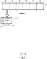
- Fig. 2 schematically illustrates a large message 200 divided into several pieces 202, 204, 206, 208, 210 and 212. Each piece 202-212 may then be sent in a separate packet, exemplified by packet 214.
- Each packet includes a payload (body) portion, exemplified by payload 216, and a header portion, exemplified at 218.
- the header portion 218 contains information, such as the packet's source address, destination address and packet sequence number, necessary or desirable for: 1) routing the packet to its destination, 2) reassembling the packets of a message, and 3) other functions provided according to the protocol.
- a trailer portion is also appended to the payload, such as to carry a checksum of the payload or of the entire packet. All packets of a message need not be sent along the same path, i.e., through the same nodes, on their way to their common destination. It should be noted that although IP packets are officially called IP datagrams, they are commonly referred to simply as packets.
- TCP protocol data units TCP protocol data units
- packet is used to refer to PDUs and datagrams, as well as Ethernet frames.
- IP encapsulates a TCP packet by adding an IP header to the TCP packet to produce an IP packet.
- packets sent at a lower layer can be thought of as being made up of packets within packets.
- a component operating according to a protocol examines or modifies only information within a header and/or trailer that was created by another component, typically within another node, operating according to the same protocol. That is, conventionally, components operating according to a protocol do not examine or modify portions of packets created by other protocols.
- some layers translate addresses.
- Some layers include layer-specific addressing schemes. For example, each end of a link is connected to a node via a real (e.g., electronic) or virtual interface, such as an Ethernet interface.
- a real (e.g., electronic) or virtual interface such as an Ethernet interface.
- each interface has an address, such as a media access control (MAC) address.
- MAC media access control
- Layer 3 converts IP addresses to MAC addresses.
- a router typically acts as a node that interconnects two or more distinct networks or two or more sub-networks (subnets) of a single network, thereby creating a "network of networks" (i.e., an internet).
- a router has at least two interfaces, where each interface connects the router to a different network, as exemplified in Fig. 3 .
- a router receives a packet via one interface from one network, it uses information stored in its routing table to direct the packet to another network via another interface.
- the routing table contains network/next hop associations. These associations tell the router that a particular destination can optimally be reached by sending the packet to a specific router that represents a next hop on the way to the final destination.
- Router 1 300 For example, if Router 1 300 receives a packet, via its Interface 1 304, from Network 1 302, and the packet is destined to a node in Network 3 306, the Router 1 300 consults its router table and then forwards the packet via its Interface 2 308 to Network 2 310. Network 2 310 will then forward the packet to Network 3 306.
- the next hop association can also be indicated in the routing table as an outgoing (exit) interface to the final destination.
- ISPs Internet service providers
- ISPs Internet service providers
- ISPs also employ routers in hierarchies to carry traffic between their customers' gateways, to interconnect with other ISPs, and to interconnect with core routers in the Internet backbone.
- a router is considered a Layer 3 device because its primary forwarding decision is based on the information in the Layer 3 IP packet-specifically the destination IP address.
- a conventional router does not look into the actual data contents (i.e., the encapsulated payload) that the packet carries. Instead, the router only looks at the Layer 3 addresses to make a forwarding decision, plus optionally other information in the header for hints, such as quality of service (QoS) requirements.
- QoS quality of service
- a router when a router receives a packet via one interface from one network, the router uses its routing table to direct the packet to another network.
- Table 1 lists information typically found in a basic IP routing table.
- Table 1 Destination Partial IP address (Expressed as a bit-mask) or Complete IP address of a packet's final destination Next hop IP address to which the packet should be forwarded on its way to the final destination Interface Outgoing network interface to use to forward the packet Cost/Metric Cost of this path, relative to costs of other possible paths.
- Routing tables may be filled in manually, such as by a system administrator, or dynamically by the router.
- the router uses routing protocols to exchange information with other routers and, thereby, dynamically learn about surrounding network or internet topology. For example, routers announce their presence in the network(s), more specifically, the range of IP addresses to which the routers can forward packets. Neighboring routers update their routing tables with this information and broadcast their ability to forward packets to the network(s) of the first router. This information eventually spreads to more distant routers in a network. Dynamic routing allows a router to respond to changes in a network or internet, such as increased network congestion, new routers joining an internet and router or link failures.
- a routing table therefore provides a set of rules for routing packets to their respective destinations.
- a router examines the packet's contents, such as its destination address, and finds the best matching rule in the routing table.
- the rule essentially tells the router which interface to use to forward the packet and the IP address of a node to which the packet is forwarded on its way to its final destination IP address.
- each routing table lists, for all reachable destinations, the address of the next node along a path to that destination, i.e., the next hop. Assuming that the routing tables are consistent, a simple algorithm of each router relaying packets to their destinations' respective next hop suffices to deliver packets anywhere in a network.
- Hop-by-hop is a fundamental characteristic of the IP Internetwork Layer and the OSI Network Layer.
- each router's routing table typically merely contains information sufficient to forward a packet to another router that is "closer" to the packet's destination, without a guarantee of the packet ever being delivered to its destination.
- a packet finds its way to its destination by visiting a series of routers and, at each router, using then-current rules to decide which router to visit next, with the hope that at least most packets ultimately reach their destinations.
- the rules may change between two successive hops of a packet or between two successive packets of a message, such as if a router becomes congested or a link fails. Two packets of a message may, therefore, follow different paths and even arrive out of order.
- the path typically is dynamically determined as the packet traverses the various routers. This may be referred to as "natural routing," i.e., a path is determined dynamically as the packet traverses the internet.
- packets sent by the destination node back to the source node may follow different paths than the packets from the source node to the destination node.
- a client computer node establishes a session with a server computer node, and the client and server exchange packets within the session.
- a client computer executing a browser may establish a session with a web server.
- the client may send one or more packets to request a web page, and the web server may respond with one or more packets containing contents of the web page.
- this back-and-forth exchange of packets may continue for several cycles.
- packets may be sent asynchronously between the two nodes.
- a session has its conventional meaning; namely, it is a plurality of packets sent by one node to another node, where all the packets are related, according to a protocol.
- a session may be thought of as including a lead (or initial) packet that begins the session, and one or more subsequent packets of the session.
- a session has a definite beginning and a definite end.
- a TCP session is initiated by a SYN packet.
- the end may be defined by a prescribed packet or series of packets.
- a TCP session may be ended with a FIN exchange or an RST.
- the end may be defined by lack of communication between the nodes for at least a predetermined amount of time (a timeout time).
- a TCP session may be ended after a defined timeout period. Some sessions include only packets sent from one node to the other node. Other sessions include response packets, as in the web client/server interaction example.
- a session may include any number of cycles of back-and-forth communication, or asynchronous communication, according to the protocol, but all packets of a session are exchanged between the same client/server pair of nodes.
- a session is also referred to herein as a series of packets.
- a computer having a single IP address may provide several services, such as web services, e-mail services and file transfer (FTP) services.
- Each service is typically assigned a port number in the range 0-65,535 that is unique on the computer.
- a service is, therefore, defined by a combination of the node's IP address and the service's port number. Note that this combination is unique within the network the computer is connected to, and it is often unique within an internet.
- a single node may execute many clients. Therefore, a client that makes a request to a service is assigned a unique port number on the client's node, so return packets from the service can be uniquely addressed to the client that made the request.
- socket means an IP address-port number combination.
- each service has a network-unique, and often internet-unique, service socket, and a client making a request of a service is assigned a network-unique, and sometimes internet-unique, client socket.
- source client and destination service are used when referring to a client that sends packets to make requests of a service and the service being requested, respectively.
- Illustrative embodiments of the present invention overcome these and other shortcomings by ensuring that subsequent packets of a session follow the same path as the lead packet of the session, at least in the forward direction, i.e., from the source client to the destination service.
- the subsequent packets traverse at least a subset of the routers the lead packet traverses between the source client and the destination service.
- Each router in the subset is referred to herein as an intermediate node or waypoint, although the waypoints are not necessarily predetermined before the lead packet is sent by the source client.
- the lead packet may be naturally routed. Nevertheless, the path taken by the lead packet establishes the waypoints, and the subsequent packets traverse the same waypoints, and in the same order, as the lead packet.
- some packets may be dropped along the way, as is typical in an IP network or internet, such as by an overloaded router or due to corruption of the packet by a link.
- all the packets sent by the source client need not reach the session's destination service and, consequently, all the packets sent by the source client need not traverse all the waypoints.
- subsequent packets that do reach the destination service must traverse all the waypoints.
- all the packets means all the packets that reach their respective destinations.
- metrics collected at one of the waypoints represent all the packets of the session. These metrics are not diluted by packets that bypass the waypoint, because no packet of the session can bypass any waypoint.
- Security functions, such as inspection for malicious packets, performed at one waypoint are sure to be performed on all packets of the session.
- Some embodiments of the present invention also ensure that return packets from the destination service to the source client also follow the same path, i.e., traverse the waypoints, but in reverse order.
- This reverse flow control enables use of paths, such as via proprietary networks, that might not otherwise be available by naturally routing the return packets.
- a packet flow controller (also referred to herein as an augmented IP router ("AIPR")) ensures that subsequent packets of a session follow the same path as the lead packet of the session, as discussed above.
- An AIPR also performs conventional routing functions.
- Fig. 4 is a schematic diagram illustrating a hypothetical set of interconnected networks 400, 402, 404 and 406, i.e., an internet. Each network 400-406 includes a number of routers and AIPRs, not all of which are necessarily shown.
- Network 400 includes AIPR1 408 and router 410.
- Network 400 may be, for example, a network of a telecommunications carrier.
- Network 402 includes a router 412 and AIPR 2 414.
- Network 402 may be, for example, a network of a first ISP.
- Network 404 includes a router 416 and AIPR 3 418.
- Network 404 may be, for example, the Internet backbone or a portion thereof.
- Network 406 includes a router 420, AIPR 4 422 and another router 424.
- Network 406 may be, for example, a network of a second ISP.
- a source client node 426 initiates a session with a destination service node 428.
- the source client 426 may request a web page
- the destination service node 428 may include a web server.
- the source client 426 may, for example, be part of a first local area network (LAN) (not shown) within a first corporation, and the LAN may be connected to the telecommunications carrier network 400 via a gateway router 430 operated by the corporation.
- the destination service node 428 may be operated by a second corporation, and it may be part of a second LAN (not shown) coupled to the network 406 of the second ISP via a gateway router 432 operated by the second corporation.
- each AIPR waypoint
- the packet traverses records information that eventually enables the waypoint to be able to identify its immediately previous waypoint and its immediately next waypoint, with respect to the session.
- AIPR 1 408 automatically identifies the lead packet as being an initial packet of the session.
- AIPR 1 408 may use various techniques to identify the beginning of a session, as noted above and as discussed in more detail below.
- AIPR 1 408 becomes the first waypoint along a path the lead packet eventually follows.
- AIPR 1 408 assigns a unique identifier to the session and stores information about the session in the AIPR's database to enable the AIPR 1 408 to identify subsequent packets of the session.
- AIPR 1 408 reads the client socket/service socket number pair in the lead packet and stores the client socket/service socket number pair in a database to uniquely identify the session. This enables the AIPR 1 408 to identify the subsequent packets as being part of the session, because all subsequent packets of the session will contain the same client socket/service socket number pair.
- AIPR 1 408 sets a flag in its database to indicate the lead packet has not traversed any other AIPR before reaching AIPR 1 408. This flag may be used later, for example when the AIPR 1 408 handles return packets. AIPR 1 408 may be able to identify the lead packet as not having traversed any other AIPR by lack of any modification to the packet. Packet modification is described below.
- AIPR 1 408 modifies the lead packet to indicate the lead packet has been handled by an AIPR.
- the AIRP 1 408 stores the unique identifier of the session and, if not included in the unique identifier, the AIRP's network address in the packet to produce a modified lead packet.
- Subsequent AIPRs, if any, that handle the (now modified) lead packet use this modification to identify the lead packet as a lead packet that has been handled by an AIPR, and to indicate that subsequent packets of the session should be routed the same way as the lead packet is routed.
- AIPR 1 408 assigns a port number on the interface over which AIRP 1 408 will forward the lead packet.
- the AIPR's network address and this port number, in combination, may be used as a unique identifier of the session, at least from the point of view of the next AIPR along the path.
- AIPR 1 408 may include the AIPR's network address-port number combination in the modified lead packet.
- the next AIPR along the path may assume that subsequent packets sent from this network address-port number combination are part of, or likely to be part of, the session.
- AIPR 1 408 then forwards the lead packet naturally.
- the lead packet traverses an unspecified number of nodes of network 400 until it reaches router 410, which naturally routes the lead packet to network 402. Assume the router 410 forwards the lead packet to AIPR 2 414 in network 402.
- AIPR 2 414 detects the modification to the lead packet, identifying a need for special treatment.
- AIPR 2 414 becomes the second waypoint along the path the lead packet will follow.
- AIPR 2 414 stores in its database the network address of AIPR 1 408 and the port number assigned by AIRP 1 408, in association with a unique identifier of the session, such as the client and server socket number pair, thus identifying the previous waypoint along the path in association with the session.
- each waypoint learns the network address and port number of the previous waypoint along this session's path and uses a related association device (an "associator”) to associate this information with a session identifier. This information may be used later to forward return packets, from waypoint to waypoint, back to the source client 426.
- AIPR 2 414 assigns a port number on the interface over which the lead packet was received.
- the AIPR's network address and this port number, in combination, may be used as a unique identifier of the session, at least from the point of view of AIPR 1 408.
- subsequent packets addressed to this network address-port number combination may be assumed to be, or at least are likely to be, part of the session.
- AIPR 2 414 sends a packet back to AIPR 1 408 to inform AIPR 1 408 of the network address-port number combination, in association with the identification of the session.
- the network address-port number combination are sent to AIPR 1 408 later, in connection with a return packet, as described below.
- AIPR 1 408 learns a network address-port number combination unique to the session, and AIPR 1 408 sends subsequent packets to that address-port combination, rather than naturally forwarding the subsequent packets.
- each waypoint learns the network address and port number of the next waypoint along this session's path. This information is used to forward subsequent packets, from waypoint to waypoint, forward to the destination service 428, along the same path as the lead packet.
- This kind of routing is unlike any routing taught by the prior art known to the inventors.
- AIPR 2 214 modifies the lead packet to include the network address of AIPR 2 214, and then forwards the lead packet naturally. As with AIPR 1 408, in some embodiments AIPR 2 214 assigns a port number on the interface over which AIPR 2 214 forwards the packet, and the network address of AIPR 2 214 and the port number are included in the modified lead packet AIPR 2 214 sends.
- the lead packet traverses an unspecified number of nodes of network 402, until it reaches router 412, which naturally routes the lead packet to network 404. Assume the router 416 forwards the lead packet to AIPR 3 418.
- AIPR 3 418 becomes the third waypoint along the path the lead packet will follow.
- AIPR 3 418 operates much as AIPR 2 414.
- the lead packet is then forwarded to network 406, where it traverses AIPR 4 422, which becomes the fourth waypoint.
- AIPR 422 Three scenarios are possible with respect to the last AIPR 422 (AIPR 4) along the path to the destination service 428.
- one or more AIPRs relatively close to a destination service are provisioned to handle lead packets for the destination service.
- the AIPRs may be so provisioned by storing information in their databases to identify the destination service, such as by the service socket number or other unique identifier of the service.
- These "terminus" AIPRs broadcast their ability to forward packets to the destination service.
- a terminus AIPR is an AIPR that can forward packets to a destination service, without the packets traversing another AIPR.
- a terminus AIPR recognizes a lead packet destined to a service that terminates at the AIPR by comparing the destination service socket number to the information provisioned in the AIPR's database.
- AIPR 4 422 may restore the lead packet to its original form, i.e., the form the lead packet had when the source client 426 sent the lead packet, or as the packet might have been modified by the router 430, such as a result of network address translation (NAT) performed by the router 430.
- the lead packet may be restored to a form that does not include any of the modifications made by the waypoints 408, 414 and 418.
- AIPR 4 422 then forwards the lead packet to the destination service 428.
- AIPR 4 422 stores information in its database identifying AIRP 3 418 as the previous AIPR for this session.
- AIPR 4 422 is not provisioned with information about the destination service 428.
- AIPR 4 422 may operate much as AIPR 2 414 and AIPR 3 418 operate.
- AIPR 4 422 modifies and naturally forwards the lead packet, and the lead packet is eventually delivered to the destination service 428.
- the destination service 428 responds to the lead packet. For example, if the lead packet is a SYN packet to initiate a TCP session, the destination service 428 responds with an ACK or SYN/ACK packet.
- AIPR 4 422 recognizes the return packet as being part of the session, such as based on the source client/destination service network address/port number pairs in the return packet. Furthermore, because the return packet was sent by the destination service 428, and not another AIPR, AIPR 4 422 recognizes that it is the last AIPR along the path for this service.
- AIPR 4 422 stores information in its database indicating AIPR 4 422 is a terminus AIPR. If AIPR 4 422 receives subsequent packets of the session, AIPR 4 422 may restore the subsequent packets to their original forms, i.e., the forms the subsequent packets had when the source client 426 sent the subsequent packets, or as the packets might have been modified by the router 430, such as a result of network address translation (NAT) performed by the router 430. AIPR 4 422 forwards the subsequent packets to the destination service 428.
- NAT network address translation
- AIRP 4 422 modifies the return packet to include a port number on the interface AIPR 4 422 received the lead packet from AIPR 3 418, as well as the network address of AIPR 4 422. AIPR 4 422 then forwards the return packet to AIPR 3 418. Although the return packet may be forwarded by other routers, AIPR 4 422 specifically addresses the return packet to AIPR 3 418. This begins the return packet's journey back along the path the lead packet traveled, through all the waypoints traversed by the lead packet, in reverse order. Thus, the return packet is not naturally routed back to the source client 426. This kind of return packet routing is unlike any routing taught by the prior art known by the inventors.
- AIPR 3 418 receives the modified return packet and, because the return packet was addressed to the port number AIPR 3 418 previously assigned and associated with this session, AIPR 3 418 can assume the return packet is part of, or likely part of, the session. AIPR 3 418 copies the network address and port number of AIPR 4 422 from the return packet into the AIPR's database as the next waypoint for this session. If AIPR 3 418 receives subsequent packets of the session, AIPR 3 418 forwards them to the network address and port number of the next waypoint, i.e., AIPR 4 422.
- the AIPR forwards subsequent packets to the next AIPR, rather than naturally routing the subsequent packets.
- AIPR 3 418 forwards the return packet to AIPR 2 414, whose network address and port number were stored in the database of AIPR 3 418 and identified as the previous waypoint of the session. Likewise, each of the waypoints along the path back to the source client 426 forwards the return packet to its respective previous waypoint.
- the waypoint may restore the return packet to its original form, i.e., the form the return packet had when the destination service 428 sent the return packet, or as the packet might have been modified by the router 430, such as a result of network address translation (NAT) performed by the router 430.
- NAT network address translation
- the first waypoint set a flag in its database to indicate the lead packet had not traversed any other waypoint before reaching the first waypoint. This flag is used to signal the first waypoint to restore the return packet and forward the restored return packet to the source client 426. The first waypoint forwards the return packet to the source client 426. Subsequent return packets are similarly handled.
- the last AIPR to receive the lead packet has a network address equal to the network address of the destination service.
- the destination service network address may be given to a gateway router/AIPR, and the gateway router/AIPR may either process the service request or its router table may cause the packet to be forwarded to another node to perform the service.
- the last AIPR may restore the lead packet and subsequent packets, as described above.
- a waypoint should be able to identify a lead packet of a session.
- Various techniques may be used to identify lead packets. Some of these techniques are protocol-specific. For example, a TCP session is initiated according to a well-known three-part handshake involving a SYN packet, a SYN-ACK packet and an ACK packet.
- a waypoint can identify a beginning of a session and, in many cases, an end of the session. For example, A TCP session may be ended by including a FIN flag in a packet and having the other node send an ACK, or by simply including an RST flag in a packet.
- each waypoint stores information about each session, such as the source client/destination service network address/port number pairs, the waypoint can identify the session with which each received packet is associated.
- the waypoint can follow the protocol state of each session by monitoring the messages and flags, such as SYN and FIN, sent by the endpoints of the session and storing state information about each session in its database.
- SYN and FIN Such stateful monitoring of packet traffic is not taught by the prior art known to the inventor. Instead, the prior art teaches away from this type of session.
- a SYN packet may be re-transmitted-each SYN packet does not necessarily initiate a separate session.
- the waypoint can differentiate between SYN packets that initiate a session and re-transmitted SYN packets based on, for example, the response packets.
- the waypoint may use a timer. After a predetermined amount of time, during which no packet is handled for a session, the waypoint may assume the session is ended. Such a timeout period may also be applied to sessions using protocols that define end sequences.
- Table 2 describes exemplary techniques for identifying the beginning and end of a session, according to various protocols. Similar techniques may be developed for other protocols, based on the definitions of the protocols.
- Table 2 Protocol Destination Port Technique for Start/End Determination TCP Any Detect start on the first SYN packet from a new address/port unique within the TCP protocol's guard time between address/port reuse. Following the TCP state machine to determine an end (FIN exchange, RST, or guard timeout).
- UDP - TFTP 69 Trap on the first RRQ or WRQ message to define a new session, trap on an undersized DAT packet for an end of session.
- UDP-SNMP 161, 162 Trap on the message type, including GetRequest, SetRequest, GetNextRequest, GetBulkRequest, InformRequest for a start of session, and monitor the Response for end of session.
- port 162 is used, and the flow of data generally travels in the "reverse" direction.
- UDP-SYSLOG 514 A single message protocol, thus each message is a start of session, and end of session.
- UDP-RTP Any RTP has a unique header structure, which can be reviewed/analyzed to identify a start of a session. This is not always accurate, but if used in combination with a guard timer on the exact same five-tuple address, it should work well enough.
- Each RTCP packet is sent periodically and can be considered a "start of session" with the corresponding RTCP response ending the session.
- This provides a very high quality way of getting analytics for RTCP at a network middle point, without using a Session Border Controller
- UDP-DNS Nameserver 53
- Each DNS query is a single UDP message and response. By establishing a forward session (and subsequent backward session) the Augmented router gets the entire transaction. This allows analytics to be gathered and manipulations that are appropriate at the Augmented router.
- UDP-NTP 123 Each DNS query/response is a full session. So, each query is a start, and each response is an end.
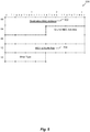
- Fig. 5 is a schematic layout of an Ethernet header 500, including a Destination MAC Address 502 and an 802.1q VLAN Tag 504.
- Fig. 6 is a schematic layout of an IP header 600, including a Protocol field 602, a Source IP Address 604 and a Destination IP Address 606.
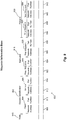
- Fig. 7 is a schematic layout of a TCP header 700, including a Source Port 702, a Destination Port 704, a Sequence Number 706, a SYN flag 708 and a FIN flag 710. These packets and the identified fields may be used to identify the beginning of a session, as summarized in Table 3.
- Protocol IP Header This defines the protocol in use and, for the TCP case, it must be set to a value that corresponds to TCP
- Source IP Address IP Header Defines the source IP Address of the initial packet of a flow.
- Destination IP Address IP Header Defines the destination IP Address of the initial packet of a flow.
- Source Port TCP Header Defines the flow instance from the source. This may reflect a client, a firewall in front of the client, or a carrier grade NAT.
- Destination Port TCP Header This defines the desired service requested, such as 80 for HTTP. Sequence Number TCP Header This is a random number assigned by the client. It may be updated by a firewall or carrier grade NAT. SYN Bit On TCP Header When the SYN bit is on, and no others, this is an initial packet of a session. It may be retransmitted if there is no response to the first SYN message.
- AIPR Augmented IP Router
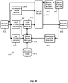
- Fig. 8 is a schematic block diagram of an AIPR (waypoint) 800 configured in accordance with illustrative embodiments of the invention.
- the AIPR 800 includes at least two network interfaces 802 and 804, through which the AIPR 800 may be coupled to two networks.
- the interfaces 802 and 804 may be, for example, Ethernet interfaces.
- the AIRP 800 may send and receive packets via the interfaces 802 and 804.
- a lead packet identifier 806 automatically identifies lead packets, as discussed herein.
- the lead packet identifier 806 identifies a lead packet when the lead packet identifier 806 receives a packet related to a session that is not already represented in the AIRP's information base 810, such as a packet that identifies a new source client/destination service network address/port number pair.
- each lead packet is an initial, non-dropped, packet of a series of packets (session).
- Each session includes a lead packet and at least one subsequent packet. The lead packet and all the subsequent packets are sent by the same source client toward the same destination service, for forward flow control. For forward and backward flow control, all the packets of the session are sent by either the source client or the destination service toward the other.
- a session (packet series) manager 808 is coupled to the lead packet identifier 806. For each session, the session manager assigns a unique identifier.
- the unique identifier may be, for example, a combination of the network address of the AIRP 800 or of the interface 802, in combination with a first port number assigned by the session manager 808 for receiving subsequent packets of this session.
- the unique identifier may further include the network address of the AIPR 800 or of the other interface 804, in combination with a second port number assigned by the session manager 808 for transmitting the lead packet and subsequent packets.
- This unique identifier is associated with the session.
- the session manager 808 stores information about the session in an information base 810. This information may include the unique identifier, in association with the original source client/destination service network address/port number pairs.
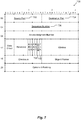
- Fig. 9 is a schematic layout of an exemplary waypoint information base 900. Each row represents a session.
- a session identification column 902 includes sub-columns for the source client 904 and the destination service 906. For each client 904, its network address 908 and port number 910 are stored. For each destination service 906, its network address 912 and port number 914 are stored. This information is extracted from the lead packet.
- State information about the session may be stored in a state column 915. This information may be used to statefully follow a series of packets, such as when a session is being initiated or ended.
- a backward column includes sub-columns for storing information 916 about a portion of the backward path, specifically to the previous AIPR.
- the backward path information 916 includes information 918 about the previous AIPR and information 920 about the present AIPR 800.
- the information 918 about the previous AIPR includes the AIPR's network address 922 and port number 924.
- the session manager 808 extracts this information from the lead packet, assuming the lead packet was forwarded by an AIPR. If, however, the present AIPR 800 is the first AIPR to process the lead packet, the information 918 is left blank as a flag.
- the information 920 about the present AIPR 800 includes the network address 926 of the interface 802 over which the lead packet was received, as well as the first port number 928 assigned by session manager 808.
- the waypoint information base 900 is also configured to store information 930 about a portion of the forward path, specifically to the next AIPR.
- This information 930 includes information 932 about the present AIPR 800 and information 934 about the next AIPR along the path, assuming there is a next AIPR.
- the information 932 includes the network address 936 of the interface over which the present AIPR will send the lead packet and subsequent packets, as well as the second port number 938 assigned by the session manager 808.
- the information 934 about the next AIPR along the path may not yet be available, unless the AIPR is provisioned with information about the forward path.
- the information 934 about the next AIPR includes its network address 940 and port number 942. If the information 934 about the next AIPR is not yet available, the information 934 may be filled in when the AIPR 800 processes a return packet, as described below.
- Some embodiments of the waypoint information base 900 may include the forward information 930 without the backward information 916. Other embodiments of the waypoint information base 900 may include the backward information 916 without the forward information 930.
- a lead packet modifier 812 is coupled to the session manager 808.
- the lead packet modifier 812 modifies the lead packet to store the unique identifier associated with the session.
- the original source client network address/port number pair, and the original destination service network address/port number pair, are stored in the modified lead packet, if necessary.
- the lead packet may be enlarged to accommodate the additional information stored therein, or existing space within the lead packet, such a vendor specific attribute field, may be used.
- Other techniques for transmitting additional information are protocol specific, for example with TCP, the additional information could be transmitted as a TCP Option field, or added to the SYN packet as data. In either case, the term session data block is used to refer to the information added to the modified lead packet.
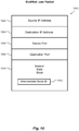
- Fig. 10 is a schematic diagram of an exemplary modified lead packet 1000 showing the original source and destination IP addresses 1002 and 1004, respectively, and the original source and destination port numbers 1006 and 1008, respectively.
- Fig. 10 also shows a session data block 1010 in the modified lead packet 1000.
- the session data block 1010 is shown as being contiguous, it may instead have its contents distributed throughout the modified lead packet 1000.
- the session data block 1010 may store an identification of the sending AIPR, i.e., an intermediate node identifier 1012, such as the network address of the second network interface 804 and the second port number.
- the lead packet modifier 812 updates the packet length, if necessary, to reflect any enlargement of the packet.
- the lead packet modifier 812 updates the checksum of the packet to reflect the modifications made to the packet.
- the modified lead packet is then transmitted by a packet router 814, via the second network interface 804.
- the modified lead packet is naturally routed, unless the AIPR 800 has been provisioned with forward path information.
- the destination service sends a return packet.
- the AIPR 800 receives the return packet via the second interface 804. If another AIPR (downstream AIRP) between the present AIPR 800 and the destination service handles the lead packet and the return packet, the downstream AIPR modifies the return packet to include the downstream AIPR's network address and a port number.
- a downstream controller 816 identifier uses stateful inspection, as described herein, to identify the return packet.
- the downstream controller 816 stores information 934 ( Fig. 9 ), specifically the network address and port number, about the next AIPR in the waypoint information base 900.
- the present AIPR 800 may use this information to address subsequent packets to the next AIPR.
- a subsequent packet modifier 818 may set the destination address of the subsequent packets to the network address and port number 940 and 942 ( Fig. 9 ) of the next waypoint, instead of directly to the destination service.
- the packet router 814 sends the subsequent packets, according to their modified destination addresses.
- subsequent packets flow through the same downstream packet flow controllers as the lead packet of the series of packets.
- a last packet identifier 820 statefully follows each session, so as to identify an end of each stream, as discussed above.
- the end is signified by a final packet, such as a TCP packet with the RST flag set or a TCP ACK packet in return to a TCP packet with the FIN flag set.
- the end may be signified by a timer expiring.
- the packet series manager 808 disassociates the unique identifier from the session and deletes information about the session from the waypoint information base 900.
- the lead packet modifier 806 restores the lead packet to the state the lead packet was in when the source client sent the lead packet, or as the lead packet was modified, such as a result of network address translation (NAT).
- NAT network address translation
- the subsequent packet modifier 818 restores subsequent packets.
- the lead packet modifier 806 and the subsequent packet modifier 818 restore the packet and subsequent packets.
- downstream controller identifier 816 may wait until a second return packet is received from the destination service before considering a session as having started.
- the waypoint 800 also manage return packet paths.
- the lead packet identifier 806 automatically ascertains whether a lead packet was forwarded to the waypoint 800 by an upstream waypoint. If the lead packet includes a session data block, an upstream waypoint forwarded the lead packet.
- the packet series manager 808 stores information about the upstream waypoint in the waypoint information base 810.
- a return packet identifier 822 receives return packets from the second network interface 804 and automatically identifies return packets of the session. These return packets may be identified by destination address and port number being equal to the information 932 ( Fig. 9 ) in the waypoint information base corresponding to the session.
- a return packet modifier modifies the return packets to address them to the upstream waypoint for the session, as identified by the information 918 in the waypoint information base 900.
- statefully monitoring packets is not done by conventional routers.
- the prior art known to the inventors teaches away from routers statefully monitoring packets.
- Statefully monitoring packets is, however, one aspect of the disclosed waypoint. This type of monitoring distinguishes embodiments of the present invention from the prior art.
- Fig. 11 contains a flowchart 1100 schematically illustrating some operations performed by the AIPR 800 ( Fig. 8 ) in accordance with illustrative embodiments of the invention.
- the flowchart 1100 illustrates a packet routing method for directing packets of a session from an originating node toward a destination node in an IP network.
- an intermediate node obtains a lead packet of a plurality of packets in a session.
- the intermediate node may include a routing device or a switching device that performs a routing function.
- the packets in the session have a unique session identifier.
- a prior node, through which the lead packet traversed is determined.
- the prior node has a prior node identifier.
- a return association is formed between the prior node identifier and the session identifier.
- the return association is stored in memory to maintain state information for the session.
- the lead packet is modified to identify at least the intermediate node.
- the lead packet is forwarded toward the destination node though an intermediate node electronic output interface to the IP network.
- the electronic output interface is in communication with the IP network.
- a backward message (e.g., a packet, referred to as a "backward packet") is received through an electronic input interface of the intermediate node.
- the backward message is received from a next node.
- the next node has a next node identifier.
- the backward message includes the next node identifier and the session identifier.
- the electronic input interface is in communication with the IP network.
- a forward association is formed between the next node identifier and the session identifier.
- the forward association is stored in memory, to maintain state information for the session.
- additional packets of the session are obtained.
- substantially all of the additional packets in the session are forwarded toward the next node, using the stored forward association. The additional packets are forwarded through the electronic output interface of the intermediate node.
- a plurality of packets is received in a return session, or a return portion of the session, from the destination.
- the return session is addressed toward the originating node.
- substantially all the packets in the return session are forwarded toward the prior node, using the stored return association.
- the packets are forwarded through the electronic output interface.
- forwarding the lead packet 1112 toward the destination node may include accessing a routing information base having routing information for the next node.
- the intermediate node may have a routing table, and forwarding the lead packet 1112 toward the destination node may include using the routing table to forward the lead packet toward the destination node.
- forwarding the lead packet 1112 toward the destination node may include using the next node identifier to address the lead packet toward the next node.
- the lead packet may be addressed so that a plurality of network devices receive the lead packet after it is forwarded and before the next node receives the lead packet.
- An AIPR 800 and all or a portion of its components 802-824 may be implemented by a processor executing instructions stored in a memory, hardware (such as combinatorial logic, Application Specific Integrated Circuits (ASICs), Field-Programmable Gate Arrays (FPGAs) or other hardware), firmware or combinations thereof
- each block, or a combination of blocks may be combined, separated into separate operations or performed in other orders. All or a portion of each block, or a combination of blocks, may be implemented as computer program instructions (such as software), hardware (such as combinatorial logic, Application Specific Integrated Circuits (ASICs), Field-Programmable Gate Arrays (FPGAs) or other hardware), firmware or combinations thereof.
- Embodiments may be implemented by a processor executing, or controlled by, instructions stored in a memory.
- the memory may be random access memory (RAM), read-only memory (ROM), flash memory or any other memory, or combination thereof, suitable for storing control software or other instructions and data.
- Instructions defining the functions of the present invention may be delivered to a processor in many forms, including, but not limited to, information permanently stored on tangible non-writable storage media (e.g., read-only memory devices within a computer, such as ROM, or devices readable by a computer I/O attachment, such as CD-ROM or DVD disks), information alterably stored on tangible writable storage media (e.g., floppy disks, removable flash memory and hard drives) or information conveyed to a computer through a communication medium, including wired or wireless computer networks.
- tangible non-writable storage media e.g., read-only memory devices within a computer, such as ROM, or devices readable by a computer I/O attachment, such as CD-ROM or DVD disks
- information alterably stored on tangible writable storage media e.
Landscapes
- Engineering & Computer Science (AREA)
- Computer Networks & Wireless Communication (AREA)
- Signal Processing (AREA)
- Data Exchanges In Wide-Area Networks (AREA)
- Computer Security & Cryptography (AREA)
Description
- The present invention relates to data routing and, more particularly, to routing packets in an IP network.
- The Internet Protocol ("IP") serves as the de-facto standard for forwarding data messages ("datagrams") between network devices connected with the Internet. To that end, IP delivers datagrams across a series of Internet devices, such as routers and switches, in the form of one or more data packets. Each packet has two principal parts: (1) a payload with the information being conveyed (e.g., text, graphic, audio, or video data), and (2) a header, known as an "IP header," having the address of the network device to receive the packet(s) (the "destination device"), the identity of the network device that sent the packet (the "originating device"), and other data for routing the packet.
- Many people thus analogize packets to a traditional letter using first class mail, where the letter functions as the payload, and the envelope, with its return and mailing addresses, functions as the IP header.
- Current Internet devices forward packets one-by-one based essentially on the address of the destination device in the packet header. Among other benefits, this routing scheme enables network devices to forward different packets of a single datagram along different routes to reduce network congestion, or avoid malfunctioning network devices. Those skilled in the art thus refer to IP as a "stateless" protocol because, among other reasons, it does not save packet path data, and does not pre-arrange transmission of packets between end points.
-
US2014/0092906A1 discloses a method of receiving a first packet of a connection between a client and a server, wherein the first packet is tagged with a tag comprising a member ID of a service node in a service cluster that includes a plurality of nodes having distinct member IDs. The method also includes mapping the member ID to the service node in a tag-to-node map; receiving a second packet of the connection, where the second packet is tagged with the tag comprising the member ID; determining the service node from the tag-to-node map; and forwarding the second packet to the service node. -
US2002/0044553A1 discloses a method for high-speed transport of voice, video and data packets for facilitating the convergence of multiple networking facilities into one, which allegedly should be Quality of Service (QoS) driven, and secure. The method should also allow for incorporating robust management features, for locally and remotely managing various nodes such as routers, switches, portable devices and other appurtenances including computers and communication links. The method provides for switching of data packets that comprise Internet Protocol (IP), Transmission Control Protocol (TCP), User Datagram Protocol (UDP), Internet Control Message Protocol (ICMP), and other packets, and includes signaling packet configurations. The method allows for replacing one or more bits in the IP header address fields and replacing them with or adding to them unique virtual connection or virtual circuit (VC) identifiers for node-to-node, that is device-to-device, connectivity as well as for representing values or parameters for packet type, QoS, security, network management and node/link resources. Identifiers for the above parameters are developed and saved at each node as a switching table. - While it has benefits, IP's statelessness introduces various limitations. For example, without modification, a stateless IP network inhibits or prevents: 1) user mobility in mobile networks, 2) session layer load balancing for packet traffic in the network, and 3) routing between private or overlapping networks. The art has responded to this problem by implementing tunneling protocols, which provide these functions. Specifically, tunneling protocols transport IP datagrams to a destination along a route that normally is different than the route the datagram would have taken if it had not used a tunneling protocol. While nominally accomplishing their goals, tunneling protocols undesirably introduce additional problems into the network. For example, tunneling requires additional overhead that can induce IP packet fragmentation, consequently introducing substantial network inefficiencies into a session. In addition, tunnels generally use more bandwidth than non-tunneled packets, and tunnel origination and termination requires additional CPU cycles per packet. Moreover, tunnel addresses must be provisioned in advance, reducing flexibility.
- Other attempts to overcome problems introduced by statelessness suffer from similar deficiencies.
- Main embodiments of the present invention are defined by the appended
independent claims - The invention will be more fully understood by referring to the following Detailed Description of Specific Embodiments in conjunction with the Drawings, of which:
-
Fig. 1 is a schematic diagram of a hypothetical network, according to the prior art. -
Fig. 2 is a schematic diagram illustrating fragmentation of a message, according to the prior art. -
Fig. 3 is a schematic diagram of a hypothetical internet, according to the prior art. -
Fig. 4 is a schematic diagram of a hypothetical internet that includes a conventional routers and augmented IP routers (AIPRs), according to an embodiment of the present invention. -
Fig. 5 is a schematic layout of an Ethernet header, identifying fields used for identifying a beginning of a session, according to an embodiment of the present invention. -
Fig. 6 is a schematic layout of an IP header, identifying fields used for identifying a beginning of a session, according to an embodiment of the present invention. -
Fig. 7 is a schematic layout of a TCP header, identifying fields used for identifying a beginning of a session, according to an embodiment of the present invention. -
Fig. 8 is a schematic block diagram of an AIPR ofFig. 4 , according to an embodiment of the present invention. -
Fig. 9 is a schematic illustration of information stored in an information base by the AIRP ofFigs. 4 and8 , according to an embodiment of the present invention. -
Fig. 10 is a schematic diagram of a modified lead packet produced by the AIRP ofFigs. 4 and8 , according to an embodiment of the present invention. -
Figs. 11 and12 contain flowcharts schematically illustrating operations performed by the AIPR ofFigs. 4 and8 , according to an embodiment of the present invention. - In accordance with preferred embodiments of the invention, a packet flow controller ensures that, at least for flow in a forward direction, packets of a session follow the same path as the lead/first packet of that session, i.e., from a source device to a destination device. Details of various embodiments are discussed below.
- Illustrative embodiments preferably are implemented on a conventional computer network. Among other things, a network includes at least two nodes and at least one link between the nodes. Nodes can include computing devices (sometimes referred to as hosts or devices) and routers. Computers include personal computers, smart phones, automatic teller machines (ATMs) and many other types of equipment that include processors and network interfaces. Links include wired and wireless connections between pairs of nodes. In addition, nodes and/or links may be implemented completely in software, such as in a virtual machine, a software defined network, and using network function virtualization. Many networks include switches, which are largely transparent for purposes of this discussion. However, some switches also perform routing functions. For the present discussion, such routing switches are considered routers. Routers are described below.
- A node can be directly connected to one or more other nodes, each via a distinct link. For example,
Fig. 1 schematically shows a Node A directly connected to Node B viaLink 1. In a given network (e.g., within a local area network), each node has a unique network address to facilitate sending and receiving data. A network includes all the nodes addressable within the network according to the network's addressing scheme and all the links that interconnect the nodes for communication according to the network's addressing scheme. For example, inFig. 1 , Node A, Node B, Node C,... Node F and all the links 1-8 together make up anetwork 100. For simplicity, a network is depicted as a cloud or as being enclosed within a cloud. - Nodes initiate communications with other nodes via the network, and nodes receive communications initiated by other nodes via the network. For example, a node may transmit/forward/send data (a message) to a directly connected (adjacent) node by sending the message via the link that interconnects the adjacent nodes. The message includes the network address of the sending node (the "source address") and the network address of the intended receiving node (the "destination address"). A sending node can send a message to a non-adjacent node via one or more other nodes. For example, Node D may send a message to Node F via Node B. Using well known networking protocols, the node(s) between the source and the destination forward the message until the message reaches its destination. Accordingly, to operate properly, network protocols enable nodes to learn or discover network addresses of non-adjacent nodes in their network.
- Nodes communicate via networks according to protocols, such as the well-known Internet Protocol (IP) and Transmission Control Protocol (TCP). The protocols are typically implemented by layered software and/or hardware components, such as according to the well-known seven-layer Open System Interconnect (OSI) model. As an example, IP operates at OSI Layer 3 (Network Layer), while the TCP operates largely at OSI Layer 4 (Transport Layer). Each layer performs a logical function and abstracts the layer below it, therefore hiding details of the lower layer.
- For example,
Layer 3 may fragment a large message into smaller packets if Layer 2 (Data Link Layer) cannot handle the message as one transmission.Fig. 2 schematically illustrates alarge message 200 divided intoseveral pieces packet 214. Each packet includes a payload (body) portion, exemplified bypayload 216, and a header portion, exemplified at 218. Theheader portion 218 contains information, such as the packet's source address, destination address and packet sequence number, necessary or desirable for: 1) routing the packet to its destination, 2) reassembling the packets of a message, and 3) other functions provided according to the protocol. In some cases, a trailer portion is also appended to the payload, such as to carry a checksum of the payload or of the entire packet. All packets of a message need not be sent along the same path, i.e., through the same nodes, on their way to their common destination. It should be noted that although IP packets are officially called IP datagrams, they are commonly referred to simply as packets. - Some other protocols also fragment data into packets. For example, the TCP fragments data into segments, officially referred to as TCP protocol data units (PDUs). Nevertheless, in common usage, the term packet is used to refer to PDUs and datagrams, as well as Ethernet frames.
- Most protocols encapsulate packets of higher level protocols. For example, IP encapsulates a TCP packet by adding an IP header to the TCP packet to produce an IP packet. Thus, packets sent at a lower layer can be thought of as being made up of packets within packets. Conventionally, a component operating according to a protocol examines or modifies only information within a header and/or trailer that was created by another component, typically within another node, operating according to the same protocol. That is, conventionally, components operating according to a protocol do not examine or modify portions of packets created by other protocols.
- In another example of abstraction provided by layered protocols, some layers translate addresses. Some layers include layer-specific addressing schemes. For example, each end of a link is connected to a node via a real (e.g., electronic) or virtual interface, such as an Ethernet interface. At Layer 2 (Data Link Layer), each interface has an address, such as a media access control (MAC) address. On the other hand, at
Layer 3 using IP, each interface, or at least each node, has an IP address.Layer 3 converts IP addresses to MAC addresses. - A router typically acts as a node that interconnects two or more distinct networks or two or more sub-networks (subnets) of a single network, thereby creating a "network of networks" (i.e., an internet). Thus, a router has at least two interfaces, where each interface connects the router to a different network, as exemplified in
Fig. 3 . When a router receives a packet via one interface from one network, it uses information stored in its routing table to direct the packet to another network via another interface. The routing table contains network/next hop associations. These associations tell the router that a particular destination can optimally be reached by sending the packet to a specific router that represents a next hop on the way to the final destination. For example, ifRouter 1 300 receives a packet, via itsInterface 1 304, fromNetwork 1 302, and the packet is destined to a node inNetwork 3 306, theRouter 1 300 consults its router table and then forwards the packet via itsInterface 2 308 toNetwork 2 310.Network 2 310 will then forward the packet toNetwork 3 306. The next hop association can also be indicated in the routing table as an outgoing (exit) interface to the final destination. - Large organizations, such as large corporations, commercial data centers and telecommunications providers, often employ sets of routers in hierarchies to carry internal traffic. For example, one or more gateway routers may interconnect each organization's network to one or more Internet service providers (ISPs). ISPs also employ routers in hierarchies to carry traffic between their customers' gateways, to interconnect with other ISPs, and to interconnect with core routers in the Internet backbone.
- A router is considered a
Layer 3 device because its primary forwarding decision is based on the information in theLayer 3 IP packet-specifically the destination IP address. A conventional router does not look into the actual data contents (i.e., the encapsulated payload) that the packet carries. Instead, the router only looks at theLayer 3 addresses to make a forwarding decision, plus optionally other information in the header for hints, such as quality of service (QoS) requirements. Once a packet is forwarded, a conventional router does not retain any historical information about the packet, although the forwarding action may be collected to generate statistical data if the router is so configured. - As noted, when a router receives a packet via one interface from one network, the router uses its routing table to direct the packet to another network. Table 1 lists information typically found in a basic IP routing table.
Table 1 Destination Partial IP address (Expressed as a bit-mask) or Complete IP address of a packet's final destination Next hop IP address to which the packet should be forwarded on its way to the final destination Interface Outgoing network interface to use to forward the packet Cost/Metric Cost of this path, relative to costs of other possible paths Routes Information about subnets, including how to reach subnets that are not directly attached to the router, via one or more hops; default routes to use for certain types of traffic or when information is lacking - Routing tables may be filled in manually, such as by a system administrator, or dynamically by the router. The router uses routing protocols to exchange information with other routers and, thereby, dynamically learn about surrounding network or internet topology. For example, routers announce their presence in the network(s), more specifically, the range of IP addresses to which the routers can forward packets. Neighboring routers update their routing tables with this information and broadcast their ability to forward packets to the network(s) of the first router. This information eventually spreads to more distant routers in a network. Dynamic routing allows a router to respond to changes in a network or internet, such as increased network congestion, new routers joining an internet and router or link failures.
- A routing table therefore provides a set of rules for routing packets to their respective destinations. When a packet arrives, a router examines the packet's contents, such as its destination address, and finds the best matching rule in the routing table. The rule essentially tells the router which interface to use to forward the packet and the IP address of a node to which the packet is forwarded on its way to its final destination IP address.
- With hop-by-hop routing, each routing table lists, for all reachable destinations, the address of the next node along a path to that destination, i.e., the next hop. Assuming that the routing tables are consistent, a simple algorithm of each router relaying packets to their destinations' respective next hop suffices to deliver packets anywhere in a network. Hop-by-hop is a fundamental characteristic of the IP Internetwork Layer and the OSI Network Layer.
- Thus, each router's routing table typically merely contains information sufficient to forward a packet to another router that is "closer" to the packet's destination, without a guarantee of the packet ever being delivered to its destination. In a sense, a packet finds its way to its destination by visiting a series of routers and, at each router, using then-current rules to decide which router to visit next, with the hope that at least most packets ultimately reach their destinations.
- Note that the rules may change between two successive hops of a packet or between two successive packets of a message, such as if a router becomes congested or a link fails. Two packets of a message may, therefore, follow different paths and even arrive out of order. In other words, when a packet is sent by a source node, there is no predetermined path the packet will take between the source node and the packet's destination. Instead, the path typically is dynamically determined as the packet traverses the various routers. This may be referred to as "natural routing," i.e., a path is determined dynamically as the packet traverses the internet.
- It should be noted that conventionally, packets sent by the destination node back to the source node may follow different paths than the packets from the source node to the destination node.
- In many situations, a client computer node establishes a session with a server computer node, and the client and server exchange packets within the session. For example, a client computer executing a browser may establish a session with a web server. The client may send one or more packets to request a web page, and the web server may respond with one or more packets containing contents of the web page. In some types of sessions, this back-and-forth exchange of packets may continue for several cycles. In some types of sessions, packets may be sent asynchronously between the two nodes.
- A session has its conventional meaning; namely, it is a plurality of packets sent by one node to another node, where all the packets are related, according to a protocol. A session may be thought of as including a lead (or initial) packet that begins the session, and one or more subsequent packets of the session. A session has a definite beginning and a definite end. For example, a TCP session is initiated by a SYN packet. In some cases, the end may be defined by a prescribed packet or series of packets. For example, a TCP session may be ended with a FIN exchange or an RST. In other cases, the end may be defined by lack of communication between the nodes for at least a predetermined amount of time (a timeout time). For example, a TCP session may be ended after a defined timeout period. Some sessions include only packets sent from one node to the other node. Other sessions include response packets, as in the web client/server interaction example. A session may include any number of cycles of back-and-forth communication, or asynchronous communication, according to the protocol, but all packets of a session are exchanged between the same client/server pair of nodes. A session is also referred to herein as a series of packets.
- A computer having a single IP address may provide several services, such as web services, e-mail services and file transfer (FTP) services. Each service is typically assigned a port number in the range 0-65,535 that is unique on the computer. A service is, therefore, defined by a combination of the node's IP address and the service's port number. Note that this combination is unique within the network the computer is connected to, and it is often unique within an internet. Similarly, a single node may execute many clients. Therefore, a client that makes a request to a service is assigned a unique port number on the client's node, so return packets from the service can be uniquely addressed to the client that made the request.
- The term socket means an IP address-port number combination. Thus, each service has a network-unique, and often internet-unique, service socket, and a client making a request of a service is assigned a network-unique, and sometimes internet-unique, client socket. In places, the terms source client and destination service are used when referring to a client that sends packets to make requests of a service and the service being requested, respectively.
- Although natural routing has performed well for many years, natural routing has shortcomings. For example, because each packet of a session may travel along a different path and traverse a different set of routers, it is difficult to collect metrics for the session. Security functions that may be applicable to packets of the session must be widely distributed or risk not being applied to all the packets. Furthermore, attacks on the session may be mounted from many places.
- Illustrative embodiments of the present invention overcome these and other shortcomings by ensuring that subsequent packets of a session follow the same path as the lead packet of the session, at least in the forward direction, i.e., from the source client to the destination service. The subsequent packets traverse at least a subset of the routers the lead packet traverses between the source client and the destination service. Each router in the subset is referred to herein as an intermediate node or waypoint, although the waypoints are not necessarily predetermined before the lead packet is sent by the source client. The lead packet may be naturally routed. Nevertheless, the path taken by the lead packet establishes the waypoints, and the subsequent packets traverse the same waypoints, and in the same order, as the lead packet.
- Of course, some packets may be dropped along the way, as is typical in an IP network or internet, such as by an overloaded router or due to corruption of the packet by a link. Thus, all the packets sent by the source client need not reach the session's destination service and, consequently, all the packets sent by the source client need not traverse all the waypoints. However, subsequent packets that do reach the destination service must traverse all the waypoints. For simplicity of explanation, dropped packets are ignored in the remaining discussion, and the term "all the packets" means all the packets that reach their respective destinations.
- As a result of this forward flow control, metrics collected at one of the waypoints represent all the packets of the session. These metrics are not diluted by packets that bypass the waypoint, because no packet of the session can bypass any waypoint. Security functions, such as inspection for malicious packets, performed at one waypoint are sure to be performed on all packets of the session.
- Some embodiments of the present invention also ensure that return packets from the destination service to the source client also follow the same path, i.e., traverse the waypoints, but in reverse order. This reverse flow control enables use of paths, such as via proprietary networks, that might not otherwise be available by naturally routing the return packets.
- A packet flow controller (also referred to herein as an augmented IP router ("AIPR")) ensures that subsequent packets of a session follow the same path as the lead packet of the session, as discussed above. An AIPR also performs conventional routing functions.
Fig. 4 is a schematic diagram illustrating a hypothetical set ofinterconnected networks Network 400 includesAIPR1 408 androuter 410.Network 400 may be, for example, a network of a telecommunications carrier.Network 402 includes arouter 412 andAIPR 2 414.Network 402 may be, for example, a network of a first ISP. Network 404 includes arouter 416 andAIPR 3 418. Network 404 may be, for example, the Internet backbone or a portion thereof.Network 406 includes a router 420,AIPR 4 422 and anotherrouter 424.Network 406 may be, for example, a network of a second ISP. - Assume a
source client node 426 initiates a session with adestination service node 428. For example, thesource client 426 may request a web page, and thedestination service node 428 may include a web server. Thesource client 426 may, for example, be part of a first local area network (LAN) (not shown) within a first corporation, and the LAN may be connected to thetelecommunications carrier network 400 via a gateway router 430 operated by the corporation. Similarly, thedestination service node 428 may be operated by a second corporation, and it may be part of a second LAN (not shown) coupled to thenetwork 406 of the second ISP via agateway router 432 operated by the second corporation. As a lead packet of the session traverses the internet, each AIPR (waypoint) the packet traverses records information that eventually enables the waypoint to be able to identify its immediately previous waypoint and its immediately next waypoint, with respect to the session. - The lead packet of the session is naturally routed. Assume the lead packet reaches
AIPR 1 408 before it reachesnetwork AIPR 1 408 automatically identifies the lead packet as being an initial packet of the session.AIPR 1 408 may use various techniques to identify the beginning of a session, as noted above and as discussed in more detail below.AIPR 1 408 becomes the first waypoint along a path the lead packet eventually follows. -
AIPR 1 408 assigns a unique identifier to the session and stores information about the session in the AIPR's database to enable theAIPR 1 408 to identify subsequent packets of the session. In some embodiments,AIPR 1 408 reads the client socket/service socket number pair in the lead packet and stores the client socket/service socket number pair in a database to uniquely identify the session. This enables theAIPR 1 408 to identify the subsequent packets as being part of the session, because all subsequent packets of the session will contain the same client socket/service socket number pair. - In some embodiments,
AIPR 1 408 sets a flag in its database to indicate the lead packet has not traversed any other AIPR before reachingAIPR 1 408. This flag may be used later, for example when theAIPR 1 408 handles return packets.AIPR 1 408 may be able to identify the lead packet as not having traversed any other AIPR by lack of any modification to the packet. Packet modification is described below. -
AIPR 1 408 modifies the lead packet to indicate the lead packet has been handled by an AIPR. In some embodiments, theAIRP 1 408 stores the unique identifier of the session and, if not included in the unique identifier, the AIRP's network address in the packet to produce a modified lead packet. Subsequent AIPRs, if any, that handle the (now modified) lead packet use this modification to identify the lead packet as a lead packet that has been handled by an AIPR, and to indicate that subsequent packets of the session should be routed the same way as the lead packet is routed. - In some embodiments,
AIPR 1 408 assigns a port number on the interface over whichAIRP 1 408 will forward the lead packet. The AIPR's network address and this port number, in combination, may be used as a unique identifier of the session, at least from the point of view of the next AIPR along the path.AIPR 1 408 may include the AIPR's network address-port number combination in the modified lead packet. Thus, the next AIPR along the path may assume that subsequent packets sent from this network address-port number combination are part of, or likely to be part of, the session. -
AIPR 1 408 then forwards the lead packet naturally. The lead packet traverses an unspecified number of nodes ofnetwork 400 until it reachesrouter 410, which naturally routes the lead packet tonetwork 402. Assume therouter 410 forwards the lead packet toAIPR 2 414 innetwork 402. -
AIPR 2 414 detects the modification to the lead packet, identifying a need for special treatment.AIPR 2 414 becomes the second waypoint along the path the lead packet will follow.AIPR 2 414 stores in its database the network address ofAIPR 1 408 and the port number assigned byAIRP 1 408, in association with a unique identifier of the session, such as the client and server socket number pair, thus identifying the previous waypoint along the path in association with the session. In this way, each waypoint learns the network address and port number of the previous waypoint along this session's path and uses a related association device (an "associator") to associate this information with a session identifier. This information may be used later to forward return packets, from waypoint to waypoint, back to thesource client 426. - In some embodiments,
AIPR 2 414 assigns a port number on the interface over which the lead packet was received. The AIPR's network address and this port number, in combination, may be used as a unique identifier of the session, at least from the point of view ofAIPR 1 408. Thus, subsequent packets addressed to this network address-port number combination may be assumed to be, or at least are likely to be, part of the session. - In some embodiments,
AIPR 2 414 sends a packet back toAIPR 1 408 to informAIPR 1 408 of the network address-port number combination, in association with the identification of the session. In some embodiments, the network address-port number combination are sent toAIPR 1 408 later, in connection with a return packet, as described below. In either case,AIPR 1 408 learns a network address-port number combination unique to the session, andAIPR 1 408 sends subsequent packets to that address-port combination, rather than naturally forwarding the subsequent packets. In this way, each waypoint learns the network address and port number of the next waypoint along this session's path. This information is used to forward subsequent packets, from waypoint to waypoint, forward to thedestination service 428, along the same path as the lead packet. This kind of routing is unlike any routing taught by the prior art known to the inventors. -
AIPR 2 214 modifies the lead packet to include the network address ofAIPR 2 214, and then forwards the lead packet naturally. As withAIPR 1 408, in someembodiments AIPR 2 214 assigns a port number on the interface over whichAIPR 2 214 forwards the packet, and the network address ofAIPR 2 214 and the port number are included in the modifiedlead packet AIPR 2 214 sends. - The lead packet traverses an unspecified number of nodes of
network 402, until it reachesrouter 412, which naturally routes the lead packet to network 404. Assume therouter 416 forwards the lead packet toAIPR 3 418. -
AIPR 3 418 becomes the third waypoint along the path the lead packet will follow.AIPR 3 418 operates much asAIPR 2 414. The lead packet is then forwarded tonetwork 406, where it traversesAIPR 4 422, which becomes the fourth waypoint. - Three scenarios are possible with respect to the last AIPR 422 (AIPR 4) along the path to the
destination service 428. - In the first scenario, one or more AIPRs relatively close to a destination service are provisioned to handle lead packets for the destination service. The AIPRs may be so provisioned by storing information in their databases to identify the destination service, such as by the service socket number or other unique identifier of the service. These "terminus" AIPRs broadcast their ability to forward packets to the destination service. A terminus AIPR is an AIPR that can forward packets to a destination service, without the packets traversing another AIPR. A terminus AIPR recognizes a lead packet destined to a service that terminates at the AIPR by comparing the destination service socket number to the information provisioned in the AIPR's database.
- If
AIPR 4 422 has been so provisioned,AIPR 4 422 may restore the lead packet to its original form, i.e., the form the lead packet had when thesource client 426 sent the lead packet, or as the packet might have been modified by the router 430, such as a result of network address translation (NAT) performed by the router 430. Thus, the lead packet may be restored to a form that does not include any of the modifications made by thewaypoints AIPR 4 422 then forwards the lead packet to thedestination service 428. LikeAIPR 3 418,AIPR 4 422 stores information in itsdatabase identifying AIRP 3 418 as the previous AIPR for this session. - In the second scenario,
AIPR 4 422 is not provisioned with information about thedestination service 428. In such embodiments,AIPR 4 422 may operate much asAIPR 2 414 andAIPR 3 418 operate.AIPR 4 422 modifies and naturally forwards the lead packet, and the lead packet is eventually delivered to thedestination service 428. Thedestination service 428 responds to the lead packet. For example, if the lead packet is a SYN packet to initiate a TCP session, thedestination service 428 responds with an ACK or SYN/ACK packet.AIPR 4 422 recognizes the return packet as being part of the session, such as based on the source client/destination service network address/port number pairs in the return packet. Furthermore, because the return packet was sent by thedestination service 428, and not another AIPR,AIPR 4 422 recognizes that it is the last AIPR along the path for this service. -
AIPR 4 422 stores information in itsdatabase indicating AIPR 4 422 is a terminus AIPR. IfAIPR 4 422 receives subsequent packets of the session,AIPR 4 422 may restore the subsequent packets to their original forms, i.e., the forms the subsequent packets had when thesource client 426 sent the subsequent packets, or as the packets might have been modified by the router 430, such as a result of network address translation (NAT) performed by the router 430.AIPR 4 422 forwards the subsequent packets to thedestination service 428. -
AIRP 4 422 modifies the return packet to include a port number on theinterface AIPR 4 422 received the lead packet fromAIPR 3 418, as well as the network address ofAIPR 4 422.AIPR 4 422 then forwards the return packet toAIPR 3 418. Although the return packet may be forwarded by other routers,AIPR 4 422 specifically addresses the return packet toAIPR 3 418. This begins the return packet's journey back along the path the lead packet traveled, through all the waypoints traversed by the lead packet, in reverse order. Thus, the return packet is not naturally routed back to thesource client 426. This kind of return packet routing is unlike any routing taught by the prior art known by the inventors. -
AIPR 3 418 receives the modified return packet and, because the return packet was addressed to theport number AIPR 3 418 previously assigned and associated with this session,AIPR 3 418 can assume the return packet is part of, or likely part of, the session.AIPR 3 418 copies the network address and port number ofAIPR 4 422 from the return packet into the AIPR's database as the next waypoint for this session. IfAIPR 3 418 receives subsequent packets of the session,AIPR 3 418 forwards them to the network address and port number of the next waypoint, i.e.,AIPR 4 422. - Thus, once an AIPR is notified of a network address and port number of a next AIPR along a session path, the AIPR forwards subsequent packets to the next AIPR, rather than naturally routing the subsequent packets.
-
AIPR 3 418 forwards the return packet toAIPR 2 414, whose network address and port number were stored in the database ofAIPR 3 418 and identified as the previous waypoint of the session. Likewise, each of the waypoints along the path back to thesource client 426 forwards the return packet to its respective previous waypoint. - When the first waypoint, i.e.,
AIPR 1 408, receives the return packet, the waypoint may restore the return packet to its original form, i.e., the form the return packet had when thedestination service 428 sent the return packet, or as the packet might have been modified by the router 430, such as a result of network address translation (NAT) performed by the router 430. Recall that the first waypoint set a flag in its database to indicate the lead packet had not traversed any other waypoint before reaching the first waypoint. This flag is used to signal the first waypoint to restore the return packet and forward the restored return packet to thesource client 426. The first waypoint forwards the return packet to thesource client 426. Subsequent return packets are similarly handled. - In the third scenario, not shown in
Fig. 4 , the last AIPR to receive the lead packet has a network address equal to the network address of the destination service. For example, the destination service network address may be given to a gateway router/AIPR, and the gateway router/AIPR may either process the service request or its router table may cause the packet to be forwarded to another node to perform the service. The last AIPR may restore the lead packet and subsequent packets, as described above. - As noted, a waypoint should be able to identify a lead packet of a session. Various techniques may be used to identify lead packets. Some of these techniques are protocol-specific. For example, a TCP session is initiated according to a well-known three-part handshake involving a SYN packet, a SYN-ACK packet and an ACK packet. By statefully following packet exchanges between pairs of nodes, a waypoint can identify a beginning of a session and, in many cases, an end of the session. For example, A TCP session may be ended by including a FIN flag in a packet and having the other node send an ACK, or by simply including an RST flag in a packet. Because each waypoint stores information about each session, such as the source client/destination service network address/port number pairs, the waypoint can identify the session with which each received packet is associated. The waypoint can follow the protocol state of each session by monitoring the messages and flags, such as SYN and FIN, sent by the endpoints of the session and storing state information about each session in its database. Such stateful monitoring of packet traffic is not taught by the prior art known to the inventor. Instead, the prior art teaches away from this type of session.
- It should be noted that a SYN packet may be re-transmitted-each SYN packet does not necessarily initiate a separate session. However, the waypoint can differentiate between SYN packets that initiate a session and re-transmitted SYN packets based on, for example, the response packets.
- Where a protocol does not define a packet sequence to end a session, the waypoint may use a timer. After a predetermined amount of time, during which no packet is handled for a session, the waypoint may assume the session is ended. Such a timeout period may also be applied to sessions using protocols that define end sequences.
- Table 2 describes exemplary techniques for identifying the beginning and end of a session, according to various protocols. Similar techniques may be developed for other protocols, based on the definitions of the protocols.
Table 2 Protocol Destination Port Technique for Start/End Determination TCP Any Detect start on the first SYN packet from a new address/port unique within the TCP protocol's guard time between address/port reuse. Following the TCP state machine to determine an end (FIN exchange, RST, or guard timeout). UDP - TFTP 69 Trap on the first RRQ or WRQ message to define a new session, trap on an undersized DAT packet for an end of session. UDP-SNMP 161, 162 Trap on the message type, including GetRequest, SetRequest, GetNextRequest, GetBulkRequest, InformRequest for a start of session, and monitor the Response for end of session. For SNMP traps, port 162 is used, and the flow of data generally travels in the "reverse" direction. UDP-SYSLOG 514 A single message protocol, thus each message is a start of session, and end of session. UDP-RTP Any RTP has a unique header structure, which can be reviewed/analyzed to identify a start of a session. This is not always accurate, but if used in combination with a guard timer on the exact same five-tuple address, it should work well enough. The end of session is detected through a guard timer on the five-tuple session, or a major change in the RTP header. UDP-RTCP Any RTCP also has a unique header, which can be reviewed, analyzed, and harvested for analytics. Each RTCP packet is sent periodically and can be considered a "start of session" with the corresponding RTCP response ending the session. This provides a very high quality way of getting analytics for RTCP at a network middle point, without using a Session Border Controller UDP-DNS (Nameserver) 53 Each DNS query is a single UDP message and response. By establishing a forward session (and subsequent backward session) the Augmented router gets the entire transaction. This allows analytics to be gathered and manipulations that are appropriate at the Augmented router. UDP-NTP 123 Each DNS query/response is a full session. So, each query is a start, and each response is an end. -
Fig. 5 is a schematic layout of anEthernet header 500, including aDestination MAC Address 502 and an 802.1q VLAN Tag 504.Fig. 6 is a schematic layout of anIP header 600, including aProtocol field 602, aSource IP Address 604 and aDestination IP Address 606.Fig. 7 is a schematic layout of aTCP header 700, including aSource Port 702, aDestination Port 704, aSequence Number 706, aSYN flag 708 and aFIN flag 710. These packets and the identified fields may be used to identify the beginning of a session, as summarized in Table 3.Table 3 Data Item Where From Description Physical Interface Ethernet Header This is the actual port that the message was received on, which can be associated or discerned by the Destination MAC Address Tenant Ethernet Header OR Source MAD Address & Previous Advertisement Logical association with a group of computers. Protocol IP Header This defines the protocol in use and, for the TCP case, it must be set to a value that corresponds to TCP Source IP Address IP Header Defines the source IP Address of the initial packet of a flow. Destination IP Address IP Header Defines the destination IP Address of the initial packet of a flow. Source Port TCP Header Defines the flow instance from the source. This may reflect a client, a firewall in front of the client, or a carrier grade NAT. Destination Port TCP Header This defines the desired service requested, such as 80 for HTTP. Sequence Number TCP Header This is a random number assigned by the client. It may be updated by a firewall or carrier grade NAT. SYN Bit On TCP Header When the SYN bit is on, and no others, this is an initial packet of a session. It may be retransmitted if there is no response to the first SYN message. -
Fig. 8 is a schematic block diagram of an AIPR (waypoint) 800 configured in accordance with illustrative embodiments of the invention. TheAIPR 800 includes at least twonetwork interfaces AIPR 800 may be coupled to two networks. Theinterfaces AIRP 800 may send and receive packets via theinterfaces - A
lead packet identifier 806 automatically identifies lead packets, as discussed herein. In general, thelead packet identifier 806 identifies a lead packet when thelead packet identifier 806 receives a packet related to a session that is not already represented in the AIRP'sinformation base 810, such as a packet that identifies a new source client/destination service network address/port number pair. As noted, each lead packet is an initial, non-dropped, packet of a series of packets (session). Each session includes a lead packet and at least one subsequent packet. The lead packet and all the subsequent packets are sent by the same source client toward the same destination service, for forward flow control. For forward and backward flow control, all the packets of the session are sent by either the source client or the destination service toward the other. - A session (packet series)
manager 808 is coupled to thelead packet identifier 806. For each session, the session manager assigns a unique identifier. The unique identifier may be, for example, a combination of the network address of theAIRP 800 or of theinterface 802, in combination with a first port number assigned by thesession manager 808 for receiving subsequent packets of this session. The unique identifier may further include the network address of theAIPR 800 or of theother interface 804, in combination with a second port number assigned by thesession manager 808 for transmitting the lead packet and subsequent packets. This unique identifier is associated with the session. Thesession manager 808 stores information about the session in aninformation base 810. This information may include the unique identifier, in association with the original source client/destination service network address/port number pairs. -
Fig. 9 is a schematic layout of an exemplarywaypoint information base 900. Each row represents a session. Asession identification column 902 includes sub-columns for thesource client 904 and thedestination service 906. For eachclient 904, itsnetwork address 908 andport number 910 are stored. For eachdestination service 906, itsnetwork address 912 andport number 914 are stored. This information is extracted from the lead packet. - State information about the session may be stored in a
state column 915. This information may be used to statefully follow a series of packets, such as when a session is being initiated or ended. - A backward column includes sub-columns for storing
information 916 about a portion of the backward path, specifically to the previous AIPR. Thebackward path information 916 includesinformation 918 about the previous AIPR andinformation 920 about thepresent AIPR 800. Theinformation 918 about the previous AIPR includes the AIPR'snetwork address 922 andport number 924. Thesession manager 808 extracts this information from the lead packet, assuming the lead packet was forwarded by an AIPR. If, however, thepresent AIPR 800 is the first AIPR to process the lead packet, theinformation 918 is left blank as a flag. Theinformation 920 about thepresent AIPR 800 includes thenetwork address 926 of theinterface 802 over which the lead packet was received, as well as thefirst port number 928 assigned bysession manager 808. - The
waypoint information base 900 is also configured to storeinformation 930 about a portion of the forward path, specifically to the next AIPR. Thisinformation 930 includesinformation 932 about thepresent AIPR 800 andinformation 934 about the next AIPR along the path, assuming there is a next AIPR. Theinformation 932 includes thenetwork address 936 of the interface over which the present AIPR will send the lead packet and subsequent packets, as well as thesecond port number 938 assigned by thesession manager 808. Theinformation 934 about the next AIPR along the path may not yet be available, unless the AIPR is provisioned with information about the forward path. Theinformation 934 about the next AIPR includes itsnetwork address 940 andport number 942. If theinformation 934 about the next AIPR is not yet available, theinformation 934 may be filled in when theAIPR 800 processes a return packet, as described below. - Some embodiments of the
waypoint information base 900 may include theforward information 930 without thebackward information 916. Other embodiments of thewaypoint information base 900 may include thebackward information 916 without theforward information 930. - Returning to
Fig. 8 , alead packet modifier 812 is coupled to thesession manager 808. Thelead packet modifier 812 modifies the lead packet to store the unique identifier associated with the session. The original source client network address/port number pair, and the original destination service network address/port number pair, are stored in the modified lead packet, if necessary. The lead packet may be enlarged to accommodate the additional information stored therein, or existing space within the lead packet, such a vendor specific attribute field, may be used. Other techniques for transmitting additional information are protocol specific, for example with TCP, the additional information could be transmitted as a TCP Option field, or added to the SYN packet as data. In either case, the term session data block is used to refer to the information added to the modified lead packet. -
Fig. 10 is a schematic diagram of an exemplary modifiedlead packet 1000 showing the original source and destination IP addresses 1002 and 1004, respectively, and the original source anddestination port numbers Fig. 10 also shows asession data block 1010 in the modifiedlead packet 1000. Although the session data block 1010 is shown as being contiguous, it may instead have its contents distributed throughout the modifiedlead packet 1000. The session data block 1010 may store an identification of the sending AIPR, i.e., anintermediate node identifier 1012, such as the network address of thesecond network interface 804 and the second port number. - Returning to
Fig. 8 , thelead packet modifier 812 updates the packet length, if necessary, to reflect any enlargement of the packet. Thelead packet modifier 812 updates the checksum of the packet to reflect the modifications made to the packet. The modified lead packet is then transmitted by apacket router 814, via thesecond network interface 804. The modified lead packet is naturally routed, unless theAIPR 800 has been provisioned with forward path information. - Eventually, the destination service sends a return packet. The
AIPR 800 receives the return packet via thesecond interface 804. If another AIPR (downstream AIRP) between thepresent AIPR 800 and the destination service handles the lead packet and the return packet, the downstream AIPR modifies the return packet to include the downstream AIPR's network address and a port number. Adownstream controller 816 identifier uses stateful inspection, as described herein, to identify the return packet. Thedownstream controller 816 stores information 934 (Fig. 9 ), specifically the network address and port number, about the next AIPR in thewaypoint information base 900. - The
present AIPR 800 may use this information to address subsequent packets to the next AIPR. Specifically, asubsequent packet modifier 818 may set the destination address of the subsequent packets to the network address andport number 940 and 942 (Fig. 9 ) of the next waypoint, instead of directly to the destination service. Thepacket router 814 sends the subsequent packets, according to their modified destination addresses. Thus, for each series of packets, subsequent packets flow through the same downstream packet flow controllers as the lead packet of the series of packets. - A
last packet identifier 820 statefully follows each session, so as to identify an end of each stream, as discussed above. As noted, in some cases, the end is signified by a final packet, such as a TCP packet with the RST flag set or a TCP ACK packet in return to a TCP packet with the FIN flag set. In other cases, the end may be signified by a timer expiring. When the end of a session is detected, thepacket series manager 808 disassociates the unique identifier from the session and deletes information about the session from thewaypoint information base 900. - Where the
AIPR 800 is provisioned to be a last AIPR before a destination service, thelead packet modifier 806 restores the lead packet to the state the lead packet was in when the source client sent the lead packet, or as the lead packet was modified, such as a result of network address translation (NAT). Similarly, thesubsequent packet modifier 818 restores subsequent packets. - Similarly, if the destination address of the lead packet is the same as the network address of the
AIPR 800, or itsnetwork interface 802 over which it receives the lead packets, thelead packet modifier 806 and thesubsequent packet modifier 818 restore the packet and subsequent packets. - As noted, in some protocols, several packets are required to initiate a session, as with the SYN-SYN/ACK-ACK handshake of the TCP. Thus, the
downstream controller identifier 816 may wait until a second return packet is received from the destination service before considering a session as having started. - As noted, some embodiments of the
waypoint 800 also manage return packet paths. Thelead packet identifier 806 automatically ascertains whether a lead packet was forwarded to thewaypoint 800 by an upstream waypoint. If the lead packet includes a session data block, an upstream waypoint forwarded the lead packet. Thepacket series manager 808 stores information about the upstream waypoint in thewaypoint information base 810. Areturn packet identifier 822 receives return packets from thesecond network interface 804 and automatically identifies return packets of the session. These return packets may be identified by destination address and port number being equal to the information 932 (Fig. 9 ) in the waypoint information base corresponding to the session. A return packet modifier modifies the return packets to address them to the upstream waypoint for the session, as identified by theinformation 918 in thewaypoint information base 900. - It should be noted that statefully monitoring packets is not done by conventional routers. The prior art known to the inventors teaches away from routers statefully monitoring packets. Statefully monitoring packets is, however, one aspect of the disclosed waypoint. This type of monitoring distinguishes embodiments of the present invention from the prior art.
-
Fig. 11 contains a flowchart 1100 schematically illustrating some operations performed by the AIPR 800 (Fig. 8 ) in accordance with illustrative embodiments of the invention. The flowchart 1100 illustrates a packet routing method for directing packets of a session from an originating node toward a destination node in an IP network. At 1102, an intermediate node obtains a lead packet of a plurality of packets in a session. The intermediate node may include a routing device or a switching device that performs a routing function. - The packets in the session have a unique session identifier. At 1104, a prior node, through which the lead packet traversed, is determined. The prior node has a prior node identifier. At 1106, a return association is formed between the prior node identifier and the session identifier. At 1108, the return association is stored in memory to maintain state information for the session.
- At 1110, the lead packet is modified to identify at least the intermediate node. At 1112, the lead packet is forwarded toward the destination node though an intermediate node electronic output interface to the IP network. The electronic output interface is in communication with the IP network. At 1114, a backward message (e.g., a packet, referred to as a "backward packet") is received through an electronic input interface of the intermediate node. The backward message is received from a next node. The next node has a next node identifier. The backward message includes the next node identifier and the session identifier. The electronic input interface is in communication with the IP network.
- At 1116, a forward association is formed between the next node identifier and the session identifier. At 1118, the forward association is stored in memory, to maintain state information for the session. At 1120, additional packets of the session are obtained. At 1122, substantially all of the additional packets in the session are forwarded toward the next node, using the stored forward association. The additional packets are forwarded through the electronic output interface of the intermediate node.
- At 1124, a plurality of packets is received in a return session, or a return portion of the session, from the destination. The return session is addressed toward the originating node. At 1126, substantially all the packets in the return session are forwarded toward the prior node, using the stored return association. The packets are forwarded through the electronic output interface.
- As shown at 1200 in
Fig. 12 , forwarding thelead packet 1112 toward the destination node may include accessing a routing information base having routing information for the next node. As shown at 1202, the intermediate node may have a routing table, and forwarding thelead packet 1112 toward the destination node may include using the routing table to forward the lead packet toward the destination node. As shown at 1204, forwarding thelead packet 1112 toward the destination node may include using the next node identifier to address the lead packet toward the next node. - The lead packet may be addressed so that a plurality of network devices receive the lead packet after it is forwarded and before the next node receives the lead packet.
- An
AIPR 800 and all or a portion of its components 802-824 may be implemented by a processor executing instructions stored in a memory, hardware (such as combinatorial logic, Application Specific Integrated Circuits (ASICs), Field-Programmable Gate Arrays (FPGAs) or other hardware), firmware or combinations thereof - While the invention is described through the above-described exemplary embodiments, modifications to, and variations of, the illustrated embodiments may be made without departing from the inventive concepts disclosed herein. Furthermore, disclosed aspects, or portions thereof, may be combined in ways not listed above and/or not explicitly claimed. Accordingly, the invention should not be viewed as being limited to the disclosed embodiments.
- Although aspects of embodiments may be described with reference to flowcharts and/or block diagrams, functions, operations, decisions, etc. of all or a portion of each block, or a combination of blocks, may be combined, separated into separate operations or performed in other orders. All or a portion of each block, or a combination of blocks, may be implemented as computer program instructions (such as software), hardware (such as combinatorial logic, Application Specific Integrated Circuits (ASICs), Field-Programmable Gate Arrays (FPGAs) or other hardware), firmware or combinations thereof. Embodiments may be implemented by a processor executing, or controlled by, instructions stored in a memory. The memory may be random access memory (RAM), read-only memory (ROM), flash memory or any other memory, or combination thereof, suitable for storing control software or other instructions and data. Instructions defining the functions of the present invention may be delivered to a processor in many forms, including, but not limited to, information permanently stored on tangible non-writable storage media (e.g., read-only memory devices within a computer, such as ROM, or devices readable by a computer I/O attachment, such as CD-ROM or DVD disks), information alterably stored on tangible writable storage media (e.g., floppy disks, removable flash memory and hard drives) or information conveyed to a computer through a communication medium, including wired or wireless computer networks. Moreover, while embodiments may be described in connection with various illustrative data structures, systems may be embodied using a variety of data structures.
Claims (20)
- A packet routing method for directing packets (214) of a session from an originating node toward a destination node in an IP network, the packets (214) of the session including a lead packet and a plurality of subsequent packets originating at the originating node, the packets (214) of the session having a unique session identifier, the method comprising:an intermediate augmented IP router, AIPR obtaining the lead packet of the session, said AIPR being able to identify and modify said packets of the session;modifying the lead packet to include an intermediate AIPR IP address and an intermediate AIPR port number associated with the session;forwarding the modified lead packet toward the destination node through an intermediate AIPR electronic output interface to the IP network, the electronic output interface being in communication with the IP network;receiving, through an electronic input interface of the intermediate AIPR, a backward message from a next AIPR, the next AIPR having a next AIPR IP address, the backward message including the next AIPR IP address, a next AIPR port number associated with the session, and the session identifier, the electronic input interface being in communication with the IP network;forming an association between the next AIPR IP address, the next AIPR port number, and the session identifier;storing, in memory, the association to maintain state information for the session;obtaining the subsequent packets (214) of the session;modifying the subsequent packets (214) using the stored association by modifying a destination address of the subsequent packets (214) to be the next AIPR IP address and modifying a destination port of the subsequent packets (214) to be the next AIPR port number;
andforwarding, through the electronic output interface of the intermediate AIPR, the modified subsequent packets toward the next AIPR such that the modified subsequent packets (214) of the session traverse the next AIPR as a waypoint on their way to the destination node. - The packet routing method as defined by claim 1 wherein forwarding the modified lead packet toward the destination node comprises accessing a routing information based having routing information and forwarding the modified lead packet based on the routing information.
- The packet routing method as defined by claim 2 wherein the routing information identifies the next AIPR including the next AIPR IP address, and wherein forwarding the modified lead packet toward the destination node comprises forwarding the modified lead packet toward the next AIPR using the next AIPR IP address.
- The packet routing method as defined by claim 1 further comprising:determining a prior AIPR (1104) through which the lead packet traversed, the prior AIPR having a prior AIPR IP address;forming a return association (1106) between the prior AIPR IP address and the session identifier; andstoring (1108), in the memory, the return association to maintain state information for the session.
- The packet routing method as defined by claim 4 further comprising:receiving a plurality of packets (214) in a return session (1124) from the destination node, the return session (1126) being addressed toward the originating node; andforwarding, through the electronic output interface, the plurality of packets in the return session (1126) toward the prior AIPR using the stored return association.
- The packet routing method as defined by claim 1 wherein the intermediate AIPR has a routing table (1202), and wherein forwarding the modified lead packet (1112) toward the destination node comprises using the routing table (1202) to forward the modified lead packet (1112) toward the destination node.
- The packet routing method as defined by claim 1 wherein the modified lead packet is addressed so that a plurality of network devices receive the modified lead packet after it is forwarded and before the next AIPR receives the lead packet.
- An intermediate augmented IP router, AIPR, for directing packets (214) of a session from an originating node toward a destination node in an IP network, said AIPR being able to identify and modify said packets of the session, the packets of the session including a lead packet and a plurality of subsequent packets originating at the originating node, the packets (214) of the session having a unique session identifier, the intermediate routing device comprising:an electronic input interface for receiving IP packets (214) from the IP network;an electronic output interface for forwarding IP packets (214) on the IP network;state memory for storing session state information;a lead packet identifier (806) operatively coupled with the electronic input interface, the lead packet identifier (806) configured to identify a lead packet of a plurality of packets (214) in a session;a lead packet modifier (812, 818) operatively coupled with the lead packet identifier (806), the lead packet modifier (812, 818) being configured to modify the lead packet to include an intermediate AIPR IP address and an intermediate AIPR port number (940, 942) associated with the session;a packet router (814) operatively coupled with the electronic output interface, the router being configured to forward the modified lead packet toward the destination node through the electronic output interface;an downstream controller (816) operatively coupled with the electronic input interface, the downstream controller (816) being configured to: a) receive a backward message from a next AIPR having a next AIPR IP address, the backward message including the next AIPR IP address, a next AIPR port number associated with the session, and the session identifier, b) form an association between the next AIPR IP address, the next AIPR port number, and the session identifier, and c) store in the state memory the association to maintain state information for the session; anda subsequent packet modifier configured to modify the subsequent packets using the stored association by modifying a destination address of the subsequent packets to be the next AIPR IP address and modifying a destination port of the subsequent packets to be the next AIPR port number,the packet router also being configured to forward, through the electronic output interface, the modified subsequent packets toward the next AIPR such that the modified subsequent packets of the session traverse the next AIPR as a waypoint on their way to the destination node.
- The intermediate AIPR as defined by claim 8 wherein the packet router (814) is configured to access a routing information base having routing information and forward the modified lead packet based on the routing information.
- The intermediate AIPR as defined by claim 9 wherein the routing information identifies the next AIPR including the next AIPR IP address, and wherein the packet router is configured to forward the modified lead packet toward the next AIPR using the next AIPR IP address.
- The intermediate AIPR as defined by claim 8 wherein the downstream controller (816) is further configured to 1) determine a prior AIPR (1104) through which the lead packet traversed, the prior AIPR having a prior AIPR IP address, 2) form a return association between the prior AIPR IP address and the session identifier, and 3) store the return association in the state memory to maintain state information for the session.
- The intermediate AIPR as defined by claim 11 wherein the packet router (814) is configured to forward, through the electronic output interface, packets in a return session toward the prior AIPR using the stored return association, the packets in the return session being received from the destination node and addressed toward the originating node.
- The intermediate AIPR as defined by claim 8 further comprising a routing table, the packet router (814) being configured to forward the lead packet toward the destination node using the routing table.
- A computer program product for use on a computer system for directing packets (214) of a session from an originating node toward a destination node in an IP network, the packets (214) of the session including a lead packet and a plurality of subsequent packets originating at the originating node, the packets of the session having a unique session identifier, the computer program product comprising a tangible, non-transient computer usable medium having computer readable program code thereon, the computer readable program code comprising:program code for causing an intermediate augmented IP router, AIPR, able to identify and modify said packet of the session, to obtain the lead packet of the session;program code for modifying the lead packet to include an intermediate AIPR IP address and an intermediate AIPR port number associated with the session;program code for forwarding the modified lead packet (1000) toward the destination node through an intermediate AIPR electronic output interface to the IP network, the electronic output interface being in communication with the IP network;program code for receiving, through an electronic input interface of the intermediate AIPR, a backward message from a next AIPR, the next AIPR having a next AIPR IP address, the backward message including the next AIPR IP address, a next AIPR port number associated with the session, and the session identifier, the electronic input interface being in communication with the IP network;program code for forming an association between the next AIPR IP address, the next AIPR port number, and the session identifier;program code for storing, in memory, the association to maintain state information for the session;program code for obtaining the subsequent packets of the session;program code for modifying the subsequent packets using the stored association by modifying a destination address of the subsequent packets to be the next AIPR IP address and modifying a destination port of the subsequent packets to be the next AIPR port number; andprogram code for forwarding, through the electronic output interface of the intermediate AIPR, the modified subsequent packets of the session toward the next AIPR such that the modified subsequent packets of the session traverse the next AIPR as a waypoint on their way to the destination node.
- The computer program product as defined by claim 14 wherein the program code for forwarding the modified lead packet toward the destination node comprises program code for accessing a routing information base having routing information and forwarding the modified lead packet based on the routing information.
- The computer program product as defined by claim 15 wherein the routing information identifies the next AIPR including the next AIPR IP address, and wherein the program code for forwarding the modified lead packet toward the destination node comprises program code for forwarding the modified lead packet toward the next AIPR using the next AIPR IP address.
- The computer program product as defined by claim 14 further comprising:program code for determining a prior AIPR through which the lead packet traversed, the prior AIPR having a prior AIPR IP address;program code for forming a return association between the prior AIPR IP address and the session identifier; andprogram code for storing, in the memory, the return association to maintain state information for the session.
- The computer program product as defined by claim 17 further comprising:program code for receiving a plurality of packets in a return session from the destination node, the return session being addressed toward the originating node; andprogram code for forwarding, through the electronic output interface, the plurality of packets (214) in the return session toward the prior AIPR using the stored return association.
- The computer program product as defined by claim 14 wherein the intermediate AIPR has a routing table, and wherein the program code for forwarding the modified lead packet toward the destination node comprises program code for using the routing table to forward the modified lead packet toward the destination node.
- The computer program product as defined by claim 14 wherein the modified lead packet is addressed so that a plurality of network devices receive the modified lead packet after it is forwarded toward the next AIPR and before the next AIPR receives the lead packet.
Applications Claiming Priority (2)
| Application Number | Priority Date | Filing Date | Title |
|---|---|---|---|
| US14/497,954 US9729439B2 (en) | 2014-09-26 | 2014-09-26 | Network packet flow controller |
| PCT/US2015/044815 WO2016048467A1 (en) | 2014-09-26 | 2015-08-12 | Computer network packet flow controller |
Publications (3)
| Publication Number | Publication Date |
|---|---|
| EP3198822A1 EP3198822A1 (en) | 2017-08-02 |
| EP3198822A4 EP3198822A4 (en) | 2018-04-04 |
| EP3198822B1 true EP3198822B1 (en) | 2020-01-01 |
Family
ID=55581732
Family Applications (1)
| Application Number | Title | Priority Date | Filing Date |
|---|---|---|---|
| EP15844361.4A Active EP3198822B1 (en) | 2014-09-26 | 2015-08-12 | Computer network packet flow controller |
Country Status (4)
| Country | Link |
|---|---|
| US (2) | US9729439B2 (en) |
| EP (1) | EP3198822B1 (en) |
| JP (1) | JP2017529713A (en) |
| WO (1) | WO2016048467A1 (en) |
Families Citing this family (117)
| Publication number | Priority date | Publication date | Assignee | Title |
|---|---|---|---|---|
| US9729439B2 (en) * | 2014-09-26 | 2017-08-08 | 128 Technology, Inc. | Network packet flow controller |
| US10277506B2 (en) * | 2014-12-08 | 2019-04-30 | 128 Technology, Inc. | Stateful load balancing in a stateless network |
| EP3241323B1 (en) * | 2014-12-31 | 2020-12-09 | Reliance Jio Infocomm Limited | A system and method of providing multimedia service to a user equipment |
| US10797996B2 (en) * | 2015-03-06 | 2020-10-06 | Futurewei Technologies, Inc. | Server-based local address assignment protocol |
| US9736184B2 (en) | 2015-03-17 | 2017-08-15 | 128 Technology, Inc. | Apparatus and method for using certificate data to route data |
| US9729682B2 (en) | 2015-05-18 | 2017-08-08 | 128 Technology, Inc. | Network device and method for processing a session using a packet signature |
| EP3311536B1 (en) | 2015-06-17 | 2021-02-17 | Telefonaktiebolaget LM Ericsson (PUBL) | Path setup in a mesh network |
| US9967176B2 (en) | 2015-06-17 | 2018-05-08 | International Business Machines Corporation | Determining shortcut rules for bypassing waypoint network device(s) |
| CN107852366B (en) * | 2015-06-17 | 2021-04-06 | 瑞典爱立信有限公司 | Method, relay node, and computer-readable storage medium for reducing latency in a mesh network |
| US10505846B2 (en) | 2015-07-22 | 2019-12-10 | Cisco Technology, Inc. | Resilient segment routing service hunting with TCP session stickiness |
| US9762485B2 (en) | 2015-08-24 | 2017-09-12 | 128 Technology, Inc. | Network packet flow controller with extended session management |
| US9871748B2 (en) | 2015-12-09 | 2018-01-16 | 128 Technology, Inc. | Router with optimized statistical functionality |
| US9985883B2 (en) | 2016-02-26 | 2018-05-29 | 128 Technology, Inc. | Name-based routing system and method |
| US10142258B2 (en) * | 2016-04-08 | 2018-11-27 | Advanced Micro Devices, Inc. | Methods and apparatus for processing in a network on chip (NOC) |
| US10205651B2 (en) * | 2016-05-13 | 2019-02-12 | 128 Technology, Inc. | Apparatus and method of selecting next hops for a session |
| US10298616B2 (en) | 2016-05-26 | 2019-05-21 | 128 Technology, Inc. | Apparatus and method of securing network communications |
| US10091099B2 (en) * | 2016-05-31 | 2018-10-02 | 128 Technology, Inc. | Session continuity in the presence of network address translation |
| US9832072B1 (en) | 2016-05-31 | 2017-11-28 | 128 Technology, Inc. | Self-configuring computer network router |
| US10257061B2 (en) | 2016-05-31 | 2019-04-09 | 128 Technology, Inc. | Detecting source network address translation in a communication system |
| US10841206B2 (en) | 2016-05-31 | 2020-11-17 | 128 Technology, Inc. | Flow modification including shared context |
| US11075836B2 (en) | 2016-05-31 | 2021-07-27 | 128 Technology, Inc. | Reverse forwarding information base enforcement |
| US10200264B2 (en) | 2016-05-31 | 2019-02-05 | 128 Technology, Inc. | Link status monitoring based on packet loss detection |
| US10009282B2 (en) | 2016-06-06 | 2018-06-26 | 128 Technology, Inc. | Self-protecting computer network router with queue resource manager |
| US10432531B2 (en) * | 2016-06-28 | 2019-10-01 | Paypal, Inc. | Tapping network data to perform load balancing |
| US9985872B2 (en) | 2016-10-03 | 2018-05-29 | 128 Technology, Inc. | Router with bilateral TCP session monitoring |
| US10425511B2 (en) * | 2017-01-30 | 2019-09-24 | 128 Technology, Inc. | Method and apparatus for managing routing disruptions in a computer network |
| WO2018165182A1 (en) | 2017-03-07 | 2018-09-13 | 128 Technology, Inc. | Router device using flow duplication |
| US10432519B2 (en) * | 2017-05-26 | 2019-10-01 | 128 Technology, Inc. | Packet redirecting router |
| US11165863B1 (en) | 2017-08-04 | 2021-11-02 | 128 Technology, Inc. | Network neighborhoods for establishing communication relationships between communication interfaces in an administrative domain |
| US20190253341A1 (en) | 2018-02-15 | 2019-08-15 | 128 Technology, Inc. | Service Related Routing Method and Apparatus |
| US10153978B1 (en) * | 2018-05-04 | 2018-12-11 | Nefeli Networks, Inc. | Distributed anticipatory bidirectional packet steering for software network functions |
| JP7293728B2 (en) | 2019-03-01 | 2023-06-20 | 日本電気株式会社 | Packet encapsulation method and packet encapsulation device |
| US11070465B2 (en) | 2019-05-13 | 2021-07-20 | 128 Technology, Inc. | Distribution of multicast information in a routing system |
| US11329912B2 (en) | 2019-05-13 | 2022-05-10 | 128 Technology, Inc. | Source-based routing |
| US11153202B2 (en) | 2019-05-13 | 2021-10-19 | 128 Technology, Inc. | Service and topology exchange protocol |
| US12137045B2 (en) | 2019-05-13 | 2024-11-05 | Juniper Networks, Inc. | Metric-based multi-hop path selection |
| US11451464B2 (en) | 2019-05-13 | 2022-09-20 | 128 Technology, Inc. | Central authority for service and topology exchange |
| US10999182B2 (en) | 2019-05-13 | 2021-05-04 | 128 Technology, Inc. | Routing using segment-based metrics |
| US11075824B2 (en) | 2019-06-19 | 2021-07-27 | 128 Technology, Inc. | In-line performance monitoring |
| US11398980B2 (en) | 2019-11-19 | 2022-07-26 | Advanced Micro Devices, Inc. | Packet router with virtual channel hop buffer control |
| US11223633B2 (en) | 2020-02-21 | 2022-01-11 | International Business Machines Corporation | Characterizing unique network flow sessions for network security |
| US11456955B2 (en) | 2020-04-16 | 2022-09-27 | Juniper Networks, Inc. | Tenant-based mapping for virtual routing and forwarding |
| CN115428411B (en) | 2020-04-23 | 2024-05-28 | 瞻博网络公司 | Session monitoring using session establishment metrics |
| EP4173238B1 (en) | 2020-06-24 | 2024-03-13 | Juniper Networks, Inc. | Point-to-multipoint layer-2 network extension over layer-3 network |
| US12074793B2 (en) * | 2020-07-01 | 2024-08-27 | Nippon Telegraph And Telephone Corporation | L2 switch, communication control method, and communication control program |
| US11329916B2 (en) | 2020-09-03 | 2022-05-10 | 128 Technology, Inc. | Device information method and apparatus for directing link-layer communication |
| US11323328B2 (en) | 2020-09-03 | 2022-05-03 | 128 Technology, Inc. | User information method and apparatus for directing link-layer communication |
| US11799779B1 (en) | 2020-10-28 | 2023-10-24 | Juniper Networks, Inc. | Session-based packet capture |
| US12004045B2 (en) | 2020-12-15 | 2024-06-04 | Juniper Networks, Inc. | Determining location based on dynamic path loss exponent (PLE) and intercept (Int) estimation |
| US12289243B2 (en) | 2020-12-21 | 2025-04-29 | Juniper Networks, Inc. | Network policy application based on session state |
| US11843957B2 (en) | 2021-04-06 | 2023-12-12 | Juniper Networks, Inc. | Detection of insufficient RF coverage areas in a wireless network |
| US20220346160A1 (en) | 2021-04-22 | 2022-10-27 | Juniper Networks, Inc. | Onboarding virtualized network devices to cloud-based network assurance system |
| US20220417742A1 (en) | 2021-06-28 | 2022-12-29 | Juniper Networks, Inc. | Network management system to onboard heterogeneous client devices to wireless networks |
| US11973640B1 (en) | 2021-07-14 | 2024-04-30 | Juniper Networks, Inc. | Physical layer issue detection based on client-side behavior assessments |
| US11811638B2 (en) | 2021-07-15 | 2023-11-07 | Juniper Networks, Inc. | Adaptable software defined wide area network application-specific probing |
| US12382368B2 (en) | 2021-08-13 | 2025-08-05 | Juniper Networks, Inc. | Wireless access point proximity zones |
| US12284626B2 (en) | 2021-08-24 | 2025-04-22 | Juniper Networks, Inc. | WiFi location enhancement |
| US11902146B1 (en) | 2021-08-31 | 2024-02-13 | Juniper Networks, Inc. | Identifying a maximum segment size (MSS) corresponding to a network path |
| US12289198B2 (en) | 2021-08-31 | 2025-04-29 | Juniper Networks, Inc. | Network performance monitoring and fault management based on wide area network link health assessments |
| US11838172B2 (en) | 2021-08-31 | 2023-12-05 | Juniper Networks, Inc. | Identifying root cause of failures through detection of network scope failures |
| EP4149078A1 (en) | 2021-09-13 | 2023-03-15 | Juniper Networks, Inc. | Configuration of evpn topologies using a user interface |
| US11831519B2 (en) | 2021-09-13 | 2023-11-28 | Juniper Networks, Inc. | Configuration of EVPN topologies using a user interface |
| US11451449B1 (en) | 2021-09-13 | 2022-09-20 | Juniper Networks, Inc. | Configuration of EVPN topologies using a user interface |
| US12484012B2 (en) | 2021-09-13 | 2025-11-25 | Juniper Networks, Inc. | Determining locations of deployed access points |
| US12363035B2 (en) | 2021-09-29 | 2025-07-15 | Juniper Networks, Inc. | Opportunistic mesh for software-defined wide area network (SD-WAN) |
| US11552883B1 (en) * | 2021-09-29 | 2023-01-10 | Juniper Networks, Inc. | Session establishment using path change |
| CN115914079A (en) | 2021-09-30 | 2023-04-04 | 瞻博网络公司 | Metric-based multi-hop path selection |
| US20230126313A1 (en) | 2021-09-30 | 2023-04-27 | Juniper Networks, Inc. | Collecting client data for wireless client devices |
| EP4413709A1 (en) | 2021-10-07 | 2024-08-14 | Juniper Networks, Inc. | Peer comparison-based outlier detection for network performance monitoring |
| US11924734B2 (en) | 2021-10-07 | 2024-03-05 | Juniper Networks, Inc. | Wireless signal strength-based detection of poor network link performance |
| WO2023060260A1 (en) | 2021-10-07 | 2023-04-13 | Juniper Networks, Inc. | Peer comparison-based outlier detection for network performance monitoring |
| US12041510B2 (en) | 2021-10-22 | 2024-07-16 | Juniper Networks, Inc. | Location metrics for monitoring or control of wireless networks |
| US11711279B2 (en) | 2021-10-26 | 2023-07-25 | Juniper Networks, Inc. | Application records using session information |
| US12041162B2 (en) | 2021-10-26 | 2024-07-16 | Juniper Networks, Inc. | Inline security key exchange |
| US12218839B1 (en) | 2021-11-01 | 2025-02-04 | Juniper Networks, Inc. | Service function chaining with session-based routing |
| US12170935B2 (en) | 2021-11-30 | 2024-12-17 | Juniper Networks, Inc. | Determining orientation of deployed access points |
| US11968075B2 (en) | 2022-01-14 | 2024-04-23 | Juniper Networks, Inc. | Application session-specific network topology generation for troubleshooting the application session |
| WO2023137374A1 (en) | 2022-01-14 | 2023-07-20 | Juniper Networks, Inc. | Conversational assistant dialog design |
| US11991046B2 (en) | 2022-01-17 | 2024-05-21 | Juniper Networks, Inc. | Determining an organizational level network topology |
| WO2023137499A1 (en) | 2022-01-17 | 2023-07-20 | Juniper Networks, Inc. | Application service level expectation health and performance |
| US20230231797A1 (en) | 2022-01-17 | 2023-07-20 | Juniper Networks, Inc. | Session state synchronization and failover using session-based routing |
| US12494900B2 (en) | 2022-02-01 | 2025-12-09 | Juniper Networks, Inc. | Public key infrastructure based session authentication |
| US20230275820A1 (en) | 2022-02-28 | 2023-08-31 | Juniper Networks, Inc. | Successful connects metrics for monitoring and control of wireless or wired networks |
| US12232013B2 (en) | 2022-03-11 | 2025-02-18 | Juniper Networks, Inc. | Associating sets of data corresponding to a client device |
| US12021722B2 (en) | 2022-03-22 | 2024-06-25 | Juniper Networks, Inc. | Detecting network events having adverse user impact |
| US12302133B2 (en) | 2022-05-31 | 2025-05-13 | Juniper Networks, Inc. | Automatic upgrade planning |
| US12289220B1 (en) | 2022-06-22 | 2025-04-29 | Juniper Networks, Inc. | Logical path down scope analysis |
| WO2024007004A1 (en) | 2022-06-30 | 2024-01-04 | Juniper Networks, Inc. | Correction of wireless signals for distance measurements |
| US12107726B2 (en) | 2022-07-01 | 2024-10-01 | Juniper Networks, Inc. | Network device upgrade based group priority |
| EP4300907A1 (en) | 2022-07-01 | 2024-01-03 | Juniper Networks, Inc. | Network device upgrade based group priority |
| US20240235955A9 (en) | 2022-10-20 | 2024-07-11 | Juniper Networks, Inc. | Conversational assistant for troubleshooting a site |
| US12088453B2 (en) | 2022-12-01 | 2024-09-10 | Juniper Networks, Inc. | Network anomaly detection and mitigation |
| US12034588B1 (en) * | 2022-12-30 | 2024-07-09 | Juniper Networks, Inc. | Diagnostics reporting for wide area network assurance system |
| US20240224165A1 (en) | 2022-12-30 | 2024-07-04 | Juniper Networks, Inc. | Automatic grouping of deployed access points |
| US12282409B2 (en) | 2022-12-30 | 2025-04-22 | Juniper Networks, Inc. | Third-party service and application data for quality of service |
| US12362987B1 (en) | 2022-12-30 | 2025-07-15 | Juniper Networks, Inc. | Access point health metrics |
| US20240223489A1 (en) | 2022-12-30 | 2024-07-04 | Juniper Networks, Inc. | Synthetic testing |
| US12610257B2 (en) | 2022-12-30 | 2026-04-21 | Hewlett Packard Enterprise Development Lp | Automated wireless radio configuration |
| WO2024196708A1 (en) | 2023-03-17 | 2024-09-26 | Juniper Networks, Inc. | Mitigation of missing session data for routing session |
| US20240364581A1 (en) | 2023-04-28 | 2024-10-31 | Juniper Networks, Inc. | Feature identification of an issue of an application session |
| US20250007827A1 (en) | 2023-06-28 | 2025-01-02 | Juniper Networks, Inc. | Protocol independent multicast (pim) across transport network |
| US12556471B2 (en) | 2023-06-28 | 2026-02-17 | Juniper Networks, Inc. | Route cost based on route metrics and path type preference |
| US20250007803A1 (en) | 2023-06-30 | 2025-01-02 | Juniper Networks, Inc. | Wide area network link bandwidth monitoring |
| US20250022585A1 (en) * | 2023-07-13 | 2025-01-16 | Exo Imaging, Inc. | Apparatus, system and method to forward medical data files from a medical facility network to another network |
| US12267234B2 (en) * | 2023-08-17 | 2025-04-01 | Arista Networks, Inc. | Adding entropy to datagrams containing sampled flows |
| CN121890048A (en) | 2023-08-24 | 2026-04-17 | 瞻博网络公司 | Automatic detection and remediation of high processor usage at network devices |
| US12542785B2 (en) | 2023-09-28 | 2026-02-03 | Juniper Networks, Inc. | Location based access control |
| EP4550740A1 (en) | 2023-10-31 | 2025-05-07 | Juniper Networks, Inc. | Port misconfiguration detection |
| US20250158894A1 (en) | 2023-11-13 | 2025-05-15 | Juniper Networks, Inc. | Wide area network issue prediction based on detection of service provider connection swapping |
| CN120238928A (en) | 2023-12-29 | 2025-07-01 | 瞻博网络公司 | Network management system, network management method and computer readable storage medium |
| US20250267618A1 (en) | 2024-02-16 | 2025-08-21 | Juniper Networks, Inc. | Location determination of a device based on directional information of signals |
| US20250274787A1 (en) | 2024-02-28 | 2025-08-28 | Juniper Networks, Inc. | Network device testing with virtual client functions |
| US20250358170A1 (en) | 2024-05-14 | 2025-11-20 | Juniper Networks, Inc. | Access point loop detection |
| EP4683287A1 (en) | 2024-05-15 | 2026-01-21 | Juniper Networks, Inc. | Downloadable network tests for virtual client functions |
| US20260089513A1 (en) | 2024-09-20 | 2026-03-26 | Juniper Networks, Inc. | Automated access point radio reconfiguration |
| US20260095365A1 (en) | 2024-09-27 | 2026-04-02 | Juniper Networks, Inc. | Performance monitoring of an application session based on coparticipants |
| US20260113236A1 (en) | 2024-10-18 | 2026-04-23 | Juniper Networks, Inc. | Network anomaly detection |
Family Cites Families (108)
| Publication number | Priority date | Publication date | Assignee | Title |
|---|---|---|---|---|
| US4975865A (en) | 1989-05-31 | 1990-12-04 | Mitech Corporation | Method and apparatus for real-time control |
| GB9411950D0 (en) | 1994-06-15 | 1994-08-03 | Deas Alexander R | Memory test system |
| US5872928A (en) | 1995-02-24 | 1999-02-16 | Cabletron Systems, Inc. | Method and apparatus for defining and enforcing policies for configuration management in communications networks |
| US7466703B1 (en) | 1998-05-01 | 2008-12-16 | Alcatel-Lucent Usa Inc. | Scalable high speed router apparatus |
| US6515963B1 (en) | 1999-01-27 | 2003-02-04 | Cisco Technology, Inc. | Per-flow dynamic buffer management |
| US6721334B1 (en) | 1999-02-18 | 2004-04-13 | 3Com Corporation | Method and apparatus for packet aggregation in packet-based network |
| US6798743B1 (en) | 1999-03-22 | 2004-09-28 | Cisco Technology, Inc. | Packet prioritization processing technique for routing traffic in a packet-switched computer network |
| US6563824B1 (en) | 1999-04-20 | 2003-05-13 | 3Com Corporation | Apparatus and methods for determining the correct workstation within a LAN for a LAN modem to route a packet |
| US6584071B1 (en) | 1999-08-03 | 2003-06-24 | Lucent Technologies Inc. | Routing with service level guarantees between ingress-egress points in a packet network |
| US6687220B1 (en) | 1999-09-28 | 2004-02-03 | Ericsson Inc. | Quality of service management in a packet data router having multiple virtual router instances |
| US7035214B1 (en) | 1999-09-28 | 2006-04-25 | Nortel Networks Limited | System and method for a negative acknowledgement-based transmission control protocol |
| US6778531B1 (en) | 1999-11-04 | 2004-08-17 | Lucent Technologies Inc. | Multicast routing with service-level guarantees between ingress egress-points in a packet network |
| JP3349490B2 (en) | 2000-02-14 | 2002-11-25 | インターナショナル・ビジネス・マシーンズ・コーポレーション | Image display method, image display system, host device, image display device, and display interface |
| TW480858B (en) | 2000-06-15 | 2002-03-21 | Nat Science Council | Expandability design of QoS route and transfer |
| AU2002211560A1 (en) * | 2000-10-12 | 2002-04-22 | Signafor, Inc. | Advanced switching mechanism for providing high-speed communications with high quality of service |
| US7242678B2 (en) | 2000-10-26 | 2007-07-10 | British Telecommunications Public Limited Company | Telecommunications routing |
| US7218632B1 (en) | 2000-12-06 | 2007-05-15 | Cisco Technology, Inc. | Packet processing engine architecture |
| US7161906B2 (en) | 2000-12-15 | 2007-01-09 | Agere Systems Inc. | Three-stage switch fabric with input device features |
| WO2002069575A1 (en) | 2001-02-28 | 2002-09-06 | Gotham Networks, Inc. | Methods and apparatus for network routing device |
| IL141855A0 (en) | 2001-03-07 | 2002-03-10 | Onetiercommunications Inc | A method and apparatus for providing an improved quality of service for data transfer over the internet |
| US7150037B2 (en) | 2001-03-21 | 2006-12-12 | Intelliden, Inc. | Network configuration manager |
| US20020176363A1 (en) | 2001-05-08 | 2002-11-28 | Sanja Durinovic-Johri | Method for load balancing in routers of a network using overflow paths |
| US7020143B2 (en) | 2001-06-18 | 2006-03-28 | Ericsson Inc. | System for and method of differentiated queuing in a routing system |
| US7106739B2 (en) | 2001-06-27 | 2006-09-12 | Intel Corporation | Method enabling network address translation of incoming session initiation protocol connections based on dynamic host configuration protocol address assignments |
| US7200144B2 (en) | 2001-10-18 | 2007-04-03 | Qlogic, Corp. | Router and methods using network addresses for virtualization |
| DE60125554T2 (en) | 2001-11-19 | 2007-10-04 | Motorola, Inc., Schaumburg | Method for optimizing route selection in a packet network |
| US8370936B2 (en) | 2002-02-08 | 2013-02-05 | Juniper Networks, Inc. | Multi-method gateway-based network security systems and methods |
| US20030214938A1 (en) | 2002-03-21 | 2003-11-20 | Jindal Deepak Kumar | Method for routing of label switched paths (LSPS) through an internet supporting multi-protocol label switching (MPLS) technology |
| US7315541B1 (en) | 2002-04-03 | 2008-01-01 | Cisco Technology, Inc. | Methods and apparatus for routing a content request |
| US7804785B2 (en) | 2002-04-19 | 2010-09-28 | Avaya Inc. | Network system having an instructional sequence for performing packet processing and optimizing the packet processing |
| US7536720B2 (en) | 2002-05-07 | 2009-05-19 | Nortel Networks Limited | Method and apparatus for accelerating CPE-based VPN transmissions over a wireless network |
| US7558847B2 (en) | 2002-09-13 | 2009-07-07 | Intelliden, Inc. | System and method for mapping between and controlling different device abstractions |
| EP1547324A2 (en) | 2002-09-30 | 2005-06-29 | Siemens Aktiengesellschaft | Method for partially maintaining packet sequences in connectionless packet switching with alternative routing |
| US7154902B1 (en) | 2002-10-21 | 2006-12-26 | Force10 Networks, Inc. | Epoch-based packet switching |
| US7574738B2 (en) | 2002-11-06 | 2009-08-11 | At&T Intellectual Property Ii, L.P. | Virtual private network crossovers based on certificates |
| DE50301796D1 (en) | 2002-11-25 | 2006-01-05 | Siemens Ag | Method and arrangement for the encrypted transmission of communication data streams via a packet-oriented communication network |
| US7634805B2 (en) | 2003-03-05 | 2009-12-15 | Microsoft Corporation | Use of network address translation for implementation of stateful routing |
| US7567504B2 (en) | 2003-06-30 | 2009-07-28 | Microsoft Corporation | Network load balancing with traffic routing |
| JP4341413B2 (en) | 2003-07-11 | 2009-10-07 | 株式会社日立製作所 | PACKET TRANSFER APPARATUS HAVING STATISTICS COLLECTION APPARATUS AND STATISTICS COLLECTION METHOD |
| US7463590B2 (en) | 2003-07-25 | 2008-12-09 | Reflex Security, Inc. | System and method for threat detection and response |
| US7656799B2 (en) | 2003-07-29 | 2010-02-02 | Citrix Systems, Inc. | Flow control system architecture |
| US7483374B2 (en) * | 2003-08-05 | 2009-01-27 | Scalent Systems, Inc. | Method and apparatus for achieving dynamic capacity and high availability in multi-stage data networks using adaptive flow-based routing |
| US7401217B2 (en) | 2003-08-12 | 2008-07-15 | Mitsubishi Electric Research Laboratories, Inc. | Secure routing protocol for an ad hoc network using one-way/one-time hash functions |
| US7373660B1 (en) | 2003-08-26 | 2008-05-13 | Cisco Technology, Inc. | Methods and apparatus to distribute policy information |
| US7596086B2 (en) | 2003-11-05 | 2009-09-29 | Xiaolin Wang | Method of and apparatus for variable length data packet transmission with configurable adaptive output scheduling enabling transmission on the same transmission link(s) of differentiated services for various traffic types |
| US7464266B2 (en) | 2004-02-13 | 2008-12-09 | Microsoft Corporation | Cheap signatures for synchronous broadcast communication |
| US7411957B2 (en) | 2004-03-26 | 2008-08-12 | Cisco Technology, Inc. | Hardware filtering support for denial-of-service attacks |
| US7706411B2 (en) | 2004-03-29 | 2010-04-27 | Hewlett-Packard Development Company, L.P. | Handling oversubscribed mesh ports with re-tagging |
| US7586851B2 (en) | 2004-04-26 | 2009-09-08 | Cisco Technology, Inc. | Programmable packet parsing processor |
| US7626990B2 (en) | 2004-05-07 | 2009-12-01 | Samsung Electronics Co., Ltd. | Packet counters and packet adders for traffic profiling in a multiprocessor router |
| GB2414367B (en) | 2004-05-20 | 2009-03-04 | Vodafone Plc | Data transmission |
| KR100693058B1 (en) | 2005-02-04 | 2007-03-12 | 삼성전자주식회사 | Routing method and apparatus for preventing packet loss |
| US7773611B2 (en) | 2005-06-15 | 2010-08-10 | Cisco Technology, Inc. | Method and apparatus for packet loss detection |
| US8547843B2 (en) | 2006-01-20 | 2013-10-01 | Saisei Networks Pte Ltd | System, method, and computer program product for controlling output port utilization |
| US20070171825A1 (en) | 2006-01-20 | 2007-07-26 | Anagran, Inc. | System, method, and computer program product for IP flow routing |
| WO2007083687A1 (en) * | 2006-01-23 | 2007-07-26 | Nec Corporation | Communication method, communication system, nodes and program |
| US7872973B2 (en) | 2006-03-17 | 2011-01-18 | Alcatel Lucent | Method and system for using a queuing device as a lossless stage in a network device in a communications network |
| US20080028445A1 (en) | 2006-07-31 | 2008-01-31 | Fortinet, Inc. | Use of authentication information to make routing decisions |
| US8264949B2 (en) | 2006-08-30 | 2012-09-11 | Rockstar Bidco Lp | Method and apparatus for selecting between available neighbors in a rapid alternate path calculation |
| CN101155178B (en) | 2006-09-30 | 2010-08-04 | 华为技术有限公司 | Method, device and system for establishing bidirectional LSP in multi-protocol label switching |
| US8068417B1 (en) | 2006-10-12 | 2011-11-29 | Anagran, Inc. | System, method, and computer program product for processing flow requests based on an associated preference using a single computation |
| US8584199B1 (en) | 2006-10-17 | 2013-11-12 | A10 Networks, Inc. | System and method to apply a packet routing policy to an application session |
| US20110299554A1 (en) | 2006-11-06 | 2011-12-08 | Jordi Ros-Giralt | Solutions for dynamic NAT and firewall traversal |
| CN101207604B (en) | 2006-12-20 | 2012-03-28 | 联想(北京)有限公司 | Virtual machine system and communication processing method thereof |
| US7969991B2 (en) | 2007-04-23 | 2011-06-28 | Mcafee, Inc. | Session announcement system and method |
| CN101068242B (en) | 2007-05-31 | 2010-04-14 | 武汉虹旭信息技术有限责任公司 | Method for obtaining internal and external network address mapping relation in safety auditing system |
| US20090007021A1 (en) | 2007-06-28 | 2009-01-01 | Richard Hayton | Methods and systems for dynamic generation of filters using a graphical user interface |
| US8374102B2 (en) | 2007-10-02 | 2013-02-12 | Tellabs Communications Canada, Ltd. | Intelligent collection and management of flow statistics |
| CN101483558B (en) | 2008-01-10 | 2012-07-04 | 华为技术有限公司 | Method, system and apparatus for packet switching network access by network appliance |
| CN102084628B (en) | 2008-04-24 | 2014-12-03 | 马维尔国际有限公司 | A traffic manager and a method for a traffic manager |
| US8094560B2 (en) | 2008-05-19 | 2012-01-10 | Cisco Technology, Inc. | Multi-stage multi-core processing of network packets |
| CN101640629B (en) | 2008-07-29 | 2012-08-29 | 华为技术有限公司 | Method for monitoring link packet loss and bidirectional forwarding detector |
| CN101729303B (en) | 2008-10-25 | 2012-12-12 | 华为技术有限公司 | Method and device for measuring network performance parameter |
| EP2351333B1 (en) | 2008-11-25 | 2019-09-18 | Citrix Systems, Inc. | Systems and methods for applying transformations to ip addresses obtained by domain name service (dns) |
| US8904177B2 (en) | 2009-01-27 | 2014-12-02 | Sony Corporation | Authentication for a multi-tier wireless home mesh network |
| US8139479B1 (en) | 2009-03-25 | 2012-03-20 | Juniper Networks, Inc. | Health probing detection and enhancement for traffic engineering label switched paths |
| CN101552703B (en) | 2009-04-10 | 2011-07-27 | 中国联合网络通信集团有限公司 | A method and device to measure service quality parameters and a method and device to judge service quality |
| CN101646220B (en) | 2009-08-25 | 2011-08-31 | 浙江大学 | Route comparing method for 802.11 multi-interface wireless mesh network router |
| CN101997826A (en) | 2009-08-28 | 2011-03-30 | 中兴通讯股份有限公司 | Routing methods of control net element, forwarding net element and internet protocol network |
| US8634428B2 (en) | 2009-09-21 | 2014-01-21 | At&T Intellectual Property I, L.P. | Method and system for symmetric routing |
| US8989020B2 (en) | 2009-12-03 | 2015-03-24 | Verizon Patent And Licensing Inc. | Bidirectional forwarding detection (BFD) protocol extension for detecting random traffic dropping |
| KR101098082B1 (en) | 2009-12-04 | 2011-12-26 | 이학종 | System and method for guiding bypass of internet connection path using a DNS packet modulation, and recording medium storing program thereof |
| CN102195855B (en) | 2010-03-17 | 2014-10-08 | 华为技术有限公司 | Business routing method and business network |
| US8804489B2 (en) | 2010-09-29 | 2014-08-12 | Telefonaktiebolaget L M Ericsson (Publ) | Fast flooding based fast convergence to recover from network failures |
| US8462632B1 (en) | 2010-12-28 | 2013-06-11 | Amazon Technologies, Inc. | Network traffic control |
| CN102055817B (en) | 2010-12-30 | 2014-07-30 | 中国人民解放军信息工程大学 | Method for gathering homologous address beam and homologous gathering network route system |
| US9692687B2 (en) | 2011-03-18 | 2017-06-27 | Alcatel Lucent | Method and apparatus for rapid rerouting of LDP packets |
| CN102158371A (en) | 2011-04-12 | 2011-08-17 | 杭州华三通信技术有限公司 | Link performance detection method and device based on BFD (Bidirectional Forwarding Detection) |
| CN102739507B (en) | 2011-04-14 | 2015-04-15 | 中国科学院声学研究所 | Router for sensing bearing state and service flow bandwidth distribution method thereof |
| US9049251B2 (en) | 2012-02-28 | 2015-06-02 | Futurewei Technologies, Inc. | Method and apparatus for internet protocol based content router |
| US8942085B1 (en) | 2012-05-23 | 2015-01-27 | Google Inc. | System and method for routing around failed links |
| US8832241B2 (en) | 2012-06-15 | 2014-09-09 | Citrix Systems, Inc. | Systems and methods for validating a configuration in a cluster |
| US9300766B2 (en) | 2012-07-31 | 2016-03-29 | At&T Intellectual Property I, L.P. | Method and apparatus for initiating and maintaining sessions between endpoints |
| CN102769679B (en) | 2012-08-01 | 2015-06-03 | 深信服网络科技(深圳)有限公司 | Method and device for tracing source of internet protocol (IP) address after network address translation (NAT) |
| US9160652B2 (en) | 2012-08-31 | 2015-10-13 | Cisco Technology, Inc. | Fast reroute for bidirectional co-routed traffic engineering tunnels |
| US9148367B2 (en) | 2012-10-02 | 2015-09-29 | Cisco Technology, Inc. | System and method for binding flows in a service cluster deployment in a network environment |
| US9385949B2 (en) | 2012-12-20 | 2016-07-05 | Mellanox Technologies Tlv Ltd. | Routing controlled by subnet managers |
| CN103179192B (en) | 2013-02-07 | 2015-11-25 | 杭州华三通信技术有限公司 | The message forwarding method that virtual server moves, system and NAT service equipment |
| US10044610B2 (en) | 2013-12-31 | 2018-08-07 | Alcatel Lucent | System, method and apparatus providing bi-directional forwarding detection support to unnumbered IP interfaces |
| US20150229618A1 (en) | 2014-02-11 | 2015-08-13 | Futurewei Technologies, Inc. | System and Method for Securing Source Routing Using Public Key based Digital Signature |
| US9979515B2 (en) | 2014-06-30 | 2018-05-22 | Telefonaktiebolaget Lm Ericsson (Publ) | Control for BFD return path |
| WO2016007052A1 (en) | 2014-07-07 | 2016-01-14 | Telefonaktiebolaget L M Ericsson (Publ) | A wireless device, network node and respective methods therein for transmitting data therebetween |
| CN105490932A (en) | 2014-09-19 | 2016-04-13 | 中兴通讯股份有限公司 | Two-way forwarding detection method, device and system |
| US9729439B2 (en) | 2014-09-26 | 2017-08-08 | 128 Technology, Inc. | Network packet flow controller |
| US10277506B2 (en) | 2014-12-08 | 2019-04-30 | 128 Technology, Inc. | Stateful load balancing in a stateless network |
| US9736184B2 (en) | 2015-03-17 | 2017-08-15 | 128 Technology, Inc. | Apparatus and method for using certificate data to route data |
| US9729682B2 (en) | 2015-05-18 | 2017-08-08 | 128 Technology, Inc. | Network device and method for processing a session using a packet signature |
| CN105245469B (en) | 2015-08-27 | 2019-05-28 | 珠海豹好玩科技有限公司 | Data transmission method, device and system |
-
2014
- 2014-09-26 US US14/497,954 patent/US9729439B2/en active Active
-
2015
- 2015-08-12 JP JP2016574893A patent/JP2017529713A/en not_active Withdrawn
- 2015-08-12 WO PCT/US2015/044815 patent/WO2016048467A1/en not_active Ceased
- 2015-08-12 EP EP15844361.4A patent/EP3198822B1/en active Active
-
2017
- 2017-08-04 US US15/669,662 patent/US9923833B2/en active Active
Non-Patent Citations (1)
| Title |
|---|
| None * |
Also Published As
| Publication number | Publication date |
|---|---|
| WO2016048467A1 (en) | 2016-03-31 |
| US9923833B2 (en) | 2018-03-20 |
| JP2017529713A (en) | 2017-10-05 |
| US20170339061A1 (en) | 2017-11-23 |
| EP3198822A4 (en) | 2018-04-04 |
| US9729439B2 (en) | 2017-08-08 |
| EP3198822A1 (en) | 2017-08-02 |
| US20160094444A1 (en) | 2016-03-31 |
Similar Documents
| Publication | Publication Date | Title |
|---|---|---|
| EP3198822B1 (en) | Computer network packet flow controller | |
| EP3231160B1 (en) | Stateful load balancing in a stateless network | |
| EP3342127B1 (en) | Network packet flow controller with extended session management | |
| US20240333632A1 (en) | Flow modification including shared context | |
| US10200264B2 (en) | Link status monitoring based on packet loss detection | |
| US12231327B2 (en) | Reverse forwarding information base enforcement | |
| US11652739B2 (en) | Service related routing method and apparatus | |
| US10091099B2 (en) | Session continuity in the presence of network address translation | |
| US10432519B2 (en) | Packet redirecting router |
Legal Events
| Date | Code | Title | Description |
|---|---|---|---|
| STAA | Information on the status of an ep patent application or granted ep patent |
Free format text: STATUS: THE INTERNATIONAL PUBLICATION HAS BEEN MADE |
|
| PUAI | Public reference made under article 153(3) epc to a published international application that has entered the european phase |
Free format text: ORIGINAL CODE: 0009012 |
|
| STAA | Information on the status of an ep patent application or granted ep patent |
Free format text: STATUS: REQUEST FOR EXAMINATION WAS MADE |
|
| 17P | Request for examination filed |
Effective date: 20170406 |
|
| AK | Designated contracting states |
Kind code of ref document: A1 Designated state(s): AL AT BE BG CH CY CZ DE DK EE ES FI FR GB GR HR HU IE IS IT LI LT LU LV MC MK MT NL NO PL PT RO RS SE SI SK SM TR |
|
| AX | Request for extension of the european patent |
Extension state: BA ME |
|
| DAV | Request for validation of the european patent (deleted) | ||
| DAX | Request for extension of the european patent (deleted) | ||
| RAP1 | Party data changed (applicant data changed or rights of an application transferred) |
Owner name: 128 TECHNOLOGY, INC. |
|
| A4 | Supplementary search report drawn up and despatched |
Effective date: 20180307 |
|
| RIC1 | Information provided on ipc code assigned before grant |
Ipc: H04L 12/851 20130101ALI20180301BHEP Ipc: H04L 29/12 20060101ALI20180301BHEP Ipc: H04L 29/06 20060101ALI20180301BHEP Ipc: H04L 29/02 20060101AFI20180301BHEP Ipc: H04L 12/721 20130101ALI20180301BHEP Ipc: H04L 12/28 20060101ALN20180301BHEP Ipc: H04L 29/08 20060101ALI20180301BHEP |
|
| STAA | Information on the status of an ep patent application or granted ep patent |
Free format text: STATUS: EXAMINATION IS IN PROGRESS |
|
| 17Q | First examination report despatched |
Effective date: 20190206 |
|
| GRAP | Despatch of communication of intention to grant a patent |
Free format text: ORIGINAL CODE: EPIDOSNIGR1 |
|
| STAA | Information on the status of an ep patent application or granted ep patent |
Free format text: STATUS: GRANT OF PATENT IS INTENDED |
|
| RIC1 | Information provided on ipc code assigned before grant |
Ipc: H04L 29/12 20060101ALI20190702BHEP Ipc: H04L 12/721 20130101ALI20190702BHEP Ipc: H04L 29/02 20060101AFI20190702BHEP Ipc: H04L 29/08 20060101ALI20190702BHEP Ipc: H04L 29/06 20060101ALI20190702BHEP Ipc: H04L 12/851 20130101ALI20190702BHEP Ipc: H04L 12/28 20060101ALN20190702BHEP |
|
| RIC1 | Information provided on ipc code assigned before grant |
Ipc: H04L 29/12 20060101ALI20190709BHEP Ipc: H04L 29/06 20060101ALI20190709BHEP Ipc: H04L 12/28 20060101ALN20190709BHEP Ipc: H04L 12/721 20130101ALI20190709BHEP Ipc: H04L 12/851 20130101ALI20190709BHEP Ipc: H04L 29/08 20060101ALI20190709BHEP Ipc: H04L 29/02 20060101AFI20190709BHEP |
|
| INTG | Intention to grant announced |
Effective date: 20190722 |
|
| GRAS | Grant fee paid |
Free format text: ORIGINAL CODE: EPIDOSNIGR3 |
|
| GRAA | (expected) grant |
Free format text: ORIGINAL CODE: 0009210 |
|
| STAA | Information on the status of an ep patent application or granted ep patent |
Free format text: STATUS: THE PATENT HAS BEEN GRANTED |
|
| AK | Designated contracting states |
Kind code of ref document: B1 Designated state(s): AL AT BE BG CH CY CZ DE DK EE ES FI FR GB GR HR HU IE IS IT LI LT LU LV MC MK MT NL NO PL PT RO RS SE SI SK SM TR |
|
| REG | Reference to a national code |
Ref country code: GB Ref legal event code: FG4D |
|
| REG | Reference to a national code |
Ref country code: CH Ref legal event code: EP Ref country code: AT Ref legal event code: REF Ref document number: 1221233 Country of ref document: AT Kind code of ref document: T Effective date: 20200115 |
|
| REG | Reference to a national code |
Ref country code: IE Ref legal event code: FG4D |
|
| REG | Reference to a national code |
Ref country code: DE Ref legal event code: R096 Ref document number: 602015044875 Country of ref document: DE |
|
| REG | Reference to a national code |
Ref country code: LT Ref legal event code: MG4D |
|
| PG25 | Lapsed in a contracting state [announced via postgrant information from national office to epo] |
Ref country code: NL Free format text: LAPSE BECAUSE OF FAILURE TO SUBMIT A TRANSLATION OF THE DESCRIPTION OR TO PAY THE FEE WITHIN THE PRESCRIBED TIME-LIMIT Effective date: 20200101 Ref country code: RS Free format text: LAPSE BECAUSE OF FAILURE TO SUBMIT A TRANSLATION OF THE DESCRIPTION OR TO PAY THE FEE WITHIN THE PRESCRIBED TIME-LIMIT Effective date: 20200101 Ref country code: LT Free format text: LAPSE BECAUSE OF FAILURE TO SUBMIT A TRANSLATION OF THE DESCRIPTION OR TO PAY THE FEE WITHIN THE PRESCRIBED TIME-LIMIT Effective date: 20200101 Ref country code: NO Free format text: LAPSE BECAUSE OF FAILURE TO SUBMIT A TRANSLATION OF THE DESCRIPTION OR TO PAY THE FEE WITHIN THE PRESCRIBED TIME-LIMIT Effective date: 20200401 Ref country code: CZ Free format text: LAPSE BECAUSE OF FAILURE TO SUBMIT A TRANSLATION OF THE DESCRIPTION OR TO PAY THE FEE WITHIN THE PRESCRIBED TIME-LIMIT Effective date: 20200101 Ref country code: PT Free format text: LAPSE BECAUSE OF FAILURE TO SUBMIT A TRANSLATION OF THE DESCRIPTION OR TO PAY THE FEE WITHIN THE PRESCRIBED TIME-LIMIT Effective date: 20200527 Ref country code: FI Free format text: LAPSE BECAUSE OF FAILURE TO SUBMIT A TRANSLATION OF THE DESCRIPTION OR TO PAY THE FEE WITHIN THE PRESCRIBED TIME-LIMIT Effective date: 20200101 |
|
| PG25 | Lapsed in a contracting state [announced via postgrant information from national office to epo] |
Ref country code: LV Free format text: LAPSE BECAUSE OF FAILURE TO SUBMIT A TRANSLATION OF THE DESCRIPTION OR TO PAY THE FEE WITHIN THE PRESCRIBED TIME-LIMIT Effective date: 20200101 Ref country code: SE Free format text: LAPSE BECAUSE OF FAILURE TO SUBMIT A TRANSLATION OF THE DESCRIPTION OR TO PAY THE FEE WITHIN THE PRESCRIBED TIME-LIMIT Effective date: 20200101 Ref country code: GR Free format text: LAPSE BECAUSE OF FAILURE TO SUBMIT A TRANSLATION OF THE DESCRIPTION OR TO PAY THE FEE WITHIN THE PRESCRIBED TIME-LIMIT Effective date: 20200402 Ref country code: HR Free format text: LAPSE BECAUSE OF FAILURE TO SUBMIT A TRANSLATION OF THE DESCRIPTION OR TO PAY THE FEE WITHIN THE PRESCRIBED TIME-LIMIT Effective date: 20200101 Ref country code: IS Free format text: LAPSE BECAUSE OF FAILURE TO SUBMIT A TRANSLATION OF THE DESCRIPTION OR TO PAY THE FEE WITHIN THE PRESCRIBED TIME-LIMIT Effective date: 20200501 Ref country code: BG Free format text: LAPSE BECAUSE OF FAILURE TO SUBMIT A TRANSLATION OF THE DESCRIPTION OR TO PAY THE FEE WITHIN THE PRESCRIBED TIME-LIMIT Effective date: 20200401 |
|
| REG | Reference to a national code |
Ref country code: DE Ref legal event code: R097 Ref document number: 602015044875 Country of ref document: DE |
|
| PG25 | Lapsed in a contracting state [announced via postgrant information from national office to epo] |
Ref country code: SK Free format text: LAPSE BECAUSE OF FAILURE TO SUBMIT A TRANSLATION OF THE DESCRIPTION OR TO PAY THE FEE WITHIN THE PRESCRIBED TIME-LIMIT Effective date: 20200101 Ref country code: SM Free format text: LAPSE BECAUSE OF FAILURE TO SUBMIT A TRANSLATION OF THE DESCRIPTION OR TO PAY THE FEE WITHIN THE PRESCRIBED TIME-LIMIT Effective date: 20200101 Ref country code: EE Free format text: LAPSE BECAUSE OF FAILURE TO SUBMIT A TRANSLATION OF THE DESCRIPTION OR TO PAY THE FEE WITHIN THE PRESCRIBED TIME-LIMIT Effective date: 20200101 Ref country code: RO Free format text: LAPSE BECAUSE OF FAILURE TO SUBMIT A TRANSLATION OF THE DESCRIPTION OR TO PAY THE FEE WITHIN THE PRESCRIBED TIME-LIMIT Effective date: 20200101 Ref country code: ES Free format text: LAPSE BECAUSE OF FAILURE TO SUBMIT A TRANSLATION OF THE DESCRIPTION OR TO PAY THE FEE WITHIN THE PRESCRIBED TIME-LIMIT Effective date: 20200101 Ref country code: DK Free format text: LAPSE BECAUSE OF FAILURE TO SUBMIT A TRANSLATION OF THE DESCRIPTION OR TO PAY THE FEE WITHIN THE PRESCRIBED TIME-LIMIT Effective date: 20200101 |
|
| PLBE | No opposition filed within time limit |
Free format text: ORIGINAL CODE: 0009261 |
|
| STAA | Information on the status of an ep patent application or granted ep patent |
Free format text: STATUS: NO OPPOSITION FILED WITHIN TIME LIMIT |
|
| REG | Reference to a national code |
Ref country code: AT Ref legal event code: MK05 Ref document number: 1221233 Country of ref document: AT Kind code of ref document: T Effective date: 20200101 |
|
| 26N | No opposition filed |
Effective date: 20201002 |
|
| PG25 | Lapsed in a contracting state [announced via postgrant information from national office to epo] |
Ref country code: AT Free format text: LAPSE BECAUSE OF FAILURE TO SUBMIT A TRANSLATION OF THE DESCRIPTION OR TO PAY THE FEE WITHIN THE PRESCRIBED TIME-LIMIT Effective date: 20200101 Ref country code: IT Free format text: LAPSE BECAUSE OF FAILURE TO SUBMIT A TRANSLATION OF THE DESCRIPTION OR TO PAY THE FEE WITHIN THE PRESCRIBED TIME-LIMIT Effective date: 20200101 |
|
| PG25 | Lapsed in a contracting state [announced via postgrant information from national office to epo] |
Ref country code: SI Free format text: LAPSE BECAUSE OF FAILURE TO SUBMIT A TRANSLATION OF THE DESCRIPTION OR TO PAY THE FEE WITHIN THE PRESCRIBED TIME-LIMIT Effective date: 20200101 Ref country code: PL Free format text: LAPSE BECAUSE OF FAILURE TO SUBMIT A TRANSLATION OF THE DESCRIPTION OR TO PAY THE FEE WITHIN THE PRESCRIBED TIME-LIMIT Effective date: 20200101 |
|
| PG25 | Lapsed in a contracting state [announced via postgrant information from national office to epo] |
Ref country code: MC Free format text: LAPSE BECAUSE OF FAILURE TO SUBMIT A TRANSLATION OF THE DESCRIPTION OR TO PAY THE FEE WITHIN THE PRESCRIBED TIME-LIMIT Effective date: 20200101 |
|
| REG | Reference to a national code |
Ref country code: CH Ref legal event code: PL |
|
| PG25 | Lapsed in a contracting state [announced via postgrant information from national office to epo] |
Ref country code: LI Free format text: LAPSE BECAUSE OF NON-PAYMENT OF DUE FEES Effective date: 20200831 Ref country code: LU Free format text: LAPSE BECAUSE OF NON-PAYMENT OF DUE FEES Effective date: 20200812 Ref country code: CH Free format text: LAPSE BECAUSE OF NON-PAYMENT OF DUE FEES Effective date: 20200831 |
|
| REG | Reference to a national code |
Ref country code: BE Ref legal event code: MM Effective date: 20200831 |
|
| REG | Reference to a national code |
Ref country code: DE Ref legal event code: R082 Ref document number: 602015044875 Country of ref document: DE Representative=s name: D YOUNG & CO LLP, DE |
|
| PG25 | Lapsed in a contracting state [announced via postgrant information from national office to epo] |
Ref country code: BE Free format text: LAPSE BECAUSE OF NON-PAYMENT OF DUE FEES Effective date: 20200831 Ref country code: IE Free format text: LAPSE BECAUSE OF NON-PAYMENT OF DUE FEES Effective date: 20200812 |
|
| REG | Reference to a national code |
Ref country code: DE Ref legal event code: R079 Ref document number: 602015044875 Country of ref document: DE Free format text: PREVIOUS MAIN CLASS: H04L0029020000 Ipc: H04L0065000000 |
|
| PG25 | Lapsed in a contracting state [announced via postgrant information from national office to epo] |
Ref country code: TR Free format text: LAPSE BECAUSE OF FAILURE TO SUBMIT A TRANSLATION OF THE DESCRIPTION OR TO PAY THE FEE WITHIN THE PRESCRIBED TIME-LIMIT Effective date: 20200101 Ref country code: MT Free format text: LAPSE BECAUSE OF FAILURE TO SUBMIT A TRANSLATION OF THE DESCRIPTION OR TO PAY THE FEE WITHIN THE PRESCRIBED TIME-LIMIT Effective date: 20200101 Ref country code: CY Free format text: LAPSE BECAUSE OF FAILURE TO SUBMIT A TRANSLATION OF THE DESCRIPTION OR TO PAY THE FEE WITHIN THE PRESCRIBED TIME-LIMIT Effective date: 20200101 |
|
| PG25 | Lapsed in a contracting state [announced via postgrant information from national office to epo] |
Ref country code: MK Free format text: LAPSE BECAUSE OF FAILURE TO SUBMIT A TRANSLATION OF THE DESCRIPTION OR TO PAY THE FEE WITHIN THE PRESCRIBED TIME-LIMIT Effective date: 20200101 Ref country code: AL Free format text: LAPSE BECAUSE OF FAILURE TO SUBMIT A TRANSLATION OF THE DESCRIPTION OR TO PAY THE FEE WITHIN THE PRESCRIBED TIME-LIMIT Effective date: 20200101 |
|
| P01 | Opt-out of the competence of the unified patent court (upc) registered |
Effective date: 20230520 |
|
| PGFP | Annual fee paid to national office [announced via postgrant information from national office to epo] |
Ref country code: DE Payment date: 20250724 Year of fee payment: 11 |
|
| PGFP | Annual fee paid to national office [announced via postgrant information from national office to epo] |
Ref country code: GB Payment date: 20250724 Year of fee payment: 11 |
|
| PGFP | Annual fee paid to national office [announced via postgrant information from national office to epo] |
Ref country code: FR Payment date: 20250723 Year of fee payment: 11 |