EP3197809B1 - Method for implementing a correct winding of a wire on a spool - Google Patents
Method for implementing a correct winding of a wire on a spool Download PDFInfo
- Publication number
- EP3197809B1 EP3197809B1 EP15790265.1A EP15790265A EP3197809B1 EP 3197809 B1 EP3197809 B1 EP 3197809B1 EP 15790265 A EP15790265 A EP 15790265A EP 3197809 B1 EP3197809 B1 EP 3197809B1
- Authority
- EP
- European Patent Office
- Prior art keywords
- spool
- wire
- winding
- error
- calculating
- Prior art date
- Legal status (The legal status is an assumption and is not a legal conclusion. Google has not performed a legal analysis and makes no representation as to the accuracy of the status listed.)
- Active
Links
- 238000004804 winding Methods 0.000 title claims description 51
- 238000000034 method Methods 0.000 title claims description 29
- 230000009471 action Effects 0.000 claims description 16
- 238000004519 manufacturing process Methods 0.000 claims description 9
- 230000008569 process Effects 0.000 claims description 6
- 230000005540 biological transmission Effects 0.000 claims description 3
- 238000010276 construction Methods 0.000 claims description 3
- 230000003213 activating effect Effects 0.000 claims description 2
- 230000001360 synchronised effect Effects 0.000 description 7
- 230000008859 change Effects 0.000 description 5
- 239000010410 layer Substances 0.000 description 5
- 230000015572 biosynthetic process Effects 0.000 description 4
- 238000005259 measurement Methods 0.000 description 4
- 230000002441 reversible effect Effects 0.000 description 4
- 230000002596 correlated effect Effects 0.000 description 3
- 238000013519 translation Methods 0.000 description 3
- 238000013459 approach Methods 0.000 description 2
- 230000001276 controlling effect Effects 0.000 description 2
- 238000012937 correction Methods 0.000 description 2
- 230000000875 corresponding effect Effects 0.000 description 2
- 230000003111 delayed effect Effects 0.000 description 2
- 230000000750 progressive effect Effects 0.000 description 2
- 238000012360 testing method Methods 0.000 description 2
- 230000001133 acceleration Effects 0.000 description 1
- 230000008901 benefit Effects 0.000 description 1
- 238000006243 chemical reaction Methods 0.000 description 1
- 238000011217 control strategy Methods 0.000 description 1
- 230000007423 decrease Effects 0.000 description 1
- 230000007547 defect Effects 0.000 description 1
- 230000000694 effects Effects 0.000 description 1
- 230000008030 elimination Effects 0.000 description 1
- 238000003379 elimination reaction Methods 0.000 description 1
- 239000003365 glass fiber Substances 0.000 description 1
- 230000009474 immediate action Effects 0.000 description 1
- 238000003780 insertion Methods 0.000 description 1
- 230000037431 insertion Effects 0.000 description 1
- 238000009434 installation Methods 0.000 description 1
- 239000002356 single layer Substances 0.000 description 1
- 239000002699 waste material Substances 0.000 description 1
Images
Classifications
-
- B—PERFORMING OPERATIONS; TRANSPORTING
- B65—CONVEYING; PACKING; STORING; HANDLING THIN OR FILAMENTARY MATERIAL
- B65H—HANDLING THIN OR FILAMENTARY MATERIAL, e.g. SHEETS, WEBS, CABLES
- B65H54/00—Winding, coiling, or depositing filamentary material
- B65H54/02—Winding and traversing material on to reels, bobbins, tubes, or like package cores or formers
- B65H54/28—Traversing devices; Package-shaping arrangements
- B65H54/2848—Arrangements for aligned winding
- B65H54/2854—Detection or control of aligned winding or reversal
- B65H54/2869—Control of the rotating speed of the reel or the traversing speed for aligned winding
- B65H54/2878—Control of the rotating speed of the reel or the traversing speed for aligned winding by detection of incorrect conditions on the wound surface, e.g. material climbing on the next layer, a gap between windings
-
- B—PERFORMING OPERATIONS; TRANSPORTING
- B65—CONVEYING; PACKING; STORING; HANDLING THIN OR FILAMENTARY MATERIAL
- B65H—HANDLING THIN OR FILAMENTARY MATERIAL, e.g. SHEETS, WEBS, CABLES
- B65H61/00—Applications of devices for metering predetermined lengths of running material
-
- B—PERFORMING OPERATIONS; TRANSPORTING
- B65—CONVEYING; PACKING; STORING; HANDLING THIN OR FILAMENTARY MATERIAL
- B65H—HANDLING THIN OR FILAMENTARY MATERIAL, e.g. SHEETS, WEBS, CABLES
- B65H2511/00—Dimensions; Position; Numbers; Identification; Occurrences
- B65H2511/20—Location in space
- B65H2511/22—Distance
- B65H2511/222—Stroke
-
- B—PERFORMING OPERATIONS; TRANSPORTING
- B65—CONVEYING; PACKING; STORING; HANDLING THIN OR FILAMENTARY MATERIAL
- B65H—HANDLING THIN OR FILAMENTARY MATERIAL, e.g. SHEETS, WEBS, CABLES
- B65H2515/00—Physical entities not provided for in groups B65H2511/00 or B65H2513/00
- B65H2515/30—Forces; Stresses
- B65H2515/31—Tensile forces
-
- B—PERFORMING OPERATIONS; TRANSPORTING
- B65—CONVEYING; PACKING; STORING; HANDLING THIN OR FILAMENTARY MATERIAL
- B65H—HANDLING THIN OR FILAMENTARY MATERIAL, e.g. SHEETS, WEBS, CABLES
- B65H2557/00—Means for control not provided for in groups B65H2551/00 - B65H2555/00
- B65H2557/10—Means for control not provided for in groups B65H2551/00 - B65H2555/00 for signal transmission
-
- B—PERFORMING OPERATIONS; TRANSPORTING
- B65—CONVEYING; PACKING; STORING; HANDLING THIN OR FILAMENTARY MATERIAL
- B65H—HANDLING THIN OR FILAMENTARY MATERIAL, e.g. SHEETS, WEBS, CABLES
- B65H2701/00—Handled material; Storage means
- B65H2701/30—Handled filamentary material
- B65H2701/36—Wires
-
- B—PERFORMING OPERATIONS; TRANSPORTING
- B65—CONVEYING; PACKING; STORING; HANDLING THIN OR FILAMENTARY MATERIAL
- B65H—HANDLING THIN OR FILAMENTARY MATERIAL, e.g. SHEETS, WEBS, CABLES
- B65H54/00—Winding, coiling, or depositing filamentary material
- B65H54/02—Winding and traversing material on to reels, bobbins, tubes, or like package cores or formers
- B65H54/28—Traversing devices; Package-shaping arrangements
- B65H54/2848—Arrangements for aligned winding
- B65H54/2854—Detection or control of aligned winding or reversal
Definitions
- the present invention relates to a method for implementing a correct winding of a wire on a spool.
- wire in this context could be an insulated or non-insulated metallic wire, an insulated or non-insulated strand, a rope, filaments, glass fibres and the like.
- peaks and valleys in a winding are caused by irregularities in the surface of the spool core, the progressive overlapping of the wire layers, the loosening of winding tension due to problems with the path of the wire, etc.
- peaks and valleys are also possible at a spool flange owing to the incorrect position of the flange; this is the case when, for example, the "effective winding width" of a spool is different from the pre-set one, taking into account the kind of spool.
- peaks and valleys are also promoted by possible irregularities in the flange geometry (for example, the presence of deformed flanges); or fittings between the core, spool and flanges that are large in relation to the wire diameter or the size of the surrounding circle.
- flanges can also be deformed during the progressive filling of the spool due to the pulling of the skein of wire.
- Other causes of peak and valley formation can be, for example, loosening and/or delayed movement of the wire due to the reversal of the direction of movement of the wire dispensing device, or irregularities in the wire distribution due to size; for example, a wire with a large diameter tends to have an inertia that is difficult to control.
- the linear translational speed of the wire dispensing device is kept constant throughout a single layer of deposited wire. This means that in the end there are no changes to the winding pitch in the various layers.
- the linear speed of the wire dispensing device decreases in such a way as to have a constant winding pitch as the diameter of the skein of wire wound on the spool increases.
- the use of one or more sensors enables their position to be detected and, again taking the wire speed, the winding diameter and the spool angular position into account, these are correlated to define the presence of peaks and/or valleys and take immediate action to reverse the direction of the wire dispensing device in order to fill a valley (delaying the moment in which the direction is reversed or stopping the movement of the device) or not lay wire (by reversing the movement in advance).
- JP 2003 341934 A and DE 10 2011 015 802 A1 disclose methods for implementing correct winding of a wire on a spool.
- the main aim of the present invention is to provide a method for implementing a correct winding of a wire on a spool, which overcomes the problems described above and, at the same time, is both easy and cost-effective to implement.
- the present method was designed to obtain better quality wire laying, particularly with "non-coil-coil” wire laying, in the presence of peaks or valleys on the winding surface, and the correction of winding defects at the spool flanges.
- the "coil-coil" type process is when the wire is laid in such a way that the sides of the wire touch one another.
- the winding pitch is equal to the wire diameter.
- the winding pitch tends to increase (approximately 1.3-1.6 times the diameter) so as to create a crossing pattern between one layer and another.
- the method according to the present invention is based on a different system, which makes use, preferably, but not necessarily, of synchronous electric motors (particularly brushless motors with integrated drive, or decentralized in relation to size and control in space), at least one device designed to measure the wire pulling action and appropriate sensors.
- the device suited to measure the wire pulling action comprises a load cell.
- the device suitable to measure the wire pulling action comprises a take up roll.
- the system uses the combination of effects due to the type of motors used, the installation of one or more control sensors to check the presence of the spool, and the correlation between the linear speed of the incoming wire (determined by a capstan), the "calculated winding diameter” (also called “servodiameter”) and the wire pulling measurement detected by means of an appropriate sensor.
- this sensor is a load cell.
- the servodiameter is the diameter of a skein calculated during the process of winding the wire on a spool.
- the operator places it on a loading device and controls its loading on the machine (the spool is brought to a suitable height in order to be closed between two ends (manually or automatically)).
- the machine through a "spool presence detector" checks - for safety reasons - that the ends of the spool have been properly gripped by detecting the position of the flanges. The data collected are then compared with the data set in the machine, and the conformity of the loaded spool with the type pre-set in the "production formula" is verified.
- the winding operation begins with the gradual acceleration of the machine from a speed of zero to a given pre-set production speed.
- the winding speed is calculated by correlating the linear speed of the wire with the servodiameter ("calculated winding diameter") in order to maintain the set winding tension (defined by the wire type).
- the set winding tension is controlled by comparing the wire pulling measurement, performed by a device designed to measure such pulling action, with the pre-set value.
- the datum set on the wire type is expressed in N/mm 2 .
- the comparison is carried out by a software which transforms the reading of the wire pulling action performed by the load cell, a reading that is corrected in relation to the section of the wire.
- the translation speed of the wire dispensing device is defined by correlating the wire linear speed, the servodiameter and the winding pitch defined by the kind of production.
- the wire pulling action changes, generating a signal variation that is construed as the presence of a peak or a valley, thus giving rise to a change in the speed of travel of the wire dispensing device.
- the transversely mobile wire dispensing device approaches the spool flange, and a position corresponding to the position stored during the test to check the correct insertion of the spool is taken as the theoretical reverse point.
- the mobile wire dispensing device may accidentally be blocked during the winding step.
- the wire is laid on the same point, piling up (creating the so-called "rough") and the wire pulling action therefore changes.
- the instant value of the wire pulling action is correlated with the translation speed value of the wire dispensing device making it possible to stop the machine in order to avoid the production of waste material, and to protect the machine from accidental damage when the wire breaks after piling up.
- a further purpose of the present invention is to provide a machine for winding a wire on a spool; the machine being suitable to implement a method for obtaining a correct winding of a wire on a spool.
- number 10 denotes, as a whole, a machine for winding a wire on a spool 100, on which the method according to the invention can be implemented.
- the machine 10 comprises the following devices, placed in-line:
- each electronic board 27, 48, 56, coupled with the respective encoder 26, 47, 55 performs both power control functions (used in the conversion from direct current into alternating current), and functions of mere software control of the data received/sent from/to the respective encoder 26, 47, 55.
- a DC bus architecture is used.
- the electronic boards, 27 48, 56, a load cell 300 and the sensor 60 controlling the spool are connected electronically to an electronic control unit (CC), which may or may not be built into the machine 10, that manages all functions for controlling and operating the components of the machine 10.
- CC electronice control unit
- the method according to the present invention comprises the following steps:
- the present method is characterized in that it comprises a further step for calculating the angular speed of a motor displacing the wire dispensing device according to the wire winding pitch and according to the pulling error, detected in relation to a given pre-set set-point and to a tolerance value, in order to determine the presence of a possible "valley error", or of a possible “peak error”.
- the method is also characterized in that, if a "valley error” or a "peak error” is detected during the spool winding, the control device decides whether to slow down or to increase the speed of the wire dispensing device with the aim of filling the valley or of skipping the peak.
- the main advantage of the method according to the present invention lies in its reliability. Moreover, to implement the present method, all that is required is a winding machine that envisages the use of a small number of sensors. Furthermore, with the present solution the winding machine operator does not have to continuously/frequently correct the reverse position of the wire dispenser device, thereby reducing the amount of time the operator has to spend on a single machine. In this way, each individual operator can manage a larger number of winding machines.
Description
- The present invention relates to a method for implementing a correct winding of a wire on a spool.
- Incidentally, it should be pointed out that what is referred to as "wire" in this context could be an insulated or non-insulated metallic wire, an insulated or non-insulated strand, a rope, filaments, glass fibres and the like.
- As is known, peaks and valleys in a winding are caused by irregularities in the surface of the spool core, the progressive overlapping of the wire layers, the loosening of winding tension due to problems with the path of the wire, etc.
- The formation of peaks and valleys is also possible at a spool flange owing to the incorrect position of the flange; this is the case when, for example, the "effective winding width" of a spool is different from the pre-set one, taking into account the kind of spool.
- The formation of peaks and valleys is also promoted by possible irregularities in the flange geometry (for example, the presence of deformed flanges); or fittings between the core, spool and flanges that are large in relation to the wire diameter or the size of the surrounding circle. Moreover, flanges can also be deformed during the progressive filling of the spool due to the pulling of the skein of wire.
- Other causes of peak and valley formation can be, for example, loosening and/or delayed movement of the wire due to the reversal of the direction of movement of the wire dispensing device, or irregularities in the wire distribution due to size; for example, a wire with a large diameter tends to have an inertia that is difficult to control.
- It is known, moreover, that in the winding operation there is a constant datum, regardless of the section, namely, the wire always tends to lag behind with respect to the movement of the wire dispensing device that distributes it. This phenomenon becomes more pronounced the further the wire dispensing device moves away from the spool and the more the cross-section of the wire increases.
- In standard applications, both when the wire dispensing device is connected mechanically to the spool rotation and when the wire dispensing device is controlled separately, the linear translational speed of the wire dispensing device is kept constant throughout a single layer of deposited wire. This means that in the end there are no changes to the winding pitch in the various layers. In addition, during the gradual filling of the spool, the linear speed of the wire dispensing device decreases in such a way as to have a constant winding pitch as the diameter of the skein of wire wound on the spool increases.
- For instance, in
US-B2-7 370823 (NIEHOFF) a system is described that takes into account: - the wire speed;
- the value of the winding diameter, calculated or detected by one or more sensors mounted on the wire dispensing device; and
- the spool position and angular speed (through a speed or position detector), which are correlated in order to avoid the formation of peaks and valleys.
- At the flanges, the use of one or more sensors enables their position to be detected and, again taking the wire speed, the winding diameter and the spool angular position into account, these are correlated to define the presence of peaks and/or valleys and take immediate action to reverse the direction of the wire dispensing device in order to fill a valley (delaying the moment in which the direction is reversed or stopping the movement of the device) or not lay wire (by reversing the movement in advance).
- Although the system described in
US-B2-7 370 823 (NIEHOFF) allows a fairly precise control of the wire winding on the spool, it is expensive and sometimes unreliable due to the fact that controls are performed by means of speed sensors. -
JP 2003 341934 A DE 10 2011 015 802 A1 disclose methods for implementing correct winding of a wire on a spool. - Therefore, the main aim of the present invention is to provide a method for implementing a correct winding of a wire on a spool, which overcomes the problems described above and, at the same time, is both easy and cost-effective to implement.
- The present method was designed to obtain better quality wire laying, particularly with "non-coil-coil" wire laying, in the presence of peaks or valleys on the winding surface, and the correction of winding defects at the spool flanges.
- As is known, the "coil-coil" type process is when the wire is laid in such a way that the sides of the wire touch one another. In this case, the winding pitch is equal to the wire diameter. Normally, to obtain a better unwinding, the winding pitch tends to increase (approximately 1.3-1.6 times the diameter) so as to create a crossing pattern between one layer and another.
- The method according to the present invention is based on a different system, which makes use, preferably, but not necessarily, of synchronous electric motors (particularly brushless motors with integrated drive, or decentralized in relation to size and control in space), at least one device designed to measure the wire pulling action and appropriate sensors. According to a particular embodiment, the device suited to measure the wire pulling action comprises a load cell.
- According to a further embodiment (not shown) the device suitable to measure the wire pulling action comprises a take up roll.
- Thus, the system uses the combination of effects due to the type of motors used, the installation of one or more control sensors to check the presence of the spool, and the correlation between the linear speed of the incoming wire (determined by a capstan), the "calculated winding diameter" (also called "servodiameter") and the wire pulling measurement detected by means of an appropriate sensor. In particular, this sensor is a load cell.
- As is known, the servodiameter is the diameter of a skein calculated during the process of winding the wire on a spool.
- During the step of loading the spool in the machine, the operator places it on a loading device and controls its loading on the machine (the spool is brought to a suitable height in order to be closed between two ends (manually or automatically)). At the end of this operation, before allowing the loading system to be lowered, the machine, through a "spool presence detector" checks - for safety reasons - that the ends of the spool have been properly gripped by detecting the position of the flanges. The data collected are then compared with the data set in the machine, and the conformity of the loaded spool with the type pre-set in the "production formula" is verified.
- When this operation is complete, if the tests are positive, the load device can be lowered.
- An operator can now bind the wire on the spool and the winding machine is ready to begin the winding operation.
- The winding operation begins with the gradual acceleration of the machine from a speed of zero to a given pre-set production speed.
- During the winding operation, in a generic layer, the winding speed is calculated by correlating the linear speed of the wire with the servodiameter ("calculated winding diameter") in order to maintain the set winding tension (defined by the wire type). The set winding tension is controlled by comparing the wire pulling measurement, performed by a device designed to measure such pulling action, with the pre-set value.
- Several methods can be used to calculate the winding linear speed:
- measuring the linear speed of the wound wire and the angular speed of the winding spool; this measurement must be properly filtered to avoid miscalculations owing to disturbance of measurements; or
- using the coil diameter at the beginning of the winding and subsequently correcting the outside diameter of the skein by measuring the wire pulling action.
- The datum set on the wire type is expressed in N/mm2. The comparison is carried out by a software which transforms the reading of the wire pulling action performed by the load cell, a reading that is corrected in relation to the section of the wire.
- While winding, the translation speed of the wire dispensing device is defined by correlating the wire linear speed, the servodiameter and the winding pitch defined by the kind of production.
- In the presence of a valley or of a peak, and thus of an instant change in the winding diameter in relation to the servodiameter, the wire pulling action changes, generating a signal variation that is construed as the presence of a peak or a valley, thus giving rise to a change in the speed of travel of the wire dispensing device.
- During the gradual filling of a layer, the transversely mobile wire dispensing device approaches the spool flange, and a position corresponding to the position stored during the test to check the correct insertion of the spool is taken as the theoretical reverse point.
- When the wire dispensing device approaches this theoretical position, if a peak or a valley is detected (and therefore an instant change in the diameter of the winding in relation to the servodiameter) the change in the wire pulling action is construed as the presence of a peak or of a valley, thus resulting in the reverse command being sent in advance, or delayed, in relation to the theoretical instant. The area in which this correction is performed is defined in the machine technical parameters, and it is related to the spool type.
- Appropriate control strategies have been developed to interpret the change in the wire pulling action correctly in order to ensure the correct elimination of both peaks and valleys.
- Moreover, the mobile wire dispensing device may accidentally be blocked during the winding step.
- In such a case, the wire is laid on the same point, piling up (creating the so-called "rough") and the wire pulling action therefore changes. The instant value of the wire pulling action is correlated with the translation speed value of the wire dispensing device making it possible to stop the machine in order to avoid the production of waste material, and to protect the machine from accidental damage when the wire breaks after piling up.
- In accordance with the present invention, a method as defined in independent claim 1, and preferably in any of the claims directly or indirectly depending on the independent claim, is provided.
- In addition, a further purpose of the present invention is to provide a machine for winding a wire on a spool; the machine being suitable to implement a method for obtaining a correct winding of a wire on a spool.
- The present invention will now be described with reference to the accompanying drawings, which illustrate a non-limiting example of an embodiment of a machine for winding a wire on a spool, in which:
-
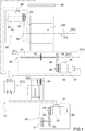
Figure 1 schematically illustrates a machine for correctly rewinding a wire on a spool; said machine being suitable to implement the method which is the main object of the present invention; and -
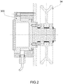
Figure 2 illustrates some details of the machine inFigure 1 on an enlarged scale. - In
Figure 1 ,number 10 denotes, as a whole, a machine for winding a wire on aspool 100, on which the method according to the invention can be implemented. - The
machine 10 comprises the following devices, placed in-line: - (a) a
feeding device 20 of a wire (not shown) to be wound around thespool 100; saidfeeding device 20 comprises, in a known manner, a pullingring 21 made to rotate by a synchronous electric motor 22 (for example, a brushless motor) by means of a pair ofpulleys belt 25; the synchronouselectric motor 22 is connected to arelative encoder 26, and it is controlled by anelectronic board 27; - (b) an assembly comprising a load cell 300 (
Figure 2 ), to which a spindle is attached, on which awire transmission pulley 34 is rotatably mounted; - (c) a
wire dispensing device 40 comprising aworm screw 41 to control the translation of apulley 42 of the wire dispensing device along an axis (X1) and following one of the two directions defined by the arrows (F1), (F2); theworm screw 41 is made to rotate by a synchronous electric motor 43 (for example, a brushless motor) by means of a pair ofpulleys belt 46; the synchronouselectric motor 43 is connected to arelative encoder 47, and it is controlled by anelectronic board 48; - (d) a
spool assembly 50, comprising saidspool 100, on which the wire (not shown) is wound so as to form a skein of wire (not shown); thespool assembly 50 also includes a respective synchronouselectric motor 51, which makes thespool 100 rotate (around an axis (X2) - arrow (R)) by means of a pair ofpulleys belt 54; the synchronouselectric motor 51 is connected to a correspondingencoder 55 and is controlled by anelectronic board 56; and - (e) a
sensor 60 suitable to read the position of thespool 100 and the configuration of its skein containment flanges; in particular, preferably, but not necessarily, thesensor 60 is not mounted on thewire dispensing device 40. - Incidentally, it should be said that each
electronic board respective encoder respective encoder - According to a preferred embodiment of the invention, a DC bus architecture is used.
- However, using a more complex construction, the same operation could be obtained with DC motors and AC/DC converters and with AC motors and AC/AC converters.
- The electronic boards, 27 48, 56, a
load cell 300 and thesensor 60 controlling the spool are connected electronically to an electronic control unit (CC), which may or may not be built into themachine 10, that manages all functions for controlling and operating the components of themachine 10. - The method according to the present invention comprises the following steps:
- (f1) setting the main geometrical data of the spool on an operator panel of the electronic control unit (by means of dedicated formulas or by means of manually entered data);
- (f2) loading a spool on the machine;
- (f3) acquiring the position of the spool flanges by means of said sensor;
- (f4) calculating the actual spool position and comparing it with the "spool data" set in advance in the electronic control unit in order to check whether the spool loading was successful and whether the spool is consistent with that expected;
- (f5) continuing with the process if the check is positive; or stopping the process and reporting the problem by means of an alarm signal;
- (f6) binding the wire to the spool; an operator starts production by activating a specific command;
- (f7) reading the starting measure of the wire pulling action according to the construction and geometrical shape of the support/load cell assembly;
- (f8) calculating the servodiameter according to the spool data, the production data and the reading of the pulling measure; and
- (f9) calculating the speed of the spool motor according to the servodiameter, with the aim of maintaining a constant winding pulling action.
- The present method is characterized in that it comprises a further step for calculating the angular speed of a motor displacing the wire dispensing device according to the wire winding pitch and according to the pulling error, detected in relation to a given pre-set set-point and to a tolerance value, in order to determine the presence of a possible "valley error", or of a possible "peak error". The method is also characterized in that, if a "valley error" or a "peak error" is detected during the spool winding, the control device decides whether to slow down or to increase the speed of the wire dispensing device with the aim of filling the valley or of skipping the peak.
- The main advantage of the method according to the present invention lies in its reliability. Moreover, to implement the present method, all that is required is a winding machine that envisages the use of a small number of sensors. Furthermore, with the present solution the winding machine operator does not have to continuously/frequently correct the reverse position of the wire dispenser device, thereby reducing the amount of time the operator has to spend on a single machine. In this way, each individual operator can manage a larger number of winding machines.
Claims (5)
- Method for implementing a correct winding of a wire on a spool (100), the method comprising the following steps:(f1) setting the main geometrical data of the spool (100) on an operation panel of an electronic control unit (CC) ;(f2) loading a spool (100) on the machine;(f3) acquiring the position of the spool (100) flanges by means of a sensor (60);(f4) calculating the actual spool (100) position and comparing it with said main geometrical data of the spool (100) set in advance in said electronic control unit (CC) in order to check whether the spool (100) loading was successful and whether the spool (100) is consistent with that expected;(f5) continuing with the process if the check is positive; or stopping the process and reporting the problem by means of an alarm signal;(f6) binding the wire to the spool (100); an operator starts the production by activating a specific command;(f7) reading the starting measure of the wire pulling action according to the construction and geometrical shape of an assembly comprising a load cell (300);(f8) calculating the servodiameter according to the spool (100) data, the production data and the reading of the pulling measure; and(f9) calculating the speed of the spool motor (51) according to the servodiameter with the aim of maintaining a constant winding pulling action;said method characterized in that it comprises a further step for calculating the angular speed of a motor (43) displacing the wire dispensing device (40) according to the wire winding pitch and according to the pulling error, detected in relation to a given pre-set set-point and to a tolerance value, in order to determine the presence of a possible "valley error", or of a possible "peak error"; and in that if during the spool winding a "valley error" or a "peak error" is detected, said electronic control unit (CC) decides whether to slow down or to increase the speed of the wire dispensing device (40) with the aim of filling the valley or skipping the peak.
- Method, according to claim 1, characterized in that it comprises a further step wherein the reversal position of the wire dispensing device (40) is calculated according to the spool (100) flange position detected by said sensor (60) during the spool (100) loading, and according to an error of said assembly comprising a load cell (300) able to measure the pulling action of the wire; said error being used to determine the presence of a valley or of a peak, and therefore to increase or to reduce the reversal position.
- Method, according to anyone of the preceding claims, characterized in that it comprises a further step for calculating the length of the wire wound as a skein on the spool (100).
- Method, according to anyone of the preceding claims, characterized in that it comprises at least a step of cable data transmission, or wireless transmission, to remote units for controlling the machine and/or the production line.
- Machine for winding a wire on a spool (100), characterized in that it can implement a method for a correct winding of a wire on a spool (100) according to anyone of claims 1-4.
Applications Claiming Priority (2)
| Application Number | Priority Date | Filing Date | Title |
|---|---|---|---|
| ITBO20140521 | 2014-09-23 | ||
| PCT/IB2015/057339 WO2016046769A1 (en) | 2014-09-23 | 2015-09-23 | Method for implementing a correct winding of a wire on a spool |
Publications (2)
| Publication Number | Publication Date |
|---|---|
| EP3197809A1 EP3197809A1 (en) | 2017-08-02 |
| EP3197809B1 true EP3197809B1 (en) | 2019-06-26 |
Family
ID=52130561
Family Applications (1)
| Application Number | Title | Priority Date | Filing Date |
|---|---|---|---|
| EP15790265.1A Active EP3197809B1 (en) | 2014-09-23 | 2015-09-23 | Method for implementing a correct winding of a wire on a spool |
Country Status (7)
| Country | Link |
|---|---|
| US (1) | US10569987B2 (en) |
| EP (1) | EP3197809B1 (en) |
| JP (1) | JP6695330B2 (en) |
| KR (1) | KR20170086020A (en) |
| CN (1) | CN107108147A (en) |
| ES (1) | ES2740699T3 (en) |
| WO (1) | WO2016046769A1 (en) |
Families Citing this family (3)
| Publication number | Priority date | Publication date | Assignee | Title |
|---|---|---|---|---|
| WO2015151073A1 (en) * | 2014-04-03 | 2015-10-08 | Samp S.P.A. Con Unico Socio | Method for implementing a correct winding of a wire on a spool |
| DE102017006083A1 (en) * | 2017-06-28 | 2019-01-03 | Audi Ag | Method and winding machine for automatically producing a coil winding taking into account the wire diameter |
| CN113443519B (en) * | 2021-08-30 | 2021-11-16 | 成都辰迈科技有限公司 | Cable length metering equipment and method based on self-adaptive function |
Family Cites Families (13)
| Publication number | Priority date | Publication date | Assignee | Title |
|---|---|---|---|---|
| US4133035A (en) * | 1977-08-16 | 1979-01-02 | Bethlehem Steel Corporation | Selectable coiling control method and apparatus |
| JPH01203174A (en) * | 1987-10-20 | 1989-08-15 | Furukawa Electric Co Ltd:The | Winding method of linear member |
| JP2571120B2 (en) | 1989-02-16 | 1997-01-16 | 三菱電線工業株式会社 | Wire winding method |
| DE19645992A1 (en) | 1996-11-07 | 1998-05-14 | Henrich Gmbh | Control system for applying string type material on spool |
| KR100582309B1 (en) | 1998-12-29 | 2006-05-22 | 코닝 인코포레이티드 | System and methods for automatically adjusting turnaround position in spool winders |
| JP2003341934A (en) * | 2002-05-28 | 2003-12-03 | Sumitomo Electric Ind Ltd | Wire takeup method and device |
| AU2003297256A1 (en) | 2002-09-16 | 2004-04-30 | Berkeley Process Control, Inc. | Automatic spool package edge quality assessment and correction algorithm for winding applications |
| JP4349982B2 (en) * | 2004-06-24 | 2009-10-21 | 株式会社フジクラ | Wire rod winding method and apparatus |
| JP2007210752A (en) * | 2006-02-09 | 2007-08-23 | Sumitomo Electric Ind Ltd | Wire winding method |
| DE102006018428B8 (en) | 2006-04-20 | 2015-12-17 | Maschinenfabrik Niehoff Gmbh & Co. Kg | Method and device for laying elongated winding material |
| JP2012144323A (en) * | 2011-01-11 | 2012-08-02 | Tmt Machinery Inc | Spun yarn winding device and spun yarn winding facility |
| DE102011015802A1 (en) | 2011-04-01 | 2012-10-04 | Oerlikon Textile Gmbh & Co. Kg | Method and device for winding an edge sleeve |
| US9809416B1 (en) * | 2012-12-15 | 2017-11-07 | Southwire Company, Llc | Cable reel length calculator |
-
2015
- 2015-09-23 KR KR1020177008052A patent/KR20170086020A/en unknown
- 2015-09-23 JP JP2017515964A patent/JP6695330B2/en active Active
- 2015-09-23 CN CN201580051222.9A patent/CN107108147A/en active Pending
- 2015-09-23 US US15/513,092 patent/US10569987B2/en active Active
- 2015-09-23 ES ES15790265T patent/ES2740699T3/en active Active
- 2015-09-23 EP EP15790265.1A patent/EP3197809B1/en active Active
- 2015-09-23 WO PCT/IB2015/057339 patent/WO2016046769A1/en active Application Filing
Non-Patent Citations (1)
| Title |
|---|
| None * |
Also Published As
| Publication number | Publication date |
|---|---|
| WO2016046769A1 (en) | 2016-03-31 |
| US10569987B2 (en) | 2020-02-25 |
| EP3197809A1 (en) | 2017-08-02 |
| JP6695330B2 (en) | 2020-05-20 |
| KR20170086020A (en) | 2017-07-25 |
| US20170247219A1 (en) | 2017-08-31 |
| JP2017532268A (en) | 2017-11-02 |
| CN107108147A (en) | 2017-08-29 |
| ES2740699T3 (en) | 2020-02-06 |
Similar Documents
| Publication | Publication Date | Title |
|---|---|---|
| US7370823B2 (en) | Method and device for laying of elongated winding material | |
| EP3197809B1 (en) | Method for implementing a correct winding of a wire on a spool | |
| US10011456B2 (en) | Method for implementing a correct winding of a wire on a spool | |
| JP6005797B1 (en) | Wire winding device | |
| CN104310123A (en) | Winding system for textile machinery | |
| JP2017532268A5 (en) | ||
| CN106059218B (en) | The coiling of coil winding machine and insulating tape wrapping continuous synchronization operational method and device | |
| CN103901853A (en) | Single-spindle single control system applied to air covered yarn machine and control method | |
| CN108698781B (en) | Management method for a coiler device and corresponding apparatus | |
| CN113753781B (en) | Self-adaptive multi-redundancy cable arranging system and control method | |
| CN216182975U (en) | Detection device of steel wire ring spiral cloth wrapping machine | |
| CN107416583B (en) | Control system and control method of special-shaped steel strip rewinder | |
| WO2008125965A2 (en) | Method for winding a filiform element into a coil and winding machine implementing said method. | |
| CN204847560U (en) | A take -up device for coiling strip of cohesive material system | |
| KR20140079653A (en) | Winding machine for low strenght metal wire | |
| US10442656B2 (en) | Wire-winding machine and method for winding a reel with juxtaposed coils | |
| CN105366428A (en) | Method and device for avoiding pattern windings during the winding of a cross-wound bobbin | |
| CA2374458A1 (en) | Device for formation of skeined sections on thin metallic wires | |
| CN104670997A (en) | Method for changing position folding line of movable rail seat on winch screw into straight line | |
| CN117228431A (en) | Cable take-up device | |
| ITMI951298A1 (en) | PROCEDURE AND DEVICE TO AVOID IRREGULAR WINDINGS | |
| CN102649519A (en) | Optical fiber winding method | |
| ITVI20090151A1 (en) | METHOD OF WRAPPING OF A FILIFORM ELEMENT IN A REFINED COIL |
Legal Events
| Date | Code | Title | Description |
|---|---|---|---|
| STAA | Information on the status of an ep patent application or granted ep patent |
Free format text: STATUS: THE INTERNATIONAL PUBLICATION HAS BEEN MADE |
|
| PUAI | Public reference made under article 153(3) epc to a published international application that has entered the european phase |
Free format text: ORIGINAL CODE: 0009012 |
|
| STAA | Information on the status of an ep patent application or granted ep patent |
Free format text: STATUS: REQUEST FOR EXAMINATION WAS MADE |
|
| 17P | Request for examination filed |
Effective date: 20170314 |
|
| AK | Designated contracting states |
Kind code of ref document: A1 Designated state(s): AL AT BE BG CH CY CZ DE DK EE ES FI FR GB GR HR HU IE IS IT LI LT LU LV MC MK MT NL NO PL PT RO RS SE SI SK SM TR |
|
| AX | Request for extension of the european patent |
Extension state: BA ME |
|
| DAV | Request for validation of the european patent (deleted) | ||
| DAX | Request for extension of the european patent (deleted) | ||
| GRAP | Despatch of communication of intention to grant a patent |
Free format text: ORIGINAL CODE: EPIDOSNIGR1 |
|
| STAA | Information on the status of an ep patent application or granted ep patent |
Free format text: STATUS: GRANT OF PATENT IS INTENDED |
|
| INTG | Intention to grant announced |
Effective date: 20190118 |
|
| GRAS | Grant fee paid |
Free format text: ORIGINAL CODE: EPIDOSNIGR3 |
|
| GRAA | (expected) grant |
Free format text: ORIGINAL CODE: 0009210 |
|
| STAA | Information on the status of an ep patent application or granted ep patent |
Free format text: STATUS: THE PATENT HAS BEEN GRANTED |
|
| AK | Designated contracting states |
Kind code of ref document: B1 Designated state(s): AL AT BE BG CH CY CZ DE DK EE ES FI FR GB GR HR HU IE IS IT LI LT LU LV MC MK MT NL NO PL PT RO RS SE SI SK SM TR |
|
| REG | Reference to a national code |
Ref country code: GB Ref legal event code: FG4D |
|
| REG | Reference to a national code |
Ref country code: CH Ref legal event code: EP |
|
| REG | Reference to a national code |
Ref country code: AT Ref legal event code: REF Ref document number: 1148051 Country of ref document: AT Kind code of ref document: T Effective date: 20190715 |
|
| REG | Reference to a national code |
Ref country code: IE Ref legal event code: FG4D |
|
| REG | Reference to a national code |
Ref country code: DE Ref legal event code: R096 Ref document number: 602015032797 Country of ref document: DE |
|
| REG | Reference to a national code |
Ref country code: CH Ref legal event code: NV Representative=s name: HEPP WENGER RYFFEL AG, CH |
|
| REG | Reference to a national code |
Ref country code: NL Ref legal event code: MP Effective date: 20190626 |
|
| PG25 | Lapsed in a contracting state [announced via postgrant information from national office to epo] |
Ref country code: AL Free format text: LAPSE BECAUSE OF FAILURE TO SUBMIT A TRANSLATION OF THE DESCRIPTION OR TO PAY THE FEE WITHIN THE PRESCRIBED TIME-LIMIT Effective date: 20190626 Ref country code: NO Free format text: LAPSE BECAUSE OF FAILURE TO SUBMIT A TRANSLATION OF THE DESCRIPTION OR TO PAY THE FEE WITHIN THE PRESCRIBED TIME-LIMIT Effective date: 20190926 Ref country code: HR Free format text: LAPSE BECAUSE OF FAILURE TO SUBMIT A TRANSLATION OF THE DESCRIPTION OR TO PAY THE FEE WITHIN THE PRESCRIBED TIME-LIMIT Effective date: 20190626 Ref country code: SE Free format text: LAPSE BECAUSE OF FAILURE TO SUBMIT A TRANSLATION OF THE DESCRIPTION OR TO PAY THE FEE WITHIN THE PRESCRIBED TIME-LIMIT Effective date: 20190626 Ref country code: LT Free format text: LAPSE BECAUSE OF FAILURE TO SUBMIT A TRANSLATION OF THE DESCRIPTION OR TO PAY THE FEE WITHIN THE PRESCRIBED TIME-LIMIT Effective date: 20190626 |
|
| REG | Reference to a national code |
Ref country code: LT Ref legal event code: MG4D |
|
| PG25 | Lapsed in a contracting state [announced via postgrant information from national office to epo] |
Ref country code: LV Free format text: LAPSE BECAUSE OF FAILURE TO SUBMIT A TRANSLATION OF THE DESCRIPTION OR TO PAY THE FEE WITHIN THE PRESCRIBED TIME-LIMIT Effective date: 20190626 Ref country code: BG Free format text: LAPSE BECAUSE OF FAILURE TO SUBMIT A TRANSLATION OF THE DESCRIPTION OR TO PAY THE FEE WITHIN THE PRESCRIBED TIME-LIMIT Effective date: 20190926 Ref country code: RS Free format text: LAPSE BECAUSE OF FAILURE TO SUBMIT A TRANSLATION OF THE DESCRIPTION OR TO PAY THE FEE WITHIN THE PRESCRIBED TIME-LIMIT Effective date: 20190626 Ref country code: GR Free format text: LAPSE BECAUSE OF FAILURE TO SUBMIT A TRANSLATION OF THE DESCRIPTION OR TO PAY THE FEE WITHIN THE PRESCRIBED TIME-LIMIT Effective date: 20190927 |
|
| PG25 | Lapsed in a contracting state [announced via postgrant information from national office to epo] |
Ref country code: PT Free format text: LAPSE BECAUSE OF FAILURE TO SUBMIT A TRANSLATION OF THE DESCRIPTION OR TO PAY THE FEE WITHIN THE PRESCRIBED TIME-LIMIT Effective date: 20191028 Ref country code: SK Free format text: LAPSE BECAUSE OF FAILURE TO SUBMIT A TRANSLATION OF THE DESCRIPTION OR TO PAY THE FEE WITHIN THE PRESCRIBED TIME-LIMIT Effective date: 20190626 Ref country code: EE Free format text: LAPSE BECAUSE OF FAILURE TO SUBMIT A TRANSLATION OF THE DESCRIPTION OR TO PAY THE FEE WITHIN THE PRESCRIBED TIME-LIMIT Effective date: 20190626 Ref country code: RO Free format text: LAPSE BECAUSE OF FAILURE TO SUBMIT A TRANSLATION OF THE DESCRIPTION OR TO PAY THE FEE WITHIN THE PRESCRIBED TIME-LIMIT Effective date: 20190626 Ref country code: CZ Free format text: LAPSE BECAUSE OF FAILURE TO SUBMIT A TRANSLATION OF THE DESCRIPTION OR TO PAY THE FEE WITHIN THE PRESCRIBED TIME-LIMIT Effective date: 20190626 Ref country code: NL Free format text: LAPSE BECAUSE OF FAILURE TO SUBMIT A TRANSLATION OF THE DESCRIPTION OR TO PAY THE FEE WITHIN THE PRESCRIBED TIME-LIMIT Effective date: 20190626 |
|
| REG | Reference to a national code |
Ref country code: ES Ref legal event code: FG2A Ref document number: 2740699 Country of ref document: ES Kind code of ref document: T3 Effective date: 20200206 |
|
| PG25 | Lapsed in a contracting state [announced via postgrant information from national office to epo] |
Ref country code: SM Free format text: LAPSE BECAUSE OF FAILURE TO SUBMIT A TRANSLATION OF THE DESCRIPTION OR TO PAY THE FEE WITHIN THE PRESCRIBED TIME-LIMIT Effective date: 20190626 Ref country code: IS Free format text: LAPSE BECAUSE OF FAILURE TO SUBMIT A TRANSLATION OF THE DESCRIPTION OR TO PAY THE FEE WITHIN THE PRESCRIBED TIME-LIMIT Effective date: 20191026 |
|
| PG25 | Lapsed in a contracting state [announced via postgrant information from national office to epo] |
Ref country code: TR Free format text: LAPSE BECAUSE OF FAILURE TO SUBMIT A TRANSLATION OF THE DESCRIPTION OR TO PAY THE FEE WITHIN THE PRESCRIBED TIME-LIMIT Effective date: 20190626 |
|
| PG25 | Lapsed in a contracting state [announced via postgrant information from national office to epo] |
Ref country code: DK Free format text: LAPSE BECAUSE OF FAILURE TO SUBMIT A TRANSLATION OF THE DESCRIPTION OR TO PAY THE FEE WITHIN THE PRESCRIBED TIME-LIMIT Effective date: 20190626 Ref country code: PL Free format text: LAPSE BECAUSE OF FAILURE TO SUBMIT A TRANSLATION OF THE DESCRIPTION OR TO PAY THE FEE WITHIN THE PRESCRIBED TIME-LIMIT Effective date: 20190626 |
|
| PG25 | Lapsed in a contracting state [announced via postgrant information from national office to epo] |
Ref country code: IS Free format text: LAPSE BECAUSE OF FAILURE TO SUBMIT A TRANSLATION OF THE DESCRIPTION OR TO PAY THE FEE WITHIN THE PRESCRIBED TIME-LIMIT Effective date: 20200224 Ref country code: MC Free format text: LAPSE BECAUSE OF FAILURE TO SUBMIT A TRANSLATION OF THE DESCRIPTION OR TO PAY THE FEE WITHIN THE PRESCRIBED TIME-LIMIT Effective date: 20190626 |
|
| REG | Reference to a national code |
Ref country code: DE Ref legal event code: R097 Ref document number: 602015032797 Country of ref document: DE |
|
| PLBE | No opposition filed within time limit |
Free format text: ORIGINAL CODE: 0009261 |
|
| STAA | Information on the status of an ep patent application or granted ep patent |
Free format text: STATUS: NO OPPOSITION FILED WITHIN TIME LIMIT |
|
| PG2D | Information on lapse in contracting state deleted |
Ref country code: IS |
|
| PG25 | Lapsed in a contracting state [announced via postgrant information from national office to epo] |
Ref country code: IE Free format text: LAPSE BECAUSE OF NON-PAYMENT OF DUE FEES Effective date: 20190923 Ref country code: LU Free format text: LAPSE BECAUSE OF NON-PAYMENT OF DUE FEES Effective date: 20190923 |
|
| REG | Reference to a national code |
Ref country code: BE Ref legal event code: MM Effective date: 20190930 |
|
| 26N | No opposition filed |
Effective date: 20200603 |
|
| REG | Reference to a national code |
Ref country code: AT Ref legal event code: UEP Ref document number: 1148051 Country of ref document: AT Kind code of ref document: T Effective date: 20190626 |
|
| PG25 | Lapsed in a contracting state [announced via postgrant information from national office to epo] |
Ref country code: SI Free format text: LAPSE BECAUSE OF FAILURE TO SUBMIT A TRANSLATION OF THE DESCRIPTION OR TO PAY THE FEE WITHIN THE PRESCRIBED TIME-LIMIT Effective date: 20190626 Ref country code: BE Free format text: LAPSE BECAUSE OF NON-PAYMENT OF DUE FEES Effective date: 20190930 |
|
| GBPC | Gb: european patent ceased through non-payment of renewal fee |
Effective date: 20190926 |
|
| PG25 | Lapsed in a contracting state [announced via postgrant information from national office to epo] |
Ref country code: GB Free format text: LAPSE BECAUSE OF NON-PAYMENT OF DUE FEES Effective date: 20190926 |
|
| PG25 | Lapsed in a contracting state [announced via postgrant information from national office to epo] |
Ref country code: CY Free format text: LAPSE BECAUSE OF FAILURE TO SUBMIT A TRANSLATION OF THE DESCRIPTION OR TO PAY THE FEE WITHIN THE PRESCRIBED TIME-LIMIT Effective date: 20190626 |
|
| PG25 | Lapsed in a contracting state [announced via postgrant information from national office to epo] |
Ref country code: MT Free format text: LAPSE BECAUSE OF FAILURE TO SUBMIT A TRANSLATION OF THE DESCRIPTION OR TO PAY THE FEE WITHIN THE PRESCRIBED TIME-LIMIT Effective date: 20190626 Ref country code: HU Free format text: LAPSE BECAUSE OF FAILURE TO SUBMIT A TRANSLATION OF THE DESCRIPTION OR TO PAY THE FEE WITHIN THE PRESCRIBED TIME-LIMIT; INVALID AB INITIO Effective date: 20150923 |
|
| PG25 | Lapsed in a contracting state [announced via postgrant information from national office to epo] |
Ref country code: MK Free format text: LAPSE BECAUSE OF FAILURE TO SUBMIT A TRANSLATION OF THE DESCRIPTION OR TO PAY THE FEE WITHIN THE PRESCRIBED TIME-LIMIT Effective date: 20190626 |
|
| PGFP | Annual fee paid to national office [announced via postgrant information from national office to epo] |
Ref country code: FI Payment date: 20230926 Year of fee payment: 9 Ref country code: AT Payment date: 20230919 Year of fee payment: 9 |
|
| PGFP | Annual fee paid to national office [announced via postgrant information from national office to epo] |
Ref country code: FR Payment date: 20230926 Year of fee payment: 9 Ref country code: DE Payment date: 20230928 Year of fee payment: 9 |
|
| PGFP | Annual fee paid to national office [announced via postgrant information from national office to epo] |
Ref country code: ES Payment date: 20231017 Year of fee payment: 9 |
|
| PGFP | Annual fee paid to national office [announced via postgrant information from national office to epo] |
Ref country code: IT Payment date: 20230925 Year of fee payment: 9 Ref country code: CH Payment date: 20231001 Year of fee payment: 9 |