EP3197780B1 - Folding machine for folding flaps of a wrapper - Google Patents
Folding machine for folding flaps of a wrapper Download PDFInfo
- Publication number
- EP3197780B1 EP3197780B1 EP15766196.8A EP15766196A EP3197780B1 EP 3197780 B1 EP3197780 B1 EP 3197780B1 EP 15766196 A EP15766196 A EP 15766196A EP 3197780 B1 EP3197780 B1 EP 3197780B1
- Authority
- EP
- European Patent Office
- Prior art keywords
- shuttle
- pusher
- folders
- machine
- package
- Prior art date
- Legal status (The legal status is an assumption and is not a legal conclusion. Google has not performed a legal analysis and makes no representation as to the accuracy of the status listed.)
- Not-in-force
Links
Images


Classifications
-
- B—PERFORMING OPERATIONS; TRANSPORTING
- B65—CONVEYING; PACKING; STORING; HANDLING THIN OR FILAMENTARY MATERIAL
- B65B—MACHINES, APPARATUS OR DEVICES FOR, OR METHODS OF, PACKAGING ARTICLES OR MATERIALS; UNPACKING
- B65B11/00—Wrapping, e.g. partially or wholly enclosing, articles or quantities of material, in strips, sheets or blanks, of flexible material
- B65B11/48—Enclosing articles, or quantities of material, by folding a wrapper, e.g. a pocketed wrapper, and securing its opposed free margins to enclose contents
-
- B—PERFORMING OPERATIONS; TRANSPORTING
- B65—CONVEYING; PACKING; STORING; HANDLING THIN OR FILAMENTARY MATERIAL
- B65B—MACHINES, APPARATUS OR DEVICES FOR, OR METHODS OF, PACKAGING ARTICLES OR MATERIALS; UNPACKING
- B65B19/00—Packaging rod-shaped or tubular articles susceptible to damage by abrasion or pressure, e.g. cigarettes, cigars, macaroni, spaghetti, drinking straws or welding electrodes
- B65B19/02—Packaging cigarettes
- B65B19/22—Wrapping the cigarettes; Packaging the cigarettes in containers formed by folding wrapping material around formers
- B65B19/223—Wrapping the cigarettes; Packaging the cigarettes in containers formed by folding wrapping material around formers in a curved path; in a combination of straight and curved paths, e.g. on rotary tables or other endless conveyors
- B65B19/226—Wrapping the cigarettes; Packaging the cigarettes in containers formed by folding wrapping material around formers in a curved path; in a combination of straight and curved paths, e.g. on rotary tables or other endless conveyors using endless conveyors having pockets, each pocket being provided with separate members, e.g. folders
-
- B—PERFORMING OPERATIONS; TRANSPORTING
- B65—CONVEYING; PACKING; STORING; HANDLING THIN OR FILAMENTARY MATERIAL
- B65B—MACHINES, APPARATUS OR DEVICES FOR, OR METHODS OF, PACKAGING ARTICLES OR MATERIALS; UNPACKING
- B65B19/00—Packaging rod-shaped or tubular articles susceptible to damage by abrasion or pressure, e.g. cigarettes, cigars, macaroni, spaghetti, drinking straws or welding electrodes
- B65B19/02—Packaging cigarettes
- B65B19/025—Packaging cigarettes in webs of flexible sheet material
-
- B—PERFORMING OPERATIONS; TRANSPORTING
- B65—CONVEYING; PACKING; STORING; HANDLING THIN OR FILAMENTARY MATERIAL
- B65B—MACHINES, APPARATUS OR DEVICES FOR, OR METHODS OF, PACKAGING ARTICLES OR MATERIALS; UNPACKING
- B65B11/00—Wrapping, e.g. partially or wholly enclosing, articles or quantities of material, in strips, sheets or blanks, of flexible material
- B65B11/06—Wrapping articles, or quantities of material, by conveying wrapper and contents in common defined paths
- B65B11/08—Wrapping articles, or quantities of material, by conveying wrapper and contents in common defined paths in a single straight path
- B65B11/16—Wrapping articles, or quantities of material, by conveying wrapper and contents in common defined paths in a single straight path to fold the wrappers in channel form about contents and then to close the ends of the channel by folding and finally the mouth of the channel by folding or twisting
-
- B—PERFORMING OPERATIONS; TRANSPORTING
- B65—CONVEYING; PACKING; STORING; HANDLING THIN OR FILAMENTARY MATERIAL
- B65B—MACHINES, APPARATUS OR DEVICES FOR, OR METHODS OF, PACKAGING ARTICLES OR MATERIALS; UNPACKING
- B65B19/00—Packaging rod-shaped or tubular articles susceptible to damage by abrasion or pressure, e.g. cigarettes, cigars, macaroni, spaghetti, drinking straws or welding electrodes
- B65B19/02—Packaging cigarettes
- B65B19/22—Wrapping the cigarettes; Packaging the cigarettes in containers formed by folding wrapping material around formers
- B65B19/221—Wrapping the cigarettes; Packaging the cigarettes in containers formed by folding wrapping material around formers in one or more straight paths
-
- B—PERFORMING OPERATIONS; TRANSPORTING
- B65—CONVEYING; PACKING; STORING; HANDLING THIN OR FILAMENTARY MATERIAL
- B65B—MACHINES, APPARATUS OR DEVICES FOR, OR METHODS OF, PACKAGING ARTICLES OR MATERIALS; UNPACKING
- B65B35/00—Supplying, feeding, arranging or orientating articles to be packaged
- B65B35/30—Arranging and feeding articles in groups
- B65B35/36—Arranging and feeding articles in groups by grippers
-
- B—PERFORMING OPERATIONS; TRANSPORTING
- B65—CONVEYING; PACKING; STORING; HANDLING THIN OR FILAMENTARY MATERIAL
- B65B—MACHINES, APPARATUS OR DEVICES FOR, OR METHODS OF, PACKAGING ARTICLES OR MATERIALS; UNPACKING
- B65B35/00—Supplying, feeding, arranging or orientating articles to be packaged
- B65B35/30—Arranging and feeding articles in groups
- B65B35/40—Arranging and feeding articles in groups by reciprocating or oscillatory pushers
-
- B—PERFORMING OPERATIONS; TRANSPORTING
- B65—CONVEYING; PACKING; STORING; HANDLING THIN OR FILAMENTARY MATERIAL
- B65B—MACHINES, APPARATUS OR DEVICES FOR, OR METHODS OF, PACKAGING ARTICLES OR MATERIALS; UNPACKING
- B65B49/00—Devices for folding or bending wrappers around contents
- B65B49/08—Reciprocating or oscillating folders
-
- B—PERFORMING OPERATIONS; TRANSPORTING
- B65—CONVEYING; PACKING; STORING; HANDLING THIN OR FILAMENTARY MATERIAL
- B65B—MACHINES, APPARATUS OR DEVICES FOR, OR METHODS OF, PACKAGING ARTICLES OR MATERIALS; UNPACKING
- B65B49/00—Devices for folding or bending wrappers around contents
- B65B49/14—Folders forming part of, or attached to, conveyors for partially-wrapped articles
-
- B—PERFORMING OPERATIONS; TRANSPORTING
- B65—CONVEYING; PACKING; STORING; HANDLING THIN OR FILAMENTARY MATERIAL
- B65B—MACHINES, APPARATUS OR DEVICES FOR, OR METHODS OF, PACKAGING ARTICLES OR MATERIALS; UNPACKING
- B65B19/00—Packaging rod-shaped or tubular articles susceptible to damage by abrasion or pressure, e.g. cigarettes, cigars, macaroni, spaghetti, drinking straws or welding electrodes
- B65B19/02—Packaging cigarettes
- B65B19/22—Wrapping the cigarettes; Packaging the cigarettes in containers formed by folding wrapping material around formers
- B65B19/24—Wrapping the cigarettes; Packaging the cigarettes in containers formed by folding wrapping material around formers using hollow mandrels through which groups of cigarettes are fed
Definitions
- This invention relates to a machine for folding an end of a wrapper.
- Overwrapping is commonly used in an industrial wrapping process; examples include wrapping foil around a bundle of cigarettes or creating a cellophane wrapper around a package.
- a leading end of a package is passed through a web of wrapping material.
- Ploughs or folders are provided to fold the wrapping material along the sides of the package. Once the side folds have been completed a cuboidal package will be covered on five of its six surfaces.
- a challenge in the overwrapping process is how to create folds on the sixth surface, which is the trailing end.
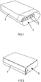
- Figure 1 shows a bundle of cigarettes 2 that have been through the beginning of an overwrapping process so that they are partially wrapped in a metal-laminated wrapper 4.
- the wrapper covers five of the six surfaces of the bundle and only the trailing end 6 has yet to be folded.
- Figure 2 shows the same bundle of cigarettes in which the folding process has been completed on the trailing end 6.
- An object of this invention is to produce a machine that will form these folds on the trailing end 6.
- GB 1525715 A discloses a process of forming and filling a flip top packet using a turret rotatable about a vertical axis and having upwardly and radially outwardly open pockets.
- a punch plate pushes a blank into a pocket such that the rear wall of the blank lies on the bottom of the pocket, the end wall, front wall and lateral flaps are folded into an upright position at the radial inner end of the pocket, and lateral flaps are folded upwardly from the rear wall.
- the packet is passed around a rotary turret arrangement to allow the glue on the packet to set.
- An object of the invention is to provide a simpler and more cost effective machine for folding the unwrapped trailing end of a partially wrapped package. Another object of the invention is to facilitate improved speed of wrapping.
- the second pusher is configured to contact an area of the trailing end face of the wrapped package that has not been in contact with any of the plurality of folders. In this way the folders can fold flaps on the trailing end of the package and the second pusher can eject the package without colliding with any of the folders. This allows for high speed production.
- the second pusher may also prevent the flaps from unfolding after the package has moved away from the folders.
- a slot is provided in one of the folders, or between folders, and the second pusher is moveable within the slot to eject the wrapped package from the pocket.
- the second pusher can act on the trailing end of the wrapped package and drive it out of the pocket.
- the slot is preferably provided in a bottom folder and along a lower surface of the shuttle. In this way the second pusher can be provided on a conveyer belt below the shuttle.
- the machine preferably includes the first pusher configured to introduce the partially wrapped package into the pocket of the shuttle.
- the first pusher is preferably configured to act on the unwrapped trailing end of the partially wrapped package.
- the first pusher is arranged to push the package through a web of wrapping material, such as paper of metal-laminated paper, at an earlier stage of the wrapping process. In this way an overwrap may be created on the package and the shuttle is designed to fold flaps over the trailing end face.
- At least one of the folders may comprise projections which complement the shape of corresponding notches on the second pusher.
- the projections may increase the effectiveness of the folder by increasing its lever moment on a relevant flap. In other words, the projections improve the reach of the folder away from the pivoting axis of a flap.
- the projections pass through the notches when the second pusher moves relative to the folder so that the second pusher can take control of movement of the package.
- the second pusher It is generally desirable for the second pusher to contact the end face of the package across a significant proportion of its width and length. This allows the second pusher to hold the flaps of the folded wrapper in place when the package has been moved away from the folders.
- At least one of the folders may comprise notches which complement the shape of corresponding projections on the second pusher.
- the projections on the second pusher may advantageously hold the folded flaps in place while the package is being ejected from the pocket.
- the second pusher may have a structure like a television aerial or a tree, with a number of projections or branches, emanating from a central body, and notches between the projections.
- Two of the folders may be arranged along opposing edges of the package and each of these folders may comprise projections which are respectively offset from one another along the length of the pocket.
- the second pusher can include notches and projections that complement the shape of the projections on the folders.
- the shuttle preferably comprises top, bottom and side folders configured to fold flaps of the partially unwrapped package along respective edges of the end face.
- the shuttle comprises at least four integrated folders. This design reduces the complexity and cost of the machine in comparison to conventional designs.
- "top”, “bottom” and “side” have been used as convenient labels for respective sides of the package; these labels are not limited to any particular reference frame since it would be possible to fold the package in any convenient orientation.
- the trailing end face is substantially rectangular and the package is a cuboid.
- the wrapped bundle may have a substantially rectangular end face, even though the unwrapped bundle is formed by a plurality of cylindrical rods.
- the shuttle may comprise two bottom folders, movable between an open position and a closed position, and a gap is preferably provided between the bottom folders in the closed position so that the second pusher can move in the gap in order to eject the wrapped package from the shuttle.
- the folders are preferably operated in a sequence which is: side folders, bottom folder, top folder. It has been found that this creates a neat fold on the trailing end face of the package, with top flap folded so that it overlaps the bottom flap.
- the machine preferably includes a shuttle drive mechanism configured to reciprocate the shuttle relative to a fixed base.
- the shuttle can collect the partially wrapped package from the first pusher and complete the folds.
- the package can then be ejected from the shuttle and passed on to the next stage using the second pusher.
- At least one of the side folders may include a track follower and the fixed base may comprise a track.
- the track follower may be configured to move relative to the track when the shuttle is reciprocated by the shuttle drive mechanism so that the at least one side folder can move in order to fold a side flap on the partially wrapped package.
- the track and the track follower are arranged so that the movement of the side flap occurs near a mid-point of the reciprocating movement of the shuttle. In a typical sinusoidal reciprocation the speed of the shuttle is maximal at the mid-point and it is desirable to activate the side folders at this point since it can create a snappy folding action.
- the machine may also comprise a top folder drive mechanism configured to reciprocate the top folder relative to the fixed base
- a top folder drive mechanism configured to reciprocate the top folder relative to the fixed base
- the top folder drive mechanism is arranged out of phase with the shuttle drive mechanism.
- the top folder drive mechanism may be designed to move the top folder at maximum speed while the shuttle is stationary, at the end of its reciprocating movement. In this way it is possible to provide rapid movement of the top folder, even when the shuttle is stationary, or nearly stationary. This may be desirable because it allows formation of an effective top fold just before the package is ejected from the shuttle.
- the top folder drive mechanism may reciprocate at some integer multiple of the frequency of the shuttle drive mechanism. In a preferred embodiment the top folder drive mechanism reciprocates at twice the frequency of the shuttle drive mechanism.
- a bottom folder drive mechanism is also provided, which runs out of phase with the shuttle drive mechanism.
- the bottom folder drive mechanism may lead the top folder drive mechanism slightly so that the bottom flap is folded before the top flap. This may be achieved by mounting slightly offset eccentric wheels for the bottom and top folder drive mechanisms on a common drive shaft.
- the shuttle may comprise a gripper configured to grip the partially wrapped package when it is received in the pocket and to release the wrapped package so that it can be ejected by the second pusher.
- the shuttle drive mechanism may include a cam and the gripper may include a cam follower so that a relative movement of the cam and the cam follower is configured to drive the gripper from a releasing position towards a gripping position. Equally, movement of the cam relative to the cam follower may be arranged to drive the gripper from its gripping position towards its releasing position. In this way the drive mechanism for the gripper can be linked to the drive mechanism for the shuttle. This can ensure synchronisation between the shuttle and the gripper which allows increased speed of operation. In addition, this reduces the complexity of the design since there is no need for any separate drive mechanism for the gripper.
- the machine may be arranged to wrap a package such as a bundle of cigarettes in metal-laminated wrapping paper. However, the machine may also be arranged to wrap other types of package in other materials, including cellophane.
- Method features may be provided as corresponding apparatus features and vice-versa.
- FIGS. 3 to 11 depict aspects of a machine 8 for wrapping a bundle of cigarettes in metal-laminated paper.
- a bundle of twenty cigarettes are wrapped, and these cigarettes are generally arranged in three layers with seven, six and seven rods respectively.
- An overwrapping apparatus (not shown) is provided for pushing a leading end of the bundle through a web of wrapping paper and forming side folds on the bundle.
- This partially wrapped bundle has an unwrapped trailing end and it is conveyed towards the machine 8.
- a pusher 17 on a conveyer belt 21 is arranged to act on the unwrapped trailing end of the bundle so that it is received in the machine through a channel 10.
- the channel 10 includes a slot 12 in a bottom surface.
- the pusher 17 is arranged to extend through the slot 12 so that it can push the unwrapped trailing end of the package along a direction of travel.
- the slot 12 is arranged off-centre in the channel 10 such that it is provided between cigarettes in the bottom layer of the bundle. Generally the slot 12 is provided between the third and fourth cigarettes on the bottom layer of the bundle. In this way the bundle can remain tightly packed because none of the cigarettes in the bundle can drop downwards into the slot 12.
- the machine 8 comprises a shuttle 14 configured to receive the partially wrapped bundle when it is pushed through the channel 10 by the pusher 17. Specifically, the partially wrapped bundle is received in a pocket 16 of the shuttle 14.
- the shuttle 14 also includes a gripper 19 which is moveable in order to reduce the height of the pocket 16 to grip the partially wrapped bundle. The mechanism is timed so that the gripper 19 moves downwardly just as the partially wrapped bundle is inserted into the pocket 16 by the pusher 17. At this point the partially wrapped bundle is securely gripped by the shuttle 14 which then accelerates away from the pusher 17 so that the trailing end can be folded.
- the shuttle 14 comprises runners 26 mounted on stationary rails 24 in the machine 8.
- a shuttle driving mechanism includes a rotor 30 and an arm 32 for moving the runners 26 back-and-forth along the rails 24. In this way the shuttle 14 can be reciprocated along a horizontal axis 28.
- the reciprocating movement is arranged so that the partially wrapped bundle of cigarettes is pushed into the pocket 16 by the pusher when the shuttle 14 is stationary at one extreme end of its reciprocal motion.
- the trailing end of the bundle is then wrapped while the shuttle 14 moves towards the other extreme end of its reciprocal motion and the wrapped bundle is ejected from the pocket 16 by a pusher 94.
- a plurality of pushers 94 are provided at spaced intervals on a conveyer belt 96 which runs in a loop below the shuttle 14.
- Each pusher 94 comprises a base 98 which is fixed to the conveyer belt 96 and a central stem 100 that extends away from the belt 96.
- a branched contact member including upper projections 102 and upper notches 104, and lower projections 106 and lower notches 108.
- the upper projections 102 are offset from the lower projections 106 along the width of the pusher.
- the endmost upper projections 110 are turned outwards to the sides; these endmost projections 110 help to hold folded side flaps in place once the package has moved away from the side folders 20.
- the reciprocating shuttle 14 comprises a top folder 18, two side folders 20 and two bottom folders 22. All of the folders 18, 20, 22 are integrated with the shuttle 14 so that they move with it on the runners 26. Each of the folders has an open position to allow the partially wrapped package to be inserted into the pocket 16.
- the folders 18, 20, 22 are all moveable from their open position to a closed position in order to fold a flap on the trailing end face of the bundle of cigarettes. This allows a neat folded package to be produced, as shown in Figure 2 .
- the top folder 18 and both of the bottom folders 22 have a crenellated shape with projections and notches.
- the projections on the top folder 18 are offset from those on the bottom folders 22 across the width of the pocket 6.
- the projections on the folders satisfy competing interests. Firstly, the projections facilitate a large lever moment on a flap so that the fold is executed neatly, and secondly the notches allow a second pusher 94 to act across a large span on the trailing edge of the wrapped bundle, which is useful for holding the folded flaps in place.
- the base 34 of the pocket 16 is in two portions with a slot 36 in the middle.
- a gap 38 is provided between the bottom folders 22 in their closed configuration which is aligned with the slot 36.
- the slot 36 is provided so that the pusher 94 can push the trailing end of the wrapped bundle of cigarettes out of the pocket 16 without colliding with any other components of the shuttle 14.
- one of the pushers 94 on the conveyer belt 96 is arranged to accelerate towards the wrapped trailing end of a bundle as the reciprocating shuttle 14 slows down, towards an extreme end of its reciprocating movement.
- the top and bottom folders 18, 22 are in their closed configurations and the stem 100 of the pusher 94 passes between the gap 38 in the bottom folders 22.
- the upper projections 102 of the pusher 94 pass through notches in the upper folder 18 and the lower projections 106 of the pusher 94 pass through notches in the bottom folders 22.
- the pusher 94 contacts the folded trailing end face of the bundle and moves it away from the top and bottom folders 18, 22.
- the aerial-like shape of the branched contact member holds the folded flaps in place on the trailing end face.
- the stem 100 then passes through the slot 36 in the bottom of the pocket 16 so that the wrapped bundle can be ejected and moved on to the next phase in the wrapping process.
- the side folders 20 are biased towards their open position, and they are pivotal with respect to the main body of the shuttle 14 about respective pins 42.
- Respective track followers 40 are provided as roller bearings for following a pair of parallel fixed tracks 74 on the machine 8.
- the track 74 is shaped with two flat sections 76, 78 that are parallel to the rails 24 on which the shuttle 14 reciprocates, and a bulge 80.
- the bulge 80 is arranged so that the track follower 40 causes the side folders 20 to create folds towards the middle of the reciprocating movement of the shuttle 14. This improves control over the movement of the side folders 20 so that an effective fold can be created.
- the bulge 80 causes the side folders 20 to tuck the side folds in and then to move back to their open position so that they do not collide with the top and bottom folders 18, 22 which are operated subsequently.
- a drive mechanism 50 is provided for the top and bottom folders 18, 22, which is separate to the drive mechanism 30, 32 for the shuttle 14.
- the drive mechanism 50 includes a drive shaft 52 and an eccentric wheel 54 which drives the top folder 18.
- Two eccentric wheels 56 are also provided to drive the respective bottom folders 22.
- the eccentric wheel 54 for the top folder 18 is connected to an arm 58 and a guide 60.
- the guide 60 is fixed to the arm 58 at one end 62 and is pivotal relative to the fixed machine 8 at its other end 64. Rotation of the eccentric wheel 54 causes the arm 58 to move the one end 62 of the guide 60 up and down, causing it to pivot relative to the other end 64.
- the inclination of the guide 60 is varied relative to the fixed machine.
- the eccentric wheel 54 is arranged to provide drive for the guide 60 which is out of phase with the drive produced for the shuttle 14 by its drive mechanism 30, 32.
- movement of the guide 60 relative to a fixed base is maximal when movement of the shuttle is minimal and vice-versa.
- the frequency of movement of the guide 60 is twice that of the shuttle 14.
- the top folder 18 includes a roller bearing which is arranged to run in a slot in the guide 60 while the shuttle 14 is being reciprocated.
- the top folder 18 is pivotal about an axis 21 depicted with a thick dash-dot line in Figure 6 .
- the top folder 18 is arranged to pivot about the axis 21 when the guide 60 is pivoted by the arm 58 and the eccentric wheel 54.
- the top folder 18 can be closed when the shuttle 14 is near an extreme end of its reciprocating movement, just before the bundle is ejected. This is advantageous because it provides a technique for closing the top folder 18 even when the shuttle 14 is nearly stationary relative to the fixed machine 8.
- a similar mechanism is provided for each of the bottom folders 22.
- the eccentric wheels 56 are each connected to respective arms 66 and guides 68.
- the guides 68 are fixed to the arms 66 at one end 90 and are pivotal relative to the fixed machine 8 at their other ends 72. Rotation of the eccentric wheels 56 causes the arms 66 to move the one end 70 of the guides 68 up and down, causing them to pivot relative to the fixed machine 8.
- Each bottom folder 22 includes a roller bearing 23 which is arranged to run in a respective guide 68 while the shuttle 14 is being reciprocated.
- the bottom folder 18 is pivotal about an axis 23 depicted with a thin dash-dot line in Figure 7 .
- the bottom folders 22 are arranged to pivot about the axis 23 when the guide 68 is pivoted by the arm 66 and the eccentric wheel 56.
- the eccentric wheel 56 for the bottom folders 22 is arranged to lead the phase of the eccentric wheel 54 for the top folder. In this way the bottom folders 22 are closed slightly before the top folder 18. This allows the bottom flap to be folded underneath the top flap, ensuring that the flaps do not collide with one another during the folding process.
- the shuttle 14 includes a gripper 19 which is moveable in order to reduce the height of the pocket 16 to grip the partially wrapped bundle.
- the gripper 19 is activated by a partial rotation of a shaft 82 by a cam follower 84.
- the cam follower 84 is a roller bearing that is designed to run on a surface 86, which acts as a cam, assembled to the end of the arm 32 that is used to reciprocate the shuttle 14.
- the cam follower 84 is arranged to move between two main sections 88, 90 of the cam 86, respectively defining a gripping position and a releasing position for the gripper 19.
- the cam 86 includes an angled section 92, and when the cam follower 84 is on the angled section the gripper 19 is in transition between its gripping and releasing positions.
- the driving mechanism for the gripper 19 is integrated with the driving mechanism 30, 32 for the shuttle 14.
- the movement of the gripper 19 from its releasing position to its gripping position is synchronised with the movement of the shuttle 14. It is therefore possible to drive the gripper 19 from its released position to its gripped position when the shuttle 14 is at one extreme end of its reciprocating movement, just at the moment that a partially unwrapped package is inserted in the pocket 16.
- the gripper 19 can be driven from its gripped position to its released position at the other end of the reciprocating movement of the shuttle 14 so that the wrapped package can be released and ejected by the pusher 94.
Description
- This invention relates to a machine for folding an end of a wrapper. In particular, a machine for folding the end of a partially wrapped package, including an unwrapped trailing end.
- Overwrapping is commonly used in an industrial wrapping process; examples include wrapping foil around a bundle of cigarettes or creating a cellophane wrapper around a package. In this process a leading end of a package is passed through a web of wrapping material. Ploughs or folders are provided to fold the wrapping material along the sides of the package. Once the side folds have been completed a cuboidal package will be covered on five of its six surfaces. A challenge in the overwrapping process is how to create folds on the sixth surface, which is the trailing end.
-
Figure 1 shows a bundle of cigarettes 2 that have been through the beginning of an overwrapping process so that they are partially wrapped in a metal-laminatedwrapper 4. InFigure 1 the wrapper covers five of the six surfaces of the bundle and only thetrailing end 6 has yet to be folded.Figure 2 shows the same bundle of cigarettes in which the folding process has been completed on thetrailing end 6. An object of this invention is to produce a machine that will form these folds on thetrailing end 6. - A variety of techniques address this problem, and an example of one machine for producing a wrapper around cigarette blocks is described in
US 6,328,152 . In this machine a partially wrapped block of cigarettes, like the package shown inFigure 1 , is transported by a chain conveyer. Pushers receive the partially wrapped package from the chain conveyer and fold flaps over the trailing end surface. The pushers then transport the wrapped package along a movement path towards a folding turret for the next stage in assembly. In this apparatus a complex gear mechanism is provided for executing the movements of the pushers in a turning loop. -
GB 1525715 A - An object of the invention is to provide a simpler and more cost effective machine for folding the unwrapped trailing end of a partially wrapped package. Another object of the invention is to facilitate improved speed of wrapping.
- According to one aspect of the present invention there is provided a machine for folding an end of a wrapper as defined in claim 1.
- By integrating the folders with the shuttle it is possible to achieve better synchronisation between movement of the folders and movement of the shuttle. This can increase the speed of the machine. In addition, this design simplifies the machine because there is no need for any folder that is external to the shuttle. This is advantageous because it reduces machine cost and complexity.
- The second pusher is configured to contact an area of the trailing end face of the wrapped package that has not been in contact with any of the plurality of folders. In this way the folders can fold flaps on the trailing end of the package and the second pusher can eject the package without colliding with any of the folders. This allows for high speed production. The second pusher may also prevent the flaps from unfolding after the package has moved away from the folders.
- Preferably a slot is provided in one of the folders, or between folders, and the second pusher is moveable within the slot to eject the wrapped package from the pocket. In this way the second pusher can act on the trailing end of the wrapped package and drive it out of the pocket. The present inventors have found that a folder can still produce an effective fold, even if it includes a slot, which may be considered counterintuitive.
- The slot is preferably provided in a bottom folder and along a lower surface of the shuttle. In this way the second pusher can be provided on a conveyer belt below the shuttle.
- The machine preferably includes the first pusher configured to introduce the partially wrapped package into the pocket of the shuttle. The first pusher is preferably configured to act on the unwrapped trailing end of the partially wrapped package. Preferably the first pusher is arranged to push the package through a web of wrapping material, such as paper of metal-laminated paper, at an earlier stage of the wrapping process. In this way an overwrap may be created on the package and the shuttle is designed to fold flaps over the trailing end face.
- At least one of the folders may comprise projections which complement the shape of corresponding notches on the second pusher. The projections may increase the effectiveness of the folder by increasing its lever moment on a relevant flap. In other words, the projections improve the reach of the folder away from the pivoting axis of a flap. Preferably the projections pass through the notches when the second pusher moves relative to the folder so that the second pusher can take control of movement of the package.
- It is generally desirable for the second pusher to contact the end face of the package across a significant proportion of its width and length. This allows the second pusher to hold the flaps of the folded wrapper in place when the package has been moved away from the folders.
- At least one of the folders may comprise notches which complement the shape of corresponding projections on the second pusher. The projections on the second pusher may advantageously hold the folded flaps in place while the package is being ejected from the pocket. In this way the second pusher may have a structure like a television aerial or a tree, with a number of projections or branches, emanating from a central body, and notches between the projections.
- Two of the folders may be arranged along opposing edges of the package and each of these folders may comprise projections which are respectively offset from one another along the length of the pocket. In this way the second pusher can include notches and projections that complement the shape of the projections on the folders. By offsetting the projections on the opposing folders the points of contact of the second pusher can be spread over a wide area on the end face. This improves the effectiveness with which the second pusher can hold the folded flaps in place. In turn this helps to create a neater folded package.
- The shuttle preferably comprises top, bottom and side folders configured to fold flaps of the partially unwrapped package along respective edges of the end face. Thus, the shuttle comprises at least four integrated folders. This design reduces the complexity and cost of the machine in comparison to conventional designs. In this case, "top", "bottom" and "side" have been used as convenient labels for respective sides of the package; these labels are not limited to any particular reference frame since it would be possible to fold the package in any convenient orientation.
- Preferably the trailing end face is substantially rectangular and the package is a cuboid. In the example where the package is a bundle of cigarettes, the wrapped bundle may have a substantially rectangular end face, even though the unwrapped bundle is formed by a plurality of cylindrical rods.
- The shuttle may comprise two bottom folders, movable between an open position and a closed position, and a gap is preferably provided between the bottom folders in the closed position so that the second pusher can move in the gap in order to eject the wrapped package from the shuttle.
- The folders are preferably operated in a sequence which is: side folders, bottom folder, top folder. It has been found that this creates a neat fold on the trailing end face of the package, with top flap folded so that it overlaps the bottom flap.
- The machine preferably includes a shuttle drive mechanism configured to reciprocate the shuttle relative to a fixed base. In this way the shuttle can collect the partially wrapped package from the first pusher and complete the folds. The package can then be ejected from the shuttle and passed on to the next stage using the second pusher.
- At least one of the side folders may include a track follower and the fixed base may comprise a track. The track follower may be configured to move relative to the track when the shuttle is reciprocated by the shuttle drive mechanism so that the at least one side folder can move in order to fold a side flap on the partially wrapped package. Preferably the track and the track follower are arranged so that the movement of the side flap occurs near a mid-point of the reciprocating movement of the shuttle. In a typical sinusoidal reciprocation the speed of the shuttle is maximal at the mid-point and it is desirable to activate the side folders at this point since it can create a snappy folding action.
- The machine may also comprise a top folder drive mechanism configured to reciprocate the top folder relative to the fixed base Preferably the top folder drive mechanism is arranged out of phase with the shuttle drive mechanism. In this way the top folder drive mechanism may be designed to move the top folder at maximum speed while the shuttle is stationary, at the end of its reciprocating movement. In this way it is possible to provide rapid movement of the top folder, even when the shuttle is stationary, or nearly stationary. This may be desirable because it allows formation of an effective top fold just before the package is ejected from the shuttle.
- In some arrangements the top folder drive mechanism may reciprocate at some integer multiple of the frequency of the shuttle drive mechanism. In a preferred embodiment the top folder drive mechanism reciprocates at twice the frequency of the shuttle drive mechanism.
- Preferably a bottom folder drive mechanism is also provided, which runs out of phase with the shuttle drive mechanism. The bottom folder drive mechanism may lead the top folder drive mechanism slightly so that the bottom flap is folded before the top flap. This may be achieved by mounting slightly offset eccentric wheels for the bottom and top folder drive mechanisms on a common drive shaft.
- The shuttle may comprise a gripper configured to grip the partially wrapped package when it is received in the pocket and to release the wrapped package so that it can be ejected by the second pusher. By integrating the gripper with the shuttle it is possible to improve the timing relationship between the gripper and the reciprocating movement of the shuttle. This decreases the cost and complexity of the design and potentially improves the speed of manufacture.
- The shuttle drive mechanism may include a cam and the gripper may include a cam follower so that a relative movement of the cam and the cam follower is configured to drive the gripper from a releasing position towards a gripping position. Equally, movement of the cam relative to the cam follower may be arranged to drive the gripper from its gripping position towards its releasing position. In this way the drive mechanism for the gripper can be linked to the drive mechanism for the shuttle. This can ensure synchronisation between the shuttle and the gripper which allows increased speed of operation. In addition, this reduces the complexity of the design since there is no need for any separate drive mechanism for the gripper.
- The machine may be arranged to wrap a package such as a bundle of cigarettes in metal-laminated wrapping paper. However, the machine may also be arranged to wrap other types of package in other materials, including cellophane.
- According to another aspect of the invention there is provided a method of folding an end of a wrapper as defined in claim 13.
- Method features may be provided as corresponding apparatus features and vice-versa.
- Embodiments of the present invention will now be described, by way of example only, with reference to the accompanying drawings in which:
-
Figure 1 is a perspective view of a bundle of cigarettes that are partially wrapped in a wrapper; -
Figure 2 is a perspective view of a wrapped bundle of cigarettes; -
Figure 3 is a perspective view of a machine in an embodiment of the invention; -
Figure 4 is a perspective view of the machine inFigure 3 without its outer casing; -
Figure 5 is a cross-sectional view of a machine in an embodiment of the invention; -
Figure 6 is a top perspective view of a shuttle in an embodiment of the invention; -
Figure 7 is a bottom perspective view of the shuttle shown inFigure 6 ; -
Figure 8 is a perspective view of a pusher configured to eject a wrapped bundle from a shuttle in an embodiment of the invention. -
Figure 9 is a perspective view of a track in the machine ofFigure 1 ; -
Figure 10 is a perspective view of the top and bottom folder drive mechanisms usable in the machine ofFigure 3 ; and -
Figure 11 is a detailed perspective view of the machine inFigure 3 showing the mechanism for driving a gripper in a shuttle. - The present invention will now be described with reference to
Figures 3 to 11 , which depict aspects of amachine 8 for wrapping a bundle of cigarettes in metal-laminated paper. In this arrangement a bundle of twenty cigarettes are wrapped, and these cigarettes are generally arranged in three layers with seven, six and seven rods respectively. - An overwrapping apparatus (not shown) is provided for pushing a leading end of the bundle through a web of wrapping paper and forming side folds on the bundle. This partially wrapped bundle has an unwrapped trailing end and it is conveyed towards the
machine 8. A pusher 17 on aconveyer belt 21 is arranged to act on the unwrapped trailing end of the bundle so that it is received in the machine through achannel 10. - The
channel 10 includes aslot 12 in a bottom surface. The pusher 17 is arranged to extend through theslot 12 so that it can push the unwrapped trailing end of the package along a direction of travel. Theslot 12 is arranged off-centre in thechannel 10 such that it is provided between cigarettes in the bottom layer of the bundle. Generally theslot 12 is provided between the third and fourth cigarettes on the bottom layer of the bundle. In this way the bundle can remain tightly packed because none of the cigarettes in the bundle can drop downwards into theslot 12. - The
machine 8 comprises ashuttle 14 configured to receive the partially wrapped bundle when it is pushed through thechannel 10 by the pusher 17. Specifically, the partially wrapped bundle is received in apocket 16 of theshuttle 14. Theshuttle 14 also includes agripper 19 which is moveable in order to reduce the height of thepocket 16 to grip the partially wrapped bundle. The mechanism is timed so that thegripper 19 moves downwardly just as the partially wrapped bundle is inserted into thepocket 16 by the pusher 17. At this point the partially wrapped bundle is securely gripped by theshuttle 14 which then accelerates away from the pusher 17 so that the trailing end can be folded. - The
shuttle 14 comprisesrunners 26 mounted onstationary rails 24 in themachine 8. A shuttle driving mechanism includes arotor 30 and anarm 32 for moving therunners 26 back-and-forth along therails 24. In this way theshuttle 14 can be reciprocated along ahorizontal axis 28. The reciprocating movement is arranged so that the partially wrapped bundle of cigarettes is pushed into thepocket 16 by the pusher when theshuttle 14 is stationary at one extreme end of its reciprocal motion. The trailing end of the bundle is then wrapped while theshuttle 14 moves towards the other extreme end of its reciprocal motion and the wrapped bundle is ejected from thepocket 16 by apusher 94. - A plurality of
pushers 94 are provided at spaced intervals on aconveyer belt 96 which runs in a loop below theshuttle 14. Eachpusher 94 comprises a base 98 which is fixed to theconveyer belt 96 and acentral stem 100 that extends away from thebelt 96. Above thestem 100 is a branched contact member includingupper projections 102 andupper notches 104, andlower projections 106 andlower notches 108. Theupper projections 102 are offset from thelower projections 106 along the width of the pusher. The endmostupper projections 110 are turned outwards to the sides; theseendmost projections 110 help to hold folded side flaps in place once the package has moved away from theside folders 20. - The reciprocating
shuttle 14 comprises atop folder 18, twoside folders 20 and twobottom folders 22. All of thefolders shuttle 14 so that they move with it on therunners 26. Each of the folders has an open position to allow the partially wrapped package to be inserted into thepocket 16. Thefolders Figure 2 . - The
top folder 18 and both of thebottom folders 22 have a crenellated shape with projections and notches. The projections on thetop folder 18 are offset from those on thebottom folders 22 across the width of thepocket 6. The projections on the folders satisfy competing interests. Firstly, the projections facilitate a large lever moment on a flap so that the fold is executed neatly, and secondly the notches allow asecond pusher 94 to act across a large span on the trailing edge of the wrapped bundle, which is useful for holding the folded flaps in place. The effectiveness of this is improved yet further by offsetting the projections on thetop folder 18 with respect to the projections on thebottom folder 22; this allows thepusher 94 to contact the end face with contact points that are spread over a wide area, and this helps to hold folded flaps in place. - The
base 34 of thepocket 16 is in two portions with aslot 36 in the middle. Agap 38 is provided between thebottom folders 22 in their closed configuration which is aligned with theslot 36. Theslot 36 is provided so that thepusher 94 can push the trailing end of the wrapped bundle of cigarettes out of thepocket 16 without colliding with any other components of theshuttle 14. - In use, one of the
pushers 94 on theconveyer belt 96 is arranged to accelerate towards the wrapped trailing end of a bundle as the reciprocatingshuttle 14 slows down, towards an extreme end of its reciprocating movement. At this point the top andbottom folders stem 100 of thepusher 94 passes between thegap 38 in thebottom folders 22. Theupper projections 102 of thepusher 94 pass through notches in theupper folder 18 and thelower projections 106 of thepusher 94 pass through notches in thebottom folders 22. Thus, thepusher 94 contacts the folded trailing end face of the bundle and moves it away from the top andbottom folders stem 100 then passes through theslot 36 in the bottom of thepocket 16 so that the wrapped bundle can be ejected and moved on to the next phase in the wrapping process.
Theside folders 20 are biased towards their open position, and they are pivotal with respect to the main body of theshuttle 14 about respective pins 42.Respective track followers 40 are provided as roller bearings for following a pair of parallel fixedtracks 74 on themachine 8. Thus, when theshuttle 14 is reciprocated thetrack follower 40 moves relative to thetrack 74 so that the side folders can move from their open position to their closed position, folding side flaps on the trailing end of the bundle. After the side folds have been completed theside folders 20 re-open so that they can move out of the way of the top andbottom folders track 74 is shaped with twoflat sections rails 24 on which theshuttle 14 reciprocates, and abulge 80. Thebulge 80 is arranged so that thetrack follower 40 causes theside folders 20 to create folds towards the middle of the reciprocating movement of theshuttle 14. This improves control over the movement of theside folders 20 so that an effective fold can be created. Thebulge 80 causes theside folders 20 to tuck the side folds in and then to move back to their open position so that they do not collide with the top andbottom folders
A drive mechanism 50 is provided for the top andbottom folders drive mechanism shuttle 14. The drive mechanism 50 includes adrive shaft 52 and aneccentric wheel 54 which drives thetop folder 18. Twoeccentric wheels 56 are also provided to drive the respectivebottom folders 22.
Theeccentric wheel 54 for thetop folder 18 is connected to anarm 58 and aguide 60. Theguide 60 is fixed to thearm 58 at oneend 62 and is pivotal relative to the fixedmachine 8 at itsother end 64. Rotation of theeccentric wheel 54 causes thearm 58 to move the oneend 62 of theguide 60 up and down, causing it to pivot relative to theother end 64. Thus, the inclination of theguide 60 is varied relative to the fixed machine. Theeccentric wheel 54 is arranged to provide drive for theguide 60 which is out of phase with the drive produced for theshuttle 14 by itsdrive mechanism guide 60 relative to a fixed base is maximal when movement of the shuttle is minimal and vice-versa. In this embodiment the frequency of movement of theguide 60 is twice that of theshuttle 14. - The
top folder 18 includes a roller bearing which is arranged to run in a slot in theguide 60 while theshuttle 14 is being reciprocated. Thetop folder 18 is pivotal about anaxis 21 depicted with a thick dash-dot line inFigure 6 . Thus, thetop folder 18 is arranged to pivot about theaxis 21 when theguide 60 is pivoted by thearm 58 and theeccentric wheel 54. In this way thetop folder 18 can be closed when theshuttle 14 is near an extreme end of its reciprocating movement, just before the bundle is ejected. This is advantageous because it provides a technique for closing thetop folder 18 even when theshuttle 14 is nearly stationary relative to the fixedmachine 8. A similar mechanism is provided for each of thebottom folders 22. In this regard, theeccentric wheels 56 are each connected torespective arms 66 and guides 68. Theguides 68 are fixed to thearms 66 at oneend 90 and are pivotal relative to the fixedmachine 8 at their other ends 72. Rotation of theeccentric wheels 56 causes thearms 66 to move the oneend 70 of theguides 68 up and down, causing them to pivot relative to the fixedmachine 8. Eachbottom folder 22 includes aroller bearing 23 which is arranged to run in arespective guide 68 while theshuttle 14 is being reciprocated. Thebottom folder 18 is pivotal about anaxis 23 depicted with a thin dash-dot line inFigure 7 . Thus, thebottom folders 22 are arranged to pivot about theaxis 23 when theguide 68 is pivoted by thearm 66 and theeccentric wheel 56.
Theeccentric wheel 56 for thebottom folders 22 is arranged to lead the phase of theeccentric wheel 54 for the top folder. In this way thebottom folders 22 are closed slightly before thetop folder 18. This allows the bottom flap to be folded underneath the top flap, ensuring that the flaps do not collide with one another during the folding process.
As discussed, theshuttle 14 includes agripper 19 which is moveable in order to reduce the height of thepocket 16 to grip the partially wrapped bundle. Thegripper 19 is activated by a partial rotation of ashaft 82 by acam follower 84. Thecam follower 84 is a roller bearing that is designed to run on asurface 86, which acts as a cam, assembled to the end of thearm 32 that is used to reciprocate theshuttle 14. - The
cam follower 84 is arranged to move between twomain sections cam 86, respectively defining a gripping position and a releasing position for thegripper 19. Thecam 86 includes anangled section 92, and when thecam follower 84 is on the angled section thegripper 19 is in transition between its gripping and releasing positions. - The driving mechanism for the
gripper 19 is integrated with thedriving mechanism shuttle 14. Thus, the movement of thegripper 19 from its releasing position to its gripping position is synchronised with the movement of theshuttle 14. It is therefore possible to drive thegripper 19 from its released position to its gripped position when theshuttle 14 is at one extreme end of its reciprocating movement, just at the moment that a partially unwrapped package is inserted in thepocket 16. Equally, thegripper 19 can be driven from its gripped position to its released position at the other end of the reciprocating movement of theshuttle 14 so that the wrapped package can be released and ejected by thepusher 94. By integrating the driving mechanism for thegripper 19 with that of theshuttle 14 it is possible to reduce machine complexity and improve synchronisation, especially at high running speeds.
Claims (13)
- A machine (8) for folding an end of a wrapper, comprising:a shuttle (14) comprising a pocket (16) for receiving a partially wrapped package from a first pusher (17), wherein the partially wrapped package includes an unwrapped trailing end and the shuttle comprises a plurality of folders (18, 20, 22) configured to fold flaps of the partially wrapped package along respective edges of the end face and to produce a wrapped package in the pocket; anda second pusher (94) configured to eject the wrapped package from the pocket of the shuttle,characterised in that :the second pusher (94) comprises a plurality of notches (104, 108) and at least one of the folders (18, 22) comprises projections which complement the shape of corresponding notches on the second pusher, or the second pusher (94) comprises a plurality of projections (102, 106) and at least one of the folders (18, 22) comprises notches which complement the shape of corresponding projections on the second pusher; andthe second pusher (94) is configured to contact an area of the trailing end face of the wrapped package that has not been in contact with any of the plurality of folders (18, 20, 22).
- The machine of claim 1 wherein a slot is provided in one of the folders, or between folders, and the second pusher (94) is moveable within the slot to eject the wrapped package from the pocket.
- The machine of claim 1 or claim 2 wherein the first pusher (17) is configured to introduce the partially wrapped package into the pocket (16) of the shuttle.
- The machine of claim 3 wherein the first pusher (17) is configured to act on the unwrapped trailing end of the partially wrapped package.
- The machine of any of the preceding claims wherein two of the folders (18, 22) are arranged along opposing edges of the package and each of these folders comprises projections which are respectively offset from one another along the length of the pocket.
- The machine of any of the preceding claims wherein the shuttle comprises top (18), bottom (22) and side (20) folders configured to fold flaps of the partially unwrapped package along respective edges of the end face.
- The machine of claim 6 wherein the shuttle comprises two bottom folders (22), movable between an open position and a closed position, wherein a gap (38) is provided between the bottom folders in the closed position, and wherein the second pusher (94) is arranged to move in the gap in order to eject the wrapped package from the shuttle.
- The machine of any of the preceding claims comprising a shuttle drive mechanism (30, 32) configured to reciprocate the shuttle relative to a fixed base.
- The machine of claim 8 wherein at least one of the side folders includes a track follower (40) and the fixed base comprises a track, wherein the track follower is configured to move relative to the track when the shuttle is reciprocated by the shuttle drive mechanism so that the at least one side folder (20) can move in order to fold a side flap on the partially wrapped package.
- The machine of claims 8 or 9 further comprising a top folder drive mechanism (50) configured to reciprocate the top folder (18) relative to the fixed base, wherein the top folder drive mechanism is arranged out of phase with the shuttle drive mechanism.
- The machine of any of claims 8 to 10 wherein the shuttle comprises a gripper (19) configured to grip the partially wrapped package when it is received in the pocket and to release the wrapped package so that it can be ejected by the second pusher.
- The machine of claim 11 wherein the shuttle drive mechanism includes a cam and the gripper includes a cam follower (84) so that a relative movement of the cam and the cam follower is configured to drive the gripper from a releasing position towards a gripping position.
- A method of folding an end of a wrapper, comprising the steps of:introducing a partially wrapped package with an unwrapped trailing end into the pocket (16) of a shuttle (14) using a first pusher (17);folding the unwrapped trailing end of the package while it is received in the pocket using a plurality of folders (18, 20, 22) that are integrated with the shuttle to produce a wrapped package; andejecting the wrapped package from the pocket of the shuttle using a second pusher (94),characterised in that :
the second pusher (94) contacts an area of the trailing end face of the wrapped package that has not been in contact with any of the plurality of folders (18, 20, 22).
Applications Claiming Priority (2)
| Application Number | Priority Date | Filing Date | Title |
|---|---|---|---|
| GB1416816.5A GB2530510A (en) | 2014-09-24 | 2014-09-24 | Folding machine |
| PCT/GB2015/052596 WO2016046518A1 (en) | 2014-09-24 | 2015-09-08 | Folding machine for folding flaps of a wrapper |
Publications (2)
| Publication Number | Publication Date |
|---|---|
| EP3197780A1 EP3197780A1 (en) | 2017-08-02 |
| EP3197780B1 true EP3197780B1 (en) | 2019-03-06 |
Family
ID=51869377
Family Applications (1)
| Application Number | Title | Priority Date | Filing Date |
|---|---|---|---|
| EP15766196.8A Not-in-force EP3197780B1 (en) | 2014-09-24 | 2015-09-08 | Folding machine for folding flaps of a wrapper |
Country Status (4)
| Country | Link |
|---|---|
| US (1) | US20170197743A1 (en) |
| EP (1) | EP3197780B1 (en) |
| GB (1) | GB2530510A (en) |
| WO (1) | WO2016046518A1 (en) |
Families Citing this family (4)
| Publication number | Priority date | Publication date | Assignee | Title |
|---|---|---|---|---|
| CN107776952B (en) * | 2017-11-01 | 2023-02-24 | 南京冠鼎光电科技有限公司 | Photoelectric detector automation line |
| CN109051047B (en) * | 2018-09-12 | 2023-09-22 | 广西巨星医疗器械有限公司 | Dental liner paper packaging machine |
| DE102019120788A1 (en) * | 2019-08-01 | 2021-02-04 | Khs Gmbh | Device and process for the production of containers from individual packs |
| US11780619B2 (en) * | 2020-01-30 | 2023-10-10 | H.G. Weber And Company, Inc. | Systems for packaging stacks of bags |
Family Cites Families (23)
| Publication number | Priority date | Publication date | Assignee | Title |
|---|---|---|---|---|
| US2179685A (en) * | 1937-05-07 | 1939-11-14 | Molins Machine Co Ltd | Wrapping machine |
| GB727522A (en) * | 1952-02-18 | 1955-04-06 | Korber Kurt | Improvements in or relating to folding devices for packing machines |
| US2713761A (en) * | 1952-02-18 | 1955-07-26 | Koerber & Co Kg | Folding device for packing machines |
| DE934150C (en) * | 1952-02-19 | 1955-10-13 | Kurt Koerber & Co K G | Folding devices on packing machines, in particular for wrapping cigarettes |
| GB741972A (en) * | 1953-10-14 | 1955-12-14 | Rose Brothers Ltd | Improvements in the wrapping of articles |
| DE1078494B (en) * | 1957-06-18 | 1960-03-24 | Tabak & Ind Masch | Device for turning in the narrow open head side of the sleeves for cigarette packs or the like. |
| US3914921A (en) * | 1974-04-10 | 1975-10-28 | Windor Inc | High speed carton casing apparatus |
| CH583123A5 (en) * | 1974-04-23 | 1976-12-31 | Focke Pfuhl Verpack Automat | |
| DE2440006C2 (en) * | 1974-08-21 | 1984-06-28 | Focke & Co, 2810 Verden | Method and device for the production of (cuboid) hinged boxes |
| US4023330A (en) * | 1975-11-21 | 1977-05-17 | Terminal Paper Bag Co. | Wrapping machines |
| US4144695A (en) * | 1977-08-12 | 1979-03-20 | G. D. Societa Per Azioni | Device for folding the head portions of inner wrappers in a machine for packeting cigarettes into hinged-lid type packets |
| DE3150447A1 (en) * | 1981-12-19 | 1983-06-30 | Focke & Co, 2810 Verden | DEVICE FOR IMPORTING CIGARETTE GROUPS IN CIGARETTE PACKS |
| FR2615175B1 (en) * | 1987-05-12 | 1989-08-11 | Sapal Plieuses Automatiques | METHOD FOR ALIGNING PRODUCTS OR ROWS OF PRODUCTS AND DEVICE FOR CARRYING OUT SAID METHOD |
| IT1242228B (en) * | 1990-10-18 | 1994-03-03 | Sasib Spa | CIGARETTE PACKING MACHINE, IN PARTICULAR IN RIGID PACKAGES WITH HINGE LID |
| IT1280002B1 (en) * | 1995-08-01 | 1997-12-23 | Gd Spa | METHOD AND MACHINE FOR THE REALIZATION OF PRODUCT WRAPS |
| DE19607419A1 (en) * | 1996-02-28 | 1997-09-04 | Topack Verpacktech Gmbh | Device for transferring groups of rod-shaped articles of the tobacco processing industry from a stationary guide channel to a removal means |
| GB9716899D0 (en) * | 1997-08-08 | 1997-10-15 | Rothmans International Ltd | Machine and process for packaging smoking articles |
| IT1299348B1 (en) * | 1998-02-13 | 2000-03-16 | Gd Spa | METHOD AND MACHINE FOR WRAPPING A PRODUCT. |
| IT1304026B1 (en) * | 1998-07-08 | 2001-03-02 | Gd Spa | METHOD AND MACHINE FOR WRAPPING A PRODUCT. |
| IT1309034B1 (en) * | 1999-03-09 | 2002-01-15 | Gd Spa | METHOD AND DEVICE FOR THE FORMATION OF A PACK OF CIGARETTES |
| ITBO20030249A1 (en) * | 2003-04-29 | 2004-10-30 | Gd Spa | WRAPPING METHOD OF ORDERED GROUPS OF CIGARETTES. |
| ITBO20030673A1 (en) * | 2003-11-13 | 2005-05-14 | Gd Spa | METHOD AND BENDING DEVICE FOR THE REALIZATION OF A TUBULAR TAPE. |
| DE102006021125A1 (en) * | 2006-05-04 | 2007-11-08 | Focke & Co.(Gmbh & Co. Kg) | Device and method for fixing a product in a receptacle, in particular when producing cigarette packs |
-
2014
- 2014-09-24 GB GB1416816.5A patent/GB2530510A/en not_active Withdrawn
-
2015
- 2015-09-08 WO PCT/GB2015/052596 patent/WO2016046518A1/en active Application Filing
- 2015-09-08 EP EP15766196.8A patent/EP3197780B1/en not_active Not-in-force
-
2017
- 2017-03-24 US US15/468,923 patent/US20170197743A1/en not_active Abandoned
Also Published As
| Publication number | Publication date |
|---|---|
| GB201416816D0 (en) | 2014-11-05 |
| WO2016046518A1 (en) | 2016-03-31 |
| US20170197743A1 (en) | 2017-07-13 |
| GB2530510A (en) | 2016-03-30 |
| EP3197780A1 (en) | 2017-08-02 |
Similar Documents
| Publication | Publication Date | Title |
|---|---|---|
| EP3197780B1 (en) | Folding machine for folding flaps of a wrapper | |
| EP0275481B1 (en) | Method and device for packaging paper handkerchiefs | |
| US3956865A (en) | Method and apparatus for producing a container | |
| US5357734A (en) | Apparatus for producing package composed of part packs | |
| DE3512611A1 (en) | METHOD AND DEVICE FOR PACKING IN PARTICULAR CIGARETTES | |
| US3978639A (en) | Method and apparatus for forming pack wrappers in cigarette packers | |
| SE443550B (en) | DEVICE FOR WEIGHTING THE SUBJECT OF SHEET MATERIAL FOR PACKAGING CIGARETTE IN LOCKED BASKETS | |
| EP3419901B1 (en) | Machine for forming filter bags for infusion products. | |
| ITMO20100015A1 (en) | WRITING CONVEYOR OF A PACKAGING MACHINE | |
| US11247796B2 (en) | Machine for forming filter bags for infusion products | |
| EP2090511B1 (en) | Method and wrapping unit for folding a sheet of wrapping about a group of cigarettes | |
| EP3414165B1 (en) | Unit and method for placing objects in boxes | |
| ITMO20100014A1 (en) | PACKING MACHINE AND METHOD FOR PACKAGING SMOKE ITEMS | |
| ITBO940116U1 (en) | IMPROVEMENTS TO AN EXHAUST DEVICE FOR THE SINGLE SEPARATION AT VERY HIGH SPEED OF BLISTER, STRIPS, | |
| US4034538A (en) | Method and apparatus for producing a container | |
| WO2013005120A1 (en) | Device for making packets and for packaging respective products in packets. | |
| EP1057726B1 (en) | Wrapping wheel of a cigarette packing machine | |
| EP3393915B1 (en) | Machine for making filter-bags with stacking station | |
| US6557324B1 (en) | Method and device for continuously wrapping products | |
| US6109007A (en) | Single station food product wrapping apparatus and method for making up a one pound package | |
| PL97387B1 (en) | INNER PACK FORMING MACHINE FOR PACKING PRODUCTS SUCH AS CIGARETTE PACKAGING | |
| CN109131992A (en) | Aluminium foil paper packets and packet conveying device, cigarette packet packaging system and cigarette packet technology of the package | |
| WO2018015913A1 (en) | Machine for forming filter-bags with infusion products | |
| US2713761A (en) | Folding device for packing machines | |
| EP3393914B1 (en) | Machine for forming filter-bags for infusion products with folding stations |
Legal Events
| Date | Code | Title | Description |
|---|---|---|---|
| STAA | Information on the status of an ep patent application or granted ep patent |
Free format text: STATUS: THE INTERNATIONAL PUBLICATION HAS BEEN MADE |
|
| PUAI | Public reference made under article 153(3) epc to a published international application that has entered the european phase |
Free format text: ORIGINAL CODE: 0009012 |
|
| STAA | Information on the status of an ep patent application or granted ep patent |
Free format text: STATUS: REQUEST FOR EXAMINATION WAS MADE |
|
| 17P | Request for examination filed |
Effective date: 20170324 |
|
| AK | Designated contracting states |
Kind code of ref document: A1 Designated state(s): AL AT BE BG CH CY CZ DE DK EE ES FI FR GB GR HR HU IE IS IT LI LT LU LV MC MK MT NL NO PL PT RO RS SE SI SK SM TR |
|
| AX | Request for extension of the european patent |
Extension state: BA ME |
|
| DAV | Request for validation of the european patent (deleted) | ||
| DAX | Request for extension of the european patent (deleted) | ||
| STAA | Information on the status of an ep patent application or granted ep patent |
Free format text: STATUS: EXAMINATION IS IN PROGRESS |
|
| 17Q | First examination report despatched |
Effective date: 20180208 |
|
| RAP1 | Party data changed (applicant data changed or rights of an application transferred) |
Owner name: MPRD LIMITED |
|
| GRAP | Despatch of communication of intention to grant a patent |
Free format text: ORIGINAL CODE: EPIDOSNIGR1 |
|
| STAA | Information on the status of an ep patent application or granted ep patent |
Free format text: STATUS: GRANT OF PATENT IS INTENDED |
|
| INTG | Intention to grant announced |
Effective date: 20180918 |
|
| GRAS | Grant fee paid |
Free format text: ORIGINAL CODE: EPIDOSNIGR3 |
|
| GRAA | (expected) grant |
Free format text: ORIGINAL CODE: 0009210 |
|
| STAA | Information on the status of an ep patent application or granted ep patent |
Free format text: STATUS: THE PATENT HAS BEEN GRANTED |
|
| AK | Designated contracting states |
Kind code of ref document: B1 Designated state(s): AL AT BE BG CH CY CZ DE DK EE ES FI FR GB GR HR HU IE IS IT LI LT LU LV MC MK MT NL NO PL PT RO RS SE SI SK SM TR |
|
| REG | Reference to a national code |
Ref country code: GB Ref legal event code: FG4D |
|
| REG | Reference to a national code |
Ref country code: CH Ref legal event code: EP Ref country code: AT Ref legal event code: REF Ref document number: 1104206 Country of ref document: AT Kind code of ref document: T Effective date: 20190315 |
|
| REG | Reference to a national code |
Ref country code: DE Ref legal event code: R096 Ref document number: 602015025930 Country of ref document: DE |
|
| REG | Reference to a national code |
Ref country code: IE Ref legal event code: FG4D |
|
| REG | Reference to a national code |
Ref country code: NL Ref legal event code: MP Effective date: 20190306 |
|
| REG | Reference to a national code |
Ref country code: LT Ref legal event code: MG4D |
|
| PG25 | Lapsed in a contracting state [announced via postgrant information from national office to epo] |
Ref country code: LT Free format text: LAPSE BECAUSE OF FAILURE TO SUBMIT A TRANSLATION OF THE DESCRIPTION OR TO PAY THE FEE WITHIN THE PRESCRIBED TIME-LIMIT Effective date: 20190306 Ref country code: FI Free format text: LAPSE BECAUSE OF FAILURE TO SUBMIT A TRANSLATION OF THE DESCRIPTION OR TO PAY THE FEE WITHIN THE PRESCRIBED TIME-LIMIT Effective date: 20190306 Ref country code: NO Free format text: LAPSE BECAUSE OF FAILURE TO SUBMIT A TRANSLATION OF THE DESCRIPTION OR TO PAY THE FEE WITHIN THE PRESCRIBED TIME-LIMIT Effective date: 20190606 Ref country code: SE Free format text: LAPSE BECAUSE OF FAILURE TO SUBMIT A TRANSLATION OF THE DESCRIPTION OR TO PAY THE FEE WITHIN THE PRESCRIBED TIME-LIMIT Effective date: 20190306 |
|
| PG25 | Lapsed in a contracting state [announced via postgrant information from national office to epo] |
Ref country code: RS Free format text: LAPSE BECAUSE OF FAILURE TO SUBMIT A TRANSLATION OF THE DESCRIPTION OR TO PAY THE FEE WITHIN THE PRESCRIBED TIME-LIMIT Effective date: 20190306 Ref country code: LV Free format text: LAPSE BECAUSE OF FAILURE TO SUBMIT A TRANSLATION OF THE DESCRIPTION OR TO PAY THE FEE WITHIN THE PRESCRIBED TIME-LIMIT Effective date: 20190306 Ref country code: GR Free format text: LAPSE BECAUSE OF FAILURE TO SUBMIT A TRANSLATION OF THE DESCRIPTION OR TO PAY THE FEE WITHIN THE PRESCRIBED TIME-LIMIT Effective date: 20190607 Ref country code: HR Free format text: LAPSE BECAUSE OF FAILURE TO SUBMIT A TRANSLATION OF THE DESCRIPTION OR TO PAY THE FEE WITHIN THE PRESCRIBED TIME-LIMIT Effective date: 20190306 Ref country code: BG Free format text: LAPSE BECAUSE OF FAILURE TO SUBMIT A TRANSLATION OF THE DESCRIPTION OR TO PAY THE FEE WITHIN THE PRESCRIBED TIME-LIMIT Effective date: 20190606 Ref country code: NL Free format text: LAPSE BECAUSE OF FAILURE TO SUBMIT A TRANSLATION OF THE DESCRIPTION OR TO PAY THE FEE WITHIN THE PRESCRIBED TIME-LIMIT Effective date: 20190306 |
|
| REG | Reference to a national code |
Ref country code: AT Ref legal event code: MK05 Ref document number: 1104206 Country of ref document: AT Kind code of ref document: T Effective date: 20190306 |
|
| PG25 | Lapsed in a contracting state [announced via postgrant information from national office to epo] |
Ref country code: SK Free format text: LAPSE BECAUSE OF FAILURE TO SUBMIT A TRANSLATION OF THE DESCRIPTION OR TO PAY THE FEE WITHIN THE PRESCRIBED TIME-LIMIT Effective date: 20190306 Ref country code: EE Free format text: LAPSE BECAUSE OF FAILURE TO SUBMIT A TRANSLATION OF THE DESCRIPTION OR TO PAY THE FEE WITHIN THE PRESCRIBED TIME-LIMIT Effective date: 20190306 Ref country code: CZ Free format text: LAPSE BECAUSE OF FAILURE TO SUBMIT A TRANSLATION OF THE DESCRIPTION OR TO PAY THE FEE WITHIN THE PRESCRIBED TIME-LIMIT Effective date: 20190306 Ref country code: RO Free format text: LAPSE BECAUSE OF FAILURE TO SUBMIT A TRANSLATION OF THE DESCRIPTION OR TO PAY THE FEE WITHIN THE PRESCRIBED TIME-LIMIT Effective date: 20190306 Ref country code: ES Free format text: LAPSE BECAUSE OF FAILURE TO SUBMIT A TRANSLATION OF THE DESCRIPTION OR TO PAY THE FEE WITHIN THE PRESCRIBED TIME-LIMIT Effective date: 20190306 Ref country code: AL Free format text: LAPSE BECAUSE OF FAILURE TO SUBMIT A TRANSLATION OF THE DESCRIPTION OR TO PAY THE FEE WITHIN THE PRESCRIBED TIME-LIMIT Effective date: 20190306 Ref country code: PT Free format text: LAPSE BECAUSE OF FAILURE TO SUBMIT A TRANSLATION OF THE DESCRIPTION OR TO PAY THE FEE WITHIN THE PRESCRIBED TIME-LIMIT Effective date: 20190706 Ref country code: IT Free format text: LAPSE BECAUSE OF FAILURE TO SUBMIT A TRANSLATION OF THE DESCRIPTION OR TO PAY THE FEE WITHIN THE PRESCRIBED TIME-LIMIT Effective date: 20190306 |
|
| PG25 | Lapsed in a contracting state [announced via postgrant information from national office to epo] |
Ref country code: PL Free format text: LAPSE BECAUSE OF FAILURE TO SUBMIT A TRANSLATION OF THE DESCRIPTION OR TO PAY THE FEE WITHIN THE PRESCRIBED TIME-LIMIT Effective date: 20190306 Ref country code: SM Free format text: LAPSE BECAUSE OF FAILURE TO SUBMIT A TRANSLATION OF THE DESCRIPTION OR TO PAY THE FEE WITHIN THE PRESCRIBED TIME-LIMIT Effective date: 20190306 |
|
| REG | Reference to a national code |
Ref country code: DE Ref legal event code: R097 Ref document number: 602015025930 Country of ref document: DE |
|
| PG25 | Lapsed in a contracting state [announced via postgrant information from national office to epo] |
Ref country code: AT Free format text: LAPSE BECAUSE OF FAILURE TO SUBMIT A TRANSLATION OF THE DESCRIPTION OR TO PAY THE FEE WITHIN THE PRESCRIBED TIME-LIMIT Effective date: 20190306 Ref country code: IS Free format text: LAPSE BECAUSE OF FAILURE TO SUBMIT A TRANSLATION OF THE DESCRIPTION OR TO PAY THE FEE WITHIN THE PRESCRIBED TIME-LIMIT Effective date: 20190706 |
|
| PLBE | No opposition filed within time limit |
Free format text: ORIGINAL CODE: 0009261 |
|
| STAA | Information on the status of an ep patent application or granted ep patent |
Free format text: STATUS: NO OPPOSITION FILED WITHIN TIME LIMIT |
|
| PG25 | Lapsed in a contracting state [announced via postgrant information from national office to epo] |
Ref country code: DK Free format text: LAPSE BECAUSE OF FAILURE TO SUBMIT A TRANSLATION OF THE DESCRIPTION OR TO PAY THE FEE WITHIN THE PRESCRIBED TIME-LIMIT Effective date: 20190306 |
|
| 26N | No opposition filed |
Effective date: 20191209 |
|
| PG25 | Lapsed in a contracting state [announced via postgrant information from national office to epo] |
Ref country code: SI Free format text: LAPSE BECAUSE OF FAILURE TO SUBMIT A TRANSLATION OF THE DESCRIPTION OR TO PAY THE FEE WITHIN THE PRESCRIBED TIME-LIMIT Effective date: 20190306 |
|
| PG25 | Lapsed in a contracting state [announced via postgrant information from national office to epo] |
Ref country code: TR Free format text: LAPSE BECAUSE OF FAILURE TO SUBMIT A TRANSLATION OF THE DESCRIPTION OR TO PAY THE FEE WITHIN THE PRESCRIBED TIME-LIMIT Effective date: 20190306 |
|
| REG | Reference to a national code |
Ref country code: DE Ref legal event code: R119 Ref document number: 602015025930 Country of ref document: DE |
|
| PG25 | Lapsed in a contracting state [announced via postgrant information from national office to epo] |
Ref country code: MC Free format text: LAPSE BECAUSE OF FAILURE TO SUBMIT A TRANSLATION OF THE DESCRIPTION OR TO PAY THE FEE WITHIN THE PRESCRIBED TIME-LIMIT Effective date: 20190306 |
|
| REG | Reference to a national code |
Ref country code: CH Ref legal event code: PL |
|
| PG25 | Lapsed in a contracting state [announced via postgrant information from national office to epo] |
Ref country code: LU Free format text: LAPSE BECAUSE OF NON-PAYMENT OF DUE FEES Effective date: 20190908 Ref country code: CH Free format text: LAPSE BECAUSE OF NON-PAYMENT OF DUE FEES Effective date: 20190930 Ref country code: LI Free format text: LAPSE BECAUSE OF NON-PAYMENT OF DUE FEES Effective date: 20190930 Ref country code: DE Free format text: LAPSE BECAUSE OF NON-PAYMENT OF DUE FEES Effective date: 20200401 Ref country code: IE Free format text: LAPSE BECAUSE OF NON-PAYMENT OF DUE FEES Effective date: 20190908 |
|
| REG | Reference to a national code |
Ref country code: BE Ref legal event code: MM Effective date: 20190930 |
|
| PG25 | Lapsed in a contracting state [announced via postgrant information from national office to epo] |
Ref country code: BE Free format text: LAPSE BECAUSE OF NON-PAYMENT OF DUE FEES Effective date: 20190930 |
|
| GBPC | Gb: european patent ceased through non-payment of renewal fee |
Effective date: 20190908 |
|
| PG25 | Lapsed in a contracting state [announced via postgrant information from national office to epo] |
Ref country code: FR Free format text: LAPSE BECAUSE OF NON-PAYMENT OF DUE FEES Effective date: 20190930 Ref country code: GB Free format text: LAPSE BECAUSE OF NON-PAYMENT OF DUE FEES Effective date: 20190908 |
|
| PG25 | Lapsed in a contracting state [announced via postgrant information from national office to epo] |
Ref country code: CY Free format text: LAPSE BECAUSE OF FAILURE TO SUBMIT A TRANSLATION OF THE DESCRIPTION OR TO PAY THE FEE WITHIN THE PRESCRIBED TIME-LIMIT Effective date: 20190306 |
|
| PG25 | Lapsed in a contracting state [announced via postgrant information from national office to epo] |
Ref country code: HU Free format text: LAPSE BECAUSE OF FAILURE TO SUBMIT A TRANSLATION OF THE DESCRIPTION OR TO PAY THE FEE WITHIN THE PRESCRIBED TIME-LIMIT; INVALID AB INITIO Effective date: 20150908 Ref country code: MT Free format text: LAPSE BECAUSE OF FAILURE TO SUBMIT A TRANSLATION OF THE DESCRIPTION OR TO PAY THE FEE WITHIN THE PRESCRIBED TIME-LIMIT Effective date: 20190306 |
|
| PG25 | Lapsed in a contracting state [announced via postgrant information from national office to epo] |
Ref country code: MK Free format text: LAPSE BECAUSE OF FAILURE TO SUBMIT A TRANSLATION OF THE DESCRIPTION OR TO PAY THE FEE WITHIN THE PRESCRIBED TIME-LIMIT Effective date: 20190306 |