EP3197694B1 - Systems and methods for damper actuator without microcontroller - Google Patents
Systems and methods for damper actuator without microcontroller Download PDFInfo
- Publication number
- EP3197694B1 EP3197694B1 EP14902634.6A EP14902634A EP3197694B1 EP 3197694 B1 EP3197694 B1 EP 3197694B1 EP 14902634 A EP14902634 A EP 14902634A EP 3197694 B1 EP3197694 B1 EP 3197694B1
- Authority
- EP
- European Patent Office
- Prior art keywords
- motor
- drive
- hold
- voltage
- external device
- Prior art date
- Legal status (The legal status is an assumption and is not a legal conclusion. Google has not performed a legal analysis and makes no representation as to the accuracy of the status listed.)
- Active
Links
Images



Classifications
-
- B—PERFORMING OPERATIONS; TRANSPORTING
- B60—VEHICLES IN GENERAL
- B60H—ARRANGEMENTS OF HEATING, COOLING, VENTILATING OR OTHER AIR-TREATING DEVICES SPECIALLY ADAPTED FOR PASSENGER OR GOODS SPACES OF VEHICLES
- B60H1/00—Heating, cooling or ventilating devices
- B60H1/00642—Control systems or circuits; Control members or indication devices for heating, cooling or ventilating devices
- B60H1/00814—Control systems or circuits characterised by their output, for controlling particular components of the heating, cooling or ventilating installation
- B60H1/00821—Control systems or circuits characterised by their output, for controlling particular components of the heating, cooling or ventilating installation the components being ventilating, air admitting or air distributing devices
- B60H1/00835—Damper doors, e.g. position control
- B60H1/00857—Damper doors, e.g. position control characterised by the means connecting the initiating means, e.g. control lever, to the damper door
-
- E—FIXED CONSTRUCTIONS
- E05—LOCKS; KEYS; WINDOW OR DOOR FITTINGS; SAFES
- E05F—DEVICES FOR MOVING WINGS INTO OPEN OR CLOSED POSITION; CHECKS FOR WINGS; WING FITTINGS NOT OTHERWISE PROVIDED FOR, CONCERNED WITH THE FUNCTIONING OF THE WING
- E05F15/00—Power-operated mechanisms for wings
- E05F15/40—Safety devices, e.g. detection of obstructions or end positions
- E05F15/41—Detection by monitoring transmitted force or torque; Safety couplings with activation dependent upon torque or force, e.g. slip couplings
-
- E—FIXED CONSTRUCTIONS
- E05—LOCKS; KEYS; WINDOW OR DOOR FITTINGS; SAFES
- E05F—DEVICES FOR MOVING WINGS INTO OPEN OR CLOSED POSITION; CHECKS FOR WINGS; WING FITTINGS NOT OTHERWISE PROVIDED FOR, CONCERNED WITH THE FUNCTIONING OF THE WING
- E05F15/00—Power-operated mechanisms for wings
- E05F15/60—Power-operated mechanisms for wings using electrical actuators
-
- E—FIXED CONSTRUCTIONS
- E05—LOCKS; KEYS; WINDOW OR DOOR FITTINGS; SAFES
- E05F—DEVICES FOR MOVING WINGS INTO OPEN OR CLOSED POSITION; CHECKS FOR WINGS; WING FITTINGS NOT OTHERWISE PROVIDED FOR, CONCERNED WITH THE FUNCTIONING OF THE WING
- E05F3/00—Closers or openers with braking devices, e.g. checks; Construction of pneumatic or liquid braking devices
- E05F3/22—Additional arrangements for closers, e.g. for holding the wing in opened or other position
-
- H—ELECTRICITY
- H02—GENERATION; CONVERSION OR DISTRIBUTION OF ELECTRIC POWER
- H02P—CONTROL OR REGULATION OF ELECTRIC MOTORS, ELECTRIC GENERATORS OR DYNAMO-ELECTRIC CONVERTERS; CONTROLLING TRANSFORMERS, REACTORS OR CHOKE COILS
- H02P1/00—Arrangements for starting electric motors or dynamo-electric converters
- H02P1/16—Arrangements for starting electric motors or dynamo-electric converters for starting dynamo-electric motors or dynamo-electric converters
- H02P1/18—Arrangements for starting electric motors or dynamo-electric converters for starting dynamo-electric motors or dynamo-electric converters for starting an individual DC motor
-
- H—ELECTRICITY
- H02—GENERATION; CONVERSION OR DISTRIBUTION OF ELECTRIC POWER
- H02P—CONTROL OR REGULATION OF ELECTRIC MOTORS, ELECTRIC GENERATORS OR DYNAMO-ELECTRIC CONVERTERS; CONTROLLING TRANSFORMERS, REACTORS OR CHOKE COILS
- H02P3/00—Arrangements for stopping or slowing electric motors, generators, or dynamo-electric converters
- H02P3/02—Details of stopping control
- H02P3/025—Details of stopping control holding the rotor in a fixed position after deceleration
-
- H—ELECTRICITY
- H02—GENERATION; CONVERSION OR DISTRIBUTION OF ELECTRIC POWER
- H02P—CONTROL OR REGULATION OF ELECTRIC MOTORS, ELECTRIC GENERATORS OR DYNAMO-ELECTRIC CONVERTERS; CONTROLLING TRANSFORMERS, REACTORS OR CHOKE COILS
- H02P7/00—Arrangements for regulating or controlling the speed or torque of electric DC motors
- H02P7/03—Arrangements for regulating or controlling the speed or torque of electric DC motors for controlling the direction of rotation of DC motors
- H02P7/05—Arrangements for regulating or controlling the speed or torque of electric DC motors for controlling the direction of rotation of DC motors by means of electronic switching
-
- H—ELECTRICITY
- H02—GENERATION; CONVERSION OR DISTRIBUTION OF ELECTRIC POWER
- H02P—CONTROL OR REGULATION OF ELECTRIC MOTORS, ELECTRIC GENERATORS OR DYNAMO-ELECTRIC CONVERTERS; CONTROLLING TRANSFORMERS, REACTORS OR CHOKE COILS
- H02P7/00—Arrangements for regulating or controlling the speed or torque of electric DC motors
- H02P7/06—Arrangements for regulating or controlling the speed or torque of electric DC motors for regulating or controlling an individual DC dynamo-electric motor by varying field or armature current
-
- E—FIXED CONSTRUCTIONS
- E05—LOCKS; KEYS; WINDOW OR DOOR FITTINGS; SAFES
- E05F—DEVICES FOR MOVING WINGS INTO OPEN OR CLOSED POSITION; CHECKS FOR WINGS; WING FITTINGS NOT OTHERWISE PROVIDED FOR, CONCERNED WITH THE FUNCTIONING OF THE WING
- E05F15/00—Power-operated mechanisms for wings
- E05F15/70—Power-operated mechanisms for wings with automatic actuation
- E05F15/79—Power-operated mechanisms for wings with automatic actuation using time control
-
- E—FIXED CONSTRUCTIONS
- E05—LOCKS; KEYS; WINDOW OR DOOR FITTINGS; SAFES
- E05Y—INDEXING SCHEME ASSOCIATED WITH SUBCLASSES E05D AND E05F, RELATING TO CONSTRUCTION ELEMENTS, ELECTRIC CONTROL, POWER SUPPLY, POWER SIGNAL OR TRANSMISSION, USER INTERFACES, MOUNTING OR COUPLING, DETAILS, ACCESSORIES, AUXILIARY OPERATIONS NOT OTHERWISE PROVIDED FOR, APPLICATION THEREOF
- E05Y2201/00—Constructional elements; Accessories therefor
- E05Y2201/40—Motors; Magnets; Springs; Weights; Accessories therefor
- E05Y2201/43—Motors
- E05Y2201/434—Electromotors; Details thereof
-
- F—MECHANICAL ENGINEERING; LIGHTING; HEATING; WEAPONS; BLASTING
- F16—ENGINEERING ELEMENTS AND UNITS; GENERAL MEASURES FOR PRODUCING AND MAINTAINING EFFECTIVE FUNCTIONING OF MACHINES OR INSTALLATIONS; THERMAL INSULATION IN GENERAL
- F16H—GEARING
- F16H19/00—Gearings comprising essentially only toothed gears or friction members and not capable of conveying indefinitely-continuing rotary motion
- F16H19/001—Gearings comprising essentially only toothed gears or friction members and not capable of conveying indefinitely-continuing rotary motion for conveying reciprocating or limited rotary motion
Definitions
- the present embodiments relate generally to systems and methods for a damper actuator without a microcontroller.
- Dampers e.g., in heating, ventilating and air conditioning (HVAC) installations, can include valves or plates that stop or regulate the flow of air inside a duct, chimney, variable air volume (VAV) box, air handler, or other air handling equipment.
- Fire dampers are fitted where ductwork passes through fire compartment walls/fire curtains as part of a fire control strategy.
- a damper actuator can control the opening and closing of the damper.
- the damper actuator allows a damper system to bring in outside air, smoke outside and/or moves the damping system in such a way that air cannot get in.
- Conventional actuators typically require microcontrollers which can lead to extra parts and costs of the actuators.
- US 2007/176758 A1 relates to a system for maintaining appropriate control of an actuator in the event of a power disruption without being adversely affected by the period of the power disruption.
- the actuator may close during the power disruption but will be fully opened upon the return of power to the system. After being opened, the actuator may be kept open with less power than needed for opening it.
- US 4 185 770 A provides an automatic flue damper assembly of the type in which the motor of a clockwork mechanism is energized to hold the damper closed and the mechanism is mechanically biased to move the damper to an open position in the absence of motor energization, a stopping or braking arrangement is provided which applies DC to the motor for dynamic braking as the damper closely approaches its open position
- the present invention provides an actuator adapted to provide drive power and hold power to an external device, comprising: a motor provided for driving the external device to a determined position when the motor is energized; a switching circuit configured to energize the motor with a high voltage to drive the external device to the determined position and energize the motor with a low voltage to hold the external device in the determined position; wherein the switching circuit comprises a drive/hold switch connected with the motor, the drive/hold switch configured to select a high voltage or a low voltage, the high voltage for energizing the motor to drive the external device to the determined position, and the low voltage for energizing the motor to hold the external device when a determined time has passed from a moment the motor is energized, where the low voltage is lower than the high voltage; and an active/return switch connected with the motor, the active/return switch is a relay configured to: in a de-energized mode, connect the motor with a combination of a diode and a zener diode and disconnect the motor from the high
- the present invention provides a method for providing drive power and hold power to an external device, characterized by: selecting, with a switching circuit, a high voltage or a low voltage, the high voltage for energizing a motor to drive the external device to a determined position, and the low voltage to hold the external device when a determined time has passed from a moment the motor is energized, where the low voltage is lower than the high voltage; and in a de-energized mode, connecting, with an active/return switch which is a relay, the motor with a combination of a diode and a zener diode and disconnect the motor from the high voltage or low voltage selected by a drive/hold switch of the switching circuit thereby providing a braking load to the motor when no power is supplied to the motor and the external device is returning a stasis state under spring power; and in an energized mode, supplying, with the active/return switch, the high voltage or the low voltage selected by the drive/hold switch to the motor and disconnect the motor from the combination of the diode
- System and methods for a damper actuator without a microcontroller can be used with direct current (DC) motors and line voltage motors, etc., e.g., GND and GGD type of fire and smoke damper actuators by SIEMENS INDUSTRY INC. BUILDING TECHNOLOGIES DIVISION.
- DC direct current
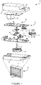
- FIG. 1 is an exploded view of an exemplary actuator 10, e.g., for use with a damper 12.
- the actuator 10 can include a lower housing 11 and a top housing 13 which are configured to receive a rotatable output coupler 14 through coupling holes 16 via a bearing rings 18.
- the coupler 14 is constructed to operatively couple to an external device such as the damper 12 or a valve, and is adapted to displace louvers 13 of the damper 12 between a default stasis position in the event of a power interruption and a desired operating position when power is being applied to the actuator 10.
- the actuator 10 can be reversible to accommodate a normally closed damper 12 or a normally open damper 12 depending on how the actuator 10 is installed.
- the normally closed damper 12 can be used as a smoke exhaust in an elevator shaft to keep foreign object out of the shaft until the damper 12 is opened to allow smoke to vent out.
- the normally open damper 12 can allow fresh air to enter building space until there is a fire when the damper 12 is closed to prevent smoke from travelling through the damper 12 to that part of the building.
- the actuator 10 can include two modes, energized and de-energized, two energized states, high voltage and low voltage, and two de-energized states, rest and returning to stasis. Other modes and states can be used. For example, when the actuator 10 is energized, the actuator 10 can be driving under power or holding an end position. When the actuator 10 is de-energized, the actuator 10 can at rest or returning to the stasis state using a retracting spring 37. The actuator 10 moves the louvers 13 between open and closed positions, or vice versa, depending on when the actuator 10 is operating in an energized or de-energized state.
- the output coupler 14 of the actuator 10 includes an integral output segment 20 which has a plurality of teeth for engaging a gear train indicated generally at 22.
- the gear train 22 can include gear sets (e.g., four gear sets 24, 26, 28, 30) which are operatively engaged with respect to each other.
- the gear train 22 is arranged with the axes of the gear sets 24, 26, 28, 30 generally forming a zig-zag line along the longitudinal direction of the actuator 10.
- the gear set 24 of the gear train 22 is engaged with the output segment 20 of the output coupler 14 and the gear set 30 is operatively engaged with a drive motor 34. In this manner, the torque produced by the motor 34 is transferred and amplified by the gear train 22 to the output coupler 14 when the drive motor 34 is energized.
- gear train 22 is arranged using the interconnection of four gear sets 24, 26, 28, 30 including their respective transfer pinions, gear train 22 may include more or less than four gear sets, and can be arranged in various other configurations which would allow torque to be transferred between the drive motor 34 and the output coupler 14.
- the actuator 10 further includes a switching circuit (e.g., any of the switching circuits described in Figure 2-7 below) for controlling power that is applied to the drive motor 34 and the solenoid 46.
- the switching circuit can be implemented on a printed circuit board 42 and can be protected by an insulation plate.
- FIG. 2 is a schematic of an exemplary switching circuit 200 for the actuator 10.
- the circuit 200 includes a transformer 202.
- Input terminals 204 on a primary side of the transformer 202 can include, for example, 24V, 115V and/or 230V at 50Hz or 60Hz inputs.
- the output terminals 206 on the secondary side of the transformer 202 can include a high voltage (HV) alternating current (AC) hot output 208, a high voltage (HV) alternating current (AC) return output 210, a low voltage (LV) alternating current (AC) hot output 212, and a low voltage (LV) alternating current (AC) return output 214.
- the high voltages at terminals 208 and 210 can provide the driving voltage for the actuator 10 and the low voltages at terminals 212 and 214 can provide the hold voltage for the actuator 10.
- the actuator 10 moves the damper 12 from zero to ninety degrees (e.g., from a normally closed to an open position, or a normally open to a closed position) the drive voltage moves the damper 12 to the end stop position and changes to the hold voltage to provide enough power to help maintain the damper 12 at the end stop position.
- the damper 12 can return to its starting, stasis state, e.g., open or closed.
- the output voltages from the outputs 208, 210, 212 and 214 can be applied to a rectifier bridge, e.g., low voltage rectifier bridge 220 and high voltage rectifier bridge 230.
- the rectifier bridges 220, 230 include diodes 222, 224, 226, 228, 232, 234, 236, 238, e.g., in one implementation 1N5408 type diodes.
- the rectifiers 220, 230 transform the AC voltage to DC voltage, e.g., about an 8V unregulated DC voltage 240 for the hold voltage and about a 24V unregulated high DC voltage 242.
- the unregulated high DC 24V can be used as the high drive voltage for driving the motor 34 to move the damper 12 from a closed to open state, or open to closed depending on the configuration. (See also Figure 4 ).
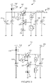
- FIG 3 is a schematic of exemplary regulator circuits 300 for the actuator 10.
- Regulator circuit 310 receives the 24V unregulated high DC voltage at input terminal 312 which is sent through a blocking diode 314 and outputs about a regulated 12V output at terminal 316 for powering the circuits (e.g., switching circuit 400 described in Figure 4 ).
- the regulator circuit 310 can include switches 318, 320, resistors 322, 324, 326, capacitors 328, 330 and diode 332 to regulate the unregulated 24V input voltage.
- exemplary values of elements 314, 318, 320, 322, 324, 326, 328, 330 and 332 are provided, but other values can be used.
- Regulator circuit 340 receives unregulated low DC voltage input 240 (e.g., about 8V) and sends the unregulated low DC voltage through a blocking diode 344.
- the regulator circuit uses switches 348, 350, resistors 352, 354, 356, capacitors 358, 360, 362, 364 and diode 366 to output a regulated low DC voltage 346, e.g., 5V.
- the 5V regulated low DC voltage can provide the actuator holding voltage in the energized low voltage state (see also Figure 4 ).
- exemplary values of elements 344, 348, 350, 352, 354, 356, 358, 360, 362, 364 and 366 are provided, but other values can be used.
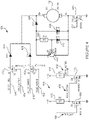
- FIG. 4 is a schematic of an exemplary switching circuit 400 for controlling switching from the high voltage state to low voltage state in the energized mode.
- the switching circuit 400 can advantageously replace a single throw, double pole switch.
- the switching circuit 400 switches from providing a drive active signal 402 to a hold active signal 404 based on a timer signal 406.
- the drive active signal 402 and the hold active signal 404 can control whether unregulated high DC driving voltage 242 or regulated low DC holding voltage 346 is sent to the drive motor 34.
- the timer signal 406 can be received from an embedded memory, discrete timer circuit component or microcontroller, e.g., MC14541B by MOTOROLA when cost is not a factor, or other time producing circuit.
- the timer signal 406 is sent for a determined amount of time, e.g., about 10 to 15 seconds, or other time after the actuator 10 is activated for the damper 12 to reach the end stop position or other determined position.
- the spring 37 can act as a variable clutch to absorb shock and remove torque when the damper 12 reaches the end stop position and the actuator is driving.
- the spring 37 can be located between the gear sets 24, 26, 28, 30 of the gear train.
- the switching circuit 400 can include first and second semiconductor switches 408, 410 and resistors 412, 414 with each of the resistors 412, 414 connected to an output terminal of respective semiconductor switches 408, 410 and reference voltage, e.g., 12V.
- first switch 408 When the timer signal 406 is received or present on the gate input (G) of first switch 408 the first switch 408 is activated (e.g., a voltage is applied at the gate (G) of semiconductor switch 408) the hold active signal 404 is pulled to ground.
- the second semiconductor switch 410 is off since the voltage at gate (G) of semiconductor switch 410 is pulled low. Since the semiconductor switch 410 is off, the drive active signal 402 is high as received by the third switch 426 of motor circuit 420.
- the hold active signal 404 is low as received by the fourth switch 422 of the motor circuit 420. Therefore, the third semiconductor switch 426 is on and the high voltage (HV) DC unregulated 24V high driving voltage is received by the motor 34 to drive the damper 12 out of the stasis position.
- the fourth semiconductor switch 422 is off.
- the first semiconductor switch 408 When the timer signal 406 reaches the determined time and the timer signal 406 goes low, the first semiconductor switch 408 is turned off which means the hold active signal 404 is high as received by the fourth switch 422 of the motor circuit 420.
- the second semiconductor switch 410 is on, and the drive active signal 402 is pulled to ground. Therefore, the third semiconductor switch 426 is off and the fourth semiconductor switch 422 is on, and low holding voltage, e.g., (LV) DC regulated 5V, is supplied to the motor 34 to hold the motor in the energized, non-stasis state.
- the motor circuit 420 includes diode 424 corresponding to fourth semiconductor switch 422, and diode 428 corresponding to semiconductor switch 426.
- the semiconductor switches 422, 426 are metal-oxide semiconductor field-effect transistor (MOSFET) switches.
- MOSFET metal-oxide semiconductor field-effect transistor
- the semiconductor switches 408, 410, 422 and 426 can replace a single throw, double pole switch.
- relays or other types of switches can be used in place of the semiconductor switches.
- a fifth semiconductor switch 440 ensures that in the de-energized mode when no power is applied to the motor 34 as identified by the voltage at the gate (G) of fifth semiconductor switch 440, the switch 440 is off and diodes 442, 444, 446, resistor 448 and switch 450 connected in parallel with the drive motor 34 to provide an electrical load against the drive motor 34 as the retracting spring 37 returns the damper 12 to a stasis state. Voltage generated by the drive motor 34 being driven by the spring 37 is also blocked from conducting though the switch 440 to connecting circuits.
- switch 440 When switch 440 is off, voltage generated by the drive motor 34 is forced to travel through diode 444 and diode 446 in the case of a low torque generator, and voltage travels through diode 442, diode 446, resistor 448 and switch 450 in the case of a high torque generator. Switch 450, diode 442 and resistor 448 are acting as a zener diode.
- the load applied to the drive motor 34 allows the damper 12 to return to a stasis position in a controlled manner and prevents voltage from the drive motor 34 from harming parts of the circuit.
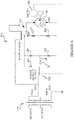
- FIG. 5 is a schematic of another exemplary switching circuit 500 for the actuator 10.
- the circuit 500 includes a relay 510 that switches the circuit between a driving mode 512 and a holding mode 514 for the motor 34.
- a transformer 516 can provide more power for the driving mode 512, e.g., 220V, 230V, or 240V and less power for the holding mode 514, e.g., 110V, 120V, 130V.
- the circuit 500 can include a MOSFET connected with the negative terminal of the drive motor 34 and a gate of the MOSFET connected to a resistor/capacitor (RC) bridge to provide load to the drive motor 34.
- the relay 510 can in some implementations make for more stable switching than the MOSFET.
- the relay 510 connects with a diode bridge of diodes 522, 524, 526, 528, via a drive/hold switch 530.
- the diode bridge of diodes 522, 524, 526, 528 rectifies the AC voltage from the transformer 516 to DC voltage for the drive motor 34.
- the drive/hold switch 530 selects between the driving mode 512 and holding mode 514 voltage of the transformer 516 to provide drive power to the drive motor 34 when the damper 12 moves from the stasis position and hold power to maintain the damper 12 at the end stop. For example, with the drive/hold switch 530 in the hold position the voltage is from a center tap of the transformer 516 to ground to provide half the drive voltage.
- the drive/hold switch 530 can be implemented, for example, with a single pole, double throw switch. Other switch types can be used.
- the relay 510 controls active/return selection of the circuit 500. In the active (e.g., energized) mode the relay 510 is switched to supply drive and then hold power to the drive motor 34. In the return (e.g., de-energized) mode, the relay 510 connects the drive motor 34 to diode 540 and zener diode 542 combination to provide a braking load for the drive motor 34, e.g., when no power is supplied to the drive motor 34 and the damper 12 is returning to the stasis state, e.g., under spring power.
- the drive motor 34 connects to the drive train 550 which connects with the damper 12 to provide opening or closing of the damper 12.
- the gear train 550 can connect to the drive/hold switch 530 to make the drive mode 512 and hold mode 514 selection, for example, based on the drive train 550 moving the damper 12 a determined distance, e.g., measured in degrees, from stasis.
- Advantages of the circuit 500 include a small number of parts compared to past damper actuators, no pulse width modulator or microcontroller is needed, heat loss can be minimized, the return zener is not taxed while on hold, and low hold power can be utilized.
- Figure 6 is a flowchart of an exemplary logic 600 collectively performed by the switching circuits in Figures 2-7 having different modes as described herein. If power is being applied by the actuator 10 (block 610), it is determined whether the end position of the louvers 13 has been reached (block 620). The end position can be determined to have been reached after a determined amount of time since the power was application, after the gear sets 24, 26, 28, 30 have moved a determined distance, a switch at the end point is activated, etc., depending on an implementation. If the end position has not yet been reached, the actuator continues to provide the higher driver voltage (block 630). If the end position has been determined to have been reached, the actuator supplies the lower hold voltage (block 640).
- the damper 12 and actuator 10 are in stasis. If the louvers 13 not located in a home position (block 650), the retracting spring moves the louvers 13 to the home position and turns the drive motor 34 into a generator (block 660).
- a zener e.g., described for the above circuitry, can load the drive motor 34 in that case.
- FIG. 7 is a schematic of another exemplary switching circuit 700 for the actuator 10.
- a MOSFET 710, or other semiconductor device, and resistors 712, 714 performs the switching for energized driving mode 512 voltage and holding mode 514 voltage, e.g., instead of the relay 510 of Figure 5 .
- the MOSFET turns off and the diode 540/zener diode 542 combination becomes active.
- the regulator circuits of Figure 3 can be used to regulate the voltage received by the MOSFET 710. No pulse width modulator, relay or microcontroller is needed to accommodate the damper drive power and hold power modes for this circuit.
Landscapes
- Engineering & Computer Science (AREA)
- Power Engineering (AREA)
- Physics & Mathematics (AREA)
- Thermal Sciences (AREA)
- Mechanical Engineering (AREA)
- Control Of Direct Current Motors (AREA)
- Control Of Stepping Motors (AREA)
- Control Of Electric Motors In General (AREA)
- Power-Operated Mechanisms For Wings (AREA)
Description
- The present embodiments relate generally to systems and methods for a damper actuator without a microcontroller.
- Dampers, e.g., in heating, ventilating and air conditioning (HVAC) installations, can include valves or plates that stop or regulate the flow of air inside a duct, chimney, variable air volume (VAV) box, air handler, or other air handling equipment. Fire dampers are fitted where ductwork passes through fire compartment walls/fire curtains as part of a fire control strategy. A damper actuator can control the opening and closing of the damper. The damper actuator allows a damper system to bring in outside air, smoke outside and/or moves the damping system in such a way that air cannot get in. Conventional actuators typically require microcontrollers which can lead to extra parts and costs of the actuators. Haines, R. W. describes electric and electronic control devices ("Control Systems for Heating, Ventilating and Air Controlling," van Nostrand, Reinhold, page 41-176, 1987).
US 2007/176758 A1 relates to a system for maintaining appropriate control of an actuator in the event of a power disruption without being adversely affected by the period of the power disruption. The actuator may close during the power disruption but will be fully opened upon the return of power to the system. After being opened, the actuator may be kept open with less power than needed for opening it.US 4 185 770 A provides an automatic flue damper assembly of the type in which the motor of a clockwork mechanism is energized to hold the damper closed and the mechanism is mechanically biased to move the damper to an open position in the absence of motor energization, a stopping or braking arrangement is provided which applies DC to the motor for dynamic braking as the damper closely approaches its open position - The present invention provides an actuator adapted to provide drive power and hold power to an external device, comprising: a motor provided for driving the external device to a determined position when the motor is energized; a switching circuit configured to energize the motor with a high voltage to drive the external device to the determined position and energize the motor with a low voltage to hold the external device in the determined position; wherein the switching circuit comprises a drive/hold switch connected with the motor, the drive/hold switch configured to select a high voltage or a low voltage, the high voltage for energizing the motor to drive the external device to the determined position, and the low voltage for energizing the motor to hold the external device when a determined time has passed from a moment the motor is energized, where the low voltage is lower than the high voltage; and an active/return switch connected with the motor, the active/return switch is a relay configured to: in a de-energized mode, connect the motor with a combination of a diode and a zener diode and disconnect the motor from the high voltage or low voltage selected by the drive/hold switch to provide a braking load for the motor when no power is supplied to the motor and the external device is returning a stasis state under spring power; and in an energized mode, supply the high voltage or the low voltage selected by the drive/hold switch to the motor and disconnect the motor from the combination of the diode and the zener diode, as defined by
claim 1. - The present invention provides a method for providing drive power and hold power to an external device, characterized by: selecting, with a switching circuit, a high voltage or a low voltage, the high voltage for energizing a motor to drive the external device to a determined position, and the low voltage to hold the external device when a determined time has passed from a moment the motor is energized, where the low voltage is lower than the high voltage; and in a de-energized mode, connecting, with an active/return switch which is a relay, the motor with a combination of a diode and a zener diode and disconnect the motor from the high voltage or low voltage selected by a drive/hold switch of the switching circuit thereby providing a braking load to the motor when no power is supplied to the motor and the external device is returning a stasis state under spring power; and in an energized mode, supplying, with the active/return switch, the high voltage or the low voltage selected by the drive/hold switch to the motor and disconnect the motor from the combination of the diode and the zener diode, as defined by
claim 4. - Other systems, methods, features, and advantages will be or will become apparent upon examination of the following figures and detailed description. It is intended that all such additional systems, methods, features, and advantages be included within this description and be protected by the accompanying claims.
- The accompanying drawings, which are incorporated in and constitute a part of this specification, illustrate an implementation of the present embodiments and, together with the description, serve to explain the advantages and principles of the embodiments. In the drawings:
-
Figure 1 is an exploded view of an exemplary actuator, e.g., for use with a damper. -
Figure 2 is a schematic of an exemplary switching circuit for the actuator. -
Figure 3 is a schematic of exemplary regulator circuits for the actuator. -
Figure 4 is a schematic of an exemplary switching circuit for controlling switching from the high voltage state to low voltage state in the energized mode. -
Figure 5 is a schematic of another exemplary switching circuit for the actuator. -
Figure 6 is a flowchart of an exemplary logic for the different modes of the circuits described herein. -
Figure 7 is a schematic of another exemplary switching circuit for the actuator. - Reference will now be made in detail to the description of the embodiments as illustrated in the drawings. While the embodiments will be described in connection with these drawings, there is no intent to limit it to the embodiment(s) disclosed. The invention is defined by the device of
claim 1 and the method ofclaim 4. Preferred embodiments of invention are disclosed independent claims - System and methods for a damper actuator without a microcontroller can be used with direct current (DC) motors and line voltage motors, etc., e.g., GND and GGD type of fire and smoke damper actuators by SIEMENS INDUSTRY INC. BUILDING TECHNOLOGIES DIVISION.
-
Figure 1 is an exploded view of anexemplary actuator 10, e.g., for use with adamper 12. Theactuator 10 can include alower housing 11 and atop housing 13 which are configured to receive arotatable output coupler 14 throughcoupling holes 16 via abearing rings 18. Thecoupler 14 is constructed to operatively couple to an external device such as thedamper 12 or a valve, and is adapted to displacelouvers 13 of thedamper 12 between a default stasis position in the event of a power interruption and a desired operating position when power is being applied to theactuator 10. Theactuator 10 can be reversible to accommodate a normally closeddamper 12 or a normallyopen damper 12 depending on how theactuator 10 is installed. For example, the normally closeddamper 12 can be used as a smoke exhaust in an elevator shaft to keep foreign object out of the shaft until thedamper 12 is opened to allow smoke to vent out. The normallyopen damper 12 can allow fresh air to enter building space until there is a fire when thedamper 12 is closed to prevent smoke from travelling through thedamper 12 to that part of the building. - The
actuator 10 can include two modes, energized and de-energized, two energized states, high voltage and low voltage, and two de-energized states, rest and returning to stasis. Other modes and states can be used. For example, when theactuator 10 is energized, theactuator 10 can be driving under power or holding an end position. When theactuator 10 is de-energized, theactuator 10 can at rest or returning to the stasis state using a retractingspring 37. Theactuator 10 moves thelouvers 13 between open and closed positions, or vice versa, depending on when theactuator 10 is operating in an energized or de-energized state. - The
output coupler 14 of theactuator 10 includes anintegral output segment 20 which has a plurality of teeth for engaging a gear train indicated generally at 22. Thegear train 22 can include gear sets (e.g., fourgear sets gear train 22 is arranged with the axes of thegear sets actuator 10. The gear set 24 of thegear train 22 is engaged with theoutput segment 20 of theoutput coupler 14 and thegear set 30 is operatively engaged with adrive motor 34. In this manner, the torque produced by themotor 34 is transferred and amplified by thegear train 22 to theoutput coupler 14 when thedrive motor 34 is energized. While thegear train 22 is arranged using the interconnection of fourgear sets gear train 22 may include more or less than four gear sets, and can be arranged in various other configurations which would allow torque to be transferred between thedrive motor 34 and theoutput coupler 14. - An
elongated shaft 36 which is concentric with the axis of thegear 28 depends from this gear. A slotted sleeve is attached to the end of theshaft 36 and is adapted to be connected to an end of the retractingspring 37, for example, a clock or torsion spring, e.g., double wrap spring clutch. When thedamper 12 is displaced away from the default position by theoutput coupler 14, the retractingspring 37 is placed under a state of torsion, and applies a force on theoutput coupler 14 via thegear train 22 to return thedamper 12 to its default position. Theactuator 10 further includes a switching circuit (e.g., any of the switching circuits described inFigure 2-7 below) for controlling power that is applied to thedrive motor 34 and the solenoid 46. The switching circuit can be implemented on a printedcircuit board 42 and can be protected by an insulation plate. -
Figure 2 is a schematic of anexemplary switching circuit 200 for theactuator 10. Thecircuit 200 includes atransformer 202.Input terminals 204 on a primary side of thetransformer 202 can include, for example, 24V, 115V and/or 230V at 50Hz or 60Hz inputs. Theoutput terminals 206 on the secondary side of thetransformer 202 can include a high voltage (HV) alternating current (AC)hot output 208, a high voltage (HV) alternating current (AC)return output 210, a low voltage (LV) alternating current (AC)hot output 212, and a low voltage (LV) alternating current (AC)return output 214. The high voltages atterminals actuator 10 and the low voltages atterminals actuator 10. For example, when theactuator 10 moves thedamper 12 from zero to ninety degrees (e.g., from a normally closed to an open position, or a normally open to a closed position) the drive voltage moves thedamper 12 to the end stop position and changes to the hold voltage to provide enough power to help maintain thedamper 12 at the end stop position. When power is removed from theoutputs damper 12 can return to its starting, stasis state, e.g., open or closed. - The output voltages from the
outputs voltage rectifier bridge 220 and highvoltage rectifier bridge 230. The rectifier bridges 220, 230 includediodes rectifiers unregulated DC voltage 240 for the hold voltage and about a 24V unregulatedhigh DC voltage 242. The unregulatedhigh DC 24V can be used as the high drive voltage for driving themotor 34 to move thedamper 12 from a closed to open state, or open to closed depending on the configuration. (See alsoFigure 4 ). -
Figure 3 is a schematic ofexemplary regulator circuits 300 for theactuator 10.Regulator circuit 310 receives the 24V unregulated high DC voltage atinput terminal 312 which is sent through a blocking diode 314 and outputs about a regulated 12V output atterminal 316 for powering the circuits (e.g., switchingcircuit 400 described inFigure 4 ). Theregulator circuit 310 can includeswitches resistors capacitors diode 332 to regulate the unregulated 24V input voltage. For purposes of explanation exemplary values ofelements -
Regulator circuit 340 receives unregulated low DC voltage input 240 (e.g., about 8V) and sends the unregulated low DC voltage through a blockingdiode 344. The regulator circuit usesswitches resistors capacitors diode 366 to output a regulatedlow DC voltage 346, e.g., 5V. The 5V regulated low DC voltage can provide the actuator holding voltage in the energized low voltage state (see alsoFigure 4 ). For purposes of explanation exemplary values ofelements -
Figure 4 is a schematic of anexemplary switching circuit 400 for controlling switching from the high voltage state to low voltage state in the energized mode. Theswitching circuit 400 can advantageously replace a single throw, double pole switch. Theswitching circuit 400 switches from providing a driveactive signal 402 to a holdactive signal 404 based on atimer signal 406. The driveactive signal 402 and the holdactive signal 404 can control whether unregulated highDC driving voltage 242 or regulated lowDC holding voltage 346 is sent to thedrive motor 34. Referring to theswitching circuit 400, thetimer signal 406 can be received from an embedded memory, discrete timer circuit component or microcontroller, e.g., MC14541B by MOTOROLA when cost is not a factor, or other time producing circuit. Thetimer signal 406 is sent for a determined amount of time, e.g., about 10 to 15 seconds, or other time after theactuator 10 is activated for thedamper 12 to reach the end stop position or other determined position. Thespring 37 can act as a variable clutch to absorb shock and remove torque when thedamper 12 reaches the end stop position and the actuator is driving. Thespring 37 can be located between the gear sets 24, 26, 28, 30 of the gear train. - The
switching circuit 400 can include first and second semiconductor switches 408, 410 andresistors resistors timer signal 406 is received or present on the gate input (G) offirst switch 408 thefirst switch 408 is activated (e.g., a voltage is applied at the gate (G) of semiconductor switch 408) the holdactive signal 404 is pulled to ground. Thesecond semiconductor switch 410 is off since the voltage at gate (G) ofsemiconductor switch 410 is pulled low. Since thesemiconductor switch 410 is off, the driveactive signal 402 is high as received by thethird switch 426 ofmotor circuit 420. The holdactive signal 404 is low as received by thefourth switch 422 of themotor circuit 420. Therefore, thethird semiconductor switch 426 is on and the high voltage (HV) DC unregulated 24V high driving voltage is received by themotor 34 to drive thedamper 12 out of the stasis position. Thefourth semiconductor switch 422 is off. - When the
timer signal 406 reaches the determined time and thetimer signal 406 goes low, thefirst semiconductor switch 408 is turned off which means the holdactive signal 404 is high as received by thefourth switch 422 of themotor circuit 420. Thesecond semiconductor switch 410 is on, and the driveactive signal 402 is pulled to ground. Therefore, thethird semiconductor switch 426 is off and thefourth semiconductor switch 422 is on, and low holding voltage, e.g., (LV) DC regulated 5V, is supplied to themotor 34 to hold the motor in the energized, non-stasis state. Themotor circuit 420 includesdiode 424 corresponding tofourth semiconductor switch 422, anddiode 428 corresponding tosemiconductor switch 426. In one implementation the semiconductor switches 422, 426 are metal-oxide semiconductor field-effect transistor (MOSFET) switches. The semiconductor switches 408, 410, 422 and 426 can replace a single throw, double pole switch. In other implementations relays or other types of switches can be used in place of the semiconductor switches. - A
fifth semiconductor switch 440 ensures that in the de-energized mode when no power is applied to themotor 34 as identified by the voltage at the gate (G) offifth semiconductor switch 440, theswitch 440 is off anddiodes resistor 448 and switch 450 connected in parallel with thedrive motor 34 to provide an electrical load against thedrive motor 34 as the retractingspring 37 returns thedamper 12 to a stasis state. Voltage generated by thedrive motor 34 being driven by thespring 37 is also blocked from conducting though theswitch 440 to connecting circuits. Whenswitch 440 is off, voltage generated by thedrive motor 34 is forced to travel throughdiode 444 anddiode 446 in the case of a low torque generator, and voltage travels throughdiode 442,diode 446,resistor 448 and switch 450 in the case of a high torque generator.Switch 450,diode 442 andresistor 448 are acting as a zener diode. The load applied to thedrive motor 34 allows thedamper 12 to return to a stasis position in a controlled manner and prevents voltage from thedrive motor 34 from harming parts of the circuit. -
Figure 5 is a schematic of anotherexemplary switching circuit 500 for theactuator 10. Thecircuit 500 includes arelay 510 that switches the circuit between a drivingmode 512 and a holdingmode 514 for themotor 34. Atransformer 516 can provide more power for the drivingmode 512, e.g., 220V, 230V, or 240V and less power for the holdingmode 514, e.g., 110V, 120V, 130V. Instead of arelay 510, in some implementations thecircuit 500 can include a MOSFET connected with the negative terminal of thedrive motor 34 and a gate of the MOSFET connected to a resistor/capacitor (RC) bridge to provide load to thedrive motor 34. Therelay 510, however, can in some implementations make for more stable switching than the MOSFET. - The
relay 510 connects with a diode bridge ofdiodes hold switch 530. The diode bridge ofdiodes transformer 516 to DC voltage for thedrive motor 34. The drive/hold switch 530 selects between the drivingmode 512 and holdingmode 514 voltage of thetransformer 516 to provide drive power to thedrive motor 34 when thedamper 12 moves from the stasis position and hold power to maintain thedamper 12 at the end stop. For example, with the drive/hold switch 530 in the hold position the voltage is from a center tap of thetransformer 516 to ground to provide half the drive voltage. The drive/hold switch 530 can be implemented, for example, with a single pole, double throw switch. Other switch types can be used. Therelay 510 controls active/return selection of thecircuit 500. In the active (e.g., energized) mode therelay 510 is switched to supply drive and then hold power to thedrive motor 34. In the return (e.g., de-energized) mode, therelay 510 connects thedrive motor 34 todiode 540 andzener diode 542 combination to provide a braking load for thedrive motor 34, e.g., when no power is supplied to thedrive motor 34 and thedamper 12 is returning to the stasis state, e.g., under spring power. - The
drive motor 34 connects to thedrive train 550 which connects with thedamper 12 to provide opening or closing of thedamper 12. Thegear train 550 can connect to the drive/hold switch 530 to make thedrive mode 512 and holdmode 514 selection, for example, based on thedrive train 550 moving the damper 12 a determined distance, e.g., measured in degrees, from stasis. Advantages of thecircuit 500 include a small number of parts compared to past damper actuators, no pulse width modulator or microcontroller is needed, heat loss can be minimized, the return zener is not taxed while on hold, and low hold power can be utilized. -
Figure 6 is a flowchart of anexemplary logic 600 collectively performed by the switching circuits inFigures 2-7 having different modes as described herein. If power is being applied by the actuator 10 (block 610), it is determined whether the end position of thelouvers 13 has been reached (block 620). The end position can be determined to have been reached after a determined amount of time since the power was application, after the gear sets 24, 26, 28, 30 have moved a determined distance, a switch at the end point is activated, etc., depending on an implementation. If the end position has not yet been reached, the actuator continues to provide the higher driver voltage (block 630). If the end position has been determined to have been reached, the actuator supplies the lower hold voltage (block 640). If the actuator is not applying power (block 610), and thelouvers 13 are located in a home position (block 650), thedamper 12 andactuator 10 are in stasis. If thelouvers 13 not located in a home position (block 650), the retracting spring moves thelouvers 13 to the home position and turns thedrive motor 34 into a generator (block 660). A zener, e.g., described for the above circuitry, can load thedrive motor 34 in that case. -
Figure 7 is a schematic of anotherexemplary switching circuit 700 for theactuator 10. AMOSFET 710, or other semiconductor device, andresistors mode 512 voltage and holdingmode 514 voltage, e.g., instead of therelay 510 ofFigure 5 . When the DC rectified gate voltage of the MOSFET drops below the threshold voltage, the MOSFET turns off and thediode 540/zener diode 542 combination becomes active. The regulator circuits ofFigure 3 can be used to regulate the voltage received by theMOSFET 710. No pulse width modulator, relay or microcontroller is needed to accommodate the damper drive power and hold power modes for this circuit. - While various embodiments of the present embodiments have been described, it will be apparent to those of skill in the art that many more embodiments and implementations are possible that are within the scope of these embodiments. Accordingly, the present embodiments are not to be restricted except in light of the attached claims.
Claims (5)
- An actuator (10) adapted to provide drive power and hold power to an external device, comprising:a motor (34) provided for driving the external device to a determined position when the motor (34) is energized;a switching circuit (500) configured to energize the motor (34) with a high voltage to drive the external device to the determined position and energize the motor (34) with a low voltage to hold the external device in the determined position;wherein the switching circuit (500) comprises a drive/hold switch (530) connected with the motor (34), the drive/hold switch (530) configured to select a high voltage or a low voltage, the high voltage for energizing the motor (34) to drive the external device to the determined position, and the low voltage to hold the external device when a determined time has passed from a moment the motor (34) is energized, where the low voltage is lower than the high voltage; andan active/return switch connected with the motor (34), the active/return switch is a relay (510) configured to: in a de-energized mode, connect the motor (34) with a combination of a diode (540) and a zener diode (542) and disconnect the motor (34) from the high voltage or low voltage selected by the drive/hold switch (530) to provide a braking load for the motor (34) when no power is supplied to the motor (34) and the external device is returning a stasis state under spring power; and in an energized mode, supply the high voltage or the low voltage selected by the drive/hold switch (530) to the motor (34) and disconnect the motor (34) from the combination of the diode (540) and the zener diode (542).
- The actuator (10) of claim 1, where the determined time is determined by a distance travelled by a gear train (22, 550).
- The actuator (10) of claim 1, where the relay (510) connects the motor (34) to a transformer (202, 516) when power is applied to the motor (34).
- A method for providing drive power and hold power to an external device, comprising steps of:selecting, with a switching circuit (500), a high voltage or a low voltage, the high voltage for energizing a motor (34) to drive the external device to a determined position, and the low voltage to hold the external device when a determined time has passed from a moment the motor (34) is energized, where the low voltage is lower than the high voltage; andin a de-energized mode, connecting, with an active/return switch which is a relay (510), the motor (34) with a combination of a diode (540) and a zener diode (542) and disconnect the motor (34) from the high voltage or low voltage selected by a drive/hold switch (530) of the switching circuit (500) thereby providing a braking load to the motor (34) when no power is supplied to the motor (34) and the external device is returning a stasis state under spring power; and in an energized mode, supplying, with the active/return switch, the high voltage or the low voltage selected by the drive/hold switch (530) to the motor (34) and disconnect the motor (34) from the combination of the diode (540) and the zener diode (542).
- The method of claim 4, where the time is determined by a distance a gear train (22, 550) travels after the motor (34) is energized.
Applications Claiming Priority (1)
| Application Number | Priority Date | Filing Date | Title |
|---|---|---|---|
| PCT/US2014/057328 WO2016048315A1 (en) | 2014-09-25 | 2014-09-25 | Systems and methods for damper actuator without microcontroller |
Publications (3)
| Publication Number | Publication Date |
|---|---|
| EP3197694A1 EP3197694A1 (en) | 2017-08-02 |
| EP3197694A4 EP3197694A4 (en) | 2018-06-27 |
| EP3197694B1 true EP3197694B1 (en) | 2022-05-04 |
Family
ID=55581637
Family Applications (1)
| Application Number | Title | Priority Date | Filing Date |
|---|---|---|---|
| EP14902634.6A Active EP3197694B1 (en) | 2014-09-25 | 2014-09-25 | Systems and methods for damper actuator without microcontroller |
Country Status (6)
| Country | Link |
|---|---|
| US (1) | US10112456B2 (en) |
| EP (1) | EP3197694B1 (en) |
| CN (1) | CN106715169B (en) |
| CA (1) | CA2962423C (en) |
| MX (1) | MX2017003700A (en) |
| WO (1) | WO2016048315A1 (en) |
Families Citing this family (8)
| Publication number | Priority date | Publication date | Assignee | Title |
|---|---|---|---|---|
| GB201603283D0 (en) * | 2016-02-25 | 2016-04-13 | Johnson Electric Sa | Method of reducing noise from a HVAC system |
| JP7060983B2 (en) * | 2018-02-26 | 2022-04-27 | Joyson Safety Systems Japan株式会社 | Seatbelt retractor and seatbelt take-up mechanism |
| FR3080234B1 (en) * | 2018-04-13 | 2021-09-24 | Mmt ag | COMPACT LINEAR ELECTRIC ACTUATOR WITH ELASTIC DRIVE CHAIN |
| US12003146B2 (en) | 2020-03-02 | 2024-06-04 | Falcon Power, LLC | Cascade MosFet design for variable torque generator/motor gear switching |
| BR112022016869A2 (en) * | 2020-03-02 | 2022-10-18 | Falcon Power Llc | COOLING SYSTEM FOR VARIABLE TORQUE GENERATION ELECTRICAL MACHINE |
| WO2021228780A1 (en) * | 2020-05-11 | 2021-11-18 | Rotiny Aps | Actuator for fluid flow controllers |
| NL2028970B1 (en) * | 2021-08-13 | 2023-02-23 | Mci Mirror Controls Int Netherlands B V | Method for controlling a position of an actuable objection of a vehicle |
| CN114301366B (en) * | 2021-12-24 | 2024-05-31 | 兰州飞行控制有限责任公司 | Damper switching circuit controlled by electromagnetic relay |
Citations (4)
| Publication number | Priority date | Publication date | Assignee | Title |
|---|---|---|---|---|
| US5712548A (en) * | 1997-01-16 | 1998-01-27 | Eti Systems, Inc. | Bi-directional motor actuator |
| US6249100B1 (en) * | 1997-07-31 | 2001-06-19 | Honeywell International Inc. | Drive circuit and method for an electric actuator with spring return |
| US20070176570A1 (en) * | 2006-01-30 | 2007-08-02 | Honeywell International Inc. | Inverter loop latch with integrated ac detection reset |
| US7477028B2 (en) * | 2006-01-30 | 2009-01-13 | Honeywell International Inc. | Actuator control system |
Family Cites Families (8)
| Publication number | Priority date | Publication date | Assignee | Title |
|---|---|---|---|---|
| US4185770A (en) * | 1978-04-27 | 1980-01-29 | Westinghouse Electric Corp. | Automatic flue damper control system |
| US4911065A (en) | 1989-04-11 | 1990-03-27 | Philips Industrial Components Inc. | Damper with override control |
| US5278454B1 (en) | 1992-06-22 | 1995-05-23 | Nat Environment Products Ltd | Emergency capacitive energy source and circuit for damper motors and actuator motors |
| US6369540B1 (en) | 2000-11-21 | 2002-04-09 | Honeywell International Inc. | Bypass circuit for use in DC brush motor control |
| US20020175305A1 (en) | 2001-05-25 | 2002-11-28 | Mccabe Francis J. | Multiblade damper with DC actuator and double knee lock blade operator |
| US7033268B2 (en) | 2003-04-17 | 2006-04-25 | Siemens Building Technologies, Inc. | Multi-mode damper actuator |
| WO2005021914A1 (en) * | 2003-09-03 | 2005-03-10 | Dpnkd Holdings Inc. | Automatic portable door operating system |
| CH700541A1 (en) | 2009-03-02 | 2010-09-15 | Belimo Holding Ag | Driving device for a fire damper. |
-
2014
- 2014-09-25 MX MX2017003700A patent/MX2017003700A/en unknown
- 2014-09-25 CA CA2962423A patent/CA2962423C/en active Active
- 2014-09-25 CN CN201480082206.1A patent/CN106715169B/en active Active
- 2014-09-25 EP EP14902634.6A patent/EP3197694B1/en active Active
- 2014-09-25 WO PCT/US2014/057328 patent/WO2016048315A1/en not_active Ceased
- 2014-09-25 US US15/512,809 patent/US10112456B2/en active Active
Patent Citations (4)
| Publication number | Priority date | Publication date | Assignee | Title |
|---|---|---|---|---|
| US5712548A (en) * | 1997-01-16 | 1998-01-27 | Eti Systems, Inc. | Bi-directional motor actuator |
| US6249100B1 (en) * | 1997-07-31 | 2001-06-19 | Honeywell International Inc. | Drive circuit and method for an electric actuator with spring return |
| US20070176570A1 (en) * | 2006-01-30 | 2007-08-02 | Honeywell International Inc. | Inverter loop latch with integrated ac detection reset |
| US7477028B2 (en) * | 2006-01-30 | 2009-01-13 | Honeywell International Inc. | Actuator control system |
Also Published As
| Publication number | Publication date |
|---|---|
| CN106715169A (en) | 2017-05-24 |
| EP3197694A1 (en) | 2017-08-02 |
| CA2962423A1 (en) | 2016-03-31 |
| CA2962423C (en) | 2019-08-27 |
| WO2016048315A1 (en) | 2016-03-31 |
| EP3197694A4 (en) | 2018-06-27 |
| US20170282687A1 (en) | 2017-10-05 |
| CN106715169B (en) | 2020-04-14 |
| US10112456B2 (en) | 2018-10-30 |
| MX2017003700A (en) | 2017-06-30 |
Similar Documents
| Publication | Publication Date | Title |
|---|---|---|
| CA2962423C (en) | Systems and methods for damper actuator without microcontroller | |
| McDowall | Fundamentals of HVAC Control Systems: SI Edition Hardbound Book | |
| US7021072B2 (en) | Current control loop for actuator and method | |
| US4423364A (en) | Electric motor damper drive with backup power pack | |
| CN112105857B (en) | Electromagnetic switching valve position detection system | |
| US7023163B2 (en) | Fail-safe electric actuator using high voltage capacitors | |
| KR101502217B1 (en) | Electric actuator | |
| JP2011113781A (en) | Electronic control device | |
| US10859284B2 (en) | Solid-state common-wire adapter for smart communicating thermostats | |
| JP5993609B2 (en) | Electric actuator | |
| US4196848A (en) | Automatic thermostat set-back control system | |
| JP5315972B2 (en) | Shut-off valve | |
| US20150270794A1 (en) | Soft-start control for electromechanical devices using a resistor-capacitor circuit | |
| JP2006034000A (en) | Inrush current prevention circuit for air conditioner | |
| JP6751169B2 (en) | Valve actuator | |
| CA2980547C (en) | Stored energy for failsafe valve | |
| JP3914184B2 (en) | Burning appliance | |
| CN112969892B (en) | Self-adjusting setting device for flow regulating valve and method for self-adjusting setting | |
| US1518619A (en) | System of motor control | |
| JP5997497B2 (en) | Electric actuator | |
| US20120139457A1 (en) | Electronic drive having an electro-mechanical break | |
| JP2017158291A (en) | Power supply device and lighting device | |
| HK1260865B (en) | Valve train | |
| JPS6364864B2 (en) |
Legal Events
| Date | Code | Title | Description |
|---|---|---|---|
| STAA | Information on the status of an ep patent application or granted ep patent |
Free format text: STATUS: THE INTERNATIONAL PUBLICATION HAS BEEN MADE |
|
| PUAI | Public reference made under article 153(3) epc to a published international application that has entered the european phase |
Free format text: ORIGINAL CODE: 0009012 |
|
| STAA | Information on the status of an ep patent application or granted ep patent |
Free format text: STATUS: REQUEST FOR EXAMINATION WAS MADE |
|
| 17P | Request for examination filed |
Effective date: 20170302 |
|
| AK | Designated contracting states |
Kind code of ref document: A1 Designated state(s): AL AT BE BG CH CY CZ DE DK EE ES FI FR GB GR HR HU IE IS IT LI LT LU LV MC MK MT NL NO PL PT RO RS SE SI SK SM TR |
|
| AX | Request for extension of the european patent |
Extension state: BA ME |
|
| DAX | Request for extension of the european patent (deleted) | ||
| A4 | Supplementary search report drawn up and despatched |
Effective date: 20180525 |
|
| RIC1 | Information provided on ipc code assigned before grant |
Ipc: A62C 2/24 20060101ALI20180518BHEP Ipc: H02P 7/06 20060101ALI20180518BHEP Ipc: H02P 3/02 20060101ALI20180518BHEP Ipc: B60H 1/00 20060101AFI20180518BHEP Ipc: H02P 1/18 20060101ALI20180518BHEP Ipc: E05F 3/22 20060101ALI20180518BHEP Ipc: E05F 15/41 20150101ALI20180518BHEP Ipc: H02P 7/03 20160101ALI20180518BHEP Ipc: F16H 19/00 20060101ALI20180518BHEP |
|
| STAA | Information on the status of an ep patent application or granted ep patent |
Free format text: STATUS: EXAMINATION IS IN PROGRESS |
|
| 17Q | First examination report despatched |
Effective date: 20201006 |
|
| REG | Reference to a national code |
Ref country code: DE Ref legal event code: R079 Ref document number: 602014083623 Country of ref document: DE Free format text: PREVIOUS MAIN CLASS: B60H0001000000 Ipc: E05F0015600000 |
|
| GRAP | Despatch of communication of intention to grant a patent |
Free format text: ORIGINAL CODE: EPIDOSNIGR1 |
|
| STAA | Information on the status of an ep patent application or granted ep patent |
Free format text: STATUS: GRANT OF PATENT IS INTENDED |
|
| RIC1 | Information provided on ipc code assigned before grant |
Ipc: H02P 1/18 20060101ALI20220121BHEP Ipc: H02P 3/02 20060101ALI20220121BHEP Ipc: H02P 7/06 20060101ALI20220121BHEP Ipc: B60H 1/00 20060101ALI20220121BHEP Ipc: E05F 15/60 20150101AFI20220121BHEP |
|
| INTG | Intention to grant announced |
Effective date: 20220210 |
|
| GRAS | Grant fee paid |
Free format text: ORIGINAL CODE: EPIDOSNIGR3 |
|
| GRAA | (expected) grant |
Free format text: ORIGINAL CODE: 0009210 |
|
| STAA | Information on the status of an ep patent application or granted ep patent |
Free format text: STATUS: THE PATENT HAS BEEN GRANTED |
|
| AK | Designated contracting states |
Kind code of ref document: B1 Designated state(s): AL AT BE BG CH CY CZ DE DK EE ES FI FR GB GR HR HU IE IS IT LI LT LU LV MC MK MT NL NO PL PT RO RS SE SI SK SM TR |
|
| REG | Reference to a national code |
Ref country code: GB Ref legal event code: FG4D |
|
| REG | Reference to a national code |
Ref country code: CH Ref legal event code: EP |
|
| REG | Reference to a national code |
Ref country code: AT Ref legal event code: REF Ref document number: 1489212 Country of ref document: AT Kind code of ref document: T Effective date: 20220515 |
|
| REG | Reference to a national code |
Ref country code: IE Ref legal event code: FG4D Ref country code: DE Ref legal event code: R096 Ref document number: 602014083623 Country of ref document: DE |
|
| REG | Reference to a national code |
Ref country code: LT Ref legal event code: MG9D |
|
| REG | Reference to a national code |
Ref country code: NL Ref legal event code: MP Effective date: 20220504 |
|
| REG | Reference to a national code |
Ref country code: AT Ref legal event code: MK05 Ref document number: 1489212 Country of ref document: AT Kind code of ref document: T Effective date: 20220504 |
|
| PG25 | Lapsed in a contracting state [announced via postgrant information from national office to epo] |
Ref country code: SE Free format text: LAPSE BECAUSE OF FAILURE TO SUBMIT A TRANSLATION OF THE DESCRIPTION OR TO PAY THE FEE WITHIN THE PRESCRIBED TIME-LIMIT Effective date: 20220504 Ref country code: PT Free format text: LAPSE BECAUSE OF FAILURE TO SUBMIT A TRANSLATION OF THE DESCRIPTION OR TO PAY THE FEE WITHIN THE PRESCRIBED TIME-LIMIT Effective date: 20220905 Ref country code: NO Free format text: LAPSE BECAUSE OF FAILURE TO SUBMIT A TRANSLATION OF THE DESCRIPTION OR TO PAY THE FEE WITHIN THE PRESCRIBED TIME-LIMIT Effective date: 20220804 Ref country code: NL Free format text: LAPSE BECAUSE OF FAILURE TO SUBMIT A TRANSLATION OF THE DESCRIPTION OR TO PAY THE FEE WITHIN THE PRESCRIBED TIME-LIMIT Effective date: 20220504 Ref country code: LT Free format text: LAPSE BECAUSE OF FAILURE TO SUBMIT A TRANSLATION OF THE DESCRIPTION OR TO PAY THE FEE WITHIN THE PRESCRIBED TIME-LIMIT Effective date: 20220504 Ref country code: HR Free format text: LAPSE BECAUSE OF FAILURE TO SUBMIT A TRANSLATION OF THE DESCRIPTION OR TO PAY THE FEE WITHIN THE PRESCRIBED TIME-LIMIT Effective date: 20220504 Ref country code: GR Free format text: LAPSE BECAUSE OF FAILURE TO SUBMIT A TRANSLATION OF THE DESCRIPTION OR TO PAY THE FEE WITHIN THE PRESCRIBED TIME-LIMIT Effective date: 20220805 Ref country code: FI Free format text: LAPSE BECAUSE OF FAILURE TO SUBMIT A TRANSLATION OF THE DESCRIPTION OR TO PAY THE FEE WITHIN THE PRESCRIBED TIME-LIMIT Effective date: 20220504 Ref country code: ES Free format text: LAPSE BECAUSE OF FAILURE TO SUBMIT A TRANSLATION OF THE DESCRIPTION OR TO PAY THE FEE WITHIN THE PRESCRIBED TIME-LIMIT Effective date: 20220504 Ref country code: BG Free format text: LAPSE BECAUSE OF FAILURE TO SUBMIT A TRANSLATION OF THE DESCRIPTION OR TO PAY THE FEE WITHIN THE PRESCRIBED TIME-LIMIT Effective date: 20220804 Ref country code: AT Free format text: LAPSE BECAUSE OF FAILURE TO SUBMIT A TRANSLATION OF THE DESCRIPTION OR TO PAY THE FEE WITHIN THE PRESCRIBED TIME-LIMIT Effective date: 20220504 |
|
| PG25 | Lapsed in a contracting state [announced via postgrant information from national office to epo] |
Ref country code: RS Free format text: LAPSE BECAUSE OF FAILURE TO SUBMIT A TRANSLATION OF THE DESCRIPTION OR TO PAY THE FEE WITHIN THE PRESCRIBED TIME-LIMIT Effective date: 20220504 Ref country code: PL Free format text: LAPSE BECAUSE OF FAILURE TO SUBMIT A TRANSLATION OF THE DESCRIPTION OR TO PAY THE FEE WITHIN THE PRESCRIBED TIME-LIMIT Effective date: 20220504 Ref country code: LV Free format text: LAPSE BECAUSE OF FAILURE TO SUBMIT A TRANSLATION OF THE DESCRIPTION OR TO PAY THE FEE WITHIN THE PRESCRIBED TIME-LIMIT Effective date: 20220504 Ref country code: IS Free format text: LAPSE BECAUSE OF FAILURE TO SUBMIT A TRANSLATION OF THE DESCRIPTION OR TO PAY THE FEE WITHIN THE PRESCRIBED TIME-LIMIT Effective date: 20220904 |
|
| PG25 | Lapsed in a contracting state [announced via postgrant information from national office to epo] |
Ref country code: SM Free format text: LAPSE BECAUSE OF FAILURE TO SUBMIT A TRANSLATION OF THE DESCRIPTION OR TO PAY THE FEE WITHIN THE PRESCRIBED TIME-LIMIT Effective date: 20220504 Ref country code: SK Free format text: LAPSE BECAUSE OF FAILURE TO SUBMIT A TRANSLATION OF THE DESCRIPTION OR TO PAY THE FEE WITHIN THE PRESCRIBED TIME-LIMIT Effective date: 20220504 Ref country code: RO Free format text: LAPSE BECAUSE OF FAILURE TO SUBMIT A TRANSLATION OF THE DESCRIPTION OR TO PAY THE FEE WITHIN THE PRESCRIBED TIME-LIMIT Effective date: 20220504 Ref country code: EE Free format text: LAPSE BECAUSE OF FAILURE TO SUBMIT A TRANSLATION OF THE DESCRIPTION OR TO PAY THE FEE WITHIN THE PRESCRIBED TIME-LIMIT Effective date: 20220504 Ref country code: DK Free format text: LAPSE BECAUSE OF FAILURE TO SUBMIT A TRANSLATION OF THE DESCRIPTION OR TO PAY THE FEE WITHIN THE PRESCRIBED TIME-LIMIT Effective date: 20220504 Ref country code: CZ Free format text: LAPSE BECAUSE OF FAILURE TO SUBMIT A TRANSLATION OF THE DESCRIPTION OR TO PAY THE FEE WITHIN THE PRESCRIBED TIME-LIMIT Effective date: 20220504 |
|
| REG | Reference to a national code |
Ref country code: DE Ref legal event code: R097 Ref document number: 602014083623 Country of ref document: DE |
|
| PLBE | No opposition filed within time limit |
Free format text: ORIGINAL CODE: 0009261 |
|
| STAA | Information on the status of an ep patent application or granted ep patent |
Free format text: STATUS: NO OPPOSITION FILED WITHIN TIME LIMIT |
|
| PG25 | Lapsed in a contracting state [announced via postgrant information from national office to epo] |
Ref country code: AL Free format text: LAPSE BECAUSE OF FAILURE TO SUBMIT A TRANSLATION OF THE DESCRIPTION OR TO PAY THE FEE WITHIN THE PRESCRIBED TIME-LIMIT Effective date: 20220504 |
|
| 26N | No opposition filed |
Effective date: 20230207 |
|
| PG25 | Lapsed in a contracting state [announced via postgrant information from national office to epo] |
Ref country code: MC Free format text: LAPSE BECAUSE OF FAILURE TO SUBMIT A TRANSLATION OF THE DESCRIPTION OR TO PAY THE FEE WITHIN THE PRESCRIBED TIME-LIMIT Effective date: 20220504 |
|
| REG | Reference to a national code |
Ref country code: BE Ref legal event code: MM Effective date: 20220930 |
|
| PG25 | Lapsed in a contracting state [announced via postgrant information from national office to epo] |
Ref country code: SI Free format text: LAPSE BECAUSE OF FAILURE TO SUBMIT A TRANSLATION OF THE DESCRIPTION OR TO PAY THE FEE WITHIN THE PRESCRIBED TIME-LIMIT Effective date: 20220504 |
|
| PG25 | Lapsed in a contracting state [announced via postgrant information from national office to epo] |
Ref country code: LU Free format text: LAPSE BECAUSE OF NON-PAYMENT OF DUE FEES Effective date: 20220925 |
|
| PG25 | Lapsed in a contracting state [announced via postgrant information from national office to epo] |
Ref country code: IE Free format text: LAPSE BECAUSE OF NON-PAYMENT OF DUE FEES Effective date: 20220925 |
|
| PG25 | Lapsed in a contracting state [announced via postgrant information from national office to epo] |
Ref country code: BE Free format text: LAPSE BECAUSE OF NON-PAYMENT OF DUE FEES Effective date: 20220930 |
|
| PG25 | Lapsed in a contracting state [announced via postgrant information from national office to epo] |
Ref country code: HU Free format text: LAPSE BECAUSE OF FAILURE TO SUBMIT A TRANSLATION OF THE DESCRIPTION OR TO PAY THE FEE WITHIN THE PRESCRIBED TIME-LIMIT; INVALID AB INITIO Effective date: 20140925 |
|
| PG25 | Lapsed in a contracting state [announced via postgrant information from national office to epo] |
Ref country code: CY Free format text: LAPSE BECAUSE OF FAILURE TO SUBMIT A TRANSLATION OF THE DESCRIPTION OR TO PAY THE FEE WITHIN THE PRESCRIBED TIME-LIMIT Effective date: 20220504 |
|
| PG25 | Lapsed in a contracting state [announced via postgrant information from national office to epo] |
Ref country code: MK Free format text: LAPSE BECAUSE OF FAILURE TO SUBMIT A TRANSLATION OF THE DESCRIPTION OR TO PAY THE FEE WITHIN THE PRESCRIBED TIME-LIMIT Effective date: 20220504 |
|
| PG25 | Lapsed in a contracting state [announced via postgrant information from national office to epo] |
Ref country code: MT Free format text: LAPSE BECAUSE OF FAILURE TO SUBMIT A TRANSLATION OF THE DESCRIPTION OR TO PAY THE FEE WITHIN THE PRESCRIBED TIME-LIMIT Effective date: 20220504 |
|
| PG25 | Lapsed in a contracting state [announced via postgrant information from national office to epo] |
Ref country code: BG Free format text: LAPSE BECAUSE OF FAILURE TO SUBMIT A TRANSLATION OF THE DESCRIPTION OR TO PAY THE FEE WITHIN THE PRESCRIBED TIME-LIMIT Effective date: 20220504 |
|
| PG25 | Lapsed in a contracting state [announced via postgrant information from national office to epo] |
Ref country code: BG Free format text: LAPSE BECAUSE OF FAILURE TO SUBMIT A TRANSLATION OF THE DESCRIPTION OR TO PAY THE FEE WITHIN THE PRESCRIBED TIME-LIMIT Effective date: 20220504 |
|
| PGFP | Annual fee paid to national office [announced via postgrant information from national office to epo] |
Ref country code: IT Payment date: 20250924 Year of fee payment: 12 |
|
| PGFP | Annual fee paid to national office [announced via postgrant information from national office to epo] |
Ref country code: FR Payment date: 20250915 Year of fee payment: 12 |
|
| REG | Reference to a national code |
Ref country code: CH Ref legal event code: U11 Free format text: ST27 STATUS EVENT CODE: U-0-0-U10-U11 (AS PROVIDED BY THE NATIONAL OFFICE) Effective date: 20251210 |
|
| PG25 | Lapsed in a contracting state [announced via postgrant information from national office to epo] |
Ref country code: TR Free format text: LAPSE BECAUSE OF FAILURE TO SUBMIT A TRANSLATION OF THE DESCRIPTION OR TO PAY THE FEE WITHIN THE PRESCRIBED TIME-LIMIT Effective date: 20220504 |
|
| PGFP | Annual fee paid to national office [announced via postgrant information from national office to epo] |
Ref country code: DE Payment date: 20251120 Year of fee payment: 12 |
|
| PGFP | Annual fee paid to national office [announced via postgrant information from national office to epo] |
Ref country code: GB Payment date: 20251002 Year of fee payment: 12 |
|
| PGFP | Annual fee paid to national office [announced via postgrant information from national office to epo] |
Ref country code: CH Payment date: 20251210 Year of fee payment: 12 |