EP3197638B1 - Centrifugal blast wheel machine and method of maintaining a centrifugal blast wheel machine - Google Patents
Centrifugal blast wheel machine and method of maintaining a centrifugal blast wheel machine Download PDFInfo
- Publication number
- EP3197638B1 EP3197638B1 EP14902531.4A EP14902531A EP3197638B1 EP 3197638 B1 EP3197638 B1 EP 3197638B1 EP 14902531 A EP14902531 A EP 14902531A EP 3197638 B1 EP3197638 B1 EP 3197638B1
- Authority
- EP
- European Patent Office
- Prior art keywords
- blade
- wheel
- grommet
- side rail
- recess
- Prior art date
- Legal status (The legal status is an assumption and is not a legal conclusion. Google has not performed a legal analysis and makes no representation as to the accuracy of the status listed.)
- Active
Links
Images


Classifications
-
- B—PERFORMING OPERATIONS; TRANSPORTING
- B24—GRINDING; POLISHING
- B24C—ABRASIVE OR RELATED BLASTING WITH PARTICULATE MATERIAL
- B24C5/00—Devices or accessories for generating abrasive blasts
- B24C5/06—Impeller wheels; Rotor blades therefor
-
- B—PERFORMING OPERATIONS; TRANSPORTING
- B24—GRINDING; POLISHING
- B24C—ABRASIVE OR RELATED BLASTING WITH PARTICULATE MATERIAL
- B24C5/00—Devices or accessories for generating abrasive blasts
- B24C5/06—Impeller wheels; Rotor blades therefor
- B24C5/062—Rotor blades or vanes; Locking means therefor
Definitions
- the present disclosure relates to 2. a centrifugal blast wheel machine and more particularly to blades for a centrifugal blast wheel machine and to a method of maintaining a centrifugal blast wheel machine.
- Centrifugal blast wheel machines generally include a rotatable hub to which is mounted a disk or a pair of spaced disks which carry radially extending blades. Particulate matter is discharged from a center of the wheel disk onto rotating surfaces of the blades, which propel the particulate matter against surfaces of a work piece to be cleaned or treated.
- blast media is fed from a feed spout into a rotating impeller situated within a control cage at the center of the blast wheel.
- the media is fed from the impeller, through an opening in a control cage and onto leading edges of the rotating blades.
- the media travels along top surfaces of the blades and is thrown from trailing edges of the blades at the work piece surfaces to be treated.
- An example of such a centrifugal blast wheel machine is shown in the UK patent application GB2152411A which discloses the preamble of claim 1.
- a cost associated with supplying blast media is one such expense.
- Another example is a cost associated with maintaining the blast wheel by replacing blades that have become worn down.
- a centrifugal blast wheel machine as defined in claim 1.
- the centrifugal blast wheel machine comprises a housing and a wheel assembly coupled to the housing.
- the wheel assembly has a plurality of blades configured to throw blast media introduced into the wheel assembly against a work piece.
- Each blade of the plurality of blades includes a curved portion positioned adjacent a central hub of the wheel assembly, and a straight portion integrally formed with the curved portion extending radially outwardly from the wheel assembly.
- each blade of the plurality of blades may have a first edge proximate the curved portion, and a second edge proximate the straight portion.
- the wheel assembly includes a first wheel disk with a first side and a first plurality of grooves in the first side.
- Each blade includes a first side rail extending along the blade, the first side rail having a first recess, and a first grommet positioned in the first recess.
- Each groove is configured to receive a corresponding blade of the plurality of blades. The corresponding blade is secured in place through a compression fit between the first side of the first wheel disk and the first grommet of the corresponding blade.
- the first side rail may be tapered to aid in creating the compression fit.
- Each of the blades further comprises a second side rail extending along the blade, the second side rail being opposite the first side rail.
- the second side rail may comprise a second recess and a second grommet positioned in the second recess.
- the wheel assembly further may include a second wheel disk having a second side and a second plurality of grooves in the second side, the second side of the second wheel disk being spaced apart from the first side of the first wheel disk.
- each groove of the first plurality of grooves and each groove of the second plurality of grooves may be configured to receive a corresponding blade from the plurality of blades, the corresponding blade being secured in place through compression fit between the first side of the first wheel disk and the first grommet of the corresponding blade and between the second side of the second wheel disk and the second grommet of the corresponding blade.
- each of the first side rail and the second side rail may be tapered to aid in forming the compression fit.
- the first grommet and the first recess may be configured to allow removal of the first grommet from the first recess at an end of a service life of the blade.
- each of the first grommet and the first recess may be rounded.
- removing the first blade from the wheel disk may comprise applying a force to the first blade sufficient to overcome the compression fit between the first grommet and the wheel disk.
- the method further may comprise removing the first grommet from the first blade after removing the first blade from the wheel disk.
- the present disclosure is directed to blades for a centrifugal blast wheel machine.
- the present disclosure is directed to blades designed to facilitate safer and easier replacement of the blade within the blast wheel and to blades designed to lower abrasive consumption.
- the present disclosure describes a blade insert to hold the blade during installation and a semi-curved blade for abrasive reduction.
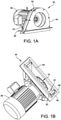
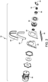
- blast media is fed from a feed spout 54 into a rotating impeller 52, which is driven by a motor 56.
- blast media particles are accelerated, giving rise to a centrifugal force that moves the particles in radial direction, away from the axis of the impeller 52.
- the particles now moving in a generally circular direction as well as outwards, move through impeller openings into a space between the impeller 52 and a control cage 58, still being carried by the movement of the impeller blades and the other particles.
- the control cage 58 functions to meter a consistent and appropriate amount of blast media onto the blades. As the blades rotate, the particles are moved along their lengths and accelerate until they reach the edges of the blades and are thrown from the edges of the blades.
- a lid 60 of the centrifugal blast wheel machine 50 may be provided. As shown, the housing walls 62, 64 are mounted on a mounting flange 66, with the left housing wall 62 being spaced from the right housing wall 64.
- the lid 60 may have a liner 20.
- a wheel assembly generally indicated at 68 having a plurality of blades is further provided to throw blast media introduced into the wheel assembly to treat the work piece.
- the arrangement is such that the impeller 52 is positioned about an axis of the wheel assembly 68, with the impeller 52 having a media inlet at one end adapted to receive blast media and a plurality of impeller media outlets constructed and arranged to allow egress of blast media upon rotation of the impeller 52.
- the control cage 58 surrounds the impeller 52 and has a cage media outlet adapted for passage of blast media to the leading edges of the blades.
- the motor 56 is coupled to the impeller 52 to drive the rotation of the impeller 52 and the wheel assembly 68.
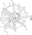
- FIG. 3 is a section view of a wheel assembly 68 and impeller 52.
- the wheel assembly 68 includes a wheel disk 40. While only one wheel disk 40 is shown in FIG. 3 , the assembly 68 may also include a pair of wheel disks, as shown in, for example, FIGS. 4 and 5 .
- the second wheel disk may be positioned opposite to the first wheel disk 40 and may be spaced apart by a plurality of blades 10.
- the wheel assembly 68 of FIG. 3 further includes spacers 30 that aid in spacing apart the wheel disk 40 from other components of the machine 50.
- the wheel assembly 68 includes a plurality of blades, each generally indicated at 10. The blades 10, which alternatively may be referred to as vanes, aid in throwing blast media.
- Each blade 10 shown in FIG. 3 have a semi-curved shape as further discussed below with reference to FIG. 6A .
- Each blade 10 has a leading edge 11 positioned adjacent to a central hub 75 or central axis of the wheel assembly 68, where blast media is first received by the blade 10.
- Each blade 10 is releasably secured to the wheel disk 40.
- the wheel disk 40 includes a groove or slot in the side of the wheel disk 40 into which a portion of the blade 10 slides (as shown, for example, in FIG. 4 ). In this manner, each blade 10 is fitted to the wheel disk 40.
- Each blade 10 may include one or two side rails 19 positioned along the length of the blade 10.
- the side rail 19 is configured to fit within the groove of the wheel disk 40, and secure the position of the blade 10 with respect to the wheel disk 40.
- Blade widths can vary, generally from 2 inches to 5 inches (50mm to 112mm), but other widths outside of this range also fall within the scope of this disclosure.
- Blade lengths can vary as well, generally from 3 inches to 7 inches (75mm to 180mm), but other lengths outside of this range also fall within the scope of this disclosure.
- Blade length may also be referred to in terms of a complete wheel diameter. Wheel diameters can vary, generally from 10 inches to 26 inches, but other diameters outside of this range also fall within the scope of this disclosure.
- FIG. 4 illustrates a bare wheel assembly generally indicated at 67 having wheel disks 40, 42 separated by spacers 30.
- the wheel disks 40, 42 have grooves 44, 46, respectively, formed therein, which receive the blades.
- the bare wheel assembly 67 includes the first wheel disk 40 having a first side 41, in which the first plurality of grooves 44 are defined. Each groove 44 is shaped to receive a blade.
- the bare wheel assembly 67 includes the second wheel disk 42 spaced apart from the first wheel disk 40 by spacers 30, which are secured to the first and second wheel disks in a suitable manner.
- the second wheel disk 42 has a second side 43, facing the first side 41 of the first wheel disk 40.
- the second plurality of grooves 46 are defined in the second side 43 of the second wheel disk 42.
- the first set of grooves 44 face and are aligned with corresponding grooves 46 from the second set of grooves.
- FIG. 5 illustrates the wheel assembly 67 having blades 10 inserted in each pair of grooves 44, 46.
- each of the grooves 44 on the first wheel disk 40 receives the blade 10, and in particular, receives a side rail 19 of the blade.
- Each of the grooves 46 on the second wheel disk 42 receives the blade 10, and in particular, receives a side rail 21 of the blade.
- the blades 10 are positioned so that the leading edge 11 is proximate the central hub 75, with the trailing edge 15 extending radially outwardly.
- FIG. 6A illustrates a side view of a blade 10 that is semi-curved.
- a leading edge 11 is affixed to a wheel disk 40 of a wheel assembly 68. Opposite the leading edge 11 is a trailing edge 15 where the abrasive material exits the blade 10 during operation.
- Blade 10 has a top surface 13 that faces the direction of the rotation of blade 10 and that receives the abrasive material.
- Blade 10 has a bottom surface 12 on the face opposite to that of the top surface 13.
- the blade 10 comprises a curved portion 16 that extends from the leading edge 11.
- the curved portion 16 ends at straight portion 17 which extends from the trailing edge 15.
- the curved portion 16 When attached to a wheel assembly, the curved portion 16 is positioned adjacent a central hub of the wheel assembly, and the straight portion 17 is integrally formed with the curved portion 16 extending radially outwardly from the wheel assembly 68.
- the angle theta 20 measures an angle formed between the trailing edge 15 and the leading edge 11. More specifically, as shown in FIG. 6B , the angle theta 20 measures the angle between hypothetical line 37, which corresponds to the orientation of blade at the trailing edge 15, and hypothetical line 35, which is tangent to the surface of the blade at the leading edge 11.
- the angle formed may be between 105° and 145°. Alternatively the angle formed may be between 120° and 130°.
- the blade includes two distinct geometries, a curved portion and a straight portion, each providing certain advantages. Different geometries at different locations within the blade perform specific functions in regards to hot spot, velocities, and abrasive consumption.
- the blade geometry proximate the leading edge 11 controls the abrasive consumption.
- the blade geometry proximate the trailing edge 15 controls the velocity of the abrasive.
- a semi-curved blade having a curved portion 16 proximate the leading edge 11 and a straight portion 17 proximate the trailing edge 15 achieves a reduced abrasive consumption without decreasing blade life from wear, while increasing abrasive velocities.
- Such a geometry aids in reducing a significant cost in the operation of a blast wheel - abrasive consumption.
- the curved portion 16 may extend for one half the length of the blade, while the straight portion 17 extends for the other half of the blade.
- the disclosed blade design may reduce abrasive consumption without the unintended effects of increased abrasive acceleration or decreased blade life, as compared to conventionally designed blades. This blade design may therefore lead to reduced operating costs resulting from reduced abrasive consumption, without increasing operating costs associated with the expense of replacing blades whose blade life has been decreased.
- the initial curved shape in the curved portion 10 extending from the leading edge 11, may allow for a more gentle abrasive transition from the exit of the control cage 58 onto the blade 10, as compared to a traditional straight blade.
- Traditional straight blades act like a 'battering ram' in which the abrasive hits the blade at great force, and then bounces off the surface several times before properly sliding over the blade surface.
- the semi-curved blade 10 changes from a curved shape to a straight shape to reduce the 'acceleration curve' effect and to minimize the potential of over-accelerating the abrasive and, thus, the forces applied to the abrasive.
- the forces applied to the abrasive By reducing the forces applied to the abrasive, consumption of the abrasive may be reduced. Furthermore, by reducing the applied forces, blade life may also be extended, as the result of less wear.
- FIG. 7 illustrates a blade generally indicated at 110 having a grommet positioned along a side rail for forming a compression fit with the wheel disk of the wheel assembly.
- the blade 110 shows a top surface 140 for receiving blast media.
- a leading edge 120 and a trailing edge 130 are positioned at the opposite ends of the blade 110.
- On one side of the blade 110 is a side rail 150.
- On one side of the blade 110 is a side rail 170.
- the side rail 150 includes a recess in which a grommet 160 is positioned.
- the grommet 160 is designed to aid in forming a compression fit between the blade 110 and the wheel disk of the wheel assembly.
- the grommet 160 may be made of any material suitable for providing sufficient friction to aid in creating a compression fit.
- the grommet 160 may be a rubber grommet 160.
- the casted recess of the side rail 150 may be round with no sharp corners with a minimum radius of 5° to prevent stress risers and cracking.
- the grommet plug 160 is inserted either manually or by automated process into the recess.
- the side rail 150 having a grommet 160 could function with any desired blade geometry.
- Alternative embodiments to that shown in FIG. 7 include a blade 110 having only a single side rail 150 with a grommet 160, as well as a blade 110 having a grommet 160 positioned in the second side rail 170, as well.
- the method includes providing a centrifugal blast wheel machine having a wheel assembly.
- the wheel assembly includes a wheel disk with a groove, and a first blade.
- the first blade has a side rail extending along the length of the blade.
- the side rail has a recess, in which a grommet is positioned.
- the blade is positioned in the groove of the wheel disk, secured by a compression fit between the grommet and the wheel disk.
- the blade is inserted into a groove in the wheel disk of the wheel assembly, where the grommet comes into contact with the wheel disk. From a tapered design, a compression fit is created between the rubber grommet and the wheel disk of the wheel assembly. A plurality of blades may be positioned in the wheel disk in this manner.
- the original blade or blades are removed.
- the blade may be removed by applying a force to the blade sufficient to overcome the compression fit. For example, a simple tap on the blade may be sufficient to free the blade.
- the grommet can also be removed by use of a simple tool such as pliers or a screw driver. By providing easy removal of the grommet, the grommet and casting can be recycled separately, thus providing an environmentally friendly element to the device.
- a different new or refurbished blade is then inserted into the groove.
- the new blade may include all the features of the first blade, including the grommet positioned in the recess of the side rail.
- the new blade is secured in the groove by compression fit between the grommet and the wheel disk. In this manner all blades of the wheel disk can be simply and easily replaced when maintenance is required.
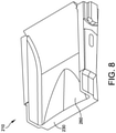
- FIG. 8 illustrates an alternative geometry for the semi-curved blade 210 incorporating a convex tip 260 proximate the trailing edge 230.
- a more detailed description of the convex tip 260 may be found in U.S. Patent No. 6,764,390 .
Landscapes
- Engineering & Computer Science (AREA)
- Mechanical Engineering (AREA)
- Structures Of Non-Positive Displacement Pumps (AREA)
- Polishing Bodies And Polishing Tools (AREA)
- Turbine Rotor Nozzle Sealing (AREA)
Description
- The present disclosure relates to 2. a centrifugal blast wheel machine and more particularly to blades for a centrifugal blast wheel machine and to a method of maintaining a centrifugal blast wheel machine.
- Centrifugal blast wheel machines generally include a rotatable hub to which is mounted a disk or a pair of spaced disks which carry radially extending blades. Particulate matter is discharged from a center of the wheel disk onto rotating surfaces of the blades, which propel the particulate matter against surfaces of a work piece to be cleaned or treated. Specifically, blast media is fed from a feed spout into a rotating impeller situated within a control cage at the center of the blast wheel. The media is fed from the impeller, through an opening in a control cage and onto leading edges of the rotating blades. The media travels along top surfaces of the blades and is thrown from trailing edges of the blades at the work piece surfaces to be treated. An example of such a centrifugal blast wheel machine is shown in the UK patent application
GB2152411A - Operating and properly maintaining a blast wheel can incur multiple ongoing expenses. For example, a cost associated with supplying blast media is one such expense. Another example is a cost associated with maintaining the blast wheel by replacing blades that have become worn down.
- According to an aspect of the invention, there is provided a centrifugal blast wheel machine as defined in claim 1. The centrifugal blast wheel machine comprises a housing and a wheel assembly coupled to the housing. The wheel assembly has a plurality of blades configured to throw blast media introduced into the wheel assembly against a work piece. Each blade of the plurality of blades includes a curved portion positioned adjacent a central hub of the wheel assembly, and a straight portion integrally formed with the curved portion extending radially outwardly from the wheel assembly.
- According to certain embodiments of the centrifugal blast wheel machine, each blade of the plurality of blades may have a first edge proximate the curved portion, and a second edge proximate the straight portion.
- The wheel assembly includes a first wheel disk with a first side and a first plurality of grooves in the first side. Each blade includes a first side rail extending along the blade, the first side rail having a first recess, and a first grommet positioned in the first recess. Each groove is configured to receive a corresponding blade of the plurality of blades. The corresponding blade is secured in place through a compression fit between the first side of the first wheel disk and the first grommet of the corresponding blade.
- According to certain embodiments of the centrifugal blast wheel machine, the first side rail may be tapered to aid in creating the compression fit. Each of the blades further comprises a second side rail extending along the blade, the second side rail being opposite the first side rail. According to certain embodiments of the centrifugal blast wheel machine, the second side rail may comprise a second recess and a second grommet positioned in the second recess. According to certain embodiments of the centrifugal blast wheel machine, the wheel assembly further may include a second wheel disk having a second side and a second plurality of grooves in the second side, the second side of the second wheel disk being spaced apart from the first side of the first wheel disk.
- According to certain embodiments of the centrifugal blast wheel machine, each groove of the first plurality of grooves and each groove of the second plurality of grooves may be configured to receive a corresponding blade from the plurality of blades, the corresponding blade being secured in place through compression fit between the first side of the first wheel disk and the first grommet of the corresponding blade and between the second side of the second wheel disk and the second grommet of the corresponding blade. According to certain embodiments of the centrifugal blast wheel machine, each of the first side rail and the second side rail may be tapered to aid in forming the compression fit. According to certain embodiments of the centrifugal blast wheel machine, the first grommet and the first recess may be configured to allow removal of the first grommet from the first recess at an end of a service life of the blade. According to certain embodiments of the centrifugal blast wheel machine, each of the first grommet and the first recess may be rounded.
- According to another aspect of the invention, there is provided a method of maintaining a centrifugal blast wheel machine, as defined in
claim 9. - According to certain embodiments of the method, removing the first blade from the wheel disk may comprise applying a force to the first blade sufficient to overcome the compression fit between the first grommet and the wheel disk. According to certain embodiments of the method, the method further may comprise removing the first grommet from the first blade after removing the first blade from the wheel disk.
- The accompanying drawings are not intended to be drawn to scale. In the drawings, each identical or nearly identical component that is illustrated in various figures is represented by a like numeral. For purposes of clarity, not every component may be labeled in every drawing. In the drawings:
-
FIG. 1A is a perspective view of a portion of a centrifugal blast wheel machine; -
FIG. 1B is another perspective view of a portion of a centrifugal blast wheel machine; -
FIG. 2 is an exploded perspective view of a centrifugal blast wheel machine; -
FIG. 3 is a perspective view of a wheel assembly of the centrifugal blast wheel machine having a side removed to reveal an interior of the wheel assembly; -
FIG. 4 is a perspective cross-sectional view of a bare wheel assembly with exposed grooves; -
FIG. 5 is a perspective cross-sectional view of a wheel assembly with inserted blades; -
FIG. 6A is a cross-sectional view showing an embodiment of a semi-curved blade; -
FIG. 6B is a cross-sectional view showing an embodiment of a semi-curved blade; -
FIG. 7 is a perspective view of an embodiment of a blade; and -
FIG. 8 is a perspective view of an embodiment of a blade. - For the purposes of illustration only, and not to limit the generality, the present disclosure will now be described in detail with reference to the accompanying figures. This disclosure is not limited in its application to the details of construction and the arrangement of components set forth in the following description or illustrated in the drawings. The principles set forth in this disclosure are capable of other embodiments and of being practiced or carried out in various ways. Also the phraseology and terminology used herein is for the purpose of description and should not be regarded as limiting. The use of "including," "comprising," "having," "containing," "involving," and variations thereof herein, is meant to encompass the items listed thereafter and equivalents thereof as well as additional items.
- The present disclosure is directed to blades for a centrifugal blast wheel machine.
- Specifically, the present disclosure is directed to blades designed to facilitate safer and easier replacement of the blade within the blast wheel and to blades designed to lower abrasive consumption. The present disclosure describes a blade insert to hold the blade during installation and a semi-curved blade for abrasive reduction.
- Referring to the drawings, the operation of a centrifugal blast wheel machine, generally indicated at 50, can be understood by reference to
FIGS. 1A, 1B , and2 . As shown, blast media is fed from afeed spout 54 into a rotatingimpeller 52, which is driven by amotor 56. By contact with the rotating impeller blades (as well as with other particles of media already in the impeller 52), blast media particles are accelerated, giving rise to a centrifugal force that moves the particles in radial direction, away from the axis of theimpeller 52. The particles, now moving in a generally circular direction as well as outwards, move through impeller openings into a space between theimpeller 52 and acontrol cage 58, still being carried by the movement of the impeller blades and the other particles. - When the particles have passed though the impeller openings, rotational and centrifugal forces move the particles onto edges of the blades. The
control cage 58 functions to meter a consistent and appropriate amount of blast media onto the blades. As the blades rotate, the particles are moved along their lengths and accelerate until they reach the edges of the blades and are thrown from the edges of the blades. - A
lid 60 of the centrifugalblast wheel machine 50 may be provided. As shown, thehousing walls flange 66, with theleft housing wall 62 being spaced from theright housing wall 64. Thelid 60 may have aliner 20. - A wheel assembly generally indicated at 68 having a plurality of blades is further provided to throw blast media introduced into the wheel assembly to treat the work piece. The arrangement is such that the
impeller 52 is positioned about an axis of thewheel assembly 68, with theimpeller 52 having a media inlet at one end adapted to receive blast media and a plurality of impeller media outlets constructed and arranged to allow egress of blast media upon rotation of theimpeller 52. Thecontrol cage 58 surrounds theimpeller 52 and has a cage media outlet adapted for passage of blast media to the leading edges of the blades. As mentioned above, themotor 56 is coupled to theimpeller 52 to drive the rotation of theimpeller 52 and thewheel assembly 68. -
FIG. 3 is a section view of awheel assembly 68 andimpeller 52. Thewheel assembly 68 includes awheel disk 40. While only onewheel disk 40 is shown inFIG. 3 , theassembly 68 may also include a pair of wheel disks, as shown in, for example,FIGS. 4 and5 . The second wheel disk may be positioned opposite to thefirst wheel disk 40 and may be spaced apart by a plurality ofblades 10. Thewheel assembly 68 ofFIG. 3 further includesspacers 30 that aid in spacing apart thewheel disk 40 from other components of themachine 50. Thewheel assembly 68 includes a plurality of blades, each generally indicated at 10. Theblades 10, which alternatively may be referred to as vanes, aid in throwing blast media. - The
blades 10 shown inFIG. 3 have a semi-curved shape as further discussed below with reference toFIG. 6A . Eachblade 10 has aleading edge 11 positioned adjacent to acentral hub 75 or central axis of thewheel assembly 68, where blast media is first received by theblade 10. At the opposite end of theblade 10, there is a trailingedge 15, from which the blast media is thrown onto a work piece. Eachblade 10 is releasably secured to thewheel disk 40. In one embodiment, thewheel disk 40 includes a groove or slot in the side of thewheel disk 40 into which a portion of theblade 10 slides (as shown, for example, inFIG. 4 ). In this manner, eachblade 10 is fitted to thewheel disk 40. Eachblade 10 may include one or twoside rails 19 positioned along the length of theblade 10. Theside rail 19 is configured to fit within the groove of thewheel disk 40, and secure the position of theblade 10 with respect to thewheel disk 40. Blade widths can vary, generally from 2 inches to 5 inches (50mm to 112mm), but other widths outside of this range also fall within the scope of this disclosure. Blade lengths can vary as well, generally from 3 inches to 7 inches (75mm to 180mm), but other lengths outside of this range also fall within the scope of this disclosure. Blade length may also be referred to in terms of a complete wheel diameter. Wheel diameters can vary, generally from 10 inches to 26 inches, but other diameters outside of this range also fall within the scope of this disclosure. -
FIG. 4 illustrates a bare wheel assembly generally indicated at 67 havingwheel disks spacers 30. As shown, thewheel disks grooves bare wheel assembly 67 includes thefirst wheel disk 40 having afirst side 41, in which the first plurality ofgrooves 44 are defined. Eachgroove 44 is shaped to receive a blade. Thebare wheel assembly 67 includes thesecond wheel disk 42 spaced apart from thefirst wheel disk 40 byspacers 30, which are secured to the first and second wheel disks in a suitable manner. Thesecond wheel disk 42 has asecond side 43, facing thefirst side 41 of thefirst wheel disk 40. The second plurality ofgrooves 46 are defined in thesecond side 43 of thesecond wheel disk 42. The first set ofgrooves 44 face and are aligned withcorresponding grooves 46 from the second set of grooves. When blades are inserted to thebare wheel assembly 67, each blade is received by a corresponding pair ofgrooves -
FIG. 5 illustrates thewheel assembly 67 havingblades 10 inserted in each pair ofgrooves FIG. 5 , each of thegrooves 44 on thefirst wheel disk 40 receives theblade 10, and in particular, receives aside rail 19 of the blade. Each of thegrooves 46 on thesecond wheel disk 42 receives theblade 10, and in particular, receives aside rail 21 of the blade. In one embodiment, theblades 10 are positioned so that the leadingedge 11 is proximate thecentral hub 75, with the trailingedge 15 extending radially outwardly. -
FIG. 6A illustrates a side view of ablade 10 that is semi-curved. A leadingedge 11 is affixed to awheel disk 40 of awheel assembly 68. Opposite the leadingedge 11 is a trailingedge 15 where the abrasive material exits theblade 10 during operation.Blade 10 has atop surface 13 that faces the direction of the rotation ofblade 10 and that receives the abrasive material.Blade 10 has abottom surface 12 on the face opposite to that of thetop surface 13. Theblade 10 comprises acurved portion 16 that extends from the leadingedge 11. Thecurved portion 16 ends atstraight portion 17 which extends from the trailingedge 15. When attached to a wheel assembly, thecurved portion 16 is positioned adjacent a central hub of the wheel assembly, and thestraight portion 17 is integrally formed with thecurved portion 16 extending radially outwardly from thewheel assembly 68. - One measure of the curvature of the
blade 10 is indicated by theangle theta 20. Theangle theta 20 measures an angle formed between the trailingedge 15 and the leadingedge 11. More specifically, as shown inFIG. 6B , theangle theta 20 measures the angle betweenhypothetical line 37, which corresponds to the orientation of blade at the trailingedge 15, andhypothetical line 35, which is tangent to the surface of the blade at theleading edge 11. For thesemi-curved blade 10, the angle formed may be between 105° and 145°. Alternatively the angle formed may be between 120° and 130°. - The blade includes two distinct geometries, a curved portion and a straight portion, each providing certain advantages. Different geometries at different locations within the blade perform specific functions in regards to hot spot, velocities, and abrasive consumption. The blade geometry proximate the
leading edge 11 controls the abrasive consumption. The blade geometry proximate the trailingedge 15 controls the velocity of the abrasive. - A semi-curved blade having a
curved portion 16 proximate theleading edge 11 and astraight portion 17 proximate the trailingedge 15 achieves a reduced abrasive consumption without decreasing blade life from wear, while increasing abrasive velocities. Such a geometry aids in reducing a significant cost in the operation of a blast wheel - abrasive consumption. In certain embodiments, not part of the present invention, thecurved portion 16 may extend for one half the length of the blade, while thestraight portion 17 extends for the other half of the blade. - The disclosed blade design may reduce abrasive consumption without the unintended effects of increased abrasive acceleration or decreased blade life, as compared to conventionally designed blades. This blade design may therefore lead to reduced operating costs resulting from reduced abrasive consumption, without increasing operating costs associated with the expense of replacing blades whose blade life has been decreased.
- The initial curved shape in the
curved portion 10 extending from the leadingedge 11, may allow for a more gentle abrasive transition from the exit of thecontrol cage 58 onto theblade 10, as compared to a traditional straight blade. Traditional straight blades act like a 'battering ram' in which the abrasive hits the blade at great force, and then bounces off the surface several times before properly sliding over the blade surface. - Unlike traditional full curved blades, the
semi-curved blade 10 changes from a curved shape to a straight shape to reduce the 'acceleration curve' effect and to minimize the potential of over-accelerating the abrasive and, thus, the forces applied to the abrasive. By reducing the forces applied to the abrasive, consumption of the abrasive may be reduced. Furthermore, by reducing the applied forces, blade life may also be extended, as the result of less wear. -
FIG. 7 illustrates a blade generally indicated at 110 having a grommet positioned along a side rail for forming a compression fit with the wheel disk of the wheel assembly. Theblade 110 shows atop surface 140 for receiving blast media. Aleading edge 120 and a trailingedge 130 are positioned at the opposite ends of theblade 110. On one side of theblade 110 is aside rail 150. On one side of theblade 110 is aside rail 170. Theside rail 150 includes a recess in which agrommet 160 is positioned. Thegrommet 160 is designed to aid in forming a compression fit between theblade 110 and the wheel disk of the wheel assembly. Thegrommet 160 may be made of any material suitable for providing sufficient friction to aid in creating a compression fit. For example, thegrommet 160 may be arubber grommet 160. The casted recess of theside rail 150 may be round with no sharp corners with a minimum radius of 5° to prevent stress risers and cracking. Thegrommet plug 160 is inserted either manually or by automated process into the recess. - While the
blade 110 shown inFIG. 7 is a semi-curved blade, theside rail 150 having agrommet 160 could function with any desired blade geometry. Alternative embodiments to that shown inFIG. 7 include ablade 110 having only asingle side rail 150 with agrommet 160, as well as ablade 110 having agrommet 160 positioned in thesecond side rail 170, as well. - Inclusion of a grommet aids in installation and removal of blades into and from a wheel assembly. Methods for maintaining a centrifugal blast wheel machine are disclosed herein. The method includes providing a centrifugal blast wheel machine having a wheel assembly. The wheel assembly includes a wheel disk with a groove, and a first blade. The first blade has a side rail extending along the length of the blade. The side rail has a recess, in which a grommet is positioned. The blade is positioned in the groove of the wheel disk, secured by a compression fit between the grommet and the wheel disk. To install the blade having a grommet in the side rail, the blade is inserted into a groove in the wheel disk of the wheel assembly, where the grommet comes into contact with the wheel disk. From a tapered design, a compression fit is created between the rubber grommet and the wheel disk of the wheel assembly. A plurality of blades may be positioned in the wheel disk in this manner.
- When the wheel assembly requires maintenance because, for example, a blade or multiple blades require replacement, the original blade or blades are removed. The blade may be removed by applying a force to the blade sufficient to overcome the compression fit. For example, a simple tap on the blade may be sufficient to free the blade. Once the blade is removed, the grommet can also be removed by use of a simple tool such as pliers or a screw driver. By providing easy removal of the grommet, the grommet and casting can be recycled separately, thus providing an environmentally friendly element to the device.
- A different new or refurbished blade is then inserted into the groove. The new blade may include all the features of the first blade, including the grommet positioned in the recess of the side rail. The new blade is secured in the groove by compression fit between the grommet and the wheel disk. In this manner all blades of the wheel disk can be simply and easily replaced when maintenance is required.
-
FIG. 8 illustrates an alternative geometry for thesemi-curved blade 210 incorporating aconvex tip 260 proximate the trailingedge 230. A more detailed description of theconvex tip 260 may be found inU.S. Patent No. 6,764,390 . - Having thus described several aspects of at least one embodiment of this disclosure, it is to be appreciated various alterations, modifications, and improvements will readily occur to those skilled in the art. Such alterations, modifications, and improvements are intended to be part of this disclosure, and are intended to be within the scope of the disclosure. Accordingly, the foregoing description and drawings are by way of example only.
Claims (11)
- A centrifugal blast wheel machine (50) comprising:a housing; anda wheel assembly (67, 68) coupled to the housing, the wheel assembly including:a first wheel disk (40) with a first side (41) and a first plurality of grooves (44) in the first side; anda plurality of blades (10, 110, 210) configured to throw blast media introduced intothe wheel assembly against a work piece, each blade including:a top surface (13, 140) to receiving blast media;a first side rail (19, 150) extending along a first side of the blade, the first side rail having a first recess; anda second side rail (21, 170) extending along a second side of the blade, the second side rail being opposite the first side rail;wherein each groove is configured to receive a corresponding blade of the plurality of blades,
characterised in that:- each blade includes a curved portion (16) positioned adjacent a central hub of the wheel assembly and a straight portion (17) integrally formed with the curved portion extending radially outwardly from the wheel assembly; and in that:- the wheel assembly further includes a first grommet (160) positioned in the first recess, the grommet of the corresponding blade being configured to create a compression fit between the corresponding blade and the first side of the first wheel disk to secure the corresponding blade in place. - The centrifugal blast wheel machine of claim 1, wherein the second side rail including a second recess and a second grommet positioned in the second recess.
- The centrifugal blast wheel machine of claim 2, wherein the wheel assembly further includes a second wheel disk having a second side and a second plurality of grooves in the second side, the second side of the second wheel disk being spaced apart from the first side of the first wheel disk.
- The centrifugal blast wheel machine of claim 3, wherein each groove of the first plurality of grooves and each groove of the second plurality of grooves are configured to receive a corresponding blade from the plurality of blades, the corresponding blade being secured in place through compression fit between the first side of the first wheel disk and the first grommet of the corresponding blade and between the second side of the second wheel disk and the second grommet of the corresponding blade.
- The centrifugal blast wheel machine of claim 4, wherein at least one of the first side rail and the second side rail is tapered to aid in forming the compression fit.
- The centrifugal blast wheel machine of claim 1, wherein the first grommet and the first recess are configured to allow removal of the first grommet from the first recess at an end of a service life of the blade, wherein each of the first grommet and the first recess is rounded.
- The centrifugal blast wheel machine of claim 1, wherein each of the first grommet and the first recess is rounded.
- The centrifugal blast wheel machine of claim 1, wherein each blade of the plurality of blades has a first edge proximate the curved portion, and a second edge proximate the straight portion.
- A method of maintaining a centrifugal blast wheel machine (50) comprising:providing a centrifugal blast wheel machine having a wheel assembly, (67, 68) the wheel assembly (67, 68) including:a wheel disk (40) with a groove; (44) anda first blade 2. (10, 110, 210) having:a top surface (13, 140) to receive blast media;a curved portion (16) positioned adjacent a central hub of the wheel assembly;a straight portion (17) integrally formed with the curved portionextending radially outwardly from the wheel assembly;a first side rail (19, 150) extending along a first side of the first blade, the first side rail having a first recess;a second side rail (21, 170) extending along a second side of the blade,the second side rail being opposite the first side rail; and
a first grommet (160) positioned in the first recess, the first blade being secured in the groove by a compression fit between the first grommet and the wheel disk;removing the first blade from the wheel disk;inserting a second blade into the groove of the wheel disk, the second blade being identical to the first blade; andsecuring the second blade in the groove by compression fit between a first grommet of the second blade and the wheel disk. - The method of claim 9, wherein removing the first blade from the wheel disk comprises applying a force to the first blade sufficient to overcome the compression fit between the first grommet and the wheel disk.
- The method of claim 10, further comprising removing the first grommet from the first blade after removing the first blade from the wheel disk.
Priority Applications (1)
| Application Number | Priority Date | Filing Date | Title |
|---|---|---|---|
| PL14902531T PL3197638T3 (en) | 2014-09-25 | 2014-09-25 | Centrifugal blast wheel machine and method of maintaining a centrifugal blast wheel machine |
Applications Claiming Priority (1)
| Application Number | Priority Date | Filing Date | Title |
|---|---|---|---|
| PCT/US2014/057367 WO2016048319A1 (en) | 2014-09-25 | 2014-09-25 | Blade for centrifugal blast wheel machine and method of maintaining a centrifugal blast wheel machine |
Publications (3)
| Publication Number | Publication Date |
|---|---|
| EP3197638A1 EP3197638A1 (en) | 2017-08-02 |
| EP3197638A4 EP3197638A4 (en) | 2018-08-29 |
| EP3197638B1 true EP3197638B1 (en) | 2022-02-16 |
Family
ID=55581641
Family Applications (1)
| Application Number | Title | Priority Date | Filing Date |
|---|---|---|---|
| EP14902531.4A Active EP3197638B1 (en) | 2014-09-25 | 2014-09-25 | Centrifugal blast wheel machine and method of maintaining a centrifugal blast wheel machine |
Country Status (11)
| Country | Link |
|---|---|
| US (1) | US10384327B2 (en) |
| EP (1) | EP3197638B1 (en) |
| CN (1) | CN106715050A (en) |
| BR (1) | BR112017006031A2 (en) |
| CA (1) | CA2962359A1 (en) |
| ES (1) | ES2908847T3 (en) |
| MX (1) | MX2017003775A (en) |
| PL (1) | PL3197638T3 (en) |
| PT (1) | PT3197638T (en) |
| RU (1) | RU2709317C2 (en) |
| WO (1) | WO2016048319A1 (en) |
Families Citing this family (8)
| Publication number | Priority date | Publication date | Assignee | Title |
|---|---|---|---|---|
| CN107378797B (en) * | 2017-08-02 | 2023-08-18 | 常州泰盛机械设备有限公司 | Turntable type shot blasting machine |
| CN107378798B (en) * | 2017-08-02 | 2023-08-29 | 常州泰盛机械设备有限公司 | Shot blasting machine |
| US10335923B2 (en) * | 2017-08-23 | 2019-07-02 | Wheelabrator Group, Inc. | Centrifugal blade lock and release device for a blast wheel machine |
| US10155299B1 (en) * | 2017-08-23 | 2018-12-18 | Wheelabrator Group, Inc. | Impeller for a blast wheel machine |
| TWI758637B (en) * | 2019-09-11 | 2022-03-21 | 亞比斯創新科技股份有限公司 | Impeller structure and projection equipment |
| TWI709460B (en) * | 2019-09-12 | 2020-11-11 | 亞比斯包材工場股份有限公司 | Shot blasting machine and blade wheel assembly thereof |
| CN113351831B (en) * | 2021-05-06 | 2022-12-23 | 江山市通联泵业成套有限公司 | High-precision and integrally-formed water pump impeller |
| CN114505791B (en) * | 2022-03-22 | 2023-09-01 | 河海大学常州校区 | Impeller and impeller blade |
Family Cites Families (28)
| Publication number | Priority date | Publication date | Assignee | Title |
|---|---|---|---|---|
| US1996885A (en) * | 1932-03-23 | 1935-04-09 | Schemmann Walter | Centrifugal device for throwing abrasive |
| US2590576A (en) | 1934-05-17 | 1952-03-25 | Pangborn Corp | Abrading apparatus |
| US2204633A (en) | 1936-11-17 | 1940-06-18 | American Foundry Equip Co | Abrasive-throwing wheel |
| US2368664A (en) * | 1938-03-10 | 1945-02-06 | Pangborn Corp | Abrading apparatus |
| GB1003441A (en) * | 1963-04-18 | 1965-09-02 | Spencer & Halstead Ltd | Blades for the impellers of blast-cleaning machines |
| US3241266A (en) * | 1963-07-10 | 1966-03-22 | Pangborn Corp | Abrasive particle throwing wheel assembly |
| US3242615A (en) * | 1963-08-05 | 1966-03-29 | Pangborn Corp | Apparatus for widening the abrasive blast stream of abrasive blasting wheels |
| US3287858A (en) * | 1964-07-13 | 1966-11-29 | Pangborn Corp | Abrasive blasting wheel assembly |
| US3352064A (en) * | 1965-02-01 | 1967-11-14 | Wheelabrator Corp | Lock system for blasting-machine blades |
| US3348339A (en) * | 1965-05-24 | 1967-10-24 | Pangborn Corp | Abrasive blasting wheels and vanes |
| US3401489A (en) * | 1966-02-28 | 1968-09-17 | Evert H. Wern | Apparatus for airless blast finishing |
| US3678629A (en) * | 1970-03-19 | 1972-07-25 | Wheelabrator Frye Inc | Centrifugal blasting wheel and blade therefor |
| US3683556A (en) | 1970-04-13 | 1972-08-15 | Raymond M Leliaert | Centrifugal blasting wheel |
| US3785105A (en) | 1972-04-05 | 1974-01-15 | Wheelabrator Frye Inc | Centrifugal blasting wheel |
| US3872624A (en) | 1973-10-29 | 1975-03-25 | Carborundum Co | Curved vane for throwing wheels |
| CH559084A5 (en) | 1973-11-22 | 1975-02-28 | Fischer Ag Georg | |
| CH623769A5 (en) | 1977-11-17 | 1981-06-30 | Fischer Ag Georg | |
| US4249350A (en) * | 1979-01-15 | 1981-02-10 | Goff James R | Abrasive throwing wheel and improved blade assembly |
| US4395851A (en) * | 1981-02-03 | 1983-08-02 | Watts W David | Centrifugal abrasive blasting machine |
| GB8400627D0 (en) | 1984-01-11 | 1984-02-15 | Tilghman Wheelabrator Ltd | Centrifugal abrasive throwing wheels |
| DE19536723C2 (en) | 1995-09-30 | 1997-08-21 | Jost Dipl Ing Wadephul | Centrifugal wheel |
| US6126516A (en) | 1999-05-10 | 2000-10-03 | United States Filter Corporation | Centrifugal blasting apparatus |
| AU2001273016A1 (en) | 2000-10-02 | 2002-04-15 | Pangborn Corporation | Abrasive throwing wheel and improved blade assembly |
| DE10135845B4 (en) * | 2001-07-23 | 2004-09-30 | Schlick-Roto-Jet Maschinenbau Gmbh | A blast wheel |
| US6764390B2 (en) | 2001-11-28 | 2004-07-20 | International Surface Preparation Group, Inc. | Centrifugal throwing vane |
| DE10216351A1 (en) * | 2002-04-13 | 2003-10-23 | Damir Jankov | blower |
| DE102006058022B4 (en) | 2006-12-07 | 2009-12-17 | Horst-Dieter Schlick | Blower wheel for a jet device |
| EP2829360B1 (en) | 2013-07-19 | 2015-09-16 | Prefer - Equipamentos Para Decapagem, Lda. | Control cage for a shot blasting turbine and components |
-
2014
- 2014-09-25 PT PT149025314T patent/PT3197638T/en unknown
- 2014-09-25 MX MX2017003775A patent/MX2017003775A/en unknown
- 2014-09-25 RU RU2017114025A patent/RU2709317C2/en active
- 2014-09-25 WO PCT/US2014/057367 patent/WO2016048319A1/en not_active Ceased
- 2014-09-25 US US15/513,878 patent/US10384327B2/en active Active
- 2014-09-25 EP EP14902531.4A patent/EP3197638B1/en active Active
- 2014-09-25 CN CN201480082140.6A patent/CN106715050A/en active Pending
- 2014-09-25 CA CA2962359A patent/CA2962359A1/en not_active Abandoned
- 2014-09-25 ES ES14902531T patent/ES2908847T3/en active Active
- 2014-09-25 BR BR112017006031A patent/BR112017006031A2/en not_active Application Discontinuation
- 2014-09-25 PL PL14902531T patent/PL3197638T3/en unknown
Also Published As
| Publication number | Publication date |
|---|---|
| EP3197638A4 (en) | 2018-08-29 |
| BR112017006031A2 (en) | 2017-12-12 |
| CA2962359A1 (en) | 2016-03-31 |
| RU2017114025A3 (en) | 2018-10-25 |
| MX2017003775A (en) | 2017-06-29 |
| ES2908847T3 (en) | 2022-05-04 |
| RU2017114025A (en) | 2018-10-25 |
| CN106715050A (en) | 2017-05-24 |
| US20170304994A1 (en) | 2017-10-26 |
| EP3197638A1 (en) | 2017-08-02 |
| WO2016048319A1 (en) | 2016-03-31 |
| PT3197638T (en) | 2022-03-16 |
| US10384327B2 (en) | 2019-08-20 |
| PL3197638T3 (en) | 2022-04-19 |
| RU2709317C2 (en) | 2019-12-17 |
Similar Documents
| Publication | Publication Date | Title |
|---|---|---|
| US10384327B2 (en) | Blade for centrifugal blast wheel machine and method of maintaining a centrifugal blast wheel machine | |
| CA1138207A (en) | Bladed centrifugal blasting wheel | |
| KR102512923B1 (en) | Decanter centrifuge | |
| WO2017014767A1 (en) | Control cage for centrifugal blast wheel machine | |
| US10335923B2 (en) | Centrifugal blade lock and release device for a blast wheel machine | |
| EP1694465B1 (en) | Control cage for abrasive blast wheel | |
| JP4740950B2 (en) | Centrifugal nozzle and method and apparatus for inserting the nozzle into a centrifugal bowl | |
| US2708814A (en) | Centrifugal blasting wheel | |
| US20140038498A1 (en) | Blade and wheel plate for blast cleaning wheel and method of connecting a blade to the wheel plate | |
| US4480413A (en) | Bladed centrifugal blasting wheel | |
| US2204635A (en) | Centrifugal abrading machine | |
| EP3191259B1 (en) | Control cage assembly for centrifugal blast wheel machine | |
| HK1232491A1 (en) | Blade for centrifugal blast wheel machine and method of maintaining a centrifugal blast wheel machine | |
| US4203263A (en) | Slinging wheel for centrifugal jet machines | |
| EP3330002A1 (en) | Feeding unit for a centrifugal separator | |
| CN114007812B (en) | Impeller for shot blasting machine | |
| WO2017092806A1 (en) | Spring assembly to position liners in a blast wheel machine | |
| CN1972781A (en) | Impeller for feeding the blasting medium into the rotor | |
| RU2596569C1 (en) | Blast wheel | |
| CN101336150A (en) | Control frame, centrifugal projection device and centrifugal projection device for projecting abrasive particles | |
| HK40061095A (en) | Impeller for a blast wheel machine | |
| HK40061095B (en) | Impeller for a blast wheel machine |
Legal Events
| Date | Code | Title | Description |
|---|---|---|---|
| STAA | Information on the status of an ep patent application or granted ep patent |
Free format text: STATUS: THE INTERNATIONAL PUBLICATION HAS BEEN MADE |
|
| PUAI | Public reference made under article 153(3) epc to a published international application that has entered the european phase |
Free format text: ORIGINAL CODE: 0009012 |
|
| STAA | Information on the status of an ep patent application or granted ep patent |
Free format text: STATUS: REQUEST FOR EXAMINATION WAS MADE |
|
| 17P | Request for examination filed |
Effective date: 20170320 |
|
| AK | Designated contracting states |
Kind code of ref document: A1 Designated state(s): AL AT BE BG CH CY CZ DE DK EE ES FI FR GB GR HR HU IE IS IT LI LT LU LV MC MK MT NL NO PL PT RO RS SE SI SK SM TR |
|
| AX | Request for extension of the european patent |
Extension state: BA ME |
|
| DAX | Request for extension of the european patent (deleted) | ||
| RIC1 | Information provided on ipc code assigned before grant |
Ipc: B24C 5/06 20060101AFI20180316BHEP |
|
| A4 | Supplementary search report drawn up and despatched |
Effective date: 20180801 |
|
| RIC1 | Information provided on ipc code assigned before grant |
Ipc: B24C 5/06 20060101AFI20180726BHEP |
|
| GRAP | Despatch of communication of intention to grant a patent |
Free format text: ORIGINAL CODE: EPIDOSNIGR1 |
|
| STAA | Information on the status of an ep patent application or granted ep patent |
Free format text: STATUS: GRANT OF PATENT IS INTENDED |
|
| GRAJ | Information related to disapproval of communication of intention to grant by the applicant or resumption of examination proceedings by the epo deleted |
Free format text: ORIGINAL CODE: EPIDOSDIGR1 |
|
| GRAP | Despatch of communication of intention to grant a patent |
Free format text: ORIGINAL CODE: EPIDOSNIGR1 |
|
| INTG | Intention to grant announced |
Effective date: 20211014 |
|
| INTG | Intention to grant announced |
Effective date: 20211027 |
|
| GRAS | Grant fee paid |
Free format text: ORIGINAL CODE: EPIDOSNIGR3 |
|
| GRAA | (expected) grant |
Free format text: ORIGINAL CODE: 0009210 |
|
| STAA | Information on the status of an ep patent application or granted ep patent |
Free format text: STATUS: THE PATENT HAS BEEN GRANTED |
|
| AK | Designated contracting states |
Kind code of ref document: B1 Designated state(s): AL AT BE BG CH CY CZ DE DK EE ES FI FR GB GR HR HU IE IS IT LI LT LU LV MC MK MT NL NO PL PT RO RS SE SI SK SM TR |
|
| REG | Reference to a national code |
Ref country code: GB Ref legal event code: FG4D |
|
| REG | Reference to a national code |
Ref country code: CH Ref legal event code: EP |
|
| REG | Reference to a national code |
Ref country code: DE Ref legal event code: R096 Ref document number: 602014082551 Country of ref document: DE |
|
| REG | Reference to a national code |
Ref country code: AT Ref legal event code: REF Ref document number: 1468596 Country of ref document: AT Kind code of ref document: T Effective date: 20220315 |
|
| REG | Reference to a national code |
Ref country code: IE Ref legal event code: FG4D Ref country code: PT Ref legal event code: SC4A Ref document number: 3197638 Country of ref document: PT Date of ref document: 20220316 Kind code of ref document: T Free format text: AVAILABILITY OF NATIONAL TRANSLATION Effective date: 20220309 |
|
| REG | Reference to a national code |
Ref country code: ES Ref legal event code: FG2A Ref document number: 2908847 Country of ref document: ES Kind code of ref document: T3 Effective date: 20220504 |
|
| REG | Reference to a national code |
Ref country code: SE Ref legal event code: TRGR |
|
| REG | Reference to a national code |
Ref country code: LT Ref legal event code: MG9D |
|
| REG | Reference to a national code |
Ref country code: NL Ref legal event code: MP Effective date: 20220216 |
|
| REG | Reference to a national code |
Ref country code: AT Ref legal event code: MK05 Ref document number: 1468596 Country of ref document: AT Kind code of ref document: T Effective date: 20220216 |
|
| PG25 | Lapsed in a contracting state [announced via postgrant information from national office to epo] |
Ref country code: RS Free format text: LAPSE BECAUSE OF FAILURE TO SUBMIT A TRANSLATION OF THE DESCRIPTION OR TO PAY THE FEE WITHIN THE PRESCRIBED TIME-LIMIT Effective date: 20220216 Ref country code: NO Free format text: LAPSE BECAUSE OF FAILURE TO SUBMIT A TRANSLATION OF THE DESCRIPTION OR TO PAY THE FEE WITHIN THE PRESCRIBED TIME-LIMIT Effective date: 20220516 Ref country code: NL Free format text: LAPSE BECAUSE OF FAILURE TO SUBMIT A TRANSLATION OF THE DESCRIPTION OR TO PAY THE FEE WITHIN THE PRESCRIBED TIME-LIMIT Effective date: 20220216 Ref country code: LT Free format text: LAPSE BECAUSE OF FAILURE TO SUBMIT A TRANSLATION OF THE DESCRIPTION OR TO PAY THE FEE WITHIN THE PRESCRIBED TIME-LIMIT Effective date: 20220216 Ref country code: HR Free format text: LAPSE BECAUSE OF FAILURE TO SUBMIT A TRANSLATION OF THE DESCRIPTION OR TO PAY THE FEE WITHIN THE PRESCRIBED TIME-LIMIT Effective date: 20220216 Ref country code: BG Free format text: LAPSE BECAUSE OF FAILURE TO SUBMIT A TRANSLATION OF THE DESCRIPTION OR TO PAY THE FEE WITHIN THE PRESCRIBED TIME-LIMIT Effective date: 20220516 |
|
| PG25 | Lapsed in a contracting state [announced via postgrant information from national office to epo] |
Ref country code: LV Free format text: LAPSE BECAUSE OF FAILURE TO SUBMIT A TRANSLATION OF THE DESCRIPTION OR TO PAY THE FEE WITHIN THE PRESCRIBED TIME-LIMIT Effective date: 20220216 Ref country code: GR Free format text: LAPSE BECAUSE OF FAILURE TO SUBMIT A TRANSLATION OF THE DESCRIPTION OR TO PAY THE FEE WITHIN THE PRESCRIBED TIME-LIMIT Effective date: 20220517 Ref country code: FI Free format text: LAPSE BECAUSE OF FAILURE TO SUBMIT A TRANSLATION OF THE DESCRIPTION OR TO PAY THE FEE WITHIN THE PRESCRIBED TIME-LIMIT Effective date: 20220216 Ref country code: AT Free format text: LAPSE BECAUSE OF FAILURE TO SUBMIT A TRANSLATION OF THE DESCRIPTION OR TO PAY THE FEE WITHIN THE PRESCRIBED TIME-LIMIT Effective date: 20220216 |
|
| PG25 | Lapsed in a contracting state [announced via postgrant information from national office to epo] |
Ref country code: IS Free format text: LAPSE BECAUSE OF FAILURE TO SUBMIT A TRANSLATION OF THE DESCRIPTION OR TO PAY THE FEE WITHIN THE PRESCRIBED TIME-LIMIT Effective date: 20220617 |
|
| PG25 | Lapsed in a contracting state [announced via postgrant information from national office to epo] |
Ref country code: SM Free format text: LAPSE BECAUSE OF FAILURE TO SUBMIT A TRANSLATION OF THE DESCRIPTION OR TO PAY THE FEE WITHIN THE PRESCRIBED TIME-LIMIT Effective date: 20220216 Ref country code: SK Free format text: LAPSE BECAUSE OF FAILURE TO SUBMIT A TRANSLATION OF THE DESCRIPTION OR TO PAY THE FEE WITHIN THE PRESCRIBED TIME-LIMIT Effective date: 20220216 Ref country code: RO Free format text: LAPSE BECAUSE OF FAILURE TO SUBMIT A TRANSLATION OF THE DESCRIPTION OR TO PAY THE FEE WITHIN THE PRESCRIBED TIME-LIMIT Effective date: 20220216 Ref country code: EE Free format text: LAPSE BECAUSE OF FAILURE TO SUBMIT A TRANSLATION OF THE DESCRIPTION OR TO PAY THE FEE WITHIN THE PRESCRIBED TIME-LIMIT Effective date: 20220216 Ref country code: DK Free format text: LAPSE BECAUSE OF FAILURE TO SUBMIT A TRANSLATION OF THE DESCRIPTION OR TO PAY THE FEE WITHIN THE PRESCRIBED TIME-LIMIT Effective date: 20220216 |
|
| REG | Reference to a national code |
Ref country code: DE Ref legal event code: R097 Ref document number: 602014082551 Country of ref document: DE |
|
| PG25 | Lapsed in a contracting state [announced via postgrant information from national office to epo] |
Ref country code: AL Free format text: LAPSE BECAUSE OF FAILURE TO SUBMIT A TRANSLATION OF THE DESCRIPTION OR TO PAY THE FEE WITHIN THE PRESCRIBED TIME-LIMIT Effective date: 20220216 |
|
| PLBE | No opposition filed within time limit |
Free format text: ORIGINAL CODE: 0009261 |
|
| STAA | Information on the status of an ep patent application or granted ep patent |
Free format text: STATUS: NO OPPOSITION FILED WITHIN TIME LIMIT |
|
| 26N | No opposition filed |
Effective date: 20221117 |
|
| PG25 | Lapsed in a contracting state [announced via postgrant information from national office to epo] |
Ref country code: SI Free format text: LAPSE BECAUSE OF FAILURE TO SUBMIT A TRANSLATION OF THE DESCRIPTION OR TO PAY THE FEE WITHIN THE PRESCRIBED TIME-LIMIT Effective date: 20220216 |
|
| PG25 | Lapsed in a contracting state [announced via postgrant information from national office to epo] |
Ref country code: MC Free format text: LAPSE BECAUSE OF FAILURE TO SUBMIT A TRANSLATION OF THE DESCRIPTION OR TO PAY THE FEE WITHIN THE PRESCRIBED TIME-LIMIT Effective date: 20220216 |
|
| REG | Reference to a national code |
Ref country code: CH Ref legal event code: PL |
|
| GBPC | Gb: european patent ceased through non-payment of renewal fee |
Effective date: 20220925 |
|
| REG | Reference to a national code |
Ref country code: BE Ref legal event code: MM Effective date: 20220930 |
|
| REG | Reference to a national code |
Ref country code: GB Ref legal event code: S28 Free format text: APPLICATION FILED |
|
| PG25 | Lapsed in a contracting state [announced via postgrant information from national office to epo] |
Ref country code: LU Free format text: LAPSE BECAUSE OF NON-PAYMENT OF DUE FEES Effective date: 20220925 |
|
| P01 | Opt-out of the competence of the unified patent court (upc) registered |
Effective date: 20230525 |
|
| PG25 | Lapsed in a contracting state [announced via postgrant information from national office to epo] |
Ref country code: LI Free format text: LAPSE BECAUSE OF NON-PAYMENT OF DUE FEES Effective date: 20220930 Ref country code: IE Free format text: LAPSE BECAUSE OF NON-PAYMENT OF DUE FEES Effective date: 20220925 Ref country code: CH Free format text: LAPSE BECAUSE OF NON-PAYMENT OF DUE FEES Effective date: 20220930 |
|
| REG | Reference to a national code |
Ref country code: GB Ref legal event code: S28 Free format text: RESTORATION ALLOWED Effective date: 20230831 |
|
| PG25 | Lapsed in a contracting state [announced via postgrant information from national office to epo] |
Ref country code: BE Free format text: LAPSE BECAUSE OF NON-PAYMENT OF DUE FEES Effective date: 20220930 |
|
| PG25 | Lapsed in a contracting state [announced via postgrant information from national office to epo] |
Ref country code: GB Free format text: LAPSE BECAUSE OF NON-PAYMENT OF DUE FEES Effective date: 20220925 |
|
| PG25 | Lapsed in a contracting state [announced via postgrant information from national office to epo] |
Ref country code: HU Free format text: LAPSE BECAUSE OF FAILURE TO SUBMIT A TRANSLATION OF THE DESCRIPTION OR TO PAY THE FEE WITHIN THE PRESCRIBED TIME-LIMIT; INVALID AB INITIO Effective date: 20140925 |
|
| PG25 | Lapsed in a contracting state [announced via postgrant information from national office to epo] |
Ref country code: CY Free format text: LAPSE BECAUSE OF FAILURE TO SUBMIT A TRANSLATION OF THE DESCRIPTION OR TO PAY THE FEE WITHIN THE PRESCRIBED TIME-LIMIT Effective date: 20220216 |
|
| PG25 | Lapsed in a contracting state [announced via postgrant information from national office to epo] |
Ref country code: MK Free format text: LAPSE BECAUSE OF FAILURE TO SUBMIT A TRANSLATION OF THE DESCRIPTION OR TO PAY THE FEE WITHIN THE PRESCRIBED TIME-LIMIT Effective date: 20220216 |
|
| PG25 | Lapsed in a contracting state [announced via postgrant information from national office to epo] |
Ref country code: MT Free format text: LAPSE BECAUSE OF FAILURE TO SUBMIT A TRANSLATION OF THE DESCRIPTION OR TO PAY THE FEE WITHIN THE PRESCRIBED TIME-LIMIT Effective date: 20220216 |
|
| PGFP | Annual fee paid to national office [announced via postgrant information from national office to epo] |
Ref country code: PT Payment date: 20250725 Year of fee payment: 12 |
|
| PGFP | Annual fee paid to national office [announced via postgrant information from national office to epo] |
Ref country code: DE Payment date: 20250825 Year of fee payment: 12 |
|
| PGFP | Annual fee paid to national office [announced via postgrant information from national office to epo] |
Ref country code: PL Payment date: 20250919 Year of fee payment: 12 Ref country code: IT Payment date: 20250821 Year of fee payment: 12 Ref country code: TR Payment date: 20250731 Year of fee payment: 12 |
|
| PGFP | Annual fee paid to national office [announced via postgrant information from national office to epo] |
Ref country code: GB Payment date: 20250704 Year of fee payment: 12 |
|
| PGFP | Annual fee paid to national office [announced via postgrant information from national office to epo] |
Ref country code: FR Payment date: 20250722 Year of fee payment: 12 |
|
| PGFP | Annual fee paid to national office [announced via postgrant information from national office to epo] |
Ref country code: SE Payment date: 20250717 Year of fee payment: 12 |
|
| PGFP | Annual fee paid to national office [announced via postgrant information from national office to epo] |
Ref country code: CZ Payment date: 20250722 Year of fee payment: 12 |
|
| PGFP | Annual fee paid to national office [announced via postgrant information from national office to epo] |
Ref country code: ES Payment date: 20251126 Year of fee payment: 12 |