EP3197409B1 - Systems for lenticular laser incision - Google Patents
Systems for lenticular laser incision Download PDFInfo
- Publication number
- EP3197409B1 EP3197409B1 EP15777805.1A EP15777805A EP3197409B1 EP 3197409 B1 EP3197409 B1 EP 3197409B1 EP 15777805 A EP15777805 A EP 15777805A EP 3197409 B1 EP3197409 B1 EP 3197409B1
- Authority
- EP
- European Patent Office
- Prior art keywords
- lens
- laser system
- ophthalmic surgical
- incision
- surgical laser
- Prior art date
- Legal status (The legal status is an assumption and is not a legal conclusion. Google has not performed a legal analysis and makes no representation as to the accuracy of the status listed.)
- Active
Links
- 210000004087 cornea Anatomy 0.000 claims description 57
- 230000002093 peripheral effect Effects 0.000 claims description 13
- 238000000034 method Methods 0.000 description 43
- 238000002224 dissection Methods 0.000 description 39
- 238000012937 correction Methods 0.000 description 23
- 239000000463 material Substances 0.000 description 20
- 230000004305 hyperopia Effects 0.000 description 17
- 201000006318 hyperopia Diseases 0.000 description 17
- 206010020675 Hypermetropia Diseases 0.000 description 16
- 238000000605 extraction Methods 0.000 description 15
- 230000009471 action Effects 0.000 description 14
- 238000003860 storage Methods 0.000 description 12
- 230000003287 optical effect Effects 0.000 description 11
- 210000001519 tissue Anatomy 0.000 description 10
- 238000001356 surgical procedure Methods 0.000 description 9
- 238000002430 laser surgery Methods 0.000 description 8
- 230000008569 process Effects 0.000 description 7
- 238000005259 measurement Methods 0.000 description 6
- 230000007246 mechanism Effects 0.000 description 6
- 230000015654 memory Effects 0.000 description 6
- 238000000149 argon plasma sintering Methods 0.000 description 5
- 238000010586 diagram Methods 0.000 description 5
- 208000001491 myopia Diseases 0.000 description 5
- 230000004379 myopia Effects 0.000 description 5
- 230000008901 benefit Effects 0.000 description 4
- 238000011282 treatment Methods 0.000 description 4
- 239000011800 void material Substances 0.000 description 4
- 201000009310 astigmatism Diseases 0.000 description 3
- 230000004438 eyesight Effects 0.000 description 3
- 210000001525 retina Anatomy 0.000 description 3
- 238000002679 ablation Methods 0.000 description 2
- 230000004075 alteration Effects 0.000 description 2
- 210000003683 corneal stroma Anatomy 0.000 description 2
- 210000000981 epithelium Anatomy 0.000 description 2
- 238000003384 imaging method Methods 0.000 description 2
- 238000012545 processing Methods 0.000 description 2
- 230000004044 response Effects 0.000 description 2
- 230000000007 visual effect Effects 0.000 description 2
- 208000002177 Cataract Diseases 0.000 description 1
- 206010047571 Visual impairment Diseases 0.000 description 1
- 230000002411 adverse Effects 0.000 description 1
- 210000002159 anterior chamber Anatomy 0.000 description 1
- 238000013459 approach Methods 0.000 description 1
- 210000001742 aqueous humor Anatomy 0.000 description 1
- 230000015572 biosynthetic process Effects 0.000 description 1
- 230000015556 catabolic process Effects 0.000 description 1
- 230000008859 change Effects 0.000 description 1
- 230000006735 deficit Effects 0.000 description 1
- 230000001419 dependent effect Effects 0.000 description 1
- 238000013461 design Methods 0.000 description 1
- 238000011161 development Methods 0.000 description 1
- 230000018109 developmental process Effects 0.000 description 1
- 238000005516 engineering process Methods 0.000 description 1
- 230000002708 enhancing effect Effects 0.000 description 1
- 239000000835 fiber Substances 0.000 description 1
- 239000011521 glass Substances 0.000 description 1
- 238000010191 image analysis Methods 0.000 description 1
- 238000011065 in-situ storage Methods 0.000 description 1
- 230000003993 interaction Effects 0.000 description 1
- 239000004973 liquid crystal related substance Substances 0.000 description 1
- 230000001404 mediated effect Effects 0.000 description 1
- 238000005459 micromachining Methods 0.000 description 1
- 238000012544 monitoring process Methods 0.000 description 1
- 230000002085 persistent effect Effects 0.000 description 1
- 230000005855 radiation Effects 0.000 description 1
- 238000011084 recovery Methods 0.000 description 1
- 230000003252 repetitive effect Effects 0.000 description 1
- 230000002123 temporal effect Effects 0.000 description 1
- 239000012780 transparent material Substances 0.000 description 1
- 208000029257 vision disease Diseases 0.000 description 1
- 230000004393 visual impairment Effects 0.000 description 1
- 238000012800 visualization Methods 0.000 description 1
- 230000029663 wound healing Effects 0.000 description 1
Images


Classifications
-
- A—HUMAN NECESSITIES
- A61—MEDICAL OR VETERINARY SCIENCE; HYGIENE
- A61F—FILTERS IMPLANTABLE INTO BLOOD VESSELS; PROSTHESES; DEVICES PROVIDING PATENCY TO, OR PREVENTING COLLAPSING OF, TUBULAR STRUCTURES OF THE BODY, e.g. STENTS; ORTHOPAEDIC, NURSING OR CONTRACEPTIVE DEVICES; FOMENTATION; TREATMENT OR PROTECTION OF EYES OR EARS; BANDAGES, DRESSINGS OR ABSORBENT PADS; FIRST-AID KITS
- A61F9/00—Methods or devices for treatment of the eyes; Devices for putting-in contact lenses; Devices to correct squinting; Apparatus to guide the blind; Protective devices for the eyes, carried on the body or in the hand
- A61F9/007—Methods or devices for eye surgery
- A61F9/008—Methods or devices for eye surgery using laser
- A61F9/00825—Methods or devices for eye surgery using laser for photodisruption
- A61F9/00827—Refractive correction, e.g. lenticle
-
- A—HUMAN NECESSITIES
- A61—MEDICAL OR VETERINARY SCIENCE; HYGIENE
- A61F—FILTERS IMPLANTABLE INTO BLOOD VESSELS; PROSTHESES; DEVICES PROVIDING PATENCY TO, OR PREVENTING COLLAPSING OF, TUBULAR STRUCTURES OF THE BODY, e.g. STENTS; ORTHOPAEDIC, NURSING OR CONTRACEPTIVE DEVICES; FOMENTATION; TREATMENT OR PROTECTION OF EYES OR EARS; BANDAGES, DRESSINGS OR ABSORBENT PADS; FIRST-AID KITS
- A61F9/00—Methods or devices for treatment of the eyes; Devices for putting-in contact lenses; Devices to correct squinting; Apparatus to guide the blind; Protective devices for the eyes, carried on the body or in the hand
- A61F9/007—Methods or devices for eye surgery
- A61F9/008—Methods or devices for eye surgery using laser
- A61F9/00825—Methods or devices for eye surgery using laser for photodisruption
- A61F9/00834—Inlays; Onlays; Intraocular lenses [IOL]
-
- A—HUMAN NECESSITIES
- A61—MEDICAL OR VETERINARY SCIENCE; HYGIENE
- A61F—FILTERS IMPLANTABLE INTO BLOOD VESSELS; PROSTHESES; DEVICES PROVIDING PATENCY TO, OR PREVENTING COLLAPSING OF, TUBULAR STRUCTURES OF THE BODY, e.g. STENTS; ORTHOPAEDIC, NURSING OR CONTRACEPTIVE DEVICES; FOMENTATION; TREATMENT OR PROTECTION OF EYES OR EARS; BANDAGES, DRESSINGS OR ABSORBENT PADS; FIRST-AID KITS
- A61F9/00—Methods or devices for treatment of the eyes; Devices for putting-in contact lenses; Devices to correct squinting; Apparatus to guide the blind; Protective devices for the eyes, carried on the body or in the hand
- A61F9/007—Methods or devices for eye surgery
- A61F9/008—Methods or devices for eye surgery using laser
- A61F9/00825—Methods or devices for eye surgery using laser for photodisruption
- A61F9/0084—Laser features or special beam parameters therefor
-
- A—HUMAN NECESSITIES
- A61—MEDICAL OR VETERINARY SCIENCE; HYGIENE
- A61F—FILTERS IMPLANTABLE INTO BLOOD VESSELS; PROSTHESES; DEVICES PROVIDING PATENCY TO, OR PREVENTING COLLAPSING OF, TUBULAR STRUCTURES OF THE BODY, e.g. STENTS; ORTHOPAEDIC, NURSING OR CONTRACEPTIVE DEVICES; FOMENTATION; TREATMENT OR PROTECTION OF EYES OR EARS; BANDAGES, DRESSINGS OR ABSORBENT PADS; FIRST-AID KITS
- A61F9/00—Methods or devices for treatment of the eyes; Devices for putting-in contact lenses; Devices to correct squinting; Apparatus to guide the blind; Protective devices for the eyes, carried on the body or in the hand
- A61F9/007—Methods or devices for eye surgery
- A61F9/008—Methods or devices for eye surgery using laser
- A61F2009/00844—Feedback systems
-
- A—HUMAN NECESSITIES
- A61—MEDICAL OR VETERINARY SCIENCE; HYGIENE
- A61F—FILTERS IMPLANTABLE INTO BLOOD VESSELS; PROSTHESES; DEVICES PROVIDING PATENCY TO, OR PREVENTING COLLAPSING OF, TUBULAR STRUCTURES OF THE BODY, e.g. STENTS; ORTHOPAEDIC, NURSING OR CONTRACEPTIVE DEVICES; FOMENTATION; TREATMENT OR PROTECTION OF EYES OR EARS; BANDAGES, DRESSINGS OR ABSORBENT PADS; FIRST-AID KITS
- A61F9/00—Methods or devices for treatment of the eyes; Devices for putting-in contact lenses; Devices to correct squinting; Apparatus to guide the blind; Protective devices for the eyes, carried on the body or in the hand
- A61F9/007—Methods or devices for eye surgery
- A61F9/008—Methods or devices for eye surgery using laser
- A61F2009/00861—Methods or devices for eye surgery using laser adapted for treatment at a particular location
- A61F2009/0087—Lens
-
- A—HUMAN NECESSITIES
- A61—MEDICAL OR VETERINARY SCIENCE; HYGIENE
- A61F—FILTERS IMPLANTABLE INTO BLOOD VESSELS; PROSTHESES; DEVICES PROVIDING PATENCY TO, OR PREVENTING COLLAPSING OF, TUBULAR STRUCTURES OF THE BODY, e.g. STENTS; ORTHOPAEDIC, NURSING OR CONTRACEPTIVE DEVICES; FOMENTATION; TREATMENT OR PROTECTION OF EYES OR EARS; BANDAGES, DRESSINGS OR ABSORBENT PADS; FIRST-AID KITS
- A61F9/00—Methods or devices for treatment of the eyes; Devices for putting-in contact lenses; Devices to correct squinting; Apparatus to guide the blind; Protective devices for the eyes, carried on the body or in the hand
- A61F9/007—Methods or devices for eye surgery
- A61F9/008—Methods or devices for eye surgery using laser
- A61F2009/00861—Methods or devices for eye surgery using laser adapted for treatment at a particular location
- A61F2009/00872—Cornea
-
- A—HUMAN NECESSITIES
- A61—MEDICAL OR VETERINARY SCIENCE; HYGIENE
- A61F—FILTERS IMPLANTABLE INTO BLOOD VESSELS; PROSTHESES; DEVICES PROVIDING PATENCY TO, OR PREVENTING COLLAPSING OF, TUBULAR STRUCTURES OF THE BODY, e.g. STENTS; ORTHOPAEDIC, NURSING OR CONTRACEPTIVE DEVICES; FOMENTATION; TREATMENT OR PROTECTION OF EYES OR EARS; BANDAGES, DRESSINGS OR ABSORBENT PADS; FIRST-AID KITS
- A61F9/00—Methods or devices for treatment of the eyes; Devices for putting-in contact lenses; Devices to correct squinting; Apparatus to guide the blind; Protective devices for the eyes, carried on the body or in the hand
- A61F9/007—Methods or devices for eye surgery
- A61F9/008—Methods or devices for eye surgery using laser
- A61F2009/00885—Methods or devices for eye surgery using laser for treating a particular disease
- A61F2009/00887—Cataract
-
- A—HUMAN NECESSITIES
- A61—MEDICAL OR VETERINARY SCIENCE; HYGIENE
- A61F—FILTERS IMPLANTABLE INTO BLOOD VESSELS; PROSTHESES; DEVICES PROVIDING PATENCY TO, OR PREVENTING COLLAPSING OF, TUBULAR STRUCTURES OF THE BODY, e.g. STENTS; ORTHOPAEDIC, NURSING OR CONTRACEPTIVE DEVICES; FOMENTATION; TREATMENT OR PROTECTION OF EYES OR EARS; BANDAGES, DRESSINGS OR ABSORBENT PADS; FIRST-AID KITS
- A61F9/00—Methods or devices for treatment of the eyes; Devices for putting-in contact lenses; Devices to correct squinting; Apparatus to guide the blind; Protective devices for the eyes, carried on the body or in the hand
- A61F9/007—Methods or devices for eye surgery
- A61F9/008—Methods or devices for eye surgery using laser
- A61F2009/00897—Scanning mechanisms or algorithms
-
- A—HUMAN NECESSITIES
- A61—MEDICAL OR VETERINARY SCIENCE; HYGIENE
- A61F—FILTERS IMPLANTABLE INTO BLOOD VESSELS; PROSTHESES; DEVICES PROVIDING PATENCY TO, OR PREVENTING COLLAPSING OF, TUBULAR STRUCTURES OF THE BODY, e.g. STENTS; ORTHOPAEDIC, NURSING OR CONTRACEPTIVE DEVICES; FOMENTATION; TREATMENT OR PROTECTION OF EYES OR EARS; BANDAGES, DRESSINGS OR ABSORBENT PADS; FIRST-AID KITS
- A61F9/00—Methods or devices for treatment of the eyes; Devices for putting-in contact lenses; Devices to correct squinting; Apparatus to guide the blind; Protective devices for the eyes, carried on the body or in the hand
- A61F9/007—Methods or devices for eye surgery
- A61F9/008—Methods or devices for eye surgery using laser
- A61F9/00825—Methods or devices for eye surgery using laser for photodisruption
- A61F9/00827—Refractive correction, e.g. lenticle
- A61F9/00829—Correction of higher orders
Definitions
- the disclosure relates generally to laser-assisted ophthalmic procedures, and more particularly, the invention relates to systems for lenticular incisions in the cornea.
- Vision impairments such as myopia (near-sightedness), hyperopia and astigmatism can be corrected using eyeglasses or contact lenses.
- the cornea of the eye can be reshaped surgically to provide the needed optical correction.
- Eye surgery has become commonplace with some patients pursuing it as an elective procedure to avoid using contact lenses or glasses to correct refractive problems, and others pursuing it to correct adverse conditions such as cataracts.
- laser surgery is becoming the technique of choice for ophthalmic procedures.
- the reason eye surgeons prefer a surgical laser beam over manual tools like microkeratomes and forceps is that the laser beam can be focused precisely on extremely small amounts of ocular tissue, thereby enhancing accuracy and reliability of the procedure. These in turn enable better wound healing and recovery following surgery.
- Hyperopia far-sightedness is a visual impairment where light entering the eye does not focus at the retina to produce a sharp image as desired, but rather focuses at a location behind the retina such that a patient sees a blurred disc.
- the basic principle to treating hyperopia is to add positive focusing power to the cornea.
- a hyperopic eye can be treated by placing a convex lens in front of the eye to add a positive focusing power to the eye. After correction, light passing through the convex lens and into the eye focuses at the retina to form a sharp image.
- Ultra-short pulsed lasers emit radiation with pulse durations as short as 10 femtoseconds and as long as 3 nanoseconds, and a wavelength between 300 nm and 3000 nm.
- Examples of laser systems that provide ultra-short pulsed laser beams include the Abbott Medical Optics iFS Advanced Femtosecond Laser, the IntraLase FS Laser, and OptiMedica's Catalys Precision Laser System.
- Prior surgical approaches for reshaping the cornea include laser assisted in situ keratomileusis (hereinafter “LASIK”), photorefractive keratectomy (hereinafter “PRK”) and Small Incision Lens Extraction (hereinafter “SmILE”).
- LASIK laser assisted in situ keratomileusis
- PRK photorefractive keratectomy
- SmILE Small Incision Lens Extraction
- an ultra-short pulsed laser is used to cut a corneal flap to expose the corneal stroma for photoablation with ultraviolet beams from an excimer laser.
- Photoablation of the corneal stroma reshapes the cornea and corrects the refractive condition such as myopia, hyperopia, astigmatism, and the like.
- LASIK In current laser surgery treatments that correct hyperopia using LASIK and PRK, positive focusing power is added to the cornea by steepening the curvature of the cornea, by for example, removing a ring-shaped stroma material from the cornea.
- a flap In a LASIK procedure, a flap is first created, then lifted up for the ring-shaped stroma material to be removed or ablated away by an excimer laser. The center of the cornea is not removed while more outward portions of the cornea are removed. The flap is then put back into place. The cornea thus steepens due to the void created in the cornea. Common patterns that steepen the cornea include ring, tunnel and toric shapes. LASIK can typically correct hyperopia for up to 5D (diopter).
- a PRK procedure where no flap is created, the epithelium layer is first removed, and the ring-shaped stroma material is then removed by an excimer laser. The epithelium layer will grow back within a few days after the procedure.
- the newer SmILE technique involves tissue removal with two femtosecond laser incisions that intersect to create a lenticule for extraction. Lenticular extractions can be performed either with or without the creation of a corneal flap. With the flapless procedure, a refractive lenticule is created in the intact portion of the anterior cornea and removed through a small incision.
- a femtolaser 110 is used to make a side cut 120, an upper surface cut 130 and a lower surface cut 140 that forms a cut lens 150.
- a tweezer for example, is then used to extract the cut lens beneath the anterior surface of the cornea 160 through the side cut 120.
- SmILE has been applied to treat myopia by cutting and extracting a convex lens-shaped stroma material with a femtosecond laser.
- SmILE techniques have not been applied in treating hyperopia.
- conventional femtosecond laser surgery systems generate a curved dissection surface to make a lenticular incision by scanning a laser focus on the intended dissection surface through a XY-scanning device and a Z-scanning device.
- This method does not use the more advantageous "fast-scan-slow-sweep" scanning scheme with femtosecond lasers having high repetition rate ("rep rate"), for e.g., in the MHz range.
- rep rate repetition rate
- Using the "fast-scan-slow-sweep" scanning scheme for a lenticular incision will generate vertical "steps" and will require many vertical side cuts, resulting in a lenticular dissection surface that is not smooth.
- a prior art femtosecond laser device for generating corneal lenticular incisions is known from DE102006053119A1 .
- an ophthalmic surgical laser system comprising a laser delivery system for delivering a pulsed laser beam to a target in a subject's eye, an XY-scan device to deflect the pulsed laser beam, a Z-scan device to modify a depth of a focus of the pulsed laser beam, and a controller configured to form a top lenticular incision and a bottom lenticular incision of a lens on the subject's eye.
- the XY-scan device deflects the pulsed laser beam to form a scan line.
- the scan line is tangential to the parallels of latitude of the lens.
- the scan line is then moved along the meridians of longitude of the lens.
- the top lenticular incision is moved over the top surface of the lens through the apex of the top surface of the lens, and the bottom lenticular incision is moved over the bottom surface of the lens through the apex of bottom surface of the lens.
- an ophthalmic surgical laser system comprising a laser delivery system for delivering a pulsed laser beam to a target in a subject's eye, an XY-scan device to deflect the pulsed laser beam, a Z-scan device to modify a depth of a focus of the pulsed laser beam, and a controller configured to form a top concave lenticular incision and a bottom concave lenticular incision of a lens on the subject's eye.
- FIG. 2 shows a system 10 for making an incision in a material 12.
- the system 10 includes, but is not limited to, a laser 14 capable of generating a pulsed laser beam 18, an energy control module 16 for varying the pulse energy of the pulsed laser beam 18, a Z-scanner 20 for modifying the depth of the pulse laser beam 18, a controller 22, a prism 23 (e.g., a Dove or Pechan prism, or the like), and an XY-scanner 28 for deflecting or directing the pulsed laser beam 18 from the laser 14 on or within the material 12.
- a laser 14 capable of generating a pulsed laser beam 18
- an energy control module 16 for varying the pulse energy of the pulsed laser beam 18
- a Z-scanner 20 for modifying the depth of the pulse laser beam 18, a controller 22, a prism 23 (e.g., a Dove or Pechan prism, or the like)
- an XY-scanner 28 for deflecting or directing the pulsed laser
- the controller 22 such as a processor operating suitable control software, is operatively coupled with the Z-scanner 20, the XY-scanner 28, and the energy control unit 16 to direct a scan line 30 of the pulsed laser beam along a scan pattern on or in the material 12.
- the system 10 further includes a beam splitter 26 and a detector 24 coupled to the controller 22 for a feedback control mechanism (not shown) of the pulsed laser beam 18.
- Other feedback methods may also be used, including but not necessarily limited to position encoder on the scanner 20, or the like.
- the pattern of pulses may be summarized in machine readable data of tangible storage media in the form of a treatment table.
- the treatment table may be adjusted according to feedback input into the controller 22 from an automated image analysis system in response to feedback data provided from an ablation monitoring system feedback system (not shown).
- the feedback may be manually entered into the controller 22 by a system operator.
- the feedback may also be provided by integrating a wavefront measurement system (not shown) with the laser surgery system 10.
- the controller 22 may continue and/or terminate a sculpting or incision in response to the feedback, and may also modify the planned sculpting or incision based at least in part on the feedback. Measurement and imaging systems are further described in U.S. Patent Nos. 6,315,413 and 8,260,024 .
- the system 10 uses a pair of scanning mirrors or other optics (not shown) to angularly deflect and scan the pulsed laser beam 18.
- scanning mirrors driven by galvanometers may be employed where each of the mirrors scans the pulsed laser beam 18 along one of two orthogonal axes.
- a focusing objective (not shown), whether one lens or several lenses, images the pulsed laser beam 18 onto a focal plane of the system 10. The focal point of the pulsed laser beam 18 may thus be scanned in two dimensions ( e . g ., the x-axis and the y-axis) within the focal plane of the system 10.
- Scanning along the third dimension i.e., moving the focal plane along an optical axis (e.g., the z-axis) may be achieved by moving the focusing objective, or one or more lenses within the focusing objective, along the optical axis.
- moving the focal plane along an optical axis e.g., the z-axis
- Laser 14 may comprise a femtosecond laser capable of providing pulsed laser beams, which may be used in optical procedures, such as localized photodisruption (e.g., laser induced optical breakdown). Localized photodisruptions can be placed at or below the surface of the material to produce high-precision material processing.
- a micro-optics scanning system may be used to scan the pulsed laser beam to produce an incision in the material, create a flap of the material, create a pocket within the material, form removable structures of the material, and the like.
- the term “scan” or “scanning” refers to the movement of the focal point of the pulsed laser beam along a desired path or in a desired pattern.
- the laser 14 may comprise a laser source configured to deliver an ultraviolet laser beam comprising a plurality of ultraviolet laser pulses capable of photodecomposing one or more intraocular targets within the eye.
- the laser system 10 may be used to photoalter a variety of materials (e.g., organic, inorganic, or a combination thereof), the laser system 10 is suitable for ophthalmic applications in some embodiments.
- the focusing optics direct the pulsed laser beam 18 toward an eye (for example, onto or into a cornea) for plasma mediated (for example, non-UV) photoablation of superficial tissue, or into the stroma of the cornea for intrastromal photodisruption of tissue.
- the surgical laser system 10 may also include a lens to change the shape (for example, flatten or curve) of the cornea prior to scanning the pulsed laser beam 18 toward the eye.
- the laser system 10 is capable of generating the pulsed laser beam 18 with physical characteristics similar to those of the laser beams generated by a laser system disclosed in U.S. Pat. No. 4,764,930 , U.S. Pat. No. 5,993,438 , and U.S. Patent Application Serial No. 12/987,069, filed January 7, 2011 .
- FIG. 3 shows another exemplary diagram of the laser system 10.
- FIG . 3 shows a moveable XY-scanner (or XY-stage) 28 of a miniaturized femtosecond laser system.
- the system 10 uses a femtosecond oscillator, or a fiber oscillator-based low energy laser. This allows the laser to be made much smaller.
- the laser-tissue interaction is in the low-density-plasma mode.
- An exemplary set of laser parameters for such lasers include pulse energy in the 50-100nJ range and pulse repetitive rates (or "rep rates") in the 5-20MHz range.
- a fast-Z scanner 20 and a resonant scanner 21 direct the laser beam 18 to the prism 23.
- the system 10 When used in an ophthalmic procedure, the system 10 also includes a patient interface 31 design that has a fixed cone nose and a portion that engages with the patient's eye. A beam splitter is placed inside the cone of the patient interface to allow the whole eye to be imaged via visualization optics.
- the system 10 uses: optics with a 0.6 numerical aperture (NA) which would produce 1.1 ⁇ m Full Width at Half Maximum (FWHM) focus spot size; and a resonant scanner 21 that produces 1-2 mm scan line with the XY-scanner scanning the resonant scan line to a 10mm field.
- the prism 23 rotates the resonant scan line in any direction on the XY plane.
- the fast-Z scanner 20 sets the incision depth and produces a side cut.
- the system 10 may also include an auto-Z module 32 to provide depth reference.
- the miniaturized femtosecond laser system 10 may be a desktop system so that the patient sits upright while being under treatment. This eliminates the need of certain opto-mechanical arm mechanism(s), and greatly reduces the complexity, size, and weight of the laser system.
- the miniaturized laser system may be designed as a conventional femtosecond laser system, where the patient is treated while lying down.
- FIG. 4 illustrates a simplified block diagram of an exemplary controller 22 that may be used by the laser system 10 according to an embodiment of this invention.
- Controller 22 typically includes at least one processor 52 which may communicate with a number of peripheral devices via a bus subsystem 54.
- peripheral devices may include a storage subsystem 56, comprising a memory subsystem 58 and a file storage subsystem 60, user interface input devices 62, user interface output devices 64, and a network interface subsystem 66.
- Network interface subsystem 66 provides an interface to outside networks 68 and/or other devices.
- Network interface subsystem 66 includes one or more interfaces known in the arts, such as LAN, WLAN, Bluetooth, other wire and wireless interfaces, and so on.
- User interface input devices 62 may include a keyboard, pointing devices such as a mouse, trackball, touch pad, or graphics tablet, a scanner, foot pedals, a joystick, a touch screen incorporated into a display, audio input devices such as voice recognition systems, microphones, and other types of input devices.
- pointing devices such as a mouse, trackball, touch pad, or graphics tablet
- audio input devices such as voice recognition systems, microphones, and other types of input devices.
- the term "input device” is intended to include a variety of conventional and proprietary devices and ways to input information into controller 22.
- User interface output devices 64 may include a display subsystem, a printer, a fax machine, or non-visual displays such as audio output devices.
- the display subsystem may be a flat-panel device such as a liquid crystal display (LCD), a light emitting diode (LED) display, a touchscreen display, or the like.
- the display subsystem may also provide a non-visual display such as via audio output devices.
- output device is intended to include a variety of conventional and proprietary devices and ways to output information from controller 22 to a user.
- Storage subsystem 56 can store the basic programming and data constructs that provide the functionality of the various embodiments of the present invention. For example, a database and modules implementing the functionality of the methods of the present invention, as described herein, may be stored in storage subsystem 56. These software modules are generally executed by processor 52. In a distributed environment, the software modules may be stored on a plurality of computer systems and executed by processors of the plurality of computer systems. Storage subsystem 56 typically comprises memory subsystem 58 and file storage subsystem 60.
- Memory subsystem 58 typically includes a number of memories including a main random access memory (RAM) 70 for storage of instructions and data during program execution and a read only memory (ROM) 72 in which fixed instructions are stored.
- File storage subsystem 60 provides persistent (non-volatile) storage for program and data files.
- File storage subsystem 60 may include a hard disk drive along with associated removable media, a Compact Disk (CD) drive, an optical drive, DVD, solid-state memory, and/or other removable media.
- One or more of the drives may be located at remote locations on other connected computers at other sites coupled to controller 22.
- the modules implementing the functionality of the present invention may be stored by file storage subsystem 60.
- Bus subsystem 54 provides a mechanism for letting the various components and subsystems of controller 22 communicate with each other as intended.
- the various subsystems and components of controller 22 need not be at the same physical location but may be distributed at various locations within a distributed network.
- bus subsystem 54 is shown schematically as a single bus, alternate embodiments of the bus subsystem may utilize multiple busses.
- controller 22 depicted in FIG . 4 is intended only as an example for purposes of illustrating only one embodiment of the present invention. Many other configurations of controller 22, having more or fewer components than those depicted in FIG . 4 , are possible.
- laser system 10 additional components and subsystems may be included with laser system 10.
- spatial and/or temporal integrators may be included to control the distribution of energy within the laser beam, as described in U.S. Patent No. 5,646,791 , which is incorporated herein by reference.
- Ablation effluent evacuators/filters, aspirators, and other ancillary components of the surgical laser system are known in the art, and may be included in the system.
- an imaging device or system may be used to guide the laser beam. Further details of suitable components of subsystems that can be incorporated into an ophthalmic laser system for performing the procedures described here can be found in commonly-assigned U.S. Patent No.
- the laser surgery system 10 includes a femtosecond oscillator-based laser operating in the MHz range, for example, 10 MHz, for example, from several MHz to tens of MHz.
- the XY-scanner 28 may utilize a pair of scanning mirrors or other optics (not shown) to angularly deflect and scan the pulsed laser beam 18.
- scanning mirrors driven by galvanometers may be employed, each scanning the pulsed laser beam 18 along one of two orthogonal axes.
- a focusing objective (not shown), whether one lens or several lenses, images the pulsed laser beam onto a focal plane of the laser surgery system 10.
- the focal point of the pulsed laser beam 18 may thus be scanned in two dimensions (e.g., the X-axis and the Y-axis) within the focal plane of the laser surgery system 10. Scanning along a third dimension, i.e., moving the focal plane along an optical axis (e.g., the Z-axis), may be achieved by moving the focusing objective, or one or more lenses within the focusing objective, along the optical axis. It is noted that in many embodiments, the XY-scanner 28 deflects the pulse laser beam 18 to form a scan line.
- the beam scanning can be realized with a "fast-scan-slow-sweep" scanning scheme.
- the scheme consists of two scanning mechanisms: first, a high frequency fast scanner is used to produce a short, fast scan line (e.g., a resonant scanner 21 of FIG . 3 ); second, the fast scan line is slowly swept by much slower X, Y, and Z scan mechanisms.
- FIG . 5 illustrates a scanning example of a laser system 10 using an 8 kHz resonant scanner 21 to produce a scan line of about 1 mm and a scan speed of about 25m/sec, and X, Y, and Z scan mechanisms with the scan speed smaller than 0.1m/sec.
- the fast scan line may be perpendicular to the optical beam propagation direction, i.e ., it is always parallel to the XY plane.
- the trajectory of the slow sweep can be any three dimensional curve drawn by the X, Y, and Z scanning devices ( e . g ., XY-scanner 28 and Z-scanner 20).
- An advantage of the "fast-scan-slow-sweep" scanning scheme is that it only uses small field optics (e.g., a field diameter of 1.5 mm) which can achieve high focus quality at relatively low cost.
- the large surgical field e.g., a field diameter of 10 mm or greater
- the laser system 10 creates a smooth lenticular cut using the "fast-scan-slow-sweep" scanning scheme under a preferred procedure.
- the fast scan line is preferably placed tangential to the parallels of latitude 610.
- this can be realized by adjusting a prism 23 to the corresponding orientations via software, e.g., via the controller 22.
- the slow sweep trajectory preferably moves along the meridians of longitude 620. For example, in the miniaturized flap maker system of FIG .
- the procedure starts with the scan line being parallel to the XY plane, and sweeps through the apex of the lens, following the curvature with the largest diameter ( see also FIG. 8 ). With this preferred procedure, there are no vertical "steps" in the dissection, and vertical side cuts are eliminated. As will be analyzed herein below, the deviations between the laser focus locations and the intended spherical surface dissections are also minimized.
- FIG. 7 shows the geometric relation between the fast scan line 710 and the intended spherical dissection surface 720, e.g., of a lens, especially the distance deviation ( ⁇ ) between the end point B of the scan line 720 and point A on the intended dissection surface 720.
- R is the radius of curvature of the surface dissection 720, and L is the length of the fast scan.
- FIG . 8 shows an exemplary lenticular incision 900 for extraction using the laser system 10.
- FIG . 8 shows an exemplary cross-sectional view 910 illustrating a patient interface 905 (or patient interface 31 as shown in FIG . 3 ), cornea 906, and lenticular incision volume 915, which will be referred herein as lens to be extracted.
- Rt and Rb are the radii of curvature for the top surface and bottom surface of a lenticular incision, respectively.
- ZFt (Zt) is the depth of the top surface of the lenticular incision.
- ZFb (Zb) is the depth of the bottom surface of the lenticular incision. The Z depths may be calculated based on the respective radii.
- LT is the lens thickness at the lens apex, or center thickness of the lens.
- ZA depth of the lens apex.
- DL is the diameter of the lenticular incision, or the lens.
- Z_SLOW may then be the reference position for the Z-scanner for top and bottom incision surfaces.
- the diameter of the lens may be received from an operator of the laser system 10, or may be calculated by the laser system 10.
- the thickness of the lens may be determined, for example, by the total amount of correction ( e . g ., diopter) and the diameter of the lens.
- a top view 950 of the lenticular incision 900 illustrates three exemplary sweeps (1A to 1B), (2A to 2B) and (3A to 3B), with each sweep going through (i.e., going over) the lenticular incision apex 955.
- the incision, or cut, diameter 957 (D CUT ) should be equal to or greater than the to-be-extracted lenticular incision diameter 917 (DL).
- a top view 980 shows the top view of one exemplary sweep.
- the lenticular incision is performed in the following steps:
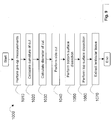
- FIG. 9 illustrates a process 1000 of the laser system 10 according to an embodiment.
- the laser system 10 may start a surgical procedure performing pre-operation measurements (Action Block 1010). For example, in an ophthalmologic surgery for myopic correction, the myopic diopter is determined, the SLOW_Z position is determined, and so on.
- the laser system 10 calculates the radius of curvature based on the amount of correction, e.g ., the myopic correction determined in pre-operation measurements (Action Block 1020), as shown, for example, in equations (2) and (3) above.
- the laser system 10 calculates the diameter of the incision (Action Block 1030), as shown by D CUT in FIG . 8 .
- D CUT is equal to or greater than the diameter of the to-be-extracted lenticule (DL in FIG . 8 ).
- the laser system 10 first performs side incision to provide a vent for gas that can be produced in the lenticular surface dissections, and for tissue extraction later on (Action Block 1040).
- the laser system 10 then performs the bottom lenticular surface dissection (Action Block 1050) before performing the top lenticular surface dissection (Action Block 1060).
- the lenticular tissue is then extracted (Action Block 1070).
- the laser system 10 may also be used to produce other three-dimensional surface shapes, including toric surfaces for correcting hyperopia and astigmatism.
- the laser system 10 may also be used for laser material processing and micromachining for other transparent materials. Correction of hyperopia by the laser system 10 is discussed in detail below.
- FIG . 11 illustrates why utilizing these patterns using SmILE is impractical and unfeasible.
- the cross-sectional view of the cornea 160 in FIG . 11 includes a sidecut 120, an upper surface cut 130, lower surface cut 140 and a ring-shaped cut 170 generated by a SmILE procedure.
- the cornea 160 maintains an uncut annular center portion 180 that remains attached to an anterior portion and posterior portion of the cornea 160.
- This cut pattern is geometrically problematic as the clean removal of the ring cut 170 through the side cut 120 as a single ring is impeded by the center portion 180.
- a flap provided in a LASIK procedure allows a ring shape to be easily extracted
- the use of a sidecut without a flap prevents the ring-shaped stroma material from being extracted from the tunnel like incision without breaking apart.
- a ring-shaped lenticule is not suitable for correcting hyperopia using the SmILE procedure since the ring cut 170 will break up unpredictably during removal through the side cut 120.
- Some LASIK procedures correct hyperopia by removing cornea stroma material to increase the steepness of the cornea. For example, outward portions of the cornea are cut and removed while a center portion remains untouched except for the flap. Once the flap is folded back over, the flap fills the void vacated by the removed cornea stroma material and merges with the cornea. The cornea thus becomes steeper and a desired vision correction is achieved.
- the curve of the flap does not match the curve of the cornea such that the merger of the flap and cornea creates folds in the stroma that increase light scattering and create undesirable aberrations.
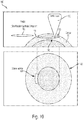
- FIG . 12 illustrates an exemplary lenticular incision 1200 that steepens the cornea by cutting and removing a symmetric concave lens-shaped stroma material from a cornea 1240. From an optical focus power perspective, the concave shape of the lenticule 1220 is equivalent to steepening the cornea or adding a convex lens in front of the eye.
- the incision includes a peripheral portion 1230 or tapering portion providing ideal merging of the cornea after the lenticule 1220 is extracted without folding in a top surface or bottom surface.
- FIG. 13 illustrates an exemplary lenticular incision 1300 using a surgical ophthalmic laser system according to an embodiment of the present invention.
- SmILE techniques may be applied in conjunction with FIG . 13 to treat hyperopia using a sub-nanosecond laser.
- a cross-sectional view 1302 and top view 1304 are provided of the lenticule cuts 1310, 1320 and side cut 1350.
- a patient interface 1340 is pressed against a cornea 1306.
- the lenticular incision includes a bottom lens surface 1310 and a top lens surface 1320.
- the bottom surface 1310 includes a radius of curvature R1 and the top surface 1320 includes a radius of curvature R2.
- a side cut 1350 is performed first to provide a path for gas to vent to prevent the formation of bubbles.
- a bottom surface cut 1310 is then performed prior to performing a top surface cut 1320 to prevent the cutting beam from being blocked by bubbles generated by previous cornea dissection.
- the top and bottom surface cuts each include a central portion and a peripheral portion. The central portions are concave while the peripheral portions of the top and bottom cuts tapers (diminishes) towards each other to meet. The tapering peripheral portions minimize light scattering at the edges and further optimizes the matching of the cut surfaces and prevent folding after the lenticule has been removed.
- the thickest portion of the cut is provided at the boundary of the taper portion and the concave portion.
- the bottom and top surfaces are preferably mirror symmetric about a plane 1360.
- exemplary lenticular incisions allow lenticular tissue to be extracted in a single unbroken piece through the sidecut.
- the taper of the peripheral portions allows smooth extraction through the sidecut as a gradual slope is provided.
- the peripheral portions also support the merging of the top and bottom portions of the cornea as a top surface and bottom surface compress back together to form a smooth merge. Without a taper to the peripheral portions, the apex of the central portions would never merge and would form a permanent gap.
- a concave lens cut includes a top concave lenticular incision and a bottom concave lenticular incision of a lens in the subject's eye.
- the concave lens cut may include at least one of a spherical surface., a cylindrical component, and any high order component.
- the top concave lenticular incision and the bottom concave lenticular incision may be mirror symmetric or nearly mirror symmetric to each other so long as the merging of the top surface and bottom surface does not create folding.
- the system may operate with a laser having a wavelength in a range between 350 nanometer and 1100 nanometer and a pulse width in a range between 10 femtosecond and 1 nanosecond.
- a top layer cut is longer than a bottom layer cut.
- the top and bottom cornea portions do not ideally merge as the top surface must fold in and compress in order to merge with shorter layer cut. With this fold created by the dissection, light scattering is increased.
- a mirror symmetric cut along a center line allows ideal merge with no folding between a top layer and bottom layer. Consequently, there is less light scattering.
- a lens edge thickness is given by ⁇ E , ⁇ E1 , ⁇ E2 .
- a lens depth H is given as a distance between an anterior of the cornea 1306 and the plane 1360.
- the bottom surface 1310 and top surface 1320 have a lens diameter D L , a lens center thickness ⁇ c and a shape defined by respective curves Z 1,L (x,y) and Z 2,L (x,y).
- the central thickness ⁇ c should be minimized.
- Each of the bottom lens surface cut 1310 and the top lens surface cut 1320 includes a tapering zone 1330 along a periphery of the cuts.
- the tapering zone 1330 is defined by a tapering zone width ⁇ and the curves Z 1,T (x,y) and Z 2,T (x,y).
- a sidecut 1350 is provided from a surface of the cornea to the tapering zone 1330 for removal of the lenticule.
- the sidecut may meet the tapering zone 1330 on the mirror plane 1360 or other suitable extraction point.
- the shape and dimensions of the cuts may include additional correction for higher order aberrations and may be computed from measured vision errors. In some embodiments, approximately 50% of the total hyperopic correction is applied to each of the two mutually mirror-imaged cut surfaces.
- the thickest portion of the concave lens cut is provided at the intersection of the tapering zone and the concave lens cuts which correspond to a portion of the cornea that is thicker than a center portion of the cornea. Consequently, from the standpoint of cornea thickness, correcting hyperopia is more tolerable than correcting myopia, where the thicker portion of the lens to be removed is at the center of the cornea, corresponding to a thinner portion of the cornea.
- the shape of the tapering zone 1330 need not be linear in shape.
- the tapering zone may be curved or any shape that minimizes light scattering at the cutting junctions and optimizes the matching of the two cut surfaces after lens extraction.
- the peripheral zone may be linear or a higher order polynomial.
- Some embodiments of the invention apply to single-spot scanning methods applied in femtosecond laser systems.
- the invention also applies to cornea incisions using UV 355 nm sub-nanosecond lasers.
- Equations (2), (8) and (9) are used to estimate the thickness of the concave lens.
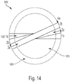
- FIG. 14 illustrates an exemplary scanning process 1400 using a surgical ophthalmic laser system according to an embodiment of the present invention.
- FIG . 14 illustrates another embodiment of the "Fast-Scan-Slow-Sweep" scanning described previously. While performing an XY scan, Z values can be calculated from Eqs.(1)-(9), and the desired three-dimensional concave lens-shape cutting surfaces may be generated.
- a top view of the lenticular incision illustrates three exemplary sweeps 1430 (1A to 1B), (2A to 2B) and (3A to 3B), with each sweep going through (i.e., going over) the concave lenticular incision 1410 and tapering zone 1420.
- the lenticular incision is performed in the following steps:
- FIG. 15 is a flowchart illustrating an exemplary surgery process 1500 according to an embodiment of the present invention.
- the laser system 10 may start a surgical procedure performing pre-operation measurements (Action Block 1510). For example, in an ophthalmologic surgery for hyperopic correction, the hyperopic diopter is determined, the SLOW_Z position is determined, and so on.
- the laser system 10 calculates the shape of the incisions (Action Block 1520).
- the laser system 10 calculates the radius of curvatures based on the amount of correction, e . g ., the hyperopic correction determined in pre-operation measurements (Action Block 1530), as determined by Equations ( 4 )-( 8 ), for example.
- the laser system 10 first performs a side incision to provide a vent for gas that can be produced in the lenticular surface dissections, and for tissue extraction later on (Action Block 1540).
- the laser system 10 then performs the bottom lenticular surface dissection (Action Block 1550) before performing the top lenticular surface dissection (Action Block 1560). Performing the dissections in this order allows gas to vent out of the cornea instead of becoming trapped in gas bubbles within the cornea.
- the lenticular tissue is then extracted (Action Block 1570).
Description
- The disclosure relates generally to laser-assisted ophthalmic procedures, and more particularly, the invention relates to systems for lenticular incisions in the cornea.
- Vision impairments such as myopia (near-sightedness), hyperopia and astigmatism can be corrected using eyeglasses or contact lenses. Alternatively, the cornea of the eye can be reshaped surgically to provide the needed optical correction. Eye surgery has become commonplace with some patients pursuing it as an elective procedure to avoid using contact lenses or glasses to correct refractive problems, and others pursuing it to correct adverse conditions such as cataracts. And, with recent developments in laser technology, laser surgery is becoming the technique of choice for ophthalmic procedures. The reason eye surgeons prefer a surgical laser beam over manual tools like microkeratomes and forceps is that the laser beam can be focused precisely on extremely small amounts of ocular tissue, thereby enhancing accuracy and reliability of the procedure. These in turn enable better wound healing and recovery following surgery.
- Hyperopia (far-sightedness) is a visual impairment where light entering the eye does not focus at the retina to produce a sharp image as desired, but rather focuses at a location behind the retina such that a patient sees a blurred disc. The basic principle to treating hyperopia is to add positive focusing power to the cornea. For instance, a hyperopic eye can be treated by placing a convex lens in front of the eye to add a positive focusing power to the eye. After correction, light passing through the convex lens and into the eye focuses at the retina to form a sharp image.
- Different laser eye surgical systems use different types of laser beams for the various procedures and indications. These include, for instance, ultraviolet lasers, infrared lasers, and near-infrared, ultra-short pulsed lasers. Ultra-short pulsed lasers emit radiation with pulse durations as short as 10 femtoseconds and as long as 3 nanoseconds, and a wavelength between 300 nm and 3000 nm. Examples of laser systems that provide ultra-short pulsed laser beams include the Abbott Medical Optics iFS Advanced Femtosecond Laser, the IntraLase FS Laser, and OptiMedica's Catalys Precision Laser System.
- Prior surgical approaches for reshaping the cornea include laser assisted in situ keratomileusis (hereinafter "LASIK"), photorefractive keratectomy (hereinafter "PRK") and Small Incision Lens Extraction (hereinafter "SmILE").
- In the LASIK procedure, an ultra-short pulsed laser is used to cut a corneal flap to expose the corneal stroma for photoablation with ultraviolet beams from an excimer laser. Photoablation of the corneal stroma reshapes the cornea and corrects the refractive condition such as myopia, hyperopia, astigmatism, and the like.
- It is known that if part of the cornea is removed, the pressure exerted on the cornea by the aqueous humor in the anterior chamber of the eye will act to close the void created in the cornea, resulting in a reshaped cornea. By properly selecting the size, shape and location of a corneal void, one can obtain the desired shape, and hence, the desired optical properties of the cornea.
- In current laser surgery treatments that correct hyperopia using LASIK and PRK, positive focusing power is added to the cornea by steepening the curvature of the cornea, by for example, removing a ring-shaped stroma material from the cornea. In a LASIK procedure, a flap is first created, then lifted up for the ring-shaped stroma material to be removed or ablated away by an excimer laser. The center of the cornea is not removed while more outward portions of the cornea are removed. The flap is then put back into place. The cornea thus steepens due to the void created in the cornea. Common patterns that steepen the cornea include ring, tunnel and toric shapes. LASIK can typically correct hyperopia for up to 5D (diopter). In a PRK procedure where no flap is created, the epithelium layer is first removed, and the ring-shaped stroma material is then removed by an excimer laser. The epithelium layer will grow back within a few days after the procedure.
- Recently, surgeons have started using another surgical technique other than LASIK and PRK for refractive correction. Instead of ablating corneal tissue with an excimer laser following the creation of a corneal flap, the newer SmILE technique involves tissue removal with two femtosecond laser incisions that intersect to create a lenticule for extraction. Lenticular extractions can be performed either with or without the creation of a corneal flap. With the flapless procedure, a refractive lenticule is created in the intact portion of the anterior cornea and removed through a small incision.
- In the SmILE procedure illustrated in
FIG. 10 , afemtolaser 110 is used to make aside cut 120, an upper surface cut 130 and a lower surface cut 140 that forms acut lens 150. A tweezer, for example, is then used to extract the cut lens beneath the anterior surface of thecornea 160 through the side cut 120. Recently, SmILE has been applied to treat myopia by cutting and extracting a convex lens-shaped stroma material with a femtosecond laser. However, SmILE techniques have not been applied in treating hyperopia. - Furthermore, as shown in
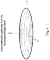
FIG. 1 , conventional femtosecond laser surgery systems generate a curved dissection surface to make a lenticular incision by scanning a laser focus on the intended dissection surface through a XY-scanning device and a Z-scanning device. This method does not use the more advantageous "fast-scan-slow-sweep" scanning scheme with femtosecond lasers having high repetition rate ("rep rate"), for e.g., in the MHz range. Using the "fast-scan-slow-sweep" scanning scheme for a lenticular incision, however, will generate vertical "steps" and will require many vertical side cuts, resulting in a lenticular dissection surface that is not smooth. - Therefore, there is a need for improved systems to generate corneal lenticular incisions for high repetition rate femtosecond lasers to correct hyperopia. A prior art femtosecond laser device for generating corneal lenticular incisions is known from
DE102006053119A1 . - The invention is defined by
claim 1. Preferred embodiments are defined by the dependent claims. Further embodiments disclosed herein are for exemplary purpose only and do not form part of the invention. - To obviate one or more problems due to limitations and disadvantages of the related art, this disclosure provides embodiments including an ophthalmic surgical laser system comprising a laser delivery system for delivering a pulsed laser beam to a target in a subject's eye, an XY-scan device to deflect the pulsed laser beam, a Z-scan device to modify a depth of a focus of the pulsed laser beam, and a controller configured to form a top lenticular incision and a bottom lenticular incision of a lens on the subject's eye. The XY-scan device deflects the pulsed laser beam to form a scan line. The scan line is tangential to the parallels of latitude of the lens. The scan line is then moved along the meridians of longitude of the lens. The top lenticular incision is moved over the top surface of the lens through the apex of the top surface of the lens, and the bottom lenticular incision is moved over the bottom surface of the lens through the apex of bottom surface of the lens.
- Other embodiments disclose an ophthalmic surgical laser system comprising a laser delivery system for delivering a pulsed laser beam to a target in a subject's eye, an XY-scan device to deflect the pulsed laser beam, a Z-scan device to modify a depth of a focus of the pulsed laser beam, and a controller configured to form a top concave lenticular incision and a bottom concave lenticular incision of a lens on the subject's eye.
- This summary and the following detailed description are merely exemplary, illustrative, and explanatory, and are not intended to limit, but to provide further explanation of the invention as claimed. Additional features and advantages of the invention will be set forth in the descriptions that follow, and in part will be apparent from the description, or may be learned by practice of the invention. The objectives and other advantages of the invention will be realized and attained by the structure particularly pointed out in the written description, claims and the appended drawings.
- The novel features of the invention are set forth with particularity in the appended claims. A better understanding of the features and advantages will be facilitated by referring to the following detailed description that sets forth illustrative embodiments using principles of the invention, as well as to the accompanying drawings, in which like numerals refer to like parts throughout the different views. Like parts, however, do not always have like reference numerals. Further, the drawings are not drawn to scale, and emphasis has instead been placed on illustrating the principles of the invention. All illustrations are intended to convey concepts, where relative sizes, shapes, and other detailed attributes may be illustrated schematically rather than depicted literally or precisely.
-
FIG. 1 illustrates a conventional lenticular cut via scanning a single focus spot. -
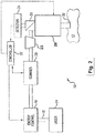
FIG. 2 is a simplified diagram of a surgical ophthalmic laser system according to an embodiment of the present invention. -
FIG. 3 is another simplified diagram of a surgical ophthalmic laser system according to an embodiment of the present invention. -
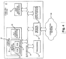
FIG. 4 is a simplified diagram of a controller of a surgical ophthalmic laser system according to an embodiment of the present invention. -
FIG. 5 illustrates an exemplary scanning of a surgical ophthalmic laser system according to an embodiment of the present invention. -
FIG. 6 illustrates an exemplary lenticular incision using a fast-scan-slow-sweep scheme of a surgical ophthalmic laser system according to an embodiment of the present invention. -
FIG. 7 illustrates a geometric relation between a fast scan line and an intended spherical dissection surface of a surgical ophthalmic laser system according to an embodiment of the present invention. -
FIG. 8 illustrates an exemplary lenticular incision using a surgical ophthalmic laser system according to an embodiment of the present invention. -
FIG. 9 is a flowchart illustrating a process according to an embodiment of the present invention. -
FIG. 10 illustrates a conventional Small Incision Lenticule Extraction procedure. -
FIG. 11 illustrates a hypothetical Small Incision Lenticule Extraction procedure. -
FIG. 12 illustrates an exemplary lenticular incision process according to an embodiment of the present invention. -
FIG. 13 illustrates an exemplary lenticular incision using a surgical ophthalmic laser system according to an embodiment of the present invention. -
FIG. 14 illustrates an exemplary scanning process using a surgical ophthalmic laser system according to an embodiment of the present invention. -
FIG. 15 is a flowchart illustrating an exemplary surgery process according to an embodiment of the present invention. - Referring to the drawings,
FIG. 2 shows asystem 10 for making an incision in amaterial 12. Thesystem 10 includes, but is not limited to, a laser 14 capable of generating apulsed laser beam 18, anenergy control module 16 for varying the pulse energy of thepulsed laser beam 18, a Z-scanner 20 for modifying the depth of thepulse laser beam 18, acontroller 22, a prism 23 (e.g., a Dove or Pechan prism, or the like), and an XY-scanner 28 for deflecting or directing thepulsed laser beam 18 from the laser 14 on or within thematerial 12. Thecontroller 22, such as a processor operating suitable control software, is operatively coupled with the Z-scanner 20, the XY-scanner 28, and theenergy control unit 16 to direct ascan line 30 of the pulsed laser beam along a scan pattern on or in thematerial 12. In this embodiment, thesystem 10 further includes abeam splitter 26 and a detector 24 coupled to thecontroller 22 for a feedback control mechanism (not shown) of thepulsed laser beam 18. Other feedback methods may also be used, including but not necessarily limited to position encoder on thescanner 20, or the like. In an embodiment, the pattern of pulses may be summarized in machine readable data of tangible storage media in the form of a treatment table. The treatment table may be adjusted according to feedback input into thecontroller 22 from an automated image analysis system in response to feedback data provided from an ablation monitoring system feedback system (not shown). Optionally, the feedback may be manually entered into thecontroller 22 by a system operator. The feedback may also be provided by integrating a wavefront measurement system (not shown) with thelaser surgery system 10. Thecontroller 22 may continue and/or terminate a sculpting or incision in response to the feedback, and may also modify the planned sculpting or incision based at least in part on the feedback. Measurement and imaging systems are further described inU.S. Patent Nos. 6,315,413 and8,260,024 . - In an embodiment, the
system 10 uses a pair of scanning mirrors or other optics (not shown) to angularly deflect and scan thepulsed laser beam 18. For example, scanning mirrors driven by galvanometers may be employed where each of the mirrors scans thepulsed laser beam 18 along one of two orthogonal axes. A focusing objective (not shown), whether one lens or several lenses, images thepulsed laser beam 18 onto a focal plane of thesystem 10. The focal point of thepulsed laser beam 18 may thus be scanned in two dimensions (e.g., the x-axis and the y-axis) within the focal plane of thesystem 10. Scanning along the third dimension, i.e., moving the focal plane along an optical axis (e.g., the z-axis), may be achieved by moving the focusing objective, or one or more lenses within the focusing objective, along the optical axis. - Laser 14 may comprise a femtosecond laser capable of providing pulsed laser beams, which may be used in optical procedures, such as localized photodisruption (e.g., laser induced optical breakdown). Localized photodisruptions can be placed at or below the surface of the material to produce high-precision material processing. For example, a micro-optics scanning system may be used to scan the pulsed laser beam to produce an incision in the material, create a flap of the material, create a pocket within the material, form removable structures of the material, and the like. The term "scan" or "scanning" refers to the movement of the focal point of the pulsed laser beam along a desired path or in a desired pattern.
- In other embodiments, the laser 14 may comprise a laser source configured to deliver an ultraviolet laser beam comprising a plurality of ultraviolet laser pulses capable of photodecomposing one or more intraocular targets within the eye.
- Although the
laser system 10 may be used to photoalter a variety of materials (e.g., organic, inorganic, or a combination thereof), thelaser system 10 is suitable for ophthalmic applications in some embodiments. In these cases, the focusing optics direct thepulsed laser beam 18 toward an eye (for example, onto or into a cornea) for plasma mediated (for example, non-UV) photoablation of superficial tissue, or into the stroma of the cornea for intrastromal photodisruption of tissue. In these embodiments, thesurgical laser system 10 may also include a lens to change the shape (for example, flatten or curve) of the cornea prior to scanning thepulsed laser beam 18 toward the eye. - The
laser system 10 is capable of generating thepulsed laser beam 18 with physical characteristics similar to those of the laser beams generated by a laser system disclosed inU.S. Pat. No. 4,764,930 ,U.S. Pat. No. 5,993,438 , andU.S. Patent Application Serial No. 12/987,069, filed January 7, 2011 -
FIG. 3 shows another exemplary diagram of thelaser system 10.FIG. 3 shows a moveable XY-scanner (or XY-stage) 28 of a miniaturized femtosecond laser system. In this embodiment, thesystem 10 uses a femtosecond oscillator, or a fiber oscillator-based low energy laser. This allows the laser to be made much smaller. The laser-tissue interaction is in the low-density-plasma mode. An exemplary set of laser parameters for such lasers include pulse energy in the 50-100nJ range and pulse repetitive rates (or "rep rates") in the 5-20MHz range. A fast-Z scanner 20 and aresonant scanner 21 direct thelaser beam 18 to theprism 23. When used in an ophthalmic procedure, thesystem 10 also includes apatient interface 31 design that has a fixed cone nose and a portion that engages with the patient's eye. A beam splitter is placed inside the cone of the patient interface to allow the whole eye to be imaged via visualization optics. In one embodiment, thesystem 10 uses: optics with a 0.6 numerical aperture (NA) which would produce 1.1 µm Full Width at Half Maximum (FWHM) focus spot size; and aresonant scanner 21 that produces 1-2 mm scan line with the XY-scanner scanning the resonant scan line to a 10mm field. Theprism 23 rotates the resonant scan line in any direction on the XY plane. The fast-Z scanner 20 sets the incision depth and produces a side cut. Thesystem 10 may also include an auto-Z module 32 to provide depth reference. The miniaturizedfemtosecond laser system 10 may be a desktop system so that the patient sits upright while being under treatment. This eliminates the need of certain opto-mechanical arm mechanism(s), and greatly reduces the complexity, size, and weight of the laser system. Alternatively, the miniaturized laser system may be designed as a conventional femtosecond laser system, where the patient is treated while lying down. -
FIG. 4 illustrates a simplified block diagram of anexemplary controller 22 that may be used by thelaser system 10 according to an embodiment of this invention.Controller 22 typically includes at least oneprocessor 52 which may communicate with a number of peripheral devices via abus subsystem 54. These peripheral devices may include astorage subsystem 56, comprising amemory subsystem 58 and afile storage subsystem 60, userinterface input devices 62, user interface output devices 64, and anetwork interface subsystem 66.Network interface subsystem 66 provides an interface tooutside networks 68 and/or other devices.Network interface subsystem 66 includes one or more interfaces known in the arts, such as LAN, WLAN, Bluetooth, other wire and wireless interfaces, and so on. - User
interface input devices 62 may include a keyboard, pointing devices such as a mouse, trackball, touch pad, or graphics tablet, a scanner, foot pedals, a joystick, a touch screen incorporated into a display, audio input devices such as voice recognition systems, microphones, and other types of input devices. In general, the term "input device" is intended to include a variety of conventional and proprietary devices and ways to input information intocontroller 22. - User interface output devices 64 may include a display subsystem, a printer, a fax machine, or non-visual displays such as audio output devices. The display subsystem may be a flat-panel device such as a liquid crystal display (LCD), a light emitting diode (LED) display, a touchscreen display, or the like. The display subsystem may also provide a non-visual display such as via audio output devices. In general, the term "output device" is intended to include a variety of conventional and proprietary devices and ways to output information from
controller 22 to a user. -
Storage subsystem 56 can store the basic programming and data constructs that provide the functionality of the various embodiments of the present invention. For example, a database and modules implementing the functionality of the methods of the present invention, as described herein, may be stored instorage subsystem 56. These software modules are generally executed byprocessor 52. In a distributed environment, the software modules may be stored on a plurality of computer systems and executed by processors of the plurality of computer systems.Storage subsystem 56 typically comprisesmemory subsystem 58 andfile storage subsystem 60. -
Memory subsystem 58 typically includes a number of memories including a main random access memory (RAM) 70 for storage of instructions and data during program execution and a read only memory (ROM) 72 in which fixed instructions are stored.File storage subsystem 60 provides persistent (non-volatile) storage for program and data files.File storage subsystem 60 may include a hard disk drive along with associated removable media, a Compact Disk (CD) drive, an optical drive, DVD, solid-state memory, and/or other removable media. One or more of the drives may be located at remote locations on other connected computers at other sites coupled tocontroller 22. The modules implementing the functionality of the present invention may be stored byfile storage subsystem 60. -
Bus subsystem 54 provides a mechanism for letting the various components and subsystems ofcontroller 22 communicate with each other as intended. The various subsystems and components ofcontroller 22 need not be at the same physical location but may be distributed at various locations within a distributed network. Althoughbus subsystem 54 is shown schematically as a single bus, alternate embodiments of the bus subsystem may utilize multiple busses. - Due to the ever-changing nature of computers and networks, the description of
controller 22 depicted inFIG. 4 is intended only as an example for purposes of illustrating only one embodiment of the present invention. Many other configurations ofcontroller 22, having more or fewer components than those depicted inFIG. 4 , are possible. - As should be understood by those of skill in the art, additional components and subsystems may be included with
laser system 10. For example, spatial and/or temporal integrators may be included to control the distribution of energy within the laser beam, as described inU.S. Patent No. 5,646,791 , which is incorporated herein by reference. Ablation effluent evacuators/filters, aspirators, and other ancillary components of the surgical laser system are known in the art, and may be included in the system. In addition, an imaging device or system may be used to guide the laser beam. Further details of suitable components of subsystems that can be incorporated into an ophthalmic laser system for performing the procedures described here can be found in commonly-assignedU.S. Patent No. 4,665,913 ,U.S. Patent No. 4,669,466 ,U.S. Patent No. 4,732,148 ,U.S. Patent No. 4,770,172 ,U.S. Patent No. 4,773,414 ,U.S. Patent No. 5,207,668 ,U.S. Patent No. 5,108,388 ,U.S. Patent No. 5,219,343 ,U.S. Patent No. 5,646,791 ,U. S. Patent No. 5,163,934 ,U.S. Patent No. 8,394,084 ,U.S. Patent No. 8,403,921 ,U.S. Patent No. 8,690,862 ,U.S. Patent No. 8,709,001 ,U.S. Application Serial No. 12/987,069, filed January 7, 2011 U.S. Application Serial No. 13/798,457 filed March 13, 2013 - In an embodiment, the
laser surgery system 10 includes a femtosecond oscillator-based laser operating in the MHz range, for example, 10 MHz, for example, from several MHz to tens of MHz. For ophthalmic applications, the XY-scanner 28 may utilize a pair of scanning mirrors or other optics (not shown) to angularly deflect and scan thepulsed laser beam 18. For example, scanning mirrors driven by galvanometers may be employed, each scanning thepulsed laser beam 18 along one of two orthogonal axes. A focusing objective (not shown), whether one lens or several lenses, images the pulsed laser beam onto a focal plane of thelaser surgery system 10. The focal point of thepulsed laser beam 18 may thus be scanned in two dimensions (e.g., the X-axis and the Y-axis) within the focal plane of thelaser surgery system 10. Scanning along a third dimension, i.e., moving the focal plane along an optical axis (e.g., the Z-axis), may be achieved by moving the focusing objective, or one or more lenses within the focusing objective, along the optical axis. It is noted that in many embodiments, the XY-scanner 28 deflects thepulse laser beam 18 to form a scan line. - In other embodiments, the beam scanning can be realized with a "fast-scan-slow-sweep" scanning scheme. The scheme consists of two scanning mechanisms: first, a high frequency fast scanner is used to produce a short, fast scan line (e.g., a
resonant scanner 21 ofFIG. 3 ); second, the fast scan line is slowly swept by much slower X, Y, and Z scan mechanisms.FIG. 5 illustrates a scanning example of alaser system 10 using an 8 kHzresonant scanner 21 to produce a scan line of about 1 mm and a scan speed of about 25m/sec, and X, Y, and Z scan mechanisms with the scan speed smaller than 0.1m/sec. The fast scan line may be perpendicular to the optical beam propagation direction, i.e., it is always parallel to the XY plane. The trajectory of the slow sweep can be any three dimensional curve drawn by the X, Y, and Z scanning devices (e.g., XY-scanner 28 and Z-scanner 20). An advantage of the "fast-scan-slow-sweep" scanning scheme is that it only uses small field optics (e.g., a field diameter of 1.5 mm) which can achieve high focus quality at relatively low cost. The large surgical field (e.g., a field diameter of 10 mm or greater) is achieved with the XY-scanner, which may be unlimited. - In another embodiment shown in
FIG. 6 , thelaser system 10 creates a smooth lenticular cut using the "fast-scan-slow-sweep" scanning scheme under a preferred procedure. First, in a three dimensional lenticular cut, the fast scan line is preferably placed tangential to the parallels oflatitude 610. For example, in the miniaturized flapmaker laser system 10 ofFIG. 3 , this can be realized by adjusting aprism 23 to the corresponding orientations via software, e.g., via thecontroller 22. Second, the slow sweep trajectory preferably moves along the meridians oflongitude 620. For example, in the miniaturized flap maker system ofFIG. 3 , this can be done by coordinating theXY scanner 28, and the Fast-Z scanner 20 via the software, e.g., via thecontroller 22. The procedure starts with the scan line being parallel to the XY plane, and sweeps through the apex of the lens, following the curvature with the largest diameter (see alsoFIG. 8 ). With this preferred procedure, there are no vertical "steps" in the dissection, and vertical side cuts are eliminated. As will be analyzed herein below, the deviations between the laser focus locations and the intended spherical surface dissections are also minimized. -
FIG. 7 shows the geometric relation between thefast scan line 710 and the intendedspherical dissection surface 720, e.g., of a lens, especially the distance deviation (δ) between the end point B of thescan line 720 and point A on the intendeddissection surface 720. The maximum deviation δ is the distance between point A and point B, and is given by
surface dissection 720, and L is the length of the fast scan. - In an exemplary case of myopic correction, the radius of curvature of the surface dissection may be determined by the amount of correction, ΔD, using the following equation


- In an embodiment,
FIG. 8 shows an exemplarylenticular incision 900 for extraction using thelaser system 10.FIG. 8 shows an exemplarycross-sectional view 910 illustrating a patient interface 905 (orpatient interface 31 as shown inFIG. 3 ), cornea 906, andlenticular incision volume 915, which will be referred herein as lens to be extracted. Rt and Rb are the radii of curvature for the top surface and bottom surface of a lenticular incision, respectively. ZFt (Zt) is the depth of the top surface of the lenticular incision. ZFb (Zb) is the depth of the bottom surface of the lenticular incision. The Z depths may be calculated based on the respective radii. LT is the lens thickness at the lens apex, or center thickness of the lens. ZA is depth of the lens apex. DL is the diameter of the lenticular incision, or the lens. {Z_SLOW = 0} is the Z reference position before thelaser system 10 calculates and sets Z_SLOW, e.g., {Z_SLOW = ZA + LT/2} the center depth of the lens, which remains fixed for the duration of the incision procedure. Z_SLOW may then be the reference position for the Z-scanner for top and bottom incision surfaces. In an embodiment, the diameter of the lens may be received from an operator of thelaser system 10, or may be calculated by thelaser system 10. The thickness of the lens may be determined, for example, by the total amount of correction (e.g., diopter) and the diameter of the lens. - A
top view 950 of thelenticular incision 900 illustrates three exemplary sweeps (1A to 1B), (2A to 2B) and (3A to 3B), with each sweep going through (i.e., going over) thelenticular incision apex 955. The incision, or cut, diameter 957 (DCUT) should be equal to or greater than the to-be-extracted lenticular incision diameter 917 (DL). Atop view 980 shows the top view of one exemplary sweep. In an embodiment, the lenticular incision is performed in the following steps: - 1. Calculate the radius of curvature based on the amount of correction, e.g., a myopic correction.
- 2. Select the diameter for the lenticular incision to be extracted.
- 3. Perform the side incision first (not shown) to provide a vent for gas that can be produced in the lenticular surface dissections. This is also the incision for the entry of forceps and for lens extraction.
- 4. Perform bottom surface dissection (the lower dissection as shown in cross-sectional view 910). In doing so, the fast scan line is preferably kept tangential to the parallels of latitude, and the trajectory of the slow sweep drawn by X, Y, and Z scanning devices moves along the meridians of longitude (near south pole in a sequence of 1A → 1B (first sweep of lenticular cut),
2A → 2B (second sweep of lenticular cut),3A → 3B (third sweep of lenticular cut), and so on, until the full bottom dissection surface is generated. - 5. Perform the top surface dissection (the upper dissection as shown in the cross-sectional view 910) in a similar manner as the bottom dissection is done. It is noted that the bottom dissection is done first. Otherwise, the bubble generated during the top dissection will block the laser beam in making the bottom dissection.
- For illustrative purposes, in a myopic correction of ΔD = 10 diopter (i.e., 1/m), using equation (3), R = 75.2mm, which is indeed much greater than the length L of the fast scan. Assuming a reasonable scan line length of L = 1mm, using equation (1), the deviation δ ≈ 1.7 µm. This deviation is thus very small. For comparison purpose, the depth of focus of a one micron (FWHM) spot size at 1µm wavelength is about ±3 µm, meaning the length of focus is greater than the deviation δ.
-
FIG. 9 illustrates aprocess 1000 of thelaser system 10 according to an embodiment. Thelaser system 10 may start a surgical procedure performing pre-operation measurements (Action Block 1010). For example, in an ophthalmologic surgery for myopic correction, the myopic diopter is determined, the SLOW_Z position is determined, and so on. Thelaser system 10 calculates the radius of curvature based on the amount of correction, e.g., the myopic correction determined in pre-operation measurements (Action Block 1020), as shown, for example, in equations (2) and (3) above. Thelaser system 10 calculates the diameter of the incision (Action Block 1030), as shown by DCUT inFIG. 8 . DCUT is equal to or greater than the diameter of the to-be-extracted lenticule (DL inFIG. 8 ). Thelaser system 10 first performs side incision to provide a vent for gas that can be produced in the lenticular surface dissections, and for tissue extraction later on (Action Block 1040). Thelaser system 10 then performs the bottom lenticular surface dissection (Action Block 1050) before performing the top lenticular surface dissection (Action Block 1060). The lenticular tissue is then extracted (Action Block 1070). - In other embodiments, the
laser system 10 may also be used to produce other three-dimensional surface shapes, including toric surfaces for correcting hyperopia and astigmatism. Thelaser system 10 may also be used for laser material processing and micromachining for other transparent materials. Correction of hyperopia by thelaser system 10 is discussed in detail below. - Conventional laser surgery methods to correct hyperopia utilize cut patterns including ring-shaped incision patterns that steepen the curvature of a cornea. However,
FIG. 11 illustrates why utilizing these patterns using SmILE is impractical and unfeasible. The cross-sectional view of thecornea 160 inFIG. 11 includes asidecut 120, an upper surface cut 130, lower surface cut 140 and a ring-shapedcut 170 generated by a SmILE procedure. However, thecornea 160 maintains an uncutannular center portion 180 that remains attached to an anterior portion and posterior portion of thecornea 160. - This cut pattern is geometrically problematic as the clean removal of the ring cut 170 through the side cut 120 as a single ring is impeded by the
center portion 180. Whereas a flap provided in a LASIK procedure allows a ring shape to be easily extracted, the use of a sidecut without a flap prevents the ring-shaped stroma material from being extracted from the tunnel like incision without breaking apart. Thus, a ring-shaped lenticule is not suitable for correcting hyperopia using the SmILE procedure since the ring cut 170 will break up unpredictably during removal through the side cut 120. - Some LASIK procedures correct hyperopia by removing cornea stroma material to increase the steepness of the cornea. For example, outward portions of the cornea are cut and removed while a center portion remains untouched except for the flap. Once the flap is folded back over, the flap fills the void vacated by the removed cornea stroma material and merges with the cornea. The cornea thus becomes steeper and a desired vision correction is achieved. However, the curve of the flap does not match the curve of the cornea such that the merger of the flap and cornea creates folds in the stroma that increase light scattering and create undesirable aberrations.
- The inventions described herein overcome these limitations.
FIG. 12 illustrates an exemplarylenticular incision 1200 that steepens the cornea by cutting and removing a symmetric concave lens-shaped stroma material from acornea 1240. From an optical focus power perspective, the concave shape of thelenticule 1220 is equivalent to steepening the cornea or adding a convex lens in front of the eye. - Furthermore, extraction of the
lenticule 1220 as a whole piece through asidecut incision 1210 is assured and improved over a ring-shape cut, or a tunnel-like cut, or a toric cut. The incision includes aperipheral portion 1230 or tapering portion providing ideal merging of the cornea after thelenticule 1220 is extracted without folding in a top surface or bottom surface. -
FIG. 13 illustrates an exemplarylenticular incision 1300 using a surgical ophthalmic laser system according to an embodiment of the present invention. For example, SmILE techniques may be applied in conjunction withFIG. 13 to treat hyperopia using a sub-nanosecond laser. Across-sectional view 1302 andtop view 1304 are provided of thelenticule cuts FIG. 13 , a patient interface 1340 is pressed against acornea 1306. The lenticular incision includes abottom lens surface 1310 and atop lens surface 1320. Thebottom surface 1310 includes a radius of curvature R1 and thetop surface 1320 includes a radius of curvature R2. - A
side cut 1350 is performed first to provide a path for gas to vent to prevent the formation of bubbles. Abottom surface cut 1310 is then performed prior to performing a top surface cut 1320 to prevent the cutting beam from being blocked by bubbles generated by previous cornea dissection. The top and bottom surface cuts each include a central portion and a peripheral portion. The central portions are concave while the peripheral portions of the top and bottom cuts tapers (diminishes) towards each other to meet. The tapering peripheral portions minimize light scattering at the edges and further optimizes the matching of the cut surfaces and prevent folding after the lenticule has been removed. - As shown in
FIG. 13 , the thickest portion of the cut is provided at the boundary of the taper portion and the concave portion. For the top and bottom surfaces to match after lens extraction, the bottom and top surfaces are preferably mirror symmetric about a plane 1360. - These exemplary lenticular incisions allow lenticular tissue to be extracted in a single unbroken piece through the sidecut. The taper of the peripheral portions allows smooth extraction through the sidecut as a gradual slope is provided. The peripheral portions also support the merging of the top and bottom portions of the cornea as a top surface and bottom surface compress back together to form a smooth merge. Without a taper to the peripheral portions, the apex of the central portions would never merge and would form a permanent gap.
- A concave lens cut includes a top concave lenticular incision and a bottom concave lenticular incision of a lens in the subject's eye. The concave lens cut may include at least one of a spherical surface., a cylindrical component, and any high order component. The top concave lenticular incision and the bottom concave lenticular incision may be mirror symmetric or nearly mirror symmetric to each other so long as the merging of the top surface and bottom surface does not create folding.
- The system may operate with a laser having a wavelength in a range between 350 nanometer and 1100 nanometer and a pulse width in a range between 10 femtosecond and 1 nanosecond.
- In prior art solutions, a top layer cut is longer than a bottom layer cut. Under this configuration, the top and bottom cornea portions do not ideally merge as the top surface must fold in and compress in order to merge with shorter layer cut. With this fold created by the dissection, light scattering is increased. In contrast, a mirror symmetric cut along a center line allows ideal merge with no folding between a top layer and bottom layer. Consequently, there is less light scattering.
- A lens edge thickness is given by δE, δE1, δE2. A lens depth H is given as a distance between an anterior of the
cornea 1306 and the plane 1360. Thebottom surface 1310 andtop surface 1320 have a lens diameter DL, a lens center thickness δc and a shape defined by respective curves Z1,L(x,y) and Z2,L(x,y). In order to minimize the amount of dissected cornea stroma material removed, the central thickness δc should be minimized. For example, the central thickness may be a few µm, which can be achieved by using a laser beam with a high numerical aperture (such as NA = 0.6). - Each of the bottom
lens surface cut 1310 and the toplens surface cut 1320 includes atapering zone 1330 along a periphery of the cuts. Thetapering zone 1330 is defined by a tapering zone width ξ and the curves Z1,T(x,y) and Z2,T(x,y). - A
sidecut 1350 is provided from a surface of the cornea to thetapering zone 1330 for removal of the lenticule. The sidecut may meet thetapering zone 1330 on the mirror plane 1360 or other suitable extraction point. - With these parameters as described and illustrated, a set of equations are provided below that determine the three-dimensional shape of the lenticular cuts, assuming that the desired correction is purely defocus:


- The shape and dimensions of the cuts may include additional correction for higher order aberrations and may be computed from measured vision errors. In some embodiments, approximately 50% of the total hyperopic correction is applied to each of the two mutually mirror-imaged cut surfaces.
- It is noted that the thickest portion of the concave lens cut is provided at the intersection of the tapering zone and the concave lens cuts which correspond to a portion of the cornea that is thicker than a center portion of the cornea. Consequently, from the standpoint of cornea thickness, correcting hyperopia is more tolerable than correcting myopia, where the thicker portion of the lens to be removed is at the center of the cornea, corresponding to a thinner portion of the cornea.
- The shape of the
tapering zone 1330 need not be linear in shape. The tapering zone may be curved or any shape that minimizes light scattering at the cutting junctions and optimizes the matching of the two cut surfaces after lens extraction. The peripheral zone may be linear or a higher order polynomial. - Some embodiments of the invention apply to single-spot scanning methods applied in femtosecond laser systems. The invention also applies to cornea incisions using UV 355 nm sub-nanosecond lasers.
- For illustrative purposes, Equations (2), (8) and (9) are used to estimate the thickness of the concave lens. In a hyperopic correction of ΔD = 5 diopter (which is high end values for LASIK hyperopia procedures) and assuming that a symmetric shape of the lenticule is selected, R1 = R2 = 150.4 mm. Assuming DL = 7.0 mm and δc = 10 µm, then δE = δE1 + δE2 ≈ δC + DL 2·ΔD/[8(n-1)] ≈ 92µm.
-
FIG. 14 illustrates anexemplary scanning process 1400 using a surgical ophthalmic laser system according to an embodiment of the present invention.FIG. 14 illustrates another embodiment of the "Fast-Scan-Slow-Sweep" scanning described previously. While performing an XY scan, Z values can be calculated from Eqs.(1)-(9), and the desired three-dimensional concave lens-shape cutting surfaces may be generated. - A top view of the lenticular incision illustrates three exemplary sweeps 1430 (1A to 1B), (2A to 2B) and (3A to 3B), with each sweep going through (i.e., going over) the concave
lenticular incision 1410 and taperingzone 1420. In an embodiment, the lenticular incision is performed in the following steps: - 1. Calculate the radius of curvature based on the amount of correction, e.g., a hyperopic correction.
- 2. Select the diameter for the lenticular incision to be extracted.
- 3. Calculate the shape of the lenticular incisions (concave surface and taper).
- 4. Perform the side incision first (not shown) to provide a vent for gas that can be produced in the lenticular surface dissections. This is also the incision for the entry of forceps and for lens extraction.
- 5. Perform bottom surface dissection (the
bottom dissection 1310 as shown in cross-sectional view). In doing so, the fast scan line is preferably kept tangential to the parallels of latitude, and the trajectory of the slow sweep drawn by X, Y, and Z scanning devices moves along the meridians of longitude (near south pole in a sequence of 1A → 1B (first sweep of lenticular cut),2A → 2B (second sweep of lenticular cut),3A → 3B (third sweep of lenticular cut), and so on (4A) , until the full bottom dissection surface is generated. - 6. Perform the
top surface dissection 1320 in a similar manner as the bottom dissection is done. It is noted that the bottom dissection is done first. Otherwise, the bubble generated during the top dissection will block the laser beam in making the bottom dissection. -
FIG. 15 is a flowchart illustrating anexemplary surgery process 1500 according to an embodiment of the present invention. Thelaser system 10 may start a surgical procedure performing pre-operation measurements (Action Block 1510). For example, in an ophthalmologic surgery for hyperopic correction, the hyperopic diopter is determined, the SLOW_Z position is determined, and so on. Thelaser system 10 calculates the shape of the incisions (Action Block 1520). Thelaser system 10 calculates the radius of curvatures based on the amount of correction, e.g., the hyperopic correction determined in pre-operation measurements (Action Block 1530), as determined by Equations (4)-(8), for example. Thelaser system 10 first performs a side incision to provide a vent for gas that can be produced in the lenticular surface dissections, and for tissue extraction later on (Action Block 1540). Thelaser system 10 then performs the bottom lenticular surface dissection (Action Block 1550) before performing the top lenticular surface dissection (Action Block 1560). Performing the dissections in this order allows gas to vent out of the cornea instead of becoming trapped in gas bubbles within the cornea. The lenticular tissue is then extracted (Action Block 1570). - The use of the terms "a" and "an" and "the" and similar referents in the context of describing the invention (especially in the context of the following claims) are to be construed to cover both the singular and the plural, unless otherwise indicated herein or clearly contradicted by context. The terms "comprising," "having," "including," and "containing" are to be construed as open-ended terms (i.e., meaning "including, but not limited to,") unless otherwise noted. The term "connected" is to be construed as partly or wholly contained within, attached to, or joined together, even if there is something intervening. Recitation of ranges of values herein are merely intended to serve as a shorthand method of referring individually to each separate value falling within the range, unless otherwise indicated herein, and each separate value is incorporated into the specification as if it were individually recited herein. All methods described herein can be performed in any suitable order unless otherwise indicated herein or otherwise clearly contradicted by context. The use of any and all examples, or exemplary language (e.g., "such as") provided herein, is intended merely to better illuminate embodiments of the invention and does not pose a limitation on the scope of the invention unless otherwise claimed. No language in the specification should be construed as indicating any non-claimed element as essential to the practice of the invention.
- While certain illustrated embodiments of this disclosure have been shown and described in an exemplary form with a certain degree of particularity, those skilled in the art will understand that the embodiments are provided by way of example only, and that various variations can be made without departing from the scope of the invention.
Claims (15)
- An ophthalmic surgical laser system (10) comprising:a laser delivery system for focusing a pulsed laser beam, and for delivering the pulsed laser beam (18) to a target in a subject's eye;an XY-scan device (28) to deflect the pulsed laser beam;a Z-scan device (20) to modify a depth of a focus of the pulsed laser beam; anda controller (22) configured to control the XY-scan device and the Z-scan device to form a top lenticular incision and a bottom lenticular incision of a lens to be extracted from a cornea in the subject's eye;characterized in that the controller is configured to control the XY-scan device to deflect the pulsed laser beam to form a scan line (30) on or in the subject's eye, the scan line being tangential to the parallels of latitude of the lens, and control the XY-scan device and the Z-scan device to move the scan line along the meridians of longitude of the lens.
- The ophthalmic surgical laser system (10) of claim 1 further comprising a resonant scanner (21).
- The ophthalmic surgical laser system (10) of claim 1, wherein the scan line (30) is moved over the top surface of the lens through the apex of the top surface of the lens, and the scan line is moved over the bottom surface of the lens through the apex of bottom surface of the lens.
- The ophthalmic surgical laser system (10) of claim 1, wherein there is a deviation between an end point of the scan line and a point on the spherical surface of the lens.
- The ophthalmic surgical laser system (10) of claim 4, wherein the deviation is determined by

- The ophthalmic surgical laser system (10) of claim 4, wherein a depth of a focus of the pulsed laser beam is calculated based on a radius of curvature of a surface of the lens.
- The ophthalmic surgical laser system (10) of claim 1, wherein
the controller (22) is configured to control the XY-scan device (28) and the Z-scan device (20) to form at least one of:i) a concave lens cut, wherein the top lenticular incision comprises a top concave lenticular incision, and wherein the bottom lenticular incision comprises a bottom concave lenticular incision;ii) a top lenticular incision and a bottom lenticular incision of a lens that are mirror symmetric to each other in the subject's eye. - The ophthalmic surgical laser system (10) of claim 7, wherein the concave lens cut comprises a spherical surface.
- The ophthalmic surgical laser system (10) of claim 8, wherein the concave lens cut comprises a cylindrical component.
- The ophthalmic surgical laser system (10) of claim 9, wherein the concave lens cut comprises any high order component.
- The ophthalmic surgical laser system (10) of claim 7, wherein the top concave lenticular incision and the bottom concave lenticular incision are at least one of: i) mirror symmetric to each other; and ii) configured such that each comprises a central portion and a peripheral portion.
- The ophthalmic surgical laser system (10) of claim 11, wherein the peripheral portion comprises a tapering portion.
- The ophthalmic surgical laser system (10) of claim 11, wherein the peripheral portion is linear or a higher order polynomial.
- The ophthalmic surgical laser system (10) of claim 7, wherein the controller (22) is configured to control the XY-scan device and the Z-scan device to form the concave lens cut in a sequence of a side cut followed by the bottom lenticular incision and then followed by the top lenticular incision.
- The ophthalmic surgical laser system (10) of claim 7, wherein the laser delivery system includes a laser operating with at least one of: i) a wavelength in a range between 350 nanometer and 1100 nanometer; and ii) a pulse width in a range between 10 femtosecond and 1 nanosecond.
Priority Applications (1)
| Application Number | Priority Date | Filing Date | Title |
|---|---|---|---|
| EP21196071.1A EP3954346B1 (en) | 2014-09-25 | 2015-09-25 | Systems for lenticular laser incision |
Applications Claiming Priority (3)
| Application Number | Priority Date | Filing Date | Title |
|---|---|---|---|
| US201462055437P | 2014-09-25 | 2014-09-25 | |
| US201562183653P | 2015-06-23 | 2015-06-23 | |
| PCT/US2015/052199 WO2016049442A1 (en) | 2014-09-25 | 2015-09-25 | Systems for lenticular laser incision |
Related Child Applications (1)
| Application Number | Title | Priority Date | Filing Date |
|---|---|---|---|
| EP21196071.1A Division EP3954346B1 (en) | 2014-09-25 | 2015-09-25 | Systems for lenticular laser incision |
Publications (2)
| Publication Number | Publication Date |
|---|---|
| EP3197409A1 EP3197409A1 (en) | 2017-08-02 |
| EP3197409B1 true EP3197409B1 (en) | 2021-09-22 |
Family
ID=54266654
Family Applications (2)
| Application Number | Title | Priority Date | Filing Date |
|---|---|---|---|
| EP21196071.1A Active EP3954346B1 (en) | 2014-09-25 | 2015-09-25 | Systems for lenticular laser incision |
| EP15777805.1A Active EP3197409B1 (en) | 2014-09-25 | 2015-09-25 | Systems for lenticular laser incision |
Family Applications Before (1)
| Application Number | Title | Priority Date | Filing Date |
|---|---|---|---|
| EP21196071.1A Active EP3954346B1 (en) | 2014-09-25 | 2015-09-25 | Systems for lenticular laser incision |
Country Status (5)
| Country | Link |
|---|---|
| US (3) | US10369052B2 (en) |
| EP (2) | EP3954346B1 (en) |
| AU (3) | AU2015320445B2 (en) |
| CA (1) | CA2962430C (en) |
| WO (1) | WO2016049442A1 (en) |
Families Citing this family (31)
| Publication number | Priority date | Publication date | Assignee | Title |
|---|---|---|---|---|
| US10369052B2 (en) | 2014-09-25 | 2019-08-06 | Amo Development, Llc | Systems and methods for lenticular laser incision |
| US10709611B2 (en) | 2014-09-25 | 2020-07-14 | Amo Development, Llc | Systems and methods for lenticular laser incision |
| US10716705B2 (en) * | 2015-02-26 | 2020-07-21 | Amo Development, Llc | Systems and methods for femtosecond laser photorefractive keratectomy |
| WO2016144404A1 (en) * | 2015-03-12 | 2016-09-15 | Revision Optics, Inc. | Methods of correcting vision |
| WO2017223359A1 (en) * | 2016-06-22 | 2017-12-28 | Amo Development, Llc | Improved methods for lenticular laser incision |
| US11065156B2 (en) * | 2016-06-29 | 2021-07-20 | Amo Development, Llc | Lenticular laser incision for low myopia and/or hyperopia patients |
| CA3030002A1 (en) * | 2016-07-07 | 2018-01-11 | Amo Development, Llc | Lenticular laser incision using wavefront guided maps |
| EP3427707B1 (en) | 2017-07-13 | 2020-04-22 | Ziemer Ophthalmic Systems AG | Device for treating eye tissue using a pulsed laser beam |
| EP3427706B1 (en) | 2017-07-13 | 2023-06-07 | Ziemer Ophthalmic Systems AG | Device for treating eye tissue using a pulsed laser beam |
| EP3427705B1 (en) * | 2017-07-13 | 2020-04-01 | Ziemer Ophthalmic Systems AG | Device for treating eye tissue using a pulsed laser beam |
| EP3459509B1 (en) | 2017-09-20 | 2023-06-07 | Ziemer Ophthalmic Systems AG | Ophthalmological device for treating eye tissue using a pulsed processing laser beam |
| US11529259B2 (en) * | 2017-10-26 | 2022-12-20 | Amo Development, Llc | Femtosecond laser system and methods for photorefractive keratectomy |
| US10842674B2 (en) | 2018-08-07 | 2020-11-24 | Amo Development, Llc | High speed corneal lenticular incision using a femtosecond laser |
| WO2020039328A1 (en) * | 2018-08-22 | 2020-02-27 | Amo Development, Llc | Systems and methods for lenticular laser incision |
| US11039959B2 (en) | 2018-09-04 | 2021-06-22 | Amo Development, Llc | Ophthalmic laser surgical system and method for corneal lenticular incisions with unambiguous entry cuts |
| US11110007B2 (en) * | 2019-03-15 | 2021-09-07 | Amo Development, Llc | Ophthalmic laser surgical method and system for forming corneal lenticule with side tab for easy extraction |
| US10973688B2 (en) | 2019-03-15 | 2021-04-13 | Amo Development, Llc | Eye suction loss and corneal applanation detection in ophthalmic docking system using optical signal |
| CA3166060A1 (en) | 2019-12-30 | 2021-07-08 | Amo Development, Llc | Digitally reconstructing laser cutting patterns in ophthalmic surgical laser system |
| AU2021281136A1 (en) * | 2020-05-27 | 2022-11-03 | Alcon Inc. | Method of correcting higher-order aberrations using laser vision correction |
| CN113907947A (en) * | 2020-08-04 | 2022-01-11 | 施温德眼科技术解决方式有限公司 | Method for controlling an ophthalmic surgical laser and treatment device |
| US20220054316A1 (en) | 2020-08-19 | 2022-02-24 | Amo Development, Llc | Corneal lenticular incisions with transition zones in laser-assisted ophthalmic procedures |
| EP3988063B1 (en) | 2020-10-26 | 2023-06-21 | Ziemer Ophthalmic Systems AG | Ophthalmological device for surgical treatment of a cornea |
| CN114867438B (en) * | 2020-12-03 | 2023-06-20 | Amo开发有限责任公司 | LASIK flap cutting mode including intrastromal pockets for bubble management |
| DE102020133189A1 (en) | 2020-12-11 | 2022-06-15 | Schwind Eye-Tech-Solutions Gmbh | Method for controlling an ophthalmic surgical laser and treatment device |
| EP4018980A1 (en) | 2020-12-22 | 2022-06-29 | Ziemer Ophthalmic Systems AG | Ophthalmological device for treatment of a cornea |
| US11717442B2 (en) | 2020-12-22 | 2023-08-08 | Ziemer Ophthalmic Systems Ag | Ophthalmological device and method for surgical treatment of a cornea |
| US20220331163A1 (en) | 2021-04-19 | 2022-10-20 | Ziemer Ophthalmic Systems Ag | Ophthalmological device for refractive correction of a cornea |
| US20230165717A1 (en) | 2021-11-30 | 2023-06-01 | Amo Development, Llc | Corneal lenticular incision using a femtosecond laser with optimized pulse energy and scan line steps |
| US20230181368A1 (en) | 2021-12-10 | 2023-06-15 | Amo Development, Llc | Corneal lenticular incision using a femtosecond laser with periodic laser blanking in central area of lenticule |
| US20230277377A1 (en) | 2022-03-01 | 2023-09-07 | Amo Development, Llc | Ophthalmic laser surgical system and method for wavefront-guided corneal lenticule extraction for vision correction |
| US20230320898A1 (en) | 2022-04-06 | 2023-10-12 | Amo Development, Llc | Corneal lenticular incision using a femtosecond laser with smooth scanning trajectory connecting multiple sweeps |
Family Cites Families (38)
| Publication number | Priority date | Publication date | Assignee | Title |
|---|---|---|---|---|
| US5219343A (en) | 1983-11-17 | 1993-06-15 | Visx Incorporated | Apparatus for performing ophthalmogolical surgery |
| US5207668A (en) | 1983-11-17 | 1993-05-04 | Visx Incorporated | Method for opthalmological surgery |
| US4770172A (en) | 1983-11-17 | 1988-09-13 | Lri L.P. | Method of laser-sculpture of the optically used portion of the cornea |
| US4773414A (en) | 1983-11-17 | 1988-09-27 | Lri L.P. | Method of laser-sculpture of the optically used portion of the cornea |
| US4732148A (en) | 1983-11-17 | 1988-03-22 | Lri L.P. | Method for performing ophthalmic laser surgery |
| US4665913A (en) | 1983-11-17 | 1987-05-19 | Lri L.P. | Method for ophthalmological surgery |
| US5108388B1 (en) | 1983-12-15 | 2000-09-19 | Visx Inc | Laser surgery method |
| US4669466A (en) | 1985-01-16 | 1987-06-02 | Lri L.P. | Method and apparatus for analysis and correction of abnormal refractive errors of the eye |
| US5163934A (en) | 1987-08-05 | 1992-11-17 | Visx, Incorporated | Photorefractive keratectomy |
| US4764930A (en) | 1988-01-27 | 1988-08-16 | Intelligent Surgical Lasers | Multiwavelength laser source |
| RU94030810A (en) * | 1991-11-06 | 1996-06-20 | Т.Лай Шуй | Pulse laser apparatus, method of providing smooth ablation of matter, laser apparatus and cornea surgery method |
| US5993438A (en) | 1993-11-12 | 1999-11-30 | Escalon Medical Corporation | Intrastromal photorefractive keratectomy |
| US5646791A (en) | 1995-01-04 | 1997-07-08 | Visx Incorporated | Method and apparatus for temporal and spatial beam integration |
| US6110166A (en) * | 1995-03-20 | 2000-08-29 | Escalon Medical Corporation | Method for corneal laser surgery |
| US6302876B1 (en) | 1997-05-27 | 2001-10-16 | Visx Corporation | Systems and methods for imaging corneal profiles |
| US6992765B2 (en) * | 2002-10-11 | 2006-01-31 | Intralase Corp. | Method and system for determining the alignment of a surface of a material in relation to a laser beam |
| US8394084B2 (en) | 2005-01-10 | 2013-03-12 | Optimedica Corporation | Apparatus for patterned plasma-mediated laser trephination of the lens capsule and three dimensional phaco-segmentation |
| DE102006053119A1 (en) | 2006-11-10 | 2008-05-15 | Carl Zeiss Meditec Ag | Treatment device for vision correction has control device inserting allowance dependent on target points before correction of focusing position error |
| DE102007053281A1 (en) | 2007-11-08 | 2009-05-14 | Carl Zeiss Meditec Ag | A treatment device for operative vision correction of an eye, a method for generating control data therefor and methods for surgical correction of defective vision of an eye |
| EP2947418A1 (en) | 2008-01-08 | 2015-11-25 | AMO WaveFront Sciences, LLC | Systems and methods for measuring surface shape |
| DE102009005482A1 (en) | 2009-01-21 | 2010-07-22 | Carl Zeiss Meditec Ag | Device and method for generating control data for the surgical ametropia correction of an eye |
| US8915905B2 (en) | 2009-06-12 | 2014-12-23 | Wavelight Gmbh | Apparatus for ophthalmic laser surgery |
| AU2011203989B2 (en) | 2010-01-08 | 2015-06-11 | Amo Development, Llc | System for modifying eye tissue and intraocular lenses |
| US8449534B2 (en) | 2010-09-30 | 2013-05-28 | Wavelight Gmbh | Device and process for machining the human eye using laser technology |
| JP5762712B2 (en) * | 2010-09-30 | 2015-08-12 | 株式会社ニデック | Ophthalmic observation system |
| US20120089134A1 (en) * | 2010-10-11 | 2012-04-12 | Christopher Horvath | Contactless Photodisruptive Laser assisted Cataract Surgery |
| EP2695016B1 (en) * | 2011-04-01 | 2017-05-03 | Lensar, Inc. | System for laser generated corneal and crystalline lens incisions using a variable f/ optical system with aspheric contact interface to the cornea or rotating and adaptive optics |
| JP5838598B2 (en) * | 2011-05-31 | 2016-01-06 | 株式会社ニデック | Ophthalmic laser surgery device |
| US10813791B2 (en) * | 2011-06-02 | 2020-10-27 | University Of Rochester | Method for modifying the refractive index of ocular tissues and applications thereof |
| US9521949B2 (en) | 2011-06-23 | 2016-12-20 | Amo Development, Llc | Ophthalmic range finding |
| KR101665610B1 (en) * | 2011-10-10 | 2016-10-24 | 웨이브라이트 게엠베하 | Device and process for surgery on the human eye |
| US10058453B2 (en) * | 2012-04-24 | 2018-08-28 | Wavelight Gmbh | Extracting lenticules for refractive correction |
| JP6040578B2 (en) * | 2012-06-02 | 2016-12-07 | 株式会社ニデック | Ophthalmic laser surgery device |
| EP2837368A3 (en) * | 2013-08-17 | 2015-07-22 | Nidek Co., Ltd. | Ophthalmic laser surgical apparatus |
| WO2015100310A1 (en) * | 2013-12-23 | 2015-07-02 | Camplex, Inc. | Surgical visualization systems |
| EP2913036A1 (en) * | 2014-02-28 | 2015-09-02 | Nidek co., Ltd. | Ophthalmic laser surgery apparatus, and eyeball fixing portion movement unit and eyeball fixing unit used in the same |
| US10369052B2 (en) | 2014-09-25 | 2019-08-06 | Amo Development, Llc | Systems and methods for lenticular laser incision |
| DE102015212877A1 (en) * | 2015-07-09 | 2017-01-12 | Carl Zeiss Meditec Ag | Arrangement and method for processing a surface in a processing volume of a transparent material by means of a focused radiation |
-
2015
- 2015-09-25 US US14/865,396 patent/US10369052B2/en active Active
- 2015-09-25 CA CA2962430A patent/CA2962430C/en active Active
- 2015-09-25 AU AU2015320445A patent/AU2015320445B2/en not_active Ceased
- 2015-09-25 WO PCT/US2015/052199 patent/WO2016049442A1/en active Application Filing
- 2015-09-25 EP EP21196071.1A patent/EP3954346B1/en active Active
- 2015-09-25 EP EP15777805.1A patent/EP3197409B1/en active Active
-
2019
- 2019-08-02 US US16/530,945 patent/US11259964B2/en active Active
-
2020
- 2020-09-25 AU AU2020239802A patent/AU2020239802B2/en not_active Ceased
-
2022
- 2022-02-17 US US17/651,564 patent/US20220168148A1/en active Pending
- 2022-08-11 AU AU2022215222A patent/AU2022215222A1/en active Pending
Also Published As
| Publication number | Publication date |
|---|---|
| US20160089270A1 (en) | 2016-03-31 |
| EP3954346A1 (en) | 2022-02-16 |
| US10369052B2 (en) | 2019-08-06 |
| EP3197409A1 (en) | 2017-08-02 |
| US11259964B2 (en) | 2022-03-01 |
| AU2020239802B2 (en) | 2022-05-26 |
| WO2016049442A1 (en) | 2016-03-31 |
| AU2022215222A1 (en) | 2022-09-01 |
| AU2015320445A1 (en) | 2017-04-13 |
| US20190388275A1 (en) | 2019-12-26 |
| AU2015320445B2 (en) | 2020-06-25 |
| US20220168148A1 (en) | 2022-06-02 |
| AU2020239802A1 (en) | 2020-10-29 |
| CA2962430A1 (en) | 2016-03-31 |
| EP3954346B1 (en) | 2024-03-20 |
| CA2962430C (en) | 2023-03-28 |
Similar Documents
| Publication | Publication Date | Title |
|---|---|---|
| US11259964B2 (en) | Systems and methods for lenticular laser incision | |
| US11540947B2 (en) | Systems and methods for high speed modulation of a resonant scanner in ophthalmic laser applications | |
| US11564838B2 (en) | Systems and methods for lenticular laser incision | |
| US20220168144A1 (en) | Methods for lenticular laser incision | |
| US11944575B2 (en) | Lenticular laser incision for low myopia and/or hyperopiapatients | |
| CA3100509A1 (en) | Systems and methods for lenticular laser incision |
Legal Events
| Date | Code | Title | Description |
|---|---|---|---|
| STAA | Information on the status of an ep patent application or granted ep patent |
Free format text: STATUS: THE INTERNATIONAL PUBLICATION HAS BEEN MADE |
|
| PUAI | Public reference made under article 153(3) epc to a published international application that has entered the european phase |
Free format text: ORIGINAL CODE: 0009012 |
|
| STAA | Information on the status of an ep patent application or granted ep patent |
Free format text: STATUS: REQUEST FOR EXAMINATION WAS MADE |
|
| 17P | Request for examination filed |
Effective date: 20170321 |
|
| AK | Designated contracting states |
Kind code of ref document: A1 Designated state(s): AL AT BE BG CH CY CZ DE DK EE ES FI FR GB GR HR HU IE IS IT LI LT LU LV MC MK MT NL NO PL PT RO RS SE SI SK SM TR |
|
| AX | Request for extension of the european patent |
Extension state: BA ME |
|
| DAV | Request for validation of the european patent (deleted) | ||
| DAX | Request for extension of the european patent (deleted) | ||
| GRAP | Despatch of communication of intention to grant a patent |
Free format text: ORIGINAL CODE: EPIDOSNIGR1 |
|
| STAA | Information on the status of an ep patent application or granted ep patent |
Free format text: STATUS: GRANT OF PATENT IS INTENDED |
|
| INTG | Intention to grant announced |
Effective date: 20210503 |
|
| GRAS | Grant fee paid |
Free format text: ORIGINAL CODE: EPIDOSNIGR3 |
|
| GRAA | (expected) grant |
Free format text: ORIGINAL CODE: 0009210 |
|
| STAA | Information on the status of an ep patent application or granted ep patent |
Free format text: STATUS: THE PATENT HAS BEEN GRANTED |
|
| AK | Designated contracting states |
Kind code of ref document: B1 Designated state(s): AL AT BE BG CH CY CZ DE DK EE ES FI FR GB GR HR HU IE IS IT LI LT LU LV MC MK MT NL NO PL PT RO RS SE SI SK SM TR |
|
| REG | Reference to a national code |
Ref country code: GB Ref legal event code: FG4D |
|
| REG | Reference to a national code |
Ref country code: IE Ref legal event code: FG4D |
|
| REG | Reference to a national code |
Ref country code: DE Ref legal event code: R096 Ref document number: 602015073536 Country of ref document: DE |
|
| REG | Reference to a national code |
Ref country code: CH Ref legal event code: EP Ref country code: AT Ref legal event code: REF Ref document number: 1431726 Country of ref document: AT Kind code of ref document: T Effective date: 20211015 |
|
| REG | Reference to a national code |
Ref country code: NL Ref legal event code: FP |
|
| REG | Reference to a national code |
Ref country code: LT Ref legal event code: MG9D |
|
| PG25 | Lapsed in a contracting state [announced via postgrant information from national office to epo] |
Ref country code: LT Free format text: LAPSE BECAUSE OF FAILURE TO SUBMIT A TRANSLATION OF THE DESCRIPTION OR TO PAY THE FEE WITHIN THE PRESCRIBED TIME-LIMIT Effective date: 20210922 Ref country code: BG Free format text: LAPSE BECAUSE OF FAILURE TO SUBMIT A TRANSLATION OF THE DESCRIPTION OR TO PAY THE FEE WITHIN THE PRESCRIBED TIME-LIMIT Effective date: 20211222 Ref country code: FI Free format text: LAPSE BECAUSE OF FAILURE TO SUBMIT A TRANSLATION OF THE DESCRIPTION OR TO PAY THE FEE WITHIN THE PRESCRIBED TIME-LIMIT Effective date: 20210922 Ref country code: NO Free format text: LAPSE BECAUSE OF FAILURE TO SUBMIT A TRANSLATION OF THE DESCRIPTION OR TO PAY THE FEE WITHIN THE PRESCRIBED TIME-LIMIT Effective date: 20211222 Ref country code: HR Free format text: LAPSE BECAUSE OF FAILURE TO SUBMIT A TRANSLATION OF THE DESCRIPTION OR TO PAY THE FEE WITHIN THE PRESCRIBED TIME-LIMIT Effective date: 20210922 Ref country code: RS Free format text: LAPSE BECAUSE OF FAILURE TO SUBMIT A TRANSLATION OF THE DESCRIPTION OR TO PAY THE FEE WITHIN THE PRESCRIBED TIME-LIMIT Effective date: 20210922 Ref country code: SE Free format text: LAPSE BECAUSE OF FAILURE TO SUBMIT A TRANSLATION OF THE DESCRIPTION OR TO PAY THE FEE WITHIN THE PRESCRIBED TIME-LIMIT Effective date: 20210922 |
|
| REG | Reference to a national code |
Ref country code: AT Ref legal event code: MK05 Ref document number: 1431726 Country of ref document: AT Kind code of ref document: T Effective date: 20210922 |
|
| PG25 | Lapsed in a contracting state [announced via postgrant information from national office to epo] |
Ref country code: LV Free format text: LAPSE BECAUSE OF FAILURE TO SUBMIT A TRANSLATION OF THE DESCRIPTION OR TO PAY THE FEE WITHIN THE PRESCRIBED TIME-LIMIT Effective date: 20210922 Ref country code: GR Free format text: LAPSE BECAUSE OF FAILURE TO SUBMIT A TRANSLATION OF THE DESCRIPTION OR TO PAY THE FEE WITHIN THE PRESCRIBED TIME-LIMIT Effective date: 20211223 |
|
| PG25 | Lapsed in a contracting state [announced via postgrant information from national office to epo] |
Ref country code: AT Free format text: LAPSE BECAUSE OF FAILURE TO SUBMIT A TRANSLATION OF THE DESCRIPTION OR TO PAY THE FEE WITHIN THE PRESCRIBED TIME-LIMIT Effective date: 20210922 |
|
| REG | Reference to a national code |
Ref country code: BE Ref legal event code: MM Effective date: 20210930 |
|
| PG25 | Lapsed in a contracting state [announced via postgrant information from national office to epo] |
Ref country code: IS Free format text: LAPSE BECAUSE OF FAILURE TO SUBMIT A TRANSLATION OF THE DESCRIPTION OR TO PAY THE FEE WITHIN THE PRESCRIBED TIME-LIMIT Effective date: 20220122 Ref country code: SK Free format text: LAPSE BECAUSE OF FAILURE TO SUBMIT A TRANSLATION OF THE DESCRIPTION OR TO PAY THE FEE WITHIN THE PRESCRIBED TIME-LIMIT Effective date: 20210922 Ref country code: RO Free format text: LAPSE BECAUSE OF FAILURE TO SUBMIT A TRANSLATION OF THE DESCRIPTION OR TO PAY THE FEE WITHIN THE PRESCRIBED TIME-LIMIT Effective date: 20210922 Ref country code: PT Free format text: LAPSE BECAUSE OF FAILURE TO SUBMIT A TRANSLATION OF THE DESCRIPTION OR TO PAY THE FEE WITHIN THE PRESCRIBED TIME-LIMIT Effective date: 20220124 Ref country code: PL Free format text: LAPSE BECAUSE OF FAILURE TO SUBMIT A TRANSLATION OF THE DESCRIPTION OR TO PAY THE FEE WITHIN THE PRESCRIBED TIME-LIMIT Effective date: 20210922 Ref country code: ES Free format text: LAPSE BECAUSE OF FAILURE TO SUBMIT A TRANSLATION OF THE DESCRIPTION OR TO PAY THE FEE WITHIN THE PRESCRIBED TIME-LIMIT Effective date: 20210922 Ref country code: EE Free format text: LAPSE BECAUSE OF FAILURE TO SUBMIT A TRANSLATION OF THE DESCRIPTION OR TO PAY THE FEE WITHIN THE PRESCRIBED TIME-LIMIT Effective date: 20210922 Ref country code: CZ Free format text: LAPSE BECAUSE OF FAILURE TO SUBMIT A TRANSLATION OF THE DESCRIPTION OR TO PAY THE FEE WITHIN THE PRESCRIBED TIME-LIMIT Effective date: 20210922 Ref country code: AL Free format text: LAPSE BECAUSE OF FAILURE TO SUBMIT A TRANSLATION OF THE DESCRIPTION OR TO PAY THE FEE WITHIN THE PRESCRIBED TIME-LIMIT Effective date: 20210922 |
|
| REG | Reference to a national code |
Ref country code: DE Ref legal event code: R097 Ref document number: 602015073536 Country of ref document: DE |
|
| PG25 | Lapsed in a contracting state [announced via postgrant information from national office to epo] |
Ref country code: MC Free format text: LAPSE BECAUSE OF FAILURE TO SUBMIT A TRANSLATION OF THE DESCRIPTION OR TO PAY THE FEE WITHIN THE PRESCRIBED TIME-LIMIT Effective date: 20210922 |
|
| PG25 | Lapsed in a contracting state [announced via postgrant information from national office to epo] |
Ref country code: LU Free format text: LAPSE BECAUSE OF NON-PAYMENT OF DUE FEES Effective date: 20210925 Ref country code: IE Free format text: LAPSE BECAUSE OF NON-PAYMENT OF DUE FEES Effective date: 20210925 Ref country code: DK Free format text: LAPSE BECAUSE OF FAILURE TO SUBMIT A TRANSLATION OF THE DESCRIPTION OR TO PAY THE FEE WITHIN THE PRESCRIBED TIME-LIMIT Effective date: 20210922 Ref country code: BE Free format text: LAPSE BECAUSE OF NON-PAYMENT OF DUE FEES Effective date: 20210930 |
|
| PLBE | No opposition filed within time limit |
Free format text: ORIGINAL CODE: 0009261 |
|
| STAA | Information on the status of an ep patent application or granted ep patent |
Free format text: STATUS: NO OPPOSITION FILED WITHIN TIME LIMIT |
|
| 26N | No opposition filed |
Effective date: 20220623 |
|
| PGFP | Annual fee paid to national office [announced via postgrant information from national office to epo] |
Ref country code: NL Payment date: 20220819 Year of fee payment: 8 |
|
| PG25 | Lapsed in a contracting state [announced via postgrant information from national office to epo] |
Ref country code: SI Free format text: LAPSE BECAUSE OF FAILURE TO SUBMIT A TRANSLATION OF THE DESCRIPTION OR TO PAY THE FEE WITHIN THE PRESCRIBED TIME-LIMIT Effective date: 20210922 |
|
| PG25 | Lapsed in a contracting state [announced via postgrant information from national office to epo] |
Ref country code: IT Free format text: LAPSE BECAUSE OF FAILURE TO SUBMIT A TRANSLATION OF THE DESCRIPTION OR TO PAY THE FEE WITHIN THE PRESCRIBED TIME-LIMIT Effective date: 20210922 |
|
| PGFP | Annual fee paid to national office [announced via postgrant information from national office to epo] |
Ref country code: CH Payment date: 20221001 Year of fee payment: 8 |
|
| PG25 | Lapsed in a contracting state [announced via postgrant information from national office to epo] |
Ref country code: HU Free format text: LAPSE BECAUSE OF FAILURE TO SUBMIT A TRANSLATION OF THE DESCRIPTION OR TO PAY THE FEE WITHIN THE PRESCRIBED TIME-LIMIT; INVALID AB INITIO Effective date: 20150925 |
|
| PG25 | Lapsed in a contracting state [announced via postgrant information from national office to epo] |
Ref country code: CY Free format text: LAPSE BECAUSE OF FAILURE TO SUBMIT A TRANSLATION OF THE DESCRIPTION OR TO PAY THE FEE WITHIN THE PRESCRIBED TIME-LIMIT Effective date: 20210922 |
|
| P01 | Opt-out of the competence of the unified patent court (upc) registered |
Effective date: 20230529 |
|
| PG25 | Lapsed in a contracting state [announced via postgrant information from national office to epo] |
Ref country code: SM Free format text: LAPSE BECAUSE OF FAILURE TO SUBMIT A TRANSLATION OF THE DESCRIPTION OR TO PAY THE FEE WITHIN THE PRESCRIBED TIME-LIMIT Effective date: 20210922 |
|
| PGFP | Annual fee paid to national office [announced via postgrant information from national office to epo] |
Ref country code: GB Payment date: 20230803 Year of fee payment: 9 |
|
| PGFP | Annual fee paid to national office [announced via postgrant information from national office to epo] |
Ref country code: FR Payment date: 20230808 Year of fee payment: 9 Ref country code: DE Payment date: 20230802 Year of fee payment: 9 |