EP3197317B1 - Data storage system - Google Patents
Data storage system Download PDFInfo
- Publication number
- EP3197317B1 EP3197317B1 EP15843139.5A EP15843139A EP3197317B1 EP 3197317 B1 EP3197317 B1 EP 3197317B1 EP 15843139 A EP15843139 A EP 15843139A EP 3197317 B1 EP3197317 B1 EP 3197317B1
- Authority
- EP
- European Patent Office
- Prior art keywords
- cabinets
- data storage
- storage center
- cabinet
- width
- Prior art date
- Legal status (The legal status is an assumption and is not a legal conclusion. Google has not performed a legal analysis and makes no representation as to the accuracy of the status listed.)
- Active
Links
Images

Classifications
-
- H—ELECTRICITY
- H05—ELECTRIC TECHNIQUES NOT OTHERWISE PROVIDED FOR
- H05K—PRINTED CIRCUITS; CASINGS OR CONSTRUCTIONAL DETAILS OF ELECTRIC APPARATUS; MANUFACTURE OF ASSEMBLAGES OF ELECTRICAL COMPONENTS
- H05K7/00—Constructional details common to different types of electric apparatus
- H05K7/14—Mounting supporting structure in casing or on frame or rack
- H05K7/1485—Servers; Data center rooms, e.g. 19-inch computer racks
- H05K7/1497—Rooms for data centers; Shipping containers therefor
-
- A—HUMAN NECESSITIES
- A47—FURNITURE; DOMESTIC ARTICLES OR APPLIANCES; COFFEE MILLS; SPICE MILLS; SUCTION CLEANERS IN GENERAL
- A47B—TABLES; DESKS; OFFICE FURNITURE; CABINETS; DRAWERS; GENERAL DETAILS OF FURNITURE
- A47B53/00—Cabinets or racks having several sections one behind the other
- A47B53/02—Cabinet systems, e.g. consisting of cabinets arranged in a row with means to open or close passages between adjacent cabinets
-
- H—ELECTRICITY
- H05—ELECTRIC TECHNIQUES NOT OTHERWISE PROVIDED FOR
- H05K—PRINTED CIRCUITS; CASINGS OR CONSTRUCTIONAL DETAILS OF ELECTRIC APPARATUS; MANUFACTURE OF ASSEMBLAGES OF ELECTRICAL COMPONENTS
- H05K7/00—Constructional details common to different types of electric apparatus
- H05K7/20—Modifications to facilitate cooling, ventilating, or heating
- H05K7/20709—Modifications to facilitate cooling, ventilating, or heating for server racks or cabinets; for data centers, e.g. 19-inch computer racks
- H05K7/20718—Forced ventilation of a gaseous coolant
- H05K7/20745—Forced ventilation of a gaseous coolant within rooms for removing heat from cabinets, e.g. by air conditioning device
Definitions
- the present subject matter is concerned with a data storage system. More particularly, the disclosure is directed to a space saving data storage system.
- Storage data centers are facilities used to house computer storage systems and associated components such as data communications connections, power supplies and environmental controls, namely air conditioning, humidity control, fire/smoke detection and suppression systems, various security devices, shake detection and suppression, etc. Data centers are ever-growing and storage space is becoming a serious issue. There is thus a need for a new storage system and method.
- JPH11225835A relates to a mobile server rack for accomodating a server or the like.
- US6 845721B1 relates to a shelving system having mobile shelf units and a wire track embedded in the ground for use in the shelving system.
- US2013032310A1 relates to cooling system for a Transportable Environmentally Controlled Equipment Enclosure (TECEE) or other equipment enclosure containing racks of heat-generating equipment.
- TECEE Transportable Environmentally Controlled Equipment Enclosure
- US2008239659A1 relates to data processing system storage unit and a cooling system thereof.
- US2012300398A1 relates to a multi-rack door mounted heat exchanger.
- Object of the present invention is to provide a data storage center as defined in claim 1.
- a data storage center comprising a plurality of cabinets configured with one or more racks.
- the racks are configured for accommodating one or more appliances.
- At least one of said cabinets is displaceable to facilitate access to the respective racks of said cabinet and to racks of a neighboring cabinet of said cabinets.
- appliance / appliances as used herein in the specification and claims denotes any form of data storage and communication equipment.
- the arrangement is such that a duty service aisle extends neighboring a selected cabinet and is configured for servicing same, i.e. facilitating access to install/remove and service the data storage and communication appliances.
- a data storage center with an improved volume/storage ratio, i.e. maximizing storage capacity within a given space by eliminating multiple aisles between cabinets, or substantially reducing the number of such aisles, thereby improving utilization of a given floor space.
- a data storage center according to the present disclosure can be installed within any enclosure, i.e. any structure either stationary or mobile, e.g. mountable for locomoting.
- rack as used hereinafter in the specification and claims denotes a shelf like compartment for supporting and electrically coupling data storage and communication appliances.
- data storage and communication appliances as used hereinafter in the specification and claims denotes computer memory/storage systems, computer units, servers, communication modules, electric power units, etc.
- floating isle gap as used hereinafter in the specification and claims denotes the maximal space between two neighboring cabinets, said space facilitating servicing the data storage center and communication appliances supported within said two neighboring cabinets.
- the floating isle gap can also extend between end cabinets within the enclosure, namely between a wall of the enclosure and a neighboring cabinet.
- environmental control as used hereinafter in the specification and claims denotes at least a temperature controlling system.
- environmental control can include also humidity governing systems, air purifying systems, etc.
- a data storage center comprising a confined space accommodating a plurality of parallely disposed cabinets and configured with an array of racks which in turn are configured for accommodating a plurality of data storage and communication appliances; at least some of the cabinets are displaceable within the confined space, with at least a floating isle gap between neighboring cabinets extending within the confined space; wherein one or more of the cabinets is associated with a data communications, electric power supply and environmental controls.
- the arrangement is such that the utilization of a given floor space within a given confined space can be dramatically increased by minimizing isle space required between each two cabinets to a floating isle gap (a so-called duty isle gap, or s duty service isle). Accordingly, where the length and width of each cabinet are given, the parameter that can be altered is the redundant isle space between the cabinets, which can be eliminated and replaced by the floating isle gap which is exposed between two neighboring cabinets, or between an end cabinet and a neighboring wall, to facilitate access and service to the data storage and communication appliances mounted on the racks of the side of the duty cabinet/s facing the floating isle gap.
- FIG. 1A to 1C of the drawings Attention is directed first to Figs. 1A to 1C of the drawings, directed to a related data storage system generally designated 20.
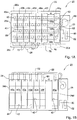
- the data storage system 20 comprises an enclosure 22 which in the present example is a structure comprising a confined space in the form of a storage hall 24 and a support section 25 articulated thereto.
- the storage hall 24 is configured with four side walls 26a to 26d, a door 28 formed in side wall 26c, a ceiling 32 ( Fig. 1B ) and a solid floor 34.
- the present disclosure is a mere example and that the data storage system can in fact be assembled at any suitable location e.g. a confined space or a space within a larger space.
- the floor 34 is fitted with four parallely extending rails 38a to 38d, fixedly articulated thereto. At the event that the data storage system is configured for bearing heavy loads, the floor has to be reinforced, as known in the art.
- cabinets are displaceable over rails
- other locomotive configurations can be facilitated, such as wheels, grooves, magnetic rails, suspension rails and the like.
- the locomotive system can be configured with a shock observing system for dampening and suppressing possible impact of the cabinets against each other upon displacement thereof.
- Each of cabinets 40a to 40g of the related data storage center is configured with a plurality of racks represented in Fig. 1B by dashed lines designated 42 though better appreciated in Fig. 4 .
- Each of the racks 42 is configured for accommodating a variety of data storage and communication appliances, such as computer memory/storage systems, computer units, servers, communication modules, electric power units, schematically illustrated and collectively referred to hereinafter as DSCA and designated 50 ( Fig. 4 ).
- the racks 42 are configured with a plurality of data ports and power sockets for articulation to the DSACs and preferably, such ports and sockets are quick-release type couplings.
- the racks 42 can be modular (as far as height, couplings, sockets etc.), i.e. can be easily modified in size so as to accommodate different DSACs.
- each of the cabinets 40a to 40g extend to a communications port 72 and power port 74, which ports are in communication with a main communications line (dash-doted line 76 in Fig. 1A ) and a main power line 78 (dashed line 78 in Fig. 1A ), which respectively extend into the support section 25 to a central communication facility 80 and a central power backup 82.
- a main communications line dashed line 76 in Fig. 1A
- main power line 78 dashex line 78 in Fig. 1A
- data communication to/from the DSACs, and power supply to the DSACs can be facilitated by flexible cabling.
- data contactors and/or power contactors can be used, so as to facilitate data and power transfer to the cabinets, however without interfering with their mobility within the enclosure and without there occurring any momentarily discontinuities of data communication or power supply.
- the cabinets 40a to 40g are configured with an environmental control system comprising at least a cooling and or heat evacuating system.
- the environmental control system associated with each of the cabinets 40a to 40g is a flexible fluid conduit 60 (e.g. bellows type conduit etc.) branching from supply lines 62 and which extend to a central air cooling unit 66 disposed at the support section 25.
- the flexible piping 62 renders the displaceable cabinets with controlled climate in spite their displacement.
- the support section 25 can be disposed at any location in the vicinity of the data storage system.
- the environmental control system can comprise in addition to cooling units, or instead, heat extractors, heat changers, other types of heat control units such as thermoelectric (peltier) units, etc., and combinations thereof,
- additional one or more environmental controls can be associated with each of the cabinets, such as temperature and humidity controls, etc.
- air treating units such as drying units, purifying/filtering units, etc. can be installed.
- the enclosure or each cabinet can be fitted with a variety of sensors of sensing and controlling the environmental parameters, and additional parameters such as quake sensors, smoke/fire detectors and suppressors 69a and 69b ( Fig. 4 ).
- Figs. 1A and 1B the cabinets are disposed as follows: end cabinets 40a and 40g are stationary and are thus disposed in proximity to the respective side walls 26b and 26d. Cabinets 40b to 40f are all disposed to the left, in close proximity to cabinet 40a and in close proximity to one another, thereby giving rise to a floating isle gap G extending between cabinet 40f and cabinet 40g.
- FIG. 1C the cabinets 40d to 40f are displaced all the way to the left, in close proximity to cabinet 40g and in close proximity to one another, thereby giving rise to a floating isle gap G, now extending between cabinet 40c and cabinet 40d.
- the arrangement is such that the utilization of a given floor space within the given enclosure 22 is substantially increased by avoiding redundant isle space between each two neighboring cabinets, and instead a floating isle gap G is configured. Accordingly, where the length L ( Fig. 1C ) and width Wi of each cabinet 40a to 40g are given, the parameter that can be altered is the redundant isle space between the cabinets, now eliminated and replaced by the floating isle gap G which is exposed between any two neighboring cabinets, or between an end cabinet and a neighboring side wall, to facilitate access and service to the DSCAs mounted on the racks 42 of the side of the duty cabinet facing the floating isle gap.
- the width of the enclosure 22 is substantially equal to the effective width W Eff .
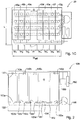
- FIG. 2 of the drawing there is schematically illustrated a further example of a related data storage system generally designated 120.
- the enclosure 122 accommodates n cabinets (four in the schematic example; designated 140a to 140d ) slidable over support rails (not shown). It is appreciated that the principal of a floating isle gap G is maintained, whereby the servicing isle now extending between cabinets 140c and 140d can extend between any of the cabinets or between one of the end cabinets ( 140a or 140d ) and a respective side wall.
- the cabinets are displaceable over a 'floating floor' 134 and wherein a controlled air duct 162 is disposed under said floor 134, extending from a central air treating and cooling unit 166 towards a plurality of ports 163a to 163e, each extending in register with a potential address (location) of a cabinet.
- the arrangement is such that each port is configured with a selectively sealable gate 165.
- ports 163a to 163c and port 163e extend opposite and in register with corresponding inlet openings of the respective cabinets 140a to 140c and 140d, whilst gate 165 of unoccupied port 163d is shut, namely at the location of the floating isle gap G. it is appreciated that according to another configuration, the unoccupied port 163d can remain open and thus contribute to controlling temperature within the enclosure.
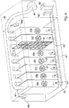
- FIG. 3 illustrates an example of a data storage system according to a preferred embodiment of the present invention generally designated 220 wherein an enclosure 222 is configured with six cabinets 240a to 240f, of which endmost cabinets 240a and 240f are stationary and extend in proximity to side walls of the enclosure.
- Cabinets 240b to 240e are displaceable along parallel rails 238 following the principal disclosed hereinabove, namely floating isle gap G is maintained, whereby the servicing isle now extending between cabinets 240d and 240e, though it can extend between any two cabinets or between one of the end cabinets and a respective side wall.
- cabinets 240c and 240d are segmented, namely each composed of two sub compartments A and B and are each positioned, at the currently illustrated position, over transverse paired rails 237a to 237d.
- This arrangement renders displacing segments A or B of a respective cabinet along the transverse rails 237a to 237d, thus facilitating servicing access to intermediate portions of the respective cabinets 240c and 240d.
- each of the cabinets is configured with the same features as discussed hereinabove, namely temperature and environmental control, communications coupling and power supply, etc.
Description
- The present subject matter is concerned with a data storage system. More particularly, the disclosure is directed to a space saving data storage system.
- Storage data centers are facilities used to house computer storage systems and associated components such as data communications connections, power supplies and environmental controls, namely air conditioning, humidity control, fire/smoke detection and suppression systems, various security devices, shake detection and suppression, etc. Data centers are ever-growing and storage space is becoming a serious issue. There is thus a need for a new storage system and method.
-
JPH11225835A US6 845721B1 relates to a shelving system having mobile shelf units and a wire track embedded in the ground for use in the shelving system.US2013032310A1 relates to cooling system for a Transportable Environmentally Controlled Equipment Enclosure (TECEE) or other equipment enclosure containing racks of heat-generating equipment.US2008239659A1 relates to data processing system storage unit and a cooling system thereof.US2012300398A1 relates to a multi-rack door mounted heat exchanger. - Object of the present invention is to provide a data storage center as defined in claim 1.
- According to one aspect of the presently disclosed subject matter, there is provided a data storage center comprising a plurality of cabinets configured with one or more racks. The racks are configured for accommodating one or more appliances. At least one of said cabinets is displaceable to facilitate access to the respective racks of said cabinet and to racks of a neighboring cabinet of said cabinets.
- The term appliance/appliances as used herein in the specification and claims denotes any form of data storage and communication equipment.
- The arrangement is such that a duty service aisle extends neighboring a selected cabinet and is configured for servicing same, i.e. facilitating access to install/remove and service the data storage and communication appliances.
- According to a primary object of the present disclosure there is a data storage center with an improved volume/storage ratio, i.e. maximizing storage capacity within a given space by eliminating multiple aisles between cabinets, or substantially reducing the number of such aisles, thereby improving utilization of a given floor space.
- A data storage center according to the present disclosure can be installed within any enclosure, i.e. any structure either stationary or mobile, e.g. mountable for locomoting.
- The term rack as used hereinafter in the specification and claims denotes a shelf like compartment for supporting and electrically coupling data storage and communication appliances.
- The term data storage and communication appliances as used hereinafter in the specification and claims denotes computer memory/storage systems, computer units, servers, communication modules, electric power units, etc.
- The term floating isle gap as used hereinafter in the specification and claims denotes the maximal space between two neighboring cabinets, said space facilitating servicing the data storage center and communication appliances supported within said two neighboring cabinets. The floating isle gap can also extend between end cabinets within the enclosure, namely between a wall of the enclosure and a neighboring cabinet.
- The term environmental control as used hereinafter in the specification and claims denotes at least a temperature controlling system. However, environmental control can include also humidity governing systems, air purifying systems, etc.
- According to a particular example of the present disclosure there is provided a data storage center comprising a confined space accommodating a plurality of parallely disposed cabinets and configured with an array of racks which in turn are configured for accommodating a plurality of data storage and communication appliances; at least some of the cabinets are displaceable within the confined space, with at least a floating isle gap between neighboring cabinets extending within the confined space; wherein one or more of the cabinets is associated with a data communications, electric power supply and environmental controls.
- The arrangement is such that the utilization of a given floor space within a given confined space can be dramatically increased by minimizing isle space required between each two cabinets to a floating isle gap (a so-called duty isle gap, or s duty service isle). Accordingly, where the length and width of each cabinet are given, the parameter that can be altered is the redundant isle space between the cabinets, which can be eliminated and replaced by the floating isle gap which is exposed between two neighboring cabinets, or between an end cabinet and a neighboring wall, to facilitate access and service to the data storage and communication appliances mounted on the racks of the side of the duty cabinet/s facing the floating isle gap.
- Thus, where an enclosure is fitted with a plurality of parallel disposed cabinets, each of particular height, width and length, the effective width (WEff ) of the cabinets is:

- Wi denotes the width of cabinet i;
- W' denotes the width of a floating isle gap, namely a maximal gap between two neighboring cabinets;
- n denotes the number of parallel disposed cabinets within the enclosure.
- Any one or more of the following features, design and configurations can be associated with a data storage center according to the present disclosure, separately or in combinations thereof:
- The cabinets can be configured for displacement within the enclosure either manually or motorized;
- The cabinets can be displaceable over parallely disposed rails within the enclosure; the cabinets can be displaceable parallel to one another;
- The cabinets can be configured with a dampening system for reducing shocks imparted to the cabinets upon collision with neighboring cabinets and/or shakes;
- The dampening system can be associated with the cabinets and or with a rail/track system supporting the cabinets;
- The environmental controls can be configured with a temperature controlling system (in particular a cooling system);
- The environmental controls can be configured with a humidity control system;
- The environmental controls can be configured with an air filtration system;
- Each of the cabinets is articulated with an environmental controls, wherein climate controlling fluid flow can take place through a conduit associated with a respective cabinet;
- The enclosure can be configured with additional environmental controls, irrespective of those articulated with the cabinets;
- The climate controlling fluid flow conduit can be fixedly articulated with a cabinet and thus be configured for displacing along with the respective cabinet;
- The climate controlling fluid flow conduit can be a stationary flow port extending from the enclosure and configured for engaging with a respective pickup flow port of a respective cabinet;
- The climate controlling unit associated with each cabinet can be independent or part of a central system;
- The stationary flow port can be configured for shut off at the event that a cabinet is disengaged therefrom;
- Each cabinet can be configured with one or more climate control systems, depending on the amount of heat generated by the data storage and communication appliances mounted on a respective cabinet;
- The storage data center can be configured with a plurality of climate controlling sensors associated with the enclosure and/or with one or more of the cabinets, so as to monitor environmental parameters such as temperature, humidity, purity of the air, etc.;
- The storage data center can be configured with fire/smoke detectors and with a fire suppression arrangement;
- The cabinets can be configured with an anti-static arrangement;
- The storage data center can be configured with an air filtering/purifying system;
- The enclosure can be configured with one or more floating isle gaps along the length of the enclosure;
- The floating isle gap has a width being substantially similar to the width of a rack of a cabinet. Accordingly, where a cabinet is a two sided cabinet (i.e. comprising storage racks at both sides thereof) the width of the gap corresponds substantially with half the width of the respective cabinet. Where the rack extends substantially the width of the cabinet, the width of the gap corresponds substantially with the width of the respective cabinet;
- Where the rack extends substantially along the width of the cabinet, the data storage and communication appliances can be accessed from one side or from both sides of the cabinet;
- Electric supply to the data storage and communication appliances can be through fixed wiring/cabling coupled to the cabinets, contactors, current collector, and the like;
- Data communications of the data storage and communication appliances can be facilitated through fixed wiring articulated with each cabinet;
- Data communications of the data storage and communication appliances can be facilitated through contactors [data port collectors];
- Data communications of the data storage and communication appliances can be facilitated through wireless communication;
- For practical reasons, the arrangement can be such that more than one floating isle gap is provided for a given number of cabinets, e.g. in case of large enclosures, and the like;
- A cabinet may be segmented about its length, where segments of a cabinet can be locomoted jointly, as an integral unit, or each segment individually;
- Some of the cabinets can be segmented and configured for displacing in a so-called side-to-side relation, i.e. along the length of the cabinet;
- The cabinets can be locomoted over a trail/rack system articulated to the floor and/or suspended from the ceiling of the enclosure;
- The racks can be configured with snap coupling ports for fast coupling/detaching of the data storage and communication appliances.
- In order to better understand the subject matter that is disclosed herein and to exemplify how it may be carried out in practice, embodiments will now be described, by way of non-limiting examples only, with reference to the accompanying drawings, in which:
-
Fig. 1A is a schematic top view of a data storage center according to a related data storage center; -
Fig. 1B is a schematic side view of the data storage center ofFig. 1A ; -
Fig. 1C is a schematic top view of the storage data center ofFig. 1A , some cabinets of which are displaced; -
Fig. 2 is a schematic side view of a storage data center according to another example of the present disclosure; and -
Fig. 3 is a schematic top view of a storage data center according to yet another example of the present disclosure; and -
Fig. 4 is perspective representation of a storage data center according to the present disclosure. - Attention is directed first to
Figs. 1A to 1C of the drawings, directed to a related data storage system generally designated 20. - The
data storage system 20 comprises anenclosure 22 which in the present example is a structure comprising a confined space in the form of astorage hall 24 and asupport section 25 articulated thereto. Thestorage hall 24 is configured with fourside walls 26a to 26d, adoor 28 formed inside wall 26c, a ceiling 32 (Fig. 1B ) and asolid floor 34. - It is appreciated that the present disclosure is a mere example and that the data storage system can in fact be assembled at any suitable location e.g. a confined space or a space within a larger space.
- The
floor 34 is fitted with four parallely extendingrails 38a to 38d, fixedly articulated thereto. At the event that the data storage system is configured for bearing heavy loads, the floor has to be reinforced, as known in the art. - It is further appreciated that whilst in the particular example the cabinets are displaceable over rails, other locomotive configurations can be facilitated, such as wheels, grooves, magnetic rails, suspension rails and the like.
- Noting the sensitive nature of the gear mounted on the racks, it is noted that the locomotive system can be configured with a shock observing system for dampening and suppressing possible impact of the cabinets against each other upon displacement thereof.
- Each of
cabinets 40a to 40g of the related data storage center is configured with a plurality of racks represented inFig. 1B by dashed lines designated 42 though better appreciated inFig. 4 . Each of theracks 42 is configured for accommodating a variety of data storage and communication appliances, such as computer memory/storage systems, computer units, servers, communication modules, electric power units, schematically illustrated and collectively referred to hereinafter as DSCA and designated 50 (Fig. 4 ). Theracks 42 are configured with a plurality of data ports and power sockets for articulation to the DSACs and preferably, such ports and sockets are quick-release type couplings. Theracks 42 can be modular (as far as height, couplings, sockets etc.), i.e. can be easily modified in size so as to accommodate different DSACs. - The data ports and power sockets of each of the
cabinets 40a to 40g extend to acommunications port 72 andpower port 74, which ports are in communication with a main communications line (dash-dotedline 76 inFig. 1A ) and a main power line 78 (dashedline 78 inFig. 1A ), which respectively extend into thesupport section 25 to acentral communication facility 80 and acentral power backup 82. - It is appreciated that data communication to/from the DSACs, and power supply to the DSACs can be facilitated by flexible cabling. Alternatively, data contactors and/or power contactors can be used, so as to facilitate data and power transfer to the cabinets, however without interfering with their mobility within the enclosure and without there occurring any momentarily discontinuities of data communication or power supply.
- Noting the nature of the DSCAs, namely electric components emitting considerable heat and requiring cooling system for maintain their proper operation, the
cabinets 40a to 40g are configured with an environmental control system comprising at least a cooling and or heat evacuating system. In the example ofFigs. 1A to 1C , the environmental control system associated with each of thecabinets 40a to 40g is a flexible fluid conduit 60 (e.g. bellows type conduit etc.) branching fromsupply lines 62 and which extend to a centralair cooling unit 66 disposed at thesupport section 25. Theflexible piping 62 renders the displaceable cabinets with controlled climate in spite their displacement. It is noted that thesupport section 25 can be disposed at any location in the vicinity of the data storage system. - It is appreciated that according to other configurations (not illustrated) the environmental control system can comprise in addition to cooling units, or instead, heat extractors, heat changers, other types of heat control units such as thermoelectric (peltier) units, etc., and combinations thereof,
- Furthermore, it is appreciated that additional one or more environmental controls can be associated with each of the cabinets, such as temperature and humidity controls, etc. Also, air treating units such as drying units, purifying/filtering units, etc. can be installed. In addition, the enclosure or each cabinet can be fitted with a variety of sensors of sensing and controlling the environmental parameters, and additional parameters such as quake sensors, smoke/fire detectors and
suppressors Fig. 4 ). - In
Figs. 1A and 1B , the cabinets are disposed as follows:end cabinets respective side walls Cabinets 40b to 40f are all disposed to the left, in close proximity tocabinet 40a and in close proximity to one another, thereby giving rise to a floating isle gap G extending betweencabinet 40f andcabinet 40g. - Turning now to
Fig. 1C , thecabinets 40d to 40f are displaced all the way to the left, in close proximity tocabinet 40g and in close proximity to one another, thereby giving rise to a floating isle gap G, now extending betweencabinet 40c andcabinet 40d. - The arrangement is such that the utilization of a given floor space within the given
enclosure 22 is substantially increased by avoiding redundant isle space between each two neighboring cabinets, and instead a floating isle gap G is configured. Accordingly, where the length L (Fig. 1C ) and width Wi of eachcabinet 40a to 40g are given, the parameter that can be altered is the redundant isle space between the cabinets, now eliminated and replaced by the floating isle gap G which is exposed between any two neighboring cabinets, or between an end cabinet and a neighboring side wall, to facilitate access and service to the DSCAs mounted on theracks 42 of the side of the duty cabinet facing the floating isle gap. - Thus, where an
enclosure 22 is fitted with a plurality of parallel disposed cabinets, each of particular height, width and length, the effective width ( WEff ) of the cabinets is:
- Wi denotes the width of cabinet i;
- W' denotes the width of a floating isle gap, namely a maximal gap between two neighboring cabinets;
- n denotes the number of parallel disposed cabinets within the enclosure.
- The width of the
enclosure 22 is substantially equal to the effective width WEff. - It is appreciated that according to the present example five isles have been eliminated (assuming the
tow end cabinets - Turning now to
Fig. 2 of the drawing, there is schematically illustrated a further example of a related data storage system generally designated 120. - The
enclosure 122 accommodates n cabinets (four in the schematic example; designated 140a to 140d) slidable over support rails (not shown). It is appreciated that the principal of a floating isle gap G is maintained, whereby the servicing isle now extending betweencabinets - However, in the present example the cabinets are displaceable over a 'floating floor' 134 and wherein a controlled
air duct 162 is disposed under saidfloor 134, extending from a central air treating andcooling unit 166 towards a plurality ofports 163a to 163e, each extending in register with a potential address (location) of a cabinet. The arrangement is such that each port is configured with a selectivelysealable gate 165. In the illustratedposition ports 163a to 163c andport 163e extend opposite and in register with corresponding inlet openings of therespective cabinets 140a to 140c and 140d, whilstgate 165 ofunoccupied port 163d is shut, namely at the location of the floating isle gap G. it is appreciated that according to another configuration, theunoccupied port 163d can remain open and thus contribute to controlling temperature within the enclosure. - In addition to the above, all communications between the
central communication facility 180 and thecabinets 163a to 163e (namely with the DSCAs mounted over the racks in the cabinets), as well as connectivity with the central power andbackup unit 182 takes place bycontactors 193 engaged with communication and power lines schematically represented by line 195. - The schematic representation of
Fig. 3 illustrates an example of a data storage system according to a preferred embodiment of the present invention generally designated 220 wherein an enclosure 222 is configured with sixcabinets 240a to 240f, of whichendmost cabinets Cabinets 240b to 240e are displaceable alongparallel rails 238 following the principal disclosed hereinabove, namely floating isle gap G is maintained, whereby the servicing isle now extending betweencabinets - However, in the present example,
cabinets rails 237a to 237d. This arrangement renders displacing segments A or B of a respective cabinet along thetransverse rails 237a to 237d, thus facilitating servicing access to intermediate portions of therespective cabinets
Claims (15)
- A data storage center (220) comprising a plurality of cabinets (240a-240f) configured with one or more racks, said racks being configured for accommodating one or more appliances; characterized in that at least one (240c, 240d) of said cabinets (240a-240f) is displaceable in a first direction, and in a second direction perpendicular to the first direction, over a transverse rail system (238, 237a-237d), to facilitate access to the respective racks of said cabinet (240c, 240d) and to racks of a neighboring cabinet of said cabinets (240c, 240d).
- A data storage center (220) according to Claim 1, further comprising an enclosure (122) defining a confined space in which said cabinets (240a-240f) are disposed.
- A data storage center (220) according to Claim 2, wherein at least one of said cabinets (240a-240f) is displaceable in the first direction within said confined space so that a floating isle gap (G) between each two neighboring cabinets is formed within the confined space.
- A data storage center (220) according to Claim 3, wherein said cabinets (240a-240f) are parallel with respect to each other and each having a width Wi, said floating isle gap (G) having a width W', and wherein an effective width (WEff ) of the cabinets (240a-240f) is:

- A data storage center (220) according to Claim 4, wherein a width of said confined space is substantially equal to WEff .
- A data storage center (220) according to Claim 4 or 5, wherein the width Wi is identical in all the cabinets (240a-240f) and is substantially equal to width W'.
- A data storage center (220) according to any one of the preceding claims, further comprising environmental controls associated with at least one of said cabinets (240a-240f) for providing environmental control to the appliances (50) thereof.
- A data storage center (220) according to Claim 7, wherein the environmental controls comprise at least one of: a temperature controlling system, a humidity control system, and an air filtration system.
- A data storage center (220) according to Claim 7 or 8, wherein said association with at least one of said cabinets (240a-240f) is provided by a climate controlling fluid flow conduit (60) articulated thereto.
- A data storage center (220) according to Claim 9, when dependent on Claim 2, wherein the climate controlling fluid flow conduit (60) is a stationary flow port extending from the enclosure (122) and configured for engaging with a respective pickup flow port of a respective cabinet of said cabinets (240a-240f).
- A data storage center (220) according to Claim 9, wherein said climate controlling fluid flow conduit (60) is displaceable with its respective cabinet.
- A data storage center (220) according to any one of the preceding claims, when dependent on Claim 2, further comprising a plurality of climate controlling sensors (69a, 69b) associated with the enclosure (122) or with one or more of the cabinets (240a-240f), so as to monitor environmental parameters such as temperature, humidity, and purity of air.
- A data storage center (220) according to any one of the preceding claims, further comprising data communications (180) associated with said cabinets (240a-240f) for providing data communication to the appliances (50) of the cabinet (240a-240f).
- A data storage center (220) according to Claim 13, wherein the data communications (80, 180) is facilitated through fixed wiring articulated with said cabinets (240a-240f) or through wireless communication.
- A data storage center (220) according to any one of the preceding claims, wherein at least part of the cabinets (240c, 240d) is segmented.
Applications Claiming Priority (2)
| Application Number | Priority Date | Filing Date | Title |
|---|---|---|---|
| US201462054030P | 2014-09-23 | 2014-09-23 | |
| PCT/IL2015/050950 WO2016046816A1 (en) | 2014-09-23 | 2015-09-20 | Data storage system |
Publications (3)
| Publication Number | Publication Date |
|---|---|
| EP3197317A1 EP3197317A1 (en) | 2017-08-02 |
| EP3197317A4 EP3197317A4 (en) | 2018-05-23 |
| EP3197317B1 true EP3197317B1 (en) | 2021-07-28 |
Family
ID=55580409
Family Applications (1)
| Application Number | Title | Priority Date | Filing Date |
|---|---|---|---|
| EP15843139.5A Active EP3197317B1 (en) | 2014-09-23 | 2015-09-20 | Data storage system |
Country Status (8)
| Country | Link |
|---|---|
| US (1) | US10609837B2 (en) |
| EP (1) | EP3197317B1 (en) |
| JP (1) | JP2017537371A (en) |
| CN (1) | CN107249387B (en) |
| AU (1) | AU2015323351B2 (en) |
| IL (1) | IL251322A0 (en) |
| SG (2) | SG11201702346YA (en) |
| WO (1) | WO2016046816A1 (en) |
Families Citing this family (7)
| Publication number | Priority date | Publication date | Assignee | Title |
|---|---|---|---|---|
| SG11201702346YA (en) * | 2014-09-23 | 2017-04-27 | Storone Ltd | Data storage system |
| US10334762B2 (en) * | 2015-01-29 | 2019-06-25 | Hewlett Packard Enterprise Development Lp | Movable rack |
| US10853460B2 (en) * | 2017-12-04 | 2020-12-01 | Vapor IO Inc. | Modular data center |
| CN109598865A (en) * | 2018-12-28 | 2019-04-09 | 顺丰科技有限公司 | It automatically moves express delivery cabinet, automatically move express delivery cabinet system and control method |
| US11295135B2 (en) * | 2020-05-29 | 2022-04-05 | Corning Research & Development Corporation | Asset tracking of communication equipment via mixed reality based labeling |
| US11374808B2 (en) | 2020-05-29 | 2022-06-28 | Corning Research & Development Corporation | Automated logging of patching operations via mixed reality based labeling |
| CN113453496B (en) * | 2021-05-25 | 2022-06-28 | 广东培正学院 | Gateway data storage server cabinet for big data platform |
Family Cites Families (52)
| Publication number | Priority date | Publication date | Assignee | Title |
|---|---|---|---|---|
| US865268A (en) * | 1907-02-26 | 1907-09-03 | Henry Lee Powell | Display-rack for metal bedsteads. |
| US4307922A (en) * | 1980-03-13 | 1981-12-29 | Reflector-Hardware Corporation | Movable storage system |
| US4723819A (en) * | 1986-06-12 | 1988-02-09 | Shoe Spa Inc. | Merchandizing device |
| US5160189A (en) * | 1990-04-03 | 1992-11-03 | Automated Storage & Retrieval Systems Of America | Automatic locking device for movable shelving |
| US5057977A (en) * | 1990-04-17 | 1991-10-15 | Triangle Pacific Corp. | Pull-out lighted display |
| GB2257966B (en) * | 1991-04-26 | 1994-08-31 | Daifuku Kk | Rack arrangement |
| US5924779A (en) * | 1996-11-01 | 1999-07-20 | Wenger Corporation | Music library system |
| US5967346A (en) * | 1997-04-18 | 1999-10-19 | Engineered Data Products, Incorporated | Supplemental storage rack system for expansion of storage capacity of high density storage rack system |
| JPH11225835A (en) | 1998-02-16 | 1999-08-24 | Purosasu:Kk | Moving server rack |
| US6112917A (en) * | 1998-11-23 | 2000-09-05 | Denstor Mobile Storage Systems, Inc. | Moveable file storage supporting apparatus |
| US6241106B1 (en) * | 1999-04-19 | 2001-06-05 | Erecta International Corporation | Movable shelf |
| US6739463B2 (en) * | 2001-05-25 | 2004-05-25 | L&P Property Management Company | Modular rack conversion apparatus and method |
| CN1464770A (en) | 2002-06-13 | 2003-12-31 | 民盈电讯有限公司 | Box-type data center infrastructure and container type data center |
| US6845721B1 (en) * | 2003-11-10 | 2005-01-25 | Montel Inc. | Ground embedded wire tracks for a shelving system having mobile shelf units |
| US20060082263A1 (en) * | 2004-10-15 | 2006-04-20 | American Power Conversion Corporation | Mobile data center |
| JP4674667B2 (en) | 2005-06-30 | 2011-04-20 | コクヨ株式会社 | Security unit and mobile rack device |
| US7652889B2 (en) | 2005-10-25 | 2010-01-26 | Hewlett-Packard Development Company, L.P. | Information technology (IT) equipment position locating system using jumper connections |
| US7724513B2 (en) * | 2006-09-25 | 2010-05-25 | Silicon Graphics International Corp. | Container-based data center |
| US8783051B2 (en) | 2007-04-02 | 2014-07-22 | Hewlett-Packard Development Company, L.P. | Data processing system storage unit, data processing system cooling apparatus and data processing system |
| US20090229194A1 (en) * | 2008-03-11 | 2009-09-17 | Advanced Shielding Technologies Europe S.I. | Portable modular data center |
| JP5344459B2 (en) * | 2008-06-30 | 2013-11-20 | インターナショナル・ビジネス・マシーンズ・コーポレーション | Control device, control method, and control program |
| JP4648966B2 (en) * | 2008-08-19 | 2011-03-09 | 日立電線株式会社 | Data center |
| US7852627B2 (en) * | 2008-10-31 | 2010-12-14 | Dell Products L.P. | System and method for high density information handling system enclosure |
| US8733812B2 (en) | 2008-12-04 | 2014-05-27 | Io Data Centers, Llc | Modular data center |
| US8264840B2 (en) * | 2009-05-15 | 2012-09-11 | NxGen Modular, LLC | Modular data center and associated methods |
| GB2467808B (en) * | 2009-06-03 | 2011-01-12 | Moduleco Ltd | Data centre |
| US8031468B2 (en) * | 2009-06-03 | 2011-10-04 | American Power Conversion Corporation | Hot aisle containment cooling unit and method for cooling |
| CN101815423B (en) | 2010-01-11 | 2012-06-27 | 浪潮(北京)电子信息产业有限公司 | Method and device for cooling machine cabinet |
| JP5185319B2 (en) * | 2010-05-14 | 2013-04-17 | 株式会社東芝 | Air conditioning system and air conditioning control method for server room management |
| CN201700121U (en) | 2010-06-18 | 2011-01-05 | 中国移动通信集团设计院有限公司 | Cabinet and blowing system |
| WO2012083166A2 (en) * | 2010-12-16 | 2012-06-21 | Smartcube, Llc | Portable computer server enclosure |
| US8804334B2 (en) | 2011-05-25 | 2014-08-12 | International Business Machines Corporation | Multi-rack, door-mounted heat exchanger |
| US8827090B2 (en) * | 2011-07-18 | 2014-09-09 | Holland Storage Systems Llc | Three-dimensional storage system |
| BR112013033723A2 (en) | 2011-07-26 | 2017-01-31 | Firetrace Usa Llc | data center hot row / cold row fire suppression methods and apparatus |
| EP2555605A1 (en) | 2011-08-01 | 2013-02-06 | GSI Helmholtzzentrum für Schwerionenforschung GmbH | Mobile data centre unit with efficient cooling means |
| US20130032310A1 (en) | 2011-08-02 | 2013-02-07 | Power Distribution Inc. | Transportable, environmentally-controlled equipment enclosure |
| TWI439205B (en) * | 2011-08-30 | 2014-05-21 | Hon Hai Prec Ind Co Ltd | Rack mechanism for server |
| US9161638B2 (en) * | 2011-10-17 | 2015-10-20 | Schlage Lock Company Llc | Retail merchandising platform |
| WO2013056787A1 (en) * | 2011-10-21 | 2013-04-25 | Rittal Gmbh & Co. Kg | Cooling circuit system, especially for use in a computing center and corresponding control method |
| JP2013149905A (en) | 2012-01-23 | 2013-08-01 | Fujitsu Fsas Inc | Rack system |
| CN103260362A (en) * | 2012-02-17 | 2013-08-21 | 鸿富锦精密工业(深圳)有限公司 | Server cabinet and combination thereof |
| CN102625622B (en) | 2012-04-13 | 2015-05-27 | 上海银音信息科技有限公司 | Container data center |
| JP2014006574A (en) | 2012-06-21 | 2014-01-16 | Renesas Electronics Corp | Calculator device |
| JP2014215918A (en) * | 2013-04-26 | 2014-11-17 | 富士通株式会社 | Movement mechanism and rack housing structure |
| JP6325103B2 (en) * | 2013-08-09 | 2018-05-16 | サーム−オー−ディスク・インコーポレイテッド | Wireless temperature and / or humidity sensor assembly |
| CN203722985U (en) * | 2013-12-27 | 2014-07-16 | 联方云天科技(北京)有限公司 | A container type data center |
| SG11201702346YA (en) * | 2014-09-23 | 2017-04-27 | Storone Ltd | Data storage system |
| US9451823B2 (en) * | 2015-01-08 | 2016-09-27 | Swingstow, Llc | Adjustable shelving system |
| US9414672B1 (en) * | 2015-03-10 | 2016-08-16 | Michael Flynn | Adjustable overhead storage system |
| US9826833B2 (en) * | 2015-11-27 | 2017-11-28 | Ijang Industrial Co., Ltd. | Rack assembly and sub-rack thereof |
| CA3024466C (en) * | 2016-05-20 | 2021-03-30 | 560 Holdings, LLC | Modular pallet racking system |
| US9795062B1 (en) * | 2016-06-29 | 2017-10-17 | Amazon Technologies, Inc. | Portable data center for data transfer |
-
2015
- 2015-09-20 SG SG11201702346YA patent/SG11201702346YA/en unknown
- 2015-09-20 WO PCT/IL2015/050950 patent/WO2016046816A1/en active Application Filing
- 2015-09-20 JP JP2017516765A patent/JP2017537371A/en active Pending
- 2015-09-20 SG SG10201902622PA patent/SG10201902622PA/en unknown
- 2015-09-20 AU AU2015323351A patent/AU2015323351B2/en not_active Ceased
- 2015-09-20 CN CN201580055383.5A patent/CN107249387B/en active Active
- 2015-09-20 US US15/513,531 patent/US10609837B2/en active Active
- 2015-09-20 EP EP15843139.5A patent/EP3197317B1/en active Active
-
2017
- 2017-03-21 IL IL251322A patent/IL251322A0/en unknown
Non-Patent Citations (1)
| Title |
|---|
| None * |
Also Published As
| Publication number | Publication date |
|---|---|
| IL251322A0 (en) | 2017-05-29 |
| US20170251567A1 (en) | 2017-08-31 |
| EP3197317A4 (en) | 2018-05-23 |
| US10609837B2 (en) | 2020-03-31 |
| SG11201702346YA (en) | 2017-04-27 |
| AU2015323351B2 (en) | 2019-12-05 |
| WO2016046816A1 (en) | 2016-03-31 |
| AU2015323351A1 (en) | 2017-04-27 |
| CN107249387B (en) | 2020-07-21 |
| SG10201902622PA (en) | 2019-04-29 |
| EP3197317A1 (en) | 2017-08-02 |
| JP2017537371A (en) | 2017-12-14 |
| CN107249387A (en) | 2017-10-13 |
Similar Documents
| Publication | Publication Date | Title |
|---|---|---|
| EP3197317B1 (en) | Data storage system | |
| US9258930B2 (en) | Expandable data center with side modules | |
| EP2308279B1 (en) | Building for a computer centre with devices for efficient cooling | |
| US7944692B2 (en) | Method and apparatus for installation and removal of overhead cooling equipment | |
| US20160348360A1 (en) | Expandable data center with movable wall | |
| US9848516B2 (en) | Liquid-assisted bottom air cooling of electronic racks in data centers | |
| US20180024608A1 (en) | Flexible Power Support Redundancy Busway System | |
| KR101873264B1 (en) | Expandable data center with movable wall | |
| WO2016070280A1 (en) | Smart mission critical rack | |
| US20040132398A1 (en) | Integrated cabinet for containing electronic equipment | |
| US10206311B2 (en) | Cooling circuit system, in particular to be used in a data center, and controlling method thereof | |
| GB2467808B (en) | Data centre | |
| EP2998961A1 (en) | Chassis input/output (i/o) module for use in front region of mass storage chassis assembly | |
| US10939588B2 (en) | Airflow distribution and management architecture for large data center | |
| EP2074337B1 (en) | Operation ready transportable data center in a shipping container | |
| US9888608B2 (en) | Electronics structure comprising at least one barrier impermeable to fine particles | |
| US10334762B2 (en) | Movable rack | |
| JP5427836B2 (en) | Container type data center |
Legal Events
| Date | Code | Title | Description |
|---|---|---|---|
| STAA | Information on the status of an ep patent application or granted ep patent |
Free format text: STATUS: THE INTERNATIONAL PUBLICATION HAS BEEN MADE |
|
| PUAI | Public reference made under article 153(3) epc to a published international application that has entered the european phase |
Free format text: ORIGINAL CODE: 0009012 |
|
| STAA | Information on the status of an ep patent application or granted ep patent |
Free format text: STATUS: REQUEST FOR EXAMINATION WAS MADE |
|
| 17P | Request for examination filed |
Effective date: 20170331 |
|
| AK | Designated contracting states |
Kind code of ref document: A1 Designated state(s): AL AT BE BG CH CY CZ DE DK EE ES FI FR GB GR HR HU IE IS IT LI LT LU LV MC MK MT NL NO PL PT RO RS SE SI SK SM TR |
|
| AX | Request for extension of the european patent |
Extension state: BA ME |
|
| DAV | Request for validation of the european patent (deleted) | ||
| DAX | Request for extension of the european patent (deleted) | ||
| A4 | Supplementary search report drawn up and despatched |
Effective date: 20180419 |
|
| RIC1 | Information provided on ipc code assigned before grant |
Ipc: H05K 7/14 20060101ALI20180413BHEP Ipc: A47B 53/02 20060101AFI20180413BHEP Ipc: H05K 7/20 20060101ALI20180413BHEP |
|
| STAA | Information on the status of an ep patent application or granted ep patent |
Free format text: STATUS: EXAMINATION IS IN PROGRESS |
|
| 17Q | First examination report despatched |
Effective date: 20200207 |
|
| GRAP | Despatch of communication of intention to grant a patent |
Free format text: ORIGINAL CODE: EPIDOSNIGR1 |
|
| STAA | Information on the status of an ep patent application or granted ep patent |
Free format text: STATUS: GRANT OF PATENT IS INTENDED |
|
| INTG | Intention to grant announced |
Effective date: 20210125 |
|
| RAP1 | Party data changed (applicant data changed or rights of an application transferred) |
Owner name: STORONE LTD. |
|
| GRAS | Grant fee paid |
Free format text: ORIGINAL CODE: EPIDOSNIGR3 |
|
| GRAA | (expected) grant |
Free format text: ORIGINAL CODE: 0009210 |
|
| STAA | Information on the status of an ep patent application or granted ep patent |
Free format text: STATUS: THE PATENT HAS BEEN GRANTED |
|
| AK | Designated contracting states |
Kind code of ref document: B1 Designated state(s): AL AT BE BG CH CY CZ DE DK EE ES FI FR GB GR HR HU IE IS IT LI LT LU LV MC MK MT NL NO PL PT RO RS SE SI SK SM TR |
|
| REG | Reference to a national code |
Ref country code: GB Ref legal event code: FG4D |
|
| REG | Reference to a national code |
Ref country code: CH Ref legal event code: EP |
|
| REG | Reference to a national code |
Ref country code: AT Ref legal event code: REF Ref document number: 1413917 Country of ref document: AT Kind code of ref document: T Effective date: 20210815 |
|
| REG | Reference to a national code |
Ref country code: IE Ref legal event code: FG4D |
|
| REG | Reference to a national code |
Ref country code: DE Ref legal event code: R096 Ref document number: 602015071784 Country of ref document: DE |
|
| REG | Reference to a national code |
Ref country code: LT Ref legal event code: MG9D |
|
| REG | Reference to a national code |
Ref country code: NL Ref legal event code: MP Effective date: 20210728 |
|
| REG | Reference to a national code |
Ref country code: AT Ref legal event code: MK05 Ref document number: 1413917 Country of ref document: AT Kind code of ref document: T Effective date: 20210728 |
|
| PG25 | Lapsed in a contracting state [announced via postgrant information from national office to epo] |
Ref country code: HR Free format text: LAPSE BECAUSE OF FAILURE TO SUBMIT A TRANSLATION OF THE DESCRIPTION OR TO PAY THE FEE WITHIN THE PRESCRIBED TIME-LIMIT Effective date: 20210728 Ref country code: SE Free format text: LAPSE BECAUSE OF FAILURE TO SUBMIT A TRANSLATION OF THE DESCRIPTION OR TO PAY THE FEE WITHIN THE PRESCRIBED TIME-LIMIT Effective date: 20210728 Ref country code: RS Free format text: LAPSE BECAUSE OF FAILURE TO SUBMIT A TRANSLATION OF THE DESCRIPTION OR TO PAY THE FEE WITHIN THE PRESCRIBED TIME-LIMIT Effective date: 20210728 Ref country code: LT Free format text: LAPSE BECAUSE OF FAILURE TO SUBMIT A TRANSLATION OF THE DESCRIPTION OR TO PAY THE FEE WITHIN THE PRESCRIBED TIME-LIMIT Effective date: 20210728 Ref country code: AT Free format text: LAPSE BECAUSE OF FAILURE TO SUBMIT A TRANSLATION OF THE DESCRIPTION OR TO PAY THE FEE WITHIN THE PRESCRIBED TIME-LIMIT Effective date: 20210728 Ref country code: BG Free format text: LAPSE BECAUSE OF FAILURE TO SUBMIT A TRANSLATION OF THE DESCRIPTION OR TO PAY THE FEE WITHIN THE PRESCRIBED TIME-LIMIT Effective date: 20211028 Ref country code: PT Free format text: LAPSE BECAUSE OF FAILURE TO SUBMIT A TRANSLATION OF THE DESCRIPTION OR TO PAY THE FEE WITHIN THE PRESCRIBED TIME-LIMIT Effective date: 20211129 Ref country code: NO Free format text: LAPSE BECAUSE OF FAILURE TO SUBMIT A TRANSLATION OF THE DESCRIPTION OR TO PAY THE FEE WITHIN THE PRESCRIBED TIME-LIMIT Effective date: 20211028 Ref country code: NL Free format text: LAPSE BECAUSE OF FAILURE TO SUBMIT A TRANSLATION OF THE DESCRIPTION OR TO PAY THE FEE WITHIN THE PRESCRIBED TIME-LIMIT Effective date: 20210728 Ref country code: ES Free format text: LAPSE BECAUSE OF FAILURE TO SUBMIT A TRANSLATION OF THE DESCRIPTION OR TO PAY THE FEE WITHIN THE PRESCRIBED TIME-LIMIT Effective date: 20210728 Ref country code: FI Free format text: LAPSE BECAUSE OF FAILURE TO SUBMIT A TRANSLATION OF THE DESCRIPTION OR TO PAY THE FEE WITHIN THE PRESCRIBED TIME-LIMIT Effective date: 20210728 |
|
| PG25 | Lapsed in a contracting state [announced via postgrant information from national office to epo] |
Ref country code: PL Free format text: LAPSE BECAUSE OF FAILURE TO SUBMIT A TRANSLATION OF THE DESCRIPTION OR TO PAY THE FEE WITHIN THE PRESCRIBED TIME-LIMIT Effective date: 20210728 Ref country code: LV Free format text: LAPSE BECAUSE OF FAILURE TO SUBMIT A TRANSLATION OF THE DESCRIPTION OR TO PAY THE FEE WITHIN THE PRESCRIBED TIME-LIMIT Effective date: 20210728 Ref country code: GR Free format text: LAPSE BECAUSE OF FAILURE TO SUBMIT A TRANSLATION OF THE DESCRIPTION OR TO PAY THE FEE WITHIN THE PRESCRIBED TIME-LIMIT Effective date: 20211029 |
|
| PG25 | Lapsed in a contracting state [announced via postgrant information from national office to epo] |
Ref country code: DK Free format text: LAPSE BECAUSE OF FAILURE TO SUBMIT A TRANSLATION OF THE DESCRIPTION OR TO PAY THE FEE WITHIN THE PRESCRIBED TIME-LIMIT Effective date: 20210728 |
|
| REG | Reference to a national code |
Ref country code: DE Ref legal event code: R097 Ref document number: 602015071784 Country of ref document: DE |
|
| REG | Reference to a national code |
Ref country code: CH Ref legal event code: PL |
|
| REG | Reference to a national code |
Ref country code: BE Ref legal event code: MM Effective date: 20210930 |
|
| PG25 | Lapsed in a contracting state [announced via postgrant information from national office to epo] |
Ref country code: SM Free format text: LAPSE BECAUSE OF FAILURE TO SUBMIT A TRANSLATION OF THE DESCRIPTION OR TO PAY THE FEE WITHIN THE PRESCRIBED TIME-LIMIT Effective date: 20210728 Ref country code: SK Free format text: LAPSE BECAUSE OF FAILURE TO SUBMIT A TRANSLATION OF THE DESCRIPTION OR TO PAY THE FEE WITHIN THE PRESCRIBED TIME-LIMIT Effective date: 20210728 Ref country code: RO Free format text: LAPSE BECAUSE OF FAILURE TO SUBMIT A TRANSLATION OF THE DESCRIPTION OR TO PAY THE FEE WITHIN THE PRESCRIBED TIME-LIMIT Effective date: 20210728 Ref country code: MC Free format text: LAPSE BECAUSE OF FAILURE TO SUBMIT A TRANSLATION OF THE DESCRIPTION OR TO PAY THE FEE WITHIN THE PRESCRIBED TIME-LIMIT Effective date: 20210728 Ref country code: EE Free format text: LAPSE BECAUSE OF FAILURE TO SUBMIT A TRANSLATION OF THE DESCRIPTION OR TO PAY THE FEE WITHIN THE PRESCRIBED TIME-LIMIT Effective date: 20210728 Ref country code: CZ Free format text: LAPSE BECAUSE OF FAILURE TO SUBMIT A TRANSLATION OF THE DESCRIPTION OR TO PAY THE FEE WITHIN THE PRESCRIBED TIME-LIMIT Effective date: 20210728 Ref country code: AL Free format text: LAPSE BECAUSE OF FAILURE TO SUBMIT A TRANSLATION OF THE DESCRIPTION OR TO PAY THE FEE WITHIN THE PRESCRIBED TIME-LIMIT Effective date: 20210728 |
|
| PLBE | No opposition filed within time limit |
Free format text: ORIGINAL CODE: 0009261 |
|
| STAA | Information on the status of an ep patent application or granted ep patent |
Free format text: STATUS: NO OPPOSITION FILED WITHIN TIME LIMIT |
|
| 26N | No opposition filed |
Effective date: 20220429 |
|
| PG25 | Lapsed in a contracting state [announced via postgrant information from national office to epo] |
Ref country code: LU Free format text: LAPSE BECAUSE OF NON-PAYMENT OF DUE FEES Effective date: 20210920 Ref country code: IT Free format text: LAPSE BECAUSE OF FAILURE TO SUBMIT A TRANSLATION OF THE DESCRIPTION OR TO PAY THE FEE WITHIN THE PRESCRIBED TIME-LIMIT Effective date: 20210728 Ref country code: IE Free format text: LAPSE BECAUSE OF NON-PAYMENT OF DUE FEES Effective date: 20210920 Ref country code: BE Free format text: LAPSE BECAUSE OF NON-PAYMENT OF DUE FEES Effective date: 20210930 |
|
| PG25 | Lapsed in a contracting state [announced via postgrant information from national office to epo] |
Ref country code: LI Free format text: LAPSE BECAUSE OF NON-PAYMENT OF DUE FEES Effective date: 20210930 Ref country code: CH Free format text: LAPSE BECAUSE OF NON-PAYMENT OF DUE FEES Effective date: 20210930 |
|
| PGFP | Annual fee paid to national office [announced via postgrant information from national office to epo] |
Ref country code: GB Payment date: 20220920 Year of fee payment: 8 Ref country code: DE Payment date: 20220927 Year of fee payment: 8 |
|
| PGFP | Annual fee paid to national office [announced via postgrant information from national office to epo] |
Ref country code: FR Payment date: 20220926 Year of fee payment: 8 |
|
| PG25 | Lapsed in a contracting state [announced via postgrant information from national office to epo] |
Ref country code: HU Free format text: LAPSE BECAUSE OF FAILURE TO SUBMIT A TRANSLATION OF THE DESCRIPTION OR TO PAY THE FEE WITHIN THE PRESCRIBED TIME-LIMIT; INVALID AB INITIO Effective date: 20150920 |
|
| PG25 | Lapsed in a contracting state [announced via postgrant information from national office to epo] |
Ref country code: CY Free format text: LAPSE BECAUSE OF FAILURE TO SUBMIT A TRANSLATION OF THE DESCRIPTION OR TO PAY THE FEE WITHIN THE PRESCRIBED TIME-LIMIT Effective date: 20210728 |