EP3197302B1 - Machine for making smokers' articles - Google Patents
Machine for making smokers' articles Download PDFInfo
- Publication number
- EP3197302B1 EP3197302B1 EP15775810.3A EP15775810A EP3197302B1 EP 3197302 B1 EP3197302 B1 EP 3197302B1 EP 15775810 A EP15775810 A EP 15775810A EP 3197302 B1 EP3197302 B1 EP 3197302B1
- Authority
- EP
- European Patent Office
- Prior art keywords
- smokers
- articles
- tobacco
- conveyor
- machine according
- Prior art date
- Legal status (The legal status is an assumption and is not a legal conclusion. Google has not performed a legal analysis and makes no representation as to the accuracy of the status listed.)
- Active
Links
Images



Classifications
-
- A—HUMAN NECESSITIES
- A24—TOBACCO; CIGARS; CIGARETTES; SIMULATED SMOKING DEVICES; SMOKERS' REQUISITES
- A24C—MACHINES FOR MAKING CIGARS OR CIGARETTES
- A24C5/00—Making cigarettes; Making tipping materials for, or attaching filters or mouthpieces to, cigars or cigarettes
- A24C5/36—Removing papers or other parts from defective cigarettes
Definitions
- the numeral 1 denotes a unit for recovering tobacco from rejected products in machines for making smokers' articles, in particular cigarettes “S” according to this invention.
- cigarettes “S” in particular filter-tipped cigarettes.
- the roller 101 is preferably provided on its periphery with a plurality of flutes, typically suction flutes, which hold the cigarettes “S” in position.
- the one or more rollers 101 are designed to transport the smokers' articles “S” towards an outfeed conveyor 105 located at an end section of the machine 100.
- the width of the conveyor is substantially equal to the length of the cigarette to be broken down/recovered.
- the nozzle 8 is movable at least partly in synchrony with the conveyor means 2 to act on the cigarette "S" along at least one stretch of predetermined length (not on a point) in order to better empty the main portion "S1".
- the blade 13 has at least one active position in which it protrudes above the conveyor means 2.
- the tobacco inside the main portion "S1" is blown or sucked out in such a way as to empty the paper wrapper.
Landscapes
- Manufacturing Of Cigar And Cigarette Tobacco (AREA)
Description
- This invention relates to a machine for making smoker's articles and comprising a unit for recovering tobacco from rejected products in said machine. Hereinafter in this description, reference is made, by way of example only and without losing in generality, to smokers' articles such as cigarettes.
- During the production of cigarettes, the total number of cigarettes made inevitably includes defective cigarettes among the cigarettes which meet accepted standards of quality. In light of this, cigarette making machines are equipped with numerous checking devices by which each cigarette is tested for conformity to specifications. In effect, it is necessary, for example, to check that every cigarette made contains the right quantity of tobacco, that there is enough tobacco at the end opposite the filter to make that end sufficiently compact to prevent the tobacco from falling out, that the paper wrapped around the tobacco is correctly glued and is not torn or stained, and so on.
- Cigarettes found to be defective are rejected at specific expulsion stations, thus becoming reject products, and are collected, usually in specific containers, and then transferred to specific machines especially designed to recover the tobacco from them.
- In these machines, the defective cigarettes are crushed or the paper is cut lengthways by a blade, and the different cigarette parts (filter, paper and tobacco) are separated. The filters and paper are scrapped, whereas the tobacco is recovered and then re-used in cigarette making machines.
- There are numerous examples of machines of the above mentioned type for recovering tobacco from defective cigarettes and publications
EP2289356A1 ,EP0990395A1 andUS5000196A , for example, describe three different types. - The machines concerned are usually relatively complex and expensive. Also, their use has major negative aspects in terms of wasted time and energy in that the defective cigarettes must be collected, transferred to the machine which crushes them and separates out the different materials they are made of, and the tobacco recovered must be stored and then taken to the cigarette making machine which re-uses it.
- Moreover, crushing the cigarettes or cutting the paper with a blade inevitably deteriorates the quality of the tobacco recovered, which is broken up into very short fibres containing a large amount of dust and which is therefore not very suitable for making good quality cigarettes. Another prior art machine is disclosed in document
EP2730182 , which describes a tobacco recovery unit in which cutting means first cut off the filter from the body of the cigarette and blowing means then extract the tobacco from the tubular wrap of the cigarette. - Disadvantageously, the solution described in
EP2730182 has numerous drawbacks, connected mainly with the high level of tobacco loss and the difficulty of combining the continuous movement of the conveyor with the efficiency of emptying the cigarette. DocumentWO2013/064352 discloses a machine for making smoking articles such as cigarettes that include filters, for use in recovering smokeable material from the smoking articles rejected during manufacture. - This invention therefore has for an aim to provide machines for making smokers' articles to overcome the disadvantages described above with reference to the prior art.
- More specifically, the aim of this invention is to provide a machine for making smokers' articles having a unit for recovering tobacco from rejected products and capable of maximizing the degree of material recovery.
- Another aim of the invention is to provide a unit for recovering tobacco from rejected products and which operates in-process and at high speeds. These aims are achieved by a machines for making smokers' articles, having the features described in one or more of the appended claims and, more specifically, comprising conveyor means configured to move a sequence of smokers' articles along a direction transversal to their axes of extension between a pickup position and a disposal position, at least one tobacco recovery channel and at least one reject collector for the scrap materials (paper and filters).
- According to the invention, the unit comprises a cutting unit operatively interposed between the pickup position and the disposal position and configured to separate the main portion from the filter of each smokers' article and pneumatic means operatively located along the conveyor means and configured to generate a negative pressure or an overpressure at at least one smokers' article along the conveyor means in order to extract the tobacco from the main portion, where the pneumatic means are associated with the tobacco recovery channel.
- Advantageously, thanks to the unit of this invention, it is possible to recover the tobacco without subjecting the tobacco to any mechanical or crushing action, while the reject materials (paper and filters) are separated and disposed of in specific, dedicated containers (or collectors).
- Further features and advantages of the invention are more apparent from the following exemplary and therefore non-limiting description of a preferred and hence non-exclusive embodiment of a unit and a method for recovering tobacco from rejected products in machines for making smokers' articles, as illustrated in the accompanying drawings, in which:
-
Figure 1 shows a side view of a machine for making smokers' articles comprising a unit for recovering tobacco from rejected products according to this invention; -
Figure 2 shows a schematic view of a first embodiment of a unit for recovering tobacco from rejected products according to this invention; -
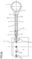
Figure 2a shows a side view of a detail fromFigure 2 . -
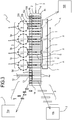
Figure 3 shows a schematic view of a second embodiment of a unit for recovering tobacco from rejected products according to this invention; -
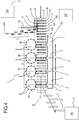
Figure 4 shows a schematic view of a third embodiment of a unit for recovering tobacco from rejected products according to this invention; -
Figure 5 shows a schematic view of a fourth embodiment of a unit for recovering tobacco from rejected products according to this invention; -
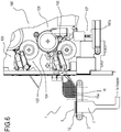
Figure 6 shows a side view of a further preferred embodiment of a machine for making smokers' articles comprising a unit for recovering tobacco from rejected products according to this invention; -
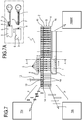
Figure 7 shows a schematic view of the tobacco recovery unit of the machine ofFigure 6 ; -
Figure 7a shows a schematic view of a detail fromFigure 7 in two different operating conditions. - With reference to the accompanying drawings, the
numeral 1 denotes a unit for recovering tobacco from rejected products in machines for making smokers' articles, in particular cigarettes "S" according to this invention. Hereinafter, reference is made, by way of example only and hence without losing in generality, to smokers' articles such as cigarettes "S", in particular filter-tipped cigarettes. - As this description continues, therefore, reference will be made to "cigarette" or "smokers' article" without distinction and in the most general sense of the term.
- Each cigarette "S" (or smokers' article) extends along its main axis "A" of extension and comprises at least a main portion "S1" and a filter "F" positioned in series along the axis "A".
- The main portion "S1" is basically a paper wrapper containing a predetermined quantity of tobacco.
- The
recovery unit 1 according to the invention is associated with amachine 100 for making smokers' articles, in particular a filter tip attachment machine, that is to say, a machine configured to combine (in essentially known manner) a filter "F" with the corresponding main portion "S1" of each cigarette "S". - The
machine 100 thus comprises at least one combining station (not illustrated), where each filter "F" is combined with the respective main portion "S1" and then transported by one ormore movement rollers 101 towards anoutfeed section 102 of themachine 100. - The
roller 101 is preferably provided on its periphery with a plurality of flutes, typically suction flutes, which hold the cigarettes "S" in position. The one ormore rollers 101 are designed to transport the smokers' articles "S" towards anoutfeed conveyor 105 located at an end section of themachine 100. - Preferably, along the outfeed path, the machine is also provided with inspection means 103 for checking the quality of each cigarette "S".
- For example, the inspection means 103 are configured to check the degree of ventilation of each cigarette "S" or that the end opposite the filter tip contains the right quantity tobacco or that the paper wrapped around the tobacco is correctly glued and is not torn or soiled. Operatively downstream of the inspection means 103, the machine comprises at least one
selector element 104 configured to pick out the defective smokers' articles and to divert them away from the path defined by the one ormore rollers 101. - Preferably, the
selector element 104 is configured to distinguish between defective smokers' articles of a first type, which are recoverable, and defective smokers' articles of a second type, which are difficult to recover. Defective smokers' articles of the first type are preferably substantially complete cigarettes with ventilation or insufficient tobacco defects. Defective smokers' articles of the second type, on the other hand, are smokers' articles at an intermediate processing stage, damaged, for example, by malfunctions or jams, such that their components (paper wrapper, filter, tobacco) are difficult to distinguish. - In light of this, with reference in particular to
Figure 6 , theselector element 104 comprises detecting and rejecting means 106 configured to reject the defective smokers' articles of the second type and convey them to a release ordumping zone 107. Preferably, the release ordumping zone 107 comprises aconveyor 107a or chute designed to direct such rejects into specific containers without returning them to the production process. - More specifically, the
selector element 104 is operatively interposed between the inspection means 103 and theconveyor 105. - Preferably, therefore, the
unit 1 for recovering tobacco from rejected products according to this invention is operatively located downstream of theselector element 104. - The
unit 1 comprises conveyor means 2 configured to move a sequence of smokers' articles "S" along a direction transversal to their axes "A" of extension between a pickup position and a disposal position. - More specifically, the pickup position is preferably located in proximity to the
selector element 104 of themachine 100, while the disposal position is located at at least onespecific reject collector 3.. - It should be noted that in this text, the term "reject" is used to denote those parts of the cigarette "S" (or of the smokers' articles) which are not recovered or returned to the production process, such as, for example, the filters "F" and the paper wrappers "P" of the main portions "S1". Preferably, the conveyor means 2 comprise at least one
conveyor belt 4 provided with a plurality oftransversal grooves 4a arranged in sequence and each defining a housing for a respective smokers' article or cigarette "S". - In the embodiment illustrated, the conveyor means 2 comprise two facing
conveyor belts 4, opposite to each other in such a way as to define a section for the passage of the smokers' articles, delimited both above and below the cigarette "S". - Thus, the
conveyor belts 4 move at the same speed and synchronously so that eachtransversal groove 4a of one belt faces and is superposed on a correspondingtransversal groove 4a on theother belt 4. - Preferably, the
unit 1 comprises at least one accumulation unit 16 (orhopper 16a) located just downstream of theselector element 104 and configured to define a buffer zone for the cigarettes "S" to be rejected. - It is thus advantageously possible to keep the operating speed of the
unit 1 independent of that of themachine 100 to allow for peak workloads (when production of rejected products is at its highest). - The conveyor means 2 preferably also comprise at least one
retaining device 5 for retaining at least one of the cigarettes "S". - The
retaining device 5 is configured to prevent (or limit) the sliding of the cigarette "S" along its axis "A". - In the preferred embodiment, the retaining
device 5 is a suction unit (not illustrated in detail) associated with eachtransversal groove 4a of at least one of theconveyor belts 4. Alternatively, the retainingdevice 5 might be a pusher which moves towards and away from the filter "F" of the cigarette (seeFigure 7a ). - Alternatively, the retaining
device 5 might be embodied by theconveyor belts 4 themselves, spaced from each other by a gap which is smaller than the maximum transversal dimension (i.e. diameter) of the cigarette "S". - In other words, in this embodiment, the cigarettes "S" are held in position by compression, preferably applied at the filter "F".
- Preferably, the
unit 1 also comprises pneumatic means 6 operatively located along the conveyor means 2 and configured to generate a negative pressure or an overpressure at at least one smokers' article "S" along the conveyor means 2 in order to extract the tobacco T from the main portion "S1". - Thus, the pneumatic means 6 are located along the conveyor means 2, laterally thereof, in such a way as to face a free end of the cigarette "S".
- Preferably, the
conveyor belts 4 are a little larger in width than a cigarette "S" in order to minimize the distance which the tobacco must travel after it has been blown or sucked out by the pneumatic means, thereby limiting tobacco loss. - More preferably, the width of the conveyor is substantially equal to the length of the cigarette to be broken down/recovered.
- In the preferred embodiment, the pneumatic means 6 are located laterally of the conveyor means 2 so that, at least at an operating position thereof, they face the end of the cigarette "S" provided with the filter "F".
- Thus, in the preferred embodiment, the pneumatic means 6 comprise a blowing device 6a configured to generate an overpressure inside the cigarette "S" to facilitate removal of the tobacco.
- In this embodiment, the
unit 1 also comprises atobacco recovery channel 7 located on the side opposite to theconveyors 2 relative to the pneumatic means 6. - In other words, in the embodiment illustrated, the pneumatic means 6 and the
recovery channel 7 are located on opposite sides of the conveyor means, with reference to the feed direction of the conveyors. - Alternatively (or in addition to), in some embodiments not illustrated, the pneumatic means 6 comprise a suction unit juxtaposed with the conveyor means 2 so that, at least at an operating position thereof, they face the free end of the main portion "S1" of the cigarette "S".
- It should be noted that in this embodiment, the
recovery channel 7 is located on the same side of the pneumatic means 6 as the conveyor means 2. - Whatever the case, in both of the embodiments described above, the pneumatic means 6 are associated with the
tobacco recovery channel 7. - The
recovery channel 7 is configured to transport the tobacco recovered by therecovery unit 1 to a feed station (not illustrated) where the tobacco, not processed in any way and therefore suitable for making another cigarette "S" is fed back into themachine 100. - Thus, the
recovery channel 7 is preferably in fluid communication with, or otherwise connected to, the hopper (not illustrated) of themachine 100. Advantageously, the tobacco is thus recovered in-process, maximizing recovery efficiency and minimizing operator involvement. - It should be noted that the retaining
device 5 described above is particularly useful and effective when used in combination with the pneumatic means 6 because it allows maximizing the blowing and/or sucking action without affecting the position of the cigarette "S". - Thus, the retaining
device 5 is operatively located precisely at least at the pneumatic means 6 so as to keep the cigarette "S" in place during the blowing or sucking action of the pneumatic means 6. - Preferably, however, the retaining
device 5 operates along the whole of theconveyor belt 4. - As regards the pneumatic means 6, these preferably comprise at least one
blowing nozzle 8 located laterally of theconveyor 2 and having at least one operating position where it faces the filter "F" of a cigarette "S" in order to generate an overpressure inside the cigarette "S" itself so as to allow tobacco to be extracted from the main portion "S1". - It should be noted that in some embodiments (
Figure 4 ) the nozzle might face a mouth of the main portion "S1" of the smokers' article "S", where the mouth corresponds to the end opposite the free end, which in use is connected to the filter "F". - Thus, in the operating position, the
nozzle 8 is substantially coaxial with aflute 4a of the conveyor belt in order to optimize the blowing action. - Preferably, the
nozzle 8 is movable at least partly in synchrony with the conveyor means 2 to act on the cigarette "S" along at least one stretch of predetermined length (not on a point) in order to better empty the main portion "S1". - In other words, during the forward motion of the
conveyor belt 4, and thus of theflutes 4a, thenozzle 8 is movable in the same direction as thebelt 4 from an attached position, where it at least partly faces a respective flute to start blowing, to a detached position by way of an intermediate position of maximum efficiency where thenozzle 8 is fully coaxial with theflute 4a (and thus with the cigarette "S"). - To increase the productivity of the
unit 1 to make it compatible with the high production capacities of machines which make smokers' articles, the pneumatic means 6 comprise preferably at least onerotatable drum 9 equipped with a plurality of blowingnozzles 8, angularly spaced from each other, each having at least one operating position where it (laterally) faces the conveyor means 2. - Advantageously, the rotational motion of the
drum 9 makes the movement of thenozzles 8 less critical in structural terms (reciprocating motion would certainly place more stress on the structure on account of speed). In the preferred embodiments (Figures 2 ,3 ,4 ), the pneumatic means 6 comprise a plurality ofrotatable drums 9 mounted in sequence along the conveyor means 2 (that is, along the feed direction "B") in order to generate an overpressure at a corresponding plurality of cigarettes "S". Advantageously, the unit can thus operate simultaneously on a plurality of cigarettes "S" either individually or in different runs whereby a cigarette partly emptied by one nozzle is "finished" by the next nozzle. - In light of this, the
recovery unit 1 comprises a control unit (not illustrated) configured to synergically combine the movement of theconveyor belt 2 with that of thedrums 9 depending on the operating mode preferred by the operator. - More specifically, the unit has at least two operating modes.
- In the first operating mode, shown in
Figure 2 , theconveyor belt 4 moves forward in such a way that eachflute 4a faces at least onenozzle 8 of eachdrum 9. - That way, the
nozzle 8 of the first drum 9 (or of the first drums 9) starts the emptying-out action on the main portion "S1", whilst thenozzles 8 after that complete it. - Advantageously, this allows keeping the conveyor means 2 running at high speed without the need for excessively powerful pneumatic means. Alternatively, in the second operating mode, with reference to
Figures 3 and4 , the cigarettes "S" on the conveyor belt can be divided into first (10a), second (10b) and third smokers' articles (10c) arranged in alternating sequence. - At the same time, the plurality of
rotatable drums 9 in turn comprise a first 9a, a second 9b and athird drum 9c which are spaced from each other. The control unit is configured to drive the conveyor means 2 and thedrum 9 in such a way that: - the
first drum 9a, at the predetermined operating position, can be coupled to the first smokers'articles 10a; - the second drum 9b, at the predetermined operating position, can be coupled to the second smokers'
articles 10b; - the
third drum 9c, at the predetermined operating position, can be coupled to the third smokers' articles 10c.; - Advantageously, thanks to this control logic, using relatively high power pneumatic means 6 maximizes the productivity of the
unit 1. - It should also be noted that the example given can be generalized to a different number of
drums 9. - Thus, if there are four drums (a first 9a, a second 9b, a third 9c and a fourth 9d, as shown in
Figures 3 and4 ) the smokers' articles would be divided into a sequence of fours, with first 10a, second 10b, third 10c and fourth smokers'articles 10d. - Consequently, the control logic described here can be summed up by the equation:

- Nt is the number of drums;
- Ng is the number of groups which the sequence of smokers' articles can be divided into.
- It should also be noted that the number of groups corresponds to the distance travelled by the conveyor means 2 between one activation and the next of two
nozzles 8 on thesame drum 9. -
Figure 5 , on the other hand, shows a further embodiment of theunit 1, where there is only onerotatable drum 9 which comprises at least one straight stretch 11a of predetermined length, where eachnozzle 8 is movable in parallel with the conveyor means 2 and faces a respective cigarette "S". - In other words, the
drum 9 has a plurality ofnozzles 8 movable along an annular path having twocurved stretches 11b and at least one straight stretch 11a facing (and parallel to) theconveyor belt 2. - Advantageously, therefore, the pneumatic means 6, and more specifically, the
nozzles 8, can remain active on a single cigarette "S" for a stretch of considerable length, thus maximizing their effect. - Alternatively, if there are less constraints regarding reduced production speed compared to the machines which make the smokers' articles, the
conveyor 2 might be moved intermittently in order to maximize the time the nozzles remain active. - It should be noted that, preferably and with reference to
Figure 7a , thedrum 9 is movable towards and away from theconveyor 2 transversely to the feed direction "B". - Advantageously, that way, the control unit can drive the
drum 9, and hence thenozzle 8, towards the cigarette "S", preferably into contact with the filter "F", in order to maximize the blowing effect. - According to a further aspect of the invention, the
unit 1 comprises a cuttingunit 12 operatively interposed between the pickup position and the disposal position and configured to separate the main portion "S1" from the filter "F" of each smokers' article "S". - Preferably, the cutting
unit 12 comprises at least oneblade 13 oriented along the feed direction "B" of the conveyor means 2. - The
blade 13 is configured to be positioned between the filter "F" and the main portion "S1" in such a way as to separate them. - Preferably, the
blade 13 has at least one active position in which it protrudes above the conveyor means 2. - More specifically, the
conveyor belt 4 has at least oneslot 14 or longitudinal slit which divides it into afirst part 4b and a second part (or half-part) 4c, both extending along the feed direction "B". - More specifically, the
first part 4b is designed to house the main portions "S1" of the cigarettes "S" and thesecond part 4c is designed to house the filters "F" of the cigarettes "S". - The
blade 13 is located at theslot 14 or slit and at least partly protrudes above theconveyor belt 4. - Advantageously, that way, the cutting action on the cigarettes "S" is precise and easy.
- It should be noted that depending on the embodiment, the cutting
unit 12 may be positioned operatively upstream or downstream of the pneumatic means 6. - Preferably, however, the cutting
unit 12 is operatively located downstream of the pneumatic means 6. - Advantageously, it is thus possible for the pneumatic means to act directly on the filter "F" to blow the tobacco out of the main portion "S1" and the cutting unit does not risk damaging the tobacco to be recovered. Moreover, the presence of the filter "F" guarantees the radial grip of the tobacco wrapper, thus preventing tobacco loss and optimizing tobacco recovery. Operatively downstream of the cutting
unit 13, there is, lastly, a rejects 3 - preferably at least two collectors, afirst collector 15a designed to collect the filters "F" and asecond collector 15b designed to collect the paper wrappers of the main portions "S1". - This disclosure also has for an object a method for recovering tobacco from defective cigarettes "S". Preferably but not exclusively, the method is implemented through use of a machine for making smoker's articles comprising the
tobacco recovery unit 1 according to this invention. - The method comprises a step of feeding a sequence of smokers' articles (in particular, cigarettes "S") along a direction transversal to their axes "A" between a pickup position and a disposal position.
- As they are being fed, the smokers' articles are cut in such a way that the main portion "S1" is separated from the filter "F".
- Before or after cutting, the tobacco inside the main portion "S1" is blown or sucked out in such a way as to empty the paper wrapper.
- Preferably, this step comprises blowing through the filter.
- The tobacco extracted from the main portion is recovered, whilst the filter and the paper wrapper are disposed of (separately from each other).
- The invention achieves the above mentioned aims and brings important advantages.
- In effect, the use of a recovery unit capable of extracting the tobacco at high speed without fragmenting it, combined with a cutting unit which can divide the reject materials, makes for an efficient recovery and effective scrap disposal system.
- In effect, the presence of a cutting unit which is independent of tobacco extraction allows the cigarette materials to be separated precisely without, however, any unwanted effects (i.e. fragmentation) on the tobacco fibres which can thus be returned to the process immediately without being damaged.
- Moreover, the use of a movable nozzle (or a plurality of movable nozzles) allows maximizing productivity by speeding up the recovery process.
Claims (14)
- A machine for making smokers' articles, in particular cigarettes, each extending along its main axis (A) of extension and comprising at least a main portion (S1) and a filter (F) positioned in series along the axis (A); the machine comprising:- means for making a sequence of smokers' articles (S);- inspection means (103) for checking the quality of each smokers' article;- at least one outfeed conveyor (105) configured to move the smokers' articles (S) feeding out of the machine (100);- at least one selector element (104) configured to pick out the defective smokers' articles (S); wherein the machine comprises a tobacco recovery unit (1) comprising:- conveyor means (2) configured to move a sequence of smokers' articles (S) along a feed direction (B) transversal to the axis (A) between a pickup position and a disposal position;- at least one tobacco recovery channel (7);- at least one reject collector (3);characterized in that it comprises a cutting unit (12) operatively interposed between the pickup position and the disposal position and configured to separate the main portion (S1) from the filter (F) of each smokers' article (S) and pneumatic means (6) operatively located along the conveyor means (2) and configured to generate a negative pressure or an overpressure at at least one smokers' article (S) along the conveyor means (2) in order to extract the tobacco (T) from the main portion (S1); the pneumatic means (6) being associated with the tobacco recovery channel (7),
wherein the selector element (104) is configured to distinguish between defective smokers' articles of a first type, which are recoverable, and defective smokers' articles of a second type, which are not recoverable. - The machine according to claim 1, characterized in that the selector element (104) comprises detecting and rejecting means (105) configured to reject the defective smokers' articles of the second type and convey them to a release or dumping zone (106).
- The machine according to claim 2, characterized in that the release or dumping zone (106) comprises a conveyor (107) or chute designed to direct the defective smokers' articles of the second type into specific containers without returning them to the production process.
- The machine according to any one of claims 1 to 3, characterized in that it comprises a hopper for collecting the tobacco (T) and operatively located upstream of the means for making a sequence of smokers' articles (S); the recovery channel (7) being in fluid communication with, or in any case connected to, the hopper in order to allow the tobacco to be recovered in-process.
- The machine according to any of the preceding claims, characterized in that the conveyor means (2) comprise at least one conveyor belt (4) provided with a plurality of transversal grooves (4a) arranged in sequence and each defining a housing for a respective smokers' article (S).
- The machine according to any of the preceding claims, characterized in that the conveyor means (2) comprise at least one retaining device (5) for holding down at least one smokers' article (S) and operatively located at least at the pneumatic means (6) in order to hold the smokers' article (S) in place during the suction or blowing action of the pneumatic means (6).
- The machine according to any of the preceding claims, characterized in that the cutting unit (12) comprises at least one blade (13) oriented along the feed direction (B) of the conveyor means (2) and having at least one operating position where it protrudes above the conveyor means (2).
- The machine according to claim 7, characterized in that the conveyor means (2) comprise at least one conveyor belt (4) having a slot (14) or slit which divides the conveyor belt (4) into a first part (4b) for housing the main portion (S1) of the smokers' articles (S), and a second part (4c) for housing the filter (F) of the smokers' articles (S); the blade (14) being located at the slot (14) or slit and at least partly protruding above the conveyor belt (4).
- The machine according to any of the preceding claims, characterized in that the pneumatic means (6) comprise at least one blow nozzle (8) located laterally of the conveyor means (2) and having at least one operating position where it faces the filter (F) or the mouth of the main portion (S1) of a smokers' article (S) to produce an overpressure inside the smokers' article (S) such as to blow the tobacco (T) out of the main portion (S1).
- The machine according to claim 9, characterized in that the at least one nozzle (8) is movable at least partly in synchrony with the conveyor means (2) to act on the smokers' article (S) along at least one stretch of predetermined length so as to better empty out the main portion (S1).
- The machine according to claim 9 or 10, characterized in that the pneumatic means (6) comprise at least one rotatable drum (9) equipped with a plurality of nozzles (8) spaced at equal angular intervals and each having a respective operating position where it laterally faces the conveyor means (2).
- The machine according to claim 11, characterized in that the pneumatic means (6) comprise a plurality of rotatable drums (9) arranged in sequence along the conveyor means (2) in order to produce the overpressure at a corresponding plurality of smokers' articles (S).
- The machine according to claim 12, characterized in that the sequence of smokers' articles (S) comprises first (10a), second (10b) and third smokers' articles (10c) in alternating sequence; the plurality of rotatable drums (9) in turn comprising a first (9a), a second (9b) and a third drum (9c) spaced from each other in such a way that:- the first drum (9a), at the predetermined operating position, can be coupled to the first smokers' articles (10a);- the second drum (9b), at the predetermined operating position, can be coupled to the second smokers' articles (10b);- the third drum (9c), at the predetermined operating position, can be coupled to the third smokers' articles (10c).
- The machine according to claim 11, characterized in that the rotatable drum (9) comprises at least one straight stretch (11a) of predetermined length, where each nozzle (8) is movable in parallel with the conveyor means (2) and faces a respective smokers' article (S).
Priority Applications (1)
| Application Number | Priority Date | Filing Date | Title |
|---|---|---|---|
| PL15775810T PL3197302T3 (en) | 2014-09-26 | 2015-09-07 | Machine for making smokers' articles |
Applications Claiming Priority (2)
| Application Number | Priority Date | Filing Date | Title |
|---|---|---|---|
| ITBO20140528 | 2014-09-26 | ||
| PCT/IB2015/056833 WO2016046678A1 (en) | 2014-09-26 | 2015-09-07 | Unit and method for recovering tobacco from rejected products in machines for making smokers' articles |
Publications (2)
| Publication Number | Publication Date |
|---|---|
| EP3197302A1 EP3197302A1 (en) | 2017-08-02 |
| EP3197302B1 true EP3197302B1 (en) | 2018-11-07 |
Family
ID=52130563
Family Applications (1)
| Application Number | Title | Priority Date | Filing Date |
|---|---|---|---|
| EP15775810.3A Active EP3197302B1 (en) | 2014-09-26 | 2015-09-07 | Machine for making smokers' articles |
Country Status (3)
| Country | Link |
|---|---|
| EP (1) | EP3197302B1 (en) |
| PL (1) | PL3197302T3 (en) |
| WO (1) | WO2016046678A1 (en) |
Families Citing this family (5)
| Publication number | Priority date | Publication date | Assignee | Title |
|---|---|---|---|---|
| CN106418675A (en) * | 2016-12-06 | 2017-02-22 | 常德瑞华制造有限公司 | High-speed tobacco pressing device |
| IT201900014352A1 (en) | 2019-08-08 | 2021-02-08 | Gd Spa | Conveyor and alignment method for rod-shaped items |
| CN111957673A (en) * | 2020-08-25 | 2020-11-20 | 红塔烟草(集团)有限责任公司 | Method and device for absorbing cigarette ash and tobacco powder in on-line cigarette production |
| CN112425817A (en) * | 2020-11-27 | 2021-03-02 | 武汉达汇新科技有限公司 | Waste cigarette and cut tobacco recovery device |
| CN118020995A (en) * | 2024-03-19 | 2024-05-14 | 红云红河烟草(集团)有限责任公司 | Online tobacco shred recycling control method and device for defective cigarettes removed by cigarette making machine |
Family Cites Families (11)
| Publication number | Priority date | Publication date | Assignee | Title |
|---|---|---|---|---|
| US3757799A (en) * | 1972-01-26 | 1973-09-11 | Rothmans Of Pall Mall | Tobacco reclaiming method and apparatus |
| US4117852A (en) * | 1976-08-31 | 1978-10-03 | Philip Morris Incorporated | Method and apparatus for reclaiming tobacco from cigarettes |
| US4763673A (en) * | 1985-02-04 | 1988-08-16 | R. J. Reynolds Tobacco Company | Method and apparatus for ejecting tobacco from filter cigarettes |
| DE3839431A1 (en) | 1988-11-23 | 1990-05-31 | Fr Niepmann Gmbh U Co Maschf | METHOD AND DEVICE FOR RECOVERY TOBACCO FROM DEFECTIVE CIGARETTES |
| DE19844815A1 (en) | 1998-09-30 | 2000-04-13 | Universelle Eng U N I Gmbh | Device for cutting rod-shaped articles in the tobacco processing industry |
| DE102005024780A1 (en) * | 2005-05-31 | 2006-12-14 | Jacobi Systemtechnik Gmbh | Assembly to extract tobacco from faulty cigarettes, for recovery, has a drum to hold fixed cigarettes in mantle openings and a second drum with blower mouthpieces to blow the tobacco from the paper tubes |
| DE102009037686A1 (en) | 2009-08-18 | 2011-03-17 | Hauni Maschinenbau Ag | Device for processing smoking article waste |
| CN102689702A (en) * | 2011-03-23 | 2012-09-26 | 昆明市凯跃机电塑料有限责任公司 | Novel waste cigarette removing device for cigarette machine |
| GB201118728D0 (en) * | 2011-10-31 | 2011-12-14 | British American Tobacco Co | Smokeable material recovery |
| EP2730183B1 (en) * | 2012-11-08 | 2018-05-02 | Köhl Maschinenbau AG | Device and method for reclaiming tobacco from smoking articles |
| EP2730182A3 (en) | 2012-11-08 | 2015-04-08 | Köhl Maschinenbau AG | Device and method for recovering of smoking article parts from smoking articles |
-
2015
- 2015-09-07 WO PCT/IB2015/056833 patent/WO2016046678A1/en not_active Ceased
- 2015-09-07 PL PL15775810T patent/PL3197302T3/en unknown
- 2015-09-07 EP EP15775810.3A patent/EP3197302B1/en active Active
Non-Patent Citations (1)
| Title |
|---|
| None * |
Also Published As
| Publication number | Publication date |
|---|---|
| WO2016046678A1 (en) | 2016-03-31 |
| EP3197302A1 (en) | 2017-08-02 |
| PL3197302T3 (en) | 2019-05-31 |
Similar Documents
| Publication | Publication Date | Title |
|---|---|---|
| EP2978325B1 (en) | Method and a machine for making cigarettes, with recovery of tobacco from defective cigarettes | |
| EP3197302A1 (en) | Unit and method for recovering tobacco from rejected products in machines for making smokers' articles | |
| US3224451A (en) | Apparatus for removal of tips from scrap cigarettes | |
| EP2750525B1 (en) | Tobacco reclaim from waste cigarettes | |
| EP2773228B1 (en) | Smokeable material recovery | |
| GB2494159A (en) | Cigarette processing assembly for reclaiming tobacco | |
| US5001951A (en) | Apparatus for cutting apart cigarette packs in preparation for recovery of the tobacco in the cigarettes | |
| US4117852A (en) | Method and apparatus for reclaiming tobacco from cigarettes | |
| US5117843A (en) | Method of and apparatus for reclaiming tobacco from cigarette packages | |
| US3233613A (en) | Method and apparatus for reclaiming defective cigarette assemblies and the like | |
| WO2014135913A1 (en) | Method and apparatus for the recovery of tobacco from cigarettes with filter | |
| EP3114945B1 (en) | Disassembly device and disassembly method for smokers' articles | |
| EP1334036B1 (en) | A method and a device for the rejection of commodities | |
| US5234007A (en) | Method of and apparatus for reclaiming tobacco from cigarette packages | |
| CN214826418U (en) | Hollow filter stick transferring and conveying assembly | |
| KR100331389B1 (en) | Apparatus and method used for unpacking of packaged goods | |
| CN104013099A (en) | Cleaning of a machine for the tobacco processing industry | |
| US6769435B2 (en) | Cigarette maker outfeed unit | |
| CN117530487A (en) | A pneumatic cutting type processing device for exploding waste cigarette smoke | |
| CN1317987C (en) | Device and a method for separating at least one continuous rod of forming material for tobacco products | |
| CN1954733B (en) | Apparatus for feeding filters | |
| RU2776519C2 (en) | Retrofitting device, instrument for manufacture of multi-segment rods and method for manufacture of multi-segment rods | |
| EP4570083B1 (en) | A device for separating a multi-segment rod-like article of tobacco industry | |
| CN1739414B (en) | Apparatus for feeding filters | |
| CN118303662A (en) | Cigarette recovery device |
Legal Events
| Date | Code | Title | Description |
|---|---|---|---|
| STAA | Information on the status of an ep patent application or granted ep patent |
Free format text: STATUS: THE INTERNATIONAL PUBLICATION HAS BEEN MADE |
|
| PUAI | Public reference made under article 153(3) epc to a published international application that has entered the european phase |
Free format text: ORIGINAL CODE: 0009012 |
|
| STAA | Information on the status of an ep patent application or granted ep patent |
Free format text: STATUS: REQUEST FOR EXAMINATION WAS MADE |
|
| 17P | Request for examination filed |
Effective date: 20170406 |
|
| AK | Designated contracting states |
Kind code of ref document: A1 Designated state(s): AL AT BE BG CH CY CZ DE DK EE ES FI FR GB GR HR HU IE IS IT LI LT LU LV MC MK MT NL NO PL PT RO RS SE SI SK SM TR |
|
| AX | Request for extension of the european patent |
Extension state: BA ME |
|
| DAV | Request for validation of the european patent (deleted) | ||
| DAX | Request for extension of the european patent (deleted) | ||
| GRAP | Despatch of communication of intention to grant a patent |
Free format text: ORIGINAL CODE: EPIDOSNIGR1 |
|
| STAA | Information on the status of an ep patent application or granted ep patent |
Free format text: STATUS: GRANT OF PATENT IS INTENDED |
|
| INTG | Intention to grant announced |
Effective date: 20180502 |
|
| GRAS | Grant fee paid |
Free format text: ORIGINAL CODE: EPIDOSNIGR3 |
|
| GRAA | (expected) grant |
Free format text: ORIGINAL CODE: 0009210 |
|
| STAA | Information on the status of an ep patent application or granted ep patent |
Free format text: STATUS: THE PATENT HAS BEEN GRANTED |
|
| AK | Designated contracting states |
Kind code of ref document: B1 Designated state(s): AL AT BE BG CH CY CZ DE DK EE ES FI FR GB GR HR HU IE IS IT LI LT LU LV MC MK MT NL NO PL PT RO RS SE SI SK SM TR |
|
| REG | Reference to a national code |
Ref country code: GB Ref legal event code: FG4D |
|
| REG | Reference to a national code |
Ref country code: CH Ref legal event code: EP Ref country code: AT Ref legal event code: REF Ref document number: 1061041 Country of ref document: AT Kind code of ref document: T Effective date: 20181115 |
|
| REG | Reference to a national code |
Ref country code: DE Ref legal event code: R096 Ref document number: 602015019616 Country of ref document: DE |
|
| REG | Reference to a national code |
Ref country code: IE Ref legal event code: FG4D |
|
| REG | Reference to a national code |
Ref country code: NL Ref legal event code: FP |
|
| REG | Reference to a national code |
Ref country code: LT Ref legal event code: MG4D |
|
| REG | Reference to a national code |
Ref country code: AT Ref legal event code: MK05 Ref document number: 1061041 Country of ref document: AT Kind code of ref document: T Effective date: 20181107 |
|
| PG25 | Lapsed in a contracting state [announced via postgrant information from national office to epo] |
Ref country code: LT Free format text: LAPSE BECAUSE OF FAILURE TO SUBMIT A TRANSLATION OF THE DESCRIPTION OR TO PAY THE FEE WITHIN THE PRESCRIBED TIME-LIMIT Effective date: 20181107 Ref country code: NO Free format text: LAPSE BECAUSE OF FAILURE TO SUBMIT A TRANSLATION OF THE DESCRIPTION OR TO PAY THE FEE WITHIN THE PRESCRIBED TIME-LIMIT Effective date: 20190207 Ref country code: BG Free format text: LAPSE BECAUSE OF FAILURE TO SUBMIT A TRANSLATION OF THE DESCRIPTION OR TO PAY THE FEE WITHIN THE PRESCRIBED TIME-LIMIT Effective date: 20190207 Ref country code: HR Free format text: LAPSE BECAUSE OF FAILURE TO SUBMIT A TRANSLATION OF THE DESCRIPTION OR TO PAY THE FEE WITHIN THE PRESCRIBED TIME-LIMIT Effective date: 20181107 Ref country code: AT Free format text: LAPSE BECAUSE OF FAILURE TO SUBMIT A TRANSLATION OF THE DESCRIPTION OR TO PAY THE FEE WITHIN THE PRESCRIBED TIME-LIMIT Effective date: 20181107 Ref country code: IS Free format text: LAPSE BECAUSE OF FAILURE TO SUBMIT A TRANSLATION OF THE DESCRIPTION OR TO PAY THE FEE WITHIN THE PRESCRIBED TIME-LIMIT Effective date: 20190307 Ref country code: FI Free format text: LAPSE BECAUSE OF FAILURE TO SUBMIT A TRANSLATION OF THE DESCRIPTION OR TO PAY THE FEE WITHIN THE PRESCRIBED TIME-LIMIT Effective date: 20181107 Ref country code: LV Free format text: LAPSE BECAUSE OF FAILURE TO SUBMIT A TRANSLATION OF THE DESCRIPTION OR TO PAY THE FEE WITHIN THE PRESCRIBED TIME-LIMIT Effective date: 20181107 |
|
| PG25 | Lapsed in a contracting state [announced via postgrant information from national office to epo] |
Ref country code: RS Free format text: LAPSE BECAUSE OF FAILURE TO SUBMIT A TRANSLATION OF THE DESCRIPTION OR TO PAY THE FEE WITHIN THE PRESCRIBED TIME-LIMIT Effective date: 20181107 Ref country code: SE Free format text: LAPSE BECAUSE OF FAILURE TO SUBMIT A TRANSLATION OF THE DESCRIPTION OR TO PAY THE FEE WITHIN THE PRESCRIBED TIME-LIMIT Effective date: 20181107 Ref country code: AL Free format text: LAPSE BECAUSE OF FAILURE TO SUBMIT A TRANSLATION OF THE DESCRIPTION OR TO PAY THE FEE WITHIN THE PRESCRIBED TIME-LIMIT Effective date: 20181107 Ref country code: GR Free format text: LAPSE BECAUSE OF FAILURE TO SUBMIT A TRANSLATION OF THE DESCRIPTION OR TO PAY THE FEE WITHIN THE PRESCRIBED TIME-LIMIT Effective date: 20190208 Ref country code: PT Free format text: LAPSE BECAUSE OF FAILURE TO SUBMIT A TRANSLATION OF THE DESCRIPTION OR TO PAY THE FEE WITHIN THE PRESCRIBED TIME-LIMIT Effective date: 20190307 |
|
| PG25 | Lapsed in a contracting state [announced via postgrant information from national office to epo] |
Ref country code: DK Free format text: LAPSE BECAUSE OF FAILURE TO SUBMIT A TRANSLATION OF THE DESCRIPTION OR TO PAY THE FEE WITHIN THE PRESCRIBED TIME-LIMIT Effective date: 20181107 Ref country code: IT Free format text: LAPSE BECAUSE OF FAILURE TO SUBMIT A TRANSLATION OF THE DESCRIPTION OR TO PAY THE FEE WITHIN THE PRESCRIBED TIME-LIMIT Effective date: 20181107 Ref country code: ES Free format text: LAPSE BECAUSE OF FAILURE TO SUBMIT A TRANSLATION OF THE DESCRIPTION OR TO PAY THE FEE WITHIN THE PRESCRIBED TIME-LIMIT Effective date: 20181107 Ref country code: CZ Free format text: LAPSE BECAUSE OF FAILURE TO SUBMIT A TRANSLATION OF THE DESCRIPTION OR TO PAY THE FEE WITHIN THE PRESCRIBED TIME-LIMIT Effective date: 20181107 |
|
| REG | Reference to a national code |
Ref country code: DE Ref legal event code: R097 Ref document number: 602015019616 Country of ref document: DE |
|
| PG25 | Lapsed in a contracting state [announced via postgrant information from national office to epo] |
Ref country code: RO Free format text: LAPSE BECAUSE OF FAILURE TO SUBMIT A TRANSLATION OF THE DESCRIPTION OR TO PAY THE FEE WITHIN THE PRESCRIBED TIME-LIMIT Effective date: 20181107 Ref country code: SM Free format text: LAPSE BECAUSE OF FAILURE TO SUBMIT A TRANSLATION OF THE DESCRIPTION OR TO PAY THE FEE WITHIN THE PRESCRIBED TIME-LIMIT Effective date: 20181107 Ref country code: EE Free format text: LAPSE BECAUSE OF FAILURE TO SUBMIT A TRANSLATION OF THE DESCRIPTION OR TO PAY THE FEE WITHIN THE PRESCRIBED TIME-LIMIT Effective date: 20181107 Ref country code: SK Free format text: LAPSE BECAUSE OF FAILURE TO SUBMIT A TRANSLATION OF THE DESCRIPTION OR TO PAY THE FEE WITHIN THE PRESCRIBED TIME-LIMIT Effective date: 20181107 |
|
| PLBE | No opposition filed within time limit |
Free format text: ORIGINAL CODE: 0009261 |
|
| STAA | Information on the status of an ep patent application or granted ep patent |
Free format text: STATUS: NO OPPOSITION FILED WITHIN TIME LIMIT |
|
| 26N | No opposition filed |
Effective date: 20190808 |
|
| PG25 | Lapsed in a contracting state [announced via postgrant information from national office to epo] |
Ref country code: SI Free format text: LAPSE BECAUSE OF FAILURE TO SUBMIT A TRANSLATION OF THE DESCRIPTION OR TO PAY THE FEE WITHIN THE PRESCRIBED TIME-LIMIT Effective date: 20181107 |
|
| PG25 | Lapsed in a contracting state [announced via postgrant information from national office to epo] |
Ref country code: TR Free format text: LAPSE BECAUSE OF FAILURE TO SUBMIT A TRANSLATION OF THE DESCRIPTION OR TO PAY THE FEE WITHIN THE PRESCRIBED TIME-LIMIT Effective date: 20181107 |
|
| PG25 | Lapsed in a contracting state [announced via postgrant information from national office to epo] |
Ref country code: MC Free format text: LAPSE BECAUSE OF FAILURE TO SUBMIT A TRANSLATION OF THE DESCRIPTION OR TO PAY THE FEE WITHIN THE PRESCRIBED TIME-LIMIT Effective date: 20181107 |
|
| REG | Reference to a national code |
Ref country code: CH Ref legal event code: PL |
|
| PG25 | Lapsed in a contracting state [announced via postgrant information from national office to epo] |
Ref country code: IE Free format text: LAPSE BECAUSE OF NON-PAYMENT OF DUE FEES Effective date: 20190907 Ref country code: LI Free format text: LAPSE BECAUSE OF NON-PAYMENT OF DUE FEES Effective date: 20190930 Ref country code: LU Free format text: LAPSE BECAUSE OF NON-PAYMENT OF DUE FEES Effective date: 20190907 Ref country code: CH Free format text: LAPSE BECAUSE OF NON-PAYMENT OF DUE FEES Effective date: 20190930 |
|
| REG | Reference to a national code |
Ref country code: BE Ref legal event code: MM Effective date: 20190930 |
|
| PG25 | Lapsed in a contracting state [announced via postgrant information from national office to epo] |
Ref country code: BE Free format text: LAPSE BECAUSE OF NON-PAYMENT OF DUE FEES Effective date: 20190930 |
|
| GBPC | Gb: european patent ceased through non-payment of renewal fee |
Effective date: 20190907 |
|
| PG25 | Lapsed in a contracting state [announced via postgrant information from national office to epo] |
Ref country code: GB Free format text: LAPSE BECAUSE OF NON-PAYMENT OF DUE FEES Effective date: 20190907 |
|
| PG25 | Lapsed in a contracting state [announced via postgrant information from national office to epo] |
Ref country code: CY Free format text: LAPSE BECAUSE OF FAILURE TO SUBMIT A TRANSLATION OF THE DESCRIPTION OR TO PAY THE FEE WITHIN THE PRESCRIBED TIME-LIMIT Effective date: 20181107 |
|
| PG25 | Lapsed in a contracting state [announced via postgrant information from national office to epo] |
Ref country code: MT Free format text: LAPSE BECAUSE OF FAILURE TO SUBMIT A TRANSLATION OF THE DESCRIPTION OR TO PAY THE FEE WITHIN THE PRESCRIBED TIME-LIMIT Effective date: 20181107 Ref country code: HU Free format text: LAPSE BECAUSE OF FAILURE TO SUBMIT A TRANSLATION OF THE DESCRIPTION OR TO PAY THE FEE WITHIN THE PRESCRIBED TIME-LIMIT; INVALID AB INITIO Effective date: 20150907 |
|
| PGFP | Annual fee paid to national office [announced via postgrant information from national office to epo] |
Ref country code: FR Payment date: 20210927 Year of fee payment: 7 Ref country code: NL Payment date: 20210926 Year of fee payment: 7 |
|
| PGFP | Annual fee paid to national office [announced via postgrant information from national office to epo] |
Ref country code: PL Payment date: 20210819 Year of fee payment: 7 |
|
| PG25 | Lapsed in a contracting state [announced via postgrant information from national office to epo] |
Ref country code: MK Free format text: LAPSE BECAUSE OF FAILURE TO SUBMIT A TRANSLATION OF THE DESCRIPTION OR TO PAY THE FEE WITHIN THE PRESCRIBED TIME-LIMIT Effective date: 20181107 |
|
| REG | Reference to a national code |
Ref country code: NL Ref legal event code: MM Effective date: 20221001 |
|
| PG25 | Lapsed in a contracting state [announced via postgrant information from national office to epo] |
Ref country code: NL Free format text: LAPSE BECAUSE OF NON-PAYMENT OF DUE FEES Effective date: 20221001 |
|
| PG25 | Lapsed in a contracting state [announced via postgrant information from national office to epo] |
Ref country code: FR Free format text: LAPSE BECAUSE OF NON-PAYMENT OF DUE FEES Effective date: 20220930 |
|
| PG25 | Lapsed in a contracting state [announced via postgrant information from national office to epo] |
Ref country code: PL Free format text: LAPSE BECAUSE OF NON-PAYMENT OF DUE FEES Effective date: 20220907 |
|
| PGFP | Annual fee paid to national office [announced via postgrant information from national office to epo] |
Ref country code: DE Payment date: 20250929 Year of fee payment: 11 |