EP3197024A1 - Terminal mounting structure for vehicle motor drive device - Google Patents
Terminal mounting structure for vehicle motor drive device Download PDFInfo
- Publication number
- EP3197024A1 EP3197024A1 EP15834452.3A EP15834452A EP3197024A1 EP 3197024 A1 EP3197024 A1 EP 3197024A1 EP 15834452 A EP15834452 A EP 15834452A EP 3197024 A1 EP3197024 A1 EP 3197024A1
- Authority
- EP
- European Patent Office
- Prior art keywords
- receive
- terminal
- restricting member
- drive device
- motor drive
- Prior art date
- Legal status (The legal status is an assumption and is not a legal conclusion. Google has not performed a legal analysis and makes no representation as to the accuracy of the status listed.)
- Granted
Links
Images




Classifications
-
- H—ELECTRICITY
- H01—ELECTRIC ELEMENTS
- H01R—ELECTRICALLY-CONDUCTIVE CONNECTIONS; STRUCTURAL ASSOCIATIONS OF A PLURALITY OF MUTUALLY-INSULATED ELECTRICAL CONNECTING ELEMENTS; COUPLING DEVICES; CURRENT COLLECTORS
- H01R4/00—Electrically-conductive connections between two or more conductive members in direct contact, i.e. touching one another; Means for effecting or maintaining such contact; Electrically-conductive connections having two or more spaced connecting locations for conductors and using contact members penetrating insulation
- H01R4/70—Insulation of connections
-
- B—PERFORMING OPERATIONS; TRANSPORTING
- B60—VEHICLES IN GENERAL
- B60L—PROPULSION OF ELECTRICALLY-PROPELLED VEHICLES; SUPPLYING ELECTRIC POWER FOR AUXILIARY EQUIPMENT OF ELECTRICALLY-PROPELLED VEHICLES; ELECTRODYNAMIC BRAKE SYSTEMS FOR VEHICLES IN GENERAL; MAGNETIC SUSPENSION OR LEVITATION FOR VEHICLES; MONITORING OPERATING VARIABLES OF ELECTRICALLY-PROPELLED VEHICLES; ELECTRIC SAFETY DEVICES FOR ELECTRICALLY-PROPELLED VEHICLES
- B60L50/00—Electric propulsion with power supplied within the vehicle
- B60L50/50—Electric propulsion with power supplied within the vehicle using propulsion power supplied by batteries or fuel cells
- B60L50/51—Electric propulsion with power supplied within the vehicle using propulsion power supplied by batteries or fuel cells characterised by AC-motors
-
- H—ELECTRICITY
- H01—ELECTRIC ELEMENTS
- H01R—ELECTRICALLY-CONDUCTIVE CONNECTIONS; STRUCTURAL ASSOCIATIONS OF A PLURALITY OF MUTUALLY-INSULATED ELECTRICAL CONNECTING ELEMENTS; COUPLING DEVICES; CURRENT COLLECTORS
- H01R4/00—Electrically-conductive connections between two or more conductive members in direct contact, i.e. touching one another; Means for effecting or maintaining such contact; Electrically-conductive connections having two or more spaced connecting locations for conductors and using contact members penetrating insulation
- H01R4/28—Clamped connections, spring connections
- H01R4/30—Clamped connections, spring connections utilising a screw or nut clamping member
- H01R4/34—Conductive members located under head of screw
-
- H—ELECTRICITY
- H01—ELECTRIC ELEMENTS
- H01R—ELECTRICALLY-CONDUCTIVE CONNECTIONS; STRUCTURAL ASSOCIATIONS OF A PLURALITY OF MUTUALLY-INSULATED ELECTRICAL CONNECTING ELEMENTS; COUPLING DEVICES; CURRENT COLLECTORS
- H01R9/00—Structural associations of a plurality of mutually-insulated electrical connecting elements, e.g. terminal strips or terminal blocks; Terminals or binding posts mounted upon a base or in a case; Bases therefor
- H01R9/16—Fastening of connecting parts to base or case; Insulating connecting parts from base or case
- H01R9/18—Fastening by means of screw or nut
-
- H—ELECTRICITY
- H01—ELECTRIC ELEMENTS
- H01R—ELECTRICALLY-CONDUCTIVE CONNECTIONS; STRUCTURAL ASSOCIATIONS OF A PLURALITY OF MUTUALLY-INSULATED ELECTRICAL CONNECTING ELEMENTS; COUPLING DEVICES; CURRENT COLLECTORS
- H01R9/00—Structural associations of a plurality of mutually-insulated electrical connecting elements, e.g. terminal strips or terminal blocks; Terminals or binding posts mounted upon a base or in a case; Bases therefor
- H01R9/22—Bases, e.g. strip, block, panel
- H01R9/24—Terminal blocks
-
- H—ELECTRICITY
- H02—GENERATION; CONVERSION OR DISTRIBUTION OF ELECTRIC POWER
- H02K—DYNAMO-ELECTRIC MACHINES
- H02K5/00—Casings; Enclosures; Supports
- H02K5/04—Casings or enclosures characterised by the shape, form or construction thereof
- H02K5/22—Auxiliary parts of casings not covered by groups H02K5/06-H02K5/20, e.g. shaped to form connection boxes or terminal boxes
-
- H—ELECTRICITY
- H02—GENERATION; CONVERSION OR DISTRIBUTION OF ELECTRIC POWER
- H02K—DYNAMO-ELECTRIC MACHINES
- H02K5/00—Casings; Enclosures; Supports
- H02K5/04—Casings or enclosures characterised by the shape, form or construction thereof
- H02K5/22—Auxiliary parts of casings not covered by groups H02K5/06-H02K5/20, e.g. shaped to form connection boxes or terminal boxes
- H02K5/225—Terminal boxes or connection arrangements
-
- H—ELECTRICITY
- H01—ELECTRIC ELEMENTS
- H01R—ELECTRICALLY-CONDUCTIVE CONNECTIONS; STRUCTURAL ASSOCIATIONS OF A PLURALITY OF MUTUALLY-INSULATED ELECTRICAL CONNECTING ELEMENTS; COUPLING DEVICES; CURRENT COLLECTORS
- H01R2201/00—Connectors or connections adapted for particular applications
- H01R2201/26—Connectors or connections adapted for particular applications for vehicles
-
- Y—GENERAL TAGGING OF NEW TECHNOLOGICAL DEVELOPMENTS; GENERAL TAGGING OF CROSS-SECTIONAL TECHNOLOGIES SPANNING OVER SEVERAL SECTIONS OF THE IPC; TECHNICAL SUBJECTS COVERED BY FORMER USPC CROSS-REFERENCE ART COLLECTIONS [XRACs] AND DIGESTS
- Y02—TECHNOLOGIES OR APPLICATIONS FOR MITIGATION OR ADAPTATION AGAINST CLIMATE CHANGE
- Y02T—CLIMATE CHANGE MITIGATION TECHNOLOGIES RELATED TO TRANSPORTATION
- Y02T10/00—Road transport of goods or passengers
- Y02T10/60—Other road transportation technologies with climate change mitigation effect
- Y02T10/70—Energy storage systems for electromobility, e.g. batteries
Definitions
- the present invention relates to a vehicle motor drive device that drives a wheel of an electric car, a hybrid car, and the like and in particular to a structure for mounting a terminal of a motor coil on a conductive bar on a power supply side in the vehicle motor drive device.
- the vehicle motor drive device described in Japanese Unexamined Patent Application Publication No. 2010-172069 has been conventionally known as an in-wheel motor drive device that is disposed in an inner space area of a road wheel of a wheel or as an on-board motor drive device that is incorporated in a vehicle body to drive a wheel via a drive shaft.
- a vehicle motor drive device such as an in-wheel motor drive device and an on-board motor drive device is connected to a power cable extending from outside of the vehicle motor drive device and power is supplied from the power cable to the vehicle motor drive device.
- the inner space of the vehicle motor drive device is cut off from outside of the vehicle motor drive device so that foreign matters do not enter the vehicle motor drive device from the outside. It is conceivable that a terminal structure is provided on a casing of the vehicle motor drive device that functions as a partition between the inner space of the vehicle motor drive device and the outside, a distal end of the power cable placed in the outside is connected to the terminal structure, and a terminal of the stator coil placed in the inner space is also connected to the terminal structure, so that the power cable is connected via the terminal structure to the stator coil.
- a vehicle motor drive device includes a large number of rotating components such as a shaft and a gear and these rotating components rotate at various rotation speeds, and thus the vehicle motor drive device vibrates during a drive operation.
- an in-wheel motor drive device is mounted on a vehicle body via a suspension device, and thus the in-wheel motor drive device bounces and rebounds and repeatedly receives lateral force from tires of wheels at the time of turning, acceleration force at the time of start, and speed reduction force at the time of braking.
- various vibrations and force act on the terminal structure for a long period of time, screws used in the terminal structure become loose and terminals may rotate about these loose screws.
- two or more terminals are arranged side by side, a short-circuit of the terminals may occur because of the rotation of the terminals.
- an object of the invention is to prevent a short-circuit of terminals of a motor coil disposed in a vehicle motor drive device.
- a terminal mounting structure for a vehicle motor drive device includes a plurality of electrical leads that extend from a motor coil of the vehicle motor drive device, a plurality of receive-side terminals each of which extends from a distal end of each of the electrical leads, a mounting stand that includes an electrically-insulating base and a plurality of supply-side conductive bars that are disposed at intervals and extend so as to pass through the base, a plurality of screws each of which passes through the receive-side terminal in a direction crossing an extending direction of the receive-side terminal, each of which is screwed into a screw hole formed at an end part of the supply-side conductive bar so as to cause each of the receive-side terminals to contact each of the supply-side conductive bars and to fix each of the receive-side terminals to each of the supply-side conductive bars, and a contact prevention mechanism that is provided in the mounting stand so as to prevent adjacent receive-side terminals from contacting with each other.
- the receive-side terminal even if a screw becomes loose and a receive-side terminal extending from the distal end of an electrical lead rotates about the screw, the receive-side terminal only abuts against a contact prevention mechanism that is placed between adjacent receive-side terminals and thus it is possible to prevent the adjacent receive-side terminals from abutting against each other and a short-circuit from occurring between the receive-side terminals.
- the receive-side terminal includes a hole that passes through the receive-side terminal in a direction crossing the extending direction of the receive-side terminal.
- the receive-side terminal is a plate piece, a cutout is formed in a part of the plate piece and thus the remaining part of the plate piece has a square U-shape, so that the screw passes the plate piece through the cutout in a thickness direction of the plate piece.
- the contact prevention mechanism is not particularly limited.
- the contact prevention mechanism is a cover that covers each receive-side terminal.
- the contact prevention mechanism includes a restricting member that restricts a rotation of the receive-side terminal about the screw within a predetermined range. According to such an embodiment, even if any of a plurality of adjacent receive-side terminals rotates, the rotation range of the receive-side terminal is restricted and thus it is possible to prevent a short-circuit of the receive-side terminals.
- the restricting member is not particularly limited.
- the restricting member is a projection whose base end side is provided on an end part of the supply-side conductive bar or on the base and whose distal end side projects from the end part of the supply-side conductive bar so as to reach the receive-side terminal, the restricting member is disposed on one side and the other side of each receive-side terminal so as to be symmetrical to each other with respect to a center line of the receive-side terminal that extends in an extending direction of the receive-side terminal, and the restricting member restricts the rotation range of the receive-side terminal between a restricting member on one side and a restricting member on the other side.
- the restricting member may be formed separately from the base, or may be integrally formed with the base.
- the restricting member provided at the end part of the supply-side conductive bar may be integrally formed with the supply-side conductive bar, or the separately formed restricting member may be mounted on the end part of the supply-side conductive bar.
- the restricting member on one side and the restricting member on the other side can be securely fixed to the supply-side conductive bar.
- the restricting member can be made of a conductive material that is similar to that of the supply-side conductive bar.
- the base end side of the restricting member may be embedded in a boundary of the supply-side conductive bar and the base and fixed to the boundary.
- the base end side of the restricting member may be fitted into the end part of the supply-side conductive bar and fixed to the end part by a sleeve and the like.
- the shape of the restricting member disposed on one side and the other side of each receive-side terminal is not particularly limited.
- the restricting member on one side and the restricting member on the other side are a pair of walls extending along one side edge and the other side edge of the receive-side terminal, respectively.
- the restricting member is a wall extending along a side edge of the receive-side terminal, and thus even if the receive-side terminal rotates, the wall-like restricting member is always interposed between a plurality of adjacent receive-side terminals and a short-circuit can thus be prevented.
- the restricting member is not a wall but a pin and the like further extending from the end part of the supply-side conductive bar.
- a wall-like restricting member extends in a C-shape or a U-shape so as to surround an outer edge of each receive-side terminal. Accordingly, it is possible to reliably prevent a rotation and a short-circuit of each receive-side terminal.
- the present invention is not limited to the embodiment. It suffices that the contact prevention mechanism is a member that is disposed between the adjacent receive-side terminals and it is not necessary to provide the contact prevention mechanism in pairs. According to an embodiment of the present invention, the contact prevention mechanism is a wall that stands on a base surface of the base and extends so as to cross a reference line that connects adjacent receive-side terminals.
- the receive-side terminal even if a screw becomes loose and a receive-side terminal that extends from a distal end of an electrical lead rotates about the screw, the receive-side terminal only abuts against the wall placed between the adjacent receive-side terminals and it is possible to prevent the adjacent receive-side terminals from abutting against each other and a short-circuit from occurring between the receive-side terminals.
- the wall extends to be parallel to the extending direction of the receive-side terminal.
- a plurality of recessed parts that receive the respective receive-side terminals are formed in the base and the contact prevention mechanism is a part of the base that partitions adjacent recessed parts. According to such an embodiment, even if a screw becomes loose, it is possible to restrict a rotation of a receive-side terminal about the screw by a part of the base that partitions adjacent recessed parts.
- Fig. 1 is a rear view of a vehicle motor drive device including a terminal mounting structure according to the present invention, as viewed from a vehicle-width direction inner side of an electric car (an inboard side).
- Fig. 2 is a longitudinal sectional view of the vehicle motor drive device taken along line II-II of Fig. 1 , as viewed from an arrow direction. The vehicle motor drive device is described first.
- An in-wheel motor drive device 11 shown in Figs. 1 and 2 is a vehicle motor drive device that is provided within a wheel of an electric car or a hybrid vehicle, and is mounted via a suspension device (not shown) on a vehicle body.
- the in-wheel motor drive device 11 has a substantially cylindrical shape and includes a motor portion 11A, a speed reduction portion 11B, and a wheel hub bearing portion 11C that are sequentially and coaxially disposed in series in a direction of an axis O of the in-wheel motor drive device 11, as shown in Fig. 2 .
- the wheel hub bearing portion 11C is disposed on a vehicle-width direction outer side of the electric car (an outboard side).
- the speed reduction portion 11B that is adjacent to the wheel hub bearing portion 11C has a larger diameter than that of the wheel hub bearing portion 11C.
- the motor portion 11A that is adjacent to the speed reduction portion 11B has a larger diameter than that of the speed reduction portion 11B, and is disposed on a vehicle-width direction center side of the electric car (the inboard side).
- a lubricant oil tank 53 is additionally disposed under the speed reduction portion 11B. The lubricant oil tank 53 projects toward an outer diameter side further than the motor portion 11A.
- a casing 21a that forms the outer shape of the motor portion 11A has a substantially cylindrical shape as viewed from an axial direction of the in-wheel motor drive device 11, and is a fixed member that is non-rotatable about the axil O of the in-wheel motor drive device 11.
- a casing 21b that forms the outer shape of the speed reduction portion 11B is identical to the casing 21a.
- the wheel hub bearing portion 11C includes a rotating member (a hub ring 77) on an inner ring side and a fixed member on an outer ring side (an outer ring member 80).
- a wheel (not shown) is mounted on and fixed to the rotating member (the hub ring 77), so that rotational driving force of the motor portion 11A and vehicle weight are transmitted to the wheel.
- the motor portion 11A projects from the inner space area of the wheel toward the inboard side.
- a terminal box 22 that projects toward an outer diameter side of a front of the vehicle is formed on the casing 21a of the motor portion 11A (see Fig. 1 ).
- the motor portion 11A accommodates a rotor 12, a stator 13, and a motor shaft 14a of a rotating electric machine in a motor chamber L of the casing 21a.
- An axial direction end of the substantially cylindrical-shaped casing 21a is closed by a disc-shaped motor rear cover 21r.
- the stator 13 is mounted on and fixed to an inner peripheral surface of the casing 21a.
- the rotor 12 is disposed to be further toward an inner diameter side than the stator 13.
- the rotor 12 is mounted on and fixed to the motor shaft 14a extending along the axis O.
- a motor coil 17 of the stator 13 is electrically connected to three power lines 101.
- the stator 13 of the motor portion 11A As alternating current is supplied from the power line 101 to the motor coil 17, the stator 13 of the motor portion 11A generates electromagnetic force to rotate the rotor 12 constituted by a permanent magnet or a magnetic body.
- Each of the power lines 101 extends from an inverter (not shown) and is coated with an insulating material.
- One end of the motor shaft 14a is supported by the motor rear cover 21r via a rolling bearing 16.
- the other end of the motor shaft 14a is supported by a partition wall 21e via the rolling bearing 16.
- the substantially cylindrical-shaped casing 21b defines a speed reduction chamber N and accommodates a speed reduction mechanism for the speed reduction portion 11B in the speed reduction chamber N.
- This speed reduction mechanism is a cycloidal reduction mechanism and includes an input shaft 14b, a pair of two eccentric members 71, two rolling bearings 72, two curve boards 73 whose outer peripheral part is formed in a wave shape, a plurality of inner pins 74, a plurality of outer pins 75, and an output shaft 76.
- the input shaft 14b of the speed reduction portion 11B is coupled and fixed to the motor shaft 14a of the motor portion 11A by spline fitting.
- the input shaft 14b and the motor shaft 14a extend along the axis O and integrally rotate, and thus are also referred to as a "motor-side rotating member".
- the eccentric members 71 are respectively provided on the input shaft 14b to be eccentric from the axis O at phases that are different from each other by 180°.
- Each of the two curve boards 73 has a center hole and an inner peripheral surface of this center hole is rotatably supported by an outer peripheral surface of each eccentric member 71 via each rolling bearing 72.
- Each of the outer pins 75 is fixed to an outer pin housing 79 that is elastically supported by the casing 21b to engage with the wavy-shaped outer peripheral part of the curve board 73, so that the curve board 73 revolving about the axis O at a high speed is slightly rotated.
- the inner pins 74 are mounted on and fixed to the output shaft 76 to pass through a plurality of through-holes 73h that are formed in the curve board 73 at predetermined intervals in a peripheral direction, in order to obtain only the rotation of the curve boards 73 and transmit the rotation to the output shaft 76.
- the rotational speed of the input shaft 14b is thus reduced by the speed reduction portion 11B and then the rotation is output from the output shaft 76.
- the speed reduction portion 11B functioning as a cycloidal reduction mechanism has a higher reduction rate than that of a speed reduction mechanism constituted by a planetary gear set or a parallel shaft gear set, and thus contributes to downsizing and weight reduction of the in-wheel motor drive device 11.
- the hub ring 77 of the wheel hub bearing portion 11C is coupled and fixed to the output shaft 76.
- the hub ring 77 is rotatably supported by the outer ring member 80 via the rolling bearing 78.
- a road wheel of a wheel (not shown) is mounted on and fixed to the hub ring 77 via a bolt 69.
- the rolling bearing 78 has two rows, and for example, is a multiple-row angular ball bearing.
- the speed reduction portion 11B has a cycloidal reduction mechanism, and thus as compared to a speed reduction mechanism constituted by a parallel shaft gear or by a planetary gear set, the speed reduction portion 11B is downsized, has a higher reduction ratio, and the weight thereof is reduced. Accordingly, a reduction ratio obtained by dividing the rotation number of the output shaft 76 by the rotation number of the input shaft 14b is in the range of 1/10 to 1/15.
- the in-wheel motor drive device 11 includes a lubricant oil circuit with a shaft-center oil supply system and lubricates the motor portion 11A and the speed reduction portion 11B.
- a lubricant oil pump 51 is provided on the partition wall 21e of the casing that functions as a boundary of the motor chamber L that accommodates therein the motor portion 11A and the speed reduction chamber N that accommodates therein the speed reduction portion 11B.
- the lubricant oil pump 51 is disposed coaxially with the axis O and is driven by an inner pin reinforcing member 74b fixed to the inner pin 74.
- the lubricant oil pump 51 is driven by an output rotation of the speed reduction portion 11B.
- a suction oil path 52 that is formed in the partition wall 21e extends vertically, an upper end of the suction oil path 52 is connected to a suction port of the lubricant oil pump 51, and a lower end of the suction oil path 52 is connected to the lubricant oil tank 53 that is provided under the speed reduction portion 11B.
- An ejection oil path (not shown) that is formed in the wall thickness of the partition wall 21e and the wall thickness of the casing 21a extends from an ejection port of the lubricant oil pump 51 to the motor rear cover 21r.
- an end on a side of the motor rear cover 21r is connected to an outer diameter side end of a communication oil path 56 (only an inner diameter side end is shown in Fig. 2 ) that is formed in the wall thickness of the motor rear cover 21r.
- the communication oil path 56 extends between an inner wall surface and an outer wall surface of the motor rear cover 21r that becomes a disc-shaped wall in a radial direction.
- the inner diameter side end of the communication oil path 56 is connected to a motor shaft oil path 58a that is provided in the motor shaft 14a as shown in Fig. 2 .
- the motor shaft oil path 58a is provided inside of the motor shaft 14a and extends along the axis O.
- One end of the motor shaft oil path 58a near the speed reduction portion 11B is connected to a speed-reduction-portion input shaft oil path 58b that is provided in the input shaft 14b and extends along the axis O.
- the other end of the motor shaft oil path 58a far from the speed reduction portion 11B is connected to the communication oil path 56 described above.
- the motor shaft oil path 58a is also connected to an inner diameter side end of a rotor oil path 64 that is formed in a rotor flange part of an axial direction center part.
- the speed-reduction-portion input shaft oil path 58b is provided inside of the input shaft 14b and extends between both ends of the input shaft 14b along the axis O.
- a lubricant oil hole 60 is provided at one end of the speed-reduction-portion input shaft oil path 58b that is opposite to the output shaft 76.
- the lubricant oil hole 60 communicates with the speed reduction chamber N.
- the speed-reduction-portion input shaft oil path 58b branches to a lubricant oil path 59 that extends radially outward in each eccentric member 71.
- An outer diameter side end of the lubricant oil path 59 is connected to the rolling bearing 72 that is provided between an outer peripheral surface of the eccentric member 71 and an inner peripheral surface of the curve board 73.
- a speed-reduction-portion return hole 61 is provided at the bottom of the speed reduction chamber N.
- the speed-reduction-portion return hole 61 passes through the substantially cylindrical-shaped casing 21b in a radial direction to cause the speed reduction chamber N to communicate with the lubricant oil tank 53.
- a motor-portion return hole 66 is provided at the bottom of the motor chamber L. The motor-portion return hole 66 passes through the partition wall 21e in a direction of the axis O to cause the motor chamber L to communicate with the lubricant oil tank 53.
- the lubricant oil pump 51 driven by the output shaft 76 via the inner pin reinforcing member 74b sucks lubricant oil stored in the lubricant oil tank 53 through the suction oil path 52 as indicated by a white blank arrow in Fig. 2 and ejects the lubricant oil to an ejection oil path (not shown).
- the lubricant oil is pressurized by the lubricant oil pump 51 and sequentially flows in the ejection oil path (not shown), the communication oil path 56, and the motor shaft oil path 58a.
- the lubricant oil then flows toward the bottom of the motor chamber L by gravity, passes through the motor portion return hole 66, and returns to the lubricant oil tank 53. In this way, the motor portion 11A is cooled and lubricated by the shaft-center oil supply system.
- the motor chamber L is filled with droplets of the injected lubricant oil and thus in an oil atmosphere.
- the lubricant oil flowing from the motor shaft oil path 58a into the speed-reduction-portion input shaft oil path 58b branches to flow in the lubricant oil path 59 and the lubricant oil hole 60 and then to be injected to the speed reduction chamber N.
- the lubricant oil is adhered to the eccentric member 71, the rolling bearing 72, the curve board 73, the inner pin 74, and the outer pin 75 of the speed reduction portion 11B.
- the lubricant oil flows toward the bottom of the speed reduction chamber N by gravity, passes through the speed-reduction-portion return hole 61, and returns to the lubricant oil tank 53. In this way, the speed reduction portion 11B is cooled and lubricated by the shaft-center oil supply system.
- the speed reduction chamber N is filled with droplets of the injected lubricant oil and thus in an oil atmosphere.
- the terminal box 22 is formed on an outer periphery of the casing 21a of the motor portion 11A.
- the terminal box 22 projects toward a front of the vehicle and includes a cover plate 105 that closes a distal end opening of the terminal box 22.
- Four through-holes are formed in the cover plate 105, and three power lines 101 and a signal line 102 are drawn through these through holes into the in-wheel motor drive device 11.
- each power line 101 is a flexible electrical cable that includes a conductive core line 103 and an insulating outer cover that covers the core line 103.
- each power line 101 passes through a sleeve 107.
- Each sleeve 107 connects the outer cover of the power line 101 to the cover plate 105 under a sealed state. For this reason, each core line 103 that passes through the cover plate 105 to be drawn into the terminal box 22 is cut off from outside of the in-wheel motor drive device 11.
- the signal line 102 is a cable obtained by bundling a plurality of core lines having insulating coating separately applied thereto into one line.
- the signal line 102 is connected via the terminal box 22 to a plurality of sensors installed in the in-wheel motor drive device 11.
- the plurality of sensors may be a rotation number sensor 18 and a temperature sensor (not shown).
- the terminal box 22 is disposed to be close to the motor rear cover 21r of the casing 21a and thus interference of the terminal box 22 with a wheel (not shown) is prevented.
- a casing of the terminal box 22 is formed in a substantially rectangular parallelepiped box shape.
- the casing is divided into a first casing 22a and a second casing 22r, and the first casing 22a is tightly joined to the second casing 22r.
- the first casing 22a is integrally formed with the casing 21a.
- the second casing 22r is integrally formed with the motor rear cover 21r.
- the terminal box 22 projects toward a front of the vehicle.
- an opening 23 that communicates with the outside of the in-wheel motor drive device 11 is provided on a projecting end side of the terminal box 22.
- a partition wall 41 between an inner space M of the terminal box 22 and the motor chamber L is provided on a base end side of the terminal box 22.
- the partition wall 41 is integrally formed with the casing 21a and is a cylindrical part that has the same diameter as that of the casing 21a.
- the partition wall 41 is made of a light alloy such as aluminum, similarly to the first casing 22a and the casing 21a.
- an outer peripheral surface of the partition wall 41 faces an inner wall surface of the first casing 22a, and a path 24 is defined between the partition wall 41 and the first casing 22a.
- One end of the path 24 extending in parallel to the axis O communicates with the motor chamber L and the other end of the path 24 communicates with the inner space M of the terminal box 22.
- the one end of the path 24 is sealed by the second casing 22r.
- the other end of the path 24 is sealed by a cover 49.
- the cover 49 is removably mounted on and fixed to the first casing 22a.
- a mounting stand 42 for a terminal mounting structure is provided in the middle of the path 24.
- the mounting stand 42 blocks the path 24 in the middle thereof. Accordingly, one end of the mounting stand 42 faces the motor chamber L and the other end of the mounting stand 42 faces the inner space M.
- the motor chamber L does not communicate with the inner space M.
- the mounting stand 42 includes a screw 48 that is screwed into the one end of the mounting stand 42 on a side of the motor chamber L and a screw 45 that is screwed into the other end of the mounting stand 42 on a side of the inner space M.
- a head part of the screw 48 faces the second casing 22r, and thus it is possible to prevent the screw 48 from coming off of the mounting stand 42.
- a head part of the screw 45 faces the cover 49, and thus it is possible to prevent the screw 45 from coming off of the mounting stand 42.
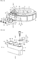
- Fig. 3 is a schematic perspective view of a power line, a stator, a motor coil, and a terminal mounting structure connecting a terminal of the motor coil to the power line that are taken out of a vehicle motor drive device.
- Fig. 4 is an exploded perspective view of the taken out terminal mounting structure shown in Fig. 3 .
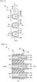
- Fig. 5 is an explanatory view of a taken out mounting stand as viewed from a side of the motor chamber L in a longitudinal direction of a conductive bar.
- Fig. 6 is a cross-sectional view of the mounting stand taken along line VI-VI of Fig. 5 , as viewed from an arrow direction.
- Figs. 3 to 6 show a terminal mounting structure according to a first embodiment.
- a receive-side terminal 19 is fixed to a distal end of each electrical lead 171 by caulking.
- the receive-side terminal 19 further extends from the distal end of the electrical lead 171, and includes a caulk part 19k that covers the distal end of the electrical lead 171 and a plate-like tongue piece 19t that extends from the caulk part 19k in an extending direction of the electrical lead 171.
- a through-hole 19h is formed in the tongue piece 19t (see Fig. 4 ).
- a direction of the through-hole 19h is perpendicular to an extending direction of the receive-side terminal 19.
- the mounting stand 42, the receive-side terminal 19, and a supply-side terminal 47 that constitute the terminal mounting structure are disposed on an outer diameter side of the stator 13 and the motor coil 17.
- the partition wall 41 is interposed between the mounting stand 42 and the stator 13.
- the mounting stand 42 includes a block-like base 43, three conductive bars 44, and three pairs of restricting members 46j, 46k.
- the base 43 that is a main body of the mounting stand 42 is formed in a substantially rectangular parallelepiped shape and is made of an insulating material, for example, a polymer material such as a heat-resistant resin.
- a step 43s, three through-holes 43h, and an ear-like fixing piece 43f are formed in the base 43.
- the step 43s is placed between an end part of the base 43 on a side of the inner space M and an end part of the base 43 on a side of the motor chamber L.
- the step 43s is a band-like flat surface extending around the base 43 and is oriented toward the side of the inner space M.
- the three through-holes 43h extend from the end part of the base 43 on the side of the inner space M to the end part of the base 43 on the side of the motor chamber L so as to be parallel to each other.
- the fixing piece 43f is disposed at the end part of the base 43 on the side of the motor chamber L.
- a fixing hole 43g that is parallel to the through-hole 43h is formed in the fixing piece 43f so as to pass through the fixing piece 43f.
- each conductive bar 44 is fitted into each through-hole 43h.
- An inner peripheral surface of the through-hole 43h contacts an outer peripheral surface of the conductive bar 44 without any gap and both end parts of the conductive bar 44 are exposed on both end surfaces of the base 43.
- Each conductive bar 44 is made of a conductive body such as copper, a copper alloy, and other metals, extends linearly, and has flat both end surfaces.
- a female screw hole 44h is formed in the end surface of the conductive bar 44 on the side of the motor chamber L.
- the female screw hole 44h extends to be parallel to a longitudinal direction of the conductive bar 44.
- an end part of the conductive bar 44 on the side of the motor chamber L is formed to be eccentric from a center axis of the conductive bar 44. An eccentric direction is directed to the motor coil 17.
- a cross-section of the conductive bar 44 at the end part on the side of the motor chamber L is not a circular cross-section with the female screw hole 44h being the center but a deformed cross-section in which with respect to the female screw hole 44h, a side near the motor coil 17 is large and a side far from the motor coil 17 is small.
- the plurality of conductive bars 44 are aligned on a reference line Q at intervals and extend in parallel to each other to be perpendicular to the reference line Q.
- the receive-side terminal 19 is fixed to the end part of each conductive bar 44 on the side of the motor chamber L. Specifically, as shown in Fig. 4 , the screw 48 passes through the through hole 19h of each receive-side terminal 19 and a distal end part of the screw 48 is screwed into the female screw hole 44h of the conductive bar 44. By rotating and tightening the screw 48, the screw 48 causes the tongue piece 19t to surface-contact an end surface of the conductive bar 44.
- the supply-side terminal 47 is mounted on and fixed to the end part of each conductive bar 44 on the side of the inner space M ( Fig. 2 ) by the screw 45 that is similar to the screw 48.
- the supply-side terminal 47 is fixed to a distal end of the core line 103 of each power line 101 by caulking.
- the conductive bar 44 is a supply-side component as viewed from the receive-side terminal 19.
- a pair of restricting members 46j, 46k is provided for each conductive bar 44 on the end part of the mounting stand 42 on the side of the motor chamber L.
- the restricting members 46j, 46k are disposed to be symmetrical to each other with respect to a center line R of the receive-side terminal 19 extending along an extending direction of the receive-side terminal 19 (see Fig. 5 ).
- the restricting member 46j is a wall that extends in an arc shape along one side of the tongue piece 19t
- the restricting member 46k is a wall that extends in an arc shape along the other side of the tongue piece 19t.
- the shape of the restricting member 46j on one side of the tongue piece 19t is the same as that of the restricting member 46k on the other side of the tongue piece 19t, and thus these restricting members 46j, 46k are simply referred to as the "restricting member 46" when the restricting member 46j on one side of the tongue piece 19t is not particularly distinguished from the restricting member 46k on the other side of the tongue piece 19t.
- the wall-like restricting member 46 extends from a base end side of the receive-side terminal 19 to a distal end side thereof across the reference line Q.
- the center line R is perpendicular to an axis of the female screw hole 44h.
- each restricting member 46j, 46k is integrally formed with the base 43 and restricting members 46j, 46k of each pair face an end part of each conductive bar 44 with a gap being interposed therebetween. Further, three pairs of restricting members 46j, 46k stand from the end surface of the base 43 and project over the end part of each conductive bar 44 toward the side of the motor chamber L. Accordingly, a projecting end of each restricting member 46 reaches the tongue piece 19t of the receive-side terminal 19, as shown in Fig. 3 . That is, the projecting end of the restricting member 46 projects further than the end surface of the conductive bar 44 which contacts the tongue piece 19t and to which the tongue piece 19t is fixed.
- the restricting member 46 functions as a contact prevention mechanism and prevents adjacent receive-side terminals 19, 19 from contacting with each other. Specifically, the receive-side terminal 19 is screwed between a pair of restricting members 46j, 46k, and even if the screw 48 becomes loose and the receive-side terminal 19 rotates about the screw 48, the rotation range of the receive-side terminal 19 is restricted by this pair of restricting members 46j, 46k. Accordingly, there is no possibility that adjacent receive-side terminals 19, 19 contact with each other and a short-circuit occurs between the receive-side terminals 19, 19.
- each restricting member 46 is disposed at an end part of each of three conductive bars 44. Therefore, even if any of three screws 48 becomes loose, it is possible to prevent a short-circuit of adjacent receive-side terminals 19, 19.
- a pair of restricting members 46j, 46k is provided only at a center conductive bar 44 of the three conductive bars 44, it is possible to prevent a short-circuit of adjacent receive-side terminals 19, 19. This is because the restricting member 46 is placed between the adjacent receive-side terminals 19, 19.
- Fig. 7 is a schematic perspective view of a power line, a stator, a motor coil, and a terminal mounting structure according to the second embodiment that are taken out of a vehicle motor drive device.
- Fig. 8 is an exploded perspective view of the taken out terminal mounting structure shown in Fig. 7 .
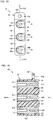
- Fig. 9 is an explanatory view of a taken out mounting stand as viewed from a side of a motor chamber L in a longitudinal direction of a conductive bar.
- Fig. 10 is a cross-sectional view of the mounting stand taken along line X-X of Fig. 9 , as viewed from an arrow direction.
- the structure that is common to that of the embodiment described above is denoted by the same reference numeral and the description thereof is omitted. Only a structure that is different from that of the embodiment described above is described below.
- a pair of restricting members 50j, 50k is integrally formed with an end part of each conductive bar 44 according to the second embodiment.
- the restricting members 50j, 50k are disposed on one side and the other side so as to be symmetrical to each other with respect to a center line R and project from an end surface of the conductive bar 44 on the side of the motor chamber L to the side of the motor chamber L so as to reach a receive-side terminal 19. That is, projecting ends of the restricting members 50j, 50k project further than the end surface of the conductive bar 44 which contacts a tongue piece 19t of the receive-side terminal 19 and to which the tongue piece 19t is fixed.
- the restricting member 50j extends along one side of the receive-side terminal 19 like a wall, and the restricting member 50k extends along the other side of the receive-side terminal 19 like a wall.
- the wall-like restricting members 50j, 50k are disposed on a base end side of the receive-side terminal 19 and do not extend across a reference line Q.
- the restricting members 50j, 50k function as a contact prevention mechanism and prevent adjacent receive-side terminals 19, 19 from contacting with each other. Specifically, each receive-side terminal 19 is screwed between a pair of 50j, 50k. The receive-side terminal 19 is thus positioned between a pair of restricting members 50j, 50k and does not rotate about a screw 48. Even if the screw 48 becomes loose, there is no possibility that adjacent receive-side terminals 19, 19 contact with each other and a short-circuit occurs between the receive-side terminals 19, 19.
- the restricting members 50j, 50k made of an insulating material may be mounted on and fixed to the end part of the conductive bar 44.
- Fig. 11 is an explanatory view of a taken out mounting stand according to the third embodiment as viewed from a side of a motor chamber L in a longitudinal direction of a conductive bar.
- Fig. 12 is a cross-sectional view of the mounting stand taken along line XII-XII of Fig. 11 , as viewed from an arrow direction.
- the structure that is common to those of the embodiments described above is denoted by the same reference numeral and the description thereof is omitted. Only a structure that is different from those of the embodiments described above is described below.
- a pair of restricting members 63j, 63k is provided.
- the restricting members 63j, 63k are pins with a circular cross-section, a base end side of each of the restricting members 63j, 63k is integrally formed with a base 43, and a distal end side projects from an end surface of the base 43 on the side of the motor chamber L over an end part of a conductive bar 44 to reach a receive-side terminal 19. That is, a projecting end of each of the restricting members 63j, 63k projects further than an end surface of the conductive bar 44 which contacts a tongue piece 19t of the receive-side terminal 19 and to which the tongue piece 19t is fixed.
- the restricting members 63j, 63k are disposed to be symmetrical to each other with respect to a center line R and are placed on both sides of the receive-side terminal 19.
- the pin-shaped restricting members 63j, 63k are disposed on a base end side of the receive-side terminal 19 as viewed from a female screw hole 44h.
- a pair of restricting members 63j, 63k functions as a contact prevention mechanism. Specifically, even if a screw 48 becomes loose and the receive-side terminal 19 rotates about the screw 48, the rotation range of the receive-side terminal 19 is restricted by a pair of restricting 63j, 63k. Accordingly there is no possibility that adjacent receive-side terminals 19, 19 contact with each other and a short-circuit occurs between the receive-side terminals 19, 19.
- the pin-shaped restricting members 63j, 63k are made of an insulating material that is similar to that of the base 43, as a modified example (not shown), the pin-shaped restricting members 63j, 63k may be integrally formed with the end part of the conductive bar 44. In this case, the restricting members 63j, 63k are made of a conductive material that is similar to that of the conductive bar 44.
- Fig. 13 is an explanatory view of a taken out mounting stand according to the fourth embodiment as viewed from a side of a motor chamber in a longitudinal direction of a conductive bar.
- Fig. 14 is a cross-sectional view of the mounting stand taken along line XIV-XIV of Fig. 13 , as viewed from an arrow direction.
- the structure that is common to those of the embodiments described above is denoted by the same reference numeral and the description thereof is omitted. Only a structure that is different from those of the embodiments described above is described below.
- a plurality of projecting parts 84 are provided on a base 43 of a mounting stand 42.
- Each projecting part 84 is made of an insulating material, a base end side of each projecting part 84 is integrally formed with an end surface of the base 43, and a distal end side projects over an end part of a conductive bar 44 to reach a receive-side terminal 19. That is, a projecting end of each projecting part 84 projects further than an end surface of the conductive bar 44 which contacts a tongue piece 19t of the receive-side terminal 19 and to which the tongue piece 19t is fixed.
- Each projecting part 84 is a wall that is disposed between adjacent receive-side terminals 19, 19 and extends across a reference line Q to be parallel to a center line R.
- a terminal mounting structure includes the projecting part 84.
- the base end side of the projecting part 84 is provided on the mounting stand 42 and the distal end side of the projecting part 84 projects over the end part of the conductive bar 44 to be placed between adjacent receive-side terminals 19, 19.
- the projecting part 84 functioning as a contact prevention mechanism prevents the adjacent receive-side terminals 19, 19 from contacting with each other. Even if a screw 48 becomes loose and the receive-side terminal 19 rotates about the screw 48, the receive-side terminal 19 only abuts against the projecting part 84 and does not rotate over the projecting part 84. As a result, there is no possibility that the adjacent receive-side terminals 19, 19 contact with each other and a short-circuit occurs between the receive-side terminals 19, 19.
- Fig. 15 is an explanatory view of a taken out mounting stand according to the fifth embodiment as viewed from a side of a motor chamber in a longitudinal direction of a conductive bar.
- Fig. 16 is a cross-sectional view of the mounting stand taken along line XVI-XVI of Fig. 15 , as viewed from an arrow direction.
- the structure that is common to those of the embodiments described above is denoted by the same reference numeral and the description thereof is omitted. Only a structure that is different from those of the embodiments described above is described below.
- recessed parts 85 that receive receive-side terminals 19, respectively are formed in a base 43 according to the fifth embodiment.
- the recessed parts 85 are placed on an end surface of the base 43 on a side of a motor chamber L and disposed to be spaced apart from each other along a reference line Q.
- each recessed part 85 is a cutout that extends from an edge part 81 on a side near a motor coil 17 along a center line R, and an edge part 82 on a side far from the motor coil 17 is not cut out and thus a projecting part 83 remains.
- the projecting part 83 has a comb-like shape as viewed from the side of the motor chamber L ( Fig.
- a tip of a comb tooth of the projecting part 83 extends from the edge part 82 of the base 43 over the reference line Q to the edge part 81 of the base 43.
- the projecting part 83 is formed to rise more than an end surface of a conductive bar 44 which contacts a tongue piece 19t of a receive-side terminal 19 and to which the tongue piece 19t is fixed.
- a terminal mounting structure includes the projecting part 83.
- the projecting part 83 is a part of the base 43 that partitions adjacent recessed parts 85, 85 and is placed between adjacent receive-side terminals 19, 19.
- the projecting part 83 functioning as a contact prevention mechanism prevents the adjacent receive-side terminals 19, 19 from contacting with each other. Even if a screw 48 becomes loose and the receive-side terminal 19 rotates about the screw 48, the receive-side terminal 19 only abuts against the projecting part 83 and does not rotate over the projecting part 83. As a result, there is no possibility that the adjacent receive-side terminals 19, 19 contact with each other and a short-circuit occurs between the receive-side terminals 19, 19.
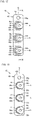
- FIG. 17 is an explanatory view of a taken out mounting stand according to the sixth embodiment as viewed from a side of a motor chamber in a longitudinal direction of a conductive bar.
- the sixth embodiment is a modification of the first embodiment.
- a terminal mounting structure according to the sixth embodiment includes a wall-like restricting member 86.
- a base end side of the restricting member 86 is integrally formed with a base 43, a distal end side of the restricting member 86 projects from an end surface of the base 43 on a side of a motor chamber L over an end part of a conductive bar 44 to reach a receive-side terminal 19. That is, a projecting end of the restricting member 86 projects further than an end surface of the conductive bar 44 which contacts a tongue piece 19t of the receive-side terminal 19 and to which the tongue piece 19t is fixed.
- the restricting member 86 is a C-shaped wall that extends from one side part 86j of the restricting member 86 to the other side part 86k of the restricting member 86 so as to surround the receive-side terminal 19.
- the one side part 86j of the restricting member 86 extends along one side of the receive-side terminal 19 like the restricting member 46j ( Fig. 5 ) described above
- the other side part 86k of the restricting member 86 extends along the other side of the receive-side terminal 19 like the restricting member 46k ( Fig. 5 ) described above
- the one side part 86j and the other side part 86k extend along a distal end edge of the receive-side terminal 19 to be connected to each other.
- the restricting member 86 is formed.
- the restricting member 86 functions as a contact prevention mechanism and thus prevents adjacent receive-side terminals 19, 19 from contacting with each other.
- the receive-side terminal 19 is positioned between the one side part 86j and the other side part 86k so as not to be rotatable. Accordingly, even if a screw 48 becomes loose and the receive-side terminal 19 rotates about the screw 48, the rotation range of the receive-side terminal 19 is restricted by the one side part 86j and the other side part 86k. As a result, there is no possibility that the adjacent receive-side terminals 19, 19 contact with each other and a short-circuit occurs between the receive-side terminals 19, 19.
- FIG. 18 is an explanatory view of a taken out mounting stand according to the seventh embodiment as viewed from a side of a motor chamber in a longitudinal direction of a conductive bar.
- a terminal mounting structure according to the seventh embodiment is a modification of the second embodiment and a wall-like restricting member 50u is integrally formed along an outer periphery of an end part of a conductive bar 44.
- the restricting member 50u projects from an end surface of the conductive bar 44 on a side of a motor chamber L to reach a receive-side terminal 19. That is, a projecting edge of the restricting member 50u projects further than the end surface of the conductive bar 44 which contacts a tongue piece 19t of the receive-side terminal 19 and to which the tongue piece 19t is fixed.
- the restricting member 50u extends in a U-shape from one side part 50j of the restricting member 50u to the other side part 50k of the restricting member 50u so as to surround the receive-side terminal 19.
- the one side part 50j of the restricting member 50u extends along one side of the receive-side terminal 19 like the restricting member 50j ( Fig. 9 ) described above
- the other side part 50k of the restricting member 50u extends along the other side of the receive-side terminal 19 like the restricting member 50k ( Fig. 9 ) described above
- the one side part 50j and the other side part 50k extend along a distal end edge of the receive-side terminal 19 to be connected to each other. That is to say, when the restricting members 50j, 50k according to the second embodiment are extended to be connected to each other, the restricting member 50u is formed.
- the restricting member 50u functions as a contact prevention mechanism and thus prevents adjacent receive-side terminals 19, 19 from contacting with each other.
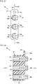
- the receive-side terminal 19 is positioned between the one side part 50j and the other side part 50k so as not to be rotatable. Accordingly, even if a screw 48 becomes loose, the receive-side terminal 19 does not rotate about the screw 48 and there is no possibility that the adjacent receive-side terminals 19, 19 contact with each other and a short-circuit occurs between the receive-side terminals 19, 19.
- Fig. 19 is a schematic perspective view of a power line, a stator, a motor coil, and a terminal mounting structure according to the comparative example that are taken out of a vehicle motor drive device.
- Fig. 20 is an exploded perspective view of the taken out terminal mounting structure shown in Fig. 19 .
- Fig. 21 is an explanatory view of a taken out mounting stand as viewed from a side of a motor chamber in a longitudinal direction of a conductive bar.
- Fig. 22 is a cross-sectional view of the mounting stand taken along line XXII-XXII of Fig. 21 , as viewed from an arrow direction.
- Amounting stand 42 according to the comparative example does not include a pair of restricting members 46j, 46k according to the first embodiment ( Figs. 3 to 6 ), a pair of restricting members 50j, 50k according to the second embodiment ( Figs. 7 to 10 ), a pair of restricting members 63j, 63k according to the third embodiment ( Figs. 11, 12 ), the projecting part 84 according to the fourth embodiment ( Figs. 13, 14 ), the projecting part 83 according to the fifth embodiment ( Figs. 15, 16 ), the C-shaped restricting member 86 according to the sixth embodiment ( Fig. 17 ), and the U-shaped restricting member 50u according to the seventh embodiment ( Fig. 18 ).
- a receive-side terminal 19 is not restricted or positioned. Accordingly, if a screw 48 becomes loose, the receive-side terminal 19 rotates about the screw 48, and there is a possibility that adjacent receive-side terminals 19, 19 contact with each other and a short-circuit occurs between the receive-side terminals 19, 19.
- the inventors have found that a short-circuit may occur in the comparative example and thus have developed the present invention in order to solve the problem.
- the terminal mounting structure according to the present invention is advantageously used in an electric car and a hybrid vehicle.
Landscapes
- Engineering & Computer Science (AREA)
- Power Engineering (AREA)
- Life Sciences & Earth Sciences (AREA)
- Sustainable Development (AREA)
- Sustainable Energy (AREA)
- Transportation (AREA)
- Mechanical Engineering (AREA)
- Motor Or Generator Frames (AREA)
Abstract
Description
- The present invention relates to a vehicle motor drive device that drives a wheel of an electric car, a hybrid car, and the like and in particular to a structure for mounting a terminal of a motor coil on a conductive bar on a power supply side in the vehicle motor drive device.
- For example, the vehicle motor drive device described in
Japanese Unexamined Patent Application Publication No. 2010-172069 - In the vehicle motor drive device described in Patent Literature 1, electrical wiring within the vehicle motor drive device is unclear. Particularly, the electrical wiring from a distal end of a power cable drawn from outside into the vehicle motor drive device to a stator coil of a motor portion of the vehicle motor drive device is unclear.
- The inner space of the vehicle motor drive device is cut off from outside of the vehicle motor drive device so that foreign matters do not enter the vehicle motor drive device from the outside. It is conceivable that a terminal structure is provided on a casing of the vehicle motor drive device that functions as a partition between the inner space of the vehicle motor drive device and the outside, a distal end of the power cable placed in the outside is connected to the terminal structure, and a terminal of the stator coil placed in the inner space is also connected to the terminal structure, so that the power cable is connected via the terminal structure to the stator coil.
- PTL 1:
Japanese Unexamined Patent Application Publication No. 2010-172069 - The present inventors have found that there are problems in the terminal structure described above, as bescribed below. A vehicle motor drive device includes a large number of rotating components such as a shaft and a gear and these rotating components rotate at various rotation speeds, and thus the vehicle motor drive device vibrates during a drive operation. Particularly, an in-wheel motor drive device is mounted on a vehicle body via a suspension device, and thus the in-wheel motor drive device bounces and rebounds and repeatedly receives lateral force from tires of wheels at the time of turning, acceleration force at the time of start, and speed reduction force at the time of braking. When various vibrations and force act on the terminal structure for a long period of time, screws used in the terminal structure become loose and terminals may rotate about these loose screws. When two or more terminals are arranged side by side, a short-circuit of the terminals may occur because of the rotation of the terminals.
- Further, it is difficult to visually check the inside of the vehicle motor drive device in daily inspection and maintenance. Even if a screw becomes loose, it is desirable to prevent a short-circuit of terminals.
- In view of the above problems, an object of the invention is to prevent a short-circuit of terminals of a motor coil disposed in a vehicle motor drive device.
- To achieve the object, a terminal mounting structure for a vehicle motor drive device according to the present invention includes a plurality of electrical leads that extend from a motor coil of the vehicle motor drive device, a plurality of receive-side terminals each of which extends from a distal end of each of the electrical leads, a mounting stand that includes an electrically-insulating base and a plurality of supply-side conductive bars that are disposed at intervals and extend so as to pass through the base, a plurality of screws each of which passes through the receive-side terminal in a direction crossing an extending direction of the receive-side terminal, each of which is screwed into a screw hole formed at an end part of the supply-side conductive bar so as to cause each of the receive-side terminals to contact each of the supply-side conductive bars and to fix each of the receive-side terminals to each of the supply-side conductive bars, and a contact prevention mechanism that is provided in the mounting stand so as to prevent adjacent receive-side terminals from contacting with each other.
- According to the present invention, even if a screw becomes loose and a receive-side terminal extending from the distal end of an electrical lead rotates about the screw, the receive-side terminal only abuts against a contact prevention mechanism that is placed between adjacent receive-side terminals and thus it is possible to prevent the adjacent receive-side terminals from abutting against each other and a short-circuit from occurring between the receive-side terminals. For example, as a structure for enabling the screw to pass through the receive-side terminal, the receive-side terminal includes a hole that passes through the receive-side terminal in a direction crossing the extending direction of the receive-side terminal. Alternatively, the receive-side terminal is a plate piece, a cutout is formed in a part of the plate piece and thus the remaining part of the plate piece has a square U-shape, so that the screw passes the plate piece through the cutout in a thickness direction of the plate piece.
- The structure of the contact prevention mechanism is not particularly limited. For example, the contact prevention mechanism is a cover that covers each receive-side terminal. According to an embodiment of the present invention, the contact prevention mechanism includes a restricting member that restricts a rotation of the receive-side terminal about the screw within a predetermined range. According to such an embodiment, even if any of a plurality of adjacent receive-side terminals rotates, the rotation range of the receive-side terminal is restricted and thus it is possible to prevent a short-circuit of the receive-side terminals.
- The structure of the restricting member is not particularly limited. According to a preferable embodiment, the restricting member is a projection whose base end side is provided on an end part of the supply-side conductive bar or on the base and whose distal end side projects from the end part of the supply-side conductive bar so as to reach the receive-side terminal, the restricting member is disposed on one side and the other side of each receive-side terminal so as to be symmetrical to each other with respect to a center line of the receive-side terminal that extends in an extending direction of the receive-side terminal, and the restricting member restricts the rotation range of the receive-side terminal between a restricting member on one side and a restricting member on the other side.
- The restricting member may be formed separately from the base, or may be integrally formed with the base. The restricting member provided at the end part of the supply-side conductive bar may be integrally formed with the supply-side conductive bar, or the separately formed restricting member may be mounted on the end part of the supply-side conductive bar. When the base end side of the restricting member is integrally formed with an outer periphery of the end part of the supply-side conductive bar, the restricting member on one side and the restricting member on the other side can be securely fixed to the supply-side conductive bar. Further, the restricting member can be made of a conductive material that is similar to that of the supply-side conductive bar. According to another embodiment of the present invention, the base end side of the restricting member may be embedded in a boundary of the supply-side conductive bar and the base and fixed to the boundary. According to yet another embodiment of the present invention, the base end side of the restricting member may be fitted into the end part of the supply-side conductive bar and fixed to the end part by a sleeve and the like.
- The shape of the restricting member disposed on one side and the other side of each receive-side terminal is not particularly limited. According to an embodiment of the present invention, the restricting member on one side and the restricting member on the other side are a pair of walls extending along one side edge and the other side edge of the receive-side terminal, respectively. According to such an embodiment, the restricting member is a wall extending along a side edge of the receive-side terminal, and thus even if the receive-side terminal rotates, the wall-like restricting member is always interposed between a plurality of adjacent receive-side terminals and a short-circuit can thus be prevented. According to another embodiment of the present invention, the restricting member is not a wall but a pin and the like further extending from the end part of the supply-side conductive bar.
- The paired walls functioning as a restricting member do not need to be connected to each other. Alternatively, the restricting member on one side and the restricting member on the other side may extend along a distal end edge of the receive-side terminal so as to be connected to each other. According to such an embodiment, a wall-like restricting member extends in a C-shape or a U-shape so as to surround an outer edge of each receive-side terminal. Accordingly, it is possible to reliably prevent a rotation and a short-circuit of each receive-side terminal.
- While the restricting member is placed between a plurality of adjacent receive-side terminals in the embodiment in which a pair of restricting members constituted by a restricting member on one side and a restricting member on the other side is provided as described above, the present invention is not limited to the embodiment. It suffices that the contact prevention mechanism is a member that is disposed between the adjacent receive-side terminals and it is not necessary to provide the contact prevention mechanism in pairs. According to an embodiment of the present invention, the contact prevention mechanism is a wall that stands on a base surface of the base and extends so as to cross a reference line that connects adjacent receive-side terminals. According to such an embodiment, even if a screw becomes loose and a receive-side terminal that extends from a distal end of an electrical lead rotates about the screw, the receive-side terminal only abuts against the wall placed between the adjacent receive-side terminals and it is possible to prevent the adjacent receive-side terminals from abutting against each other and a short-circuit from occurring between the receive-side terminals. For example, the wall extends to be parallel to the extending direction of the receive-side terminal.
- According to another embodiment of the present invention, a plurality of recessed parts that receive the respective receive-side terminals are formed in the base and the contact prevention mechanism is a part of the base that partitions adjacent recessed parts. According to such an embodiment, even if a screw becomes loose, it is possible to restrict a rotation of a receive-side terminal about the screw by a part of the base that partitions adjacent recessed parts.
- As described above, according to the present invention, even if a screw becomes loose and thus a supply-side conductive bar does not contact a receive-side terminal and is not fixed to the receive-side terminal, it is possible to prevent a short-circuit of adjacent receive-side terminals. Accordingly, even if a vibrating vehicle motor drive device is operated for a long period of time, a short-circuit of electrical leads of a motor coil does not occur in the vehicle motor drive device.
-
- [
Fig. 1] Fig. 1 is a rear view of a vehicle motor drive device. - [
Fig. 2] Fig. 2 is a longitudinal sectional view of the vehicle motor drive device taken along line II-II ofFig. 1 , as viewed from an arrow direction. - [
Fig. 3] Fig. 3 is a perspective view of a motor coil and a terminal mounting structure according to a first embodiment that are taken out of the vehicle motor drive device. - [
Fig. 4] Fig. 4 is an exploded perspective view of the taken out terminal mounting structure according to the first embodiment. - [
Fig. 5] Fig. 5 is an explanatory view of a taken out mounting stand according to the first embodiment. - [
Fig. 6] Fig. 6 is a cross-sectional view of the mounting stand taken along line of VI-VI ofFig. 5 , as viewed from an arrow direction. - [
Fig. 7] Fig. 7 is a perspective view of a taken out motor coil and a taken out terminal mounting structure according to a second embodiment. - [
Fig. 8] Fig. 8 is an exploded perspective view of a taken out mounting stand according to the second embodiment. - [
Fig. 9] Fig. 9 is an explanatory view of the taken out mounting stand according to the second embodiment. - [
Fig. 10] Fig. 10 is a cross-sectional view of the mounting stand taken along line X-X ofFig. 9 , as viewed from an arrow direction. - [
Fig. 11] Fig. 11 is an explanatory view of a taken out mounting stand according to a third embodiment. - [
Fig. 12] Fig. 12 is a cross-sectional view of the mounting stand taken along line of XII-XII ofFig. 11 , as viewed from an arrow direction. - [
Fig. 13] Fig. 13 is an explanatory view of a taken out mounting stand according to a fourth embodiment. - [
Fig. 14] Fig. 14 is a cross-sectional view of the mounting stand taken along line of XIV-XIV ofFig. 13 , as viewed from an arrow direction. - [
Fig. 15] Fig. 15 is an explanatory view of a taken out mounting stand according to a fifth embodiment. - [
Fig. 16] Fig. 16 is a cross-sectional view of the mounting stand taken along line of XVI-XVI ofFig. 15 , as viewed from an arrow direction. - [
Fig. 17] Fig. 17 is an explanatory view of a taken out mounting stand according to a sixth embodiment. - [
Fig. 18] Fig. 18 is an explanatory view of a taken out mounting stand according to a seventh embodiment. - [
Fig. 19] Fig. 19 is a perspective view of a taken out motor coil and a taken out terminal mounting structure according to a comparative example. - [
Fig. 20] Fig. 20 is an exploded perspective view of a taken out mounting stand according to the comparative example. - [
Fig. 21] Fig. 21 is an explanatory view of the taken out mounting stand according to the comparative example. - [
Fig. 22] Fig. 22 is a cross-sectional view of the mounting stand according to the comparative example taken along line XXII-XXII ofFig. 21 , as viewed from an arrow direction. - Embodiments of the present invention are described in detail below with reference to the drawings.
Fig. 1 is a rear view of a vehicle motor drive device including a terminal mounting structure according to the present invention, as viewed from a vehicle-width direction inner side of an electric car (an inboard side).Fig. 2 is a longitudinal sectional view of the vehicle motor drive device taken along line II-II ofFig. 1 , as viewed from an arrow direction. The vehicle motor drive device is described first. An in-wheelmotor drive device 11 shown inFigs. 1 and2 is a vehicle motor drive device that is provided within a wheel of an electric car or a hybrid vehicle, and is mounted via a suspension device (not shown) on a vehicle body. - As shown in
Fig. 1 , the in-wheelmotor drive device 11 has a substantially cylindrical shape and includes amotor portion 11A, aspeed reduction portion 11B, and a wheel hub bearing portion 11C that are sequentially and coaxially disposed in series in a direction of an axis O of the in-wheelmotor drive device 11, as shown inFig. 2 . The wheel hub bearing portion 11C is disposed on a vehicle-width direction outer side of the electric car (an outboard side). Thespeed reduction portion 11B that is adjacent to the wheel hub bearing portion 11C has a larger diameter than that of the wheel hub bearing portion 11C. Themotor portion 11A that is adjacent to thespeed reduction portion 11B has a larger diameter than that of thespeed reduction portion 11B, and is disposed on a vehicle-width direction center side of the electric car (the inboard side). Alubricant oil tank 53 is additionally disposed under thespeed reduction portion 11B. Thelubricant oil tank 53 projects toward an outer diameter side further than themotor portion 11A. - A
casing 21a that forms the outer shape of themotor portion 11A has a substantially cylindrical shape as viewed from an axial direction of the in-wheelmotor drive device 11, and is a fixed member that is non-rotatable about the axil O of the in-wheelmotor drive device 11. Acasing 21b that forms the outer shape of thespeed reduction portion 11B is identical to thecasing 21a. On the other hand, the wheel hub bearing portion 11C includes a rotating member (a hub ring 77) on an inner ring side and a fixed member on an outer ring side (an outer ring member 80). A wheel (not shown) is mounted on and fixed to the rotating member (the hub ring 77), so that rotational driving force of themotor portion 11A and vehicle weight are transmitted to the wheel. At this time, while the wheel hub bearing portion 11C and thespeed reduction portion 11B are placed in an inner space area of the wheel, themotor portion 11A projects from the inner space area of the wheel toward the inboard side. Aterminal box 22 that projects toward an outer diameter side of a front of the vehicle is formed on thecasing 21a of themotor portion 11A (seeFig. 1 ). - As shown in
Fig. 2 , themotor portion 11A accommodates arotor 12, astator 13, and amotor shaft 14a of a rotating electric machine in a motor chamber L of thecasing 21a. An axial direction end of the substantially cylindrical-shapedcasing 21a is closed by a disc-shaped motorrear cover 21r. Thestator 13 is mounted on and fixed to an inner peripheral surface of thecasing 21a. Therotor 12 is disposed to be further toward an inner diameter side than thestator 13. Therotor 12 is mounted on and fixed to themotor shaft 14a extending along the axis O. Amotor coil 17 of thestator 13 is electrically connected to threepower lines 101. As alternating current is supplied from thepower line 101 to themotor coil 17, thestator 13 of themotor portion 11A generates electromagnetic force to rotate therotor 12 constituted by a permanent magnet or a magnetic body. Each of thepower lines 101 extends from an inverter (not shown) and is coated with an insulating material. One end of themotor shaft 14a is supported by the motorrear cover 21r via a rollingbearing 16. The other end of themotor shaft 14a is supported by apartition wall 21e via the rollingbearing 16. - The substantially cylindrical-shaped
casing 21b defines a speed reduction chamber N and accommodates a speed reduction mechanism for thespeed reduction portion 11B in the speed reduction chamber N. This speed reduction mechanism is a cycloidal reduction mechanism and includes aninput shaft 14b, a pair of twoeccentric members 71, two rollingbearings 72, twocurve boards 73 whose outer peripheral part is formed in a wave shape, a plurality ofinner pins 74, a plurality ofouter pins 75, and anoutput shaft 76. Theinput shaft 14b of thespeed reduction portion 11B is coupled and fixed to themotor shaft 14a of themotor portion 11A by spline fitting. Theinput shaft 14b and themotor shaft 14a extend along the axis O and integrally rotate, and thus are also referred to as a "motor-side rotating member". Theeccentric members 71 are respectively provided on theinput shaft 14b to be eccentric from the axis O at phases that are different from each other by 180°. Each of the twocurve boards 73 has a center hole and an inner peripheral surface of this center hole is rotatably supported by an outer peripheral surface of eacheccentric member 71 via each rollingbearing 72. Each of theouter pins 75 is fixed to anouter pin housing 79 that is elastically supported by thecasing 21b to engage with the wavy-shaped outer peripheral part of thecurve board 73, so that thecurve board 73 revolving about the axis O at a high speed is slightly rotated. The inner pins 74 are mounted on and fixed to theoutput shaft 76 to pass through a plurality of through-holes 73h that are formed in thecurve board 73 at predetermined intervals in a peripheral direction, in order to obtain only the rotation of thecurve boards 73 and transmit the rotation to theoutput shaft 76. The rotational speed of theinput shaft 14b is thus reduced by thespeed reduction portion 11B and then the rotation is output from theoutput shaft 76. Thespeed reduction portion 11B functioning as a cycloidal reduction mechanism has a higher reduction rate than that of a speed reduction mechanism constituted by a planetary gear set or a parallel shaft gear set, and thus contributes to downsizing and weight reduction of the in-wheelmotor drive device 11. - The
hub ring 77 of the wheel hub bearing portion 11C is coupled and fixed to theoutput shaft 76. Thehub ring 77 is rotatably supported by theouter ring member 80 via the rollingbearing 78. A road wheel of a wheel (not shown) is mounted on and fixed to thehub ring 77 via abolt 69. The rollingbearing 78 has two rows, and for example, is a multiple-row angular ball bearing. - An operation principle of the in-wheel
motor drive device 11 with the structure described above is schematically described. When electricity is applied to themotor portion 11A and power is supplied to themotor coil 17 of thestator 13, therotor 12 rotates and the rotation is output from themotor shaft 14a to theinput shaft 14b of thespeed reduction portion 11B. Thespeed reduction portion 11B reduces a high speed rotation of theinput shaft 14b and outputs a low speed rotation from theoutput shaft 76 to thehub ring 77 of the wheel hub bearing portion 11C. Thespeed reduction portion 11B has a cycloidal reduction mechanism, and thus as compared to a speed reduction mechanism constituted by a parallel shaft gear or by a planetary gear set, thespeed reduction portion 11B is downsized, has a higher reduction ratio, and the weight thereof is reduced. Accordingly, a reduction ratio obtained by dividing the rotation number of theoutput shaft 76 by the rotation number of theinput shaft 14b is in the range of 1/10 to 1/15. - A lubrication mechanism of the in-wheel
motor drive device 11 is further described. The in-wheelmotor drive device 11 includes a lubricant oil circuit with a shaft-center oil supply system and lubricates themotor portion 11A and thespeed reduction portion 11B. Specifically, alubricant oil pump 51 is provided on thepartition wall 21e of the casing that functions as a boundary of the motor chamber L that accommodates therein themotor portion 11A and the speed reduction chamber N that accommodates therein thespeed reduction portion 11B. Thelubricant oil pump 51 is disposed coaxially with the axis O and is driven by an innerpin reinforcing member 74b fixed to theinner pin 74. That is, thelubricant oil pump 51 is driven by an output rotation of thespeed reduction portion 11B. Asuction oil path 52 that is formed in thepartition wall 21e extends vertically, an upper end of thesuction oil path 52 is connected to a suction port of thelubricant oil pump 51, and a lower end of thesuction oil path 52 is connected to thelubricant oil tank 53 that is provided under thespeed reduction portion 11B. An ejection oil path (not shown) that is formed in the wall thickness of thepartition wall 21e and the wall thickness of thecasing 21a extends from an ejection port of thelubricant oil pump 51 to the motorrear cover 21r. - Among both ends of the ejection oil path (not shown), an end on a side of the motor
rear cover 21r is connected to an outer diameter side end of a communication oil path 56 (only an inner diameter side end is shown inFig. 2 ) that is formed in the wall thickness of the motorrear cover 21r. Thecommunication oil path 56 extends between an inner wall surface and an outer wall surface of the motorrear cover 21r that becomes a disc-shaped wall in a radial direction. The inner diameter side end of thecommunication oil path 56 is connected to a motorshaft oil path 58a that is provided in themotor shaft 14a as shown inFig. 2 . - The motor
shaft oil path 58a is provided inside of themotor shaft 14a and extends along the axis O. One end of the motorshaft oil path 58a near thespeed reduction portion 11B is connected to a speed-reduction-portion inputshaft oil path 58b that is provided in theinput shaft 14b and extends along the axis O. The other end of the motorshaft oil path 58a far from thespeed reduction portion 11B (the end on a side of the motorrear cover 21r) is connected to thecommunication oil path 56 described above. Further, the motorshaft oil path 58a is also connected to an inner diameter side end of arotor oil path 64 that is formed in a rotor flange part of an axial direction center part. - The speed-reduction-portion input
shaft oil path 58b is provided inside of theinput shaft 14b and extends between both ends of theinput shaft 14b along the axis O. Alubricant oil hole 60 is provided at one end of the speed-reduction-portion inputshaft oil path 58b that is opposite to theoutput shaft 76. Thelubricant oil hole 60 communicates with the speed reduction chamber N. - The speed-reduction-portion input
shaft oil path 58b branches to alubricant oil path 59 that extends radially outward in eacheccentric member 71. An outer diameter side end of thelubricant oil path 59 is connected to the rollingbearing 72 that is provided between an outer peripheral surface of theeccentric member 71 and an inner peripheral surface of thecurve board 73. - A speed-reduction-
portion return hole 61 is provided at the bottom of the speed reduction chamber N. The speed-reduction-portion return hole 61 passes through the substantially cylindrical-shapedcasing 21b in a radial direction to cause the speed reduction chamber N to communicate with thelubricant oil tank 53. A motor-portion return hole 66 is provided at the bottom of the motor chamber L. The motor-portion return hole 66 passes through thepartition wall 21e in a direction of the axis O to cause the motor chamber L to communicate with thelubricant oil tank 53. - An operation of the lubricant oil circuit is described. The
lubricant oil pump 51 driven by theoutput shaft 76 via the innerpin reinforcing member 74b sucks lubricant oil stored in thelubricant oil tank 53 through thesuction oil path 52 as indicated by a white blank arrow inFig. 2 and ejects the lubricant oil to an ejection oil path (not shown). The lubricant oil is pressurized by thelubricant oil pump 51 and sequentially flows in the ejection oil path (not shown), thecommunication oil path 56, and the motorshaft oil path 58a. A part of the lubricant oil flowing in the motorshaft oil path 58a flows in therotor oil path 64 and is injected from an outer peripheral surface of therotor 12 to the motor chamber L. The lubricant oil then flows toward the bottom of the motor chamber L by gravity, passes through the motorportion return hole 66, and returns to thelubricant oil tank 53. In this way, themotor portion 11A is cooled and lubricated by the shaft-center oil supply system. The motor chamber L is filled with droplets of the injected lubricant oil and thus in an oil atmosphere. - The lubricant oil flowing from the motor
shaft oil path 58a into the speed-reduction-portion inputshaft oil path 58b branches to flow in thelubricant oil path 59 and thelubricant oil hole 60 and then to be injected to the speed reduction chamber N. As a result, the lubricant oil is adhered to theeccentric member 71, the rollingbearing 72, thecurve board 73, theinner pin 74, and theouter pin 75 of thespeed reduction portion 11B. Next, the lubricant oil flows toward the bottom of the speed reduction chamber N by gravity, passes through the speed-reduction-portion return hole 61, and returns to thelubricant oil tank 53. In this way, thespeed reduction portion 11B is cooled and lubricated by the shaft-center oil supply system. The speed reduction chamber N is filled with droplets of the injected lubricant oil and thus in an oil atmosphere. - As shown in
Fig. 1 , theterminal box 22 is formed on an outer periphery of thecasing 21a of themotor portion 11A. Theterminal box 22 projects toward a front of the vehicle and includes acover plate 105 that closes a distal end opening of theterminal box 22. Four through-holes are formed in thecover plate 105, and threepower lines 101 and asignal line 102 are drawn through these through holes into the in-wheelmotor drive device 11. As shown inFig. 2 , eachpower line 101 is a flexible electrical cable that includes aconductive core line 103 and an insulating outer cover that covers thecore line 103. A U phase, a V phase, and a W phase of three-phase alternating current flow in thepower lines 101, respectively. A distal end part of eachpower line 101 passes through asleeve 107. Eachsleeve 107 connects the outer cover of thepower line 101 to thecover plate 105 under a sealed state. For this reason, eachcore line 103 that passes through thecover plate 105 to be drawn into theterminal box 22 is cut off from outside of the in-wheelmotor drive device 11. - The
signal line 102 is a cable obtained by bundling a plurality of core lines having insulating coating separately applied thereto into one line. Thesignal line 102 is connected via theterminal box 22 to a plurality of sensors installed in the in-wheelmotor drive device 11. For example, the plurality of sensors may be arotation number sensor 18 and a temperature sensor (not shown). - As shown in
Fig. 2 , theterminal box 22 is disposed to be close to the motorrear cover 21r of thecasing 21a and thus interference of theterminal box 22 with a wheel (not shown) is prevented. A casing of theterminal box 22 is formed in a substantially rectangular parallelepiped box shape. The casing is divided into afirst casing 22a and asecond casing 22r, and thefirst casing 22a is tightly joined to thesecond casing 22r. Thefirst casing 22a is integrally formed with thecasing 21a. Thesecond casing 22r is integrally formed with the motorrear cover 21r. - As shown in
Fig. 1 , theterminal box 22 projects toward a front of the vehicle. As shown inFig. 2 , anopening 23 that communicates with the outside of the in-wheelmotor drive device 11 is provided on a projecting end side of theterminal box 22. Apartition wall 41 between an inner space M of theterminal box 22 and the motor chamber L is provided on a base end side of theterminal box 22. Thepartition wall 41 is integrally formed with thecasing 21a and is a cylindrical part that has the same diameter as that of thecasing 21a. Thepartition wall 41 is made of a light alloy such as aluminum, similarly to thefirst casing 22a and thecasing 21a. - As shown in
Fig. 2 , an outer peripheral surface of thepartition wall 41 faces an inner wall surface of thefirst casing 22a, and apath 24 is defined between thepartition wall 41 and thefirst casing 22a. One end of thepath 24 extending in parallel to the axis O communicates with the motor chamber L and the other end of thepath 24 communicates with the inner space M of theterminal box 22. The one end of thepath 24 is sealed by thesecond casing 22r. The other end of thepath 24 is sealed by acover 49. Thecover 49 is removably mounted on and fixed to thefirst casing 22a. - A mounting
stand 42 for a terminal mounting structure is provided in the middle of thepath 24. The mountingstand 42 blocks thepath 24 in the middle thereof. Accordingly, one end of the mountingstand 42 faces the motor chamber L and the other end of the mountingstand 42 faces the inner space M. The motor chamber L does not communicate with the inner space M.The mounting stand 42 includes ascrew 48 that is screwed into the one end of the mountingstand 42 on a side of the motor chamber L and ascrew 45 that is screwed into the other end of the mountingstand 42 on a side of the inner space M. A head part of thescrew 48 faces thesecond casing 22r, and thus it is possible to prevent thescrew 48 from coming off of the mountingstand 42. A head part of thescrew 45 faces thecover 49, and thus it is possible to prevent thescrew 45 from coming off of the mountingstand 42. -
Fig. 3 is a schematic perspective view of a power line, a stator, a motor coil, and a terminal mounting structure connecting a terminal of the motor coil to the power line that are taken out of a vehicle motor drive device.Fig. 4 is an exploded perspective view of the taken out terminal mounting structure shown inFig. 3 .Fig. 5 is an explanatory view of a taken out mounting stand as viewed from a side of the motor chamber L in a longitudinal direction of a conductive bar.Fig. 6 is a cross-sectional view of the mounting stand taken along line VI-VI ofFig. 5 , as viewed from an arrow direction.Figs. 3 to 6 show a terminal mounting structure according to a first embodiment. - With reference to
Fig. 3 , threeelectrical leads 171 extend from themotor coil 17. An outer periphery of each of the electrical leads 171 is coated. A receive-side terminal 19 is fixed to a distal end of eachelectrical lead 171 by caulking. The receive-side terminal 19 further extends from the distal end of theelectrical lead 171, and includes acaulk part 19k that covers the distal end of theelectrical lead 171 and a plate-like tongue piece 19t that extends from thecaulk part 19k in an extending direction of theelectrical lead 171. A through-hole 19h is formed in thetongue piece 19t (seeFig. 4 ). A direction of the through-hole 19h is perpendicular to an extending direction of the receive-side terminal 19. The mountingstand 42, the receive-side terminal 19, and a supply-side terminal 47 that constitute the terminal mounting structure are disposed on an outer diameter side of thestator 13 and themotor coil 17. Although not shown inFig. 3 , thepartition wall 41 is interposed between the mountingstand 42 and thestator 13. - With reference to
Figs. 4 to 6 , the mountingstand 42 includes a block-like base 43, threeconductive bars 44, and three pairs of restrictingmembers stand 42 is formed in a substantially rectangular parallelepiped shape and is made of an insulating material, for example, a polymer material such as a heat-resistant resin. Astep 43s, three through-holes 43h, and an ear-like fixing piece 43f are formed in thebase 43. Thestep 43s is placed between an end part of the base 43 on a side of the inner space M and an end part of the base 43 on a side of the motor chamber L. Thestep 43s is a band-like flat surface extending around thebase 43 and is oriented toward the side of the inner space M. - The three through-
holes 43h extend from the end part of the base 43 on the side of the inner space M to the end part of the base 43 on the side of the motor chamber L so as to be parallel to each other. The fixingpiece 43f is disposed at the end part of the base 43 on the side of the motor chamber L.A fixing hole 43g that is parallel to the through-hole 43h is formed in the fixingpiece 43f so as to pass through the fixingpiece 43f. These three through-holes 43h and fixinghole 43g are arranged in parallel in a line. As a fixing screw (not shown) passes through the fixinghole 43g and a distal end of the fixing screw is screwed into a female screw hole (not shown) formed in thepartition wall 41, the mountingstand 42 is mounted on and fixed to the partition wall 41 (Fig. 2 ). Eachconductive bar 44 is fitted into each through-hole 43h. An inner peripheral surface of the through-hole 43h contacts an outer peripheral surface of theconductive bar 44 without any gap and both end parts of theconductive bar 44 are exposed on both end surfaces of thebase 43. - Each
conductive bar 44 is made of a conductive body such as copper, a copper alloy, and other metals, extends linearly, and has flat both end surfaces. Afemale screw hole 44h is formed in the end surface of theconductive bar 44 on the side of the motor chamber L. Thefemale screw hole 44h extends to be parallel to a longitudinal direction of theconductive bar 44. As shown inFig. 5 , an end part of theconductive bar 44 on the side of the motor chamber L is formed to be eccentric from a center axis of theconductive bar 44. An eccentric direction is directed to themotor coil 17. Accordingly, a cross-section of theconductive bar 44 at the end part on the side of the motor chamber L is not a circular cross-section with thefemale screw hole 44h being the center but a deformed cross-section in which with respect to thefemale screw hole 44h, a side near themotor coil 17 is large and a side far from themotor coil 17 is small. - The plurality of
conductive bars 44 are aligned on a reference line Q at intervals and extend in parallel to each other to be perpendicular to the reference line Q. The receive-side terminal 19 is fixed to the end part of eachconductive bar 44 on the side of the motor chamber L. Specifically, as shown inFig. 4 , thescrew 48 passes through the throughhole 19h of each receive-side terminal 19 and a distal end part of thescrew 48 is screwed into thefemale screw hole 44h of theconductive bar 44. By rotating and tightening thescrew 48, thescrew 48 causes thetongue piece 19t to surface-contact an end surface of theconductive bar 44. The supply-side terminal 47 is mounted on and fixed to the end part of eachconductive bar 44 on the side of the inner space M (Fig. 2 ) by thescrew 45 that is similar to thescrew 48. The supply-side terminal 47 is fixed to a distal end of thecore line 103 of eachpower line 101 by caulking. - As current sequentially flows from the
core line 103 of thepower line 101 through the supply-side terminal 47, theconductive bar 44, and the receive-side terminal 19 into theelectrical lead 171, power is supplied to themotor coil 17. Accordingly, theconductive bar 44 is a supply-side component as viewed from the receive-side terminal 19. - With reference to
Figs. 4 to 6 , a pair of restrictingmembers conductive bar 44 on the end part of the mountingstand 42 on the side of the motor chamber L.The restricting members side terminal 19 extending along an extending direction of the receive-side terminal 19 (seeFig. 5 ). The restrictingmember 46j is a wall that extends in an arc shape along one side of thetongue piece 19t, and the restrictingmember 46k is a wall that extends in an arc shape along the other side of thetongue piece 19t. The shape of the restrictingmember 46j on one side of thetongue piece 19t is the same as that of the restrictingmember 46k on the other side of thetongue piece 19t, and thus these restrictingmembers member 46" when the restrictingmember 46j on one side of thetongue piece 19t is not particularly distinguished from the restrictingmember 46k on the other side of thetongue piece 19t. The wall-like restrictingmember 46 extends from a base end side of the receive-side terminal 19 to a distal end side thereof across the reference line Q. The center line R is perpendicular to an axis of thefemale screw hole 44h. - As shown in
Fig. 6 , three pairs of restrictingmembers base 43 and restrictingmembers conductive bar 44 with a gap being interposed therebetween. Further, three pairs of restrictingmembers base 43 and project over the end part of eachconductive bar 44 toward the side of the motor chamber L. Accordingly, a projecting end of each restrictingmember 46 reaches thetongue piece 19t of the receive-side terminal 19, as shown inFig. 3 . That is, the projecting end of the restrictingmember 46 projects further than the end surface of theconductive bar 44 which contacts thetongue piece 19t and to which thetongue piece 19t is fixed. - According to the terminal mounting structure of the first embodiment shown in
Fig. 3 , the restrictingmember 46 functions as a contact prevention mechanism and prevents adjacent receive-side terminals side terminal 19 is screwed between a pair of restrictingmembers screw 48 becomes loose and the receive-side terminal 19 rotates about thescrew 48, the rotation range of the receive-side terminal 19 is restricted by this pair of restrictingmembers side terminals side terminals - According to the first embodiment, three pairs of restricting
members member 46 is disposed at an end part of each of threeconductive bars 44. Therefore, even if any of threescrews 48 becomes loose, it is possible to prevent a short-circuit of adjacent receive-side terminals members conductive bar 44 of the threeconductive bars 44, it is possible to prevent a short-circuit of adjacent receive-side terminals member 46 is placed between the adjacent receive-side terminals - Next, a second embodiment of the present invention is described.
Fig. 7 is a schematic perspective view of a power line, a stator, a motor coil, and a terminal mounting structure according to the second embodiment that are taken out of a vehicle motor drive device.Fig. 8 is an exploded perspective view of the taken out terminal mounting structure shown inFig. 7 .Fig. 9 is an explanatory view of a taken out mounting stand as viewed from a side of a motor chamber L in a longitudinal direction of a conductive bar.Fig. 10 is a cross-sectional view of the mounting stand taken along line X-X ofFig. 9 , as viewed from an arrow direction. In the second embodiment, the structure that is common to that of the embodiment described above is denoted by the same reference numeral and the description thereof is omitted. Only a structure that is different from that of the embodiment described above is described below. - A pair of restricting
members conductive bar 44 according to the second embodiment. Similarly to a pair of restrictingmembers members conductive bar 44 on the side of the motor chamber L to the side of the motor chamber L so as to reach a receive-side terminal 19. That is, projecting ends of the restrictingmembers conductive bar 44 which contacts atongue piece 19t of the receive-side terminal 19 and to which thetongue piece 19t is fixed. The restrictingmember 50j extends along one side of the receive-side terminal 19 like a wall, and the restrictingmember 50k extends along the other side of the receive-side terminal 19 like a wall. The wall-like restrictingmembers side terminal 19 and do not extend across a reference line Q. - According to the terminal mounting structure of the second embodiment shown in
Fig. 7 , the restrictingmembers side terminals side terminal 19 is screwed between a pair of 50j, 50k. The receive-side terminal 19 is thus positioned between a pair of restrictingmembers screw 48. Even if thescrew 48 becomes loose, there is no possibility that adjacent receive-side terminals side terminals members conductive bar 44. - Next, a third embodiment of the present invention is described.
Fig. 11 is an explanatory view of a taken out mounting stand according to the third embodiment as viewed from a side of a motor chamber L in a longitudinal direction of a conductive bar.Fig. 12 is a cross-sectional view of the mounting stand taken along line XII-XII ofFig. 11 , as viewed from an arrow direction. In the third embodiment, the structure that is common to those of the embodiments described above is denoted by the same reference numeral and the description thereof is omitted. Only a structure that is different from those of the embodiments described above is described below. - According to the third embodiment, a pair of restricting
members members members base 43, and a distal end side projects from an end surface of the base 43 on the side of the motor chamber L over an end part of aconductive bar 44 to reach a receive-side terminal 19. That is, a projecting end of each of the restrictingmembers conductive bar 44 which contacts atongue piece 19t of the receive-side terminal 19 and to which thetongue piece 19t is fixed. The restrictingmembers side terminal 19. The pin-shaped restrictingmembers side terminal 19 as viewed from afemale screw hole 44h. - According to a terminal mounting structure of the third embodiment shown in
Fig. 11 , a pair of restrictingmembers screw 48 becomes loose and the receive-side terminal 19 rotates about thescrew 48, the rotation range of the receive-side terminal 19 is restricted by a pair of restricting 63j, 63k. Accordingly there is no possibility that adjacent receive-side terminals side terminals - While the pin-shaped restricting
members base 43, as a modified example (not shown), the pin-shaped restrictingmembers conductive bar 44. In this case, the restrictingmembers conductive bar 44. - Next, a fourth embodiment of the present invention is described.
Fig. 13 is an explanatory view of a taken out mounting stand according to the fourth embodiment as viewed from a side of a motor chamber in a longitudinal direction of a conductive bar.Fig. 14 is a cross-sectional view of the mounting stand taken along line XIV-XIV ofFig. 13 , as viewed from an arrow direction. In the fourth embodiment, the structure that is common to those of the embodiments described above is denoted by the same reference numeral and the description thereof is omitted. Only a structure that is different from those of the embodiments described above is described below. - According to the fourth embodiment, a plurality of projecting
parts 84 are provided on abase 43 of a mountingstand 42. Each projectingpart 84 is made of an insulating material, a base end side of each projectingpart 84 is integrally formed with an end surface of thebase 43, and a distal end side projects over an end part of aconductive bar 44 to reach a receive-side terminal 19. That is, a projecting end of each projectingpart 84 projects further than an end surface of theconductive bar 44 which contacts atongue piece 19t of the receive-side terminal 19 and to which thetongue piece 19t is fixed. Each projectingpart 84 is a wall that is disposed between adjacent receive-side terminals - A terminal mounting structure according to the fourth embodiment shown in
Fig. 13 includes the projectingpart 84. The base end side of the projectingpart 84 is provided on the mountingstand 42 and the distal end side of the projectingpart 84 projects over the end part of theconductive bar 44 to be placed between adjacent receive-side terminals part 84 functioning as a contact prevention mechanism prevents the adjacent receive-side terminals screw 48 becomes loose and the receive-side terminal 19 rotates about thescrew 48, the receive-side terminal 19 only abuts against the projectingpart 84 and does not rotate over the projectingpart 84. As a result, there is no possibility that the adjacent receive-side terminals side terminals - Next, a fifth embodiment of the present invention is described.
Fig. 15 is an explanatory view of a taken out mounting stand according to the fifth embodiment as viewed from a side of a motor chamber in a longitudinal direction of a conductive bar.Fig. 16 is a cross-sectional view of the mounting stand taken along line XVI-XVI ofFig. 15 , as viewed from an arrow direction. In the fifth embodiment, the structure that is common to those of the embodiments described above is denoted by the same reference numeral and the description thereof is omitted. Only a structure that is different from those of the embodiments described above is described below. - Three recessed
parts 85 that receive receive-side terminals 19, respectively are formed in a base 43 according to the fifth embodiment. The recessedparts 85 are placed on an end surface of the base 43 on a side of a motor chamber L and disposed to be spaced apart from each other along a reference line Q. As shown inFig. 15 , each recessedpart 85 is a cutout that extends from anedge part 81 on a side near amotor coil 17 along a center line R, and anedge part 82 on a side far from themotor coil 17 is not cut out and thus a projectingpart 83 remains. The projectingpart 83 has a comb-like shape as viewed from the side of the motor chamber L (Fig. 15 ), and a tip of a comb tooth of the projectingpart 83 extends from theedge part 82 of the base 43 over the reference line Q to theedge part 81 of thebase 43. As shown inFig. 16 , the projectingpart 83 is formed to rise more than an end surface of aconductive bar 44 which contacts atongue piece 19t of a receive-side terminal 19 and to which thetongue piece 19t is fixed. - A terminal mounting structure according to the fifth embodiment shown in
Fig. 15 includes the projectingpart 83. The projectingpart 83 is a part of the base 43 that partitions adjacent recessedparts side terminals part 83 functioning as a contact prevention mechanism prevents the adjacent receive-side terminals screw 48 becomes loose and the receive-side terminal 19 rotates about thescrew 48, the receive-side terminal 19 only abuts against the projectingpart 83 and does not rotate over the projectingpart 83. As a result, there is no possibility that the adjacent receive-side terminals side terminals - Next, a sixth embodiment of the present invention is described.
Fig. 17 is an explanatory view of a taken out mounting stand according to the sixth embodiment as viewed from a side of a motor chamber in a longitudinal direction of a conductive bar. The sixth embodiment is a modification of the first embodiment. A terminal mounting structure according to the sixth embodiment includes a wall-like restrictingmember 86. A base end side of the restrictingmember 86 is integrally formed with abase 43, a distal end side of the restrictingmember 86 projects from an end surface of the base 43 on a side of a motor chamber L over an end part of aconductive bar 44 to reach a receive-side terminal 19. That is, a projecting end of the restrictingmember 86 projects further than an end surface of theconductive bar 44 which contacts atongue piece 19t of the receive-side terminal 19 and to which thetongue piece 19t is fixed. - The restricting
member 86 is a C-shaped wall that extends from oneside part 86j of the restrictingmember 86 to theother side part 86k of the restrictingmember 86 so as to surround the receive-side terminal 19. Specifically, the oneside part 86j of the restrictingmember 86 extends along one side of the receive-side terminal 19 like the restrictingmember 46j (Fig. 5 ) described above, theother side part 86k of the restrictingmember 86 extends along the other side of the receive-side terminal 19 like the restrictingmember 46k (Fig. 5 ) described above, and the oneside part 86j and theother side part 86k extend along a distal end edge of the receive-side terminal 19 to be connected to each other. Here, when the restrictingmembers member 86 is formed. - According to the terminal mounting structure of the sixth embodiment shown in
Fig. 17 , the restrictingmember 86 functions as a contact prevention mechanism and thus prevents adjacent receive-side terminals side terminal 19 is positioned between the oneside part 86j and theother side part 86k so as not to be rotatable. Accordingly, even if ascrew 48 becomes loose and the receive-side terminal 19 rotates about thescrew 48, the rotation range of the receive-side terminal 19 is restricted by the oneside part 86j and theother side part 86k. As a result, there is no possibility that the adjacent receive-side terminals side terminals - Next, a seventh embodiment of the present invention is described.
Fig. 18 is an explanatory view of a taken out mounting stand according to the seventh embodiment as viewed from a side of a motor chamber in a longitudinal direction of a conductive bar. A terminal mounting structure according to the seventh embodiment is a modification of the second embodiment and a wall-like restrictingmember 50u is integrally formed along an outer periphery of an end part of aconductive bar 44. The restrictingmember 50u projects from an end surface of theconductive bar 44 on a side of a motor chamber L to reach a receive-side terminal 19. That is, a projecting edge of the restrictingmember 50u projects further than the end surface of theconductive bar 44 which contacts atongue piece 19t of the receive-side terminal 19 and to which thetongue piece 19t is fixed. - The restricting
member 50u extends in a U-shape from oneside part 50j of the restrictingmember 50u to theother side part 50k of the restrictingmember 50u so as to surround the receive-side terminal 19. Specifically, the oneside part 50j of the restrictingmember 50u extends along one side of the receive-side terminal 19 like the restrictingmember 50j (Fig. 9 ) described above, theother side part 50k of the restrictingmember 50u extends along the other side of the receive-side terminal 19 like the restrictingmember 50k (Fig. 9 ) described above, and the oneside part 50j and theother side part 50k extend along a distal end edge of the receive-side terminal 19 to be connected to each other. That is to say, when the restrictingmembers member 50u is formed. - According to the terminal mounting structure of the seventh embodiment shown in
Fig. 18 , the restrictingmember 50u functions as a contact prevention mechanism and thus prevents adjacent receive-side terminals side terminal 19 is positioned between the oneside part 50j and theother side part 50k so as not to be rotatable. Accordingly, even if ascrew 48 becomes loose, the receive-side terminal 19 does not rotate about thescrew 48 and there is no possibility that the adjacent receive-side terminals side terminals - To aid understanding of the first to seventh embodiments described above, a comparative example is described.
Fig. 19 is a schematic perspective view of a power line, a stator, a motor coil, and a terminal mounting structure according to the comparative example that are taken out of a vehicle motor drive device.Fig. 20 is an exploded perspective view of the taken out terminal mounting structure shown inFig. 19 .Fig. 21 is an explanatory view of a taken out mounting stand as viewed from a side of a motor chamber in a longitudinal direction of a conductive bar.Fig. 22 is a cross-sectional view of the mounting stand taken along line XXII-XXII ofFig. 21 , as viewed from an arrow direction. Amountingstand 42 according to the comparative example does not include a pair of restrictingmembers Figs. 3 to 6 ), a pair of restrictingmembers Figs. 7 to 10 ), a pair of restrictingmembers Figs. 11, 12 ), the projectingpart 84 according to the fourth embodiment (Figs. 13, 14 ), the projectingpart 83 according to the fifth embodiment (Figs. 15, 16 ), the C-shaped restrictingmember 86 according to the sixth embodiment (Fig. 17 ), and the U-shaped restrictingmember 50u according to the seventh embodiment (Fig. 18 ). - According to the terminal mounting structure of the comparative example shown in
Figs. 19 to 22 , a receive-side terminal 19 is not restricted or positioned. Accordingly, if ascrew 48 becomes loose, the receive-side terminal 19 rotates about thescrew 48, and there is a possibility that adjacent receive-side terminals side terminals - Although the embodiments of the present invention have been described above with reference to the drawings, the present invention is not limited to the illustrated embodiments. Various modifications and variations can be made to the illustrated embodiments within a scope that is the same as, or equivalent to, that of the invention.
- The terminal mounting structure according to the present invention is advantageously used in an electric car and a hybrid vehicle.
-
- 11:
- in-wheel motor drive device (vehicle motor drive device)
- 11A:
- motor portion
- 11B:
- speed reduction portion
- 11C:
- wheel hub bearing portion
- 12:
- rotor
- 13:
- stator
- 14a:
- motor shaft
- 17:
- motor coil
- 171:
- electrical lead
- 18:
- rotation number sensor
- 19:
- receive-side terminal
- 19h:
- through-hole
- 19k:
- caulk part
- 19t:
- tongue piece
- 21a, 21b:
- casing
- 21e:
- partition wall
- 21r:
- motor rear cover
- 22:
- terminal box
- 22a:
- first casing
- 22r:
- second casing
- 23:
- opening
- 24:
- path
- 41:
- partition wall
- 42:
- mounting stand
- 43:
- base
- 43f:
- fixing piece
- 43g:
- fixing hole
- 43h:
- through-hole
- 43s:
- step
- 44:
- conductive bar
- 44h:
- female screw hole
- 45:
- screw
- 46, 46j, 46k:
- restricting member
- 47:
- supply-side terminal
- 48:
- screw
- 49:
- cover
- 50j:
- restricting member (one side part)
- 50k:
- restricting member (the other side part)
- 50u:
- restricting member
- 63j, 63k:
- restricting member
- 81, 82:
- edge part
- 83, 84:
- projecting part
- 85:
- recessed part
- 86:
- restricting member
- 86j:
- one side part
- 86k:
- the other side part
- 101:
- power line
- 102:
- signal line
- 103:
- core line
- 105:
- cover plate
- 107:
- sleeve
- L:
- motor chamber
- M:
- inner space
- Q:
- reference line
- R:
- center line
Claims (8)
- A terminal mounting structure for a vehicle motor drive device comprising:a plurality of electrical leads that extend from a motor coil of the vehicle motor drive device;a plurality of receive-side terminals each of which extends from a distal end of each of the electrical leads;a mounting stand that includes an electrically-insulating base and a plurality of supply-side conductive bars that are disposed at intervals and extend so as to pass through the base;a plurality of screws each of which passes through the receive-side terminal in a direction crossing an extending direction of the receive-side terminal, each of which is screwed into a screw hole formed at an end part of the supply-side conductive bar so as to cause each of the receive-side terminals to contact each of the supply-side conductive bars and to fix each of the receive-side terminals to each of the supply-side conductive bars; anda contact prevention mechanism that is provided in the mounting stand so as to prevent adjacent receive-side terminals from contacting with each other.
- The terminal mounting structure for a vehicle motor drive device according to claim 1, wherein the contact prevention mechanism includes a restricting member that restricts a rotation of the receive-side terminal about the screw within a predetermined range.
- The terminal mounting structure for a vehicle motor drive device according to claim 2, wherein the restricting member is a projection whose base end side is provided on an end part of the supply-side conductive bar or on the base and whose distal end side projects from the end part of the supply-side conductive bar so as to reach the receive-side terminal, the restricting member is disposed on one side and the other side of each receive-side terminal so as to be symmetrical to each other with respect to a center line of the receive-side terminal that extends in an extending direction of the receive-side terminal, and the restricting member restricts the rotation range of the receive-side terminal between a restricting member on one side and a restricting member on the other side.
- The terminal mounting structure for a vehicle motor drive device according to claim 3, wherein base end sides of the restricting member on one side and the restricting member on the other side are integrally formed with an outer periphery of the end part of the supply-side conductive bar.
- The terminal mounting structure for a vehicle motor drive device according to claim 3 or 4, wherein the restricting member on one side and the restricting member on the other side are a pair of walls extending along one side edge and the other side edge of the receive-side terminal, respectively.
- The terminal mounting structure for a vehicle motor drive device according to any one of claims 3 to 5, wherein the restricting member on one side and the restricting member on the other side extend along a distal end edge of the receive-side terminal so as to be connected to each other.
- The terminal mounting structure for a vehicle motor drive device according to claim 1, wherein the contact prevention mechanism is a wall that stands on a base surface of the base and extends so as to cross a reference line that connects adjacent receive-side terminals.
- The terminal mounting structure for a vehicle motor drive device according to claim 1, wherein a plurality of recessed parts that receive the respective receive-side terminals are formed in the base, and
the contact prevention mechanism is a part of the base that partitions adjacent recessed parts.
Applications Claiming Priority (2)
| Application Number | Priority Date | Filing Date | Title |
|---|---|---|---|
| JP2014168638A JP6604712B2 (en) | 2014-08-21 | 2014-08-21 | Terminal mounting structure for vehicle motor drive device |
| PCT/JP2015/072611 WO2016027711A1 (en) | 2014-08-21 | 2015-08-10 | Terminal mounting structure for vehicle motor drive device |
Publications (3)
| Publication Number | Publication Date |
|---|---|
| EP3197024A1 true EP3197024A1 (en) | 2017-07-26 |
| EP3197024A4 EP3197024A4 (en) | 2017-12-27 |
| EP3197024B1 EP3197024B1 (en) | 2020-12-09 |
Family
ID=55350656
Family Applications (1)
| Application Number | Title | Priority Date | Filing Date |
|---|---|---|---|
| EP15834452.3A Not-in-force EP3197024B1 (en) | 2014-08-21 | 2015-08-10 | Terminal mounting structure for vehicle motor drive device |
Country Status (5)
| Country | Link |
|---|---|
| US (1) | US10424851B2 (en) |
| EP (1) | EP3197024B1 (en) |
| JP (1) | JP6604712B2 (en) |
| CN (1) | CN106575900B (en) |
| WO (1) | WO2016027711A1 (en) |
Cited By (1)
| Publication number | Priority date | Publication date | Assignee | Title |
|---|---|---|---|---|
| EP3993168A1 (en) * | 2020-11-03 | 2022-05-04 | Jing-Jin Electric Technologies Co., Ltd. | Connection structure and method of wire harness terminal and socket |
Families Citing this family (6)
| Publication number | Priority date | Publication date | Assignee | Title |
|---|---|---|---|---|
| DE102018003391B4 (en) * | 2018-04-26 | 2020-06-25 | Mtu Friedrichshafen Gmbh | Connection panel, arrangement with the same and electrical drive train |
| CN110912323A (en) * | 2018-09-17 | 2020-03-24 | 舍弗勒技术股份两合公司 | Electric motor device for vehicle and vehicle |
| USD881817S1 (en) * | 2019-03-05 | 2020-04-21 | Merrill Manufacturing Company | Wire connector |
| JP2020157959A (en) * | 2019-03-27 | 2020-10-01 | Ntn株式会社 | In-wheel motor drive device |
| DE102019205256A1 (en) * | 2019-04-11 | 2020-10-15 | Brose Fahrzeugteile SE & Co. Kommanditgesellschaft, Würzburg | Drive device with a brushless electric motor |
| CN114995625B (en) * | 2021-08-11 | 2023-05-12 | 荣耀终端有限公司 | System power consumption control method and electronic equipment |
Family Cites Families (20)
| Publication number | Priority date | Publication date | Assignee | Title |
|---|---|---|---|---|
| JPH0237316B2 (en) | 1981-02-25 | 1990-08-23 | Seisan Kaihatsu Kagaku Kenkyusho | INSATSUHANYOKIBANOYOBI INSATSUHAN |
| JPS57140189U (en) * | 1981-02-27 | 1982-09-02 | ||
| JPS62183366A (en) | 1986-02-07 | 1987-08-11 | Murata Mach Ltd | Fixing device for thermal recording paper |
| JPH0345415Y2 (en) * | 1986-05-09 | 1991-09-25 | ||
| JP2620574B2 (en) | 1992-07-02 | 1997-06-18 | 株式会社トランスコスモ | Water purification system |
| JPH0615272U (en) * | 1992-07-23 | 1994-02-25 | 山武ハネウエル株式会社 | Crimp terminal |
| JP2004153891A (en) * | 2002-10-29 | 2004-05-27 | Mitsubishi Electric Corp | Rotating electric machine |
| US7607220B2 (en) * | 2004-03-22 | 2009-10-27 | Gm Global Technology Operations, Inc. | Method for establishing electrical connections in a hybrid electro-mechanical transmission |
| JP2006341937A (en) * | 2005-06-07 | 2006-12-21 | Pentax Corp | Distributed traceability management system |
| JP5291285B2 (en) | 2006-07-11 | 2013-09-18 | サンデン株式会社 | Sealed terminal device for electric compressor |
| JP4767319B2 (en) * | 2006-07-12 | 2011-09-07 | トヨタ自動車株式会社 | Motor module |
| JP4758861B2 (en) * | 2006-10-12 | 2011-08-31 | 本田技研工業株式会社 | Conductive member fastening structure |
| JP2009022090A (en) * | 2007-07-11 | 2009-01-29 | Toyota Motor Corp | Connection structure between stator and external wiring |
| JP2010172069A (en) | 2009-01-20 | 2010-08-05 | Ntn Corp | Motor driving device, in-wheel motor driving device, and motor driving device for vehicles |
| US8313351B2 (en) | 2011-01-21 | 2012-11-20 | Hamilton Sundstrand Corporation | High altitude, high voltage terminal block assembly |
| US20130252479A1 (en) | 2012-03-20 | 2013-09-26 | Cary Ramey | Terminal block holder |
| JP5852489B2 (en) * | 2012-03-26 | 2016-02-03 | 株式会社小松製作所 | Electric motor |
| JP2014050258A (en) * | 2012-08-31 | 2014-03-17 | Honda Motor Co Ltd | Rotating electric machine |
| JP2014050238A (en) * | 2012-08-31 | 2014-03-17 | Honda Motor Co Ltd | Rotary electric machine |
| JP6011936B2 (en) * | 2012-12-12 | 2016-10-25 | スズキ株式会社 | Terminal block peripheral structure |
-
2014
- 2014-08-21 JP JP2014168638A patent/JP6604712B2/en not_active Expired - Fee Related
-
2015
- 2015-08-10 WO PCT/JP2015/072611 patent/WO2016027711A1/en not_active Ceased
- 2015-08-10 EP EP15834452.3A patent/EP3197024B1/en not_active Not-in-force
- 2015-08-10 CN CN201580044658.5A patent/CN106575900B/en not_active Expired - Fee Related
- 2015-08-10 US US15/504,348 patent/US10424851B2/en not_active Expired - Fee Related
Cited By (1)
| Publication number | Priority date | Publication date | Assignee | Title |
|---|---|---|---|---|
| EP3993168A1 (en) * | 2020-11-03 | 2022-05-04 | Jing-Jin Electric Technologies Co., Ltd. | Connection structure and method of wire harness terminal and socket |
Also Published As
| Publication number | Publication date |
|---|---|
| CN106575900A (en) | 2017-04-19 |
| US20170237185A1 (en) | 2017-08-17 |
| CN106575900B (en) | 2020-04-10 |
| US10424851B2 (en) | 2019-09-24 |
| EP3197024A4 (en) | 2017-12-27 |
| JP2016046891A (en) | 2016-04-04 |
| WO2016027711A1 (en) | 2016-02-25 |
| JP6604712B2 (en) | 2019-11-13 |
| EP3197024B1 (en) | 2020-12-09 |
Similar Documents
| Publication | Publication Date | Title |
|---|---|---|
| EP3197024B1 (en) | Terminal mounting structure for vehicle motor drive device | |
| US9997980B2 (en) | Receiving member and drive apparatus including the same | |
| US9422939B2 (en) | Electric motor and electric unit including the same | |
| US10461599B2 (en) | Breather structure of in-wheel motor drive unit and in-wheel motor drive unit including the same | |
| EP3480925B1 (en) | Wiper motor | |
| US20140290429A1 (en) | Power transmission device | |
| KR101724787B1 (en) | In wheel motor system | |
| US20160204679A1 (en) | Wheel drive device | |
| US20140062234A1 (en) | Rotating electrical machine | |
| US10533653B2 (en) | Motor with speed reduction mechanism | |
| JP7432706B2 (en) | Brushless DC electric motor for automotive wiper system | |
| JP6336780B2 (en) | In-wheel motor drive device | |
| CN109962575B (en) | Rotating electrical machine | |
| JP5915082B2 (en) | Electric oil pump device | |
| JP6389374B2 (en) | In-wheel motor drive device | |
| JP2016052177A (en) | Electric cable connection structure for in-wheel motor drive device | |
| JP7417437B2 (en) | motor device | |
| JP6420580B2 (en) | Vehicle motor drive device | |
| US20140062235A1 (en) | Rotating electrical machine | |
| EP3047561A2 (en) | Polyphase electric motor provided with a device for determining the angular position and/or the speed of rotation of a rotor of said motor | |
| JP6011936B2 (en) | Terminal block peripheral structure | |
| WO2025129659A1 (en) | Oil pump | |
| EP2960509A1 (en) | Current conversion device for an electrical machine, notably a drive motor of a compressor |
Legal Events
| Date | Code | Title | Description |
|---|---|---|---|
| STAA | Information on the status of an ep patent application or granted ep patent |
Free format text: STATUS: THE INTERNATIONAL PUBLICATION HAS BEEN MADE |
|
| PUAI | Public reference made under article 153(3) epc to a published international application that has entered the european phase |
Free format text: ORIGINAL CODE: 0009012 |
|
| STAA | Information on the status of an ep patent application or granted ep patent |
Free format text: STATUS: REQUEST FOR EXAMINATION WAS MADE |
|
| 17P | Request for examination filed |
Effective date: 20170217 |
|
| AK | Designated contracting states |
Kind code of ref document: A1 Designated state(s): AL AT BE BG CH CY CZ DE DK EE ES FI FR GB GR HR HU IE IS IT LI LT LU LV MC MK MT NL NO PL PT RO RS SE SI SK SM TR |
|
| AX | Request for extension of the european patent |
Extension state: BA ME |
|
| DAV | Request for validation of the european patent (deleted) | ||
| DAX | Request for extension of the european patent (deleted) | ||
| A4 | Supplementary search report drawn up and despatched |
Effective date: 20171127 |
|
| RIC1 | Information provided on ipc code assigned before grant |
Ipc: H02K 5/22 20060101AFI20171121BHEP Ipc: H01R 4/34 20060101ALI20171121BHEP Ipc: H01R 9/18 20060101ALN20171121BHEP Ipc: H01R 9/24 20060101ALI20171121BHEP |
|
| STAA | Information on the status of an ep patent application or granted ep patent |
Free format text: STATUS: EXAMINATION IS IN PROGRESS |
|
| 17Q | First examination report despatched |
Effective date: 20200127 |
|
| GRAP | Despatch of communication of intention to grant a patent |
Free format text: ORIGINAL CODE: EPIDOSNIGR1 |
|
| STAA | Information on the status of an ep patent application or granted ep patent |
Free format text: STATUS: GRANT OF PATENT IS INTENDED |
|
| RIC1 | Information provided on ipc code assigned before grant |
Ipc: H01R 9/18 20060101ALN20200603BHEP Ipc: H01R 9/24 20060101ALI20200603BHEP Ipc: H02K 5/22 20060101AFI20200603BHEP Ipc: H01R 4/34 20060101ALI20200603BHEP |
|
| RIC1 | Information provided on ipc code assigned before grant |
Ipc: H02K 5/22 20060101AFI20200610BHEP Ipc: H01R 9/18 20060101ALN20200610BHEP Ipc: H01R 9/24 20060101ALI20200610BHEP Ipc: H01R 4/34 20060101ALI20200610BHEP |
|
| INTG | Intention to grant announced |
Effective date: 20200629 |
|
| GRAS | Grant fee paid |
Free format text: ORIGINAL CODE: EPIDOSNIGR3 |
|
| GRAA | (expected) grant |
Free format text: ORIGINAL CODE: 0009210 |
|
| STAA | Information on the status of an ep patent application or granted ep patent |
Free format text: STATUS: THE PATENT HAS BEEN GRANTED |
|
| AK | Designated contracting states |
Kind code of ref document: B1 Designated state(s): AL AT BE BG CH CY CZ DE DK EE ES FI FR GB GR HR HU IE IS IT LI LT LU LV MC MK MT NL NO PL PT RO RS SE SI SK SM TR |
|
| REG | Reference to a national code |
Ref country code: GB Ref legal event code: FG4D |
|
| REG | Reference to a national code |
Ref country code: AT Ref legal event code: REF Ref document number: 1344393 Country of ref document: AT Kind code of ref document: T Effective date: 20201215 Ref country code: CH Ref legal event code: EP |
|
| REG | Reference to a national code |
Ref country code: DE Ref legal event code: R096 Ref document number: 602015063347 Country of ref document: DE |
|
| REG | Reference to a national code |
Ref country code: IE Ref legal event code: FG4D |
|
| PG25 | Lapsed in a contracting state [announced via postgrant information from national office to epo] |
Ref country code: GR Free format text: LAPSE BECAUSE OF FAILURE TO SUBMIT A TRANSLATION OF THE DESCRIPTION OR TO PAY THE FEE WITHIN THE PRESCRIBED TIME-LIMIT Effective date: 20210310 Ref country code: RS Free format text: LAPSE BECAUSE OF FAILURE TO SUBMIT A TRANSLATION OF THE DESCRIPTION OR TO PAY THE FEE WITHIN THE PRESCRIBED TIME-LIMIT Effective date: 20201209 Ref country code: FI Free format text: LAPSE BECAUSE OF FAILURE TO SUBMIT A TRANSLATION OF THE DESCRIPTION OR TO PAY THE FEE WITHIN THE PRESCRIBED TIME-LIMIT Effective date: 20201209 Ref country code: NO Free format text: LAPSE BECAUSE OF FAILURE TO SUBMIT A TRANSLATION OF THE DESCRIPTION OR TO PAY THE FEE WITHIN THE PRESCRIBED TIME-LIMIT Effective date: 20210309 |
|
| REG | Reference to a national code |
Ref country code: AT Ref legal event code: MK05 Ref document number: 1344393 Country of ref document: AT Kind code of ref document: T Effective date: 20201209 |
|
| PG25 | Lapsed in a contracting state [announced via postgrant information from national office to epo] |
Ref country code: BG Free format text: LAPSE BECAUSE OF FAILURE TO SUBMIT A TRANSLATION OF THE DESCRIPTION OR TO PAY THE FEE WITHIN THE PRESCRIBED TIME-LIMIT Effective date: 20210309 Ref country code: LV Free format text: LAPSE BECAUSE OF FAILURE TO SUBMIT A TRANSLATION OF THE DESCRIPTION OR TO PAY THE FEE WITHIN THE PRESCRIBED TIME-LIMIT Effective date: 20201209 Ref country code: SE Free format text: LAPSE BECAUSE OF FAILURE TO SUBMIT A TRANSLATION OF THE DESCRIPTION OR TO PAY THE FEE WITHIN THE PRESCRIBED TIME-LIMIT Effective date: 20201209 |
|
| REG | Reference to a national code |
Ref country code: NL Ref legal event code: MP Effective date: 20201209 |
|
| PG25 | Lapsed in a contracting state [announced via postgrant information from national office to epo] |
Ref country code: NL Free format text: LAPSE BECAUSE OF FAILURE TO SUBMIT A TRANSLATION OF THE DESCRIPTION OR TO PAY THE FEE WITHIN THE PRESCRIBED TIME-LIMIT Effective date: 20201209 Ref country code: HR Free format text: LAPSE BECAUSE OF FAILURE TO SUBMIT A TRANSLATION OF THE DESCRIPTION OR TO PAY THE FEE WITHIN THE PRESCRIBED TIME-LIMIT Effective date: 20201209 |
|
| REG | Reference to a national code |
Ref country code: LT Ref legal event code: MG9D |
|
| PG25 | Lapsed in a contracting state [announced via postgrant information from national office to epo] |
Ref country code: SM Free format text: LAPSE BECAUSE OF FAILURE TO SUBMIT A TRANSLATION OF THE DESCRIPTION OR TO PAY THE FEE WITHIN THE PRESCRIBED TIME-LIMIT Effective date: 20201209 Ref country code: EE Free format text: LAPSE BECAUSE OF FAILURE TO SUBMIT A TRANSLATION OF THE DESCRIPTION OR TO PAY THE FEE WITHIN THE PRESCRIBED TIME-LIMIT Effective date: 20201209 Ref country code: CZ Free format text: LAPSE BECAUSE OF FAILURE TO SUBMIT A TRANSLATION OF THE DESCRIPTION OR TO PAY THE FEE WITHIN THE PRESCRIBED TIME-LIMIT Effective date: 20201209 Ref country code: PT Free format text: LAPSE BECAUSE OF FAILURE TO SUBMIT A TRANSLATION OF THE DESCRIPTION OR TO PAY THE FEE WITHIN THE PRESCRIBED TIME-LIMIT Effective date: 20210409 Ref country code: RO Free format text: LAPSE BECAUSE OF FAILURE TO SUBMIT A TRANSLATION OF THE DESCRIPTION OR TO PAY THE FEE WITHIN THE PRESCRIBED TIME-LIMIT Effective date: 20201209 Ref country code: SK Free format text: LAPSE BECAUSE OF FAILURE TO SUBMIT A TRANSLATION OF THE DESCRIPTION OR TO PAY THE FEE WITHIN THE PRESCRIBED TIME-LIMIT Effective date: 20201209 Ref country code: LT Free format text: LAPSE BECAUSE OF FAILURE TO SUBMIT A TRANSLATION OF THE DESCRIPTION OR TO PAY THE FEE WITHIN THE PRESCRIBED TIME-LIMIT Effective date: 20201209 |
|
| PG25 | Lapsed in a contracting state [announced via postgrant information from national office to epo] |
Ref country code: AT Free format text: LAPSE BECAUSE OF FAILURE TO SUBMIT A TRANSLATION OF THE DESCRIPTION OR TO PAY THE FEE WITHIN THE PRESCRIBED TIME-LIMIT Effective date: 20201209 Ref country code: PL Free format text: LAPSE BECAUSE OF FAILURE TO SUBMIT A TRANSLATION OF THE DESCRIPTION OR TO PAY THE FEE WITHIN THE PRESCRIBED TIME-LIMIT Effective date: 20201209 |
|
| REG | Reference to a national code |
Ref country code: DE Ref legal event code: R097 Ref document number: 602015063347 Country of ref document: DE |
|
| PG25 | Lapsed in a contracting state [announced via postgrant information from national office to epo] |
Ref country code: IS Free format text: LAPSE BECAUSE OF FAILURE TO SUBMIT A TRANSLATION OF THE DESCRIPTION OR TO PAY THE FEE WITHIN THE PRESCRIBED TIME-LIMIT Effective date: 20210409 |
|
| PLBE | No opposition filed within time limit |
Free format text: ORIGINAL CODE: 0009261 |
|
| STAA | Information on the status of an ep patent application or granted ep patent |
Free format text: STATUS: NO OPPOSITION FILED WITHIN TIME LIMIT |
|
| PG25 | Lapsed in a contracting state [announced via postgrant information from national office to epo] |
Ref country code: IT Free format text: LAPSE BECAUSE OF FAILURE TO SUBMIT A TRANSLATION OF THE DESCRIPTION OR TO PAY THE FEE WITHIN THE PRESCRIBED TIME-LIMIT Effective date: 20201209 Ref country code: AL Free format text: LAPSE BECAUSE OF FAILURE TO SUBMIT A TRANSLATION OF THE DESCRIPTION OR TO PAY THE FEE WITHIN THE PRESCRIBED TIME-LIMIT Effective date: 20201209 |
|
| 26N | No opposition filed |
Effective date: 20210910 |
|
| PG25 | Lapsed in a contracting state [announced via postgrant information from national office to epo] |
Ref country code: SI Free format text: LAPSE BECAUSE OF FAILURE TO SUBMIT A TRANSLATION OF THE DESCRIPTION OR TO PAY THE FEE WITHIN THE PRESCRIBED TIME-LIMIT Effective date: 20201209 Ref country code: DK Free format text: LAPSE BECAUSE OF FAILURE TO SUBMIT A TRANSLATION OF THE DESCRIPTION OR TO PAY THE FEE WITHIN THE PRESCRIBED TIME-LIMIT Effective date: 20201209 |
|
| PG25 | Lapsed in a contracting state [announced via postgrant information from national office to epo] |
Ref country code: ES Free format text: LAPSE BECAUSE OF FAILURE TO SUBMIT A TRANSLATION OF THE DESCRIPTION OR TO PAY THE FEE WITHIN THE PRESCRIBED TIME-LIMIT Effective date: 20201209 |
|
| REG | Reference to a national code |
Ref country code: CH Ref legal event code: PL |
|
| PG25 | Lapsed in a contracting state [announced via postgrant information from national office to epo] |
Ref country code: MC Free format text: LAPSE BECAUSE OF FAILURE TO SUBMIT A TRANSLATION OF THE DESCRIPTION OR TO PAY THE FEE WITHIN THE PRESCRIBED TIME-LIMIT Effective date: 20201209 |
|
| REG | Reference to a national code |
Ref country code: BE Ref legal event code: MM Effective date: 20210831 |
|
| GBPC | Gb: european patent ceased through non-payment of renewal fee |
Effective date: 20210810 |
|
| PG25 | Lapsed in a contracting state [announced via postgrant information from national office to epo] |
Ref country code: LI Free format text: LAPSE BECAUSE OF NON-PAYMENT OF DUE FEES Effective date: 20210831 Ref country code: CH Free format text: LAPSE BECAUSE OF NON-PAYMENT OF DUE FEES Effective date: 20210831 |
|
| PG25 | Lapsed in a contracting state [announced via postgrant information from national office to epo] |
Ref country code: IS Free format text: LAPSE BECAUSE OF FAILURE TO SUBMIT A TRANSLATION OF THE DESCRIPTION OR TO PAY THE FEE WITHIN THE PRESCRIBED TIME-LIMIT Effective date: 20210409 Ref country code: LU Free format text: LAPSE BECAUSE OF NON-PAYMENT OF DUE FEES Effective date: 20210810 |
|
| PG25 | Lapsed in a contracting state [announced via postgrant information from national office to epo] |
Ref country code: IE Free format text: LAPSE BECAUSE OF NON-PAYMENT OF DUE FEES Effective date: 20210810 Ref country code: GB Free format text: LAPSE BECAUSE OF NON-PAYMENT OF DUE FEES Effective date: 20210810 Ref country code: BE Free format text: LAPSE BECAUSE OF NON-PAYMENT OF DUE FEES Effective date: 20210831 |
|
| PGFP | Annual fee paid to national office [announced via postgrant information from national office to epo] |
Ref country code: DE Payment date: 20220712 Year of fee payment: 8 |
|
| PGFP | Annual fee paid to national office [announced via postgrant information from national office to epo] |
Ref country code: FR Payment date: 20220709 Year of fee payment: 8 |
|
| PG25 | Lapsed in a contracting state [announced via postgrant information from national office to epo] |
Ref country code: HU Free format text: LAPSE BECAUSE OF FAILURE TO SUBMIT A TRANSLATION OF THE DESCRIPTION OR TO PAY THE FEE WITHIN THE PRESCRIBED TIME-LIMIT; INVALID AB INITIO Effective date: 20150810 |
|
| PG25 | Lapsed in a contracting state [announced via postgrant information from national office to epo] |
Ref country code: CY Free format text: LAPSE BECAUSE OF FAILURE TO SUBMIT A TRANSLATION OF THE DESCRIPTION OR TO PAY THE FEE WITHIN THE PRESCRIBED TIME-LIMIT Effective date: 20201209 |
|
| REG | Reference to a national code |
Ref country code: DE Ref legal event code: R119 Ref document number: 602015063347 Country of ref document: DE |
|
| PG25 | Lapsed in a contracting state [announced via postgrant information from national office to epo] |
Ref country code: MK Free format text: LAPSE BECAUSE OF FAILURE TO SUBMIT A TRANSLATION OF THE DESCRIPTION OR TO PAY THE FEE WITHIN THE PRESCRIBED TIME-LIMIT Effective date: 20201209 |
|
| PG25 | Lapsed in a contracting state [announced via postgrant information from national office to epo] |
Ref country code: FR Free format text: LAPSE BECAUSE OF NON-PAYMENT OF DUE FEES Effective date: 20230831 Ref country code: DE Free format text: LAPSE BECAUSE OF NON-PAYMENT OF DUE FEES Effective date: 20240301 |
|
| PG25 | Lapsed in a contracting state [announced via postgrant information from national office to epo] |
Ref country code: MT Free format text: LAPSE BECAUSE OF FAILURE TO SUBMIT A TRANSLATION OF THE DESCRIPTION OR TO PAY THE FEE WITHIN THE PRESCRIBED TIME-LIMIT Effective date: 20201209 |
|
| PG25 | Lapsed in a contracting state [announced via postgrant information from national office to epo] |
Ref country code: TR Free format text: LAPSE BECAUSE OF FAILURE TO SUBMIT A TRANSLATION OF THE DESCRIPTION OR TO PAY THE FEE WITHIN THE PRESCRIBED TIME-LIMIT Effective date: 20201209 |