EP3196730A1 - Flexible screen module and electronic device having the module - Google Patents
Flexible screen module and electronic device having the module Download PDFInfo
- Publication number
- EP3196730A1 EP3196730A1 EP14904978.5A EP14904978A EP3196730A1 EP 3196730 A1 EP3196730 A1 EP 3196730A1 EP 14904978 A EP14904978 A EP 14904978A EP 3196730 A1 EP3196730 A1 EP 3196730A1
- Authority
- EP
- European Patent Office
- Prior art keywords
- flexible screen
- support member
- bracket
- rotating shaft
- axial direction
- Prior art date
- Legal status (The legal status is an assumption and is not a legal conclusion. Google has not performed a legal analysis and makes no representation as to the accuracy of the status listed.)
- Granted
Links
Images



Classifications
-
- G—PHYSICS
- G06—COMPUTING OR CALCULATING; COUNTING
- G06F—ELECTRIC DIGITAL DATA PROCESSING
- G06F1/00—Details not covered by groups G06F3/00 - G06F13/00 and G06F21/00
- G06F1/16—Constructional details or arrangements
- G06F1/1613—Constructional details or arrangements for portable computers
- G06F1/1633—Constructional details or arrangements of portable computers not specific to the type of enclosures covered by groups G06F1/1615 - G06F1/1626
- G06F1/1637—Details related to the display arrangement, including those related to the mounting of the display in the housing
- G06F1/1652—Details related to the display arrangement, including those related to the mounting of the display in the housing the display being flexible, e.g. mimicking a sheet of paper, or rollable
-
- G—PHYSICS
- G09—EDUCATION; CRYPTOGRAPHY; DISPLAY; ADVERTISING; SEALS
- G09F—DISPLAYING; ADVERTISING; SIGNS; LABELS OR NAME-PLATES; SEALS
- G09F9/00—Indicating arrangements for variable information in which the information is built-up on a support by selection or combination of individual elements
- G09F9/30—Indicating arrangements for variable information in which the information is built-up on a support by selection or combination of individual elements in which the desired character or characters are formed by combining individual elements
- G09F9/301—Indicating arrangements for variable information in which the information is built-up on a support by selection or combination of individual elements in which the desired character or characters are formed by combining individual elements flexible foldable or roll-able electronic displays, e.g. thin LCD, OLED
-
- G—PHYSICS
- G02—OPTICS
- G02F—OPTICAL DEVICES OR ARRANGEMENTS FOR THE CONTROL OF LIGHT BY MODIFICATION OF THE OPTICAL PROPERTIES OF THE MEDIA OF THE ELEMENTS INVOLVED THEREIN; NON-LINEAR OPTICS; FREQUENCY-CHANGING OF LIGHT; OPTICAL LOGIC ELEMENTS; OPTICAL ANALOGUE/DIGITAL CONVERTERS
- G02F1/00—Devices or arrangements for the control of the intensity, colour, phase, polarisation or direction of light arriving from an independent light source, e.g. switching, gating or modulating; Non-linear optics
- G02F1/01—Devices or arrangements for the control of the intensity, colour, phase, polarisation or direction of light arriving from an independent light source, e.g. switching, gating or modulating; Non-linear optics for the control of the intensity, phase, polarisation or colour
- G02F1/13—Devices or arrangements for the control of the intensity, colour, phase, polarisation or direction of light arriving from an independent light source, e.g. switching, gating or modulating; Non-linear optics for the control of the intensity, phase, polarisation or colour based on liquid crystals, e.g. single liquid crystal display cells
- G02F1/133—Constructional arrangements; Operation of liquid crystal cells; Circuit arrangements
- G02F1/1333—Constructional arrangements; Manufacturing methods
- G02F1/133305—Flexible substrates, e.g. plastics, organic film
-
- G—PHYSICS
- G06—COMPUTING OR CALCULATING; COUNTING
- G06F—ELECTRIC DIGITAL DATA PROCESSING
- G06F1/00—Details not covered by groups G06F3/00 - G06F13/00 and G06F21/00
- G06F1/16—Constructional details or arrangements
-
- G—PHYSICS
- G06—COMPUTING OR CALCULATING; COUNTING
- G06F—ELECTRIC DIGITAL DATA PROCESSING
- G06F1/00—Details not covered by groups G06F3/00 - G06F13/00 and G06F21/00
- G06F1/16—Constructional details or arrangements
- G06F1/1613—Constructional details or arrangements for portable computers
- G06F1/1615—Constructional details or arrangements for portable computers with several enclosures having relative motions, each enclosure supporting at least one I/O or computing function
-
- G—PHYSICS
- G06—COMPUTING OR CALCULATING; COUNTING
- G06F—ELECTRIC DIGITAL DATA PROCESSING
- G06F1/00—Details not covered by groups G06F3/00 - G06F13/00 and G06F21/00
- G06F1/16—Constructional details or arrangements
- G06F1/1613—Constructional details or arrangements for portable computers
- G06F1/1628—Enclosures for carrying portable computers with peripheral devices, e.g. cases for a laptop and a printer
-
- H—ELECTRICITY
- H05—ELECTRIC TECHNIQUES NOT OTHERWISE PROVIDED FOR
- H05K—PRINTED CIRCUITS; CASINGS OR CONSTRUCTIONAL DETAILS OF ELECTRIC APPARATUS; MANUFACTURE OF ASSEMBLAGES OF ELECTRICAL COMPONENTS
- H05K5/00—Casings, cabinets or drawers for electric apparatus
- H05K5/02—Details
- H05K5/0204—Mounting supporting structures on the outside of casings
-
- H—ELECTRICITY
- H05—ELECTRIC TECHNIQUES NOT OTHERWISE PROVIDED FOR
- H05K—PRINTED CIRCUITS; CASINGS OR CONSTRUCTIONAL DETAILS OF ELECTRIC APPARATUS; MANUFACTURE OF ASSEMBLAGES OF ELECTRICAL COMPONENTS
- H05K5/00—Casings, cabinets or drawers for electric apparatus
- H05K5/02—Details
- H05K5/0217—Mechanical details of casings
Definitions
- the present disclosure relates to a flexible screen, and particularly to a flexible screen module and an electronic device having the module.
- Existing mainstream screen module includes Liquid Crystal Display (LCD) module and Organic Light-Emitting Diode (OLED) module.
- LCD Liquid Crystal Display
- OLED Organic Light-Emitting Diode
- the above two kinds of screen modules both have rigid glass substrates and therefore cannot be curved.
- the form of the screen module is no longer limited to the traditional plane.
- the flexible screen may be rolled up like curtains. Since the screen is not rigid, when the screen is stretched out, it is related to a problem of how to support and fix the screen.
- One existing manner is to provide rotatable support rods on two opposite sides of an opening through which the flexible screen is stretched out. Before the flexible screen is pulled out, the two support rods are overlapped with each other. After the flexible screen is stretched out, the two support rods are rotated towards the direction of stretching the flexible screen to positions parallel to each other, so as to support the flexible screen.
- the support rods after the flexible screen is pulled out, it is necessary to manually rotate the support rods and fix them with the flexible screen, which is inconvenience.
- parts of the flexible screen not supported by the support rods are prone to deformation, which is unfavorable to the operation of the user.
- Embodiments of the present disclosure provide a flexible screen module for ease of use and an electronic device having the flexible screen module.
- a flexible screen module includes a casing, a flexible screen, a bracket, and a support member.
- the casing has an opening.
- a first rotating shaft has an axial direction and is accommodated in the casing.
- the flexible screen is capable of being wound around the first rotating shaft and is capable of being unwound from the first rotating shaft and being extended out of the casing through the opening.
- the bracket is fixed to the flexible screen and is capable of being wound around the first rotating shaft along with the flexible screen; the bracket supports the flexible screen in the axial direction.
- the support member is capable of being wound in the casing and being extended out of the casing along with the flexible screen.
- the support member has a curve memory characteristic in the axial direction. When located outside the casing, the support member is coupled with the bracket to support the bracket in the direction in which the flexible screen is extended.
- the support member since the support member has a curve memory characteristic in the axial direction of the first rotating shaft, when it is extended to the outside of the casing along with the flexible screen, the support member may be curved in the axial direction of the first rotating shaft, and in the direction substantially perpendicular to the axial direction, the support member is not easy to be curved because of certain rigidity thereof. Therefore, the support member can cooperate with the bracket to support the flexible screen. Meanwhile, since the support member is coupled with a plurality of brackets once it is extended out of the casing, there is no need to manually couple them, and consequently, it is easy to operate.
- Fig. 1 is a structural schematic view of an electronic device 10 according to a first embodiment of the present disclosure.
- the electronic device 10 includes a housing 16, and a circuit board 15 and a flexible display module 20 housed in the housing 16.
- the housing 16 has an outlet 18.
- the flexible screen of the flexible module 20 may be rolled up or unwound. When the flexible screen being unwound, it may be extended out of the housing 16 through the outlet 18 for viewing by the user.
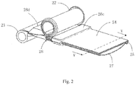
- the flexible screen module 20 includes a casing 21, a first rotating shaft 22, a second rotating shaft 23, a flexible screen 24, a bracket 25, a support member 27, and a buckling member 28.
- the casing 21 is provided with one opening 21a on one side thereof.
- the first rotating shaft 22 and the second rotating shaft 23 may be rotatably fixed in the casing 21, spaced apart from each other and substantially parallel to each other.
- the flexible screen 24 is substantially square and has one front surface for displaying images and one back surface opposite to the front surface (not illustrated in Figs. 2-3 ).
- One side of the front surface of the flexible screen 24 is fixed to the first rotating shaft 22, and the portion being fixed may be a non-display area at the edge of a front display area.
- the flexible screen 24 may be wound around the first rotating shaft 22, and may also be unwound from the first rotating shaft 22 and extended out of the casing 21 from the opening 21a.
- the bracket 25 includes a plurality of rigid bracket bodies 26.
- the plurality of bracket bodies 26 are disposed to parallel to one side at which the flexible screen 24 is fixed to the rotating shaft 22 (i.e., the axial direction of the first rotating shaft 22), and are fixed to the back of the flexible screen 24 at intervals by adhesion or the like.
- the plurality of bracket bodies 26 may be wound or unwound along with the flexible screen 24.
- each of the bracket bodies 26 includes one main body 26a fixed to the back of the flexible screen 24 and two coupling parts 26b respectively located on two opposite sides of the main body 26a.
- the main body 26a is rectangular and extends along the axial direction of the first rotating shaft 22 so as to support the flexible screen 24 in the axial direction.
- the coupling parts 26b extend along the direction away from the flexible screen 24 and towards the middle of the back of the flexible screen, thereby the coupling parts 26b can be curved into an arc.
- the coupling parts may be formed by bending the main body.
- bracket bodies 26 when the bracket bodies 26 are provided with chamfers inclined to each other at two opposite sides of two adjacent bracket bodies, the adjacent bracket bodies 26 may not be spaced apart from each other, but may be disposed in close contact. Due to the provision of the chamfers, the plurality of bracket bodies 26 disposed closely may also be wound around the first rotating shaft 22.
- the support member 27 is a substantially rectangular.
- the support member 27 has a curve memory characteristic in the width direction thereof.
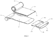
- the memory characteristic causes the support member 27 to remain curve in the width direction when it is not subjected to an external force, and the curve makes the support member 27 difficult to be bent, as illustrated by the support member 27 on the right side in Fig. 3 .
- the portion of the support member 27 which is bent becomes flat and can remain in the state of bending and automatically winding, as illustrated by the support member 27 on the left side in Fig. 3 , and the portion which is not bent remains curve in a certain degree.
- the portion of the support member 27 which is being curved but is not bent is engaged with the bracket bodies 26 as illustrated in Fig. 5 , that is, two sides of the support member 27 in the axial direction of the first rotation shaft 22 are engaged or accommodated in a space surrounded by the arc coupling parts 26b and the main body 26a, so as to support the bracket bodies 26 stretching out of the casing 21 in the direction in which the flexible screen 24 is extended.
- the portion of the support member 27 which is bent is wound around the second rotating shaft 23.
- the support member 27 may be made of a metal having a memory characteristic, such as a nickel-titanium alloy.
- the buckling member 28 includes a base 28a, two oppositely disposed squeezing parts 28b, and a substantially U-shaped pressing part 28c and a separating part 28d respectively located at two opposite sides of the two squeezing parts 28b.
- the squeezing parts 28b are fixed to the base 28a and extend to each other with a minimum pitch C smaller than distance B between the two opposite coupling parts 26b of the bracket bodies 26 at the side away from the main body 26a, so as to squeeze the support member 27.
- the base 28a and the pressing part 28c form a frame.
- the base 28a and the separating part 28d form another frame.
- the support member 27 passes through the pressing part 28c and the separating part 28d, and is squeezed by the squeezing parts 28b.
- the flexible screen 24 and the bracket 25 together pass through the pressing part 28c.
- the bracket 25 is coupled with the support member 27 in the pressing part 28c.
- the flexible screen 24 and the bracket 25 are located at one side of the separating part 28d which is opposite to the support member 27.
- one end of the support member 27 in the longitudinal direction is passed through the separating part 28d and is squeezed by the squeezing parts 28b, and the remaining portion is wound around the second rotating shaft 23.
- the flexible screen 24, together with the bracket 25, is wound around the first rotating shaft 22, the bracket bodies 26 at one end of the flexible screen sleeve the squeezed support member 27, and then the combination of the flexible screen 24, together with the bracket 25, and the support member 27 is passed through the pressing part 28c.
- the first and second rotating shafts 22, 23 are rotatably fixed to the casing 21 to complete the assembling of the flexible display module 15.
- the flexible display module 15 is assembled in the housing 16 of the electronic device 10 and the signal connection associated with the circuit board 15 is completed.
- the outlet 18 is aligned with the opening 21a so that the flexible screen 24 can be extended out of the housing 16.
- the flexible screen 24 can be pulled out manually by the user, in this case, a component fixedly connected with one side of the support member 27 and the flexible screen 24 that are adjacent to the outlet 18 may be disposed at the outside of the outlet 18 to be used for pulling.
- the flexible screen 24 can be pulled out in an electric manner; the second rotating shaft 23 may be driven by a motor 31 (illustrated in Fig. 1 ) fixed to the casing 21 to cause the support member 27 to drive the flexible screen 24 to extend outwardly, and in this case, the support member 27 close to one side of the outlet 18 is required to be fixedly connected with the bracket body 26.
- the first rotating shaft 22 may be driven by another motor 32.
- the portion of the support member 27 which moves to the squeezing parts 28b is squeezed and becomes narrower in width than the distance between the two opposite coupling parts 26b at the side of the coupling parts which is away from the main body 26a.
- the support member 27 has a curve memory characteristic in the axial direction of the first rotation shaft 22.
- the support member 27 When the support member 27 is extended along with the flexible screen 24 to the outside of the casing 21, it will curve in the axial direction of the first rotation shaft 22; in a direction substantially perpendicular to the axial direction, the support member 27 has certain rigidity and therefore is difficult to curve, so as to cooperate with the bracket 25 to support the flexible screen 24.
- the support member 27 is coupled with the bracket 25 once it is extended out of the casing 21, there is no need to manually couple them, and therefore, it is easy to operate. Further, the arrangement of the bracket 25 serves to support the flexible screen 24 such that the flexible screen 24 is not easily to deform towards the support member 27.
- the separating part 28d serves to separate the bracket 25 and the support member 27 before the bracket 25 is coupled with the support member 27.
- the flexible screen 24 and the bracket 25 substantially reach the squeezed support member 27 once they are unwound from the first rotating shaft 22, besides, the bracket 25 may also be smoothly coupled with the support member 27.
- the separating part 28d may be omitted.
- the pressing part 28c serves to ensure that relative positions of the bracket 25 and the support member 27 are not changed within an area for coupling, thereby ensuring the successful coupling between the bracket 25 and the support member 27.
- the opening 21a of the casing of the flexible screen module or the outlet 18 of the housing of the electronic device may also serves as the pressing part 28c as long as it has an appropriate width. Therefore, in other embodiments, the pressing part 28c may be omitted.
- the support member 27 will be bent and automatically wound upon being subjected to a force greater than a certain threshold value.
- the second rotating shaft 23 may not be provided, and the support member 27 may be automatically retracted by the contact of the casing 21 or the housing 16 or other components after the flexible screen 24 is retracted.
- the support member 27 is coupled to two sides of the bracket 25. However, it should be understood that, in other embodiments, the support member 27 may also be coupled to a position close to the middle of the bracket 25, as illustrated in Fig. 6 . In addition, in the embodiments described above, the support member 27 curves towards a direction away from the flexible screen 24 so as to make it difficult to be bent. However, it may be understood that the above effect will also be achieved when the support member 27 curves in a direction towards the flexible screen 24, as illustrated in Fig. 6 .
- the bracket may have an integrated structure, such as a bracket 25' illustrated in Fig. 7 .
- the bracket 25' may be integrally molded from a material having elasticity, such as thermoplastic polyurethane elastomer rubber (TPU).
- TPU thermoplastic polyurethane elastomer rubber
- coupling parts 25b on both sides of the bracket 25' curve towards the middle of the main body 25a.
- the functions of the coupling parts 25b are the same as those of the coupling parts 26b in the above-described embodiments.
- the coupling parts 25b are wound together with the flexible screen, the coupling parts 25b are deformed and attached to the main body 25a, and thus the overall thickness after winding can be reduced.
- the support member 27 when the support member 27 is coupled with the bracket 25', the support member 27 is preferably in a compressed state in the axial direction of the first rotating shaft 22, thereby enhancing the resistance to deformation of the main body 25a.
- the situation in which the support member 27 is compressed is also applicable to the above-described bracket bodies 26.
- the support member 27 is combined with the bracket 25 by engaging.
- the bracket 25 and the support member 27 when either of the bracket 25 and the support member 27 is provided as a magnetic material while the other is provided as a permeability magnetic material, they may be coupled with each other directly by magnetic force. In this manner, it is also possible to achieve the object of the above-described embodiments. In this situation, the bracket 25 may not be provided with the coupling parts.
- the arrangement of the casing 21 allows the flexible screen module to form a modular structure, and thus facilitate subsequent assembly in an electronic device. It should be understood, however, that the components in the flexible screen module except the casing 21 may be directly mounted in the housing 16 and the casing 21 may not be provided. Additionally, since the bracket 25 is fixed to the flexible screen 24, it is also possible that the bracket 25 being fixed to the first rotating shaft 22, which also allows the flexible screen 24 to be wound around the first rotating shaft 22.
Landscapes
- Engineering & Computer Science (AREA)
- Physics & Mathematics (AREA)
- Theoretical Computer Science (AREA)
- General Physics & Mathematics (AREA)
- Human Computer Interaction (AREA)
- General Engineering & Computer Science (AREA)
- Computer Hardware Design (AREA)
- Microelectronics & Electronic Packaging (AREA)
- Mathematical Physics (AREA)
- Nonlinear Science (AREA)
- Devices For Indicating Variable Information By Combining Individual Elements (AREA)
- Chemical & Material Sciences (AREA)
- Crystallography & Structural Chemistry (AREA)
- Optics & Photonics (AREA)
- Mounting Of Printed Circuit Boards And The Like (AREA)
Abstract
Description
- The present disclosure relates to a flexible screen, and particularly to a flexible screen module and an electronic device having the module.
- Existing mainstream screen module includes Liquid Crystal Display (LCD) module and Organic Light-Emitting Diode (OLED) module. The above two kinds of screen modules both have rigid glass substrates and therefore cannot be curved. Recently, due to the emergence of flexible OLED screen, the form of the screen module is no longer limited to the traditional plane. For example, the flexible screen may be rolled up like curtains. Since the screen is not rigid, when the screen is stretched out, it is related to a problem of how to support and fix the screen.
- One existing manner is to provide rotatable support rods on two opposite sides of an opening through which the flexible screen is stretched out. Before the flexible screen is pulled out, the two support rods are overlapped with each other. After the flexible screen is stretched out, the two support rods are rotated towards the direction of stretching the flexible screen to positions parallel to each other, so as to support the flexible screen. However, in this process, after the flexible screen is pulled out, it is necessary to manually rotate the support rods and fix them with the flexible screen, which is inconvenience. In addition, parts of the flexible screen not supported by the support rods are prone to deformation, which is unfavorable to the operation of the user.
- Embodiments of the present disclosure provide a flexible screen module for ease of use and an electronic device having the flexible screen module.
- A flexible screen module includes a casing, a flexible screen, a bracket, and a support member. The casing has an opening. A first rotating shaft has an axial direction and is accommodated in the casing. The flexible screen is capable of being wound around the first rotating shaft and is capable of being unwound from the first rotating shaft and being extended out of the casing through the opening. The bracket is fixed to the flexible screen and is capable of being wound around the first rotating shaft along with the flexible screen; the bracket supports the flexible screen in the axial direction. The support member is capable of being wound in the casing and being extended out of the casing along with the flexible screen. The support member has a curve memory characteristic in the axial direction. When located outside the casing, the support member is coupled with the bracket to support the bracket in the direction in which the flexible screen is extended.
- There is provided an electronic device having the flexible screen module described above.
- In the present disclosure, since the support member has a curve memory characteristic in the axial direction of the first rotating shaft, when it is extended to the outside of the casing along with the flexible screen, the support member may be curved in the axial direction of the first rotating shaft, and in the direction substantially perpendicular to the axial direction, the support member is not easy to be curved because of certain rigidity thereof. Therefore, the support member can cooperate with the bracket to support the flexible screen. Meanwhile, since the support member is coupled with a plurality of brackets once it is extended out of the casing, there is no need to manually couple them, and consequently, it is easy to operate.
- The following figures are used in conjunction with the embodiments to describe various embodiments of the present disclosure in detail. It should be understood that various elements schematically illustrated in the figures do not represent an actual size or proportional relationship, but are merely schematic views for clear description, and should not be construed as limiting the present disclosure.
-
Fig. 1 is a schematic view of an electronic device having a flexible display module according to a first embodiment of the present disclosure. -
Fig. 2 is a structural schematic view of the flexible display module of the electronic device inFig. 1 without the casing. -
Fig. 3 is a partial exploded structural schematic view of the flexible display module inFig. 2 , which illustrates a schematic diagram of the support member portion after being squeezed. -
Fig. 4 is a schematic view of a bracket and a flexible screen of the display module inFig. 2 in another viewing angle. -
Fig. 5 is a schematic cross-sectional view of a display module inFig. 2 along line V-V. -
Fig. 6 is an interface schematic view of another embodiment of the flexible display module inFig. 2 . -
Fig. 7 is a schematic view of another embodiment of the bracket of the flexible display module inFig. 2 . - In order to make objects, technical solutions and advantages of the present disclosure more clear, in the following, the present disclosure is further described in detail in conjunction with a plurality of embodiments and the figures. It should be understood that the embodiments described herein are merely for illustrating the present disclosure rather than limiting the present disclosure.
- Referring to
Fig. 1, Fig. 1 is a structural schematic view of anelectronic device 10 according to a first embodiment of the present disclosure. Theelectronic device 10 includes ahousing 16, and acircuit board 15 and aflexible display module 20 housed in thehousing 16. Thehousing 16 has anoutlet 18. The flexible screen of theflexible module 20 may be rolled up or unwound. When the flexible screen being unwound, it may be extended out of thehousing 16 through theoutlet 18 for viewing by the user. - Referring to
Figs. 2-3 , theflexible screen module 20 includes acasing 21, a first rotatingshaft 22, a second rotatingshaft 23, aflexible screen 24, abracket 25, asupport member 27, and abuckling member 28. Thecasing 21 is provided with one opening 21a on one side thereof. The first rotatingshaft 22 and the second rotatingshaft 23 may be rotatably fixed in thecasing 21, spaced apart from each other and substantially parallel to each other. - The
flexible screen 24 is substantially square and has one front surface for displaying images and one back surface opposite to the front surface (not illustrated inFigs. 2-3 ). One side of the front surface of theflexible screen 24 is fixed to the first rotatingshaft 22, and the portion being fixed may be a non-display area at the edge of a front display area. As such, theflexible screen 24 may be wound around the first rotatingshaft 22, and may also be unwound from the first rotatingshaft 22 and extended out of thecasing 21 from the opening 21a. - Referring to
Fig. 4 , thebracket 25 includes a plurality ofrigid bracket bodies 26. The plurality ofbracket bodies 26 are disposed to parallel to one side at which theflexible screen 24 is fixed to the rotating shaft 22 (i.e., the axial direction of the first rotating shaft 22), and are fixed to the back of theflexible screen 24 at intervals by adhesion or the like. As such, the plurality ofbracket bodies 26 may be wound or unwound along with theflexible screen 24. Specifically, each of thebracket bodies 26 includes onemain body 26a fixed to the back of theflexible screen 24 and twocoupling parts 26b respectively located on two opposite sides of themain body 26a. Themain body 26a is rectangular and extends along the axial direction of the first rotatingshaft 22 so as to support theflexible screen 24 in the axial direction. Thecoupling parts 26b extend along the direction away from theflexible screen 24 and towards the middle of the back of the flexible screen, thereby thecoupling parts 26b can be curved into an arc. The coupling parts may be formed by bending the main body. - It is to be noted that in other embodiments, when the
bracket bodies 26 are provided with chamfers inclined to each other at two opposite sides of two adjacent bracket bodies, theadjacent bracket bodies 26 may not be spaced apart from each other, but may be disposed in close contact. Due to the provision of the chamfers, the plurality ofbracket bodies 26 disposed closely may also be wound around the first rotatingshaft 22. - Referring to
Figs. 2-3 , thesupport member 27 is a substantially rectangular. Thesupport member 27 has a curve memory characteristic in the width direction thereof. The memory characteristic causes thesupport member 27 to remain curve in the width direction when it is not subjected to an external force, and the curve makes thesupport member 27 difficult to be bent, as illustrated by thesupport member 27 on the right side inFig. 3 . When the external force has removed after thesupport member 27 is bent by the external force, the portion of thesupport member 27 which is bent becomes flat and can remain in the state of bending and automatically winding, as illustrated by thesupport member 27 on the left side inFig. 3 , and the portion which is not bent remains curve in a certain degree. Distance A between the two sides in the width direction of thesupport member 27 in a curve state is larger than distance B between the twoopposite coupling parts 26b of thebracket bodies 26 at the side away from themain body 26a (as illustrated inFig. 4 ). In this way, the portion of thesupport member 27 which is being curved but is not bent is engaged with thebracket bodies 26 as illustrated inFig. 5 , that is, two sides of thesupport member 27 in the axial direction of thefirst rotation shaft 22 are engaged or accommodated in a space surrounded by thearc coupling parts 26b and themain body 26a, so as to support thebracket bodies 26 stretching out of thecasing 21 in the direction in which theflexible screen 24 is extended. The portion of thesupport member 27 which is bent is wound around the secondrotating shaft 23. Thesupport member 27 may be made of a metal having a memory characteristic, such as a nickel-titanium alloy. - The buckling
member 28 includes abase 28a, two oppositely disposed squeezingparts 28b, and a substantially U-shapedpressing part 28c and a separatingpart 28d respectively located at two opposite sides of the two squeezingparts 28b. The squeezingparts 28b are fixed to thebase 28a and extend to each other with a minimum pitch C smaller than distance B between the twoopposite coupling parts 26b of thebracket bodies 26 at the side away from themain body 26a, so as to squeeze thesupport member 27. Thebase 28a and thepressing part 28c form a frame. Thebase 28a and the separatingpart 28d form another frame. Thesupport member 27 passes through thepressing part 28c and the separatingpart 28d, and is squeezed by the squeezingparts 28b. Theflexible screen 24 and thebracket 25 together pass through thepressing part 28c. Thebracket 25 is coupled with thesupport member 27 in thepressing part 28c. Theflexible screen 24 and thebracket 25 are located at one side of the separatingpart 28d which is opposite to thesupport member 27. - During assembling, one end of the
support member 27 in the longitudinal direction is passed through the separatingpart 28d and is squeezed by the squeezingparts 28b, and the remaining portion is wound around the secondrotating shaft 23. Theflexible screen 24, together with thebracket 25, is wound around the firstrotating shaft 22, thebracket bodies 26 at one end of the flexible screen sleeve the squeezedsupport member 27, and then the combination of theflexible screen 24, together with thebracket 25, and thesupport member 27 is passed through thepressing part 28c. The first and secondrotating shafts casing 21 to complete the assembling of theflexible display module 15. Finally, theflexible display module 15 is assembled in thehousing 16 of theelectronic device 10 and the signal connection associated with thecircuit board 15 is completed. Theoutlet 18 is aligned with theopening 21a so that theflexible screen 24 can be extended out of thehousing 16. - During operation, when the
flexible screen 24 is needed to display an image, theflexible screen 24 can be pulled out manually by the user, in this case, a component fixedly connected with one side of thesupport member 27 and theflexible screen 24 that are adjacent to theoutlet 18 may be disposed at the outside of theoutlet 18 to be used for pulling. Alternatively, theflexible screen 24 can be pulled out in an electric manner; the secondrotating shaft 23 may be driven by a motor 31 (illustrated inFig. 1 ) fixed to thecasing 21 to cause thesupport member 27 to drive theflexible screen 24 to extend outwardly, and in this case, thesupport member 27 close to one side of theoutlet 18 is required to be fixedly connected with thebracket body 26. Of course, it may not be fixed, in which case the firstrotating shaft 22 may be driven by anothermotor 32. As theflexible screen 24 and thesupport member 27 are extended outwardly, the portion of thesupport member 27 which moves to the squeezingparts 28b is squeezed and becomes narrower in width than the distance between the twoopposite coupling parts 26b at the side of the coupling parts which is away from themain body 26a. - When the
flexible screen 24 and thesupport member 27 continue to be extended outwardly, theflexible screen 24 and thebracket bodies 26 will approach thesupport member 27 under the action of thepressing part 28c, so that the squeezedsupport member 27 can enter the space half-surrounded by thebracket bodies 26. As theflexible screen 24 and thesupport member 27 continue to be extended outwardly, thesupport member 27 is gradually moved away from the squeezingparts 28b to return to the original curve state, and is engaged or accommodated in the space surrounded by thearc coupling parts 26b and themain body 26a, so as to be coupled with thebracket bodies 26 and extended out of theoutlet 18. When theflexible screen 24 is not needed, it can also be retracted into thehousing 16 in a manual or electric manner. This process is contrary to the above-mentioned pull-out process and may be understood by those skilled in the art from the foregoing description, and is not described herein. - The
support member 27 has a curve memory characteristic in the axial direction of thefirst rotation shaft 22. When thesupport member 27 is extended along with theflexible screen 24 to the outside of thecasing 21, it will curve in the axial direction of thefirst rotation shaft 22; in a direction substantially perpendicular to the axial direction, thesupport member 27 has certain rigidity and therefore is difficult to curve, so as to cooperate with thebracket 25 to support theflexible screen 24. Meanwhile, since thesupport member 27 is coupled with thebracket 25 once it is extended out of thecasing 21, there is no need to manually couple them, and therefore, it is easy to operate. Further, the arrangement of thebracket 25 serves to support theflexible screen 24 such that theflexible screen 24 is not easily to deform towards thesupport member 27. - The separating
part 28d serves to separate thebracket 25 and thesupport member 27 before thebracket 25 is coupled with thesupport member 27. However, it may be understood that, in other embodiments, theflexible screen 24 and thebracket 25 substantially reach the squeezedsupport member 27 once they are unwound from the firstrotating shaft 22, besides, thebracket 25 may also be smoothly coupled with thesupport member 27. In this case, the separatingpart 28d may be omitted. - The
pressing part 28c serves to ensure that relative positions of thebracket 25 and thesupport member 27 are not changed within an area for coupling, thereby ensuring the successful coupling between thebracket 25 and thesupport member 27. However, it may be understood that theopening 21a of the casing of the flexible screen module or theoutlet 18 of the housing of the electronic device may also serves as thepressing part 28c as long as it has an appropriate width. Therefore, in other embodiments, thepressing part 28c may be omitted. - As described in the above embodiments, the
support member 27 will be bent and automatically wound upon being subjected to a force greater than a certain threshold value. Thus, in other embodiments, the secondrotating shaft 23 may not be provided, and thesupport member 27 may be automatically retracted by the contact of thecasing 21 or thehousing 16 or other components after theflexible screen 24 is retracted. - In the embodiments described above, the
support member 27 is coupled to two sides of thebracket 25. However, it should be understood that, in other embodiments, thesupport member 27 may also be coupled to a position close to the middle of thebracket 25, as illustrated inFig. 6 . In addition, in the embodiments described above, thesupport member 27 curves towards a direction away from theflexible screen 24 so as to make it difficult to be bent. However, it may be understood that the above effect will also be achieved when thesupport member 27 curves in a direction towards theflexible screen 24, as illustrated inFig. 6 . - In other embodiments, instead of being composed of a plurality of
bracket bodies 26 spaced apart, the bracket may have an integrated structure, such as a bracket 25' illustrated inFig. 7 . In this situation, the bracket 25' may be integrally molded from a material having elasticity, such as thermoplastic polyurethane elastomer rubber (TPU). When no external force is applied, couplingparts 25b on both sides of the bracket 25' curve towards the middle of themain body 25a. The functions of thecoupling parts 25b are the same as those of thecoupling parts 26b in the above-described embodiments. When thecoupling parts 25b are wound together with the flexible screen, thecoupling parts 25b are deformed and attached to themain body 25a, and thus the overall thickness after winding can be reduced. In addition, when thesupport member 27 is coupled with the bracket 25', thesupport member 27 is preferably in a compressed state in the axial direction of the firstrotating shaft 22, thereby enhancing the resistance to deformation of themain body 25a. Of course, the situation in which thesupport member 27 is compressed is also applicable to the above-describedbracket bodies 26. - In the above-described embodiments, the
support member 27 is combined with thebracket 25 by engaging. However, it may be understood that, in other embodiments, when either of thebracket 25 and thesupport member 27 is provided as a magnetic material while the other is provided as a permeability magnetic material, they may be coupled with each other directly by magnetic force. In this manner, it is also possible to achieve the object of the above-described embodiments. In this situation, thebracket 25 may not be provided with the coupling parts. - The arrangement of the
casing 21 allows the flexible screen module to form a modular structure, and thus facilitate subsequent assembly in an electronic device. It should be understood, however, that the components in the flexible screen module except thecasing 21 may be directly mounted in thehousing 16 and thecasing 21 may not be provided. Additionally, since thebracket 25 is fixed to theflexible screen 24, it is also possible that thebracket 25 being fixed to the firstrotating shaft 22, which also allows theflexible screen 24 to be wound around the firstrotating shaft 22. - The above is merely for preferable embodiments of the present disclosure and not intended to limit the present disclosure. Any modifications, equivalent substitutions and improvements and so on within the spirit and principle of the present disclosure should fall within the scope of protection of the present disclosure.
Claims (20)
- A flexible screen module, comprising:a casing comprising an opening;a first rotating shaft comprising an axial direction and being accommodated in the casing;a flexible screen capable of being wound around the first rotating shaft, and capable of being unwound from the first rotating shaft and extended out of the casing through the opening;a bracket fixed to the flexible screen and capable of being wound around the first rotating shaft along with the flexible screen, the bracket supporting the flexible screen in the axial direction; anda support member capable of being wound in the casing and capable of being extended out of the casing along with the flexible screen, the support member comprising a curve memory characteristic in the axial direction; when located outside the casing, the support member being coupled with the bracket to support the bracket in a direction in which the flexible screen is extended.
- The flexible screen module according to claim 1, further comprising a second rotating shaft rotatably accommodated in the casing, the support member being capable of being wound around the second rotating shaft.
- The flexible screen module according to claim 2, further comprising a drive apparatus fixed to the casing, wherein the support member has one end fixed to the second rotating shaft, and the drive apparatus is configured to drive the second rotating shaft to rotate such that the support member is extended out of the casing or wound into the casing.
- The flexible screen module according to claim 1, wherein the bracket comprises a plurality of bracket bodies disposed in the axial direction and fixed to the flexible screen.
- The flexible screen module according to any of claims 1 to 4, wherein the bracket and the support member are coupled with each other via magnetic force.
- The flexible screen module according to claim 1, further comprising a buckling member comprising squeezing parts disposed oppositely, the squeezing parts being configured to squeez the support member in the axial direction such that the support member is coupled with the bracket.
- The flexible screen module according to claim 6, wherein the support member curves towards a direction away from the flexible screen.
- The flexible screen module according to claim 6, wherein the bracket comprises a main body fixed to the flexible screen and two coupling parts disposed oppositely in the axial direction, and two opposite sides of the support member which are located in the axial direction are coupled with the two coupling parts.
- The flexible screen module according to claim 8, wherein the two coupling parts disposed oppositely are located on two sides of the main body in the axial direction.
- The flexible screen module according to any of claims 6 to 9, wherein the support member is in a compressed state in the axial direction when the support member is coupled with the bracket.
- The flexible screen module according to claim 6, wherein the buckling member further comprises a pressing part located at one side of the squeezing parts, and after being squeezed by the squeezing parts, the support member deforms into an original curve state in the pressing part and is coupled with the two coupling parts.
- The flexible screen module according to claim 6 or 11, wherein the buckling member further comprises a separating part located at another side of the squeezing parts, and when the support member is moved towards the opening, the support member and the bracket are respectively located at two sides of the separating part before the support member is squeezed by the squeezing parts.
- An electronic device, comprising a flexible screen module according to any of claims 1 to 12.
- An electronic device, comprising:a housing comprising an outlet; anda flexible screen module accommodated in the housing and comprising:a first rotating shaft comprising an axial direction and accommodated in the housing;a flexible screen capable of being wound around the first rotating shaft and capable of being unwound from the first rotating shaft and extended out of the housing through the outlet;a bracket fixed to the flexible screen and capable of being wound around the first rotating shaft along with the flexible screen, the bracket supporting the flexible screen in the axial direction; anda support member capable of being wound in the housing and capable of being extended out of the housing along with the flexible screen; the support member comprising a curve memory characteristic in the axial direction, wherein, when located outside the housing, the support member is coupled with the bracket to support the bracket in the direction in which the flexible screen is extended.
- The electronic device according to claim 14, further comprising a second rotating shaft rotatably accommodated in the housing and a drive apparatus, wherein the support member has one end fixed to the second rotating shaft, the support member is capable of being wound around the second rotating shaft, and the drive apparatus is configured to drive the second rotating shaft to rotate such that the support member is extended out of the housing or wound into the housing.
- The electronic device according to claim 14, wherein the bracket and the support member are coupled with each other via magnetic force.
- The electronic device according to claim 14, further comprising a buckling member comprising squeezing parts disposed oppositely, the squeezing parts being configured to squeeze the support member in the axial direction such that the support member is coupled with the bracket.
- The electronic device according to claim 17, wherein the bracket comprises a main body fixed to the flexible screen and two coupling parts disposed oppositely in the axial direction, and the support member is in a compressed state in the axial direction when two opposite sides of the support member which are located in the axial direction are coupled with the two coupling parts.
- The electronic device according to claim 17 or 18, wherein the support member curves towards a direction away from the flexible screen.
- The electronic device according to claim 17, wherein the buckling member further comprises a pressing part located at one side of the squeezing parts, and after being squeezed by the squeezing parts, the support member returns to an original curve state and is coupled with the two coupling parts in the pressing part.
Applications Claiming Priority (1)
| Application Number | Priority Date | Filing Date | Title |
|---|---|---|---|
| PCT/CN2014/089773 WO2016065549A1 (en) | 2014-10-29 | 2014-10-29 | Flexible screen module and electronic device having the module |
Publications (3)
| Publication Number | Publication Date |
|---|---|
| EP3196730A1 true EP3196730A1 (en) | 2017-07-26 |
| EP3196730A4 EP3196730A4 (en) | 2018-06-13 |
| EP3196730B1 EP3196730B1 (en) | 2019-07-17 |
Family
ID=55856369
Family Applications (1)
| Application Number | Title | Priority Date | Filing Date |
|---|---|---|---|
| EP14904978.5A Not-in-force EP3196730B1 (en) | 2014-10-29 | 2014-10-29 | Flexible screen module and electronic device having the module |
Country Status (7)
| Country | Link |
|---|---|
| US (1) | US10045448B2 (en) |
| EP (1) | EP3196730B1 (en) |
| JP (1) | JP6472880B2 (en) |
| KR (1) | KR101930658B1 (en) |
| CN (1) | CN105723295B (en) |
| ES (1) | ES2744861T3 (en) |
| WO (1) | WO2016065549A1 (en) |
Families Citing this family (32)
| Publication number | Priority date | Publication date | Assignee | Title |
|---|---|---|---|---|
| KR102493527B1 (en) * | 2016-07-05 | 2023-02-01 | 삼성디스플레이 주식회사 | Rollable display device and electronic device including the same |
| CN105979037B (en) * | 2016-07-08 | 2018-11-16 | 广东欧珀移动通信有限公司 | Flexible screen supporting structure, flexible display screen module and mobile terminal |
| KR102697976B1 (en) * | 2016-08-29 | 2024-08-22 | 삼성디스플레이 주식회사 | Rollable display device |
| CN106302885A (en) * | 2016-09-28 | 2017-01-04 | 珠海凯邦电机制造有限公司 | Mobile terminal |
| CN107995961B (en) * | 2016-12-29 | 2020-10-27 | 深圳市柔宇科技有限公司 | Intelligent terminal and control method thereof |
| CN107423021A (en) * | 2017-07-28 | 2017-12-01 | 联想(北京)有限公司 | A kind of smart machine and intelligent control method |
| CN108076175A (en) * | 2017-12-21 | 2018-05-25 | 广东长盈精密技术有限公司 | A kind of mobile terminal |
| CN110891100B (en) * | 2018-09-07 | 2025-08-05 | 北京小米移动软件有限公司 | terminal |
| KR102519817B1 (en) * | 2018-11-08 | 2023-04-07 | 엘지디스플레이 주식회사 | Display device |
| CN111263541A (en) * | 2018-11-30 | 2020-06-09 | 北京小米移动软件有限公司 | Foldable device and installation method |
| CN109587299A (en) * | 2018-12-05 | 2019-04-05 | 邹耿彪 | A kind of mobile communication terminal of screen rollable |
| CN109455580A (en) * | 2018-12-27 | 2019-03-12 | 重庆玮硕恒基电脑配件有限公司 | A kind of flexible screen collector |
| CN109725773B (en) * | 2018-12-29 | 2021-09-24 | 维沃移动通信有限公司 | A control method and terminal of a flexible screen |
| CN111090299B (en) * | 2019-04-19 | 2024-11-22 | 广东小天才科技有限公司 | Dual screen eye protection tablet |
| CN110277024B (en) * | 2019-06-25 | 2021-09-21 | 武汉天马微电子有限公司 | Flexible display device |
| CN112306147B (en) * | 2019-07-24 | 2024-03-26 | 北京小米移动软件有限公司 | Flexible screen support structure, flexible screen structure and terminal equipment |
| WO2021012252A1 (en) * | 2019-07-25 | 2021-01-28 | 深圳市柔宇科技有限公司 | Flexible display device and terminal |
| CN110728912B (en) * | 2019-10-23 | 2021-12-07 | Oppo(重庆)智能科技有限公司 | Flexible screen assembly and electronic equipment |
| CN111157358B (en) * | 2020-01-10 | 2023-06-23 | 昆山国显光电有限公司 | Reel and flexible screen body testing device |
| CN114005357B (en) * | 2020-07-28 | 2023-07-14 | 华为技术有限公司 | Screen support device and electronic equipment |
| CN112382200B (en) * | 2020-11-13 | 2023-07-25 | 京东方科技集团股份有限公司 | display device |
| WO2022119337A1 (en) | 2020-12-02 | 2022-06-09 | 삼성전자주식회사 | Electronic device |
| WO2022141005A1 (en) * | 2020-12-28 | 2022-07-07 | 昆山国显光电有限公司 | Flexible display panel and display device |
| CN112863345B (en) * | 2021-01-13 | 2022-06-03 | 山西卓安物资贸易有限公司 | Construction site safety work demonstration equipment based on VR technique |
| CN115250301A (en) * | 2021-04-27 | 2022-10-28 | Oppo广东移动通信有限公司 | Electronic equipment |
| CN113325924B (en) * | 2021-05-24 | 2024-02-06 | 维沃移动通信有限公司 | Electronic equipment |
| CN115412622B (en) * | 2021-05-28 | 2026-03-20 | 北京小米移动软件有限公司 | Opening mechanism and electronic equipment |
| CN114268682B (en) * | 2021-12-28 | 2025-02-21 | Oppo广东移动通信有限公司 | Flexible screen supporting device and electronic device |
| KR102891636B1 (en) | 2021-12-30 | 2025-11-27 | 엘지디스플레이 주식회사 | Display device |
| KR20230102975A (en) | 2021-12-30 | 2023-07-07 | 엘지디스플레이 주식회사 | Display device |
| KR102903784B1 (en) * | 2022-01-17 | 2025-12-24 | 삼성디스플레이 주식회사 | Display device |
| CN115234772B (en) * | 2022-07-20 | 2026-01-09 | 维沃移动通信有限公司 | electronic devices |
Family Cites Families (19)
| Publication number | Priority date | Publication date | Assignee | Title |
|---|---|---|---|---|
| JPS5136532Y2 (en) * | 1972-05-18 | 1976-09-08 | ||
| JPS5240942B2 (en) | 1972-06-14 | 1977-10-15 | ||
| JPS5877331A (en) | 1981-11-04 | 1983-05-10 | Hitachi Ltd | Logical circuit |
| JPS5877331U (en) * | 1981-11-17 | 1983-05-25 | 株式会社キクチ科学研究所 | Roll-up curved screen device |
| JP3576298B2 (en) * | 1995-12-05 | 2004-10-13 | 大日本印刷株式会社 | Screen device |
| JPH10221780A (en) * | 1997-02-05 | 1998-08-21 | Dainippon Printing Co Ltd | Screen device |
| FI103220B (en) * | 1997-06-24 | 1999-05-14 | Nokia Mobile Phones Ltd | Screen |
| AU2002230610A1 (en) * | 2000-12-05 | 2002-06-18 | E-Ink Corporation | Portable eclectronic apparatus with additional electro-optical display |
| WO2006085271A2 (en) * | 2005-02-11 | 2006-08-17 | Polymer Vision Limited | Wrap display system having a flexible display |
| JP4943425B2 (en) | 2005-05-20 | 2012-05-30 | クリエーター テクノロジー ビー ヴィ | Protective cover for flexible display screen |
| JP3119961U (en) * | 2005-07-22 | 2006-03-23 | 株式会社ロケット・アイズ | screen |
| US7639237B2 (en) * | 2006-03-03 | 2009-12-29 | Perkins Michael T | Roll-out touch screen support system (ROTS3) |
| JP2008052040A (en) * | 2006-08-24 | 2008-03-06 | Fujifilm Corp | Display device |
| US20080247126A1 (en) * | 2007-04-04 | 2008-10-09 | Motorola, Inc. | Retractable display assembly and electronic device |
| US8493726B2 (en) * | 2007-04-25 | 2013-07-23 | Creator Technology B.V. | Electronic device comprising a flexible display with edge protectors |
| JP2011022260A (en) | 2009-07-14 | 2011-02-03 | Seiko Epson Corp | Screen |
| CN203057227U (en) * | 2012-12-19 | 2013-07-10 | 浙江中呼科技有限公司 | Scroll type smart phone |
| TWI655807B (en) * | 2013-08-27 | 2019-04-01 | 飛利斯有限公司 | Attachable device having a flexible electronic component |
| CN103712052B (en) * | 2013-12-31 | 2016-03-30 | 吉首大学 | A kind of rollable thin-walled supporting structure |
-
2014
- 2014-10-29 WO PCT/CN2014/089773 patent/WO2016065549A1/en not_active Ceased
- 2014-10-29 CN CN201480003345.0A patent/CN105723295B/en not_active Expired - Fee Related
- 2014-10-29 JP JP2017523855A patent/JP6472880B2/en not_active Expired - Fee Related
- 2014-10-29 KR KR1020177014325A patent/KR101930658B1/en not_active Expired - Fee Related
- 2014-10-29 EP EP14904978.5A patent/EP3196730B1/en not_active Not-in-force
- 2014-10-29 US US15/521,059 patent/US10045448B2/en not_active Expired - Fee Related
- 2014-10-29 ES ES14904978T patent/ES2744861T3/en active Active
Also Published As
| Publication number | Publication date |
|---|---|
| EP3196730B1 (en) | 2019-07-17 |
| JP6472880B2 (en) | 2019-02-20 |
| JP2017536573A (en) | 2017-12-07 |
| CN105723295B (en) | 2020-02-07 |
| WO2016065549A1 (en) | 2016-05-06 |
| CN105723295A8 (en) | 2017-07-18 |
| US20170311461A1 (en) | 2017-10-26 |
| ES2744861T3 (en) | 2020-02-26 |
| KR101930658B1 (en) | 2018-12-18 |
| CN105723295A (en) | 2016-06-29 |
| KR20170072329A (en) | 2017-06-26 |
| EP3196730A4 (en) | 2018-06-13 |
| US10045448B2 (en) | 2018-08-07 |
Similar Documents
| Publication | Publication Date | Title |
|---|---|---|
| US10045448B2 (en) | Flexible screen module and electronic device having the module | |
| CN105723818B (en) | Electronic device with flexible screen | |
| CN106340254B (en) | Display device | |
| CN205943347U (en) | Flexible display device and mobile terminal | |
| US20200196459A1 (en) | Flexible display device and mobile terminal | |
| CN110491289A (en) | Display device | |
| EP3796074A1 (en) | Display device | |
| WO2022042534A1 (en) | Electronic device | |
| EP3712875A1 (en) | Structure of extending-type display screen | |
| CN107545849A (en) | Flexible display apparatus | |
| CN203746358U (en) | Flexible display device | |
| CN209543792U (en) | A kind of flexible display device and electronic display equipment | |
| RU2016105816A (en) | FLEXIBLE DISPLAY UNIT FOR FOLDING PORTABLE TERMINAL (OPTIONS) AND FOLDING PORTABLE TERMINAL (OPTIONS) | |
| US20170280571A1 (en) | Flexible screen module and electronic device having the module | |
| EP1621968A3 (en) | Liquid crystal display device protection structure for electronic equipment | |
| US20150011269A1 (en) | Portable electronic device | |
| KR20170057500A (en) | Foldable display apparatus | |
| CN104407461A (en) | Curved surface liquid crystal display device | |
| CN104090368B (en) | One kind slides flip structure | |
| CN114882798B (en) | Foldable electronic equipment and pressing mechanism thereof | |
| CN104900156A (en) | Display device | |
| CN114283697B (en) | Folding device and display equipment | |
| CN101649950A (en) | Bracket | |
| CN206451084U (en) | A kind of display and mobile terminal | |
| CN210091606U (en) | Flexible display device |
Legal Events
| Date | Code | Title | Description |
|---|---|---|---|
| STAA | Information on the status of an ep patent application or granted ep patent |
Free format text: STATUS: THE INTERNATIONAL PUBLICATION HAS BEEN MADE |
|
| PUAI | Public reference made under article 153(3) epc to a published international application that has entered the european phase |
Free format text: ORIGINAL CODE: 0009012 |
|
| STAA | Information on the status of an ep patent application or granted ep patent |
Free format text: STATUS: REQUEST FOR EXAMINATION WAS MADE |
|
| 17P | Request for examination filed |
Effective date: 20170421 |
|
| AK | Designated contracting states |
Kind code of ref document: A1 Designated state(s): AL AT BE BG CH CY CZ DE DK EE ES FI FR GB GR HR HU IE IS IT LI LT LU LV MC MK MT NL NO PL PT RO RS SE SI SK SM TR |
|
| AX | Request for extension of the european patent |
Extension state: BA ME |
|
| DAX | Request for extension of the european patent (deleted) | ||
| A4 | Supplementary search report drawn up and despatched |
Effective date: 20180516 |
|
| RIC1 | Information provided on ipc code assigned before grant |
Ipc: G02F 1/01 20060101ALI20180509BHEP Ipc: G06F 1/16 20060101AFI20180509BHEP Ipc: H05K 5/02 20060101ALI20180509BHEP |
|
| GRAP | Despatch of communication of intention to grant a patent |
Free format text: ORIGINAL CODE: EPIDOSNIGR1 |
|
| STAA | Information on the status of an ep patent application or granted ep patent |
Free format text: STATUS: GRANT OF PATENT IS INTENDED |
|
| INTG | Intention to grant announced |
Effective date: 20190328 |
|
| GRAS | Grant fee paid |
Free format text: ORIGINAL CODE: EPIDOSNIGR3 |
|
| GRAA | (expected) grant |
Free format text: ORIGINAL CODE: 0009210 |
|
| STAA | Information on the status of an ep patent application or granted ep patent |
Free format text: STATUS: THE PATENT HAS BEEN GRANTED |
|
| AK | Designated contracting states |
Kind code of ref document: B1 Designated state(s): AL AT BE BG CH CY CZ DE DK EE ES FI FR GB GR HR HU IE IS IT LI LT LU LV MC MK MT NL NO PL PT RO RS SE SI SK SM TR |
|
| REG | Reference to a national code |
Ref country code: GB Ref legal event code: FG4D |
|
| REG | Reference to a national code |
Ref country code: CH Ref legal event code: EP |
|
| REG | Reference to a national code |
Ref country code: IE Ref legal event code: FG4D |
|
| REG | Reference to a national code |
Ref country code: DE Ref legal event code: R096 Ref document number: 602014050309 Country of ref document: DE |
|
| REG | Reference to a national code |
Ref country code: AT Ref legal event code: REF Ref document number: 1156427 Country of ref document: AT Kind code of ref document: T Effective date: 20190815 |
|
| REG | Reference to a national code |
Ref country code: NL Ref legal event code: FP |
|
| REG | Reference to a national code |
Ref country code: LT Ref legal event code: MG4D |
|
| REG | Reference to a national code |
Ref country code: AT Ref legal event code: MK05 Ref document number: 1156427 Country of ref document: AT Kind code of ref document: T Effective date: 20190717 |
|
| PG25 | Lapsed in a contracting state [announced via postgrant information from national office to epo] |
Ref country code: NO Free format text: LAPSE BECAUSE OF FAILURE TO SUBMIT A TRANSLATION OF THE DESCRIPTION OR TO PAY THE FEE WITHIN THE PRESCRIBED TIME-LIMIT Effective date: 20191017 Ref country code: AT Free format text: LAPSE BECAUSE OF FAILURE TO SUBMIT A TRANSLATION OF THE DESCRIPTION OR TO PAY THE FEE WITHIN THE PRESCRIBED TIME-LIMIT Effective date: 20190717 Ref country code: HR Free format text: LAPSE BECAUSE OF FAILURE TO SUBMIT A TRANSLATION OF THE DESCRIPTION OR TO PAY THE FEE WITHIN THE PRESCRIBED TIME-LIMIT Effective date: 20190717 Ref country code: SE Free format text: LAPSE BECAUSE OF FAILURE TO SUBMIT A TRANSLATION OF THE DESCRIPTION OR TO PAY THE FEE WITHIN THE PRESCRIBED TIME-LIMIT Effective date: 20190717 Ref country code: FI Free format text: LAPSE BECAUSE OF FAILURE TO SUBMIT A TRANSLATION OF THE DESCRIPTION OR TO PAY THE FEE WITHIN THE PRESCRIBED TIME-LIMIT Effective date: 20190717 Ref country code: LT Free format text: LAPSE BECAUSE OF FAILURE TO SUBMIT A TRANSLATION OF THE DESCRIPTION OR TO PAY THE FEE WITHIN THE PRESCRIBED TIME-LIMIT Effective date: 20190717 Ref country code: BG Free format text: LAPSE BECAUSE OF FAILURE TO SUBMIT A TRANSLATION OF THE DESCRIPTION OR TO PAY THE FEE WITHIN THE PRESCRIBED TIME-LIMIT Effective date: 20191017 Ref country code: PT Free format text: LAPSE BECAUSE OF FAILURE TO SUBMIT A TRANSLATION OF THE DESCRIPTION OR TO PAY THE FEE WITHIN THE PRESCRIBED TIME-LIMIT Effective date: 20191118 |
|
| PGFP | Annual fee paid to national office [announced via postgrant information from national office to epo] |
Ref country code: NL Payment date: 20190925 Year of fee payment: 6 Ref country code: DE Payment date: 20191009 Year of fee payment: 6 |
|
| REG | Reference to a national code |
Ref country code: ES Ref legal event code: FG2A Ref document number: 2744861 Country of ref document: ES Kind code of ref document: T3 Effective date: 20200226 |
|
| PG25 | Lapsed in a contracting state [announced via postgrant information from national office to epo] |
Ref country code: GR Free format text: LAPSE BECAUSE OF FAILURE TO SUBMIT A TRANSLATION OF THE DESCRIPTION OR TO PAY THE FEE WITHIN THE PRESCRIBED TIME-LIMIT Effective date: 20191018 Ref country code: AL Free format text: LAPSE BECAUSE OF FAILURE TO SUBMIT A TRANSLATION OF THE DESCRIPTION OR TO PAY THE FEE WITHIN THE PRESCRIBED TIME-LIMIT Effective date: 20190717 Ref country code: LV Free format text: LAPSE BECAUSE OF FAILURE TO SUBMIT A TRANSLATION OF THE DESCRIPTION OR TO PAY THE FEE WITHIN THE PRESCRIBED TIME-LIMIT Effective date: 20190717 Ref country code: RS Free format text: LAPSE BECAUSE OF FAILURE TO SUBMIT A TRANSLATION OF THE DESCRIPTION OR TO PAY THE FEE WITHIN THE PRESCRIBED TIME-LIMIT Effective date: 20190717 Ref country code: IS Free format text: LAPSE BECAUSE OF FAILURE TO SUBMIT A TRANSLATION OF THE DESCRIPTION OR TO PAY THE FEE WITHIN THE PRESCRIBED TIME-LIMIT Effective date: 20191117 |
|
| PGFP | Annual fee paid to national office [announced via postgrant information from national office to epo] |
Ref country code: FR Payment date: 20191031 Year of fee payment: 6 Ref country code: BE Payment date: 20191025 Year of fee payment: 6 Ref country code: ES Payment date: 20191119 Year of fee payment: 6 |
|
| PG25 | Lapsed in a contracting state [announced via postgrant information from national office to epo] |
Ref country code: TR Free format text: LAPSE BECAUSE OF FAILURE TO SUBMIT A TRANSLATION OF THE DESCRIPTION OR TO PAY THE FEE WITHIN THE PRESCRIBED TIME-LIMIT Effective date: 20190717 |
|
| PG25 | Lapsed in a contracting state [announced via postgrant information from national office to epo] |
Ref country code: RO Free format text: LAPSE BECAUSE OF FAILURE TO SUBMIT A TRANSLATION OF THE DESCRIPTION OR TO PAY THE FEE WITHIN THE PRESCRIBED TIME-LIMIT Effective date: 20190717 Ref country code: PL Free format text: LAPSE BECAUSE OF FAILURE TO SUBMIT A TRANSLATION OF THE DESCRIPTION OR TO PAY THE FEE WITHIN THE PRESCRIBED TIME-LIMIT Effective date: 20190717 Ref country code: EE Free format text: LAPSE BECAUSE OF FAILURE TO SUBMIT A TRANSLATION OF THE DESCRIPTION OR TO PAY THE FEE WITHIN THE PRESCRIBED TIME-LIMIT Effective date: 20190717 Ref country code: IT Free format text: LAPSE BECAUSE OF FAILURE TO SUBMIT A TRANSLATION OF THE DESCRIPTION OR TO PAY THE FEE WITHIN THE PRESCRIBED TIME-LIMIT Effective date: 20190717 Ref country code: DK Free format text: LAPSE BECAUSE OF FAILURE TO SUBMIT A TRANSLATION OF THE DESCRIPTION OR TO PAY THE FEE WITHIN THE PRESCRIBED TIME-LIMIT Effective date: 20190717 |
|
| PGFP | Annual fee paid to national office [announced via postgrant information from national office to epo] |
Ref country code: GB Payment date: 20191018 Year of fee payment: 6 |
|
| PG25 | Lapsed in a contracting state [announced via postgrant information from national office to epo] |
Ref country code: MC Free format text: LAPSE BECAUSE OF FAILURE TO SUBMIT A TRANSLATION OF THE DESCRIPTION OR TO PAY THE FEE WITHIN THE PRESCRIBED TIME-LIMIT Effective date: 20190717 Ref country code: SM Free format text: LAPSE BECAUSE OF FAILURE TO SUBMIT A TRANSLATION OF THE DESCRIPTION OR TO PAY THE FEE WITHIN THE PRESCRIBED TIME-LIMIT Effective date: 20190717 Ref country code: IS Free format text: LAPSE BECAUSE OF FAILURE TO SUBMIT A TRANSLATION OF THE DESCRIPTION OR TO PAY THE FEE WITHIN THE PRESCRIBED TIME-LIMIT Effective date: 20200224 Ref country code: SK Free format text: LAPSE BECAUSE OF FAILURE TO SUBMIT A TRANSLATION OF THE DESCRIPTION OR TO PAY THE FEE WITHIN THE PRESCRIBED TIME-LIMIT Effective date: 20190717 Ref country code: CZ Free format text: LAPSE BECAUSE OF FAILURE TO SUBMIT A TRANSLATION OF THE DESCRIPTION OR TO PAY THE FEE WITHIN THE PRESCRIBED TIME-LIMIT Effective date: 20190717 |
|
| REG | Reference to a national code |
Ref country code: CH Ref legal event code: PL |
|
| REG | Reference to a national code |
Ref country code: DE Ref legal event code: R097 Ref document number: 602014050309 Country of ref document: DE |
|
| PLBE | No opposition filed within time limit |
Free format text: ORIGINAL CODE: 0009261 |
|
| STAA | Information on the status of an ep patent application or granted ep patent |
Free format text: STATUS: NO OPPOSITION FILED WITHIN TIME LIMIT |
|
| PG2D | Information on lapse in contracting state deleted |
Ref country code: IS |
|
| PG25 | Lapsed in a contracting state [announced via postgrant information from national office to epo] |
Ref country code: LI Free format text: LAPSE BECAUSE OF NON-PAYMENT OF DUE FEES Effective date: 20191031 Ref country code: LU Free format text: LAPSE BECAUSE OF NON-PAYMENT OF DUE FEES Effective date: 20191029 Ref country code: CH Free format text: LAPSE BECAUSE OF NON-PAYMENT OF DUE FEES Effective date: 20191031 |
|
| 26N | No opposition filed |
Effective date: 20200603 |
|
| PG25 | Lapsed in a contracting state [announced via postgrant information from national office to epo] |
Ref country code: SI Free format text: LAPSE BECAUSE OF FAILURE TO SUBMIT A TRANSLATION OF THE DESCRIPTION OR TO PAY THE FEE WITHIN THE PRESCRIBED TIME-LIMIT Effective date: 20190717 |
|
| PG25 | Lapsed in a contracting state [announced via postgrant information from national office to epo] |
Ref country code: IE Free format text: LAPSE BECAUSE OF NON-PAYMENT OF DUE FEES Effective date: 20191029 |
|
| REG | Reference to a national code |
Ref country code: DE Ref legal event code: R119 Ref document number: 602014050309 Country of ref document: DE |
|
| PG25 | Lapsed in a contracting state [announced via postgrant information from national office to epo] |
Ref country code: CY Free format text: LAPSE BECAUSE OF FAILURE TO SUBMIT A TRANSLATION OF THE DESCRIPTION OR TO PAY THE FEE WITHIN THE PRESCRIBED TIME-LIMIT Effective date: 20190717 |
|
| REG | Reference to a national code |
Ref country code: NL Ref legal event code: MM Effective date: 20201101 |
|
| GBPC | Gb: european patent ceased through non-payment of renewal fee |
Effective date: 20201029 |
|
| REG | Reference to a national code |
Ref country code: BE Ref legal event code: MM Effective date: 20201031 |
|
| PG25 | Lapsed in a contracting state [announced via postgrant information from national office to epo] |
Ref country code: DE Free format text: LAPSE BECAUSE OF NON-PAYMENT OF DUE FEES Effective date: 20210501 Ref country code: FR Free format text: LAPSE BECAUSE OF NON-PAYMENT OF DUE FEES Effective date: 20201031 Ref country code: HU Free format text: LAPSE BECAUSE OF FAILURE TO SUBMIT A TRANSLATION OF THE DESCRIPTION OR TO PAY THE FEE WITHIN THE PRESCRIBED TIME-LIMIT; INVALID AB INITIO Effective date: 20141029 Ref country code: MT Free format text: LAPSE BECAUSE OF FAILURE TO SUBMIT A TRANSLATION OF THE DESCRIPTION OR TO PAY THE FEE WITHIN THE PRESCRIBED TIME-LIMIT Effective date: 20190717 Ref country code: NL Free format text: LAPSE BECAUSE OF NON-PAYMENT OF DUE FEES Effective date: 20201101 |
|
| PG25 | Lapsed in a contracting state [announced via postgrant information from national office to epo] |
Ref country code: GB Free format text: LAPSE BECAUSE OF NON-PAYMENT OF DUE FEES Effective date: 20201029 Ref country code: BE Free format text: LAPSE BECAUSE OF NON-PAYMENT OF DUE FEES Effective date: 20201031 |
|
| REG | Reference to a national code |
Ref country code: ES Ref legal event code: FD2A Effective date: 20220127 |
|
| PG25 | Lapsed in a contracting state [announced via postgrant information from national office to epo] |
Ref country code: ES Free format text: LAPSE BECAUSE OF NON-PAYMENT OF DUE FEES Effective date: 20201030 |
|
| PG25 | Lapsed in a contracting state [announced via postgrant information from national office to epo] |
Ref country code: MK Free format text: LAPSE BECAUSE OF FAILURE TO SUBMIT A TRANSLATION OF THE DESCRIPTION OR TO PAY THE FEE WITHIN THE PRESCRIBED TIME-LIMIT Effective date: 20190717 |