EP3196722A2 - Machining time prediction device - Google Patents
Machining time prediction device Download PDFInfo
- Publication number
- EP3196722A2 EP3196722A2 EP17151999.4A EP17151999A EP3196722A2 EP 3196722 A2 EP3196722 A2 EP 3196722A2 EP 17151999 A EP17151999 A EP 17151999A EP 3196722 A2 EP3196722 A2 EP 3196722A2
- Authority
- EP
- European Patent Office
- Prior art keywords
- machining
- predicted
- path
- shape groups
- unit
- Prior art date
- Legal status (The legal status is an assumption and is not a legal conclusion. Google has not performed a legal analysis and makes no representation as to the accuracy of the status listed.)
- Granted
Links
Images






Classifications
-
- B—PERFORMING OPERATIONS; TRANSPORTING
- B23—MACHINE TOOLS; METAL-WORKING NOT OTHERWISE PROVIDED FOR
- B23H—WORKING OF METAL BY THE ACTION OF A HIGH CONCENTRATION OF ELECTRIC CURRENT ON A WORKPIECE USING AN ELECTRODE WHICH TAKES THE PLACE OF A TOOL; SUCH WORKING COMBINED WITH OTHER FORMS OF WORKING OF METAL
- B23H7/00—Processes or apparatus applicable to both electrical discharge machining and electrochemical machining
- B23H7/14—Electric circuits specially adapted therefor, e.g. power supply
- B23H7/20—Electric circuits specially adapted therefor, e.g. power supply for program control, e.g. adaptive
-
- G—PHYSICS
- G05—CONTROLLING; REGULATING
- G05B—CONTROL OR REGULATING SYSTEMS IN GENERAL; FUNCTIONAL ELEMENTS OF SUCH SYSTEMS; MONITORING OR TESTING ARRANGEMENTS FOR SUCH SYSTEMS OR ELEMENTS
- G05B13/00—Adaptive control systems, i.e. systems automatically adjusting themselves to have a performance which is optimum according to some preassigned criterion
- G05B13/02—Adaptive control systems, i.e. systems automatically adjusting themselves to have a performance which is optimum according to some preassigned criterion electric
- G05B13/0205—Adaptive control systems, i.e. systems automatically adjusting themselves to have a performance which is optimum according to some preassigned criterion electric not using a model or a simulator of the controlled system
- G05B13/026—Adaptive control systems, i.e. systems automatically adjusting themselves to have a performance which is optimum according to some preassigned criterion electric not using a model or a simulator of the controlled system using a predictor
-
- G—PHYSICS
- G05—CONTROLLING; REGULATING
- G05B—CONTROL OR REGULATING SYSTEMS IN GENERAL; FUNCTIONAL ELEMENTS OF SUCH SYSTEMS; MONITORING OR TESTING ARRANGEMENTS FOR SUCH SYSTEMS OR ELEMENTS
- G05B19/00—Program-control systems
- G05B19/02—Program-control systems electric
- G05B19/18—Numerical control [NC], i.e. automatically operating machines, in particular machine tools, e.g. in a manufacturing environment, so as to execute positioning, movement or co-ordinated operations by means of program data in numerical form
- G05B19/406—Numerical control [NC], i.e. automatically operating machines, in particular machine tools, e.g. in a manufacturing environment, so as to execute positioning, movement or co-ordinated operations by means of program data in numerical form characterised by monitoring or safety
- G05B19/4069—Simulating machining process on screen
-
- G—PHYSICS
- G05—CONTROLLING; REGULATING
- G05B—CONTROL OR REGULATING SYSTEMS IN GENERAL; FUNCTIONAL ELEMENTS OF SUCH SYSTEMS; MONITORING OR TESTING ARRANGEMENTS FOR SUCH SYSTEMS OR ELEMENTS
- G05B19/00—Program-control systems
- G05B19/02—Program-control systems electric
- G05B19/18—Numerical control [NC], i.e. automatically operating machines, in particular machine tools, e.g. in a manufacturing environment, so as to execute positioning, movement or co-ordinated operations by means of program data in numerical form
- G05B19/416—Numerical control [NC], i.e. automatically operating machines, in particular machine tools, e.g. in a manufacturing environment, so as to execute positioning, movement or co-ordinated operations by means of program data in numerical form characterised by control of velocity, acceleration or deceleration
-
- B—PERFORMING OPERATIONS; TRANSPORTING
- B23—MACHINE TOOLS; METAL-WORKING NOT OTHERWISE PROVIDED FOR
- B23H—WORKING OF METAL BY THE ACTION OF A HIGH CONCENTRATION OF ELECTRIC CURRENT ON A WORKPIECE USING AN ELECTRODE WHICH TAKES THE PLACE OF A TOOL; SUCH WORKING COMBINED WITH OTHER FORMS OF WORKING OF METAL
- B23H7/00—Processes or apparatus applicable to both electrical discharge machining and electrochemical machining
- B23H7/02—Wire-cutting
-
- G—PHYSICS
- G05—CONTROLLING; REGULATING
- G05B—CONTROL OR REGULATING SYSTEMS IN GENERAL; FUNCTIONAL ELEMENTS OF SUCH SYSTEMS; MONITORING OR TESTING ARRANGEMENTS FOR SUCH SYSTEMS OR ELEMENTS
- G05B2219/00—Program-control systems
- G05B2219/30—Nc systems
- G05B2219/31—From computer integrated manufacturing till monitoring
- G05B2219/31407—Machining, work, process finish time estimation, calculation
-
- G—PHYSICS
- G05—CONTROLLING; REGULATING
- G05B—CONTROL OR REGULATING SYSTEMS IN GENERAL; FUNCTIONAL ELEMENTS OF SUCH SYSTEMS; MONITORING OR TESTING ARRANGEMENTS FOR SUCH SYSTEMS OR ELEMENTS
- G05B2219/00—Program-control systems
- G05B2219/30—Nc systems
- G05B2219/31—From computer integrated manufacturing till monitoring
- G05B2219/31412—Calculate machining time, update as function of load, speed
-
- G—PHYSICS
- G05—CONTROLLING; REGULATING
- G05B—CONTROL OR REGULATING SYSTEMS IN GENERAL; FUNCTIONAL ELEMENTS OF SUCH SYSTEMS; MONITORING OR TESTING ARRANGEMENTS FOR SUCH SYSTEMS OR ELEMENTS
- G05B2219/00—Program-control systems
- G05B2219/30—Nc systems
- G05B2219/35—Nc in input of data, input till input file format
- G05B2219/35309—Actual execution times acquired during machining used in simulation
-
- G—PHYSICS
- G05—CONTROLLING; REGULATING
- G05B—CONTROL OR REGULATING SYSTEMS IN GENERAL; FUNCTIONAL ELEMENTS OF SUCH SYSTEMS; MONITORING OR TESTING ARRANGEMENTS FOR SUCH SYSTEMS OR ELEMENTS
- G05B2219/00—Program-control systems
- G05B2219/30—Nc systems
- G05B2219/36—Nc in input of data, input key till input tape
- G05B2219/36219—Calculate machining information, like time, surface to be machined from program
-
- G—PHYSICS
- G05—CONTROLLING; REGULATING
- G05B—CONTROL OR REGULATING SYSTEMS IN GENERAL; FUNCTIONAL ELEMENTS OF SUCH SYSTEMS; MONITORING OR TESTING ARRANGEMENTS FOR SUCH SYSTEMS OR ELEMENTS
- G05B2219/00—Program-control systems
- G05B2219/30—Nc systems
- G05B2219/45—Nc applications
- G05B2219/45043—EDM machine, wire cutting
Definitions
- the present invention relates to a machining time prediction device, and more particularly, to a machining time prediction device in wire discharge machining.
- wire discharge machining requires a very long machining time, in many case, the wire discharge machining is performed in an unattended manner. Therefore, in some cases, a machining end time is unclear, and after the machining is ended, a workpiece is left along, the workpiece is rusted. In addition, since the machining time is long, a predicted machining time is information necessary for estimating work cost.
- JP 06-320344 A discloses a technique of obtaining a total machining path length through simulation of automatic operation and obtaining a predicted machining time through (total machining path length) ⁇ (predicted machining speed) by using a predicted machining speed based on a machining condition indicated by screen setting or a machining program.
- JP 03-111125 A discloses a technique of calculating an average machining speed of machining-completed path from a machining-completed path length and an execution-completed machining time during automatic operation of actual machining and correcting a predicted machining time of a remaining machining path through (remaining machining path length) ⁇ (average machining speed) by using a result of the calculation.
- the machining speeds are greatly different according to a difference in workpiece thickness or machining shape such as a taper, an acute corner, or a minute-radius arc. For this reason, if only one predicted machining speed based on a machining condition is prepared, it is difficult to obtain predicted machining times of various machining paths at a good accuracy.
- Fig. 12 is a screen of simulation of automatic operation performed in a wire discharge machining device and illustrates a machining program path, a selected machining condition number, a total machining path length and a remaining machining path length calculated through simulation, and a predicted machining time calculated from a predicted machining speed according to the selected machining condition.
- the remaining machining path length is set to have the same as that of the total machining path length.
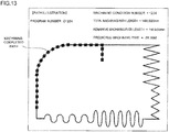
- Fig. 13 is a screen during the actual machining when the actual machining is started after the simulation illustrated in Fig. 12 and illustrates a machining-completed path so as to overlap a path according to the simulation.
- the remaining machining path length is decreased.
- the average machining speed is obtained from the machining-completed path length and the execution-completed machining time. Accordingly, the predicted machining time of the remaining machining path length is corrected.
- minute-radius arcs or acute-angle corner portions causing a decrease in machining speed are concentrated on the remaining machining path, it is considered that a larger error occurs in the predicted machining time of the remaining machining path length.
- the present invention is to provide a machining time prediction device capable of predicting a machining time of a wire discharge machining including a mixture of machining having different machining shapes at a good accuracy.
- a machining time prediction device predicting a time taken for machining by a wire discharge machining device based on a program, including: a predicted machining speed table where predicted machining speeds are registered in association with shape groups used for classification based on at least a shape of a machining path; a machining path generation unit generating machining path data including the machining path based on the program; a shape group determination unit determining which shape groups among the shape groups partial machining paths included in the machining path of the machining path data generated by the machining path generation unit belong to; a path length addition unit adding and summarizing path lengths of the partial machining paths for the respective shape groups on the basis of a result of determination by the shape group determination unit; a predicted machining time calculation unit calculating predicted machining times of the respective shape groups on the basis of the predicted machining speed table and the path lengths of the respective shape groups summarized by the path length addition unit; a predicted machining time summation unit calculating the predicted machining time of
- the shape group determination unit determines which shape groups among the shape groups machining-completed partial machining paths in actual machining by the wire discharge machining device based on the program belong to, wherein the machining time prediction device further includes: a machining-completed path length addition unit adding and summarizing the path lengths of the machining-completed partial machining paths for the respective shape groups on the basis of a result of determination by the shape group determination unit; an execution-completed machining time addition unit adding and summarizing execution-completed machining times for the respective shape groups on the basis of the result of determination by the shape group determination unit; a remaining path length calculation unit calculating remaining path lengths of the respective shape groups on the basis of the path lengths of all the partial machining paths of the respective shape groups summarized by the path length addition unit before the machining is started and the path lengths of the machining-completed partial machining paths of the respective shape groups summarized by the machining-completed path length addition unit; and an average machining speed calculation unit calculating average machining
- the average machining speed calculation unit updates the predicted machining speed registered in the predicted machining speed table on the basis of the calculated average machining speeds of the respective shape groups.
- Fig. 1 is a functional block diagram illustrating a machining time prediction device according to a first embodiment of the present invention.
- a machining time prediction device which predicts a machining time in simulation of automatic operation based on a machining program before the start of machining operation.
- the machining time prediction device 1 is configured to include a machining path generation unit 10, a shape group determination unit 11, a path length addition unit 12, a predicted machining time calculation unit 13, a predicted machining time summation unit 14, and a display unit 15.
- the machining path generation unit 10 reads a machining program 20 stored in a memory (not shown), sequentially performs analysis by performing simulation on the basis of the read machining program 20, and generates machining path data of wire discharge machining including machining path in the case of performing operation on the basis of the machining program 20 and information such as a taper angle obtained from a slope of a wire at the time of machining at positions on the machining path.
- the machining path generation unit 10 may be configured to sequentially generate the machining path data for each block included in the machining program 20.
- the shape group determination unit 11 performs shape group determination of determining which shape group each partial machining path of the machining paths of the machining path data which are generated by the machining path generation unit 10 belongs to.
- the shape groups are group classified on the basis of a shape, a taper angle, or the like of the machining path. In the wire discharge machining device, for example, between the case of machining a straight-line machining path and the case of machining a circular-arc machining path, the machining speed is different according to a control algorithm, a machining condition, or the like.
- the shape groups are used to classify partial machining paths which machining is to be performed at different machining speeds.
- classifications based on the specification (switching of an algorithm of a system program used for control or a machining condition) of the wire discharge machining device may be generated according to a change in machining speed for each partial machining path. Examples of the shape groups are illustrated in Fig. 2 . In the examples illustrated in Fig.
- a partial machining path of a shape where a machining path exhibits a straight line may be defined as a straight line portion
- a partial machining path of a shape where a machining path exhibits an arc may be defined as an arc portion
- a partial machining path where a machining path is bent at an acute angle of 90° or less may be defined as an acute-angle corner portion
- a partial machining path where a machining path exhibits a minute-radius circle may be defined as a minute-radius arc portion.
- the shape group determination unit 11 it is determined which shape group each partial machining path of the machining path included in the machining path data belongs to. For example, if attention is paid on only the shape, it is determined that the partial machining paths of the machining path illustrated in Fig. 12 belong to the respective shape groups illustrated below in Fig. 2 (actually, the partial machining paths may be further classified more in detail according to taper angles, arc radii, corner angles, or the like of the of the respective partial machining paths).
- the shape group determination unit 11 may set one block or two blocks of the machining program 20 analyzed by the machining path generation unit 10 as partial machining path and, after that, may determine the shape groups of the partial machining paths.
- the shape group determination unit may divides the machining path into partial machining paths and determine the shape groups of the partial machining paths on the basis of the specification (switching of an algorithm of a system program used for control or a machining condition) of the wire discharge machining device.
- the path length addition unit 12 adds and summarizes the path lengths of the partial machining paths of the machining path which is an object of determination by the shape group determination unit 11 for the respective shape groups.
- Fig. 3 illustrates an example where the path length addition unit 12 adds the path lengths of the partial machining paths constituting the machining path for the respective shape groups which the partial machining paths belong to.
- the predicted machining time calculation unit 13 calculates the predicted machining times of the respective shape groups to which the partial machining paths of the machining path as an object belong on the basis of the path lengths of the partial machining paths added and summarized for the respective shape groups by the path length addition unit 12, the predicted machining speed table 21 stored in advance in a memory (not shown), and the machining condition selected in the machining.
- Fig. 4 illustrates an example of the predicted machining speed table 21.
- predicted machining speeds of the respective shape groups having different machining speeds for respective machining conditions identified by numbers are registered in the predicted machining speed table 21.
- the predicted machining speeds of the respective shape groups registered in the predicted machining speed table 21 are registered by measuring average machining speeds of the respective shape groups in machining condition generation before shipment of a machine.
- predicted machining speeds of the respective shape groups with respect to each workpiece thickness may be registered. In this manner, by further adding the parameter, it is possible to further improve accuracy of the predicted machining time.
- the predicted machining time summation unit 14 calculates the predicted machining time of the total machining path length as an object of calculation by summing the predicted machining times of the respective shape groups which the respective partial machining paths of the machining paths as an object of calculation by the predicted machining time calculation unit 13 belong to.
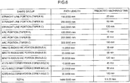
- Fig. 6 illustrates an example of the predicted machining times of the respective shape groups calculated by the predicted machining time calculation unit 13 and the predicted machining time of the total machining path length which is an object of calculation by the predicted machining time summation unit 14.
- the display unit 15 displays the predicted machining time of the total machining path length which is an object of the calculation by the predicted machining time summation unit 14 on a display (not shown) such as a liquid crystal display.
- the display unit 15 may display the predicted machining time together with the machining path as a result of simulation based on the machining program 20.
- the display unit may display the predicted machining times of the respective partial machining paths.
- Fig. 7 is a schematic flowchart illustrating processes executed in the machining time prediction device according to the embodiment.
- the machining path generation unit 10 performs simulation on the basis of a machining program 20 and generates machining path data of wire discharge machining including a machining path in the case of performing operation based on the machining program 20 and information such as a taper angle obtained from a slope of a wire in the machining at each position on the machining path.
- the shape group determination unit 11 determines shape groups of partial machining paths in units of one block or two blocks of the machining program 20.
- the path length addition unit 12 calculates path lengths of the respective shape groups by adding path lengths of the partial machining paths belonging to the shape group for the respective shape groups determined in step SA02.
- Step SA04 The predicted machining time calculation unit 13 calculates the predicted machining times of the respective shape groups on the basis of the path lengths of the respective shape groups calculated in step SA03, the predicted machining speed table 21, and the machining condition data.
- Step SA05 The predicted machining time summation unit 14 calculates the predicted machining time of the total machining path length generated in step SA01 by summing the predicted machining times of the respective shape groups calculated in the step SA04.
- Step SA06 The display unit 15 displays the predicted machining time of the total machining path length calculated in step SA05 on a display.
- highly-accurate machining time prediction can be performed based on a shape, a taper angle, or a machining condition of the machining path according to the machining program 20.
- the machining time prediction device 1 according to the embodiment may be mounted on a control device of the wire discharge machining device or on a simulation device of the wire discharge machining device. In addition, the machining time prediction device 1 according to the embodiment may be mounted on a PC.
- Fig. 8 is a functional block diagram illustrating a machining time prediction device according to a second embodiment of the present invention.
- a machining time prediction device which performs shape group determination on machining-completed paths and calculates machining-completed path lengths of shape groups and actual machining-completed machining times of the respective shapes during actual machining operation on a wire discharge machining device.
- the machining time prediction device 1 according to the embodiment is configured to be incorporated into a wire discharge machining device 2 including a machining path generation unit 10, an interpolation unit 30, a coordinate value updating unit 31, and a servo amp 32.
- the machining time prediction device 1 includes a shape group determination unit 11, a machining-completed path length addition unit 16, an execution-completed machining time addition unit 17, a remaining path length calculation unit 18, an average machining speed calculation unit 19, the predicted machining time calculation unit 13, a predicted machining time summation unit 14, and a display unit 15.
- the interpolation unit 30 In the wire discharge machining device 2, the interpolation unit 30 generates interpolation data indicating a moving amount of each motor of every interpolation period with respect to the machining path generated by the machining path generation unit 10 based on the machining program 20, the coordinate value updating unit 31 performs updating of coordinate values of each axis driven by each motor on the basis of the generated interpolation data to drive the servo amp 32, so that the motor of each component of the wire discharge machining device is controlled.
- the shape group determination unit 11 determines the shape groups of the respective partial machining paths of the machining path on the basis of the machining path generated by the machining path generation unit 10.
- the machining-completed path length addition unit 16 adds and summarizes of the path lengths of the machining-completed partial machining paths of the respective shape groups determined by the shape group determination unit 11.
- the execution-completed machining time addition unit 17 measures the actual machining times taken for the machining of the machining-completed partial machining paths and adds and summarizes the measured machining times as the execution-completed machining times for the respective shape groups of the partial machining paths.
- Fig. 9 illustrates an example of the machining-completed path lengths of the respective shape groups added and summarized by the machining-completed path length addition unit 16 and the execution-completed machining times of the respective shape groups added and summarized by the execution-completed machining time addition unit 17.
- the remaining path length calculation unit 18 calculates the remaining path lengths of the respective shape groups by subtracting the machining-completed path lengths of the respective shape groups calculated by the machining-completed path length addition unit 16 from the path lengths of the respective shape groups calculated by the configuration of the first embodiment before the machining is started.
- the average machining speed calculation unit 19 calculates the average machining speeds of the respective shape groups on the basis of the machining-completed path lengths of the respective shape groups added and summarized by the machining-completed path length addition unit 16 and the execution-completed machining times of the respective shape groups added to be summarized by the execution-completed machining time addition unit 17.
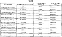
- Fig. 10 illustrates an example of the average machining speeds of the respective shape groups calculated by the average machining speed calculation unit 19.
- the average machining speed calculation unit 19 may update the predicted machining speeds of the respective shape groups stored in the predicted machining speed table 21 on the basis of the calculated average machining speeds of the respective shape groups.
- the predicted machining speeds of the respective shape groups stored in the predicted machining speed table 21 may be overwritten by the average machining speeds of the respective shape groups calculated by the average machining speed calculation unit 19, or in the case where the average machining speeds of the respective shape groups calculated by the average machining speed calculation unit 19 is more than or less than the predicted machining speeds of the respective shape groups stored in the predicted machining speed table 21, the predicted machining speeds of the respective shape groups stored in the predicted machining speed table 21 may be corrected according to an exceeding amount or a lacking amount.
- replacing with specified values of the predicted machining speeds of the respective shape groups in a memory and values considering the average machining speeds of the respective shape groups is effective means.
- the predicted machining time calculation unit 13 calculates the predicted machining time of the remaining machining paths of the respective shape group on the basis of the predicted machining speeds of the respective shape groups stored in the predicted machining speed table 21 and the remaining path lengths of the respective shape groups calculated by the remaining path length calculation unit 18.
- the predicted machining time summation unit 14 obtains the predicted machining time of the remaining machining path by summing the predicted machining times of the remaining machining paths of the respective shape groups calculated by the predicted machining time calculation unit 13.
- the display unit 15 displays the predicted machining time of the remaining machining path calculated by the predicted machining time summation unit 14 on a display (not shown) such as a liquid crystal display. As illustrated in Fig. 13 , the display unit 15 may display the predicted machining time of the remaining machining path together with display indicating the current machining situation. In addition, the display unit may display the predicted machining times of the remaining machining paths of the respective shape groups.
- Fig. 11 is a schematic flowchart illustrating processes executed in the machining time prediction device according to the embodiment.
- Step SB01 The machining path generation unit 10 sequentially reads blocks from the machining program 20 to perform analysis and generates machining path data on the basis of the read blocks.
- the interpolation unit 30 generates interpolation data in every interpolation period according to a machining speed on the basis of the machining path data, and the coordinate value updating unit 31 updates coordinate values of each axis on the basis of the interpolation data.
- Step SB03 The servo amp 32 outputs a move command to a motor according to the interpolation data to control the motor.
- the shape group determination unit 11 determines shape groups of partial machining paths in units of one block or two blocks of the machining program 20.
- Step SB05 The machining-completed path length addition unit 16 adds and summarizes the machining-completed path lengths of the respective shape groups.
- Step SB06 The execution-completed machining time addition unit 17 adds and summarizes the execution-completed machining times of the respective shape groups.
- the remaining path length calculation unit 18 calculates the remaining path lengths of the respective shape groups.
- the average machining speed calculation unit 19 calculates the average machining speeds of the respective shape groups on the basis of the machining-completed path lengths of the respective shape groups calculated in step SB05 and the execution-completed machining times of the respective shape groups calculated in step SB06 and updates the predicted machining speeds of the respective shape groups registered in the predicted machining speed table 21.
- Step SB09 The predicted machining time calculation unit 13 calculates the predicted machining times of the remaining machining paths of the respective shape groups on the basis of the remaining path lengths of the respective shape groups calculated in step SB07, the predicted machining speed table 21, and the machining condition data.
- Step SB10 The predicted machining time summation unit 14 calculates the predicted machining time of the remaining machining path by summing the predicted machining times of the remaining machining paths of the respective shape groups calculated in step SB09.
- Step SB11 The display unit 15 displays the predicted machining time of the remaining machining path calculated in step SB10 on a display.
- Step SB12 It is determined whether or not machining based on the machining program is ended. In the case where the machining based on the machining program is ended, the process is ended, and in the case where the machining is not ended, the process proceeds to step SB01.
- machining time prediction device 1 In the machining time prediction device 1 according to the embodiment described above, after the machining based on the machining program 20 is started, during the machining, highly-accurate remaining machining time prediction can be performed on the basis of a shape, a taper angle, a machining condition, or the like of the machining path by the machining program 20.
Landscapes
- Engineering & Computer Science (AREA)
- Automation & Control Theory (AREA)
- General Physics & Mathematics (AREA)
- Physics & Mathematics (AREA)
- Human Computer Interaction (AREA)
- Manufacturing & Machinery (AREA)
- Electrochemistry (AREA)
- Mechanical Engineering (AREA)
- Chemical Kinetics & Catalysis (AREA)
- Chemical & Material Sciences (AREA)
- Health & Medical Sciences (AREA)
- Artificial Intelligence (AREA)
- Computer Vision & Pattern Recognition (AREA)
- Evolutionary Computation (AREA)
- Medical Informatics (AREA)
- Software Systems (AREA)
- Electrical Discharge Machining, Electrochemical Machining, And Combined Machining (AREA)
- Numerical Control (AREA)
- Management, Administration, Business Operations System, And Electronic Commerce (AREA)
Abstract
Description
- The present invention relates to a machining time prediction device, and more particularly, to a machining time prediction device in wire discharge machining.
- Since wire discharge machining requires a very long machining time, in many case, the wire discharge machining is performed in an unattended manner. Therefore, in some cases, a machining end time is unclear, and after the machining is ended, a workpiece is left along, the workpiece is rusted. In addition, since the machining time is long, a predicted machining time is information necessary for estimating work cost.
- In order to solve the above-described problems, for example,
JP 06-320344 A JP 03-111125 A - However, in the wire discharge machining, the machining speeds are greatly different according to a difference in workpiece thickness or machining shape such as a taper, an acute corner, or a minute-radius arc. For this reason, if only one predicted machining speed based on a machining condition is prepared, it is difficult to obtain predicted machining times of various machining paths at a good accuracy.
- In addition, in the case of the method of obtaining the average machining speed from the machining-completed path length and the execution-completed machining time during the actual machining and correcting the predicted machining time of the remaining machining path by using the value, with respect to machining where a large number of shapes having high machining speeds exist in the first half of the machining and a large number of shape having low machining speeds exist in the second half of the machining, there occurs a large error in the corrected predicted machining time of the remaining machining path.
-
Fig. 12 is a screen of simulation of automatic operation performed in a wire discharge machining device and illustrates a machining program path, a selected machining condition number, a total machining path length and a remaining machining path length calculated through simulation, and a predicted machining time calculated from a predicted machining speed according to the selected machining condition. Before the actual machining is started, the remaining machining path length is set to have the same as that of the total machining path length. -
Fig. 13 is a screen during the actual machining when the actual machining is started after the simulation illustrated inFig. 12 and illustrates a machining-completed path so as to overlap a path according to the simulation. In the screen ofFig. 13 , as the actual machining progresses, the remaining machining path length is decreased. The average machining speed is obtained from the machining-completed path length and the execution-completed machining time. Accordingly, the predicted machining time of the remaining machining path length is corrected. However, in the machining path illustrated inFig. 13 , since minute-radius arcs or acute-angle corner portions causing a decrease in machining speed are concentrated on the remaining machining path, it is considered that a larger error occurs in the predicted machining time of the remaining machining path length. - As described above, in the method of calculating the predicted machining time in the related art, since the accuracy is low, there is a problem in that it is difficult to apply the method to manage machining plan or estimate work cost.
- The present invention is to provide a machining time prediction device capable of predicting a machining time of a wire discharge machining including a mixture of machining having different machining shapes at a good accuracy.
- According to an aspect of the present invention, there is provided a machining time prediction device predicting a time taken for machining by a wire discharge machining device based on a program, including: a predicted machining speed table where predicted machining speeds are registered in association with shape groups used for classification based on at least a shape of a machining path; a machining path generation unit generating machining path data including the machining path based on the program; a shape group determination unit determining which shape groups among the shape groups partial machining paths included in the machining path of the machining path data generated by the machining path generation unit belong to; a path length addition unit adding and summarizing path lengths of the partial machining paths for the respective shape groups on the basis of a result of determination by the shape group determination unit; a predicted machining time calculation unit calculating predicted machining times of the respective shape groups on the basis of the predicted machining speed table and the path lengths of the respective shape groups summarized by the path length addition unit; a predicted machining time summation unit calculating the predicted machining time of the machining path by summing the predicted machining times of the respective shape groups calculated by the predicted machining time calculation unit; and a display unit displaying the predicted machining time of the machining path calculated by the predicted machining time summation unit.
- In the machining time prediction device, the shape group determination unit determines which shape groups among the shape groups machining-completed partial machining paths in actual machining by the wire discharge machining device based on the program belong to, wherein the machining time prediction device further includes: a machining-completed path length addition unit adding and summarizing the path lengths of the machining-completed partial machining paths for the respective shape groups on the basis of a result of determination by the shape group determination unit; an execution-completed machining time addition unit adding and summarizing execution-completed machining times for the respective shape groups on the basis of the result of determination by the shape group determination unit; a remaining path length calculation unit calculating remaining path lengths of the respective shape groups on the basis of the path lengths of all the partial machining paths of the respective shape groups summarized by the path length addition unit before the machining is started and the path lengths of the machining-completed partial machining paths of the respective shape groups summarized by the machining-completed path length addition unit; and an average machining speed calculation unit calculating average machining speeds of the respective shape groups on the basis of the path lengths of the machining-completed partial machining paths of the respective shape groups summarized by the machining-completed path length addition unit and the execution-completed machining times of the respective shape groups summarized by the execution-completed machining time addition unit, wherein the predicted machining time calculation unit calculates the predicted machining times of the remaining machining paths of the respective shape groups on the basis of the average machining speeds of the respective shape groups calculated by the average machining speed calculation unit and the remaining path lengths of the respective shape groups calculated by the remaining path length calculation unit, wherein the predicted machining time summation unit calculates a predicted machining time of a remaining machining path of the machining by summing the predicted machining times of the respective shape groups calculated by the predicted machining time calculation unit, and wherein the display unit displays the predicted machining time of the remaining machining path of the machining calculated by the predicted machining time summation unit.
- In the machining time prediction device, the average machining speed calculation unit updates the predicted machining speed registered in the predicted machining speed table on the basis of the calculated average machining speeds of the respective shape groups.
- According to the present invention, since a highly-accurate predicted machining time which is not affected by a machining shape can be acquired, it is possible to easily manage machining plan or estimate work cost.
- The foregoing and other objects and features of the present invention will be apparent from the description of the following embodiments with reference to the attached drawings of figures:
-
Fig. 1 is a functional block diagram illustrating a machining time prediction device according to a first embodiment of the present invention; -
Fig. 2 is a diagram illustrating shape groups in the present invention; -
Fig. 3 is a diagram illustrating examples of path lengths for shape groups; -
Fig. 4 is a diagram illustrating examples of predicted machining speed tables; -
Fig. 5 is a diagram illustrating an example of a predicted machining speed table added with workpiece thickness; -
Fig. 6 is a diagram illustrating examples of path lengths and predicted machining times; -
Fig. 7 is a schematic flowchart illustrating processes executed in the machining time prediction device ofFig. 1 ; -
Fig. 8 is a functional block diagram illustrating a machining time prediction device according to a second embodiment of the present invention; -
Fig. 9 is a diagram illustrating examples of machining-completed path lengths and execution-completed machining times; -
Fig. 10 is a diagram illustrating examples of average machining speeds of shape groups; -
Fig. 11 is a schematic flowchart illustrating processes executed in the machining time prediction device ofFig. 8 ; -
Fig. 12 is a diagram illustrating an example of a screen display when simulation of automatic operation in a wire discharge machining device is performed; and -
Fig. 13 is a diagram illustrating an example of a screen display during the actual machining when actual machining is started after the simulation illustrated inFig. 12 . - Hereinafter, embodiments of the present invention will be described with reference to the drawings.
-
Fig. 1 is a functional block diagram illustrating a machining time prediction device according to a first embodiment of the present invention. In the embodiment, considered is a machining time prediction device which predicts a machining time in simulation of automatic operation based on a machining program before the start of machining operation. The machiningtime prediction device 1 is configured to include a machiningpath generation unit 10, a shapegroup determination unit 11, a pathlength addition unit 12, a predicted machiningtime calculation unit 13, a predicted machiningtime summation unit 14, and adisplay unit 15. - The machining
path generation unit 10 reads amachining program 20 stored in a memory (not shown), sequentially performs analysis by performing simulation on the basis of the readmachining program 20, and generates machining path data of wire discharge machining including machining path in the case of performing operation on the basis of themachining program 20 and information such as a taper angle obtained from a slope of a wire at the time of machining at positions on the machining path. The machiningpath generation unit 10 may be configured to sequentially generate the machining path data for each block included in themachining program 20. - The shape
group determination unit 11 performs shape group determination of determining which shape group each partial machining path of the machining paths of the machining path data which are generated by the machiningpath generation unit 10 belongs to. The shape groups are group classified on the basis of a shape, a taper angle, or the like of the machining path. In the wire discharge machining device, for example, between the case of machining a straight-line machining path and the case of machining a circular-arc machining path, the machining speed is different according to a control algorithm, a machining condition, or the like. The shape groups are used to classify partial machining paths which machining is to be performed at different machining speeds. In the classification of the shape groups, classifications based on the specification (switching of an algorithm of a system program used for control or a machining condition) of the wire discharge machining device may be generated according to a change in machining speed for each partial machining path. Examples of the shape groups are illustrated inFig. 2 . In the examples illustrated inFig. 2 , a partial machining path of a shape where a machining path exhibits a straight line may be defined as a straight line portion, a partial machining path of a shape where a machining path exhibits an arc may be defined as an arc portion, a partial machining path where a machining path is bent at an acute angle of 90° or less may be defined as an acute-angle corner portion, and a partial machining path where a machining path exhibits a minute-radius circle may be defined as a minute-radius arc portion. These shape groups may be further classified in detail according to a taper angle, an arc radius, a corner angle, or the like. - In the shape group determination performed by the shape
group determination unit 11, it is determined which shape group each partial machining path of the machining path included in the machining path data belongs to. For example, if attention is paid on only the shape, it is determined that the partial machining paths of the machining path illustrated inFig. 12 belong to the respective shape groups illustrated below inFig. 2 (actually, the partial machining paths may be further classified more in detail according to taper angles, arc radii, corner angles, or the like of the of the respective partial machining paths). The shapegroup determination unit 11 may set one block or two blocks of themachining program 20 analyzed by the machiningpath generation unit 10 as partial machining path and, after that, may determine the shape groups of the partial machining paths. In addition, as described above, the shape group determination unit may divides the machining path into partial machining paths and determine the shape groups of the partial machining paths on the basis of the specification (switching of an algorithm of a system program used for control or a machining condition) of the wire discharge machining device. - The path
length addition unit 12 adds and summarizes the path lengths of the partial machining paths of the machining path which is an object of determination by the shapegroup determination unit 11 for the respective shape groups.Fig. 3 illustrates an example where the pathlength addition unit 12 adds the path lengths of the partial machining paths constituting the machining path for the respective shape groups which the partial machining paths belong to. - The predicted machining
time calculation unit 13 calculates the predicted machining times of the respective shape groups to which the partial machining paths of the machining path as an object belong on the basis of the path lengths of the partial machining paths added and summarized for the respective shape groups by the pathlength addition unit 12, the predicted machining speed table 21 stored in advance in a memory (not shown), and the machining condition selected in the machining. -
Fig. 4 illustrates an example of the predicted machining speed table 21. As illustrated inFig. 4 , in the predicted machining speed table 21, predicted machining speeds of the respective shape groups having different machining speeds for respective machining conditions identified by numbers are registered. The predicted machining speeds of the respective shape groups registered in the predicted machining speed table 21 are registered by measuring average machining speeds of the respective shape groups in machining condition generation before shipment of a machine. As illustrated inFig. 5 , in the predicted machining speed table 21, in addition to the condition such as workpiece thickness affecting the machining speed, predicted machining speeds of the respective shape groups with respect to each workpiece thickness may be registered. In this manner, by further adding the parameter, it is possible to further improve accuracy of the predicted machining time. - The predicted machining
time summation unit 14 calculates the predicted machining time of the total machining path length as an object of calculation by summing the predicted machining times of the respective shape groups which the respective partial machining paths of the machining paths as an object of calculation by the predicted machiningtime calculation unit 13 belong to. -
Fig. 6 illustrates an example of the predicted machining times of the respective shape groups calculated by the predicted machiningtime calculation unit 13 and the predicted machining time of the total machining path length which is an object of calculation by the predicted machiningtime summation unit 14. - The
display unit 15 displays the predicted machining time of the total machining path length which is an object of the calculation by the predicted machiningtime summation unit 14 on a display (not shown) such as a liquid crystal display. Thedisplay unit 15 may display the predicted machining time together with the machining path as a result of simulation based on themachining program 20. In addition, the display unit may display the predicted machining times of the respective partial machining paths. -
Fig. 7 is a schematic flowchart illustrating processes executed in the machining time prediction device according to the embodiment. - [Step SA01] The machining
path generation unit 10 performs simulation on the basis of amachining program 20 and generates machining path data of wire discharge machining including a machining path in the case of performing operation based on themachining program 20 and information such as a taper angle obtained from a slope of a wire in the machining at each position on the machining path. - [Step SA02] The shape
group determination unit 11 determines shape groups of partial machining paths in units of one block or two blocks of themachining program 20. - [Step SA03] The path
length addition unit 12 calculates path lengths of the respective shape groups by adding path lengths of the partial machining paths belonging to the shape group for the respective shape groups determined in step SA02. - [Step SA04] The predicted machining
time calculation unit 13 calculates the predicted machining times of the respective shape groups on the basis of the path lengths of the respective shape groups calculated in step SA03, the predicted machining speed table 21, and the machining condition data. - [Step SA05] The predicted machining
time summation unit 14 calculates the predicted machining time of the total machining path length generated in step SA01 by summing the predicted machining times of the respective shape groups calculated in the step SA04. - [Step SA06] The
display unit 15 displays the predicted machining time of the total machining path length calculated in step SA05 on a display. - In the machining
time prediction device 1 according to the above-described embodiment, before the machining based on themachining program 20 is started, highly-accurate machining time prediction can be performed based on a shape, a taper angle, or a machining condition of the machining path according to themachining program 20. - The machining
time prediction device 1 according to the embodiment may be mounted on a control device of the wire discharge machining device or on a simulation device of the wire discharge machining device. In addition, the machiningtime prediction device 1 according to the embodiment may be mounted on a PC. -
Fig. 8 is a functional block diagram illustrating a machining time prediction device according to a second embodiment of the present invention. In the embodiment, considered is a machining time prediction device which performs shape group determination on machining-completed paths and calculates machining-completed path lengths of shape groups and actual machining-completed machining times of the respective shapes during actual machining operation on a wire discharge machining device. The machiningtime prediction device 1 according to the embodiment is configured to be incorporated into a wiredischarge machining device 2 including a machiningpath generation unit 10, aninterpolation unit 30, a coordinatevalue updating unit 31, and aservo amp 32. Therefore, the machiningtime prediction device 1 includes a shapegroup determination unit 11, a machining-completed pathlength addition unit 16, an execution-completed machiningtime addition unit 17, a remaining pathlength calculation unit 18, an average machiningspeed calculation unit 19, the predicted machiningtime calculation unit 13, a predicted machiningtime summation unit 14, and adisplay unit 15. - In the wire
discharge machining device 2, theinterpolation unit 30 generates interpolation data indicating a moving amount of each motor of every interpolation period with respect to the machining path generated by the machiningpath generation unit 10 based on themachining program 20, the coordinatevalue updating unit 31 performs updating of coordinate values of each axis driven by each motor on the basis of the generated interpolation data to drive theservo amp 32, so that the motor of each component of the wire discharge machining device is controlled. - Similarly to the first embodiment, the shape
group determination unit 11 determines the shape groups of the respective partial machining paths of the machining path on the basis of the machining path generated by the machiningpath generation unit 10. - The machining-completed path
length addition unit 16 adds and summarizes of the path lengths of the machining-completed partial machining paths of the respective shape groups determined by the shapegroup determination unit 11. - The execution-completed machining
time addition unit 17 measures the actual machining times taken for the machining of the machining-completed partial machining paths and adds and summarizes the measured machining times as the execution-completed machining times for the respective shape groups of the partial machining paths. -
Fig. 9 illustrates an example of the machining-completed path lengths of the respective shape groups added and summarized by the machining-completed pathlength addition unit 16 and the execution-completed machining times of the respective shape groups added and summarized by the execution-completed machiningtime addition unit 17. - The remaining path
length calculation unit 18 calculates the remaining path lengths of the respective shape groups by subtracting the machining-completed path lengths of the respective shape groups calculated by the machining-completed pathlength addition unit 16 from the path lengths of the respective shape groups calculated by the configuration of the first embodiment before the machining is started. - The average machining
speed calculation unit 19 calculates the average machining speeds of the respective shape groups on the basis of the machining-completed path lengths of the respective shape groups added and summarized by the machining-completed pathlength addition unit 16 and the execution-completed machining times of the respective shape groups added to be summarized by the execution-completed machiningtime addition unit 17.Fig. 10 illustrates an example of the average machining speeds of the respective shape groups calculated by the average machiningspeed calculation unit 19. - The average machining
speed calculation unit 19 may update the predicted machining speeds of the respective shape groups stored in the predicted machining speed table 21 on the basis of the calculated average machining speeds of the respective shape groups. As an updating method, the predicted machining speeds of the respective shape groups stored in the predicted machining speed table 21 may be overwritten by the average machining speeds of the respective shape groups calculated by the average machiningspeed calculation unit 19, or in the case where the average machining speeds of the respective shape groups calculated by the average machiningspeed calculation unit 19 is more than or less than the predicted machining speeds of the respective shape groups stored in the predicted machining speed table 21, the predicted machining speeds of the respective shape groups stored in the predicted machining speed table 21 may be corrected according to an exceeding amount or a lacking amount. In addition, replacing with specified values of the predicted machining speeds of the respective shape groups in a memory and values considering the average machining speeds of the respective shape groups is effective means. - The predicted machining
time calculation unit 13 calculates the predicted machining time of the remaining machining paths of the respective shape group on the basis of the predicted machining speeds of the respective shape groups stored in the predicted machining speed table 21 and the remaining path lengths of the respective shape groups calculated by the remaining pathlength calculation unit 18. - The predicted machining
time summation unit 14 obtains the predicted machining time of the remaining machining path by summing the predicted machining times of the remaining machining paths of the respective shape groups calculated by the predicted machiningtime calculation unit 13. - Next, the
display unit 15 displays the predicted machining time of the remaining machining path calculated by the predicted machiningtime summation unit 14 on a display (not shown) such as a liquid crystal display. As illustrated inFig. 13 , thedisplay unit 15 may display the predicted machining time of the remaining machining path together with display indicating the current machining situation. In addition, the display unit may display the predicted machining times of the remaining machining paths of the respective shape groups. -
Fig. 11 is a schematic flowchart illustrating processes executed in the machining time prediction device according to the embodiment. - [Step SB01] The machining
path generation unit 10 sequentially reads blocks from themachining program 20 to perform analysis and generates machining path data on the basis of the read blocks. - [Step SB02] The
interpolation unit 30 generates interpolation data in every interpolation period according to a machining speed on the basis of the machining path data, and the coordinatevalue updating unit 31 updates coordinate values of each axis on the basis of the interpolation data. - [Step SB03] The
servo amp 32 outputs a move command to a motor according to the interpolation data to control the motor. - [Step SB04] The shape
group determination unit 11 determines shape groups of partial machining paths in units of one block or two blocks of themachining program 20. - [Step SB05] The machining-completed path
length addition unit 16 adds and summarizes the machining-completed path lengths of the respective shape groups. - [Step SB06] The execution-completed machining
time addition unit 17 adds and summarizes the execution-completed machining times of the respective shape groups. - [Step SB07] The remaining path
length calculation unit 18 calculates the remaining path lengths of the respective shape groups. - [Step SB08] The average machining
speed calculation unit 19 calculates the average machining speeds of the respective shape groups on the basis of the machining-completed path lengths of the respective shape groups calculated in step SB05 and the execution-completed machining times of the respective shape groups calculated in step SB06 and updates the predicted machining speeds of the respective shape groups registered in the predicted machining speed table 21. - [Step SB09] The predicted machining
time calculation unit 13 calculates the predicted machining times of the remaining machining paths of the respective shape groups on the basis of the remaining path lengths of the respective shape groups calculated in step SB07, the predicted machining speed table 21, and the machining condition data. - [Step SB10] The predicted machining
time summation unit 14 calculates the predicted machining time of the remaining machining path by summing the predicted machining times of the remaining machining paths of the respective shape groups calculated in step SB09. - [Step SB11] The
display unit 15 displays the predicted machining time of the remaining machining path calculated in step SB10 on a display. - [Step SB12] It is determined whether or not machining based on the machining program is ended. In the case where the machining based on the machining program is ended, the process is ended, and in the case where the machining is not ended, the process proceeds to step SB01.
- In the machining
time prediction device 1 according to the embodiment described above, after the machining based on themachining program 20 is started, during the machining, highly-accurate remaining machining time prediction can be performed on the basis of a shape, a taper angle, a machining condition, or the like of the machining path by themachining program 20. - Heretofore, although the embodiments of the present invention are described, the present invention is not limited to the above-described embodiments, various aspects can be embodied through various modifications.
Claims (3)
- A machining time prediction device predicting a time taken for machining by a wire discharge machining device based on a program, comprising:a predicted machining speed table where predicted machining speeds are registered in association with shape groups used for classification based on at least a shape of a machining path;a machining path generation unit generating machining path data including the machining path based on the program;a shape group determination unit determining which shape groups among the shape groups partial machining paths included in the machining path of the machining path data generated by the machining path generation unit belong to;a path length addition unit adding and summarizing path lengths of the partial machining paths for the respective shape groups on the basis of a result of determination by the shape group determination unit;a predicted machining time calculation unit calculating predicted machining times of the respective shape groups on the basis of the predicted machining speed table and the path lengths of the respective shape groups summarized by the path length addition unit;a predicted machining time summation unit calculating the predicted machining time of the machining path by summing the predicted machining times of the respective shape groups calculated by the predicted machining time calculation unit; anda display unit displaying the predicted machining time of the machining path calculated by the predicted machining time summation unit.
- The machining time prediction device according to claim 1,
wherein the shape group determination unit determines which shape groups among the shape groups machining-completed partial machining paths in actual machining by the wire discharge machining device based on the program belong to,
wherein the machining time prediction device further comprises:a machining-completed path length addition unit adding and summarizing the path lengths of the machining-completed partial machining paths for the respective shape groups on the basis of a result of determination by the shape group determination unit;an execution-completed machining time addition unit adding and summarizing execution-completed machining times for the respective shape groups on the basis of the result of determination by the shape group determination unit;a remaining path length calculation unit calculating remaining path lengths of the respective shape groups on the basis of the path lengths of all the partial machining paths of the respective shape groups summarized by the path length addition unit before the machining is started and the path lengths of the machining-completed partial machining paths of the respective shape groups summarized by the machining-completed path length addition unit; andan average machining speed calculation unit calculating average machining speeds of the respective shape groups on the basis of the path lengths of the machining-completed partial machining paths of the respective shape groups summarized by the machining-completed path length addition unit and the execution-completed machining times of the respective shape groups summarized by the execution-completed machining time addition unit,wherein the predicted machining time calculation unit calculates the predicted machining times of the remaining machining paths of the respective shape groups on the basis of the average machining speeds of the respective shape groups calculated by the average machining speed calculation unit and the remaining path lengths of the respective shape groups calculated by the remaining path length calculation unit,wherein the predicted machining time summation unit calculates a predicted machining time of a remaining machining path of the machining by summing the predicted machining times of the respective shape groups calculated by the predicted machining time calculation unit, andwherein the display unit displays the predicted machining time of the remaining machining path of the machining calculated by the predicted machining time summation unit. - The machining time prediction device according to claim 2, wherein the average machining speed calculation unit updates the predicted machining speed registered in the predicted machining speed table on the basis of the calculated average machining speeds of the respective shape groups.
Applications Claiming Priority (1)
| Application Number | Priority Date | Filing Date | Title |
|---|---|---|---|
| JP2016008244A JP6276299B2 (en) | 2016-01-19 | 2016-01-19 | Machining time prediction device in wire electrical discharge machining |
Publications (3)
| Publication Number | Publication Date |
|---|---|
| EP3196722A2 true EP3196722A2 (en) | 2017-07-26 |
| EP3196722A3 EP3196722A3 (en) | 2017-08-09 |
| EP3196722B1 EP3196722B1 (en) | 2020-11-11 |
Family
ID=57838289
Family Applications (1)
| Application Number | Title | Priority Date | Filing Date |
|---|---|---|---|
| EP17151999.4A Active EP3196722B1 (en) | 2016-01-19 | 2017-01-18 | Machining time prediction device |
Country Status (4)
| Country | Link |
|---|---|
| US (1) | US10303129B2 (en) |
| EP (1) | EP3196722B1 (en) |
| JP (1) | JP6276299B2 (en) |
| CN (1) | CN106975809B (en) |
Families Citing this family (5)
| Publication number | Priority date | Publication date | Assignee | Title |
|---|---|---|---|---|
| JP6871207B2 (en) * | 2018-09-05 | 2021-05-12 | ファナック株式会社 | Machining time predictor |
| FR3097458B1 (en) * | 2019-06-24 | 2021-06-11 | Stelia Aerospace | Method of machining a metal panel by an automated mechanical machining system |
| CN110666261B (en) * | 2019-09-17 | 2020-10-20 | 深圳模德宝科技有限公司 | Method and device for calculating electrode discharge time of numerical control equipment |
| CN113791579B (en) * | 2021-09-17 | 2023-11-03 | 深圳模德宝科技有限公司 | Wire cutting machining time prediction method, device, computer equipment and storage medium |
| JP7695410B2 (en) | 2022-01-28 | 2025-06-18 | ファナック株式会社 | Wire electric discharge machine, control device, and control method |
Citations (2)
| Publication number | Priority date | Publication date | Assignee | Title |
|---|---|---|---|---|
| JPH03111125A (en) | 1989-09-27 | 1991-05-10 | Mitsubishi Electric Corp | Machining hour predicting method for wire electric discharge machine |
| JPH06320344A (en) | 1993-05-10 | 1994-11-22 | Fanuc Ltd | Electric discharge machining device |
Family Cites Families (15)
| Publication number | Priority date | Publication date | Assignee | Title |
|---|---|---|---|---|
| JPS6339730A (en) * | 1986-08-04 | 1988-02-20 | Amada Co Ltd | Control method for machining feed speed of wire-cut electric spark machine |
| JPH02100822A (en) | 1988-10-04 | 1990-04-12 | Mitsubishi Electric Corp | Estimating device for working time of electric discharge machining |
| JPH045316U (en) * | 1990-04-26 | 1992-01-17 | ||
| JPH0430914A (en) * | 1990-05-23 | 1992-02-03 | Amada Washino Co Ltd | Method and device for editing program data for wire-cut electric discharge machine |
| JPH0651821A (en) * | 1992-01-10 | 1994-02-25 | Nec Corp | Method and device for predicting work time of nc work machine |
| JPH07256518A (en) * | 1994-03-18 | 1995-10-09 | Fujitsu Ltd | Wire electrical discharge machining method |
| DE19882992T1 (en) | 1998-05-12 | 2001-09-27 | Mitsubishi Electric Corp | Numerically controlling device for a processing tool |
| JP2001157923A (en) | 1999-11-29 | 2001-06-12 | Makino Milling Mach Co Ltd | Method and apparatus for controlling wire electric discharge machine |
| JP2003175439A (en) | 2001-12-11 | 2003-06-24 | Mori Seiki Co Ltd | Estimation device for machining time of NC machine tool |
| CN100343005C (en) * | 2003-05-20 | 2007-10-17 | 三菱电机株式会社 | EDM |
| JP4891528B2 (en) | 2004-04-07 | 2012-03-07 | オークマ株式会社 | Machining time calculation device |
| JP2006305689A (en) | 2005-04-28 | 2006-11-09 | Makino Milling Mach Co Ltd | Wire electrical discharge machine with machining cost calculation function |
| JP5595559B1 (en) | 2013-06-19 | 2014-09-24 | 株式会社牧野フライス製作所 | Electric discharge machine |
| JP5815663B2 (en) | 2013-12-26 | 2015-11-17 | ファナック株式会社 | Machining path generator for keyway machining for wire electric discharge machine |
| CN104698982B (en) | 2015-03-13 | 2018-01-12 | 江俊逢 | Stepping type CNC system and the generation method of processed file, real-time control method |
-
2016
- 2016-01-19 JP JP2016008244A patent/JP6276299B2/en active Active
-
2017
- 2017-01-18 CN CN201710034385.7A patent/CN106975809B/en active Active
- 2017-01-18 US US15/409,109 patent/US10303129B2/en active Active
- 2017-01-18 EP EP17151999.4A patent/EP3196722B1/en active Active
Patent Citations (2)
| Publication number | Priority date | Publication date | Assignee | Title |
|---|---|---|---|---|
| JPH03111125A (en) | 1989-09-27 | 1991-05-10 | Mitsubishi Electric Corp | Machining hour predicting method for wire electric discharge machine |
| JPH06320344A (en) | 1993-05-10 | 1994-11-22 | Fanuc Ltd | Electric discharge machining device |
Also Published As
| Publication number | Publication date |
|---|---|
| CN106975809A (en) | 2017-07-25 |
| US10303129B2 (en) | 2019-05-28 |
| JP2017127918A (en) | 2017-07-27 |
| US20170205779A1 (en) | 2017-07-20 |
| CN106975809B (en) | 2019-05-21 |
| EP3196722B1 (en) | 2020-11-11 |
| EP3196722A3 (en) | 2017-08-09 |
| JP6276299B2 (en) | 2018-02-07 |
Similar Documents
| Publication | Publication Date | Title |
|---|---|---|
| EP3196722B1 (en) | Machining time prediction device | |
| CN109581962B (en) | Numerical control system | |
| JP5149421B2 (en) | Numerical control device having machining time prediction unit and machining error prediction unit | |
| CN104062941B (en) | Machining condition display device | |
| US8829383B2 (en) | Wire electric discharge machine and wire electric discharge machining method | |
| CN101284322B (en) | Controller for wire-cut electrical discharge machines | |
| JP5715217B2 (en) | Numerical control device with program prefetching function | |
| EP3048500B1 (en) | Numerical controller equipped with drawing path correction function | |
| EP2639003B1 (en) | Wire electric discharge machine controller for correcting machining route using program commands | |
| CN107340754B (en) | Numerical controller | |
| JP5624163B2 (en) | Numerical control device with function to rework threading cycle | |
| JP6312725B2 (en) | Numerical control device with taper angle correction function in taper machining in skiving | |
| JP2014054700A (en) | Thermal displacement correction unit for machine tool | |
| EP2642361A2 (en) | Machining state information displaying device | |
| CN107037781B (en) | Machining time prediction device | |
| CN105302544A (en) | Machining time estimating device for estimating machining time after modification of nc program | |
| CN105446270B (en) | The control device of lathe | |
| EP3015208A1 (en) | Keyway machining path creating device for wire electric discharge machine | |
| CN105312695A (en) | Wire electric discharge machine having erroneous machining preventing function | |
| JP6321605B2 (en) | Numerical control device for speed control by curvature and curvature variation | |
| CN102629119B (en) | Numerical controller that confirms the completion of positioning of the rotary axis | |
| JP7372191B2 (en) | Program editing device, wire electrical discharge machine and program editing method | |
| CN104281445B (en) | Can designated program perform step movement controller | |
| CN103801775B (en) | The control device of wire cutting machine, wire cutting machine and wire cutting method | |
| JP2017049766A (en) | Numerical control device with maximum speed control function by position |
Legal Events
| Date | Code | Title | Description |
|---|---|---|---|
| PUAI | Public reference made under article 153(3) epc to a published international application that has entered the european phase |
Free format text: ORIGINAL CODE: 0009012 |
|
| STAA | Information on the status of an ep patent application or granted ep patent |
Free format text: STATUS: THE APPLICATION HAS BEEN PUBLISHED |
|
| PUAL | Search report despatched |
Free format text: ORIGINAL CODE: 0009013 |
|
| AK | Designated contracting states |
Kind code of ref document: A2 Designated state(s): AL AT BE BG CH CY CZ DE DK EE ES FI FR GB GR HR HU IE IS IT LI LT LU LV MC MK MT NL NO PL PT RO RS SE SI SK SM TR |
|
| AX | Request for extension of the european patent |
Extension state: BA ME |
|
| AK | Designated contracting states |
Kind code of ref document: A3 Designated state(s): AL AT BE BG CH CY CZ DE DK EE ES FI FR GB GR HR HU IE IS IT LI LT LU LV MC MK MT NL NO PL PT RO RS SE SI SK SM TR |
|
| AX | Request for extension of the european patent |
Extension state: BA ME |
|
| RIC1 | Information provided on ipc code assigned before grant |
Ipc: B23H 7/20 20060101ALI20170704BHEP Ipc: G05B 19/4069 20060101AFI20170704BHEP Ipc: B23H 7/02 20060101ALI20170704BHEP |
|
| STAA | Information on the status of an ep patent application or granted ep patent |
Free format text: STATUS: REQUEST FOR EXAMINATION WAS MADE |
|
| 17P | Request for examination filed |
Effective date: 20180125 |
|
| RBV | Designated contracting states (corrected) |
Designated state(s): AL AT BE BG CH CY CZ DE DK EE ES FI FR GB GR HR HU IE IS IT LI LT LU LV MC MK MT NL NO PL PT RO RS SE SI SK SM TR |
|
| GRAP | Despatch of communication of intention to grant a patent |
Free format text: ORIGINAL CODE: EPIDOSNIGR1 |
|
| STAA | Information on the status of an ep patent application or granted ep patent |
Free format text: STATUS: GRANT OF PATENT IS INTENDED |
|
| INTG | Intention to grant announced |
Effective date: 20200603 |
|
| GRAS | Grant fee paid |
Free format text: ORIGINAL CODE: EPIDOSNIGR3 |
|
| GRAA | (expected) grant |
Free format text: ORIGINAL CODE: 0009210 |
|
| STAA | Information on the status of an ep patent application or granted ep patent |
Free format text: STATUS: THE PATENT HAS BEEN GRANTED |
|
| AK | Designated contracting states |
Kind code of ref document: B1 Designated state(s): AL AT BE BG CH CY CZ DE DK EE ES FI FR GB GR HR HU IE IS IT LI LT LU LV MC MK MT NL NO PL PT RO RS SE SI SK SM TR |
|
| REG | Reference to a national code |
Ref country code: GB Ref legal event code: FG4D |
|
| REG | Reference to a national code |
Ref country code: CH Ref legal event code: NV Representative=s name: DR. LUSUARDI AG, CH Ref country code: CH Ref legal event code: EP |
|
| REG | Reference to a national code |
Ref country code: AT Ref legal event code: REF Ref document number: 1334092 Country of ref document: AT Kind code of ref document: T Effective date: 20201115 |
|
| REG | Reference to a national code |
Ref country code: DE Ref legal event code: R096 Ref document number: 602017027205 Country of ref document: DE |
|
| REG | Reference to a national code |
Ref country code: IE Ref legal event code: FG4D |
|
| REG | Reference to a national code |
Ref country code: DE Ref legal event code: R082 Ref document number: 602017027205 Country of ref document: DE Representative=s name: HL KEMPNER PATENTANWAELTE, SOLICITORS (ENGLAND, DE Ref country code: DE Ref legal event code: R082 Ref document number: 602017027205 Country of ref document: DE Representative=s name: HL KEMPNER PATENTANWALT, RECHTSANWALT, SOLICIT, DE Ref country code: DE Ref legal event code: R082 Ref document number: 602017027205 Country of ref document: DE Representative=s name: HL KEMPNER PARTG MBB, DE |
|
| REG | Reference to a national code |
Ref country code: NL Ref legal event code: MP Effective date: 20201111 |
|
| REG | Reference to a national code |
Ref country code: AT Ref legal event code: MK05 Ref document number: 1334092 Country of ref document: AT Kind code of ref document: T Effective date: 20201111 |
|
| PG25 | Lapsed in a contracting state [announced via postgrant information from national office to epo] |
Ref country code: RS Free format text: LAPSE BECAUSE OF FAILURE TO SUBMIT A TRANSLATION OF THE DESCRIPTION OR TO PAY THE FEE WITHIN THE PRESCRIBED TIME-LIMIT Effective date: 20201111 Ref country code: PT Free format text: LAPSE BECAUSE OF FAILURE TO SUBMIT A TRANSLATION OF THE DESCRIPTION OR TO PAY THE FEE WITHIN THE PRESCRIBED TIME-LIMIT Effective date: 20210311 Ref country code: NO Free format text: LAPSE BECAUSE OF FAILURE TO SUBMIT A TRANSLATION OF THE DESCRIPTION OR TO PAY THE FEE WITHIN THE PRESCRIBED TIME-LIMIT Effective date: 20210211 Ref country code: FI Free format text: LAPSE BECAUSE OF FAILURE TO SUBMIT A TRANSLATION OF THE DESCRIPTION OR TO PAY THE FEE WITHIN THE PRESCRIBED TIME-LIMIT Effective date: 20201111 Ref country code: GR Free format text: LAPSE BECAUSE OF FAILURE TO SUBMIT A TRANSLATION OF THE DESCRIPTION OR TO PAY THE FEE WITHIN THE PRESCRIBED TIME-LIMIT Effective date: 20210212 |
|
| PG25 | Lapsed in a contracting state [announced via postgrant information from national office to epo] |
Ref country code: SE Free format text: LAPSE BECAUSE OF FAILURE TO SUBMIT A TRANSLATION OF THE DESCRIPTION OR TO PAY THE FEE WITHIN THE PRESCRIBED TIME-LIMIT Effective date: 20201111 Ref country code: AT Free format text: LAPSE BECAUSE OF FAILURE TO SUBMIT A TRANSLATION OF THE DESCRIPTION OR TO PAY THE FEE WITHIN THE PRESCRIBED TIME-LIMIT Effective date: 20201111 Ref country code: BG Free format text: LAPSE BECAUSE OF FAILURE TO SUBMIT A TRANSLATION OF THE DESCRIPTION OR TO PAY THE FEE WITHIN THE PRESCRIBED TIME-LIMIT Effective date: 20210211 Ref country code: PL Free format text: LAPSE BECAUSE OF FAILURE TO SUBMIT A TRANSLATION OF THE DESCRIPTION OR TO PAY THE FEE WITHIN THE PRESCRIBED TIME-LIMIT Effective date: 20201111 Ref country code: LV Free format text: LAPSE BECAUSE OF FAILURE TO SUBMIT A TRANSLATION OF THE DESCRIPTION OR TO PAY THE FEE WITHIN THE PRESCRIBED TIME-LIMIT Effective date: 20201111 Ref country code: IS Free format text: LAPSE BECAUSE OF FAILURE TO SUBMIT A TRANSLATION OF THE DESCRIPTION OR TO PAY THE FEE WITHIN THE PRESCRIBED TIME-LIMIT Effective date: 20210311 |
|
| REG | Reference to a national code |
Ref country code: LT Ref legal event code: MG9D |
|
| PG25 | Lapsed in a contracting state [announced via postgrant information from national office to epo] |
Ref country code: HR Free format text: LAPSE BECAUSE OF FAILURE TO SUBMIT A TRANSLATION OF THE DESCRIPTION OR TO PAY THE FEE WITHIN THE PRESCRIBED TIME-LIMIT Effective date: 20201111 |
|
| PG25 | Lapsed in a contracting state [announced via postgrant information from national office to epo] |
Ref country code: SK Free format text: LAPSE BECAUSE OF FAILURE TO SUBMIT A TRANSLATION OF THE DESCRIPTION OR TO PAY THE FEE WITHIN THE PRESCRIBED TIME-LIMIT Effective date: 20201111 Ref country code: RO Free format text: LAPSE BECAUSE OF FAILURE TO SUBMIT A TRANSLATION OF THE DESCRIPTION OR TO PAY THE FEE WITHIN THE PRESCRIBED TIME-LIMIT Effective date: 20201111 Ref country code: EE Free format text: LAPSE BECAUSE OF FAILURE TO SUBMIT A TRANSLATION OF THE DESCRIPTION OR TO PAY THE FEE WITHIN THE PRESCRIBED TIME-LIMIT Effective date: 20201111 Ref country code: CZ Free format text: LAPSE BECAUSE OF FAILURE TO SUBMIT A TRANSLATION OF THE DESCRIPTION OR TO PAY THE FEE WITHIN THE PRESCRIBED TIME-LIMIT Effective date: 20201111 Ref country code: SM Free format text: LAPSE BECAUSE OF FAILURE TO SUBMIT A TRANSLATION OF THE DESCRIPTION OR TO PAY THE FEE WITHIN THE PRESCRIBED TIME-LIMIT Effective date: 20201111 Ref country code: LT Free format text: LAPSE BECAUSE OF FAILURE TO SUBMIT A TRANSLATION OF THE DESCRIPTION OR TO PAY THE FEE WITHIN THE PRESCRIBED TIME-LIMIT Effective date: 20201111 |
|
| REG | Reference to a national code |
Ref country code: DE Ref legal event code: R097 Ref document number: 602017027205 Country of ref document: DE |
|
| PG25 | Lapsed in a contracting state [announced via postgrant information from national office to epo] |
Ref country code: MC Free format text: LAPSE BECAUSE OF FAILURE TO SUBMIT A TRANSLATION OF THE DESCRIPTION OR TO PAY THE FEE WITHIN THE PRESCRIBED TIME-LIMIT Effective date: 20201111 Ref country code: DK Free format text: LAPSE BECAUSE OF FAILURE TO SUBMIT A TRANSLATION OF THE DESCRIPTION OR TO PAY THE FEE WITHIN THE PRESCRIBED TIME-LIMIT Effective date: 20201111 |
|
| PLBE | No opposition filed within time limit |
Free format text: ORIGINAL CODE: 0009261 |
|
| STAA | Information on the status of an ep patent application or granted ep patent |
Free format text: STATUS: NO OPPOSITION FILED WITHIN TIME LIMIT |
|
| PG25 | Lapsed in a contracting state [announced via postgrant information from national office to epo] |
Ref country code: LU Free format text: LAPSE BECAUSE OF NON-PAYMENT OF DUE FEES Effective date: 20210118 |
|
| REG | Reference to a national code |
Ref country code: BE Ref legal event code: MM Effective date: 20210131 |
|
| 26N | No opposition filed |
Effective date: 20210812 |
|
| GBPC | Gb: european patent ceased through non-payment of renewal fee |
Effective date: 20210211 |
|
| PG25 | Lapsed in a contracting state [announced via postgrant information from national office to epo] |
Ref country code: AL Free format text: LAPSE BECAUSE OF FAILURE TO SUBMIT A TRANSLATION OF THE DESCRIPTION OR TO PAY THE FEE WITHIN THE PRESCRIBED TIME-LIMIT Effective date: 20201111 Ref country code: NL Free format text: LAPSE BECAUSE OF FAILURE TO SUBMIT A TRANSLATION OF THE DESCRIPTION OR TO PAY THE FEE WITHIN THE PRESCRIBED TIME-LIMIT Effective date: 20201111 Ref country code: IT Free format text: LAPSE BECAUSE OF FAILURE TO SUBMIT A TRANSLATION OF THE DESCRIPTION OR TO PAY THE FEE WITHIN THE PRESCRIBED TIME-LIMIT Effective date: 20201111 Ref country code: FR Free format text: LAPSE BECAUSE OF NON-PAYMENT OF DUE FEES Effective date: 20210131 |
|
| PG25 | Lapsed in a contracting state [announced via postgrant information from national office to epo] |
Ref country code: SI Free format text: LAPSE BECAUSE OF FAILURE TO SUBMIT A TRANSLATION OF THE DESCRIPTION OR TO PAY THE FEE WITHIN THE PRESCRIBED TIME-LIMIT Effective date: 20201111 |
|
| PG25 | Lapsed in a contracting state [announced via postgrant information from national office to epo] |
Ref country code: IE Free format text: LAPSE BECAUSE OF NON-PAYMENT OF DUE FEES Effective date: 20210118 Ref country code: GB Free format text: LAPSE BECAUSE OF NON-PAYMENT OF DUE FEES Effective date: 20210211 Ref country code: ES Free format text: LAPSE BECAUSE OF FAILURE TO SUBMIT A TRANSLATION OF THE DESCRIPTION OR TO PAY THE FEE WITHIN THE PRESCRIBED TIME-LIMIT Effective date: 20201111 |
|
| PG25 | Lapsed in a contracting state [announced via postgrant information from national office to epo] |
Ref country code: IS Free format text: LAPSE BECAUSE OF FAILURE TO SUBMIT A TRANSLATION OF THE DESCRIPTION OR TO PAY THE FEE WITHIN THE PRESCRIBED TIME-LIMIT Effective date: 20210311 |
|
| PG25 | Lapsed in a contracting state [announced via postgrant information from national office to epo] |
Ref country code: BE Free format text: LAPSE BECAUSE OF NON-PAYMENT OF DUE FEES Effective date: 20210131 |
|
| PG25 | Lapsed in a contracting state [announced via postgrant information from national office to epo] |
Ref country code: HU Free format text: LAPSE BECAUSE OF FAILURE TO SUBMIT A TRANSLATION OF THE DESCRIPTION OR TO PAY THE FEE WITHIN THE PRESCRIBED TIME-LIMIT; INVALID AB INITIO Effective date: 20170118 |
|
| PG25 | Lapsed in a contracting state [announced via postgrant information from national office to epo] |
Ref country code: CY Free format text: LAPSE BECAUSE OF FAILURE TO SUBMIT A TRANSLATION OF THE DESCRIPTION OR TO PAY THE FEE WITHIN THE PRESCRIBED TIME-LIMIT Effective date: 20201111 |
|
| PG25 | Lapsed in a contracting state [announced via postgrant information from national office to epo] |
Ref country code: MK Free format text: LAPSE BECAUSE OF FAILURE TO SUBMIT A TRANSLATION OF THE DESCRIPTION OR TO PAY THE FEE WITHIN THE PRESCRIBED TIME-LIMIT Effective date: 20201111 |
|
| PG25 | Lapsed in a contracting state [announced via postgrant information from national office to epo] |
Ref country code: TR Free format text: LAPSE BECAUSE OF FAILURE TO SUBMIT A TRANSLATION OF THE DESCRIPTION OR TO PAY THE FEE WITHIN THE PRESCRIBED TIME-LIMIT Effective date: 20201111 |
|
| PG25 | Lapsed in a contracting state [announced via postgrant information from national office to epo] |
Ref country code: MT Free format text: LAPSE BECAUSE OF FAILURE TO SUBMIT A TRANSLATION OF THE DESCRIPTION OR TO PAY THE FEE WITHIN THE PRESCRIBED TIME-LIMIT Effective date: 20201111 |
|
| REG | Reference to a national code |
Ref country code: CH Ref legal event code: U11 Free format text: ST27 STATUS EVENT CODE: U-0-0-U10-U11 (AS PROVIDED BY THE NATIONAL OFFICE) Effective date: 20260201 |
|
| PGFP | Annual fee paid to national office [announced via postgrant information from national office to epo] |
Ref country code: DE Payment date: 20251217 Year of fee payment: 10 |
|
| PGFP | Annual fee paid to national office [announced via postgrant information from national office to epo] |
Ref country code: CH Payment date: 20260201 Year of fee payment: 10 |