EP3196665A1 - Système de canalisation de fluide d'un système rmn et procédé de fonctionnement d'un tel système - Google Patents
Système de canalisation de fluide d'un système rmn et procédé de fonctionnement d'un tel système Download PDFInfo
- Publication number
- EP3196665A1 EP3196665A1 EP17151070.4A EP17151070A EP3196665A1 EP 3196665 A1 EP3196665 A1 EP 3196665A1 EP 17151070 A EP17151070 A EP 17151070A EP 3196665 A1 EP3196665 A1 EP 3196665A1
- Authority
- EP
- European Patent Office
- Prior art keywords
- branch
- nmr
- cryocooler
- flow
- rotor
- Prior art date
- Legal status (The legal status is an assumption and is not a legal conclusion. Google has not performed a legal analysis and makes no representation as to the accuracy of the status listed.)
- Granted
Links
Images

Classifications
-
- G—PHYSICS
- G01—MEASURING; TESTING
- G01R—MEASURING ELECTRIC VARIABLES; MEASURING MAGNETIC VARIABLES
- G01R33/00—Arrangements or instruments for measuring magnetic variables
- G01R33/20—Arrangements or instruments for measuring magnetic variables involving magnetic resonance
- G01R33/28—Details of apparatus provided for in groups G01R33/44 - G01R33/64
- G01R33/30—Sample handling arrangements, e.g. sample cells, spinning mechanisms
- G01R33/31—Temperature control thereof
-
- F—MECHANICAL ENGINEERING; LIGHTING; HEATING; WEAPONS; BLASTING
- F25—REFRIGERATION OR COOLING; COMBINED HEATING AND REFRIGERATION SYSTEMS; HEAT PUMP SYSTEMS; MANUFACTURE OR STORAGE OF ICE; LIQUEFACTION SOLIDIFICATION OF GASES
- F25B—REFRIGERATION MACHINES, PLANTS OR SYSTEMS; COMBINED HEATING AND REFRIGERATION SYSTEMS; HEAT PUMP SYSTEMS
- F25B9/00—Compression machines, plants or systems, in which the refrigerant is air or other gas of low boiling point
-
- F—MECHANICAL ENGINEERING; LIGHTING; HEATING; WEAPONS; BLASTING
- F25—REFRIGERATION OR COOLING; COMBINED HEATING AND REFRIGERATION SYSTEMS; HEAT PUMP SYSTEMS; MANUFACTURE OR STORAGE OF ICE; LIQUEFACTION SOLIDIFICATION OF GASES
- F25B—REFRIGERATION MACHINES, PLANTS OR SYSTEMS; COMBINED HEATING AND REFRIGERATION SYSTEMS; HEAT PUMP SYSTEMS
- F25B9/00—Compression machines, plants or systems, in which the refrigerant is air or other gas of low boiling point
- F25B9/10—Compression machines, plants or systems, in which the refrigerant is air or other gas of low boiling point with several cooling stages
-
- G—PHYSICS
- G01—MEASURING; TESTING
- G01R—MEASURING ELECTRIC VARIABLES; MEASURING MAGNETIC VARIABLES
- G01R33/00—Arrangements or instruments for measuring magnetic variables
- G01R33/20—Arrangements or instruments for measuring magnetic variables involving magnetic resonance
- G01R33/28—Details of apparatus provided for in groups G01R33/44 - G01R33/64
- G01R33/30—Sample handling arrangements, e.g. sample cells, spinning mechanisms
- G01R33/307—Sample handling arrangements, e.g. sample cells, spinning mechanisms specially adapted for moving the sample relative to the MR system, e.g. spinning mechanisms, flow cells or means for positioning the sample inside a spectrometer
Definitions
- the invention relates to a fluid channeling system of an NMR system.
- the invention also relates to an NMR system comprising such a pipe system.
- the invention further relates to a method of operating such systems.
- An NMR device (or device for detecting or analyzing Nuclear Magnetic Resonance) comprises a sample holder rotated in a static magnetic field and exposed to a second magnetic field perpendicular to the first and created by a radiofrequency coil which receives back a signal which is analyzed to derive information on a solid sample disposed in the sample holder.
- a standard container such as a helium bottle mounted under pressure
- a first flow has the function of rotating the sample holder, by acting on the blades or vanes of a drive turbine of a rotor which comprises the sample holder.
- a second flow has the function of bringing the sample to a certain temperature.
- a third flow creates an aerostatic bearing of lift of the rotor in the stator.
- a fourth flow makes it possible to cool a heat shield protecting the device from thermal radiation.
- the flows are insured and channeled by a pipeline system.
- the pipeline system and the NMR device form an NMR system.
- the sample to be studied or qualified by this technique is placed in a tube which has the function of rotor.
- This tube equipped with a cap at one end if the other is blind or two caps form the sample holder or rotor and is installed in a stator.
- the plugs are machined so that they form turbines (thus one or two turbines) per rotor.
- the turbines are fed by the gas flows distributed by the stator.
- the rotor is thus rotated.
- the rotor-stator assembly constituting a rotating machine is provided with gaseous bearings whose configuration may be of the aerodynamic, aerostatic or hybrid type.
- the bearings are also fed by the gas flows via the stator. Another gas flow makes it possible to bring the sample to the desired temperature to carry out the study.
- Such a system is small because the diameter of the sample carrier rotor can be, for example between 0.7 mm and 7 mm. This implies a high compactness of the stator-rotor assembly.
- the different gas flows can be distributed radially or tangentially on the rotor. They can be evacuated axially, from the center to the outside of the stator.
- the gas flows supplying the turbine or turbines are removed most easily since the turbine or turbines are located at the ends of the rotor.
- the gas flows supplying the bearings arrive on the rotor near the turbines.
- the gaseous flow cooling the sample arrives on the rotor in its central zone.
- This fluidic arrangement is such that the stream cooling the sample sweeps, when it is axially evacuated, the zones of the bearings, then the zones of the turbines.
- the flows supplying the bearings sweep, when they are axially evacuated, the zones of the turbines.
- the flows feeding the bearings create fluid corners in the bearing areas. This results in a relative tightness such that the flows feeding the turbines located at the ends of the rotor can not escape to the central zone of the rotor. Thus, the flows feeding the turbines can not influence the temperature of the central zone of the rotor where the sample is located.
- the flows feeding the bearings are directed and discharged in the axis of the rotor towards its ends pushed by the flow cooling the central zone of the rotor and the sample.
- the materials used to manufacture the tube and the turbines are bad thermal conductors. It follows that the thermal flow (by solid conduction) of the ends of the rotor to the central zone of the rotor is negligible. A contact zone at the tube and turbine interfaces further creates a thermal contact resistance which further limits the heat flux.
- the temperatures of the flows feeding the bearings and the turbines may be higher than that of the flow cooling the sample.
- helium is the element to use because of its thermo-physical characteristics. Above 90K, apart from the thermal aspects, this is also the case since helium makes it possible to obtain rotation frequencies twice as high as those generated with nitrogen. However, although essential for making NMR between 10K and 90K, helium generates rapidly prohibitive operating costs. Thus, very few laboratories in the world can perform NMR analyzes, even experimentally, below 100K.
- Another solution is to recover the exhaust gas from the stator and to recirculate it in the device by a pressurized closed loop.
- the gas is lowered to the desired operating temperature by a cryogenic source via one or more heat exchangers.
- the whole works in a Brayton cycle.
- the gas recovered at the exhaust of the stator common to the different flows is injected into a countercurrent heat exchanger in order to exchange heat with the different flows supplying the stator-rotor assembly to pre-cool these flows. If the flow temperatures feeding the bearings and / or turbines were higher than the temperature of the flow cooling the sample, the temperature of the exhaust gas would be too high and unbalance the thermal cycle that would no longer be viable.
- thermophysical characteristics of helium vary very strongly and non-linearly and the control of rotation becomes delicate and sensitive to ensure a constant rotation frequency.
- the strong variation of the density of the helium causes a significant contraction of the gaseous volume of the bearing.
- the flow rate must be adjusted accordingly and quickly to ensure a suitable and constant stiffness of the bearing to preserve a rotation without disturbing eccentricity frequency or destructive rotor.
- the mechanical power received on the blades is a function of the ratio of the high cube mass flow rate value to the squared gas density value.
- the gas used to change from a rotation at room temperature, that is 300K, to a rotation at 10K is necessarily helium. Now the density of helium is substantially multiplied by 30 between 300K and 10K. The mass flow must therefore be multiplied by 10 over the same temperature range to obtain a constant power.
- the flow rate is increased by a factor of 3 to maintain a constant rotation frequency whereas, from 50K to 25K, this factor is almost 2.
- the flow rate The mass must theoretically be multiplied by 10.
- a 2 mm diameter NMR probe rotor will require a flow rate of between 0.1 and 0.2 gs -1 to rotate at 30 kHz at ambient temperature. This flow rate should be 1 to 2 gs -1 to operate at 10K.
- the recirculation device and the cryogenic source (consisting of an exchanger and a cryocooler) must be very adaptable but above all oversized at high temperature to treat these very large variations in flow rates and ensure correct operation at very low temperatures. .
- a final problem is due to the coupling between the tube and the turbines.
- the tube and the turbines are made of different materials.
- the tube that must offer the lowest possible magnetic susceptibility is for example zirconia (zirconium dioxide), material obtained by sintering and sensitive to shocks, for which reason the turbines in which the fins are made, are made for example of a polymer based on polyimide such as Vespel® (registered trademark of DuPont). These two materials offer good characteristics for working in the cryogenic field but have differential contractions even more distant than the temperature is low.
- the turbine mounted tight at room temperature in the tube is less and less when the temperature decreases. The loss of a turbine can then occur randomly depending on sudden changes in flow rates as explained above.
- the object of the invention is to overcome the disadvantages mentioned above and to improve the NMR systems known from the prior art.
- the invention provides a simple piping system and that allows for efficient management of the refrigerant.
- the fluid channeling system for the NMR system comprises an exhaust circuit of the NMR system comprising a first fluid circulation branch and a second fluid circulation branch.
- the first and second branches simultaneously conduct the refrigerant fluid of the NMR device to the compressor.
- a non-zero flow of refrigerant flows simultaneously in the first and second branches when the NMR device operates.
- the configuration of the exhaust system comprising these first and second branches contributes to constituting a simple pipe system while improving the efficiency of the management of the refrigerant in this system and contributing to the implementation of a flow the function of which is to cool a sample of the NMR device to a suitable temperature, this flow being separated from other flows providing various other functions in the piping system at higher temperatures, such as in particular the feeding of bearings and turbines of the NMR device .
- Such a configuration thus offers a great flexibility in the operation of the NMR system.
- the first branch may not include a cryocooler line and / or the second branch may include a line of a first cryocooler.
- the first branch may comprise a pipe of a first exchanger and / or the second branch may comprise a pipe of a second heat exchanger and a pipe of a third heat exchanger.
- the system may include an NMR system supply circuit comprising a third fluid flow branch and a fourth fluid flow branch.
- the third branch of fluid circulation can comprise several sub-branches, in particular a first sub-branch of circulation of a first stream whose function is to rotate a sample holder by acting on blades or vanes of a turbine for driving a rotor of the NMR device, the rotor comprising the sample holder, and / or a second sub-branch for circulating a third stream whose function is to create a lift bearing of the rotor in a stator of the rotor.
- NMR device and / or a third flow sub-branch of a fourth stream whose function is to cool a heat shield protecting the NMR device from thermal radiation.
- the third branch may include at least one conduit of a second cryocooler and / or the fourth branch may include a conduit of a third cryocooler and a conduit of a fourth cryocooler.
- the second cryocooler and the third cryocooler can be the same cryocooler, including the same floor of a cryocooler.
- the first cryocooler and the fourth cryocooler can be the same cryocooler, including the same floor of a cryocooler.
- the system may comprise a single cryorefrigerator, in particular a cryocooler comprising a first stage and a second stage.
- this single cryocooler of the NMR system comprises two stages each fulfilling the functions of two cryocoolers such as those of the first and fourth cryocoolers, and the second and third cryocoolers.
- the third branch may comprise at least one pipe of the first heat exchanger and / or the fourth branch may comprise a pipe of the third heat exchanger and a pipe of the second heat exchanger.
- the second branch may include a flow regulator.
- the third branch may comprise at least one flow regulator and / or the fourth branch may comprise a flow regulator.
- An NMR system comprises a pipe system as defined above and an NMR device, in particular an NMR analysis device.
- a method of operating a system as defined above is characterized in that the first and second branches simultaneously conduct the refrigerant, in particular between a NMR device of the NMR system and a compressor of the NMR system.
- the flow rates are regulated so that the fluid flows in the first and third branches are equal or substantially equal and / or the fluid flow rates are regulated so that the flows in the second and fourth branches are equal or substantially equal. .
- a method of operating a system as defined above is characterized in that the flow rates are regulated so that the fluid flow rates in the first and third branches are equal or substantially equal and / or in regulating the fluid flow rates so that flows in the second and fourth branches are equal or substantially equal.
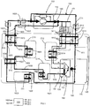
- a first embodiment of an NMR system 100 according to the invention is described below with reference to the figure 1 .
- the NMR system 100 mainly comprises a compressor 110, an NMR device 120, an insulated enclosure 130 and a first embodiment of a pipeline system 150.
- the NMR device 120 comprises a rotor or a sample holder 121 comprising a turbine 1211.
- the NMR device 120 is arranged, in particular the rotor is guided, so that the sample can be rotated along a particular axis called "magic angle".
- the insulated enclosure 130 comprises a heat shield 140.
- the enclosure preferably encloses the NMR device 120 and a portion of the piping system 150.
- the pipe system 150 mainly comprises an exhaust circuit 160 for driving a refrigerant fluid from the NMR device 120 to the compressor 110 and a supply circuit 180 for driving the refrigerant fluid from the compressor 110 to the NMR device 120.
- the exhaust circuit 160 comprises a first exhaust branch 161 and a second exhaust branch 162.
- the exhaust circuit 160 splits into the first and second exhaust branches 161, 162 just after the device NMR 120.
- the two exhaust branches 161, 162 meet just before the compressor.
- the first and second branches 161, 162 are preferably parallel branches.
- the first exhaust branch 161 mainly comprises a line 1612 of a first exchanger E11.
- the first exhaust branch 161 obviously also includes lines 1611 and 1613 completing the line 1612 so as to guide part of the refrigerant escaping from the NMR device 120 to the compressor 110.
- a first portion of the refrigerant escaping from the NMR device 120 returns to the compressor 110 through the first exchanger E11.
- the second exhaust branch 162 mainly comprises a line 1622 of a first cryocooler C11, a line 1624 of a second exchanger E12 and a line 1626 of a third exchanger E13.
- the second exhaust branch 162 obviously also includes lines 1621, 1623, 1625, 1627 completing the lines 1622, 1624, 1626 so as to guide a portion of the refrigerant escaping from the NMR device 120 to the compressor 110.
- a second part of the refrigerant escaping from the NMR device 120 returns to the compressor 110 by passing through the first cryocooler C11, the second heat exchanger E12 and the third heat exchanger E13.
- it passes through these elements in this order.
- the first and second exhaust branches 161, 162 simultaneously conduct the refrigerant from the NMR device 120 to the compressor 110.
- these first and second exhaust branches 161, 162 connect a fluid outlet of the NMR device 120 at a fluid inlet of the compressor 110 being deprived, in particular at at least one of their lines 1611 to 1613 and 1621 to 1626, of at least one redirection element and / or authorization / prohibition of passage of such a refrigerant, such as a valve.
- a flow regulator 1628 described below does not constitute a redirection element and / or authorization / ban passage.
- the supply circuit comprises a third supply branch 181 and a fourth supply branch 182.
- the supply circuit splits into the third and fourth supply branches 181, 182 just after the compressor 110. More preferably, the two feed branches 181, 182 remain separated into the NMR device 120.
- the third and fourth branches 181, 182 are preferably parallel branches.
- the third supply branch 181 mainly comprises one or more lines 1812 in the first exchanger E11 and one or more lines 1814 in a second cryocooler C12.
- the third supply branch obviously also includes lines completing the lines 1812 and 1814 so as to guide a portion of the compressor refrigerant to the NMR device 120.
- a first portion of the refrigerant flows from the compressor to the NMR device 120 through the first exchanger E11 and the second cryocooler C12.
- the fluid passes through the different elements in this order.
- the fourth supply branch 182 mainly comprises a line 1823 of the third exchanger E13, a line 1825 of a third cryocooler C13, a line 1827 of the second exchanger E12 and a line 1829 of a fourth cryocooler C14.
- the fourth supply branch 182 also obviously includes lines 1822, 1824, 1826, 1828 and 1830 completing the lines 1823, 1825, 1827 and 1829 so as to guide a portion of the refrigerant fluid of the compressor 110 to the NMR device 120.
- a second part of the refrigerant flows from the compressor 110 to the NMR device 120 through the third exchanger E13, the third cryocooler C13, the second exchanger E12 and the fourth cryocooler C14.
- the fluid passes through the different elements in this order.
- the first exchanger E11 and the second cryocooler C12 and have, at the third branch 181 as many pipes as sub-branches.
- the second portion of fluid passing through the supply circuit is constituted by a second flow whose function is to bring the sample to a suitable temperature.
- the fourth branch 182 which conducts this second portion of the fluid also conducts the single flow of this second fluid portion here the second flow whose sole function is to bring the sample to this adequate temperature.
- the second branch 162 includes a flow regulator 1628.
- the third branch 181 comprises three flow regulators 1811. They make it possible to regulate and / or regulate the flows flowing in the three sub-branches.
- the fourth branch 182 includes a flow regulator 1821.
- regulators 1628, 1811, 1821 are preferably of the flowmeter-regulator type, that is to say that they also make it possible to measure flow rates.
- the channeling system 150 also includes a control module 105 such as a microcontroller for receiving flow information and calculating accordingly orders that are transmitted to the controllers 1628, 1811, 1821. These orders determine configurations of the different regulators 1628, 1811, 1821.
- a control module 105 such as a microcontroller for receiving flow information and calculating accordingly orders that are transmitted to the controllers 1628, 1811, 1821. These orders determine configurations of the different regulators 1628, 1811, 1821.
- a second embodiment of an NMR system 200 according to the invention is described below with reference to the figure 2 .
- the NMR system 200 mainly comprises a compressor 210, an NMR device 220, an insulated enclosure 230 and a first embodiment of a piping system 250.
- the NMR device 220 comprises a rotor or a sample holder 121 comprising a turbine 2211.
- the NMR device 220 is arranged, in particular the rotor is guided, so that the sample can be rotated along a particular axis called "magic angle".
- the insulated enclosure 230 comprises a heat shield 240.
- the enclosure 230 preferably encloses the NMR device 220 and a part of the piping system 250.
- the pipe system 250 mainly comprises an exhaust circuit 260 for driving a refrigerant fluid from the NMR device 220 to the compressor 210 and a supply circuit 280 for driving the refrigerant fluid from the compressor 210 to the NMR device 220.
- the exhaust circuit 260 comprises a first exhaust branch 261 and a second exhaust branch 262.
- the exhaust circuit 260 splits into the first and second exhaust branches 261, 262 just after the device NMR 220.
- the two exhaust branches 261, 262 meet just before the compressor 210.
- the first and second branches 261, 262 are preferably parallel branches.
- the first exhaust branch 261 mainly comprises a line 2612 of a first exchanger E21.
- the first exhaust branch 261 obviously also includes lines 2611 and 2613 completing line 2612 so as to guide part of the refrigerant escaping from the NMR device 220 to the compressor 210.
- a first portion of the refrigerant escaping from the NMR device 220 returns to the compressor 210 through the first exchanger E21.
- the second exhaust branch 262 mainly comprises a line 2622 of a stage C212 of a cryocooler C21, a line 2624 of a second exchanger E22 and a line 2626 of a third exchanger E23.
- this stage C212 of the cryocooler C21 can also be identified as first or fourth cryocoolers by analogy with the first and fourth cryocoolers C11, C14 of the piping system 150 of the first embodiment of the NMR system 100.
- this stage C212 presents substantially the same characteristics as cryocoolers C11, C14 and fills significantly in the system 250 functions similar to those of the latter.
- the second exhaust branch 262 obviously also includes lines 2621, 2623, 2625, 2627 completing the lines 2622, 2624, 2626 so as to guide a portion of the refrigerant escaping from the NMR device 220 to the compressor 210.
- a second part of the refrigerant escaping from the NMR device 220 returns to the compressor 210 by passing through the stage C212 of the cryocooler C21, the second exchanger E22 and the third exchanger E23.
- it passes through these elements in this order.
- the first and second exhaust branches 261, 262 simultaneously conduct the cooling fluid from the NMR device 220 to the compressor 210.
- these first and second exhaust branches 261, 262 connect a fluid outlet of the NMR device 220 to a fluid inlet of the compressor 210, in particular being missing at at least one of their lines 2611 to 1613 and 2621 to 2626, at least one redirection element and / or authorization / prohibition of passage of such a refrigerant, such as a valve.
- a flow regulator 2628 described below does not constitute a redirection element and / or authorization / prohibition passage.
- the supply circuit comprises a third supply branch 281 and a fourth supply branch 282.
- the supply circuit splits into the third and fourth supply branches 281, 282 just after the compressor 210. More preferably, the two power supply branches 281, 282 remain separated into the NMR device 220.
- the third and fourth branches 281, 282 are preferably parallel branches.
- the third supply branch 281 mainly comprises one or more lines 2812 in the first exchanger E21 and one or more lines 1814 in a stage C211 of the cryocooler C21.
- this stage C211 of the cryocooler C21 can also be identified as second or third cryorefrigerator by analogy with the second and third cryorefrigerators C12 and C13 of the piping system 150 of the first embodiment of the NMR system 100.
- this stage C211 has substantially the same characteristics as these cryocoolers C12 and C13 and fills significantly in this system 250 functions similar to those of the latter.
- the third supply branch 281 obviously also includes lines completing the lines 2812 and 2814 so as to guide a portion of the refrigerant fluid of the compressor 210 to the device NMR 220.
- a first portion of the refrigerant flows from the compressor 210 to the NMR device 220 through the first exchanger E21 and the C211 stage of the cryocooler C21.
- the fluid passes through the different elements in this order.
- the fourth supply branch 282 mainly comprises a line 2823 of the third exchanger E23, a line 2825 of the stage C211 of the cryocooler C21, a line 2827 of the second exchanger E22 and a line 2829 of the stage C212 of the cryocooler C21.
- the fourth supply branch 282 also obviously includes lines 2822, 2824, 2826, 2828 and 2830 completing the lines 2823, 2825, 2827 and 2829 so as to guide a portion of the refrigerant fluid of the compressor 210 to the NMR device 220.
- a second part of the refrigerant circulates from the compressor 210 to the NMR device 220 through the third exchanger E23, the C211 stage of the cryocooler C21, the second exchanger E22 and the C212 stage of the cryocooler C21.
- the fluid passes through the different elements in this order.
- the second portion of fluid passing through the supply circuit is constituted by a second flow whose function is to bring the sample to a suitable temperature.
- the fourth branch 282 which leads this second portion of the fluid also conducts the single flow of this second fluid portion here the second flow whose sole function is to bring the sample to this adequate temperature.
- the second branch 262 includes a flow regulator 2628.
- the third branch 281 comprises three flow regulators 2811. They make it possible to regulate and / or regulate the flows flowing in the three sub-branches.
- the fourth branch 282 includes a flow regulator 2821.
- regulators 2628, 2811, 2821 are preferably of the flowmeter-regulator type, that is to say that they also make it possible to measure flow rates.
- the piping system 250 also includes a control module 205 as a microcontroller for receiving flow information and calculating accordingly commands that are transmitted to the regulators 2628, 2811, 2821. These orders determine configurations of the different regulators 2628, 2811.2821.
- references of identical elements or having the same function differs only in their first digit: a "1" for the elements of the first mode and a "2" for the elements of the second mode.
- the different heat exchangers E11 to E13 and E21 to E23 are preferably countercurrent heat exchangers.
- the fluid used is for example helium. It is understood that this fluid may be a gaseous or liquid type fluid that can be maintained in particular at a cryogenic temperature. The fluid may further undergo phase changes. Thus, the fluid can be gaseous in one part of the system and liquid in another part of the system.
- the NMR device 120, 220 comprises the rotor or sample holder 121, 221 and the stator 122, 222.
- the invention also relates to a method of operating a system 100, 200, 150, 250 described above.
- the first and second branches 161, 261, 162, 262 conduct simultaneously the refrigerant, in particular between the RMN device 120, 220 of the NMR system 100, 200 and the compressor RMB of the NMR system 100, 200.
- the flow rates in the different branches are regulated.
- the flow control is such that the fluid flow rates in the first and third branches 161, 261, 181, 281 are equal or substantially equal.
- the regulation of the flows is such that the flows in the second and fourth branches 162, 262, 182, 282 are equal or substantially equal.
- the regulators 1628 and 1821 or 2628 and 2821 are slaved to respect this equality.
- the flow rates mentioned above are mass flow rates.
- the flow rates are regulated so that the fluid flow rates in the first and third branches 1161, 261, 181, 281 are equal or substantially equal and / or in that the fluid flow rates of so that the flows in the second and fourth branches 162, 262, 182, 282 are equal or substantially equal.
- the fact of separating the flow whose function is to bring the sample to a suitable temperature of the other flows whose function is to rotate the sample holder 121, 221, to create an aerostatic bearing of levitation the rotor in a stator 122, 222 of the NMR device 120, 220, or to cool the heat shield 140, 240 protecting the NMR device 120, 220 from the thermal radiation provides a great flexibility in the operation of the NMR system 100, 200.
Landscapes
- Physics & Mathematics (AREA)
- Engineering & Computer Science (AREA)
- Condensed Matter Physics & Semiconductors (AREA)
- General Physics & Mathematics (AREA)
- Mechanical Engineering (AREA)
- Thermal Sciences (AREA)
- General Engineering & Computer Science (AREA)
- Sampling And Sample Adjustment (AREA)
- Structures Of Non-Positive Displacement Pumps (AREA)
Abstract
Description
- L'invention concerne un système de canalisation de fluide d'un système RMN. L'invention concerne aussi un système RMN comprenant un tel système de canalisation. L'invention concerne encore un procédé de fonctionnement de tels systèmes.
- Un dispositif RMN (ou dispositif de détection ou d'analyse à Résonance Magnétique Nucléaire) comprend un porte-échantillon mis en rotation dans un champ magnétique statique et exposé à un second champ magnétique perpendiculaire au premier et créé par une bobine radiofréquence qui reçoit en retour un signal qui est analysé pour en déduire des informations sur un échantillon solide disposé dans le porte-échantillon. Selon une réalisation de l'état de la technique, plusieurs flux gazeux provenant d'une même source, un container standard comme une bouteille d'hélium montée en pression, sont dirigés vers la sonde du dispositif qui comprend le porte-échantillon. Un premier flux a pour fonction de mettre en rotation le porte-échantillon, en agissant sur les pales ou ailettes d'une turbine d'entraînement d'un rotor qui comprend le porte-échantillon. Un second flux a pour fonction de porter l'échantillon à une certaine température. Un troisième flux crée un palier aérostatique de sustentation du rotor dans le stator. Éventuellement, un quatrième flux permet de refroidir un écran thermique protégeant le dispositif d'un rayonnement thermique.
- Les flux sont assurés et canalisés par un système de canalisation. Le système de canalisation et le dispositif RMN forment un système RMN.
- La recherche de la meilleure performance d'analyse d'un échantillon à l'état solide par RMN utilise une mise en rotation de l'échantillon selon un axe particulier appelé « l'angle magique ». Il est important d'atteindre une vitesse de rotation élevée. D'autre part, l'augmentation de l'intensité des champs magnétiques, qui atteint actuellement environ 20 Tesla, a amélioré la sensibilité de la détection RMN. Il est toutefois très difficile aujourd'hui d'augmenter cette intensité.
- Les solutions existantes restent imparfaites et insuffisantes et il existe donc un besoin général d'amélioration de la détection et de l'analyse par RMN d'un échantillon solide.
- Depuis quelques années, laboratoires de recherche et industriels travaillent au développement de prototypes afin d'atteindre plusieurs dizaine de kilohertz de fréquence de rotation de l'échantillon et cela dans la gamme de température 10K-100K.
- Plus précisément, l'échantillon à étudier ou à qualifier par cette technique est placé dans un tube qui a la fonction de rotor. Ce tube équipé d'un bouchon à une extrémité si l'autre est borgne ou de deux bouchons forme le porte-échantillon ou rotor et est installé dans un stator. Les bouchons sont usinés de telle sorte qu'ils forment des turbines (donc une ou deux turbines) par rotor. Les turbines sont alimentées par les flux de gaz distribués par le stator. Le rotor est ainsi mis en rotation. L'ensemble rotor-stator constituant une machine tournante est pourvu de paliers gazeux dont la configuration peut-être du type aérodynamique, aérostatique ou hybride. Les paliers sont également alimentés par les flux gazeux via le stator. Un autre flux gazeux permet de porter l'échantillon à la température souhaitée pour en réaliser l'étude. Un tel système est de petite taille puisque le diamètre du rotor porte-échantillon peut être par exemple compris entre 0,7 mm et 7 mm. Ceci implique une forte compacité de l'ensemble stator-rotor.
- Les différents flux gazeux peuvent être distribués radialement ou tangentiellement sur le rotor. Ils peuvent être évacués axialement, du centre vers l'extérieur du stator. Les flux gazeux alimentant la ou les turbines sont évacués les plus facilement puisque la ou les turbines sont situées aux extrémités du rotor. Les flux gazeux alimentant les paliers arrivent sur le rotor à proximité des turbines. Le flux gazeux refroidissant l'échantillon arrive sur le rotor dans sa zone centrale.
- Cet agencement fluidique est tel que le flux refroidissant l'échantillon balaye, quand il est évacué axialement, les zones des paliers, puis les zones des turbines. Les flux alimentant les paliers balayent quant à eux, quand ils sont évacués axialement, les zones des turbines. Les flux alimentant les paliers créent des coins fluides dans les zones des paliers. Il s'ensuit une relative étanchéité telle que les flux alimentant les turbines situées aux extrémités du rotor ne peuvent s'évacuer vers la zone centrale du rotor. Ainsi, les flux alimentant les turbines ne peuvent pas influencer la température de la zone centrale du rotor où se trouve l'échantillon. Les flux alimentant les paliers sont dirigés et évacués dans l'axe du rotor vers ses extrémités poussés par le flux refroidissant la zone centrale du rotor et l'échantillon.
- Les matériaux utilisés pour la fabrication du tube et des turbines (céramiques et plastiques) sont de mauvais conducteurs thermiques. Il s'ensuit que le flux thermique (par conduction solidienne) des extrémités du rotor vers la zone centrale du rotor est négligeable. Une zone de contact aux interfaces du tube et des turbines crée de plus une résistance thermique de contact qui limite encore d'autant le flux thermique.
- En conséquence, les températures des flux alimentant les paliers et les turbines peuvent être supérieures à celle du flux refroidissant l'échantillon.
- Pour fonctionner à très basse température, il convient de fournir des gaz froids.
- Dans la gamme de température 90K à 300K, l'azote apparaît comme le fluide à utiliser à l'évidence dès lors qu'il est non dangereux, peu coûteux et simple d'utilisation.
- A plus basse température et jusqu'au environ de 10K, l'hélium s'impose comme l'élément à utiliser de par ses caractéristiques thermo-physiques. Au-dessus de 90K, mis à part les aspects thermiques, c'est également le cas puisque l'hélium permet d'obtenir des fréquences de rotation deux fois supérieures à celle générées avec de l'azote. Cependant, quoiqu'indispensable pour faire de la RMN entre 10K et 90K, l'hélium génère des coûts de fonctionnement rapidement prohibitifs. Ainsi, très peu de laboratoires dans le monde peuvent réaliser des analyses RMN, même expérimentalement, en dessous de 100K.
- Deux solutions sont actuellement appliquées pour pallier cette difficulté.
- Comme théoriquement il est seulement nécessaire de refroidir l'échantillon, en négligeant des pertes thermiques, seul le flux de refroidissement de l'échantillon requiert du fluide réfrigéré. Ainsi, un prototype développé il y a plusieurs années utilise l'azote comme fluide pour alimenter les paliers et les turbines et l'hélium comme fluide de refroidissement de l'échantillon. Cette technique nécessite un rotor allongé pour réduire l'influence thermique de l'azote à 90K, utilisé aux extrémités du rotor (dans les zones des paliers et des turbines, sur la zone centrale). Cette zone centrale est alimentée par un flux d'hélium entre 10K et 90K. Quoiqu'astucieuse, cette solution est technologiquement complexe à mettre en oeuvre et n'est pas durable pour l'obtention de spectres RMN de longues durées.
- Une autre solution consiste à récupérer le gaz à l'échappement du stator et à le remettre en circulation dans le dispositif par une boucle fermée pressurisée. Dans cette boucle, le gaz est descendu à la température de fonctionnement souhaitée par une source cryogénique via un ou des échangeurs thermiques. L'ensemble travaille suivant un cycle de Brayton. Compte tenu de la forte compacité de ce système pneumatique miniature mais surtout du fonctionnement en boucle fermée, la seule solution semble résider dans l'utilisation de flux qui sont tous à la même température. Le gaz récupéré à l'échappement du stator commun aux différents flux est injecté dans un échangeur thermique à contre-courant afin d'échanger de la chaleur avec les différents flux alimentant l'ensemble stator-rotor pour pré-refroidir ces flux. Si les températures des flux alimentant les paliers et/ou les turbines étaient supérieures à la température du flux refroidissant l'échantillon, la température du gaz d'échappement serait trop haute et déséquilibrerait le cycle thermique qui ne serait plus viable.
- Le fonctionnement avec des températures de flux identiques n'est pas très problématique jusque vers 50K. En dessous, le fonctionnement devient plus complexe pour différentes raisons.
- En dessous de 30K, les caractéristiques thermophysiques de l'hélium varient très fortement et non linéairement et la maîtrise de la rotation devient délicate et sensible pour assurer une fréquence de rotation constante.
- Au niveau des paliers, la forte variation de la densité de l'hélium entraîne une contraction importante du volume gazeux du palier. Ainsi, le débit doit être ajusté en conséquence et rapidement pour assurer une raideur adaptée et constante du palier afin de préserver une rotation sans excentration perturbatrice de la fréquence, voire destructrice du rotor.
- Au niveau des turbines, la puissance mécanique reçue sur les pâles est fonction du rapport de la valeur de débit massique élevée au cube sur la valeur de densité du gaz élevée au carré. Le gaz utilisé pour passer d'une rotation à température ambiante, c'est-à-dire 300K, à une rotation à 10K est nécessairement de l'hélium. Or la densité de l'hélium est sensiblement multipliée par 30 entre 300K et 10K. Le débit massique doit donc être multiplié par 10 sur le même intervalle de températures pour obtenir une puissance constante.
- Ainsi, le débit à appliquer pour entretenir la rotation à une température T comprise entre 300K et 8K relativement au débit initial établi à la température ambiante, est quasi exponentiel et dépendant de la loi suivante :

- Entre 300K et 50K, le débit est augmenté d'un facteur 3 pour conserver une fréquence de rotation constante alors que, de 50K à 25K, ce facteur est quasiment de 2. Globalement, pour un fonctionnement constant à 30kHZ jusqu'à 10K le débit massique doit être théoriquement multiplié par 10. Par exemple, un rotor de sonde RMN de 2 mm de diamètre va nécessiter un débit compris entre 0,1 et 0,2 g.s-1 pour tourner à 30kHz à la température ambiante. Ce débit devra être de 1 à 2 g.s-1 pour fonctionner à 10K.
- En conséquence, le dispositif de recirculation et la source cryogénique (constitué d'un échangeur et d'un cryoréfrigérateur) doivent être très adaptables mais surtout surdimensionnés à haute température pour traiter ces très fortes variations de débits et assurer un fonctionnement correct à très basse température.
- Un dernier problème est dû à l'accouplement entre le tube et les turbines. Pour des raisons de fiabilité mécanique mais également économique, le tube et les turbines sont fabriqués dans des matériaux différents. Le tube qui doit offrir la plus faible susceptibilité magnétique possible est par exemple en zirconia (dioxyde de zirconium), matériau obtenu par frittage et sensible aux chocs, raison pour laquelle les turbines dans lesquelles les ailettes sont pratiquées, sont réalisées par exemple en un polymère à base de polyimide comme du Vespel® (marque déposée par DuPont). Ces deux matériaux offrent de bonnes caractéristiques pour travailler dans le domaine cryogénique mais ont des contractions différentielles d'autant plus éloignées que la température est basse. La turbine montée serrée à température ambiante dans le tube l'est de moins en moins lorsque la température décroît. La perte d'une turbine peut alors survenir aléatoirement en fonction des brusques changements de régimes de débits comme explicité précédemment.
- Il apparaît donc que, pour des raisons dynamiques et mécaniques, il est souhaitable de mettre en oeuvre des flux alimentant les paliers et les turbines à des températures moins basses que celle du flux refroidissant l'échantillon. Toutefois, en adoptant cette solution, les dispositifs connus de l'art antérieur ne peuvent fonctionner correctement.
- Le but de l'invention est de remédier aux inconvénients cités précédemment et d'améliorer les systèmes RMN connus de l'art antérieur. En particulier, l'invention propose un système de canalisations simple et qui permette de réaliser une gestion efficace du fluide frigorifique.
- Selon l'invention, le système de canalisation de fluide pour système RMN comprend un circuit d'échappement du système RMN comprenant une première branche de circulation de fluide et une deuxième branche de circulation de fluide.
- De préférence, dans ce circuit d'échappement, les première et deuxième branches conduisent de manière simultanée le fluide frigorifique du dispositif RMN au compresseur. Ainsi, un débit non nul de fluide frigorifique circule simultanément dans les première et deuxième branches lorsque le dispositif RMN fonctionne.
- La configuration du circuit d'échappement comprenant ces première et deuxième branches participe à constituer un système de canalisation simple tout en améliorant l'efficacité de la gestion du fluide frigorifique dans ce système et ce, en contribuant à la mise en oeuvre d'un flux ayant pour fonction de refroidir un échantillon du dispositif RMN à une température adéquate, ce flux étant séparé d'autres flux assurant différentes autres fonctions dans le système de canalisation à des températures plus élevées comme notamment l'alimentation de paliers et de turbines du dispositif RMN. Une telle configuration offre ainsi une importante souplesse de fonctionnement du système RMN.
- La première branche peut ne pas comprendre de conduite de cryoréfrigérateur et/ou la deuxième branche peut comprendre une conduite d'un premier cryoréfrigérateur.
- La première branche peut comprendre une conduite d'un premier échangeur et/ou la deuxième branche peut comprendre une conduite d'un deuxième échangeur et une conduite d'un troisième échangeur.
- Le système peut comprendre un circuit d'alimentation du système RMN comprenant une troisième branche de circulation de fluide et une quatrième branche de circulation de fluide.
- La troisième branche de circulation de fluide peut comprendre plusieurs sous-branches, notamment une première sous-branche de circulation d'un premier flux qui a pour fonction de mettre en rotation un porte-échantillon en agissant sur des pales ou ailettes d'une turbine d'entraînement d'un rotor du dispositif RMN, le rotor comprenant le porte-échantillon, et/ou une deuxième sous-branche de circulation d'un troisième flux qui a pour fonction de créer un palier de sustentation du rotor dans un stator du dispositif RMN et/ou une troisième sous-branche de circulation d'un quatrième flux qui a pour fonction de refroidir un écran thermique protégeant le dispositif RMN de rayonnements thermiques.
- La troisième branche peut comprendre au moins une conduite d'un deuxième cryoréfrigérateur et/ou la quatrième branche peut comprendre une conduite d'un troisième cryoréfrigérateur et une conduite d'un quatrième cryoréfrigérateur.
- Le deuxième cryoréfrigérateur et le troisième cryoréfrigérateur peuvent être un même cryoréfrigérateur, notamment un même étage d'un cryoréfrigérateur.
- Le premier cryoréfrigérateur et le quatrième cryoréfrigérateur peuvent être un même cryoréfrigérateur, notamment un même étage d'un cryoréfrigérateur.
- Le système peut comprendre un seul cryoréfrigérateur, notamment un cryoréfrigérateur comprenant un premier étage et un deuxième étage. Autrement dit, ce seul cryoréfrigérateur du système RMN comprend deux étages remplissant chacun les fonctions de deux cryoréfrigérateurs telles que celles des premier et quatrième cryoréfrigérateurs, et des deuxième et troisième cryoréfrigérateurs.
- La troisième branche peut comprendre au moins une conduite du premier échangeur et/ou la quatrième branche peut comprendre une conduite du troisième échangeur et une conduite du deuxième échangeur.
- La deuxième branche peut comprendre un régulateur de débit.
- La troisième branche peut comprendre au moins un régulateur de débit et/ou la quatrième branche peut comprendre un régulateur de débit.
- Un système RMN selon l'invention comprend un système de canalisation tel que défini précédemment et un dispositif RMN, notamment un dispositif d'analyse RMN.
- Selon un premier aspect, un procédé de fonctionnement d'un système tel que défini précédemment, est caractérisé en ce que les première et deuxième branches conduisent de manière simultanée le fluide frigorifique, notamment entre un dispositif RMN du système RMN et un compresseur du système RMN.
- De préférence, on régule les débits de sorte que les débits de fluide dans les première et troisième branches soient égaux ou sensiblement égaux et/ou on régule les débits de fluide de sorte que les débits dans les deuxième et quatrième branches soient égaux ou sensiblement égaux.
- Selon un deuxième aspect, un procédé de fonctionnement d'un système tel que défini précédemment, est caractérisé en ce qu'on régule les débits de sorte que les débits de fluide dans les première et troisième branches soient égaux ou sensiblement égaux et/ou en ce qu'on régule les débits de fluide de sorte que les débits dans les deuxième et quatrième branches soient égaux ou sensiblement égaux.
- Les objets, caractéristiques et avantages de la présente invention sont exposés en détail dans la description suivante de deux modes de réalisation particuliers en référence au dessin annexé. Ces modes de réalisation sont non limitatifs. Le dessin annexé est composé comme suit :
- La
figure 1 représente schématiquement un premier mode de réalisation d'un système RMN selon l'invention. - La
figure 2 représente schématiquement un deuxième mode de réalisation d'un système RMN selon l'invention. - Un premier mode de réalisation d'un système RMN 100 selon l'invention est décrit ci-après en référence à la
figure 1 . - Le système RMN 100 comprend principalement un compresseur 110, un dispositif RMN 120, une enceinte calorifugée 130 et un premier mode de réalisation d'un système de canalisation 150. Le dispositif RMN 120 comprend un rotor ou un porte-échantillon 121 comprenant une turbine 1211. Le dispositif RMN 120 est agencé, en particulier le rotor est guidé, de sorte que l'échantillon puisse être mis en rotation selon un axe particulier appelé « angle magique ».
- De préférence, l'enceinte calorifugée 130 comprend un écran thermique 140. L'enceinte renferme de préférence le dispositif RMN 120 et une partie du système de canalisation 150.
- Le système de canalisation 150 comprend principalement un circuit d'échappement 160 permettant de conduire un fluide frigorifique du dispositif RMN 120 au compresseur 110 et un circuit d'alimentation 180 permettant de conduire le fluide frigorifique du compresseur 110 au dispositif RMN 120.
- Le circuit d'échappement 160 comprend une première branche d'échappement 161 et une deuxième branche d'échappement 162. De préférence, le circuit d'échappement 160 se divise en les première et deuxième branches d'échappement 161, 162 juste après le dispositif RMN 120. De préférence encore, les deux branches d'échappement 161, 162 se rejoignent juste avant le compresseur. Ainsi, les première et deuxième branches 161, 162 sont de préférence des branches parallèles.
- La première branche d'échappement 161 comprend principalement une conduite 1612 d'un premier échangeur E11. La première branche d'échappement 161 comprend évidemment également des conduites 1611 et 1613 complétant la conduite 1612 de sorte à guider une partie du fluide frigorifique s'échappant du dispositif RMN 120 vers le compresseur 110. Ainsi, une première partie du fluide frigorifique s'échappant du dispositif RMN 120 retourne au compresseur 110 en traversant le premier échangeur E11.
- La deuxième branche d'échappement 162 comprend principalement une conduite 1622 d'un premier cryoréfrigérateur C11, une conduite 1624 d'un deuxième échangeur E12 et une conduite 1626 d'un troisième échangeur E13. La deuxième branche d'échappement 162 comprend évidemment également des conduites 1621, 1623, 1625, 1627 complétant les conduites 1622, 1624, 1626 de sorte à guider une partie du fluide frigorifique s'échappant du dispositif RMN 120 vers le compresseur 110. Ainsi, une deuxième partie du fluide frigorifique s'échappant du dispositif RMN 120 retourne au compresseur 110 en traversant le premier cryoréfrigérateur C11, le deuxième échangeur E12 et le troisième échangeur E13. Avantageusement, il traverse ces éléments dans cet ordre.
- Dans cette configuration, les première et deuxième branches d'échappement 161, 162 conduisent de manière simultanée le fluide frigorifique provenant du dispositif RMN 120 vers le compresseur 110. En effet, de préférence, ces première et deuxième branches d'échappement 161, 162 relient une sortie de fluide du dispositif RMN 120 à une entrée de fluide du compresseur 110 en étant dépourvues, notamment au niveau d'au moins une de leurs conduites 1611 à 1613 et 1621 à 1626, d'au moins un élément de redirection et/ou d'autorisation/interdiction de passage d'un tel fluide frigorifique, comme une vanne. On notera qu'un régulateur de débit 1628 décrit par la suite ne constitue pas un élément de redirection et/ou d'autorisation/interdiction de passage.
- Le circuit d'alimentation comprend une troisième branche d'alimentation 181 et une quatrième branche d'alimentation 182. De préférence, le circuit d'alimentation se divise en les troisième et quatrième branches d'alimentation 181, 182 juste après le compresseur 110. De préférence encore, les deux branches d'alimentation 181, 182 demeurent séparées jusque dans le dispositif RMN 120. Ainsi, les troisième et quatrième branches 181, 182 sont de préférence des branches parallèles.
- La troisième branche d'alimentation 181 comprend principalement une ou plusieurs conduites 1812 dans le premier échangeur E11 et une ou plusieurs conduites 1814 dans un deuxième cryoréfrigérateur C12. La troisième branche d'alimentation comprend évidemment également des conduites complétant les conduites 1812 et 1814 de sorte à guider une partie du fluide frigorifique du compresseur au dispositif RMN 120. Ainsi, une première partie du fluide frigorifique circule du compresseur au dispositif RMN 120 en traversant le premier échangeur E11 et le deuxième cryoréfrigérateur C12. De préférence, le fluide traverse les différents éléments dans cet ordre.
- La quatrième branche d'alimentation 182 comprend principalement une conduite 1823 du troisième échangeur E13, une conduite 1825 d'un troisième cryoréfrigérateur C13, une conduite 1827 du deuxième échangeur E12 et une conduite 1829 d'un quatrième cryoréfrigérateur C14. La quatrième branche d'alimentation 182 comprend évidemment également des conduites 1822, 1824, 1826, 1828 et 1830 complétant les conduites 1823, 1825, 1827 et 1829 de sorte à guider une partie du fluide frigorifique du compresseur 110 au dispositif RMN 120. Ainsi, une deuxième partie du fluide frigorifique circule du compresseur 110 au dispositif RMN 120 en traversant le troisième échangeur E13, le troisième cryoréfrigérateur C13, le deuxième échangeur E12 et le quatrième cryoréfrigérateur C14. De préférence, le fluide traverse les différents éléments dans cet ordre.
- La première partie de fluide transitant dans le circuit d'alimentation est constituée par :
- un premier flux qui a pour fonction de mettre en rotation le porte-échantillon 121, en agissant sur des pales ou ailettes de la turbine d'entraînement 1211 du rotor du dispositif RMN 120, le rotor comprenant le porte-échantillon 121 ; et
- un troisième flux qui crée un palier aérostatique de sustentation du rotor dans un stator 122 du dispositif RMN 120, et, éventuellement,
- un quatrième flux permet de refroidir l'écran thermique 140 protégeant le dispositif RMN 120 des rayonnements thermiques.
- Ainsi, la troisième branche de circulation 181 comprend trois sous-branches :
- une première sous-branche de circulation du premier flux qui a pour fonction de mettre en rotation le porte-échantillon 121, en agissant sur les pales ou ailettes de la turbine d'entraînement du rotor du dispositif RMN 120, le rotor comprenant le porte-échantillon 121 ;
- une deuxième sous-branche de circulation du troisième flux qui a pour fonction de créer le palier aérostatique de sustentation du rotor dans le stator 122 du dispositif RMN 120 ;
- une troisième sous-branche de circulation du quatrième flux qui a pour fonction de refroidir l'écran thermique 140 protégeant le dispositif RMN 120 de rayonnements thermiques.
- Le premier échangeur E11 et le deuxième cryoréfrigérateur C12 présentent ainsi, au niveau de la troisième branche 181 autant de conduites que de sous-branches.
- La deuxième partie de fluide transitant dans le circuit d'alimentation est constituée par un second flux qui a pour fonction de porter l'échantillon à une température adéquate. Ainsi, la quatrième branche 182 qui conduit cette deuxième partie du fluide conduit également l'unique flux de cette deuxième portion de fluide ici le second flux dont la seule fonction est de porter l'échantillon à cette température adéquate.
- La deuxième branche 162 comprend un régulateur de débit 1628.
- La troisième branche 181 comprend trois régulateurs de débit 1811. Ils permettent de régler et/ou réguler les débits circulant dans les trois sous-branches.
- La quatrième branche 182 comprend un régulateur de débit 1821.
- Ces régulateurs 1628, 1811, 1821 sont de préférence du type débitmètre-régulateur, c'est-à-dire qu'ils permettent également de mesurer les débits.
- Le système de canalisation 150 comprend également un module de commande 105 comme un microcontrôleur permettant de recevoir des informations de débits et de calculer en conséquence des ordres de commandes qui sont transmis aux régulateurs 1628, 1811, 1821. Ces ordres déterminent des configurations des différents régulateurs 1628, 1811, 1821.
- Un deuxième mode de réalisation d'un système RMN 200 selon l'invention est décrit ci-après en référence à la
figure 2 . - Le système RMN 200 comprend principalement un compresseur 210, un dispositif RMN 220, une enceinte calorifugée 230 et un premier mode de réalisation d'un système de canalisations 250. Le dispositif RMN 220 comprend un rotor ou un porte-échantillon 121 comprenant une turbine 2211. Le dispositif RMN 220 est agencé, en particulier le rotor est guidé, de sorte que l'échantillon puisse être mis en rotation selon un axe particulier appelé « angle magique ».
- De préférence, l'enceinte calorifugée 230 comprend un écran thermique 240. L'enceinte 230 renferme de préférence le dispositif RMN 220 et une partie du système de canalisation 250.
- Le système de canalisation 250 comprend principalement un circuit d'échappement 260 permettant de conduire un fluide frigorifique du dispositif RMN 220 au compresseur 210 et un circuit d'alimentation 280 permettant de conduire le fluide frigorifique du compresseur 210 au dispositif RMN 220.
- Le circuit d'échappement 260 comprend une première branche d'échappement 261 et une deuxième branche d'échappement 262. De préférence, le circuit d'échappement 260 se divise en les première et deuxième branches d'échappement 261, 262 juste après le dispositif RMN 220. De préférence encore, les deux branches d'échappement 261, 262 se rejoignent juste avant le compresseur 210. Ainsi, les première et deuxième branches 261, 262 sont de préférence des branches parallèles.
- La première branche d'échappement 261 comprend principalement une conduite 2612 d'un premier échangeur E21. La première branche d'échappement 261 comprend évidemment également des conduites 2611 et 2613 complétant la conduite 2612 de sorte à guider une partie du fluide frigorifique s'échappant du dispositif RMN 220 vers le compresseur 210. Ainsi, une première partie du fluide frigorifique s'échappant du dispositif RMN 220 retourne au compresseur 210 en traversant le premier échangeur E21.
- La deuxième branche d'échappement 262 comprend principalement une conduite 2622 d'un étage C212 d'un cryoréfrigérateur C21, une conduite 2624 d'un deuxième échangeur E22 et une conduite 2626 d'un troisième échangeur E23. On notera que cet étage C212 du cryoréfrigérateur C21 peut également être identifié comme premier ou quatrième cryoréfrigérateurs par analogie aux premier et quatrième cryoréfrigérateurs C11, C14 du système de canalisation 150 du premier mode de réalisation du système RMN 100. En effet, cet étage C212 présente sensiblement les mêmes caractéristiques que ces cryoréfrigérateurs C11, C14 et remplit notablement dans le système 250 des fonctions similaires à celles de ces derniers.
- La deuxième branche d'échappement 262 comprend évidemment également des conduites 2621, 2623, 2625, 2627 complétant les conduites 2622, 2624, 2626 de sorte à guider une partie du fluide frigorifique s'échappant du dispositif RMN 220 vers le compresseur 210. Ainsi, une deuxième partie du fluide frigorifique s'échappant du dispositif RMN 220 retourne au compresseur 210 en traversant l'étage C212 du cryoréfrigérateur C21, le deuxième échangeur E22 et le troisième échangeur E23. Avantageusement, il traverse ces éléments dans cet ordre.
- Dans cette configuration, les première et deuxième branches d'échappement 261, 262 conduisent de manière simultanée le fluide frigorifique provenant du dispositif RMN 220 vers le compresseur 210. En effet, de préférence, ces première et deuxième branches d'échappement 261, 262 relient une sortie de fluide du dispositif RMN 220 à une entrée de fluide du compresseur 210 en étant dépourvues notamment au niveau d'au moins une de leurs conduites 2611 à 1613 et 2621 à 2626, d'au moins un élément de redirection et/ou d'autorisation/interdiction de passage d'un tel fluide frigorifique, comme une vanne. On notera qu'un régulateur de débit 2628 décrit par la suite ne constitue pas un élément de redirection et/ou d'autorisation/interdiction de passage.
- Le circuit d'alimentation comprend une troisième branche d'alimentation 281 et une quatrième branche d'alimentation 282. De préférence, le circuit d'alimentation se divise en les troisième et quatrième branches d'alimentation 281, 282 juste après le compresseur 210. De préférence encore, les deux branches d'alimentation 281,282 demeurent séparées jusque dans le dispositif RMN 220. Ainsi, les troisième et quatrième branches 281, 282 sont de préférence des branches parallèles.
- La troisième branche d'alimentation 281 comprend principalement une ou plusieurs conduites 2812 dans le premier échangeur E21 et une ou plusieurs conduites 1814 dans un étage C211 du cryoréfrigérateur C21. On notera que cet étage C211 du cryoréfrigérateur C21 peut également être identifié comme deuxième ou troisième cryoréfrigénérateur par analogie au deuxième et troisième cryoréfrigérateurs C12 et C13 du système de canalisation 150 du premier mode de réalisation du système RMN 100. En effet, cet étage C211 présente sensiblement les mêmes caractéristiques que ces cryoréfrigérateurs C12 et C13 et remplit notablement dans ce système 250 des fonctions similaires à celles de ces derniers. La troisième branche d'alimentation 281 comprend évidemment également des conduites complétant les conduites 2812 et 2814 de sorte à guider une partie du fluide frigorifique du compresseur 210 au dispositif RMN 220. Ainsi, une première partie du fluide frigorifique circule du compresseur 210 au dispositif RMN 220 en traversant le premier échangeur E21 et l'étage C211 du cryoréfrigérateur C21. De préférence, le fluide traverse les différents éléments dans cet ordre.
- La quatrième branche d'alimentation 282 comprend principalement une conduite 2823 du troisième échangeur E23, une conduite 2825 de l'étage C211 du cryoréfrigérateur C21, une conduite 2827 du deuxième échangeur E22 et une conduite 2829 de l'étage C212 du cryoréfrigérateur C21. La quatrième branche d'alimentation 282 comprend évidemment également des conduites 2822, 2824, 2826, 2828 et 2830 complétant les conduites 2823, 2825, 2827 et 2829 de sorte à guider une partie du fluide frigorifique du compresseur 210 au dispositif RMN 220. Ainsi, une deuxième partie du fluide frigorifique circule du compresseur 210 au dispositif RMN 220 en traversant le troisième échangeur E23, l'étage C211 du cryoréfrigérateur C21, le deuxième échangeur E22 et l'étage C212 du cryoréfrigérateur C21. De préférence, le fluide traverse les différents éléments dans cet ordre.
- La première partie de fluide transitant dans le circuit d'alimentation est constituée par :
- un premier flux qui a pour fonction de mettre en rotation le porte-échantillon 221, en agissant sur des pales ou ailettes de la turbine d'entraînement 2211 du rotor du dispositif RMN 220, le rotor comprenant le porte-échantillon 221 ; et
- un troisième flux qui crée un palier aérostatique de sustentation du rotor dans un stator 222 du dispositif RMN 220, et, éventuellement,
- un quatrième flux permet de refroidir l'écran thermique 240 protégeant le dispositif RMN 220 des rayonnements thermiques.
- Ainsi, la troisième branche de circulation 281 comprend trois sous-branches.
- une première sous-branche de circulation du premier flux qui a pour fonction de mettre en rotation le porte-échantillon 221, en agissant sur les pales ou ailettes de la turbine d'entraînement du rotor du dispositif RMN 220, le rotor comprenant le porte-échantillon 221 ;
- une deuxième sous-branche de circulation du troisième flux qui a pour fonction de créer le palier aérostatique de sustentation du rotor dans un stator 222 du dispositif RMN 220 ;
- une troisième sous-branche de circulation du quatrième flux qui a pour fonction de refroidir l'écran thermique 240 protégeant le dispositif RMN 220 de rayonnements thermiques.
- Le premier échangeur E21 et le cryoréfrigérateur C21 notamment l'étage C211 de ce cryoréfrigérateur C21, présentent ainsi, au niveau de la troisième branche 281 autant de conduites que de sous-branches.
- La deuxième partie de fluide transitant dans le circuit d'alimentation est constituée par un second flux qui a pour fonction de porter l'échantillon à une température adéquate. Ainsi, la quatrième branche 282 qui conduit cette deuxième partie du fluide conduit également l'unique flux de cette deuxième portion de fluide ici le second flux dont la seule fonction est de porter l'échantillon à cette température adéquate.
- La deuxième branche 262 comprend un régulateur de débit 2628.
- La troisième branche 281 comprend trois régulateurs de débit 2811. Ils permettent de régler et/ou réguler les débits circulant dans les trois sous-branches.
- La quatrième branche 282 comprend un régulateur de débit 2821.
- Ces régulateurs 2628, 2811, 2821 sont de préférence du type débitmètre-régulateur, c'est-à-dire qu'ils permettent également de mesurer les débits.
- Le système de canalisation 250 comprend également un module de commande 205 comme un microcontrôleur permettant de recevoir des informations de débits et de calculer en conséquence des ordres de commandes qui sont transmis aux régulateurs 2628, 2811, 2821. Ces ordres déterminent des configurations des différents régulateurs 2628, 2811,2821.
- Dans les premier et deuxième modes de réalisation, les références des éléments identiques ou ayant la même fonction ne diffèrent que par leur premier chiffre : un « 1 » pour les éléments du premier mode et un « 2 » pour les éléments du deuxième mode.
- Dans les différents modes de réalisation, les différents échangeurs E11 à E13 et E21 à E23 autrement appelés échangeurs thermiques ou échangeurs de chaleur, sont de préférence des échangeurs à contre-courant.
- Dans les différents modes de réalisation, le fluide utilisé est par exemple de l'hélium. On comprend que ce fluide peut être un fluide de type gazeux ou liquide qui peut être notamment maintenu à une température cryogénique. Le fluide peut en outre subir des changements de phase. Ainsi, le fluide peut être gazeux dans une partie du système et liquide dans une autre partie du système.
- Dans les différents modes de réalisation, le dispositif RMN 120, 220 comprend le rotor ou porte-échantillon 121, 221 et le stator 122, 222.
- L'invention porte aussi sur un procédé de fonctionnement d'un système 100, 200, 150, 250 décrit précédemment.
- Selon un premier aspect du procédé, les première et deuxième branches 161, 261, 162, 262 conduisent de manière simultanée le fluide frigorifique, notamment entre le dispositif RMN 120, 220 du système RMN 100, 200 et le compresseur 110, 210 du système RMN 100, 200.
- De préférence, on régule les débits dans les différentes branches.
- Avantageusement, la régulation des débits est telle que les débits de fluide dans les première et troisième branches 161, 261, 181, 281 sont égaux ou sensiblement égaux.
- Avantageusement encore, la régulation des débits est telle que les débits dans les deuxième et quatrième branches 162, 262, 182, 282 sont égaux ou sensiblement égaux. En particulier, les régulateurs 1628 et 1821 ou 2628 et 2821 sont asservis pour respecter cette égalité.
- Les débits évoqués plus haut sont des débits massiques.
- Selon un deuxième aspect du procédé, on régule les débits de sorte que les débits de fluide dans les première et troisième branches 1161, 261, 181, 281 soient égaux ou sensiblement égaux et/ou en ce qu'on régule les débits de fluide de sorte que les débits dans les deuxième et quatrième branches 162, 262, 182, 282 soient égaux ou sensiblement égaux.
- Sur les
figures 1 et2 , différents nombres apparaissent outre les signes de référence. Il s'agit d'exemples de températures du fluide en différents points du système de canalisation 150, 250 où se trouve les nombres, c'est-à-dire en entrée et en sortie des échangeurs E11 à E13 et E21 à E23, des cryoréfrigérateurs C11 à C14 et C21 et du dispositif RMN 120, 220. Ces températures sont exprimées en kelvin. - Selon l'invention, le fait de séparer le flux qui a pour fonction de porter l'échantillon à une température adéquate des autres flux qui ont pour fonction de mettre en rotation le porte-échantillon 121, 221, de créer un palier aérostatique de sustentation du rotor dans un stator 122, 222 du dispositif RMN 120, 220, ou encore de refroidir l'écran thermique 140, 240 protégeant le dispositif RMN 120, 220 des rayonnements thermiques, offre une importante souplesse de fonctionnement du système RMN 100, 200.
Claims (15)
- Système de canalisation (150 ; 250) de fluide pour système RMN (100 ; 200), caractérisé en ce que le système de canalisation (150, 250) comprend un circuit d'échappement (160 ; 260) du système RMN (100 ; 200) comprenant une première branche de circulation de fluide (161 ; 261) et une deuxième branche de circulation de fluide (162 ; 262).
- Système (150 ; 250) selon la revendication précédente, caractérisé en ce que la première branche (161, 261) ne comprend pas de conduite de cryoréfrigérateur et/ou la deuxième branche (162, 262) comprend une conduite (1622 ; 2622) d'un premier cryoréfrigérateur (C11 ; C212).
- Système (150; 250) selon l'une quelconque des revendications précédentes, caractérisé en ce que la première branche (161, 261) comprend une conduite (1612 ; 2612) d'un premier échangeur (E11 ; E21) et/ou en ce que la deuxième branche (162, 262) comprend une conduite (1624 ; 2624) d'un deuxième échangeur (E12 ; E22) et une conduite (1626 ; 2626) d'un troisième échangeur (E13 ; E23).
- Système (150 ; 250) selon l'une quelconque des revendications précédentes, caractérisé en ce que le système (150 ; 250) comprend un circuit d'alimentation (180 ; 280) du système RMN (100 ; 200) comprenant une troisième branche (181 ; 281) de circulation de fluide et une quatrième branche (182 ; 282) de circulation de fluide.
- Système (150 ; 250) selon la revendication précédente, caractérisé en ce que la troisième branche (181 ; 281) de circulation de fluide comprend plusieurs sous-branches, notamment une première sous-branche de circulation d'un premier flux qui a pour fonction de mettre en rotation un porte-échantillon (121, 221), en agissant sur des pales ou ailettes d'une turbine d'entraînement d'un rotor du dispositif RMN (120, 220), le rotor comprenant le porte-échantillon (121, 221), et/ou une deuxième sous-branche de circulation d'un troisième flux qui a pour fonction de créer un palier de sustentation du rotor dans un stator (122, 222) du dispositif RMN (120, 220) et/ou une troisième sous-branche de circulation d'un quatrième flux qui a pour fonction de refroidir un écran thermique (140, 240) protégeant le dispositif RMN (120, 220) de rayonnements thermiques.
- Système (150 ; 250) selon la revendication 4 ou 5, caractérisé en ce que la troisième branche (181 ; 281) comprend au moins une conduite (1814 ; 2814) d'un deuxième cryoréfrigérateur (C12 ; C211) et/ou en ce que la quatrième branche (182, 282) comprend une conduite (1825 ; 2825) d'un troisième cryoréfrigérateur (C13 ; C211) et une conduite (1829 ; 2829) d'un quatrième cryoréfrigérateur (C14 ; C212).
- Système (250) selon la revendication 6, caractérisé en ce que le deuxième cryoréfrigérateur et le troisième cryoréfrigérateur sont un même cryoréfrigérateur (C21), notamment un même étage (C211) du cryoréfrigérateur (C21).
- Système (250) selon la revendication 6 ou 7 et selon la revendication 2, caractérisé en ce que le premier cryoréfrigérateur (C11) et le quatrième cryoréfrigérateur (C14) sont un même cryoréfrigérateur (C21), notamment un même étage (C212) d'un cryoréfrigérateur (C21).
- Système (250) selon les revendications 7 et 8, caractérisé en ce qu'il comprend un seul cryoréfrigérateur (C21), notamment un cryoréfrigérateur (C21) comprenant un premier étage (C211) et un deuxième étage (C212).
- Système (150 ; 250) selon l'une des revendications 4 à 9, caractérisé en ce que la troisième branche (181, 281) comprend au moins une conduite (1812 ; 2812) du premier échangeur (E11 ; E21) et/ou en ce que la quatrième branche (182, 282) comprend une conduite (1823 ; 2823) du troisième échangeur (E13 ; E23) et une conduite (1827 ; 2827) du deuxième échangeur (E12 ; E22).
- Système (150 ; 250) selon l'une des revendications précédentes, caractérisé en ce que la deuxième branche (162, 262) comprend un régulateur de débit (1628 ; 2628).
- Système (150 ; 250) selon l'une des revendications précédentes et selon la revendication 4, caractérisé en ce que la troisième branche (181, 281) comprend au moins un régulateur de débit (1811 ; 2811) et/ou en ce que la quatrième branche (182, 282) comprend un régulateur de débit (1821 ; 2821).
- Système RMN (100 ; 200) comprenant un système (150 ; 250) de canalisation selon l'une quelconque des revendications précédentes et un dispositif RMN (120 ; 220), notamment un dispositif d'analyse RMN.
- Procédé de fonctionnement d'un système (100 ; 200 ; 150 ; 250) selon l'une quelconque des revendications précédentes, dans lequel les première et deuxième branches conduisent de manière simultanée le fluide frigorifique, notamment entre un dispositif RMN (150 ; 250) du système RMN et un compresseur (110 ; 210) du système RMN.
- Procédé de fonctionnement d'un système (100 ; 200 ; 150 ; 250) selon l'une quelconque des revendications 4 à 13 et selon la revendication 4 et/ou procédé selon la revendication précédente dans lequel on régule les débits de sorte que les débits de fluide dans les première et troisième branches (161, 261, 181, 281) soient égaux ou sensiblement égaux et/ou dans lequel on régule les débits de fluide de sorte que les débits dans les deuxième et quatrième branches (162, 262, 182, 282) soient égaux ou sensiblement égaux.
Applications Claiming Priority (1)
| Application Number | Priority Date | Filing Date | Title |
|---|---|---|---|
| FR1650224A FR3046678B1 (fr) | 2016-01-12 | 2016-01-12 | Systeme de canalisation de fluide d'un systeme rmn et procede de fonctionnement d'un tel systeme. |
Publications (2)
| Publication Number | Publication Date |
|---|---|
| EP3196665A1 true EP3196665A1 (fr) | 2017-07-26 |
| EP3196665B1 EP3196665B1 (fr) | 2023-09-06 |
Family
ID=55542928
Family Applications (1)
| Application Number | Title | Priority Date | Filing Date |
|---|---|---|---|
| EP17151070.4A Active EP3196665B1 (fr) | 2016-01-12 | 2017-01-11 | Système de canalisation de fluide d'un système rmn et procédé de fonctionnement d'un tel système |
Country Status (3)
| Country | Link |
|---|---|
| US (1) | US10310032B2 (fr) |
| EP (1) | EP3196665B1 (fr) |
| FR (1) | FR3046678B1 (fr) |
Families Citing this family (3)
| Publication number | Priority date | Publication date | Assignee | Title |
|---|---|---|---|---|
| DE102016218772A1 (de) * | 2016-09-28 | 2018-03-29 | Bruker Biospin Gmbh | Verbesserte Temperierung eines NMR-MAS-Rotors |
| DE102017220709B4 (de) * | 2017-11-20 | 2019-05-29 | Bruker Biospin Ag | MAS-NMR-Rotorsystem mit verbesserter Raumnutzung |
| DE102019202001B3 (de) * | 2019-02-14 | 2020-06-25 | Bruker Biospin Gmbh | MAS-Probenkopf mit thermisch isolierter Probenkammer |
Citations (3)
| Publication number | Priority date | Publication date | Assignee | Title |
|---|---|---|---|---|
| US20070261416A1 (en) * | 2006-05-11 | 2007-11-15 | Raytheon Company | Hybrid cryocooler with multiple passive stages |
| WO2014102349A2 (fr) * | 2012-12-27 | 2014-07-03 | Commissariat A L'energie Atomique Et Aux Energies Alternatives | Sonde, dispositif et procede d'analyse par resonnance magnetique nucleaire |
| US20160223628A1 (en) * | 2015-01-29 | 2016-08-04 | Osaka University | NMR Probe |
Family Cites Families (10)
| Publication number | Priority date | Publication date | Assignee | Title |
|---|---|---|---|---|
| US4511841A (en) * | 1982-06-17 | 1985-04-16 | Chemagnetics, Inc. | Method and apparatus for high speed magic angle spinning |
| US5508613A (en) * | 1994-08-29 | 1996-04-16 | Conductus, Inc. | Apparatus for cooling NMR coils |
| US7170377B2 (en) * | 2004-07-28 | 2007-01-30 | General Electric Company | Superconductive magnet including a cryocooler coldhead |
| DE102004053972B3 (de) * | 2004-11-09 | 2006-07-20 | Bruker Biospin Gmbh | NMR-Spektrometer mit gemeinsamen Refrigerator zum Kühlen von NMR-Probenkopf und Kryostat |
| DE102006020772B3 (de) * | 2006-05-03 | 2007-11-29 | Bruker Biospin Ag | Gekühlter NMR Probenkopf mit flexibler gekühlter Verbindungsleitung |
| DE102010029080B4 (de) * | 2010-05-18 | 2013-05-08 | Bruker Biospin Ag | Temperiereinrichtung für ein NMR-Probenröhrchen und Verfahren zur Temperierung eines NMR-Probenröhrchens |
| CN102136337B (zh) * | 2010-12-08 | 2012-03-28 | 中国科学院电工研究所 | 高磁场高均匀度核磁共振超导磁体系统 |
| FR2981442A1 (fr) * | 2011-10-17 | 2013-04-19 | Bruker Biospin | Dispositif d'alimentation en gaz froids et installation rmn comprenant un tel dispositif |
| JP2013144099A (ja) * | 2011-12-12 | 2013-07-25 | Toshiba Corp | 磁気共鳴イメージング装置 |
| JP5940378B2 (ja) * | 2012-06-01 | 2016-06-29 | 株式会社東芝 | Mri装置ユニット用冷却装置及びmri装置 |
-
2016
- 2016-01-12 FR FR1650224A patent/FR3046678B1/fr active Active
-
2017
- 2017-01-11 EP EP17151070.4A patent/EP3196665B1/fr active Active
- 2017-01-11 US US15/403,703 patent/US10310032B2/en active Active
Patent Citations (3)
| Publication number | Priority date | Publication date | Assignee | Title |
|---|---|---|---|---|
| US20070261416A1 (en) * | 2006-05-11 | 2007-11-15 | Raytheon Company | Hybrid cryocooler with multiple passive stages |
| WO2014102349A2 (fr) * | 2012-12-27 | 2014-07-03 | Commissariat A L'energie Atomique Et Aux Energies Alternatives | Sonde, dispositif et procede d'analyse par resonnance magnetique nucleaire |
| US20160223628A1 (en) * | 2015-01-29 | 2016-08-04 | Osaka University | NMR Probe |
Non-Patent Citations (3)
| Title |
|---|
| MARIA CONCISTRÈ ET AL: "Magic-Angle Spinning NMR of Cold Samples", ACCOUNTS OF CHEMICAL RESEARCH., vol. 46, no. 9, 17 September 2013 (2013-09-17), US, pages 1914 - 1922, XP055297994, ISSN: 0001-4842, DOI: 10.1021/ar300323c * |
| MATSUKI YOH ET AL: "Closed-cycle cold helium magic-angle spinning for sensitivity-enhanced multi-dimensional solid-state NMR", JOURNAL OF MAGNETIC RESONANCE, vol. 259, 12 August 2015 (2015-08-12), pages 76 - 81, XP029286614, ISSN: 1090-7807, DOI: 10.1016/J.JMR.2015.08.003 * |
| WENDELL H. POTTER: "Apparatus to Rotate Samples Rapidly at Temperatures Less than 2 K in High Transverse Magnetic Fields", REVIEW OF SCIENTIFIC INSTRUMENTS., vol. 42, no. 5, 1 May 1971 (1971-05-01) - 31 May 1971 (1971-05-31), US, pages 618, XP055295061, ISSN: 0034-6748, DOI: 10.1063/1.1685187 * |
Also Published As
| Publication number | Publication date |
|---|---|
| FR3046678A1 (fr) | 2017-07-14 |
| EP3196665B1 (fr) | 2023-09-06 |
| US10310032B2 (en) | 2019-06-04 |
| FR3046678B1 (fr) | 2018-02-16 |
| US20170199255A1 (en) | 2017-07-13 |
Similar Documents
| Publication | Publication Date | Title |
|---|---|---|
| EP3196665B1 (fr) | Système de canalisation de fluide d'un système rmn et procédé de fonctionnement d'un tel système | |
| CA2556333C (fr) | Generateur thermique a materiau magneto-calorique et procede de generation de thermies | |
| FR3115017A1 (fr) | Système de gestion thermique et procédé de refroidissement d’un système de propulsion d’aéronef électrique hybride | |
| CH706385B1 (fr) | Système de refroidissement d'un câble supraconducteur. | |
| FR2782539A1 (fr) | Turbomachine comportant un dispositif de fourniture de gaz pressurise | |
| FR2829464A1 (fr) | Procede et dispositif de conditionnement d'air de cabine d'aeronef | |
| EP3071937A1 (fr) | Debitmetre pour fluide diphasique avec mesure simultanee ou alternee de la phase gaz et de la phase liquide | |
| FR2983959A1 (fr) | Procede et dispositif rmn a tres basse temperature | |
| Agarwal et al. | Optimisation of vortex tubes and the potential for use in atmospheric separation | |
| EP2812715B1 (fr) | Dispositif d'isolation thermique pour sonde d'analyse par rmn | |
| CA2864374A1 (fr) | Procede et dispositif de controle du confinement dynamique d'une enceinte | |
| EP4381247B1 (fr) | Debitmetre pour fluide diphasique | |
| EP2939043B1 (fr) | Dispositif et procédé d'analyse par résonance magnétique nucléaire et cryostat pour ceux-ci | |
| EP3059602B1 (fr) | Procédé et dispositif de contrôle de la température d'un flux de fluide destiné à être utilisé par une sonde d'analyse par rmn, système d'analyse rmn correspondant | |
| EP2939042B1 (fr) | Sonde, dispositif et procédé d'analyse par résonance magnétique nucléaire avec rotation à l'angle magique | |
| FR3125110A1 (fr) | Enceinte climatique à régulation thermique pour simulateur de mouvements et procédé de régulation thermique, kit d’installation | |
| Palaghita et al. | Pattern factor sensing and control based on diode laser absorption | |
| Kosuge et al. | Development of helium transfer coupling of 1 MW-class HTS motor for podded ship propulsion system | |
| EP1657509B1 (fr) | Procédé et installation pour la fabrication de neige artificielle | |
| Blair et al. | Superfluid-Helium-Cooled Rocket-Borne Far-Infrared Radiometer | |
| Trinh et al. | Gas Species Separation of the Vortex Tube With Six Nozzle-Driven Vortex | |
| FR3000554A1 (fr) | Dispositif d'analyse par resonance magnetique | |
| FR3151503A1 (fr) | Système de capture de dioxyde de carbone au sein de gaz chargé en dioxyde de carbone | |
| Yuan et al. | Active phase separation of He II using porous media | |
| FR3130988A1 (fr) | Dispositif de refroidissement pour un appareil d’analyse de gaz par chromatographie en phase gazeuse |
Legal Events
| Date | Code | Title | Description |
|---|---|---|---|
| PUAI | Public reference made under article 153(3) epc to a published international application that has entered the european phase |
Free format text: ORIGINAL CODE: 0009012 |
|
| STAA | Information on the status of an ep patent application or granted ep patent |
Free format text: STATUS: THE APPLICATION HAS BEEN PUBLISHED |
|
| AK | Designated contracting states |
Kind code of ref document: A1 Designated state(s): AL AT BE BG CH CY CZ DE DK EE ES FI FR GB GR HR HU IE IS IT LI LT LU LV MC MK MT NL NO PL PT RO RS SE SI SK SM TR |
|
| AX | Request for extension of the european patent |
Extension state: BA ME |
|
| STAA | Information on the status of an ep patent application or granted ep patent |
Free format text: STATUS: REQUEST FOR EXAMINATION WAS MADE |
|
| 17P | Request for examination filed |
Effective date: 20180126 |
|
| RBV | Designated contracting states (corrected) |
Designated state(s): AL AT BE BG CH CY CZ DE DK EE ES FI FR GB GR HR HU IE IS IT LI LT LU LV MC MK MT NL NO PL PT RO RS SE SI SK SM TR |
|
| STAA | Information on the status of an ep patent application or granted ep patent |
Free format text: STATUS: EXAMINATION IS IN PROGRESS |
|
| 17Q | First examination report despatched |
Effective date: 20200417 |
|
| GRAP | Despatch of communication of intention to grant a patent |
Free format text: ORIGINAL CODE: EPIDOSNIGR1 |
|
| STAA | Information on the status of an ep patent application or granted ep patent |
Free format text: STATUS: GRANT OF PATENT IS INTENDED |
|
| INTG | Intention to grant announced |
Effective date: 20230324 |
|
| GRAS | Grant fee paid |
Free format text: ORIGINAL CODE: EPIDOSNIGR3 |
|
| GRAA | (expected) grant |
Free format text: ORIGINAL CODE: 0009210 |
|
| STAA | Information on the status of an ep patent application or granted ep patent |
Free format text: STATUS: THE PATENT HAS BEEN GRANTED |
|
| AK | Designated contracting states |
Kind code of ref document: B1 Designated state(s): AL AT BE BG CH CY CZ DE DK EE ES FI FR GB GR HR HU IE IS IT LI LT LU LV MC MK MT NL NO PL PT RO RS SE SI SK SM TR |
|
| REG | Reference to a national code |
Ref country code: GB Ref legal event code: FG4D Free format text: NOT ENGLISH |
|
| REG | Reference to a national code |
Ref country code: CH Ref legal event code: EP |
|
| REG | Reference to a national code |
Ref country code: DE Ref legal event code: R096 Ref document number: 602017073660 Country of ref document: DE |
|
| REG | Reference to a national code |
Ref country code: IE Ref legal event code: FG4D Free format text: LANGUAGE OF EP DOCUMENT: FRENCH |
|
| REG | Reference to a national code |
Ref country code: NL Ref legal event code: FP |
|
| REG | Reference to a national code |
Ref country code: LT Ref legal event code: MG9D |
|
| PG25 | Lapsed in a contracting state [announced via postgrant information from national office to epo] |
Ref country code: GR Free format text: LAPSE BECAUSE OF FAILURE TO SUBMIT A TRANSLATION OF THE DESCRIPTION OR TO PAY THE FEE WITHIN THE PRESCRIBED TIME-LIMIT Effective date: 20231207 |
|
| PG25 | Lapsed in a contracting state [announced via postgrant information from national office to epo] |
Ref country code: SE Free format text: LAPSE BECAUSE OF FAILURE TO SUBMIT A TRANSLATION OF THE DESCRIPTION OR TO PAY THE FEE WITHIN THE PRESCRIBED TIME-LIMIT Effective date: 20230906 Ref country code: RS Free format text: LAPSE BECAUSE OF FAILURE TO SUBMIT A TRANSLATION OF THE DESCRIPTION OR TO PAY THE FEE WITHIN THE PRESCRIBED TIME-LIMIT Effective date: 20230906 Ref country code: NO Free format text: LAPSE BECAUSE OF FAILURE TO SUBMIT A TRANSLATION OF THE DESCRIPTION OR TO PAY THE FEE WITHIN THE PRESCRIBED TIME-LIMIT Effective date: 20231206 Ref country code: LV Free format text: LAPSE BECAUSE OF FAILURE TO SUBMIT A TRANSLATION OF THE DESCRIPTION OR TO PAY THE FEE WITHIN THE PRESCRIBED TIME-LIMIT Effective date: 20230906 Ref country code: LT Free format text: LAPSE BECAUSE OF FAILURE TO SUBMIT A TRANSLATION OF THE DESCRIPTION OR TO PAY THE FEE WITHIN THE PRESCRIBED TIME-LIMIT Effective date: 20230906 Ref country code: HR Free format text: LAPSE BECAUSE OF FAILURE TO SUBMIT A TRANSLATION OF THE DESCRIPTION OR TO PAY THE FEE WITHIN THE PRESCRIBED TIME-LIMIT Effective date: 20230906 Ref country code: GR Free format text: LAPSE BECAUSE OF FAILURE TO SUBMIT A TRANSLATION OF THE DESCRIPTION OR TO PAY THE FEE WITHIN THE PRESCRIBED TIME-LIMIT Effective date: 20231207 Ref country code: FI Free format text: LAPSE BECAUSE OF FAILURE TO SUBMIT A TRANSLATION OF THE DESCRIPTION OR TO PAY THE FEE WITHIN THE PRESCRIBED TIME-LIMIT Effective date: 20230906 |
|
| REG | Reference to a national code |
Ref country code: AT Ref legal event code: MK05 Ref document number: 1609230 Country of ref document: AT Kind code of ref document: T Effective date: 20230906 |
|
| PG25 | Lapsed in a contracting state [announced via postgrant information from national office to epo] |
Ref country code: IS Free format text: LAPSE BECAUSE OF FAILURE TO SUBMIT A TRANSLATION OF THE DESCRIPTION OR TO PAY THE FEE WITHIN THE PRESCRIBED TIME-LIMIT Effective date: 20240106 |
|
| PG25 | Lapsed in a contracting state [announced via postgrant information from national office to epo] |
Ref country code: AT Free format text: LAPSE BECAUSE OF FAILURE TO SUBMIT A TRANSLATION OF THE DESCRIPTION OR TO PAY THE FEE WITHIN THE PRESCRIBED TIME-LIMIT Effective date: 20230906 |
|
| PG25 | Lapsed in a contracting state [announced via postgrant information from national office to epo] |
Ref country code: ES Free format text: LAPSE BECAUSE OF FAILURE TO SUBMIT A TRANSLATION OF THE DESCRIPTION OR TO PAY THE FEE WITHIN THE PRESCRIBED TIME-LIMIT Effective date: 20230906 |
|
| PG25 | Lapsed in a contracting state [announced via postgrant information from national office to epo] |
Ref country code: SM Free format text: LAPSE BECAUSE OF FAILURE TO SUBMIT A TRANSLATION OF THE DESCRIPTION OR TO PAY THE FEE WITHIN THE PRESCRIBED TIME-LIMIT Effective date: 20230906 Ref country code: RO Free format text: LAPSE BECAUSE OF FAILURE TO SUBMIT A TRANSLATION OF THE DESCRIPTION OR TO PAY THE FEE WITHIN THE PRESCRIBED TIME-LIMIT Effective date: 20230906 Ref country code: IS Free format text: LAPSE BECAUSE OF FAILURE TO SUBMIT A TRANSLATION OF THE DESCRIPTION OR TO PAY THE FEE WITHIN THE PRESCRIBED TIME-LIMIT Effective date: 20240106 Ref country code: ES Free format text: LAPSE BECAUSE OF FAILURE TO SUBMIT A TRANSLATION OF THE DESCRIPTION OR TO PAY THE FEE WITHIN THE PRESCRIBED TIME-LIMIT Effective date: 20230906 Ref country code: EE Free format text: LAPSE BECAUSE OF FAILURE TO SUBMIT A TRANSLATION OF THE DESCRIPTION OR TO PAY THE FEE WITHIN THE PRESCRIBED TIME-LIMIT Effective date: 20230906 Ref country code: CZ Free format text: LAPSE BECAUSE OF FAILURE TO SUBMIT A TRANSLATION OF THE DESCRIPTION OR TO PAY THE FEE WITHIN THE PRESCRIBED TIME-LIMIT Effective date: 20230906 Ref country code: AT Free format text: LAPSE BECAUSE OF FAILURE TO SUBMIT A TRANSLATION OF THE DESCRIPTION OR TO PAY THE FEE WITHIN THE PRESCRIBED TIME-LIMIT Effective date: 20230906 Ref country code: SK Free format text: LAPSE BECAUSE OF FAILURE TO SUBMIT A TRANSLATION OF THE DESCRIPTION OR TO PAY THE FEE WITHIN THE PRESCRIBED TIME-LIMIT Effective date: 20230906 Ref country code: PT Free format text: LAPSE BECAUSE OF FAILURE TO SUBMIT A TRANSLATION OF THE DESCRIPTION OR TO PAY THE FEE WITHIN THE PRESCRIBED TIME-LIMIT Effective date: 20240108 |
|
| PG25 | Lapsed in a contracting state [announced via postgrant information from national office to epo] |
Ref country code: PL Free format text: LAPSE BECAUSE OF FAILURE TO SUBMIT A TRANSLATION OF THE DESCRIPTION OR TO PAY THE FEE WITHIN THE PRESCRIBED TIME-LIMIT Effective date: 20230906 Ref country code: IT Free format text: LAPSE BECAUSE OF FAILURE TO SUBMIT A TRANSLATION OF THE DESCRIPTION OR TO PAY THE FEE WITHIN THE PRESCRIBED TIME-LIMIT Effective date: 20230906 |
|
| REG | Reference to a national code |
Ref country code: DE Ref legal event code: R097 Ref document number: 602017073660 Country of ref document: DE |
|
| PG25 | Lapsed in a contracting state [announced via postgrant information from national office to epo] |
Ref country code: DK Free format text: LAPSE BECAUSE OF FAILURE TO SUBMIT A TRANSLATION OF THE DESCRIPTION OR TO PAY THE FEE WITHIN THE PRESCRIBED TIME-LIMIT Effective date: 20230906 |
|
| PLBE | No opposition filed within time limit |
Free format text: ORIGINAL CODE: 0009261 |
|
| STAA | Information on the status of an ep patent application or granted ep patent |
Free format text: STATUS: NO OPPOSITION FILED WITHIN TIME LIMIT |
|
| PG25 | Lapsed in a contracting state [announced via postgrant information from national office to epo] |
Ref country code: DK Free format text: LAPSE BECAUSE OF FAILURE TO SUBMIT A TRANSLATION OF THE DESCRIPTION OR TO PAY THE FEE WITHIN THE PRESCRIBED TIME-LIMIT Effective date: 20230906 Ref country code: SI Free format text: LAPSE BECAUSE OF FAILURE TO SUBMIT A TRANSLATION OF THE DESCRIPTION OR TO PAY THE FEE WITHIN THE PRESCRIBED TIME-LIMIT Effective date: 20230906 |
|
| 26N | No opposition filed |
Effective date: 20240607 |
|
| PG25 | Lapsed in a contracting state [announced via postgrant information from national office to epo] |
Ref country code: MC Free format text: LAPSE BECAUSE OF FAILURE TO SUBMIT A TRANSLATION OF THE DESCRIPTION OR TO PAY THE FEE WITHIN THE PRESCRIBED TIME-LIMIT Effective date: 20230906 |
|
| PG25 | Lapsed in a contracting state [announced via postgrant information from national office to epo] |
Ref country code: MC Free format text: LAPSE BECAUSE OF FAILURE TO SUBMIT A TRANSLATION OF THE DESCRIPTION OR TO PAY THE FEE WITHIN THE PRESCRIBED TIME-LIMIT Effective date: 20230906 |
|
| PG25 | Lapsed in a contracting state [announced via postgrant information from national office to epo] |
Ref country code: LU Free format text: LAPSE BECAUSE OF NON-PAYMENT OF DUE FEES Effective date: 20240111 |
|
| PG25 | Lapsed in a contracting state [announced via postgrant information from national office to epo] |
Ref country code: LU Free format text: LAPSE BECAUSE OF NON-PAYMENT OF DUE FEES Effective date: 20240111 |
|
| PG25 | Lapsed in a contracting state [announced via postgrant information from national office to epo] |
Ref country code: BE Free format text: LAPSE BECAUSE OF NON-PAYMENT OF DUE FEES Effective date: 20240131 |
|
| PG25 | Lapsed in a contracting state [announced via postgrant information from national office to epo] |
Ref country code: BE Free format text: LAPSE BECAUSE OF NON-PAYMENT OF DUE FEES Effective date: 20240131 |
|
| REG | Reference to a national code |
Ref country code: BE Ref legal event code: MM Effective date: 20240131 |
|
| PG25 | Lapsed in a contracting state [announced via postgrant information from national office to epo] |
Ref country code: BG Free format text: LAPSE BECAUSE OF FAILURE TO SUBMIT A TRANSLATION OF THE DESCRIPTION OR TO PAY THE FEE WITHIN THE PRESCRIBED TIME-LIMIT Effective date: 20230906 |
|
| PG25 | Lapsed in a contracting state [announced via postgrant information from national office to epo] |
Ref country code: BG Free format text: LAPSE BECAUSE OF FAILURE TO SUBMIT A TRANSLATION OF THE DESCRIPTION OR TO PAY THE FEE WITHIN THE PRESCRIBED TIME-LIMIT Effective date: 20230906 |
|
| PG25 | Lapsed in a contracting state [announced via postgrant information from national office to epo] |
Ref country code: IE Free format text: LAPSE BECAUSE OF NON-PAYMENT OF DUE FEES Effective date: 20240111 |
|
| PG25 | Lapsed in a contracting state [announced via postgrant information from national office to epo] |
Ref country code: IE Free format text: LAPSE BECAUSE OF NON-PAYMENT OF DUE FEES Effective date: 20240111 |
|
| PG25 | Lapsed in a contracting state [announced via postgrant information from national office to epo] |
Ref country code: CY Free format text: LAPSE BECAUSE OF FAILURE TO SUBMIT A TRANSLATION OF THE DESCRIPTION OR TO PAY THE FEE WITHIN THE PRESCRIBED TIME-LIMIT; INVALID AB INITIO Effective date: 20170111 |
|
| PG25 | Lapsed in a contracting state [announced via postgrant information from national office to epo] |
Ref country code: HU Free format text: LAPSE BECAUSE OF FAILURE TO SUBMIT A TRANSLATION OF THE DESCRIPTION OR TO PAY THE FEE WITHIN THE PRESCRIBED TIME-LIMIT; INVALID AB INITIO Effective date: 20170111 |
|
| PG25 | Lapsed in a contracting state [announced via postgrant information from national office to epo] |
Ref country code: TR Free format text: LAPSE BECAUSE OF FAILURE TO SUBMIT A TRANSLATION OF THE DESCRIPTION OR TO PAY THE FEE WITHIN THE PRESCRIBED TIME-LIMIT Effective date: 20230906 |
|
| PGFP | Annual fee paid to national office [announced via postgrant information from national office to epo] |
Ref country code: NL Payment date: 20251230 Year of fee payment: 10 |
|
| REG | Reference to a national code |
Ref country code: CH Ref legal event code: U11 Free format text: ST27 STATUS EVENT CODE: U-0-0-U10-U11 (AS PROVIDED BY THE NATIONAL OFFICE) Effective date: 20260201 |
|
| PGFP | Annual fee paid to national office [announced via postgrant information from national office to epo] |
Ref country code: GB Payment date: 20260127 Year of fee payment: 10 |
|
| PGFP | Annual fee paid to national office [announced via postgrant information from national office to epo] |
Ref country code: DE Payment date: 20260114 Year of fee payment: 10 |
|
| PGFP | Annual fee paid to national office [announced via postgrant information from national office to epo] |
Ref country code: FR Payment date: 20260128 Year of fee payment: 10 |
|
| PGFP | Annual fee paid to national office [announced via postgrant information from national office to epo] |
Ref country code: CH Payment date: 20260201 Year of fee payment: 10 |