EP3196622A1 - Vacuum gauge and contamination diagnosis method - Google Patents
Vacuum gauge and contamination diagnosis method Download PDFInfo
- Publication number
- EP3196622A1 EP3196622A1 EP15828187.3A EP15828187A EP3196622A1 EP 3196622 A1 EP3196622 A1 EP 3196622A1 EP 15828187 A EP15828187 A EP 15828187A EP 3196622 A1 EP3196622 A1 EP 3196622A1
- Authority
- EP
- European Patent Office
- Prior art keywords
- electric current
- cathode
- charged particles
- anode
- vacuum gauge
- Prior art date
- Legal status (The legal status is an assumption and is not a legal conclusion. Google has not performed a legal analysis and makes no representation as to the accuracy of the status listed.)
- Withdrawn
Links
- 238000011109 contamination Methods 0.000 title claims abstract description 72
- 238000000034 method Methods 0.000 title claims abstract description 38
- 238000003745 diagnosis Methods 0.000 title claims abstract description 25
- 239000002245 particle Substances 0.000 claims description 44
- 238000012546 transfer Methods 0.000 claims description 11
- 238000005259 measurement Methods 0.000 claims description 4
- 150000002500 ions Chemical class 0.000 description 39
- 230000005856 abnormality Effects 0.000 description 4
- 238000001514 detection method Methods 0.000 description 4
- 238000004519 manufacturing process Methods 0.000 description 4
- 239000004065 semiconductor Substances 0.000 description 4
- 238000010586 diagram Methods 0.000 description 3
- 230000000977 initiatory effect Effects 0.000 description 3
- 230000000052 comparative effect Effects 0.000 description 2
- 230000006866 deterioration Effects 0.000 description 2
- 238000007599 discharging Methods 0.000 description 2
- 230000005611 electricity Effects 0.000 description 2
- 239000012212 insulator Substances 0.000 description 2
- 238000012423 maintenance Methods 0.000 description 2
- 238000012360 testing method Methods 0.000 description 2
- 230000001960 triggered effect Effects 0.000 description 2
- 208000019901 Anxiety disease Diseases 0.000 description 1
- 230000002159 abnormal effect Effects 0.000 description 1
- 230000036506 anxiety Effects 0.000 description 1
- 239000000356 contaminant Substances 0.000 description 1
- 230000002950 deficient Effects 0.000 description 1
- 230000000694 effects Effects 0.000 description 1
- 230000001747 exhibiting effect Effects 0.000 description 1
- 238000009413 insulation Methods 0.000 description 1
- 238000005192 partition Methods 0.000 description 1
Images


Classifications
-
- G—PHYSICS
- G01—MEASURING; TESTING
- G01L—MEASURING FORCE, STRESS, TORQUE, WORK, MECHANICAL POWER, MECHANICAL EFFICIENCY, OR FLUID PRESSURE
- G01L27/00—Testing or calibrating of apparatus for measuring fluid pressure
-
- G—PHYSICS
- G01—MEASURING; TESTING
- G01N—INVESTIGATING OR ANALYSING MATERIALS BY DETERMINING THEIR CHEMICAL OR PHYSICAL PROPERTIES
- G01N27/00—Investigating or analysing materials by the use of electric, electrochemical, or magnetic means
- G01N27/62—Investigating or analysing materials by the use of electric, electrochemical, or magnetic means by investigating the ionisation of gases, e.g. aerosols; by investigating electric discharges, e.g. emission of cathode
-
- G—PHYSICS
- G01—MEASURING; TESTING
- G01L—MEASURING FORCE, STRESS, TORQUE, WORK, MECHANICAL POWER, MECHANICAL EFFICIENCY, OR FLUID PRESSURE
- G01L21/00—Vacuum gauges
- G01L21/30—Vacuum gauges by making use of ionisation effects
- G01L21/32—Vacuum gauges by making use of ionisation effects using electric discharge tubes with thermionic cathodes
-
- G—PHYSICS
- G01—MEASURING; TESTING
- G01L—MEASURING FORCE, STRESS, TORQUE, WORK, MECHANICAL POWER, MECHANICAL EFFICIENCY, OR FLUID PRESSURE
- G01L21/00—Vacuum gauges
- G01L21/30—Vacuum gauges by making use of ionisation effects
- G01L21/34—Vacuum gauges by making use of ionisation effects using electric discharge tubes with cold cathodes
-
- G—PHYSICS
- G01—MEASURING; TESTING
- G01L—MEASURING FORCE, STRESS, TORQUE, WORK, MECHANICAL POWER, MECHANICAL EFFICIENCY, OR FLUID PRESSURE
- G01L27/00—Testing or calibrating of apparatus for measuring fluid pressure
- G01L27/007—Malfunction diagnosis, i.e. diagnosing a sensor defect
-
- H—ELECTRICITY
- H01—ELECTRIC ELEMENTS
- H01J—ELECTRIC DISCHARGE TUBES OR DISCHARGE LAMPS
- H01J41/00—Discharge tubes for measuring pressure of introduced gas or for detecting presence of gas; Discharge tubes for evacuation by diffusion of ions
- H01J41/02—Discharge tubes for measuring pressure of introduced gas or for detecting presence of gas
- H01J41/06—Discharge tubes for measuring pressure of introduced gas or for detecting presence of gas with ionisation by means of cold cathodes
-
- H—ELECTRICITY
- H01—ELECTRIC ELEMENTS
- H01J—ELECTRIC DISCHARGE TUBES OR DISCHARGE LAMPS
- H01J27/00—Ion beam tubes
- H01J27/02—Ion sources; Ion guns
-
- H—ELECTRICITY
- H01—ELECTRIC ELEMENTS
- H01J—ELECTRIC DISCHARGE TUBES OR DISCHARGE LAMPS
- H01J37/00—Discharge tubes with provision for introducing objects or material to be exposed to the discharge, e.g. for the purpose of examination or processing thereof
- H01J37/02—Details
- H01J37/04—Arrangements of electrodes and associated parts for generating or controlling the discharge, e.g. electron-optical arrangement or ion-optical arrangement
- H01J37/08—Ion sources; Ion guns
Definitions
- the present invention pertains to a vacuum gauge, and a method of diagnosing a contamination level of the vacuum gauge.
- a pressure within a chamber is measured by using a vacuum gauge, and it is, however, known that performance of an ionization vacuum gauge is deteriorated when used in a contaminated environment.
- a method of making the calibration by introducing a testing gas into a vacuum apparatus does not spread due to an anxiety for contaminating the vacuum apparatus, and due to involving a labor and a cost as well.
- Patent Document 1 discloses a method of comparing values outputted from two independent vacuum degree detection units based on a same type of principle, and detecting abnormality of the vacuum gauge when a difference therebetween becomes larger than a preset value.
- Patent Literature 1 Japanese Patent Application Laid-Open Publication No. 2006-344738
- This method is also a method of fitting two gauge heads and therefore requires a large space and two ports for fitting the vacuum gauges.
- the present invention provides a vacuum gauge having a normal operation mode and a contamination diagnosing mode, including: first pressure sensing means to measure a vacuum pressure in the normal operation mode; second pressure sensing means to measure the vacuum pressure in the contamination diagnosing mode; and comparing means to compare a measurement value by the second pressure sensing means with a measurement value by the first pressure sensing means.
- the present invention provides a vacuum gauge having a contamination diagnosing mode and a normal operation mode for measuring a vacuum pressure corresponding to a magnitude of an electric current to be detected, including: a first anode and a first cathode to transfer and receive charged particles forming the electric current; a second anode and a second cathode to transfer and receive the charged particles forming the electric current; and control means to measure the magnitude of the electric current flowing between the first anode and the first cathode by transferring and receiving the charged particles between the first anode and the first cathode in the normal operation mode, to measure the magnitude of the electric current flowing between the second anode and the second cathode by transferring and receiving the charged particles between the second anode and the second cathode in the contamination diagnosing mode, and to compare an electric current magnitude measured between the first anode and the first cathode with the foregoing measured electric current magnitude.
- the present invention provides a vacuum gauge having a contamination diagnosing mode and a normal operation mode for measuring a vacuum pressure corresponding to a magnitude of an electric current to be detected, including: a first electrode to collect charged particles forming the electric current; a second electrode to collect the charged particles forming the electric current; and control means to measure the magnitude of the electric current by causing the first electrode to collect the charged particles in the normal operation mode, to measure the magnitude of the electric current by causing the second electrode to collect the charged particles in the contamination diagnosing mode, and to compare an electric current magnitude measured by causing the first electrode to collect the charged particles with the foregoing the electric current magnitude.
- the present invention provides a contamination level diagnosis method for a vacuum gauge to measure a vacuumpressure corresponding to a magnitude of an electric current to be detected, including: a first step of transferring and receiving charged particles between a second anode and a second cathode being different from a first anode and a first cathode to transfer and receive the charged particles forming the electric current in a normal operation; a second step of measuring the magnitude of the electric current flowing between the second anode and the second cathode by transferring and receiving the charged particles, and comparing an electric current magnitude measured by transferring and receiving the charged particles between the first anode and the first cathode with the foregoing electric current magnitude; a third step of determining whether a ratio or a difference between the two electric current magnitudes compared in the second step falls within a predetermined range; and a fourth step of diagnosing the vacuum gauge to be clean when making a determination of falling within the predetermined range, and diagnosing the vacuum gauge to be contaminated when making the determination
- the present invention provides a contamination level diagnosis method for a vacuum gauge to measure a vacuumpressure corresponding to a magnitude of an electric current to be detected, including: a first step of causing a second electrode to collect charged particles, the second electrode being different from a first electrode to collect the charged particles forming the electric current in the normal operation; a second step of measuring a magnitude of the electric current by causing the second electrode to collect the charged particles, and to compare an electric current magnitude measured by causing the first electrode to collect the charged particles with the foregoing electric current magnitude; a third step of determining whether a ratio or a difference between the two electric current magnitudes compared in the second step falls within a predetermined range; a fourth step of diagnosing the vacuum gauge to be clean when making a determination of falling within the predetermined range and diagnosing the vacuum gauge to be contaminated when making the determination of not falling within the predetermined range in the third step.
- the vacuum gauge capable of highly accurately diagnosing the contamination level of the vacuum gauge with the simple configuration
- the contamination level diagnosis method capable of highly accurately diagnosing the contamination level of the vacuum gauge in the simple procedure.
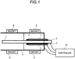
- FIG. 1 is a diagram illustrating a configuration of a cold cathode ionization vacuum gauge according to the embodiment of the present invention.
- the cold cathode ionization vacuum gauge according to the embodiment of the present invention includes an anode 1, a partition plate 2, a cathode 3, insulators 5, 5, anodes 7, 7, magnets 8, 9, and a controller 10.
- the anode 1 and the anode 7 are disposed in a face-to-face relationship with the cathode 3, in which the cathode 3 disposed in the face-to-face relationship with the two anodes 1 and 7 is configured as a common electrode having a same electric potential.
- the two anodes 7, 7 and the anode 1 are electrically insulated from each other by the insulators 5, 5 interposed therebetween, and the two anodes 7, 7 are thus interconnected.
- the anode 1, the anodes 7, 7 and the cathode 3 are connected to the controller 10, whereby the controller 10 controls the electric potentials of the anode 1, the anodes 7, 7 and the cathode 3.
- the magnets 8, 8 are provided outwardly of the cathode 3, corresponding to first discharge areas between the anode 1 and the cathode 3; and similarly the magnets 9, 9 are provided outwardly of the cathode 3, corresponding to second discharge areas between the anodes 7, 7 and the cathode 3.
- These couples of magnets 8, 8 and magnets 9, 9 have functions of applying magnetic fields to electrons released from the cathode 3 and thereby prompting the anodes 1 and 7, 7 to discharge the electricity.
- FIG. 2 An in-depth description of a contamination level diagnosis method for the cold cathode ionization vacuum gauge illustrated in FIG. 1 will hereinafter be made with reference to FIG. 2 .
- the cold cathode ionization vacuum gauge has a normal operation mode and a contamination diagnosing mode; the electricity is discharged by the controller 10 between the anode 1 and the cathode 3 in the normal operation mode; and a vacuum pressure is obtained by measuring a magnitude of an electric current flowing between the anode 1 and the cathode 3.
- anode 1 and the cathode 3 function as a pressure sensing means in the normal operation mode.
- step S1 the controller 10 causes the discharge between the anodes 7, 7 and the cathode 3, whereby the electrons are transferred and received between the anodes 7, 7 and the cathode 3.
- anodes 7, 7 and the cathode 3 function as the pressure sensing means in the contamination diagnosing mode.
- step S2 the controller 10 measures the magnitude of the current flowing between the the anodes 7, 7 and the cathode 3, and compares the thus-measured magnitude of the current with the magnitude of the current measured between the anode 1 and the cathode 3.
- step S3 the controller 10 determines whether a ratio or a difference between the electric current magnitudes compared in step S2 falls within a predetermined allowable range.
- the controller 10 when making a determination of falling within the allowable range, advances to step S4 and diagnoses the cold cathode ionization vacuum gauge as being clean; and the controller 10, whereas when making a determination of not falling within the allowable range, diverts to step S5 and diagnoses the cold cathode ionization vacuum gauge as being contaminated.
- the electrical discharge is not conducted in the normal operation mode in the second discharge area between the anode 7 and the cathode 3 but is conducted only in the contamination diagnosing mode, and hence the vacuum pressure can be measured by using the anode 7 and the cathode 3 that are lower in contamination level than the anode 1 and the cathode 3 configuring the first discharge area used in the normal operation mode.
- This method can cause a definite difference between the two current magnitudes set as the comparative targets in step S2 when the anode 1 and the cathode 3 configuring the first discharge area are contaminated.
- the contamination diagnosing mode may involve, in addition to discharging only the second discharge area in the description given above, discharging not only the second discharge area but also the first discharge area simultaneously.
- a switchover between the normal operation mode and the contamination diagnosing mode can entail adopting a method of switching off the discharge of any one of the first discharge area and the second discharge area, and thereafter switching on the other discharge area to be discharged.
- this method has such a problem that the switchover is enabled to be smoothly performed when a pressure of the discharge area is on the order of 10 -3 Pa but is disabled from being performed when the pressure of the discharge area is in ultrahigh vacuum (the pressure is equal to or lower than 10 -7 Pa) because the discharge of the other discharge area is hard to initiate.
- the discharger of the other discharge area is triggered by the discharge kept in one discharge area, i.e., triggered by transferring and receiving charged particles, thereby enabling a smooth initiation of the discharge of the other discharge area.
- the normal operation mode and the contamination diagnosing mode can be therefore smoothly switched over by switching off the discharge of one discharge area after initiating the discharge of the other discharge area.
- FIG. 3 is a circuit diagram illustrating a discharge switchover circuit 30 included by the controller 10 depicted in FIG. 1 .
- the discharge switchover circuit 30 includes switches SW1, SW2 and high-voltage relays r1, r2.
- one ends of switches SW1, SW2 and one ends of coils of the high-voltage relays r1, r2 are connected to a direct current power source DV.
- the other end of the switch SW1 is connected to the other end of the coil of the high-voltage relay r1; and the other end of the switch SW2 is connected to the other end of the coil of the high-voltage relay r2.
- Both of one ends of switching units of the high-voltage relays r1, r2 are supplied with a voltage as high as about, e.g., 2 kilo volts (kV).
- the other end of the switching unit of the high-voltage relay r1 is connected to the anode 1, while the other end of the switching unit of the high-voltage relay r2 is connected to the anode 7.
- FIG. 4 is a flowchart illustrating the contamination level diagnosis method using the discharge switchover circuit 30 depicted in FIG. 3 . The following discussion will describe in detail the contamination level diagnosis method using the discharge switchover circuit 30 with reference to FIG. 4 .
- step S1 the high voltage is supplied to the anode 1 by turning on the switch SW1 and thereby switching on the high-voltage relay r1 in the normal operation mode, whereby the discharge takes place between the anode 1 and the cathode 3.
- step S2 the high voltage is supplied to the anode 7 by turning on the switch SW2 and thereby switching on the high-voltage relay r2 while keeping the discharge in step S1, whereby the discharge is initiated between the anode 7 and the cathode 3.
- step S3 the discharge takes place only between the anode 7 and the cathode 3 by turning on the switch SW1 and thereby switching off the high-voltage relay r1 in order to enter the contamination diagnosing mode.
- the foregoing contamination level diagnosis method illustrated in FIG. 4 enables the smooth switchover between the normal operation mode and the contamination diagnosing mode by initiating the discharge between the anode 7 and the cathode 3 in the contamination diagnosing mode in a way that makes the use of the discharge state between the anode 1 and the cathode 3 in the normal operation mode.
- the discharge can be smoothly switched over by performing the same operation even when returned to the normal operation mode from the contamination diagnosing mode after diagnosing the contamination.
- the highly accurate diagnosis of the contamination level can be attained with the simple configuration by the simple method in such a way that the controller 10 separately uses the first discharge area and the second discharge area, provided in one vacuum gauge, in the normal operation mode and the contamination diagnosing mode.
- the controller 10 simply switches over the mode to the contamination diagnosing mode without stopping a vacuum apparatus installed with the present vacuum gauge, thereby enabling a determination of soundness of the vacuum gauge and a proper determination of a maintenance timing of the whole vacuum apparatus including the present vacuum gauge.
- FIG. 5 is a view illustrating a configuration of a hot cathode ionization vacuum gauge according to the embodiment of the present invention.
- the hot cathode ionization vacuum gauge according to the embodiment of the present invention includes a grid (anode) 11, a hot filament (cathode) 13, shields 15, 15, a first ion collector 17, a second ion collector 19, and a controller 20.
- the grid 11 and the hot filament 13 are disposed in the face-to-face relationship, and both of the first ion collector 17 and the second ion collector 19 are disposed on an opposite side to the grid 11 with the shields 15, 15 interposed therebetween.
- the grid 11, the hot filament 13, the first ion collector 17 and the second ion collector 19 are respectively connect to the controller 20, whereby the controller 20 controls the electric potentials of the grid 11, the hot filament 13, the first ion collector 17 and the second ion collector 19.
- a contamination level diagnosis method for the hot cathode ionization vacuum gauge illustrated in FIG. 5 will hereinafter be described in detail with reference to FIG. 6 .
- the electrons released from the hot filament 13 fly to the grid 11, during which the electrons impinge on gaseous molecules to thereby generate positive ions.
- the first ion collector 17 collects the positive ions in the normal operation mode, and a magnitude of an ion current is measured, thereby obtaining a vacuum pressure.
- the first ion collector 17 functions as the pressure sensing means in the normal operation mode.
- step S1 the controller 20 deflects a course of the positive ions by setting the first ion collector 17 in a positive potential state, and causes the second ion collector 19 to collect the positive ions.
- the second ion collector 19 functions as the pressure sensing means in the contamination diagnosing mode.
- step S2 the controller 20 measures the magnitude of the ion current of the positive ions collected by the second ion collector 19, and causes the first ion collector 17 to collect the positive ions, thereby making a comparison with the measured magnitude of the ion current.
- step S3 the controller 20 determines whether a ratio or a difference between the two magnitudes of the ion currents that are compared in step S2 falls within a predetermined allowable range.
- the controller 20 when making a determination of falling within the allowable range, advances to step S4 and diagnoses the hot cathode ionization vacuum gauge as being clean; and the controller 10, whereas when making a determination of not falling within the allowable range, diverts to step S5 and diagnoses the hot cathode ionization vacuum gauge as being contaminated.
- contaminants are deposited generally on a surface of the ion collector to produce an insulation film concomitantly with the collection of the positive ions, resulting in abnormality of a measured value of the ion current.
- the second ion collector 19 does not collect the ions in the normal operation mode but collects the ions only in the contamination diagnosing mode, and hence the vacuum pressure can be measured by using the second ion collector 19 exhibiting a lower contamination level than on the surface of the first ion collector 17 used in the normal operation mode.
- the definite difference can be thereby caused between the two magnitudes of the ion currents set as the comparative targets in step S2.
- the highly accurate diagnosis of the contamination level can be attained with the simple configuration by the simple method in such a way that the controller 20 separately uses the first ion collector 17 and the second ion collector 19, provided in one vacuum gauge, in the normal operation mode and the contamination diagnosing mode.
- the controller 20 simply switches over the mode to the contamination diagnosing mode without stopping the vacuum apparatus installed with the present vacuum gauge, thereby enabling the determination of the soundness of the vacuum gauge and the proper determination of the maintenance timing of the whole vacuum apparatus including the present vacuum gauge.
- the whole vacuum apparatus can be protected from more serious contamination by thus ensuring the soundness of the present vacuum gauge.
Landscapes
- General Physics & Mathematics (AREA)
- Physics & Mathematics (AREA)
- Chemical & Material Sciences (AREA)
- Analytical Chemistry (AREA)
- Health & Medical Sciences (AREA)
- Biomedical Technology (AREA)
- Engineering & Computer Science (AREA)
- Chemical Kinetics & Catalysis (AREA)
- Electrochemistry (AREA)
- Life Sciences & Earth Sciences (AREA)
- Biochemistry (AREA)
- General Health & Medical Sciences (AREA)
- Immunology (AREA)
- Pathology (AREA)
- Measuring Fluid Pressure (AREA)
Abstract
Description
- The present invention pertains to a vacuum gauge, and a method of diagnosing a contamination level of the vacuum gauge.
- For example, in a semiconductor manufacturing apparatus, a pressure within a chamber is measured by using a vacuum gauge, and it is, however, known that performance of an ionization vacuum gauge is deteriorated when used in a contaminated environment.
- Supposing that the ionization vacuum gauge does not indicate a normal value due to the deterioration, it follows that a large quantity of defective products are produced due to a progress of a semiconductor process under an abnormal condition. At this time, especially in the case of a fault mode in which the value displayed on the ionization vacuum gauge slightly deviates from the normal value, there arises a problem of not being aware of a fault in many cases.
Therefore, a determination of the deterioration has been tried to be made by some methods. Herein, there has hitherto been generally adopted a method of checking soundness of the vacuum gauge by calibrating the vacuum gauge through a test or an examination after removing the vacuum gauge from the semiconductor manufacturing apparatus, and this method has, however, a problem that an operating ratio of the semiconductor manufacturing apparatus drops down because of requiring a considerable length of time and a considerable cost. - A method of making the calibration by introducing a testing gas into a vacuum apparatus does not spread due to an anxiety for contaminating the vacuum apparatus, and due to involving a labor and a cost as well.
- Under such circumstances,
Patent Document 1 discloses a method of comparing values outputted from two independent vacuum degree detection units based on a same type of principle, and detecting abnormality of the vacuum gauge when a difference therebetween becomes larger than a preset value. - [Patent Literature 1] Japanese Patent Application Laid-Open Publication No.
2006-344738 - According to the method described in
Patent Document 1, when a fault occurs in one of the two vacuum degree detection units, the abnormality can be promptly detected. - However, when the fault occurs not in one but in both of the vacuum degree detection units such as these two vacuum degree detection units being contaminated to a same degree, there is no difference between the output values, resulting in a problem that the abnormality is not detected.
- This method is also a method of fitting two gauge heads and therefore requires a large space and two ports for fitting the vacuum gauges.
- It is an object of the present invention, which was devised to solve the problems described above, to provide a vacuum gauge capable of highly accurately diagnosing a contamination level of a vacuum gauge with a simple configuration, and a contamination level diagnosis method capable of highly accurately diagnosing the contamination level of the vacuum gauge in a simple procedure.
- For solving the problems described above, the present invention provides a vacuum gauge having a normal operation mode and a contamination diagnosing mode, including: first pressure sensing means to measure a vacuum pressure in the normal operation mode; second pressure sensing means to measure the vacuum pressure in the contamination diagnosing mode; and comparing means to compare a measurement value by the second pressure sensing means with a measurement value by the first pressure sensing means.
- For solving the problems described above, the present invention provides a vacuum gauge having a contamination diagnosing mode and a normal operation mode for measuring a vacuum pressure corresponding to a magnitude of an electric current to be detected, including: a first anode and a first cathode to transfer and receive charged particles forming the electric current; a second anode and a second cathode to transfer and receive the charged particles forming the electric current; and control means to measure the magnitude of the electric current flowing between the first anode and the first cathode by transferring and receiving the charged particles between the first anode and the first cathode in the normal operation mode, to measure the magnitude of the electric current flowing between the second anode and the second cathode by transferring and receiving the charged particles between the second anode and the second cathode in the contamination diagnosing mode, and to compare an electric current magnitude measured between the first anode and the first cathode with the foregoing measured electric current magnitude.
- For solving the problems described above, the present invention provides a vacuum gauge having a contamination diagnosing mode and a normal operation mode for measuring a vacuum pressure corresponding to a magnitude of an electric current to be detected, including: a first electrode to collect charged particles forming the electric current; a second electrode to collect the charged particles forming the electric current; and control means to measure the magnitude of the electric current by causing the first electrode to collect the charged particles in the normal operation mode, to measure the magnitude of the electric current by causing the second electrode to collect the charged particles in the contamination diagnosing mode, and to compare an electric current magnitude measured by causing the first electrode to collect the charged particles with the foregoing the electric current magnitude.
- For solving the problems described above, the present invention provides a contamination level diagnosis method for a vacuum gauge to measure a vacuumpressure corresponding to a magnitude of an electric current to be detected, including: a first step of transferring and receiving charged particles between a second anode and a second cathode being different from a first anode and a first cathode to transfer and receive the charged particles forming the electric current in a normal operation; a second step of measuring the magnitude of the electric current flowing between the second anode and the second cathode by transferring and receiving the charged particles, and comparing an electric current magnitude measured by transferring and receiving the charged particles between the first anode and the first cathode with the foregoing electric current magnitude; a third step of determining whether a ratio or a difference between the two electric current magnitudes compared in the second step falls within a predetermined range; and a fourth step of diagnosing the vacuum gauge to be clean when making a determination of falling within the predetermined range, and diagnosing the vacuum gauge to be contaminated when making the determination of not falling within the predetermined range in the third step.
- For solving the problems described above, the present invention provides a contamination level diagnosis method for a vacuum gauge to measure a vacuumpressure corresponding to a magnitude of an electric current to be detected, including: a first step of causing a second electrode to collect charged particles, the second electrode being different from a first electrode to collect the charged particles forming the electric current in the normal operation; a second step of measuring a magnitude of the electric current by causing the second electrode to collect the charged particles, and to compare an electric current magnitude measured by causing the first electrode to collect the charged particles with the foregoing electric current magnitude; a third step of determining whether a ratio or a difference between the two electric current magnitudes compared in the second step falls within a predetermined range; a fourth step of diagnosing the vacuum gauge to be clean when making a determination of falling within the predetermined range and diagnosing the vacuum gauge to be contaminated when making the determination of not falling within the predetermined range in the third step.
- According to the present invention, it is feasible to provide the vacuum gauge capable of highly accurately diagnosing the contamination level of the vacuum gauge with the simple configuration, and the contamination level diagnosis method capable of highly accurately diagnosing the contamination level of the vacuum gauge in the simple procedure.
-
-
FIG. 1 illustrates a view illustrating a cold cathode ionization vacuum gauge according to an embodiment of the present invention. -
FIG. 2 illustrates a flowchart illustrating a contamination level diagnosis method for the cold cathode ionization vacuum gauge illustrated inFIG. 1 . -
FIG. 3 illustrates a circuit diagram illustrating a configuration of adischarge switchover circuit 30 included by acontroller 10 depicted inFIG. 1 . -
FIG. 4 illustrates a flowchart illustrating the contamination level diagnosis method using thedischarge switchover circuit 30 illustrated inFIG. 3 . -
FIG. 5 illustrates a view illustrating a configuration of a hot cathode ionization vacuum gauge according to the embodiment of the present invention. -
FIG. 6 illustrates a flowchart illustrating a contamination level diagnosis method for the hot cathode ionization vacuum gauge illustrated inFIG. 5 . - An embodiment of the present invention will hereinafter be described in detail with reference to the drawings. Note that the same reference numerals and symbols represent the same or corresponding components in the drawings throughout.
-
FIG. 1 is a diagram illustrating a configuration of a cold cathode ionization vacuum gauge according to the embodiment of the present invention. As illustrated inFIG. 1 , the cold cathode ionization vacuum gauge according to the embodiment of the present invention includes ananode 1, apartition plate 2, acathode 3,insulators anodes magnets controller 10. Herein, theanode 1 and theanode 7 are disposed in a face-to-face relationship with thecathode 3, in which thecathode 3 disposed in the face-to-face relationship with the twoanodes - The two
anodes anode 1 are electrically insulated from each other by theinsulators anodes anode 1, theanodes cathode 3 are connected to thecontroller 10, whereby thecontroller 10 controls the electric potentials of theanode 1, theanodes cathode 3. - The
magnets cathode 3, corresponding to first discharge areas between theanode 1 and thecathode 3; and similarly themagnets cathode 3, corresponding to second discharge areas between theanodes cathode 3. These couples ofmagnets magnets cathode 3 and thereby prompting theanodes - An in-depth description of a contamination level diagnosis method for the cold cathode ionization vacuum gauge illustrated in
FIG. 1 will hereinafter be made with reference toFIG. 2 . - To start with, a premise is that the cold cathode ionization vacuum gauge has a normal operation mode and a contamination diagnosing mode; the electricity is discharged by the
controller 10 between theanode 1 and thecathode 3 in the normal operation mode; and a vacuum pressure is obtained by measuring a magnitude of an electric current flowing between theanode 1 and thecathode 3. - It therefore follows that the
anode 1 and thecathode 3 function as a pressure sensing means in the normal operation mode. - On the other hand, in the contamination diagnosing mode for diagnosing the contamination level, at first, in step S1, the
controller 10 causes the discharge between theanodes cathode 3, whereby the electrons are transferred and received between theanodes cathode 3. - Accordingly, it follows that the
anodes cathode 3 function as the pressure sensing means in the contamination diagnosing mode. - Next in step S2, the
controller 10 measures the magnitude of the current flowing between the theanodes cathode 3, and compares the thus-measured magnitude of the current with the magnitude of the current measured between theanode 1 and thecathode 3. - Subsequently in step S3, the
controller 10 determines whether a ratio or a difference between the electric current magnitudes compared in step S2 falls within a predetermined allowable range. - The
controller 10, when making a determination of falling within the allowable range, advances to step S4 and diagnoses the cold cathode ionization vacuum gauge as being clean; and thecontroller 10, whereas when making a determination of not falling within the allowable range, diverts to step S5 and diagnoses the cold cathode ionization vacuum gauge as being contaminated. - According to the foregoing contamination level diagnosis method illustrated in
FIG. 2 , the electrical discharge is not conducted in the normal operation mode in the second discharge area between theanode 7 and thecathode 3 but is conducted only in the contamination diagnosing mode, and hence the vacuum pressure can be measured by using theanode 7 and thecathode 3 that are lower in contamination level than theanode 1 and thecathode 3 configuring the first discharge area used in the normal operation mode. - This method can cause a definite difference between the two current magnitudes set as the comparative targets in step S2 when the
anode 1 and thecathode 3 configuring the first discharge area are contaminated. - Note that the contamination diagnosing mode may involve, in addition to discharging only the second discharge area in the description given above, discharging not only the second discharge area but also the first discharge area simultaneously.
- Herein, a switchover between the normal operation mode and the contamination diagnosing mode can entail adopting a method of switching off the discharge of any one of the first discharge area and the second discharge area, and thereafter switching on the other discharge area to be discharged.
- However, this method has such a problem that the switchover is enabled to be smoothly performed when a pressure of the discharge area is on the order of 10-3Pa but is disabled from being performed when the pressure of the discharge area is in ultrahigh vacuum (the pressure is equal to or lower than 10-7Pa) because the discharge of the other discharge area is hard to initiate.
- Such being the case, when carrying out the switchover, the discharge of one discharge area is kept, while the discharge of the other discharge area is initiated.
- With the means such as this, the discharger of the other discharge area is triggered by the discharge kept in one discharge area, i.e., triggered by transferring and receiving charged particles, thereby enabling a smooth initiation of the discharge of the other discharge area.
- The normal operation mode and the contamination diagnosing mode can be therefore smoothly switched over by switching off the discharge of one discharge area after initiating the discharge of the other discharge area.
- An in-depth description of the embodiment for attaining the switchover between the normal operation mode and the contamination diagnosing mode, will hereinafter be made.
-
FIG. 3 is a circuit diagram illustrating adischarge switchover circuit 30 included by thecontroller 10 depicted inFIG. 1 . As illustrated inFIG. 3 , thedischarge switchover circuit 30 includes switches SW1, SW2 and high-voltage relays r1, r2. - Herein, one ends of switches SW1, SW2 and one ends of coils of the high-voltage relays r1, r2 are connected to a direct current power source DV. The other end of the switch SW1 is connected to the other end of the coil of the high-voltage relay r1; and the other end of the switch SW2 is connected to the other end of the coil of the high-voltage relay r2. Both of one ends of switching units of the high-voltage relays r1, r2 are supplied with a voltage as high as about, e.g., 2 kilo volts (kV). The other end of the switching unit of the high-voltage relay r1 is connected to the
anode 1, while the other end of the switching unit of the high-voltage relay r2 is connected to theanode 7. -
FIG. 4 is a flowchart illustrating the contamination level diagnosis method using thedischarge switchover circuit 30 depicted inFIG. 3 . The following discussion will describe in detail the contamination level diagnosis method using thedischarge switchover circuit 30 with reference toFIG. 4 . - To begin with, in step S1, the high voltage is supplied to the
anode 1 by turning on the switch SW1 and thereby switching on the high-voltage relay r1 in the normal operation mode, whereby the discharge takes place between theanode 1 and thecathode 3. - Next, in step S2, the high voltage is supplied to the
anode 7 by turning on the switch SW2 and thereby switching on the high-voltage relay r2 while keeping the discharge in step S1, whereby the discharge is initiated between theanode 7 and thecathode 3. - In step S3, the discharge takes place only between the
anode 7 and thecathode 3 by turning on the switch SW1 and thereby switching off the high-voltage relay r1 in order to enter the contamination diagnosing mode. - The foregoing contamination level diagnosis method illustrated in
FIG. 4 enables the smooth switchover between the normal operation mode and the contamination diagnosing mode by initiating the discharge between theanode 7 and thecathode 3 in the contamination diagnosing mode in a way that makes the use of the discharge state between theanode 1 and thecathode 3 in the normal operation mode. The discharge can be smoothly switched over by performing the same operation even when returned to the normal operation mode from the contamination diagnosing mode after diagnosing the contamination. - Through the operation described above, according to the cold cathode ionization vacuum gauge and the contamination level diagnosis method for the cold cathode ionization vacuum gauge according to the embodiment of the present invention illustrated in
FIG. 1 , the highly accurate diagnosis of the contamination level can be attained with the simple configuration by the simple method in such a way that thecontroller 10 separately uses the first discharge area and the second discharge area, provided in one vacuum gauge, in the normal operation mode and the contamination diagnosing mode. - According to the cold cathode ionization vacuum gauge described above, the
controller 10 simply switches over the mode to the contamination diagnosing mode without stopping a vacuum apparatus installed with the present vacuum gauge, thereby enabling a determination of soundness of the vacuum gauge and a proper determination of a maintenance timing of the whole vacuum apparatus including the present vacuum gauge. - It follows that the whole vacuum apparatus can be protected from serious contamination by thus ensuring the soundness of the present vacuum gauge.
-
FIG. 5 is a view illustrating a configuration of a hot cathode ionization vacuum gauge according to the embodiment of the present invention. As illustrated inFIG. 5 , the hot cathode ionization vacuum gauge according to the embodiment of the present invention includes a grid (anode) 11, a hot filament (cathode) 13, shields 15, 15, afirst ion collector 17, asecond ion collector 19, and acontroller 20. - Herein, the
grid 11 and thehot filament 13 are disposed in the face-to-face relationship, and both of thefirst ion collector 17 and thesecond ion collector 19 are disposed on an opposite side to thegrid 11 with theshields grid 11, thehot filament 13, thefirst ion collector 17 and thesecond ion collector 19 are respectively connect to thecontroller 20, whereby thecontroller 20 controls the electric potentials of thegrid 11, thehot filament 13, thefirst ion collector 17 and thesecond ion collector 19. - A contamination level diagnosis method for the hot cathode ionization vacuum gauge illustrated in
FIG. 5 will hereinafter be described in detail with reference toFIG. 6 . - In the hot cathode ionization vacuum gauge described above, the electrons released from the
hot filament 13 fly to thegrid 11, during which the electrons impinge on gaseous molecules to thereby generate positive ions. In the vacuum gauge having the normal operation mode and the contamination diagnosing mode, thefirst ion collector 17 collects the positive ions in the normal operation mode, and a magnitude of an ion current is measured, thereby obtaining a vacuum pressure. - Accordingly, the
first ion collector 17 functions as the pressure sensing means in the normal operation mode. - On the other hand, in the contamination diagnosing mode for diagnosing the contamination level, at first in step S1, the
controller 20 deflects a course of the positive ions by setting thefirst ion collector 17 in a positive potential state, and causes thesecond ion collector 19 to collect the positive ions. - Accordingly, the
second ion collector 19 functions as the pressure sensing means in the contamination diagnosing mode. - Next, in step S2, the
controller 20 measures the magnitude of the ion current of the positive ions collected by thesecond ion collector 19, and causes thefirst ion collector 17 to collect the positive ions, thereby making a comparison with the measured magnitude of the ion current. - Subsequently in step S3, the
controller 20 determines whether a ratio or a difference between the two magnitudes of the ion currents that are compared in step S2 falls within a predetermined allowable range. - The
controller 20, when making a determination of falling within the allowable range, advances to step S4 and diagnoses the hot cathode ionization vacuum gauge as being clean; and thecontroller 10, whereas when making a determination of not falling within the allowable range, diverts to step S5 and diagnoses the hot cathode ionization vacuum gauge as being contaminated. - Note that contaminants are deposited generally on a surface of the ion collector to produce an insulation film concomitantly with the collection of the positive ions, resulting in abnormality of a measured value of the ion current.
- According to the foregoing contamination level diagnosis method illustrated in
FIG. 6 , thesecond ion collector 19 does not collect the ions in the normal operation mode but collects the ions only in the contamination diagnosing mode, and hence the vacuum pressure can be measured by using thesecond ion collector 19 exhibiting a lower contamination level than on the surface of thefirst ion collector 17 used in the normal operation mode. - When the
first ion collector 17 is contaminated, the definite difference can be thereby caused between the two magnitudes of the ion currents set as the comparative targets in step S2. - Through the operation described above, according to the hot cathode ionization vacuum gauge and the contamination level diagnosis method for the hot cathode ionization vacuum gauge according to the embodiment of the present invention illustrated in
FIG. 5 , the highly accurate diagnosis of the contamination level can be attained with the simple configuration by the simple method in such a way that thecontroller 20 separately uses thefirst ion collector 17 and thesecond ion collector 19, provided in one vacuum gauge, in the normal operation mode and the contamination diagnosing mode. - By the hot cathode ionization vacuum gauge described above, the
controller 20 simply switches over the mode to the contamination diagnosing mode without stopping the vacuum apparatus installed with the present vacuum gauge, thereby enabling the determination of the soundness of the vacuum gauge and the proper determination of the maintenance timing of the whole vacuum apparatus including the present vacuum gauge. - The whole vacuum apparatus can be protected from more serious contamination by thus ensuring the soundness of the present vacuum gauge.
- Note that although describing so far the embodiments of the cold cathode ionization vacuum gauge and the hot cathode ionization vacuum gauge, the present invention is considered applicable to different types of vacuum gauges.
-
- 1, 7
- anode
- 3
- cathode
- 8, 9
- magnet
- 10, 20
- controller
- 11
- grid (anode)
- 13
- hot filament (cathode)
- 17
- first ion collector
- 19
- second ion collector
- 30
- discharge switchover circuit
Claims (10)
- A vacuum gauge having a normal operation mode and a contamination diagnosing mode, comprising:first pressure sensing means to measure a vacuum pressure in the normal operation mode;second pressure sensing means to measure the vacuum pressure in the contamination diagnosing mode; andcomparing means to compare a measurement value by the second pressure sensingmeans with a measurement value by the first pressure sensing means.
- A vacuum gauge having a contamination diagnosing mode and a normal operation mode for measuring a vacuum pressure corresponding to a magnitude of an electric current to be detected, comprising:a first anode and a first cathode to transfer and receive charged particles forming the electric current;a second anode and a second cathode to transfer and receive the charged particles forming the electric current; andcontrol means to measure the magnitude of the electric current flowing between the first anode and the first cathode by transferring and receiving the charged particles between the first anode and the first cathode in the normal operation mode, to measure the magnitude of the electric current flowing between the second anode and the second cathode by transferring and receiving the charged particles between the second anode and the second cathode in the contamination diagnosing mode, and to compare an electric current magnitude measured between the first anode and the first cathode with the foregoing measured electric current magnitude.
- The vacuum gauge according to claim 2, further comprising magnetic field applying means to apply magnetic fields to the charged particles transferred and received between the first anode and the first cathode and to the charged particles transferred and received between the second anode and the second cathode.
- The vacuum gauge according to claim 2 or 3, wherein the first cathode and the second cathode are configured as common electrodes having a same electric potential.
- The vacuum gauge according to claim 2, wherein the control means, when switching over the normal operation mode and the contamination diagnosing mode, starts transferring and receiving the charged particles in the mode after the switchover while keeping the transfer and the reception of the charged particles in the mode before the switchover.
- A vacuum gauge having a contamination diagnosing mode and a normal operation mode for measuring a vacuum pressure corresponding to a magnitude of an electric current to be detected, comprising:a first electrode to collect charged particles forming the electric current;a second electrode to collect the charged particles forming the electric current; andcontrol means to measure the magnitude of the electric current by causing the first electrode to collect the charged particles in the normal operation mode, to measure the magnitude of the electric current by causing the second electrode to collect the charged particles in the contamination diagnosing mode, and to compare an electric current magnitude measured by causing the first electrode to collect the charged particles with the foregoing the electric current magnitude.
- The vacuum gauge according to claim 6, further comprising an anode and a cathode for generating the charged particles.
- A contamination level diagnosis method for a vacuum gauge to measure a vacuum pressure corresponding to a magnitude of an electric current to be detected, comprising:a first step of transferring and receiving charged particles between a second anode and a second cathode being different from a first anode and a first cathode to transfer and receive the charged particles forming the electric current in a normal operation;a second step of measuring the magnitude of the electric current flowing between the second anode and the second cathode by transferring and receiving the charged particles, and comparing an electric current magnitude measured by transferring and receiving the charged particles between the first anode and the first cathode with the foregoing electric current magnitude;a third step of determining whether a ratio or a difference between the two electric current magnitudes compared in the second step falls within a predetermined range; anda fourth step of diagnosing the vacuum gauge to be clean when making a determination of falling within the predetermined range, and diagnosing the vacuum gauge to be contaminated when making the determination of not falling within the predetermined range in the third step.
- The contamination level diagnosis method according to claim 8, wherein the first step includes:a step of starting the transfer and the reception of the charged particles between the second anode and the second cathode while keeping the transfer and the reception of the charged particles in the normal operation; anda step of finishing the transfer and the reception of the charged particles between the first anode and the first cathode after starting the transfer and the reception of the charged particles between the second anode and the second cathode.
- A contamination level diagnosis method for a vacuum gauge to measure a vacuum pressure corresponding to a magnitude of an electric current to be detected, comprising:a first step of causing a second electrode to collect charged particles, the second electrode being different from a first electrode to collect the charged particles forming the electric current in the normal operation;a second step of measuring a magnitude of the electric current by causing the second electrode to collect the charged particles, and to compare an electric current magnitude measured by causing the first electrode to collect the charged particles with the foregoing electric current magnitude;a third step of determining whether a ratio or a difference between the two electric current magnitudes compared in the second step falls within a predetermined range;a fourth step of diagnosing the vacuum gauge to be clean when making a determination of falling within the predetermined range and diagnosing the vacuum gauge to be contaminated when making the determination of not falling within the predetermined range in the third step.
Applications Claiming Priority (3)
| Application Number | Priority Date | Filing Date | Title |
|---|---|---|---|
| JP2014155291 | 2014-07-30 | ||
| JP2015112612A JP2016033509A (en) | 2014-07-30 | 2015-06-02 | Vacuum gauge and contamination diagnosis method |
| PCT/JP2015/071563 WO2016017720A1 (en) | 2014-07-30 | 2015-07-29 | Vacuum gauge and contamination diagnosis method |
Publications (2)
| Publication Number | Publication Date |
|---|---|
| EP3196622A1 true EP3196622A1 (en) | 2017-07-26 |
| EP3196622A4 EP3196622A4 (en) | 2018-07-04 |
Family
ID=55217617
Family Applications (1)
| Application Number | Title | Priority Date | Filing Date |
|---|---|---|---|
| EP15828187.3A Withdrawn EP3196622A4 (en) | 2014-07-30 | 2015-07-29 | Vacuum gauge and contamination diagnosis method |
Country Status (4)
| Country | Link |
|---|---|
| US (1) | US10094728B2 (en) |
| EP (1) | EP3196622A4 (en) |
| JP (1) | JP2016033509A (en) |
| WO (1) | WO2016017720A1 (en) |
Families Citing this family (4)
| Publication number | Priority date | Publication date | Assignee | Title |
|---|---|---|---|---|
| CN109075010B (en) * | 2016-05-02 | 2020-09-15 | 万机仪器公司 | Cold cathode ionization vacuum gauge and method for measuring pressure |
| JP7195949B2 (en) * | 2019-01-24 | 2022-12-26 | 株式会社アルバック | Hot cathode ionization vacuum gauge, pressure measurement system equipped with hot cathode ionization vacuum gauge, and pressure measurement method using hot cathode ionization vacuum gauge |
| KR102703191B1 (en) * | 2019-09-20 | 2024-09-04 | 인피콘 아크티엔게젤샤프트 | Method for determining pressure and pressure sensor |
| TW202405424A (en) * | 2022-04-19 | 2024-02-01 | 美商英福康公司 | Partial pressure gauge assembly for process contaminant detection using photoionization and associated method |
Family Cites Families (7)
| Publication number | Priority date | Publication date | Assignee | Title |
|---|---|---|---|---|
| JP3707522B2 (en) * | 1998-08-21 | 2005-10-19 | 日産自動車株式会社 | Evaporative fuel processor diagnostic device |
| JP3935653B2 (en) * | 2000-02-04 | 2007-06-27 | 株式会社ニデック | Perfusion suction device |
| DE102005010716A1 (en) * | 2005-03-09 | 2006-09-14 | Inficon Gmbh | Cold cathode pressure sensor |
| JP2006344738A (en) | 2005-06-08 | 2006-12-21 | Renesas Technology Corp | Manufacturing method for semiconductor device |
| US7768267B2 (en) * | 2007-07-11 | 2010-08-03 | Brooks Automation, Inc. | Ionization gauge with a cold electron source |
| JP5370329B2 (en) | 2010-09-30 | 2013-12-18 | 株式会社デンソー | Sensor diagnostic device |
| US9588004B2 (en) * | 2014-11-07 | 2017-03-07 | Mks Instruments, Inc. | Long lifetime cold cathode ionization vacuum gauge design |
-
2015
- 2015-06-02 JP JP2015112612A patent/JP2016033509A/en active Pending
- 2015-07-29 US US15/329,986 patent/US10094728B2/en not_active Expired - Fee Related
- 2015-07-29 WO PCT/JP2015/071563 patent/WO2016017720A1/en not_active Ceased
- 2015-07-29 EP EP15828187.3A patent/EP3196622A4/en not_active Withdrawn
Also Published As
| Publication number | Publication date |
|---|---|
| US10094728B2 (en) | 2018-10-09 |
| WO2016017720A1 (en) | 2016-02-04 |
| JP2016033509A (en) | 2016-03-10 |
| US20170254714A1 (en) | 2017-09-07 |
| EP3196622A4 (en) | 2018-07-04 |
Similar Documents
| Publication | Publication Date | Title |
|---|---|---|
| CN107005065B (en) | Battery pack system having a battery pack designed to supply electrical energy to a high-voltage network and having a measuring device for measuring at least one insulation resistance of the battery pack | |
| JP6252439B2 (en) | Abnormality detection method and abnormality detection device for secondary battery | |
| JP5071747B2 (en) | Secondary battery inspection device, secondary battery inspection method, secondary battery manufacturing method | |
| US10094728B2 (en) | Vacuum gauge and contamination diagnosis method | |
| EP2389702B1 (en) | Arrangement and method for monitoring galvanic isolation of fuel cell device | |
| JP2015117995A (en) | Charge / discharge test equipment for detecting poor contact | |
| US9606162B2 (en) | Insulation inspection method and insulation inspection apparatus | |
| KR20140026300A (en) | Method and apparatus for the measurement of a resistance of a switching contact of an electrical circuit breaker | |
| JP6778617B2 (en) | Systems and methods for distinguishing short circuits in batteries | |
| EP3480612A1 (en) | Device and method for measuring insulation resistance of battery pack by using negative electrode relay | |
| CN109219754A (en) | Apparatus and method for detecting failure of battery pack | |
| JP2011058803A (en) | Test device and power source device | |
| CN109765475A (en) | The reverse-biased pilot system of high temperature and humidity and test method for semiconductor devices | |
| JP2010197132A (en) | Vacuum circuit breaker vacuum tester | |
| JP2017223580A (en) | Charge / discharge device | |
| CN107356849B (en) | Partial discharge detection device and method for support insulator in gas insulated switchgear | |
| KR101497585B1 (en) | Rectifier module control device of cathodic protection system for condenser | |
| KR101165298B1 (en) | The partial discharge measuring method for power cable in nuclear power plant using vlf voltage source and hfctpd device | |
| US20200191881A1 (en) | Ground fault detection device | |
| US20240006174A1 (en) | Method for Controlling Mass Spectrometer | |
| US11740271B2 (en) | Insulation resistance monitoring device | |
| CN106646144A (en) | Partial discharge detection method of electric power insulation material | |
| US20060063284A1 (en) | DC bias voltage measurement circuit and plasma CVD apparatus comprising the same | |
| CN108831821B (en) | Quadrupole mass spectrometer and its judgment method of sensitivity decline | |
| CN114910810A (en) | Fuel cell detection apparatus, method and system |
Legal Events
| Date | Code | Title | Description |
|---|---|---|---|
| PUAI | Public reference made under article 153(3) epc to a published international application that has entered the european phase |
Free format text: ORIGINAL CODE: 0009012 |
|
| 17P | Request for examination filed |
Effective date: 20170126 |
|
| AK | Designated contracting states |
Kind code of ref document: A1 Designated state(s): AL AT BE BG CH CY CZ DE DK EE ES FI FR GB GR HR HU IE IS IT LI LT LU LV MC MK MT NL NO PL PT RO RS SE SI SK SM TR |
|
| AX | Request for extension of the european patent |
Extension state: BA ME |
|
| DAV | Request for validation of the european patent (deleted) | ||
| DAX | Request for extension of the european patent (deleted) | ||
| RIC1 | Information provided on ipc code assigned before grant |
Ipc: G01L 27/00 20060101AFI20180220BHEP Ipc: G01L 21/32 20060101ALI20180220BHEP Ipc: G01L 21/34 20060101ALI20180220BHEP |
|
| A4 | Supplementary search report drawn up and despatched |
Effective date: 20180601 |
|
| RIC1 | Information provided on ipc code assigned before grant |
Ipc: G01L 27/00 20060101AFI20180525BHEP Ipc: G01L 21/34 20060101ALI20180525BHEP Ipc: G01L 21/32 20060101ALI20180525BHEP |
|
| 17Q | First examination report despatched |
Effective date: 20190430 |
|
| GRAP | Despatch of communication of intention to grant a patent |
Free format text: ORIGINAL CODE: EPIDOSNIGR1 |
|
| INTG | Intention to grant announced |
Effective date: 20191031 |
|
| STAA | Information on the status of an ep patent application or granted ep patent |
Free format text: STATUS: THE APPLICATION IS DEEMED TO BE WITHDRAWN |
|
| 18D | Application deemed to be withdrawn |
Effective date: 20200311 |