EP3196620A1 - Compact or miniature high temperature differential pressure sensor capsule - Google Patents
Compact or miniature high temperature differential pressure sensor capsule Download PDFInfo
- Publication number
- EP3196620A1 EP3196620A1 EP17151684.2A EP17151684A EP3196620A1 EP 3196620 A1 EP3196620 A1 EP 3196620A1 EP 17151684 A EP17151684 A EP 17151684A EP 3196620 A1 EP3196620 A1 EP 3196620A1
- Authority
- EP
- European Patent Office
- Prior art keywords
- pressure sensor
- differential pressure
- sensor
- diaphragm
- pedestal
- Prior art date
- Legal status (The legal status is an assumption and is not a legal conclusion. Google has not performed a legal analysis and makes no representation as to the accuracy of the status listed.)
- Withdrawn
Links
Images


Classifications
-
- G—PHYSICS
- G01—MEASURING; TESTING
- G01L—MEASURING FORCE, STRESS, TORQUE, WORK, MECHANICAL POWER, MECHANICAL EFFICIENCY, OR FLUID PRESSURE
- G01L13/00—Devices or apparatus for measuring differences of two or more fluid pressure values
- G01L13/06—Devices or apparatus for measuring differences of two or more fluid pressure values using electric or magnetic pressure-sensitive elements
-
- G—PHYSICS
- G01—MEASURING; TESTING
- G01L—MEASURING FORCE, STRESS, TORQUE, WORK, MECHANICAL POWER, MECHANICAL EFFICIENCY, OR FLUID PRESSURE
- G01L13/00—Devices or apparatus for measuring differences of two or more fluid pressure values
- G01L13/02—Devices or apparatus for measuring differences of two or more fluid pressure values using elastically-deformable members or pistons as sensing elements
- G01L13/025—Devices or apparatus for measuring differences of two or more fluid pressure values using elastically-deformable members or pistons as sensing elements using diaphragms
- G01L13/026—Devices or apparatus for measuring differences of two or more fluid pressure values using elastically-deformable members or pistons as sensing elements using diaphragms involving double diaphragm
-
- G—PHYSICS
- G01—MEASURING; TESTING
- G01L—MEASURING FORCE, STRESS, TORQUE, WORK, MECHANICAL POWER, MECHANICAL EFFICIENCY, OR FLUID PRESSURE
- G01L19/00—Details of, or accessories for, apparatus for measuring steady or quasi-steady pressure of a fluent medium insofar as such details or accessories are not special to particular types of pressure gauges
- G01L19/0007—Fluidic connecting means
- G01L19/0046—Fluidic connecting means using isolation membranes
-
- G—PHYSICS
- G01—MEASURING; TESTING
- G01L—MEASURING FORCE, STRESS, TORQUE, WORK, MECHANICAL POWER, MECHANICAL EFFICIENCY, OR FLUID PRESSURE
- G01L19/00—Details of, or accessories for, apparatus for measuring steady or quasi-steady pressure of a fluent medium insofar as such details or accessories are not special to particular types of pressure gauges
- G01L19/0061—Electrical connection means
- G01L19/0084—Electrical connection means to the outside of the housing
-
- G—PHYSICS
- G01—MEASURING; TESTING
- G01L—MEASURING FORCE, STRESS, TORQUE, WORK, MECHANICAL POWER, MECHANICAL EFFICIENCY, OR FLUID PRESSURE
- G01L19/00—Details of, or accessories for, apparatus for measuring steady or quasi-steady pressure of a fluent medium insofar as such details or accessories are not special to particular types of pressure gauges
- G01L19/04—Means for compensating for effects of changes of temperature, i.e. other than electric compensation
Definitions
- This invention relates to pressure sensors.
- this invention relates to robust, extremely compact differential pressure sensors.
- Pressure transmitters are commonly used in industrial processes to measure and monitor pressures of various industrial process fluids such as vapors and gasses of engines and other power sources.
- Differential pressure transmitters generally include a pair of process fluid inputs which are coupled to a differential pressure sensor in the transmitter that responds to a difference in pressure between the two inputs.
- Differential pressure transmitters typically include a differential pressure sensor coupled to a pair of isolator diaphragms. The isolator diaphragms are positioned at the process fluid inlets and isolate the differential pressure sensor from process fluids being sensed. Pressure is transferred from the process fluid to the differential pressure sensor through a thermally stable fill fluid in a passageway extending from the isolator diaphragms to the differential pressure sensor.
- a differential pressure sensor includes a body having a first end, a second end, and a wall.
- the first and second ends include isolator diaphragms connected to external first and second process fluid inlets.
- a MEMS pressure sensor including a pressure sensing diaphragm inside the cylinder has first and second sides coupled to the first and second isolator diaphragms by first and second fill fluid volumes. Sensor elements on the diaphragm are configured to provide, via associated sensor circuitry, an indication of deflection due to pressure differences between the first and second fill volumes. Electrical and fill fluid connections to the differential pressure sensor are through radial connections in the cylinder wall.
- FIG. 1 A cross-section of a microelectromechanical system (MEMS) pressure sensor is shown in FIG. 1 .
- Pressure sensor 10 may comprise a single crystal silicon wafer 12 secured to silicon backing wafer 14 along bond line 16. The cavity in wafer 12 may form diaphragm D with bottom surface 24. Dielectric coating 18 and sensing elements 20 with associated circuitry (not shown) on top surface 22 of diaphragm D may detect deflection of diaphragm D due to a pressure P thereby indicating and measuring a pressure change. Sensing elements 20 may be piezoelectric, piezoresistive or other sensing means known in the art.
- MEMS pressure sensor 10 of FIG. 1 may be the pressure sensor used in embodiments of the differential pressure sensor under pressures P1 and P2 shown in FIGS. 2 and 3 and described below.
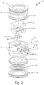
- FIG. 2 is an exploded view of differential pressure sensing capsule 30 according to an embodiment of the invention.
- Capsule 30 has a compact cylindrical body with metal isolation diaphragms 36 and 42 on each end of the capsule.
- Capsule 30 may be a compact package with fill fluid connections 54 and 55 and electrical connections 56 exiting the capsule in radial directions, thereby adding to the compactness of the device.
- External components of capsule 30 may include header 32, isolator plates 34 and 40, isolator diaphragms 36 and 42 and weld rings 38 and 44 all formed from stainless steel.
- Internal components of capsule 30 may include MEMS pressure sensor 10 (for example, as described above with respect to FIG.
- FIG. 1 shows ULTEM amorphous thermoplastic polyetherimid (PEI) resin spacer 46, ULTEM chamber 58, Pyrex pedestal 50, and Kovar pedestal 52 (shown in FIG. 3 ).
- Fill fluid connections 54 and 55 may be nickel or nickel alloy tubes brazed to stainless steel header 32.
- Electrical connections 56 may be gold plated Inconel wires in a glass ceramic seal.
- FIG. 2 shows a cylindrical capsule, the shape may have any form including square, hexagonal, or others that fit the needs of the system, including custom shapes that are not necessarily regular polygons.
- a cross-section of differential pressure sensing capsule 30 is shown in FIG. 3 .
- All metal components are 316 L stainless steel in an exemplary embodiment. All the external joints in the capsule may be joined by TIG welds.
- Sensor 10 may be mounted on a two-part, thermally stable pedestal comprising Pyrex pedestal 50 on Kovar pedestal 52. Sensor 10 may be attached to Pyrex pedestal 50 by anodic bonding. Anodic bonding is the process of applying a pressure to the joint and applying an electric field across the joint at an elevated temperature to assist ionic diffusion to form a bond.
- Pyrex pedestal 50 may be attached to Kovar pedestal 52 by brazing.
- Kovar pedestal 52 may be attached to header 32 by brazing.
- the coefficients of thermal expansion (CTE) of the internal components may be designed to minimize their dimensional change during a change in temperature and to minimize the joint integrity where Kovar pedestal 52 is joined to header 32.
- the CTEs of silicon, Pyrex, Kovar, and 316 L stainless steel are 3x10 -6 m/m°K, 4x10 -6 m/m o K, 5.1x10 -6 m/m o K and 16x10 -6 m/m°K respectively.
- the low CTE of the overall sensor stack minimizes the volume change of interior components in the fill fluid volume during temperature excursions, thereby increasing the accuracy of the differential pressure measurements.
- Fill fluids 60 and 62 are indicated in FIG. 3 by dark shading. After capsule 30 is filled with fill fluids 60 and 62 through nickel or nickel alloy fill tubes 54 and 55, nickel or nickel alloy fill tubes 54 and 55 may be crimped and spot welded to seal the fluid chambers as indicated by " /" in FIG. 3 .
- Process fluid pressure P1 may deflect isolator diaphragm 36 which raises pressure in fill fluid 60 under isolator diaphragm 36.
- Fill fluid 60 is fluidly connected to top surface 22 ( FIG. 1 ) of sensor 10 which causes diaphragm D ( FIG. 1 ) of sensor 10 to deflect, thereby generating a signal from sensors 20 ( FIG. 1 ).
- Process fluid pressure P2 may deflect isolator diaphragm 42 which raises pressure in fill fluid 62 behind isolator diaphragm 42.
- Isolator diaphragm 42 is fluidly connected to bottom surface 24 ( FIG. 1 ) of sensor 10 which causes diaphragm D ( FIG. 1 ) to deflect depending on the difference in pressures P1 and P2, thereby generating a signal from sensors 20 ( FIG. 1 ).
- the volumes of fill fluids 60 and 62 are equally matched.
- a circular depression in isolator plate 40 creates fluid chamber 70 that may be designed to allow the volume of fill fluid 62 fluidly connected to bottom surface 24 ( FIG. 1 ) of sensor 10 to match the volume of fill fluid 60 fluidly connected to top surface 22 ( FIG. 1 ) of sensor 10, thereby minimizing any error in thermally induced pressure in fill fluid volumes 60 and 62.
- Fill fluids used in differential pressure sensor 30 are thermally stable fluids with low CTE values.
- a fill fluid may be an oxidative and thermally stable fluid, such as DURATHERM with a CTE of 0.1011%/°C.
- the diameter and height of the sensing capsule are from about 10.2 mm to about 17.8 mm.
- the operating temperature is from about -55°C to 225°C.
- higher operating pressures may be achieved by different diaphragm thicknesses and the maximum operating pressure is about 13.8 MPa.
- a differential pressure sensor may include: a body with a first end, a second end, and a wall, wherein the first end and the second end are isolator diaphragms connected to first and second process fluid inlets; a MEMS pressure sensor with a pressure sensing diaphragm inside the cylinder with first and second sides coupled to the first and second isolator diaphragms via first and second fill fluid volumes; and sensor elements on the diaphragm that provide, with associated sensor circuitry, an indication of deflection of the diaphragm as a result of pressure differences between the first and second process fluid volumes, and electrical connections and fill fluid connections to the pressure sensor through radial connections in the wall of the body.
- the sensor of the preceding paragraph can optionally include, additionally and/or alternatively any, one or more of the following features, configurations and/or additional components:
- the first and second fill fluid volumes may be low coefficient of thermal expansion (CTE) fluids.
- the structural material surrounding the fill fluid volumes and the MEMS pressure sensor may be low CTE materials.
- the low CTE materials surrounding the senor may be ULTEM material.
- the MEMS pressure sensor may be mounted on a pedestal that includes a low CTE Kovar pedestal and a Pyrex pedestal.
- the operating temperature of the differential pressure sensor may be from about -55°C to about 225 °C.
- the diameter of the differential pressure sensor may be from about 10.2 mm to about 17.8 mm.
- the height of the sensor may be from about 10.2 mm to about 17.8 mm.
- the body of the sensor may be stainless steel.
- the electrical connections may be gold plated Inconel pins in a glass ceramic seal.
- the first and second fill fluid volumes may be matched.
- a differential pressure sensor may include: a cylindrical metal body with opposing first and second ends, where the first and second ends may be first and second metal isolator diaphragms connected to external first and second process fluid inlets; a MEMS pressure sensor with a diaphragm with first and second sides mounted in a chamber inside the cylindrical metal body on a pedestal where the first side of the diaphragm may be fluidly coupled to the first metal isolator diaphragm and the second side of the diaphragm may be fluidly coupled to the second isolator diaphragm through a hole in the pedestal; and sensor elements on the diaphragm that provide, with associated sensor circuitry, an indication of pressure differences in fill fluids on each side of the diaphragm where electrical connections and fill fluid connections to the sensor are made through a side of the body perpendicular to a normal direction between the opposing first and second metal isolator diaphragms.
- the sensor of the preceding paragraph can optionally include, additionally and/or alternatively any, one or more of the following features, configurations and/or additional components:
- the volumes of the fill fluids coupled to each side of the pressure sensing diaphragm may be matched.
- the walls of the chamber and the pedestal may be low CTE materials.
- the pedestal may be Kovar and Pyrex.
- the fill fluids may be low CTE fluids.
- All metal components may be stainless steel.
- the operating temperature of the sensor may be from about -55 °C to about 225 °C.
- the maximum operating pressure of the differential pressure sensor may be about 13.8 MPa.
- the cylindrical metal body may have a cross-sectional shape that is round, square, or hexagonal.
Landscapes
- Physics & Mathematics (AREA)
- General Physics & Mathematics (AREA)
- Measuring Fluid Pressure (AREA)
Abstract
Description
- This invention relates to pressure sensors. In particular this invention relates to robust, extremely compact differential pressure sensors.
- Pressure transmitters are commonly used in industrial processes to measure and monitor pressures of various industrial process fluids such as vapors and gasses of engines and other power sources. Differential pressure transmitters generally include a pair of process fluid inputs which are coupled to a differential pressure sensor in the transmitter that responds to a difference in pressure between the two inputs. Differential pressure transmitters typically include a differential pressure sensor coupled to a pair of isolator diaphragms. The isolator diaphragms are positioned at the process fluid inlets and isolate the differential pressure sensor from process fluids being sensed. Pressure is transferred from the process fluid to the differential pressure sensor through a thermally stable fill fluid in a passageway extending from the isolator diaphragms to the differential pressure sensor.
- There is a need for a compact differential pressure sensor in a small package with a MEMS sensing element that is stable over a range of operating temperatures.
- A differential pressure sensor includes a body having a first end, a second end, and a wall. The first and second ends include isolator diaphragms connected to external first and second process fluid inlets. A MEMS pressure sensor including a pressure sensing diaphragm inside the cylinder has first and second sides coupled to the first and second isolator diaphragms by first and second fill fluid volumes. Sensor elements on the diaphragm are configured to provide, via associated sensor circuitry, an indication of deflection due to pressure differences between the first and second fill volumes. Electrical and fill fluid connections to the differential pressure sensor are through radial connections in the cylinder wall.
-
-
FIG. 1 is a cross-section of a MEMS pressure sensor for use in embodiments of the invention. -
FIG. 2 is an exploded view of a differential pressure sensor according to an embodiment of the invention. -
FIG. 3 is a cross-section of a differential pressure sensor according to an embodiment of the invention. - A cross-section of a microelectromechanical system (MEMS) pressure sensor is shown in
FIG. 1 .Pressure sensor 10 may comprise a singlecrystal silicon wafer 12 secured to silicon backing wafer 14 alongbond line 16. The cavity inwafer 12 may form diaphragm D withbottom surface 24.Dielectric coating 18 and sensingelements 20 with associated circuitry (not shown) ontop surface 22 of diaphragm D may detect deflection of diaphragm D due to a pressure P thereby indicating and measuring a pressure change.Sensing elements 20 may be piezoelectric, piezoresistive or other sensing means known in the art.MEMS pressure sensor 10 ofFIG. 1 may be the pressure sensor used in embodiments of the differential pressure sensor under pressures P1 and P2 shown inFIGS. 2 and3 and described below. -
FIG. 2 is an exploded view of differentialpressure sensing capsule 30 according to an embodiment of the invention. Capsule 30 has a compact cylindrical body withmetal isolation diaphragms fill fluid connections electrical connections 56 exiting the capsule in radial directions, thereby adding to the compactness of the device. External components ofcapsule 30 may includeheader 32,isolator plates isolator diaphragms weld rings capsule 30 may include MEMS pressure sensor 10 (for example, as described above with respect toFIG. 1 ), ULTEM amorphous thermoplastic polyetherimid (PEI)resin spacer 46,ULTEM chamber 58,Pyrex pedestal 50, and Kovar pedestal 52 (shown inFIG. 3 ).Fill fluid connections stainless steel header 32.Electrical connections 56 may be gold plated Inconel wires in a glass ceramic seal. AlthoughFIG. 2 shows a cylindrical capsule, the shape may have any form including square, hexagonal, or others that fit the needs of the system, including custom shapes that are not necessarily regular polygons. - A cross-section of differential
pressure sensing capsule 30 is shown inFIG. 3 . All metal components are 316 L stainless steel in an exemplary embodiment. All the external joints in the capsule may be joined by TIG welds.Sensor 10 may be mounted on a two-part, thermally stable pedestal comprisingPyrex pedestal 50 on Kovarpedestal 52.Sensor 10 may be attached to Pyrexpedestal 50 by anodic bonding. Anodic bonding is the process of applying a pressure to the joint and applying an electric field across the joint at an elevated temperature to assist ionic diffusion to form a bond.Pyrex pedestal 50 may be attached to Kovarpedestal 52 by brazing.Kovar pedestal 52 may be attached toheader 32 by brazing. - The coefficients of thermal expansion (CTE) of the internal components may be designed to minimize their dimensional change during a change in temperature and to minimize the joint integrity where Kovar
pedestal 52 is joined toheader 32. The CTEs of silicon, Pyrex, Kovar, and 316 L stainless steel are 3x10⁻⁶m/m°K, 4x10⁻⁶m/moK, 5.1x10⁻⁶m/moK and 16x10-6m/m°K respectively. The low CTE of the overall sensor stack minimizes the volume change of interior components in the fill fluid volume during temperature excursions, thereby increasing the accuracy of the differential pressure measurements. Although the above-mentioned materials are used in the described embodiment of the invention, other materials that offer an acceptable internal volume change during temperature excursions may also be contemplated for the present invention providing they have similar CTEs. -
Fill fluids FIG. 3 by dark shading. Aftercapsule 30 is filled withfill fluids alloy fill tubes alloy fill tubes FIG. 3 . Process fluid pressure P1 may deflectisolator diaphragm 36 which raises pressure in fillfluid 60 underisolator diaphragm 36.Fill fluid 60 is fluidly connected to top surface 22 (FIG. 1 ) ofsensor 10 which causes diaphragm D (FIG. 1 ) ofsensor 10 to deflect, thereby generating a signal from sensors 20 (FIG. 1 ). - Process fluid pressure P2 may deflect
isolator diaphragm 42 which raises pressure in fillfluid 62 behindisolator diaphragm 42.Isolator diaphragm 42 is fluidly connected to bottom surface 24 (FIG. 1 ) ofsensor 10 which causes diaphragm D (FIG. 1 ) to deflect depending on the difference in pressures P1 and P2, thereby generating a signal from sensors 20 (FIG. 1 ). In the embodiment shown and described, the volumes offill fluids isolator plate 40 createsfluid chamber 70 that may be designed to allow the volume offill fluid 62 fluidly connected to bottom surface 24 (FIG. 1 ) ofsensor 10 to match the volume offill fluid 60 fluidly connected to top surface 22 (FIG. 1 ) ofsensor 10, thereby minimizing any error in thermally induced pressure infill fluid volumes - Fill fluids used in
differential pressure sensor 30 are thermally stable fluids with low CTE values. In an embodiment a fill fluid may be an oxidative and thermally stable fluid, such as DURATHERM with a CTE of 0.1011%/°C. - Notable features of the sensor capsule disclosed herein include compact size, a relatively broad operating temperature range, and a robust design. In an exemplary embodiment, the diameter and height of the sensing capsule are from about 10.2 mm to about 17.8 mm. In an exemplary embodiment, the operating temperature is from about -55°C to 225°C. In other embodiments, higher operating pressures may be achieved by different diaphragm thicknesses and the maximum operating pressure is about 13.8 MPa. In addition, there are no moving parts, resulting in excellent robustness.
- The following are non-exclusive descriptions of possible embodiments of the present invention.
- A differential pressure sensor may include: a body with a first end, a second end, and a wall, wherein the first end and the second end are isolator diaphragms connected to first and second process fluid inlets; a MEMS pressure sensor with a pressure sensing diaphragm inside the cylinder with first and second sides coupled to the first and second isolator diaphragms via first and second fill fluid volumes; and sensor elements on the diaphragm that provide, with associated sensor circuitry, an indication of deflection of the diaphragm as a result of pressure differences between the first and second process fluid volumes, and electrical connections and fill fluid connections to the pressure sensor through radial connections in the wall of the body.
- The sensor of the preceding paragraph can optionally include, additionally and/or alternatively any, one or more of the following features, configurations and/or additional components:
- The first and second fill fluid volumes may be low coefficient of thermal expansion (CTE) fluids.
- The structural material surrounding the fill fluid volumes and the MEMS pressure sensor may be low CTE materials.
- The low CTE materials surrounding the senor may be ULTEM material.
- The MEMS pressure sensor may be mounted on a pedestal that includes a low CTE Kovar pedestal and a Pyrex pedestal.
- The operating temperature of the differential pressure sensor may be from about -55°C to about 225 °C.
- The diameter of the differential pressure sensor may be from about 10.2 mm to about 17.8 mm.
- The height of the sensor may be from about 10.2 mm to about 17.8 mm.
- The body of the sensor may be stainless steel.
- The electrical connections may be gold plated Inconel pins in a glass ceramic seal.
- The first and second fill fluid volumes may be matched.
- A differential pressure sensor may include: a cylindrical metal body with opposing first and second ends, where the first and second ends may be first and second metal isolator diaphragms connected to external first and second process fluid inlets; a MEMS pressure sensor with a diaphragm with first and second sides mounted in a chamber inside the cylindrical metal body on a pedestal where the first side of the diaphragm may be fluidly coupled to the first metal isolator diaphragm and the second side of the diaphragm may be fluidly coupled to the second isolator diaphragm through a hole in the pedestal; and sensor elements on the diaphragm that provide, with associated sensor circuitry, an indication of pressure differences in fill fluids on each side of the diaphragm where electrical connections and fill fluid connections to the sensor are made through a side of the body perpendicular to a normal direction between the opposing first and second metal isolator diaphragms.
- The sensor of the preceding paragraph can optionally include, additionally and/or alternatively any, one or more of the following features, configurations and/or additional components:
- The volumes of the fill fluids coupled to each side of the pressure sensing diaphragm may be matched.
- The walls of the chamber and the pedestal may be low CTE materials.
- The pedestal may be Kovar and Pyrex.
- The fill fluids may be low CTE fluids.
- All metal components may be stainless steel.
- The operating temperature of the sensor may be from about -55 °C to about 225 °C.
- The maximum operating pressure of the differential pressure sensor may be about 13.8 MPa.
- The cylindrical metal body may have a cross-sectional shape that is round, square, or hexagonal.
- While the invention has been described with reference to an exemplary embodiment(s), it will be understood by those skilled in the art that various changes may be made and equivalents may be substituted for elements thereof without departing from the scope of the invention. In addition, many modifications may be made to adapt a particular situation or material to the teachings of the invention without departing from the essential scope thereof. Therefore, it is intended that the invention not be limited to the particular embodiment(s) disclosed, but that the invention will include all embodiments falling within the scope of the appended claims.
Claims (15)
- A differential pressure sensor (10) comprising:a body with a first end, a second end and a wall, wherein the first end and the second end comprise isolator diaphragms (36, 42) connected to first and second process fluid inlets;a MEMS pressure sensor (10) including a pressure sensing diaphragm inside the cylinder comprising first and second sides coupled to the first and second isolator diaphragms via first and second fill fluid volumes; andsensor elements (20) on the diaphragm configured to provide, via associated sensor circuitry, an indication of deflection of the diaphragm due to pressure differences between the first and second process fluid volumes, wherein electrical connections and fill fluid connections to the differential pressure sensor are made through radial connections in the wall of the body.
- The differential pressure sensor of claim 1, wherein the first and second fill fluid volumes comprise low coefficient of thermal expansion (CTE) fluids.
- The differential pressure sensor of claim 1, wherein structural material surrounding the fill fluid volumes and the MEMS pressure sensor are low CTE materials.
- The differential pressure sensor of claim 3, wherein the low CTE materials surrounding the sensor comprise ULTEM material.
- The differential pressure sensor of claim 3, wherein the MEMS pressure sensor is mounted on a pedestal that comprises a low CTE Kovar and Pyrex pedestal.
- The differential pressure sensor of claim 1, wherein the operating temperature of the differential pressure sensor is from about -55° C to about 225 ° C.
- The differential pressure sensor of claim 1, wherein a diameter of the differential pressure sensor is from about 10.2 mm to about 17.8 mm.
- The differential pressure sensor of claim 1, wherein a height of the sensor is from about 10.2 mm to about 17.8 mm.
- The differential pressure sensor of claim 1 wherein, the body comprises stainless steel.
- The differential pressure sensor of claim 1, wherein the electrical connections comprise gold plated Inconel pins in a glass ceramic seal.
- The differential pressure sensor of claim 1, wherein the first and second fill fluid volumes are matched.
- The differential pressure sensor of any preceding claim, wherein
the body is a cylindrical metal body and isolator diaphragms are respective first and second metal isolator diaphragms;
the MEMS pressure sensor mounted in a chamber inside the cylindrical metal body on a pedestal, the first side of the pressure sensing diaphragm of the MEMS pressure sensor being fluidly coupled to the first metal isolator diaphragm and the second side of the pressure sensing diaphragm being fluidly coupled to the second isolator diaphragm through a hole in the pedestal. - The differential pressure sensor of claim 12, wherein walls of the chamber and the pedestal are low CTE materials.
- The differential pressure sensor of claim 12, wherein a maximum operating pressure of the differential pressure sensor is about 13.8 MPa.
- The differential pressure sensor of claim 12, wherein the cylindrical metal body has a cross-sectional shape that is round, square, or hexagonal.
Priority Applications (1)
| Application Number | Priority Date | Filing Date | Title |
|---|---|---|---|
| EP20194294.3A EP3764072B1 (en) | 2016-01-19 | 2017-01-16 | Compact or miniature high temperature differential pressure sensor capsule |
Applications Claiming Priority (1)
| Application Number | Priority Date | Filing Date | Title |
|---|---|---|---|
| US15/000,676 US10126193B2 (en) | 2016-01-19 | 2016-01-19 | Compact or miniature high temperature differential pressure sensor capsule |
Related Child Applications (1)
| Application Number | Title | Priority Date | Filing Date |
|---|---|---|---|
| EP20194294.3A Division EP3764072B1 (en) | 2016-01-19 | 2017-01-16 | Compact or miniature high temperature differential pressure sensor capsule |
Publications (1)
| Publication Number | Publication Date |
|---|---|
| EP3196620A1 true EP3196620A1 (en) | 2017-07-26 |
Family
ID=57799649
Family Applications (2)
| Application Number | Title | Priority Date | Filing Date |
|---|---|---|---|
| EP17151684.2A Withdrawn EP3196620A1 (en) | 2016-01-19 | 2017-01-16 | Compact or miniature high temperature differential pressure sensor capsule |
| EP20194294.3A Active EP3764072B1 (en) | 2016-01-19 | 2017-01-16 | Compact or miniature high temperature differential pressure sensor capsule |
Family Applications After (1)
| Application Number | Title | Priority Date | Filing Date |
|---|---|---|---|
| EP20194294.3A Active EP3764072B1 (en) | 2016-01-19 | 2017-01-16 | Compact or miniature high temperature differential pressure sensor capsule |
Country Status (2)
| Country | Link |
|---|---|
| US (1) | US10126193B2 (en) |
| EP (2) | EP3196620A1 (en) |
Families Citing this family (16)
| Publication number | Priority date | Publication date | Assignee | Title |
|---|---|---|---|---|
| DE102015117736A1 (en) * | 2015-10-19 | 2017-04-20 | Endress+Hauser Gmbh+Co. Kg | Pressure measuring device |
| US10065853B2 (en) * | 2016-05-23 | 2018-09-04 | Rosemount Aerospace Inc. | Optimized epoxy die attach geometry for MEMS die |
| CN110494724B (en) | 2017-02-09 | 2023-08-01 | 触控解决方案股份有限公司 | Integrated digital force sensor and related manufacturing method |
| WO2018148510A1 (en) | 2017-02-09 | 2018-08-16 | Nextinput, Inc. | Integrated piezoresistive and piezoelectric fusion force sensor |
| WO2019023552A1 (en) | 2017-07-27 | 2019-01-31 | Nextinput, Inc. | A wafer bonded piezoresistive and piezoelectric force sensor and related methods of manufacture |
| US11579028B2 (en) | 2017-10-17 | 2023-02-14 | Nextinput, Inc. | Temperature coefficient of offset compensation for force sensor and strain gauge |
| WO2019099821A1 (en) | 2017-11-16 | 2019-05-23 | Nextinput, Inc. | Force attenuator for force sensor |
| CN107966226B (en) * | 2017-11-23 | 2020-09-11 | 蚌埠市勇创机械电子有限公司 | Double-standard correction type pressure sensor |
| US10564060B2 (en) * | 2018-02-09 | 2020-02-18 | General Electric Company | Pressure sensing devices, systems, and methods for alleviating interference from moisture |
| US10782200B2 (en) * | 2018-06-27 | 2020-09-22 | Mks Instruments, Inc. | Apparatus and method for thermal insulation of high-temperature pressure sensors |
| US11015994B2 (en) * | 2018-08-22 | 2021-05-25 | Rosemount Aerospace Inc. | Differential MEMS pressure sensors with a ceramic header body and methods of making differential MEMS pressure sensors |
| DE102019132867A1 (en) * | 2019-12-03 | 2021-06-10 | Endress+Hauser SE+Co. KG | Method for manufacturing a differential pressure transducer |
| KR102258580B1 (en) * | 2020-04-16 | 2021-06-01 | 한국원자력연구원 | Pressure transmitter |
| US11656138B2 (en) | 2020-06-19 | 2023-05-23 | Rosemount Inc. | Pressure sensor assembly |
| US11879800B2 (en) | 2021-03-29 | 2024-01-23 | Rosemount Aerospace Inc. | MEMS strain gauge pressure sensor with mechanical symmetries |
| CN119742558B (en) * | 2025-02-19 | 2025-10-17 | 河北美泰电子科技有限公司 | MEMS filter isolation coupler and processing method |
Citations (5)
| Publication number | Priority date | Publication date | Assignee | Title |
|---|---|---|---|---|
| WO1982001250A1 (en) * | 1980-10-06 | 1982-04-15 | Inc Rosemount | Capacitive pressure transducer with isolated sensing diaphragm |
| DE4308718A1 (en) * | 1993-03-15 | 1994-09-22 | Siemens Ag | Differential pressure transmitter |
| EP2899524A1 (en) * | 2014-01-02 | 2015-07-29 | Rosemount Aerospace Inc. | High temperature pressure sensor |
| US20150247774A1 (en) * | 2014-02-28 | 2015-09-03 | Measurement Specialities, Inc. | Differential pressure sensor |
| WO2015162113A1 (en) * | 2014-04-22 | 2015-10-29 | Memsens Sàrl | Differential pressure sensor |
Family Cites Families (5)
| Publication number | Priority date | Publication date | Assignee | Title |
|---|---|---|---|---|
| US5220837A (en) * | 1992-03-27 | 1993-06-22 | Pall Corporation | Differential pressure transducer assembly |
| US6918303B2 (en) | 2003-08-12 | 2005-07-19 | Invensys | Bi-planar differential pressure transmitter with orthogonal process connections |
| US7437939B1 (en) | 2007-04-13 | 2008-10-21 | Rosemount Inc. | Pressure and mechanical sensors using titanium-based superelastic alloy |
| US7624642B2 (en) * | 2007-09-20 | 2009-12-01 | Rosemount Inc. | Differential pressure sensor isolation in a process fluid pressure transmitter |
| US8371175B2 (en) | 2009-10-01 | 2013-02-12 | Rosemount Inc. | Pressure transmitter with pressure sensor mount |
-
2016
- 2016-01-19 US US15/000,676 patent/US10126193B2/en active Active
-
2017
- 2017-01-16 EP EP17151684.2A patent/EP3196620A1/en not_active Withdrawn
- 2017-01-16 EP EP20194294.3A patent/EP3764072B1/en active Active
Patent Citations (5)
| Publication number | Priority date | Publication date | Assignee | Title |
|---|---|---|---|---|
| WO1982001250A1 (en) * | 1980-10-06 | 1982-04-15 | Inc Rosemount | Capacitive pressure transducer with isolated sensing diaphragm |
| DE4308718A1 (en) * | 1993-03-15 | 1994-09-22 | Siemens Ag | Differential pressure transmitter |
| EP2899524A1 (en) * | 2014-01-02 | 2015-07-29 | Rosemount Aerospace Inc. | High temperature pressure sensor |
| US20150247774A1 (en) * | 2014-02-28 | 2015-09-03 | Measurement Specialities, Inc. | Differential pressure sensor |
| WO2015162113A1 (en) * | 2014-04-22 | 2015-10-29 | Memsens Sàrl | Differential pressure sensor |
Also Published As
| Publication number | Publication date |
|---|---|
| EP3764072A1 (en) | 2021-01-13 |
| EP3764072B1 (en) | 2023-04-19 |
| US10126193B2 (en) | 2018-11-13 |
| US20170205303A1 (en) | 2017-07-20 |
Similar Documents
| Publication | Publication Date | Title |
|---|---|---|
| EP3764072B1 (en) | Compact or miniature high temperature differential pressure sensor capsule | |
| CN102356307B (en) | Capacitive gage pressure sensor with vacuum dielectric | |
| KR102552452B1 (en) | A hermetic pressure sensor | |
| EP3249372B1 (en) | Optimized epoxy die attach geometry for mems die | |
| CN107782485B (en) | Differential pressure sensor integrated with common mode error compensation | |
| EP3111182B1 (en) | Differential pressure sensor | |
| US10048152B2 (en) | Pressure transmitter with overpressure protection | |
| US20140021563A1 (en) | Pressure Resistently Encapsulated, Pressure Difference Sensor | |
| JP6895549B2 (en) | Pressure sensor assembly | |
| JP3325879B2 (en) | Relative pressure sensor | |
| TW201224420A (en) | Improvements in capacitance sensors | |
| US10288510B2 (en) | Footed pressure measuring device | |
| EP3205998B1 (en) | Open diaphragm harsh environment pressure sensor | |
| JPH0375537A (en) | Pressure sensitive element | |
| EP3134716B1 (en) | Corrosion resistant pressure module for process fluid pressure transmitter | |
| JP5712674B2 (en) | Force detector housing case, force measuring device | |
| US11745288B2 (en) | Pressure measuring device having a membrane edge and mounting element connected by a diffusion weld | |
| EP2894450A1 (en) | A sensor for measuring fluid variables in a corrosive environment | |
| EP1783475A1 (en) | Miniaturized membrane and shell for a pressure measuring sensor | |
| US20170038271A1 (en) | Universal hermetically sealed button pressure sensor | |
| CS206179B1 (en) | Differential curable membrane capacitous pressure scanner | |
| WO2016128950A1 (en) | Differential pressure transducer |
Legal Events
| Date | Code | Title | Description |
|---|---|---|---|
| PUAI | Public reference made under article 153(3) epc to a published international application that has entered the european phase |
Free format text: ORIGINAL CODE: 0009012 |
|
| STAA | Information on the status of an ep patent application or granted ep patent |
Free format text: STATUS: THE APPLICATION HAS BEEN PUBLISHED |
|
| AK | Designated contracting states |
Kind code of ref document: A1 Designated state(s): AL AT BE BG CH CY CZ DE DK EE ES FI FR GB GR HR HU IE IS IT LI LT LU LV MC MK MT NL NO PL PT RO RS SE SI SK SM TR |
|
| AX | Request for extension of the european patent |
Extension state: BA ME |
|
| STAA | Information on the status of an ep patent application or granted ep patent |
Free format text: STATUS: REQUEST FOR EXAMINATION WAS MADE |
|
| 17P | Request for examination filed |
Effective date: 20180126 |
|
| RBV | Designated contracting states (corrected) |
Designated state(s): AL AT BE BG CH CY CZ DE DK EE ES FI FR GB GR HR HU IE IS IT LI LT LU LV MC MK MT NL NO PL PT RO RS SE SI SK SM TR |
|
| STAA | Information on the status of an ep patent application or granted ep patent |
Free format text: STATUS: EXAMINATION IS IN PROGRESS |
|
| 17Q | First examination report despatched |
Effective date: 20200304 |
|
| STAA | Information on the status of an ep patent application or granted ep patent |
Free format text: STATUS: THE APPLICATION HAS BEEN WITHDRAWN |
|
| 18W | Application withdrawn |
Effective date: 20200914 |