EP3196608A1 - Mass measurement device - Google Patents
Mass measurement device Download PDFInfo
- Publication number
- EP3196608A1 EP3196608A1 EP15841664.4A EP15841664A EP3196608A1 EP 3196608 A1 EP3196608 A1 EP 3196608A1 EP 15841664 A EP15841664 A EP 15841664A EP 3196608 A1 EP3196608 A1 EP 3196608A1
- Authority
- EP
- European Patent Office
- Prior art keywords
- measurement device
- mass measurement
- article
- axis direction
- suction channel
- Prior art date
- Legal status (The legal status is an assumption and is not a legal conclusion. Google has not performed a legal analysis and makes no representation as to the accuracy of the status listed.)
- Granted
Links
Images







Classifications
-
- G—PHYSICS
- G01—MEASURING; TESTING
- G01G—WEIGHING
- G01G3/00—Weighing apparatus characterised by the use of elastically-deformable members, e.g. spring balances
- G01G3/12—Weighing apparatus characterised by the use of elastically-deformable members, e.g. spring balances wherein the weighing element is in the form of a solid body stressed by pressure or tension during weighing
- G01G3/14—Weighing apparatus characterised by the use of elastically-deformable members, e.g. spring balances wherein the weighing element is in the form of a solid body stressed by pressure or tension during weighing measuring variations of electrical resistance
- G01G3/142—Circuits specially adapted therefor
-
- B—PERFORMING OPERATIONS; TRANSPORTING
- B25—HAND TOOLS; PORTABLE POWER-DRIVEN TOOLS; MANIPULATORS
- B25J—MANIPULATORS; CHAMBERS PROVIDED WITH MANIPULATION DEVICES
- B25J15/00—Gripping heads and other end effectors
- B25J15/06—Gripping heads and other end effectors with vacuum or magnetic holding means
- B25J15/0616—Gripping heads and other end effectors with vacuum or magnetic holding means with vacuum
-
- B—PERFORMING OPERATIONS; TRANSPORTING
- B25—HAND TOOLS; PORTABLE POWER-DRIVEN TOOLS; MANIPULATORS
- B25J—MANIPULATORS; CHAMBERS PROVIDED WITH MANIPULATION DEVICES
- B25J9/00—Program-controlled manipulators
- B25J9/003—Program-controlled manipulators having parallel kinematics
-
- B—PERFORMING OPERATIONS; TRANSPORTING
- B65—CONVEYING; PACKING; STORING; HANDLING THIN OR FILAMENTARY MATERIAL
- B65B—MACHINES, APPARATUS OR DEVICES FOR, OR METHODS OF, PACKAGING ARTICLES OR MATERIALS; UNPACKING
- B65B61/00—Auxiliary devices, not otherwise provided for, for operating on sheets, blanks, webs, binding material, containers or packages
- B65B61/28—Auxiliary devices, not otherwise provided for, for operating on sheets, blanks, webs, binding material, containers or packages for discharging completed packages from machines
-
- B—PERFORMING OPERATIONS; TRANSPORTING
- B65—CONVEYING; PACKING; STORING; HANDLING THIN OR FILAMENTARY MATERIAL
- B65G—TRANSPORT OR STORAGE DEVICES, e.g. CONVEYORS FOR LOADING OR TIPPING, SHOP CONVEYOR SYSTEMS OR PNEUMATIC TUBE CONVEYORS
- B65G47/00—Article or material-handling devices associated with conveyors; Methods employing such devices
- B65G47/74—Feeding, transfer, or discharging devices of particular kinds or types
- B65G47/90—Devices for picking-up and depositing articles or materials
- B65G47/902—Devices for picking-up and depositing articles or materials provided with drive systems incorporating rotary and rectilinear movements
-
- B—PERFORMING OPERATIONS; TRANSPORTING
- B65—CONVEYING; PACKING; STORING; HANDLING THIN OR FILAMENTARY MATERIAL
- B65G—TRANSPORT OR STORAGE DEVICES, e.g. CONVEYORS FOR LOADING OR TIPPING, SHOP CONVEYOR SYSTEMS OR PNEUMATIC TUBE CONVEYORS
- B65G47/00—Article or material-handling devices associated with conveyors; Methods employing such devices
- B65G47/74—Feeding, transfer, or discharging devices of particular kinds or types
- B65G47/90—Devices for picking-up and depositing articles or materials
- B65G47/91—Devices for picking-up and depositing articles or materials incorporating pneumatic, e.g. suction, grippers
-
- G—PHYSICS
- G01—MEASURING; TESTING
- G01G—WEIGHING
- G01G19/00—Weighing apparatus or methods adapted for special purposes not provided for in the preceding groups
- G01G19/14—Weighing apparatus or methods adapted for special purposes not provided for in the preceding groups for weighing suspended loads
- G01G19/18—Weighing apparatus or methods adapted for special purposes not provided for in the preceding groups for weighing suspended loads having electrical weight-sensitive devices
-
- G—PHYSICS
- G01—MEASURING; TESTING
- G01G—WEIGHING
- G01G23/00—Auxiliary devices for weighing apparatus
-
- G—PHYSICS
- G01—MEASURING; TESTING
- G01L—MEASURING FORCE, STRESS, TORQUE, WORK, MECHANICAL POWER, MECHANICAL EFFICIENCY, OR FLUID PRESSURE
- G01L1/00—Measuring force or stress, in general
- G01L1/20—Measuring force or stress, in general by measuring variations in ohmic resistance of solid materials or of electrically-conductive fluids; by making use of electrokinetic cells, i.e. liquid-containing cells wherein an electrical potential is produced or varied upon the application of stress
- G01L1/22—Measuring force or stress, in general by measuring variations in ohmic resistance of solid materials or of electrically-conductive fluids; by making use of electrokinetic cells, i.e. liquid-containing cells wherein an electrical potential is produced or varied upon the application of stress using resistance strain gauges
- G01L1/225—Measuring circuits therefor
-
- G—PHYSICS
- G01—MEASURING; TESTING
- G01L—MEASURING FORCE, STRESS, TORQUE, WORK, MECHANICAL POWER, MECHANICAL EFFICIENCY, OR FLUID PRESSURE
- G01L1/00—Measuring force or stress, in general
- G01L1/20—Measuring force or stress, in general by measuring variations in ohmic resistance of solid materials or of electrically-conductive fluids; by making use of electrokinetic cells, i.e. liquid-containing cells wherein an electrical potential is produced or varied upon the application of stress
- G01L1/22—Measuring force or stress, in general by measuring variations in ohmic resistance of solid materials or of electrically-conductive fluids; by making use of electrokinetic cells, i.e. liquid-containing cells wherein an electrical potential is produced or varied upon the application of stress using resistance strain gauges
- G01L1/2287—Measuring force or stress, in general by measuring variations in ohmic resistance of solid materials or of electrically-conductive fluids; by making use of electrokinetic cells, i.e. liquid-containing cells wherein an electrical potential is produced or varied upon the application of stress using resistance strain gauges constructional details of the strain gauges
-
- G—PHYSICS
- G01—MEASURING; TESTING
- G01G—WEIGHING
- G01G23/00—Auxiliary devices for weighing apparatus
- G01G23/01—Testing or calibrating of weighing apparatus
Definitions
- the present invention relates to a mass measurement device.
- Patent Literature 1 Japanese Laid-open Patent Publication No. 2013-79931
- the weight of the article held by the robot hand is computed from an output signal of a sensor installed in proximity to the robot hand.
- a vacuum pump and a suction channel via which the vacuum pump and an article-holding part communicate are presumably needed.
- the suction channel is constituted of a flexible hose, it is likely that the suction channel pulsates during the air-suctioning action, or move the instant that the air-suctioning action begins or ends.
- Such suction channel movement could have an adverse effect on the sensing action of a sensor that measures the mass of an article.
- the suction channel is constituted of a rigid pipe, by contrast, the movement of a movable part provided to the mass measurement device to be used in the sensing action could be hindered.
- An object of the present invention is to reduce measurement error caused by an air-suctioning action in a mass measurement device.
- a mass measurement device comprises a force sensor, a suction channel, a base part, an article-holding part, and a computation unit.
- the force sensor has a fixed end and a free end, and is configured to output a sensing signal in accordance with a magnitude of a force in a sensitivity direction.
- the suction channel is configured to pass suctioned air therethrough.
- the fixed end is fixed to the base part.
- the article-holding part is fixed to the free end, one end of the suction channel is connected to the article-holding part, and the article-holding part holds an article due to the suctioned air.
- the computation unit is configured to compute a mass of the article based on the sensing signal.
- the force sensor and the suction channel are disposed such that, among an x-axis directional component, a y-axis directional component, and a z-axis directional component of a force exerted on the article-holding part by the suction channel, the x-axis directional component is the smallest.
- the sensitivity direction is an x-axis direction
- a direction orthogonal to the x-axis direction is a y-axis direction
- a direction orthogonal to both the x-axis direction and the y-axis direction is a z-axis direction.
- the x-axis directional component of the force exerted on the article-holding part by the suction channel is smaller than both the y-axis directional component and the z-axis directional component thereof, the component in the sensitivity direction of the force is reduced. As a result, measurement error caused by the air-suctioning action is reduced.
- a mass measurement device is the mass measurement device according to the first aspect, wherein the suction channel is disposed so as to pass through the base part.
- the suction channel is supported at two points: at the article-holding part and at the base part. As a result, movement of the suction channel during air suction is further restrained.
- a mass measurement device is the mass measurement device according to the first or second aspect, wherein the suction channel has a hose disposed in a y-z plane which extends in the y-axis direction and the z-axis direction.
- the hose of the suction channel does not extend in the x-axis direction. As a result, movement of the suction channel in the x-axis direction during air suction is further restrained.
- a mass measurement device is the mass measurement device according to any one of the first through third aspects, wherein the suction channel has a rigid pipe disposed in a y-z plane which extends in the y-axis direction and the z-axis direction.
- the suction channel has rigidity and does not extend in the x-axis direction. As a result, movement of the suction channel in the x-axis direction during air suction is further restrained.
- a mass measurement device is the mass measurement device according to any of the first through third aspects, wherein the suction channel has a pair of rigid pipes separated by a gap.
- the pair of rigid pipes can move relative to each other due to the presence of the gap. As a result, movement of the movable part used in the sensing action is unlikely to be hindered.
- a mass measurement device is the mass measurement device according to any one of the first through third aspects, wherein the suction channel has a pair of rigid pipes having different diameter sizes, one pipe being inserted into the other pipe.
- the pair of rigid pipes can move by a predetermined distance relative to each other. As a result, the movement of the movable part used in the sensing action is unlikely to be hindered.
- a mass measurement device is the mass measurement device according to any one of the first through sixth aspects, wherein the force exerted on the article-holding part by the suction channel is generated by pulsation of the suction channel during air suction, or by movement of the suction channel caused by start or end of air suction.
- a mass measurement device is the mass measurement device according to any one of the first through seventh aspects, further comprising a robot configured to cause the base part to move.
- the article which is the object of the mass measurement, can be moved.
- a mass measurement device is the mass measurement device according to any one of the first through eighth aspects, further comprising an acceleration sensor configured to output an acceleration signal in accordance with a magnitude of an acceleration of the article-holding part in the sensitivity direction.
- the computation unit is configured to compute the mass of the article based on the sensing signal outputted by the force sensor when the base part moves in the sensitivity direction, and the acceleration signal outputted by the acceleration sensor when the base part moves in the sensitivity direction.
- the acceleration signal can be used for the mass computation in addition to the sensing signal of the force sensor.
- the mass of the article can be measured while the article is moving.
- a mass measurement device is the mass measurement device according to any one of the first through ninth aspects, wherein the sensitivity direction is a horizontal direction.
- a mass measurement device is the mass measurement device according to any one of the first through ninth aspects, wherein the sensitivity direction is a vertical direction.
- measurements can be taken by detecting a force in a vertical direction.
- the mass of an article moving vertically can be measured.
- the mass of an article remaining stationary can be measured by detecting the gravitational force acting on the article.
- a mass measurement device is the mass measurement device according to any one of the first through eleventh aspects, wherein the force sensor is a strain gauge-type load cell.
- a mass measurement device is the mass measurement device according to any one of the first through twelfth aspects, further comprising a vacuum pump in communication with the suction channel.
- a suction force for an article can be produced by the vacuum pump.
- the mass measurement device according to the present invention is used, measurement error caused by the air-suctioning action is reduced.
- FIG. 1 shows an external view of a boxing apparatus 1 equipped with a mass measurement device according to a first embodiment of the present invention.
- This boxing apparatus 1 is used for filling a packing box 6 with multiple articles 5.
- a frame 10 of the boxing apparatus 1 is provided with an entry area 11 for receiving articles 5, and an exit area 12 for ejecting a packing box 6 that has finished being filled with multiple articles 5. Furthermore, a parallel link robot 3 and a boxing robot 4 are installed to the frame 10.
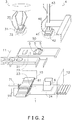
- FIG. 2 shows the internal configuration of the boxing apparatus 1.
- Articles 5 are inserted through the entry area 11.
- the articles 5 are conveyed a predetermined distance by a first conveyor 21, and are then raised up by the parallel link robot 3.
- Tubular vacuum-retaining tools 32 are provided to a head 31 of the parallel link robot 3, and the head 31 can hold an article 5 due to air being suctioned through the vacuum-retaining tools 32.
- the parallel link robot 3 moves and rotates an article 5 and places the article on a second conveyor 22, creating an article group 50 composed of a predetermined number of articles 5.
- the article group 50 is conveyed by the second conveyor 22 into proximity of the boxing robot 4, and stands by in that location.
- An empty packing box 6 is loaded into the boxing apparatus 1 from either a first packing box entry area 15 or a second packing box entry area 16.
- the packing box 6 then moves over conveyor rollers 81 to be pushed toward a third conveyor 23 by a box-moving mechanism 71.
- the third conveyor 23 is disposed beneath the first conveyor 21.
- the end part of the third conveyor 23 that is downstream in the conveying direction extends further downstream than the end part of the first conveyor that is downstream in the conveying direction.
- the packing box 6 is conveyed by the third conveyor 23 to a packing box waiting section 24 positioned beneath the boxing robot 4, and stand by in that location.
- Tubular vacuum-retaining tools 42 are provided to a head 41 of the boxing robot 4 as well, and the head 41 can hold an article group 50 at a time due to air being suctioned in through the vacuum-retaining tools 42.
- the boxing robot 4 raises an article group 50 up from the second conveyor 22, moves the article group horizontally, and carries the article group to above an empty packing box 6 that is standing by in the standing-by packing box section 24.
- the boxing robot 4 lowers the article group 50 to put it in the packing box 6.
- the boxing robot 4 repeats this operation to stack a predetermined number of article groups 50 inside the packing box 6.
- the packing box 6, which has finished being filled with a predetermined number of articles 5, is conveyed by the third conveyor 23 and ejected from the exit area 12.
- FIG. 3 is a plan view of the boxing apparatus 1. This view shows how articles 5 and/or article groups 50 are conveyed by the parallel link robot 3 and/or the boxing robot 4.
- the vacuum-retaining tools 32 of the parallel link robot 3 communicate with a hose 35 connected to the head 31, and the vacuum-retaining tools 42 of the boxing robot 4 communicate with a hose 46 connected to the head 41.
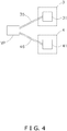
- the hose 35 and the hose 46 communicate with a vacuum pump VP.
- the vacuum pump VP generates suction force for holding the articles 5 and/or the article groups 50.
- the mass measurement device is constituted of the head 41 of the boxing robot 4, the hose 46, the vacuum pump VP, a detection unit DT ( FIG. 8 ) and computation unit COM ( FIG. 8 ) described hereinafter, and other components.
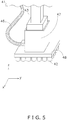
- FIG. 5 shows an external view of the head 41.
- the head 41 is attached to a mast 43 of the boxing robot 4.
- the head 41 has a cover 47 that covers an internal mechanism.
- the internal dimensions of the cover 47 are greater than the external dimensions of a base part 401 and movable part 402 described hereinafter, so as not to hinder changes in the relative positioning of the base part and movable part.
- the cover 47 may not be provided.
- FIG. 6 shows the head 41 with the cover 47 removed.
- the head 41 has the base part 401, an article-holding part 405, a force sensor FS, and an acceleration sensor AS.
- the base part 401 is composed of a rigid member made of, e.g., a metal or the like, and is fixed to the distal end of the mast 43 of the boxing robot 4, as shown in FIG. 6 .
- the base part 401 has a base-extending part 403.
- the article-holding part 405 includes the vacuum-retaining tools 42, a vacuum-retaining tool support part 48, and the movable part 402.
- the vacuum-retaining tools 42 are elastic, tubular members. Internal spaces in the vacuum-retaining tools 42 are used as air flow channels. The vacuum-retaining tools 42 deform and adhere firmly to the articles 5 when pressed thereon.
- the vacuum-retaining tool support part 48 is a hollow member to which a plurality of vacuum-retaining tools 42 are fixed. An internal space in the vacuum-retaining tool support part 48 communicates with the internal space of each of the vacuum-retaining tools 42.
- the movable part 402 is composed of a rigid member made of, e.g., a metal or the like, and is fixed to the vacuum-retaining tool support part 48 and the hose 46.
- the movable part 402 has an unillustrated air passage via which the internal space in the vacuum-retaining tool support part 48 and the hose 46 communicate. Furthermore, the movable part 402 has a movable extending part 404.
- FIG. 7 is an enlarged view of the force sensor FS and the surrounding structure.
- the force sensor FS is an element that can measure force exerted in a sensitivity direction S.
- the force sensor FS is constituted of a strain gauge-type load cell. Therefore, a physical characteristics such as a resistance value of the force sensor FS changes in accordance with the extent of the strain on the force sensor FS in the sensitivity direction S. This physical characteristic is used as a sensing signal.
- the force sensor FS has a fixed end EFX and a free end EFR.
- the fixed end EFX is fixed to the base-extending part 403.
- the free end EFR is fixed to the movable extending part 404.
- the x-axis direction with which the sensitivity direction S of the force sensor FS coincides is the x-axis direction with which the sensitivity direction S of the force sensor FS coincides.
- the x-axis direction coinciding with the sensitivity direction S is a horizontal direction
- the z-axis direction is a vertical direction.
- the acceleration sensor AS is installed on the movable part 402, and outputs acceleration signals corresponding to the acceleration of the movable part 402 in the x-axis direction, i.e. in the sensitivity direction S of the force sensor FS.
- the acceleration sensor AS can be constituted of a strain gauge-type load cell provided with a weight at its free end, a MEMS-type small acceleration sensor, an ordinary commercial acceleration sensor, or the like.
- the movable extending part 404 moves in the x-axis direction relative to the base-extending part 403. Strain in the sensitivity direction S coinciding with the x-axis direction thereby occurs in the force sensor FS.
- the force sensor FS outputs a sensing signal corresponding to the extent of the strain.
- the extent of the strain on the force sensor FS corresponds to force F ( FIG. 7 ) thought to be applied to the movable extending part 404.
- This force F increases and decreases in accordance with the mass of the held article group 50 and the acceleration of the head 41 in the x-axis direction. Therefore, the sensing signal outputted by the force sensor FS depends on the extent of the force F.
- FIG. 8 is a block diagram of a signal processing circuit of the mass measurement device according to the first embodiment of the present invention.
- the sensing signal outputted by the force sensor FS and the acceleration signal outputted by the acceleration sensor AS are detected by the detection unit DT and sent to the computation unit COM. From the sensing signal or from the sensing signal and the acceleration signal, the computation unit COM computes the mass of the article group 50 held by the head 41 and outputs this mass.
- the hose 46 travels in the y-z plane, and is disposed so as to not change position in the x-axis direction by any appreciable degree.
- the y-z plane is orthogonal to the sensitivity direction S of the force sensor FS.
- the flexible hose 46 While air-suctioning action is being performed by the operation of the vacuum pump VP, the flexible hose 46 might pulsate. At the instant when the air-suctioning action begins or ends due to the vacuum pump VP being controlled, the hose 46 might move. There could be cases in which movements of the hose 46 such as these result in the hose 46 exerting force on the article-holding part 405.
- the x-axis directional component which of these three components is equivalent to the force in the sensitivity direction S, is considered the smallest. Therefore, the effect that the movement of the hose 46 caused by the air-suctioning action has on the measurement of the force sensor FS and/or the acceleration sensor AS is restrained.
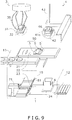
- FIG. 9 shows the internal configuration of a boxing apparatus 1 equipped with a mass measurement device according to a second embodiment of the present invention.
- the second embodiment has the same elements as the first embodiment aside from the structure of the head 41 a of the boxing robot 4 being different from the structure of the head 41 of the first embodiment.
- air suctioned through the vacuum-retaining tools 42 of the head 41 a of the boxing robot 4 first comes out of the head 41 a to pass through the hose 46, then returns to the head 41 a, and thereafter passes through the internal space in the mast 43 and heads toward the vacuum pump VP ( FIG. 3 ).
- the mass measurement device is also constituted of a head 41 a of the boxing robot 4, a hose 46, a vacuum pump VP, a detection unit DT, a computation unit COM, and other components.
- FIG. 10 shows an external view of the head 41 a.
- the head 41 a is attached to a mast 43 of the boxing robot 4.
- the head 41 a has a cover 47 that covers an internal mechanism.
- the internal dimensions of the cover 47 are greater than the external dimensions of a base part 401 and movable part 402 described hereinafter, so as not to hinder changes in the relative positioning of the base part and movable part.
- the cover 47 may not be provided.
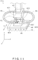
- FIG. 11 shows the head 41 a with the cover 47 removed.
- the head 41 a has the base part 401, an article-holding part 405, a force sensor FS, and an acceleration sensor AS.
- Two hoses 46 link the base part 401 and the movable part 402.
- the base part 401 is composed of a rigid member made of, e.g., a metal or the like, and is fixed to the distal end of the mast 43 of the boxing robot 4, as shown in FIG. 11 . Furthermore, the base part 401 has a base-extending part 403. The base part 401 of the head 41 a has an unillustrated air passage via which the internal space in the mast 43 and one end of each of the hoses 46 communicate.
- the article-holding part 405 includes vacuum-retaining tools 42, a vacuum-retaining tool support part 48, and the movable part 402.
- the vacuum-retaining tools 42 are elastic, tubular members. Internal spaces in the vacuum-retaining tools 42 are used as air flow channels. The vacuum-retaining tools 42 deform and adhere firmly to the articles 5 when pressed against the articles 5.
- the vacuum-retaining tool support part 48 is a hollow member to which multiple vacuum-retaining tools 42 are fixed. An internal space in the vacuum-retaining tool support part 48 communicates with each of the internal spaces of the vacuum-retaining tools 42.
- the movable part 402 is composed of a rigid member made of, e.g., a metal or the like, and is fixed to the vacuum-retaining tool support part 48 and the hoses 46.
- the movable part 402 has an unillustrated air passage via which the internal space in the vacuum-retaining tool support part 48 and the hoses 46 communicate. Furthermore, the movable part 402 has a movable extending part 404.
- the force sensor FS is installed according to the structure shown in FIG. 7 , similarly with respect to the first embodiment. Specifically, a fixed end EFX and a free end EFR of the force sensor FS are fixed to the base-extending part 403 and to the movable extending part 404, respectively.
- the sensitivity direction S of the force sensor FS is the x-axis direction, which is the horizontal direction.
- the acceleration sensor AS is installed on the movable part 402, similarly with respect to the first embodiment.
- the acceleration sensor AS outputs acceleration signals that correspond to the acceleration of the movable part 402 in the x-axis direction, i.e., in the sensitivity direction S of the force sensor FS.
- the operating principle of the mass measurement device according to the second embodiment is the same as in the first embodiment.
- the hoses 46 are disposed so as to travel through the y-z plane and not change by any appreciable degree in terms of x-axis directional position, as shown in FIG. 11 .
- the y-z plane is orthogonal to the sensitivity direction S of the force sensor FS.
- each hose 46 is supported at two points: on the base part 401 and on the movable part 402.
- FIG. 12 shows a head 41 b of a mass measurement device according to a first modification 2A of the second embodiment of the present invention.
- the x-axis, y-axis, and z-axis directions differ from those in FIG. 11 , and it should be noted that the x-axis direction is the vertical direction.
- the sensitivity direction S of the force sensor FS which coincides with the x-axis, is the vertical direction, unlike in the second embodiment ( FIG. 11 ).
- FIG. 13 is an enlarged view of the force sensor FS and the surrounding structure in the first modification 2A of the second embodiment.
- the movable extending part 404 moves in the x-axis direction relative to the base-extending part 403.
- the force sensor FS receives strain in the sensitivity direction S, which coincides with the x-axis direction, in accordance with vertical-direction force F, and outputs a sensing signal corresponding to the magnitude of this strain.
- the acceleration sensor AS also detects acceleration in the x-axis direction, which is the vertical direction.
- Two hoses 46 travel through the horizontal y-z plane, which is orthogonal to the sensitivity direction S, so as to not affect the force sensor FS or the acceleration sensor AS.
- the sensing signal outputted by the force sensor FS can be used to measure the mass of the articles while the head 41 has stopped. Furthermore, both the sensing signal outputted by the force sensor FS and the acceleration sensor outputted by the acceleration sensor AS can be used to measure the mass of the articles while the head 41 is moving in the x direction.
- FIG. 14 shows a head 41 c of a mass measurement device according to a second modification 2B of the second embodiment of the present invention.
- the x-axis, y-axis, and z-axis directions differ from those in FIG. 11 , and it should be noted that the x-axis direction is the vertical direction.
- the relative arrangement of the hoses 46 in relation to the force sensor FS differs from that of the head 41 b according to the first modification 2A of the second embodiment of the present invention. But, the operating principle is the same as that of the head 41 b.
- FIG. 15 shows a head 41 d of a mass measurement device according to a third embodiment of the present invention.
- the x-axis, y-axis, and z-axis directions are the same as those in FIG. 11 , and it should be noted that the z-axis direction is the vertical direction.
- the head 41 d of the third embodiment in place of a pair of hoses 46 of the head 41 a ( FIG. 11 ) according to the second embodiment, two sets each of which includes a base-part-side rigid pipe 461, a hose 462, and a movable-part-side rigid pipe 463 are employed.
- the head 41 d according to the third embodiment is otherwise the same as the head 41 a according to the second embodiment.
- the base-part-side rigid pipes 461 and the movable-part-side rigid pipes 463 are composed of a metal or another rigid material, and thus do not pulsate during suction action.
- the hose 462 links the base-part-side rigid pipe 461 and the movable-part-side rigid pipe 463.
- the sensitivity direction S of the sensor is the horizontal x-axis direction. Due to the presence of the flexible hoses 462, the movable part 402 can move relatively in the x-axis direction in relation to the base part 401. Therefore, the action of the force sensor FS is not disturbed.
- the sets of the base-part-side rigid pipes 461, the hoses 462, and the movable-part-side rigid pipes 463 are disposed in the y-z plane, which is orthogonal to the sensitivity direction S, the force sensor FS and the acceleration sensor AS are unlikely to be affected.
- FIG. 16 shows a head 41e of a mass measurement device according to a fourth embodiment of the present invention.
- the x-axis, y-axis, and z-axis directions are the same as those in FIG. 11 , and it should be noted that the z-axis direction is the vertical direction.
- the head 41e of the fourth embodiment in place of the pair of hoses 46 of the head 41 a ( FIG. 11 ) according to the second embodiment, two sets each of which includes a base-part-side rigid pipe 464 and a movable-part-side rigid pipe 465 are employed.
- the head 41 e according to the fourth embodiment is otherwise the same as the head 41 a according to the second embodiment.
- the sensitivity direction S of the sensor is the horizontal x-axis direction. Due to the presence of the gaps G, the movable part 402 can move relatively in the x-axis direction in relation to the base part 401. Therefore, the action of the force sensor FS is not disturbed.
- the sets of the base-part-side rigid pipes 464 and the movable-part-side rigid pipes 465 are disposed in the y-z plane, which is orthogonal to the sensitivity direction S, the force sensor FS and the acceleration sensor AS are unlikely to be affected.
- FIG. 17 shows a head 41f according to a fifth embodiment of the present invention.
- the x-axis, y-axis, and z-axis directions are the same as those in FIG. 11 , and it should be noted that the z-axis direction is the vertical direction.
- the head 41f of the fifth embodiment in place of the pair of hoses 46 of the head 41 a ( FIG. 11 ) according to the second embodiment, two sets each of which includes a base-part-side rigid pipe 466 and a movable-part-side rigid pipe 467 are employed.
- the head 41 f according to the fifth embodiment is otherwise the same as the head 41 a according to the second embodiment.
- the base-part-side rigid pipes 466 are inserted into the movable-part-side rigid pipes 467 so as to not deteriorate suction performance.
- the sensitivity direction S of the sensor is the horizontal x-axis direction. Because the inside diameter of the movable-part-side rigid pipes 467 is greater than the outside diameter of the base-part-side rigid pipes 466, the movable part 402 can move relatively in the x-axis direction in relation to the base part 401. Therefore, the action of the force sensor FS is not disturbed.
- the sets of the base-part-side rigid pipes 466 and the movable-part-side rigid pipes 467 are disposed in the y-z plane, which is orthogonal to the sensitivity direction S, the force sensor FS and the acceleration sensor AS are unlikely to be affected.
- the force sensor FS of the mass measurement device according to the present invention is not limited to a strain gauge-type load cell, and may be constituted of other elements and/or devices that can detect force.
- the force sensor FS may be an electrostatic capacitance-type load cell, a magnetostrictive load cell, or a force balance-type scale.
- the location where the mass measurement device according to the present invention is installed is not limited to the boxing robot 4, and may be the parallel link robot 3.
- mass measurement devices according to the present invention may be installed in both the parallel link robot 3 and the boxing robot 4. In this case, more accurate measurements could be taken by double-checking the mass of the articles. Furthermore, it is also possible to determine abnormalities in the actions of the mass measurement devices.
- Patent Literature 1 Japanese Laid-open Patent Publication No. 2013-79931
Landscapes
- Engineering & Computer Science (AREA)
- Physics & Mathematics (AREA)
- General Physics & Mathematics (AREA)
- Mechanical Engineering (AREA)
- Robotics (AREA)
- Manipulator (AREA)
Abstract
Description
- The present invention relates to a mass measurement device.
- Various devices have been envisioned which measure the mass of an article by using an article-holding part that vacuum-retains the article by suctioning air. A mass measurement device disclosed in Patent Literature 1 (Japanese Laid-open Patent Publication No.
2013-79931 - To suction air, for example, a vacuum pump and a suction channel via which the vacuum pump and an article-holding part communicate are presumably needed. However, when the suction channel is constituted of a flexible hose, it is likely that the suction channel pulsates during the air-suctioning action, or move the instant that the air-suctioning action begins or ends. Such suction channel movement could have an adverse effect on the sensing action of a sensor that measures the mass of an article. When the suction channel is constituted of a rigid pipe, by contrast, the movement of a movable part provided to the mass measurement device to be used in the sensing action could be hindered.
- An object of the present invention is to reduce measurement error caused by an air-suctioning action in a mass measurement device.
- A mass measurement device according to a first aspect of the present invention comprises a force sensor, a suction channel, a base part, an article-holding part, and a computation unit. The force sensor has a fixed end and a free end, and is configured to output a sensing signal in accordance with a magnitude of a force in a sensitivity direction. The suction channel is configured to pass suctioned air therethrough. The fixed end is fixed to the base part. The article-holding part is fixed to the free end, one end of the suction channel is connected to the article-holding part, and the article-holding part holds an article due to the suctioned air. The computation unit is configured to compute a mass of the article based on the sensing signal. The force sensor and the suction channel are disposed such that, among an x-axis directional component, a y-axis directional component, and a z-axis directional component of a force exerted on the article-holding part by the suction channel, the x-axis directional component is the smallest. The sensitivity direction is an x-axis direction, a direction orthogonal to the x-axis direction is a y-axis direction, and a direction orthogonal to both the x-axis direction and the y-axis direction is a z-axis direction.
- According to the aspect described above, because the x-axis directional component of the force exerted on the article-holding part by the suction channel is smaller than both the y-axis directional component and the z-axis directional component thereof, the component in the sensitivity direction of the force is reduced. As a result, measurement error caused by the air-suctioning action is reduced.
- A mass measurement device according to a second aspect of the present invention is the mass measurement device according to the first aspect, wherein the suction channel is disposed so as to pass through the base part.
- According to the aspect described above, the suction channel is supported at two points: at the article-holding part and at the base part. As a result, movement of the suction channel during air suction is further restrained.
- A mass measurement device according to a third aspect of the present invention is the mass measurement device according to the first or second aspect, wherein the suction channel has a hose disposed in a y-z plane which extends in the y-axis direction and the z-axis direction.
- According to the aspect described above, the hose of the suction channel does not extend in the x-axis direction. As a result, movement of the suction channel in the x-axis direction during air suction is further restrained.
- A mass measurement device according to a fourth aspect of the present invention is the mass measurement device according to any one of the first through third aspects, wherein the suction channel has a rigid pipe disposed in a y-z plane which extends in the y-axis direction and the z-axis direction.
- According to the aspect described above, the suction channel has rigidity and does not extend in the x-axis direction. As a result, movement of the suction channel in the x-axis direction during air suction is further restrained.
- A mass measurement device according to a fifth aspect of the present invention is the mass measurement device according to any of the first through third aspects, wherein the suction channel has a pair of rigid pipes separated by a gap.
- According to the aspect described above, the pair of rigid pipes can move relative to each other due to the presence of the gap. As a result, movement of the movable part used in the sensing action is unlikely to be hindered.
- A mass measurement device according to a sixth aspect of the present invention is the mass measurement device according to any one of the first through third aspects, wherein the suction channel has a pair of rigid pipes having different diameter sizes, one pipe being inserted into the other pipe.
- According to the aspect described above, because there is a difference in the diameter sizes, the pair of rigid pipes can move by a predetermined distance relative to each other. As a result, the movement of the movable part used in the sensing action is unlikely to be hindered.
- A mass measurement device according to a seventh aspect of the present invention is the mass measurement device according to any one of the first through sixth aspects, wherein the force exerted on the article-holding part by the suction channel is generated by pulsation of the suction channel during air suction, or by movement of the suction channel caused by start or end of air suction.
- According to the aspect described above, it is possible to restrain measurement error from being induced by pulsation of the suction channel during air suction or by movement of the suction channel caused by the start or end of air suction.
- A mass measurement device according to an eighth aspect of the present invention is the mass measurement device according to any one of the first through seventh aspects, further comprising a robot configured to cause the base part to move.
- According to the aspect described above, the article, which is the object of the mass measurement, can be moved.
- A mass measurement device according to a ninth aspect of the present invention is the mass measurement device according to any one of the first through eighth aspects, further comprising an acceleration sensor configured to output an acceleration signal in accordance with a magnitude of an acceleration of the article-holding part in the sensitivity direction. The computation unit is configured to compute the mass of the article based on the sensing signal outputted by the force sensor when the base part moves in the sensitivity direction, and the acceleration signal outputted by the acceleration sensor when the base part moves in the sensitivity direction.
- According to the aspect described above, the acceleration signal can be used for the mass computation in addition to the sensing signal of the force sensor. As a result, the mass of the article can be measured while the article is moving.
- A mass measurement device according to a tenth aspect of the present invention is the mass measurement device according to any one of the first through ninth aspects, wherein the sensitivity direction is a horizontal direction.
- With this configuration, measurements can be taken by detecting a force in a horizontal direction. As a result, it is possible to measure the mass of an article moving horizontally, for example.
- A mass measurement device according to an eleventh aspect of the present invention is the mass measurement device according to any one of the first through ninth aspects, wherein the sensitivity direction is a vertical direction.
- According to the aspect described above, measurements can be taken by detecting a force in a vertical direction. As a result, the mass of an article moving vertically can be measured. Another possibility is that the mass of an article remaining stationary can be measured by detecting the gravitational force acting on the article.
- A mass measurement device according to a twelfth aspect of the present invention is the mass measurement device according to any one of the first through eleventh aspects, wherein the force sensor is a strain gauge-type load cell.
- According to the aspect described above, it is possible to configure a mass measurement device that has high accuracy and is not readily affected by temperature changes.
- A mass measurement device according to a thirteenth aspect of the present invention is the mass measurement device according to any one of the first through twelfth aspects, further comprising a vacuum pump in communication with the suction channel.
- According to the aspect described above, a suction force for an article can be produced by the vacuum pump.
- Provided that the mass measurement device according to the present invention is used, measurement error caused by the air-suctioning action is reduced.
-
-
FIG. 1 is a side view of a boxing apparatus equipped with a mass measurement device according to the first embodiment of the present invention; -
FIG. 2 shows the internal configuration of the boxing apparatus shown inFIG. 1 ; -
FIG. 3 is a plan view of the boxing apparatus shown inFIG. 1 ; -
FIG. 4 shows an air suction mechanism used in the boxing apparatus shown inFIG. 1 ; -
FIG. 5 is a perspective view showing the mass measurement device according to the first embodiment of the present invention; -
FIG. 6 is a perspective view showing the mass measurement device according to the first embodiment of the present invention; -
FIG. 7 is an enlarged view showing a force sensor installed in the mass measurement device according to the first embodiment of the present invention; -
FIG. 8 is a block diagram of a signal processing circuit of the mass measurement device according to the first embodiment of the present invention; -
FIG. 9 shows the internal configuration of a boxing apparatus equipped with a mass measurement device according to a second embodiment of the present invention; -
FIG. 10 is a perspective view showing the mass measurement device according to the second embodiment of the present invention; -
FIG. 11 is a perspective view showing the mass measurement device according to the second embodiment of the present invention; -
FIG. 12 is a perspective view showing a mass measurement device according to a first modification 2A of the second embodiment of the present invention; -
FIG. 13 is an enlarged view showing a force sensor installed in the mass measurement device according to the first modification 2A of the second embodiment of the present invention; -
FIG. 14 is a perspective view showing a mass measurement device according to a second modification 2B of the second embodiment of the present invention; -
FIG. 15 is a perspective view showing a mass measurement device according to a third embodiment of the present invention; -
FIG. 16 is a perspective view showing a mass measurement device according to a fourth embodiment of the present invention; and -
FIG. 17 is a perspective view showing a mass measurement device according to a fifth embodiment of the present invention. -
FIG. 1 shows an external view of aboxing apparatus 1 equipped with a mass measurement device according to a first embodiment of the present invention. Thisboxing apparatus 1 is used for filling apacking box 6 withmultiple articles 5. - A
frame 10 of theboxing apparatus 1 is provided with anentry area 11 for receivingarticles 5, and anexit area 12 for ejecting apacking box 6 that has finished being filled withmultiple articles 5. Furthermore, aparallel link robot 3 and aboxing robot 4 are installed to theframe 10. -
FIG. 2 shows the internal configuration of theboxing apparatus 1. -
Articles 5 are inserted through theentry area 11. Thearticles 5 are conveyed a predetermined distance by afirst conveyor 21, and are then raised up by theparallel link robot 3. Tubular vacuum-retainingtools 32 are provided to ahead 31 of theparallel link robot 3, and thehead 31 can hold anarticle 5 due to air being suctioned through the vacuum-retainingtools 32. Theparallel link robot 3 moves and rotates anarticle 5 and places the article on asecond conveyor 22, creating anarticle group 50 composed of a predetermined number ofarticles 5. Thearticle group 50 is conveyed by thesecond conveyor 22 into proximity of theboxing robot 4, and stands by in that location. - An
empty packing box 6 is loaded into theboxing apparatus 1 from either a first packingbox entry area 15 or a second packingbox entry area 16. Thepacking box 6 then moves overconveyor rollers 81 to be pushed toward athird conveyor 23 by a box-movingmechanism 71. Thethird conveyor 23 is disposed beneath thefirst conveyor 21. The end part of thethird conveyor 23 that is downstream in the conveying direction extends further downstream than the end part of the first conveyor that is downstream in the conveying direction. Thepacking box 6 is conveyed by thethird conveyor 23 to a packingbox waiting section 24 positioned beneath theboxing robot 4, and stand by in that location. - Tubular vacuum-retaining
tools 42 are provided to ahead 41 of theboxing robot 4 as well, and thehead 41 can hold anarticle group 50 at a time due to air being suctioned in through the vacuum-retainingtools 42. First, theboxing robot 4 raises anarticle group 50 up from thesecond conveyor 22, moves the article group horizontally, and carries the article group to above anempty packing box 6 that is standing by in the standing-bypacking box section 24. Next, theboxing robot 4 lowers thearticle group 50 to put it in thepacking box 6. Theboxing robot 4 repeats this operation to stack a predetermined number ofarticle groups 50 inside thepacking box 6. - Finally, the
packing box 6, which has finished being filled with a predetermined number ofarticles 5, is conveyed by thethird conveyor 23 and ejected from theexit area 12. -
FIG. 3 is a plan view of theboxing apparatus 1. This view shows howarticles 5 and/orarticle groups 50 are conveyed by theparallel link robot 3 and/or theboxing robot 4. - As shown in
FIG. 2 , the vacuum-retainingtools 32 of theparallel link robot 3 communicate with ahose 35 connected to thehead 31, and the vacuum-retainingtools 42 of theboxing robot 4 communicate with ahose 46 connected to thehead 41. - As shown in
FIG. 4 , thehose 35 and thehose 46 communicate with a vacuum pump VP. The vacuum pump VP generates suction force for holding thearticles 5 and/or the article groups 50. - The mass measurement device according to the first embodiment of the present invention is constituted of the
head 41 of theboxing robot 4, thehose 46, the vacuum pump VP, a detection unit DT (FIG. 8 ) and computation unit COM (FIG. 8 ) described hereinafter, and other components. -
FIG. 5 shows an external view of thehead 41. Thehead 41 is attached to amast 43 of theboxing robot 4. Thehead 41 has acover 47 that covers an internal mechanism. The internal dimensions of thecover 47 are greater than the external dimensions of abase part 401 andmovable part 402 described hereinafter, so as not to hinder changes in the relative positioning of the base part and movable part. Thecover 47 may not be provided. -
FIG. 6 shows thehead 41 with thecover 47 removed. Thehead 41 has thebase part 401, an article-holdingpart 405, a force sensor FS, and an acceleration sensor AS. - The
base part 401 is composed of a rigid member made of, e.g., a metal or the like, and is fixed to the distal end of themast 43 of theboxing robot 4, as shown inFIG. 6 . Thebase part 401 has a base-extendingpart 403. - The article-holding
part 405 includes the vacuum-retainingtools 42, a vacuum-retainingtool support part 48, and themovable part 402. - The vacuum-retaining
tools 42 are elastic, tubular members. Internal spaces in the vacuum-retainingtools 42 are used as air flow channels. The vacuum-retainingtools 42 deform and adhere firmly to thearticles 5 when pressed thereon. - The vacuum-retaining
tool support part 48 is a hollow member to which a plurality of vacuum-retainingtools 42 are fixed. An internal space in the vacuum-retainingtool support part 48 communicates with the internal space of each of the vacuum-retainingtools 42. - The
movable part 402 is composed of a rigid member made of, e.g., a metal or the like, and is fixed to the vacuum-retainingtool support part 48 and thehose 46. Themovable part 402 has an unillustrated air passage via which the internal space in the vacuum-retainingtool support part 48 and thehose 46 communicate. Furthermore, themovable part 402 has a movable extendingpart 404. -
FIG. 7 is an enlarged view of the force sensor FS and the surrounding structure. The force sensor FS is an element that can measure force exerted in a sensitivity direction S. In the present embodiment, the force sensor FS is constituted of a strain gauge-type load cell. Therefore, a physical characteristics such as a resistance value of the force sensor FS changes in accordance with the extent of the strain on the force sensor FS in the sensitivity direction S. This physical characteristic is used as a sensing signal. - As shown in
FIG. 7 , the force sensor FS has a fixed end EFX and a free end EFR. The fixed end EFX is fixed to the base-extendingpart 403. The free end EFR is fixed to the movable extendingpart 404. - Among a mutually orthogonal x-axis direction, y-axis direction, and z-axis direction, which are shown in
FIG. 7 , it is the x-axis direction with which the sensitivity direction S of the force sensor FS coincides. In the present embodiment, the x-axis direction coinciding with the sensitivity direction S is a horizontal direction, and the z-axis direction is a vertical direction. - Returning to
FIG. 6 , the acceleration sensor AS is installed on themovable part 402, and outputs acceleration signals corresponding to the acceleration of themovable part 402 in the x-axis direction, i.e. in the sensitivity direction S of the force sensor FS. The acceleration sensor AS can be constituted of a strain gauge-type load cell provided with a weight at its free end, a MEMS-type small acceleration sensor, an ordinary commercial acceleration sensor, or the like. - When the
head 41 shown inFIG. 6 moves in the x-axis direction while holding anarticle group 50, the movable extendingpart 404 moves in the x-axis direction relative to the base-extendingpart 403. Strain in the sensitivity direction S coinciding with the x-axis direction thereby occurs in the force sensor FS. The force sensor FS outputs a sensing signal corresponding to the extent of the strain. - The extent of the strain on the force sensor FS corresponds to force F (
FIG. 7 ) thought to be applied to the movable extendingpart 404. This force F increases and decreases in accordance with the mass of the heldarticle group 50 and the acceleration of thehead 41 in the x-axis direction. Therefore, the sensing signal outputted by the force sensor FS depends on the extent of the force F. -
FIG. 8 is a block diagram of a signal processing circuit of the mass measurement device according to the first embodiment of the present invention. The sensing signal outputted by the force sensor FS and the acceleration signal outputted by the acceleration sensor AS are detected by the detection unit DT and sent to the computation unit COM. From the sensing signal or from the sensing signal and the acceleration signal, the computation unit COM computes the mass of thearticle group 50 held by thehead 41 and outputs this mass. - As shown in
FIG. 6 , thehose 46 travels in the y-z plane, and is disposed so as to not change position in the x-axis direction by any appreciable degree. The y-z plane is orthogonal to the sensitivity direction S of the force sensor FS. - While air-suctioning action is being performed by the operation of the vacuum pump VP, the
flexible hose 46 might pulsate. At the instant when the air-suctioning action begins or ends due to the vacuum pump VP being controlled, thehose 46 might move. There could be cases in which movements of thehose 46 such as these result in thehose 46 exerting force on the article-holdingpart 405. - When this force is broken down into the x-axis direction, the y-axis direction, and the z-axis direction, because the hose is traveling through the y-z plane, the x-axis directional component, which of these three components is equivalent to the force in the sensitivity direction S, is considered the smallest. Therefore, the effect that the movement of the
hose 46 caused by the air-suctioning action has on the measurement of the force sensor FS and/or the acceleration sensor AS is restrained. -
FIG. 9 shows the internal configuration of aboxing apparatus 1 equipped with a mass measurement device according to a second embodiment of the present invention. The second embodiment has the same elements as the first embodiment aside from the structure of thehead 41 a of theboxing robot 4 being different from the structure of thehead 41 of the first embodiment. Specifically, in the second embodiment, air suctioned through the vacuum-retainingtools 42 of thehead 41 a of theboxing robot 4 first comes out of thehead 41 a to pass through thehose 46, then returns to thehead 41 a, and thereafter passes through the internal space in themast 43 and heads toward the vacuum pump VP (FIG. 3 ). - The mass measurement device according to the second embodiment of the present invention is also constituted of a
head 41 a of theboxing robot 4, ahose 46, a vacuum pump VP, a detection unit DT, a computation unit COM, and other components. -
FIG. 10 shows an external view of thehead 41 a. Thehead 41 a is attached to amast 43 of theboxing robot 4. Thehead 41 a has acover 47 that covers an internal mechanism. The internal dimensions of thecover 47 are greater than the external dimensions of abase part 401 andmovable part 402 described hereinafter, so as not to hinder changes in the relative positioning of the base part and movable part. Thecover 47 may not be provided. -
FIG. 11 shows thehead 41 a with thecover 47 removed. Thehead 41 a has thebase part 401, an article-holdingpart 405, a force sensor FS, and an acceleration sensor AS. Twohoses 46 link thebase part 401 and themovable part 402. - The
base part 401 is composed of a rigid member made of, e.g., a metal or the like, and is fixed to the distal end of themast 43 of theboxing robot 4, as shown inFIG. 11 . Furthermore, thebase part 401 has a base-extendingpart 403. Thebase part 401 of thehead 41 a has an unillustrated air passage via which the internal space in themast 43 and one end of each of thehoses 46 communicate. - The article-holding
part 405 includes vacuum-retainingtools 42, a vacuum-retainingtool support part 48, and themovable part 402. - The vacuum-retaining
tools 42 are elastic, tubular members. Internal spaces in the vacuum-retainingtools 42 are used as air flow channels. The vacuum-retainingtools 42 deform and adhere firmly to thearticles 5 when pressed against thearticles 5. - The vacuum-retaining
tool support part 48 is a hollow member to which multiple vacuum-retainingtools 42 are fixed. An internal space in the vacuum-retainingtool support part 48 communicates with each of the internal spaces of the vacuum-retainingtools 42. - The
movable part 402 is composed of a rigid member made of, e.g., a metal or the like, and is fixed to the vacuum-retainingtool support part 48 and thehoses 46. Themovable part 402 has an unillustrated air passage via which the internal space in the vacuum-retainingtool support part 48 and thehoses 46 communicate. Furthermore, themovable part 402 has a movable extendingpart 404. - The force sensor FS is installed according to the structure shown in
FIG. 7 , similarly with respect to the first embodiment. Specifically, a fixed end EFX and a free end EFR of the force sensor FS are fixed to the base-extendingpart 403 and to the movable extendingpart 404, respectively. The sensitivity direction S of the force sensor FS is the x-axis direction, which is the horizontal direction. - Returning to
FIG. 11 , the acceleration sensor AS is installed on themovable part 402, similarly with respect to the first embodiment. The acceleration sensor AS outputs acceleration signals that correspond to the acceleration of themovable part 402 in the x-axis direction, i.e., in the sensitivity direction S of the force sensor FS. - The operating principle of the mass measurement device according to the second embodiment is the same as in the first embodiment.
- Similarly, with respect to the first embodiment, the
hoses 46 are disposed so as to travel through the y-z plane and not change by any appreciable degree in terms of x-axis directional position, as shown inFIG. 11 . The y-z plane is orthogonal to the sensitivity direction S of the force sensor FS. - Additionally, in the second embodiment, each
hose 46 is supported at two points: on thebase part 401 and on themovable part 402. - Therefore, the effect that the movement of the
hoses 46 caused by the air-suctioning action has on the measurement of the force sensor FS and/or the acceleration sensor AS is further restrained. -
FIG. 12 shows ahead 41 b of a mass measurement device according to a first modification 2A of the second embodiment of the present invention. In this drawing, the x-axis, y-axis, and z-axis directions differ from those inFIG. 11 , and it should be noted that the x-axis direction is the vertical direction. With the mass measurement device according to the first modification 2A of the second embodiment, the sensitivity direction S of the force sensor FS, which coincides with the x-axis, is the vertical direction, unlike in the second embodiment (FIG. 11 ). -
FIG. 13 is an enlarged view of the force sensor FS and the surrounding structure in the first modification 2A of the second embodiment. The movable extendingpart 404 moves in the x-axis direction relative to the base-extendingpart 403. At this time, the force sensor FS receives strain in the sensitivity direction S, which coincides with the x-axis direction, in accordance with vertical-direction force F, and outputs a sensing signal corresponding to the magnitude of this strain. - Returning to
FIG. 12 , the acceleration sensor AS also detects acceleration in the x-axis direction, which is the vertical direction. - Two
hoses 46 travel through the horizontal y-z plane, which is orthogonal to the sensitivity direction S, so as to not affect the force sensor FS or the acceleration sensor AS. - With this configuration, because the sensitivity direction S is the vertical direction, the sensing signal outputted by the force sensor FS can be used to measure the mass of the articles while the
head 41 has stopped. Furthermore, both the sensing signal outputted by the force sensor FS and the acceleration sensor outputted by the acceleration sensor AS can be used to measure the mass of the articles while thehead 41 is moving in the x direction. -
FIG. 14 shows ahead 41 c of a mass measurement device according to a second modification 2B of the second embodiment of the present invention. InFIG. 14 , the x-axis, y-axis, and z-axis directions differ from those inFIG. 11 , and it should be noted that the x-axis direction is the vertical direction. With thehead 41 c of the mass measurement device according to the second modification 2B of the second embodiment of the present invention, the relative arrangement of thehoses 46 in relation to the force sensor FS differs from that of thehead 41 b according to the first modification 2A of the second embodiment of the present invention. But, the operating principle is the same as that of thehead 41 b. -
FIG. 15 shows ahead 41 d of a mass measurement device according to a third embodiment of the present invention. In this drawing, the x-axis, y-axis, and z-axis directions are the same as those inFIG. 11 , and it should be noted that the z-axis direction is the vertical direction. In thehead 41 d of the third embodiment, in place of a pair ofhoses 46 of thehead 41 a (FIG. 11 ) according to the second embodiment, two sets each of which includes a base-part-siderigid pipe 461, ahose 462, and a movable-part-siderigid pipe 463 are employed. Thehead 41 d according to the third embodiment is otherwise the same as thehead 41 a according to the second embodiment. - The base-part-side
rigid pipes 461 and the movable-part-siderigid pipes 463 are composed of a metal or another rigid material, and thus do not pulsate during suction action. Thehose 462 links the base-part-siderigid pipe 461 and the movable-part-siderigid pipe 463. - The sensitivity direction S of the sensor is the horizontal x-axis direction. Due to the presence of the
flexible hoses 462, themovable part 402 can move relatively in the x-axis direction in relation to thebase part 401. Therefore, the action of the force sensor FS is not disturbed. - Because the sets of the base-part-side
rigid pipes 461, thehoses 462, and the movable-part-siderigid pipes 463 are disposed in the y-z plane, which is orthogonal to the sensitivity direction S, the force sensor FS and the acceleration sensor AS are unlikely to be affected. -
FIG. 16 shows ahead 41e of a mass measurement device according to a fourth embodiment of the present invention. In this drawing, the x-axis, y-axis, and z-axis directions are the same as those inFIG. 11 , and it should be noted that the z-axis direction is the vertical direction. In thehead 41e of the fourth embodiment, in place of the pair ofhoses 46 of thehead 41 a (FIG. 11 ) according to the second embodiment, two sets each of which includes a base-part-siderigid pipe 464 and a movable-part-siderigid pipe 465 are employed. Thehead 41 e according to the fourth embodiment is otherwise the same as thehead 41 a according to the second embodiment. - Between the base-part-side
rigid pipe 461 and the movable-part-siderigid pipe 465 there is provided a gap G with an extent enough to deteriorate the suction performance. - The sensitivity direction S of the sensor is the horizontal x-axis direction. Due to the presence of the gaps G, the
movable part 402 can move relatively in the x-axis direction in relation to thebase part 401. Therefore, the action of the force sensor FS is not disturbed. - Because the sets of the base-part-side
rigid pipes 464 and the movable-part-siderigid pipes 465 are disposed in the y-z plane, which is orthogonal to the sensitivity direction S, the force sensor FS and the acceleration sensor AS are unlikely to be affected. -
FIG. 17 shows ahead 41f according to a fifth embodiment of the present invention. In this drawing, the x-axis, y-axis, and z-axis directions are the same as those inFIG. 11 , and it should be noted that the z-axis direction is the vertical direction. In thehead 41f of the fifth embodiment, in place of the pair ofhoses 46 of thehead 41 a (FIG. 11 ) according to the second embodiment, two sets each of which includes a base-part-siderigid pipe 466 and a movable-part-siderigid pipe 467 are employed. Thehead 41 f according to the fifth embodiment is otherwise the same as thehead 41 a according to the second embodiment. - The base-part-side
rigid pipes 466 are inserted into the movable-part-siderigid pipes 467 so as to not deteriorate suction performance. - The sensitivity direction S of the sensor is the horizontal x-axis direction. Because the inside diameter of the movable-part-side
rigid pipes 467 is greater than the outside diameter of the base-part-siderigid pipes 466, themovable part 402 can move relatively in the x-axis direction in relation to thebase part 401. Therefore, the action of the force sensor FS is not disturbed. - Because the sets of the base-part-side
rigid pipes 466 and the movable-part-siderigid pipes 467 are disposed in the y-z plane, which is orthogonal to the sensitivity direction S, the force sensor FS and the acceleration sensor AS are unlikely to be affected. - The force sensor FS of the mass measurement device according to the present invention is not limited to a strain gauge-type load cell, and may be constituted of other elements and/or devices that can detect force. For example, the force sensor FS may be an electrostatic capacitance-type load cell, a magnetostrictive load cell, or a force balance-type scale.
- The location where the mass measurement device according to the present invention is installed is not limited to the
boxing robot 4, and may be theparallel link robot 3. - Alternatively, mass measurement devices according to the present invention may be installed in both the
parallel link robot 3 and theboxing robot 4. In this case, more accurate measurements could be taken by double-checking the mass of the articles. Furthermore, it is also possible to determine abnormalities in the actions of the mass measurement devices. -
- 1
- Boxing apparatus
- 3
- Parallel link robot
- 4
- Boxing robot
- 5
- Article
- 6
- Packing box
- 10
- Frame
- 11
- Entry area
- 12
- Exit area
- 15
- First packing box entry area
- 16
- Second packing box entry area
- 21
- First conveyor
- 22
- Second conveyor
- 23
- Third conveyor
- 24
- Packing box waiting section
- 31
- Head
- 32
- Vacuum-retaining tool
- 35
- Hose
- 41, 41a, 41b, 41c, 41d, 41e, 41f
- Head
- 42
- Vacuum-retaining tool
- 43
- Mast
- 46
- Hose
- 47
- Cover
- 48
- Vacuum-retaining tool support part
- 50
- Article group
- 71
- Box-moving mechanism
- 81
- Conveyor roller
- 401
- Base part
- 402
- Movable part
- 403
- Base-extending part
- 404
- Movable extending part
- 405
- Article-holding part
- 461
- Base-part-side rigid pipe
- 462
- Hose
- 463
- Movable-part-side rigid pipe
- 464
- Base-part-side rigid pipe
- 465
- Movable-part-side rigid pipe
- 466
- Base-part-side rigid pipe
- 467
- Movable-part-side rigid pipe
- FS
- Force sensor
- EFX
- Fixed end
- EFR
- Free end
- AS
- Acceleration sensor
- G
- Gap
- [Patent Literature 1] Japanese Laid-open Patent Publication No.
2013-79931
Claims (13)
- A mass measurement device comprising:a force sensor having a fixed end and a free end, and configured to output a sensing signal in accordance with a magnitude of a force in a sensitivity direction;a suction channel configured to pass suctioned air therethrough;a base part to which said fixed end is fixed;an article-holding part fixed to said free end, one end of said suction channel being connected to said article-holding part, and configured to hold an article due to said suctioned air; anda computation unit configured to compute a mass of said article based on said sensing signal;
whereinsaid force sensor and said suction channel are disposed such that, among an x-axis directional component, a y-axis directional component, and a z-axis directional component of a force exerted on said article-holding part by said suction channel, said x-axis directional component is the smallest, where said sensitivity direction is an x-axis direction, a direction orthogonal to said x-axis direction is a y-axis direction, and a direction orthogonal to both said x-axis direction and said y-axis direction is a z-axis direction. - The mass measurement device according to claim 1, wherein
said suction channel is disposed so as to pass through said base part. - The mass measurement device according to claim 1 or 2, wherein
said suction channel has a hose disposed in a y-z plane, which extends in said y-axis direction and said z-axis direction. - The mass measurement device according to any one of claims 1 to 3, wherein
said suction channel has a rigid pipe disposed in a y-z plane, which extends in said y-axis direction and said z-axis direction. - The mass measurement device according to any one of claims 1 to 3, wherein said suction channel has a pair of rigid pipes separated by a gap.
- The mass measurement device according to any one of claims 1 to 3, wherein
said suction channel has a pair of rigid pipes having different diameters, one pipe being inserted into the other pipe. - The mass measurement device according to any one of claims 1 to 6, wherein
said force exerted on said article-holding part by said suction channel is generated by pulsation of said suction channel during air suction, or by movement of said suction channel caused by start or end of air suction. - The mass measurement device according to any one of claims 1 to 7, further comprising:a robot configured to cause said base part to move.
- The mass measurement device according to any one of claims 1 to 8 further comprising:an acceleration sensor configured to output an acceleration signal in accordance with a magnitude of an acceleration of said article-holding part in said sensitivity direction;
whereinsaid computation unit is configured to compute said mass of said article based on:said sensing signal outputted by said force sensor when said base part moves in said sensitivity direction; andsaid acceleration signal outputted by said acceleration sensor when said base part moves in said sensitivity direction. - The mass measurement device according to any one of claims 1 to 9, wherein said sensitivity direction is a horizontal direction.
- The mass measurement device according to any one of claims 1 to 9, wherein said sensitivity direction is a vertical direction.
- The mass measurement device according to any one of claims 1 to 11, wherein said force sensor is a strain gauge-type load cell.
- The mass measurement device according to any one of claims 1 to 12, further comprising:a vacuum pump in communication with said suction channel.
Applications Claiming Priority (2)
| Application Number | Priority Date | Filing Date | Title |
|---|---|---|---|
| JP2014191638A JP6426415B2 (en) | 2014-09-19 | 2014-09-19 | Mass measuring device |
| PCT/JP2015/076378 WO2016043250A1 (en) | 2014-09-19 | 2015-09-17 | Mass measurement device |
Publications (3)
| Publication Number | Publication Date |
|---|---|
| EP3196608A1 true EP3196608A1 (en) | 2017-07-26 |
| EP3196608A4 EP3196608A4 (en) | 2018-05-09 |
| EP3196608B1 EP3196608B1 (en) | 2022-03-30 |
Family
ID=55533286
Family Applications (1)
| Application Number | Title | Priority Date | Filing Date |
|---|---|---|---|
| EP15841664.4A Not-in-force EP3196608B1 (en) | 2014-09-19 | 2015-09-17 | Mass measurement device |
Country Status (5)
| Country | Link |
|---|---|
| US (1) | US10352756B2 (en) |
| EP (1) | EP3196608B1 (en) |
| JP (1) | JP6426415B2 (en) |
| CN (1) | CN106716082B (en) |
| WO (1) | WO2016043250A1 (en) |
Cited By (1)
| Publication number | Priority date | Publication date | Assignee | Title |
|---|---|---|---|---|
| EP3782941A1 (en) * | 2019-08-20 | 2021-02-24 | J. Schmalz GmbH | Lifting device and method for operating a lifting device |
Families Citing this family (2)
| Publication number | Priority date | Publication date | Assignee | Title |
|---|---|---|---|---|
| JP7047522B2 (en) * | 2018-03-26 | 2022-04-05 | 三菱電機株式会社 | Gripping device |
| CN117740222B (en) * | 2024-02-21 | 2024-04-26 | 贵州大学 | A kind of imitation wood beam prestressing test device |
Family Cites Families (11)
| Publication number | Priority date | Publication date | Assignee | Title |
|---|---|---|---|---|
| JPH0894424A (en) * | 1994-09-26 | 1996-04-12 | Tohoku Munekata Kk | Weight measuring device |
| JPH09262786A (en) * | 1996-03-27 | 1997-10-07 | Kobe Steel Ltd | Depalletizing hand device |
| WO2006126218A1 (en) * | 2005-05-26 | 2006-11-30 | Lpe S.P.A. | Vacuum system for wafer handling |
| US7514639B2 (en) * | 2006-09-21 | 2009-04-07 | Technical Weighing Services, Inc. | Apparatus, system and method for weighing loads in motion |
| JP4659897B2 (en) * | 2009-08-07 | 2011-03-30 | 有限会社高橋製作所 | Pressure gauge |
| JP5129371B1 (en) * | 2011-07-27 | 2013-01-30 | ファナック株式会社 | Suction robot hand with weight measurement function |
| EP2759815B1 (en) * | 2011-09-20 | 2018-02-28 | Ishida Co., Ltd. | Mass measurement device |
| JP2013079931A (en) | 2011-09-20 | 2013-05-02 | Ishida Co Ltd | Mass measurement device |
| JP2013171948A (en) * | 2012-02-20 | 2013-09-02 | Sumitomo Electric Ind Ltd | Light-emitting element, epitaxial wafer and manufacturing method of the same |
| JP6004671B2 (en) * | 2012-03-05 | 2016-10-12 | 株式会社ジェイ・エム・エス | Weight measuring device |
| EP3112277B1 (en) * | 2014-02-28 | 2021-10-27 | Ishida Co., Ltd. | Boxing system |
-
2014
- 2014-09-19 JP JP2014191638A patent/JP6426415B2/en not_active Expired - Fee Related
-
2015
- 2015-09-17 WO PCT/JP2015/076378 patent/WO2016043250A1/en not_active Ceased
- 2015-09-17 CN CN201580049113.3A patent/CN106716082B/en not_active Expired - Fee Related
- 2015-09-17 US US15/511,008 patent/US10352756B2/en active Active
- 2015-09-17 EP EP15841664.4A patent/EP3196608B1/en not_active Not-in-force
Cited By (1)
| Publication number | Priority date | Publication date | Assignee | Title |
|---|---|---|---|---|
| EP3782941A1 (en) * | 2019-08-20 | 2021-02-24 | J. Schmalz GmbH | Lifting device and method for operating a lifting device |
Also Published As
| Publication number | Publication date |
|---|---|
| JP2016061732A (en) | 2016-04-25 |
| CN106716082B (en) | 2019-10-18 |
| CN106716082A (en) | 2017-05-24 |
| WO2016043250A1 (en) | 2016-03-24 |
| EP3196608B1 (en) | 2022-03-30 |
| US10352756B2 (en) | 2019-07-16 |
| JP6426415B2 (en) | 2018-11-21 |
| US20170284855A1 (en) | 2017-10-05 |
| EP3196608A4 (en) | 2018-05-09 |
Similar Documents
| Publication | Publication Date | Title |
|---|---|---|
| EP3196608B1 (en) | Mass measurement device | |
| CN101031803B (en) | Acceleration measuring device | |
| KR101464148B1 (en) | Compensation of measurement errors due to dynamic deformations in a coordinate measuring machine | |
| JP5383760B2 (en) | Robot with workpiece mass measurement function | |
| JP6095676B2 (en) | Wind tunnel balance | |
| EP2636991A1 (en) | Measuring machine with compensation system for errors due to the thermal deformation of a scale of a linear transducer | |
| CN104976982A (en) | Detection apparatus of T-shaped elevator guide rail | |
| JP2013079931A (en) | Mass measurement device | |
| CN105181452B (en) | A kind of dynamometry component | |
| CN104930994A (en) | Transposition wire jumper on-line detection device | |
| EP1186876A3 (en) | A bag testing machine | |
| JP6592696B2 (en) | Pipe measuring device and pipe measuring method | |
| KR101055314B1 (en) | Damage Detection Method of Structures Using Strain and Acceleration Signals | |
| KR101344891B1 (en) | Wind tunnel balance for measuring axial force of long axis type test model | |
| RU2010124610A (en) | GRAVIMETRIC DEVICE NOT DEPENDING ON ORIENTATION | |
| JP6105515B2 (en) | Force sensor testing device | |
| JP5550472B2 (en) | Weight sorter | |
| JP5524305B2 (en) | Parts counting device | |
| ITTO20070612A1 (en) | METHOD AND DEVICE TO DETERMINE THE MASS OF POSTAL ITEMS TRANSFERRED IN SUCCESSION ALONG A ROUTE | |
| JP5828751B2 (en) | Combination scale | |
| JP7047522B2 (en) | Gripping device | |
| KR20180045943A (en) | Aperture for enhancing the performance of dynamic weighing systems using loadcell channel separation | |
| KR20160103799A (en) | Air hose and sensor lines arrangement structure of injection molding goods take-out apparatus | |
| CN105698743A (en) | A pressure detection apparatus, a support mechanism and a conveying device | |
| JP7288001B2 (en) | Sample container spring inspection device |
Legal Events
| Date | Code | Title | Description |
|---|---|---|---|
| STAA | Information on the status of an ep patent application or granted ep patent |
Free format text: STATUS: THE INTERNATIONAL PUBLICATION HAS BEEN MADE |
|
| PUAI | Public reference made under article 153(3) epc to a published international application that has entered the european phase |
Free format text: ORIGINAL CODE: 0009012 |
|
| STAA | Information on the status of an ep patent application or granted ep patent |
Free format text: STATUS: REQUEST FOR EXAMINATION WAS MADE |
|
| 17P | Request for examination filed |
Effective date: 20170411 |
|
| AK | Designated contracting states |
Kind code of ref document: A1 Designated state(s): AL AT BE BG CH CY CZ DE DK EE ES FI FR GB GR HR HU IE IS IT LI LT LU LV MC MK MT NL NO PL PT RO RS SE SI SK SM TR |
|
| AX | Request for extension of the european patent |
Extension state: BA ME |
|
| DAV | Request for validation of the european patent (deleted) | ||
| DAX | Request for extension of the european patent (deleted) | ||
| A4 | Supplementary search report drawn up and despatched |
Effective date: 20180411 |
|
| RIC1 | Information provided on ipc code assigned before grant |
Ipc: G01G 3/14 20060101AFI20180403BHEP Ipc: B25J 9/00 20060101ALI20180403BHEP Ipc: G01G 23/00 20060101ALI20180403BHEP Ipc: B65B 61/28 20060101ALI20180403BHEP Ipc: G01L 1/22 20060101ALI20180403BHEP Ipc: B65G 47/90 20060101ALI20180403BHEP Ipc: G01G 23/01 20060101ALI20180403BHEP Ipc: G01G 19/18 20060101ALI20180403BHEP Ipc: B25J 15/06 20060101ALI20180403BHEP Ipc: B65G 47/91 20060101ALI20180403BHEP |
|
| STAA | Information on the status of an ep patent application or granted ep patent |
Free format text: STATUS: EXAMINATION IS IN PROGRESS |
|
| 17Q | First examination report despatched |
Effective date: 20210303 |
|
| GRAP | Despatch of communication of intention to grant a patent |
Free format text: ORIGINAL CODE: EPIDOSNIGR1 |
|
| STAA | Information on the status of an ep patent application or granted ep patent |
Free format text: STATUS: GRANT OF PATENT IS INTENDED |
|
| INTG | Intention to grant announced |
Effective date: 20210923 |
|
| GRAS | Grant fee paid |
Free format text: ORIGINAL CODE: EPIDOSNIGR3 |
|
| GRAA | (expected) grant |
Free format text: ORIGINAL CODE: 0009210 |
|
| STAA | Information on the status of an ep patent application or granted ep patent |
Free format text: STATUS: THE PATENT HAS BEEN GRANTED |
|
| AK | Designated contracting states |
Kind code of ref document: B1 Designated state(s): AL AT BE BG CH CY CZ DE DK EE ES FI FR GB GR HR HU IE IS IT LI LT LU LV MC MK MT NL NO PL PT RO RS SE SI SK SM TR |
|
| REG | Reference to a national code |
Ref country code: GB Ref legal event code: FG4D |
|
| REG | Reference to a national code |
Ref country code: CH Ref legal event code: EP |
|
| REG | Reference to a national code |
Ref country code: AT Ref legal event code: REF Ref document number: 1479612 Country of ref document: AT Kind code of ref document: T Effective date: 20220415 |
|
| REG | Reference to a national code |
Ref country code: DE Ref legal event code: R096 Ref document number: 602015077917 Country of ref document: DE |
|
| REG | Reference to a national code |
Ref country code: IE Ref legal event code: FG4D |
|
| REG | Reference to a national code |
Ref country code: LT Ref legal event code: MG9D |
|
| PG25 | Lapsed in a contracting state [announced via postgrant information from national office to epo] |
Ref country code: SE Free format text: LAPSE BECAUSE OF FAILURE TO SUBMIT A TRANSLATION OF THE DESCRIPTION OR TO PAY THE FEE WITHIN THE PRESCRIBED TIME-LIMIT Effective date: 20220330 Ref country code: RS Free format text: LAPSE BECAUSE OF FAILURE TO SUBMIT A TRANSLATION OF THE DESCRIPTION OR TO PAY THE FEE WITHIN THE PRESCRIBED TIME-LIMIT Effective date: 20220330 Ref country code: NO Free format text: LAPSE BECAUSE OF FAILURE TO SUBMIT A TRANSLATION OF THE DESCRIPTION OR TO PAY THE FEE WITHIN THE PRESCRIBED TIME-LIMIT Effective date: 20220630 Ref country code: LT Free format text: LAPSE BECAUSE OF FAILURE TO SUBMIT A TRANSLATION OF THE DESCRIPTION OR TO PAY THE FEE WITHIN THE PRESCRIBED TIME-LIMIT Effective date: 20220330 Ref country code: HR Free format text: LAPSE BECAUSE OF FAILURE TO SUBMIT A TRANSLATION OF THE DESCRIPTION OR TO PAY THE FEE WITHIN THE PRESCRIBED TIME-LIMIT Effective date: 20220330 Ref country code: BG Free format text: LAPSE BECAUSE OF FAILURE TO SUBMIT A TRANSLATION OF THE DESCRIPTION OR TO PAY THE FEE WITHIN THE PRESCRIBED TIME-LIMIT Effective date: 20220630 |
|
| REG | Reference to a national code |
Ref country code: NL Ref legal event code: MP Effective date: 20220330 |
|
| REG | Reference to a national code |
Ref country code: AT Ref legal event code: MK05 Ref document number: 1479612 Country of ref document: AT Kind code of ref document: T Effective date: 20220330 |
|
| PG25 | Lapsed in a contracting state [announced via postgrant information from national office to epo] |
Ref country code: LV Free format text: LAPSE BECAUSE OF FAILURE TO SUBMIT A TRANSLATION OF THE DESCRIPTION OR TO PAY THE FEE WITHIN THE PRESCRIBED TIME-LIMIT Effective date: 20220330 Ref country code: GR Free format text: LAPSE BECAUSE OF FAILURE TO SUBMIT A TRANSLATION OF THE DESCRIPTION OR TO PAY THE FEE WITHIN THE PRESCRIBED TIME-LIMIT Effective date: 20220701 Ref country code: FI Free format text: LAPSE BECAUSE OF FAILURE TO SUBMIT A TRANSLATION OF THE DESCRIPTION OR TO PAY THE FEE WITHIN THE PRESCRIBED TIME-LIMIT Effective date: 20220330 |
|
| PG25 | Lapsed in a contracting state [announced via postgrant information from national office to epo] |
Ref country code: NL Free format text: LAPSE BECAUSE OF FAILURE TO SUBMIT A TRANSLATION OF THE DESCRIPTION OR TO PAY THE FEE WITHIN THE PRESCRIBED TIME-LIMIT Effective date: 20220330 |
|
| PG25 | Lapsed in a contracting state [announced via postgrant information from national office to epo] |
Ref country code: SM Free format text: LAPSE BECAUSE OF FAILURE TO SUBMIT A TRANSLATION OF THE DESCRIPTION OR TO PAY THE FEE WITHIN THE PRESCRIBED TIME-LIMIT Effective date: 20220330 Ref country code: SK Free format text: LAPSE BECAUSE OF FAILURE TO SUBMIT A TRANSLATION OF THE DESCRIPTION OR TO PAY THE FEE WITHIN THE PRESCRIBED TIME-LIMIT Effective date: 20220330 Ref country code: RO Free format text: LAPSE BECAUSE OF FAILURE TO SUBMIT A TRANSLATION OF THE DESCRIPTION OR TO PAY THE FEE WITHIN THE PRESCRIBED TIME-LIMIT Effective date: 20220330 Ref country code: PT Free format text: LAPSE BECAUSE OF FAILURE TO SUBMIT A TRANSLATION OF THE DESCRIPTION OR TO PAY THE FEE WITHIN THE PRESCRIBED TIME-LIMIT Effective date: 20220801 Ref country code: ES Free format text: LAPSE BECAUSE OF FAILURE TO SUBMIT A TRANSLATION OF THE DESCRIPTION OR TO PAY THE FEE WITHIN THE PRESCRIBED TIME-LIMIT Effective date: 20220330 Ref country code: EE Free format text: LAPSE BECAUSE OF FAILURE TO SUBMIT A TRANSLATION OF THE DESCRIPTION OR TO PAY THE FEE WITHIN THE PRESCRIBED TIME-LIMIT Effective date: 20220330 Ref country code: CZ Free format text: LAPSE BECAUSE OF FAILURE TO SUBMIT A TRANSLATION OF THE DESCRIPTION OR TO PAY THE FEE WITHIN THE PRESCRIBED TIME-LIMIT Effective date: 20220330 Ref country code: AT Free format text: LAPSE BECAUSE OF FAILURE TO SUBMIT A TRANSLATION OF THE DESCRIPTION OR TO PAY THE FEE WITHIN THE PRESCRIBED TIME-LIMIT Effective date: 20220330 |
|
| PGFP | Annual fee paid to national office [announced via postgrant information from national office to epo] |
Ref country code: GB Payment date: 20220920 Year of fee payment: 8 Ref country code: DE Payment date: 20220620 Year of fee payment: 8 |
|
| PG25 | Lapsed in a contracting state [announced via postgrant information from national office to epo] |
Ref country code: PL Free format text: LAPSE BECAUSE OF FAILURE TO SUBMIT A TRANSLATION OF THE DESCRIPTION OR TO PAY THE FEE WITHIN THE PRESCRIBED TIME-LIMIT Effective date: 20220330 Ref country code: IS Free format text: LAPSE BECAUSE OF FAILURE TO SUBMIT A TRANSLATION OF THE DESCRIPTION OR TO PAY THE FEE WITHIN THE PRESCRIBED TIME-LIMIT Effective date: 20220730 Ref country code: AL Free format text: LAPSE BECAUSE OF FAILURE TO SUBMIT A TRANSLATION OF THE DESCRIPTION OR TO PAY THE FEE WITHIN THE PRESCRIBED TIME-LIMIT Effective date: 20220330 |
|
| REG | Reference to a national code |
Ref country code: DE Ref legal event code: R097 Ref document number: 602015077917 Country of ref document: DE |
|
| PG25 | Lapsed in a contracting state [announced via postgrant information from national office to epo] |
Ref country code: DK Free format text: LAPSE BECAUSE OF FAILURE TO SUBMIT A TRANSLATION OF THE DESCRIPTION OR TO PAY THE FEE WITHIN THE PRESCRIBED TIME-LIMIT Effective date: 20220330 |
|
| PLBE | No opposition filed within time limit |
Free format text: ORIGINAL CODE: 0009261 |
|
| STAA | Information on the status of an ep patent application or granted ep patent |
Free format text: STATUS: NO OPPOSITION FILED WITHIN TIME LIMIT |
|
| 26N | No opposition filed |
Effective date: 20230103 |
|
| PG25 | Lapsed in a contracting state [announced via postgrant information from national office to epo] |
Ref country code: MC Free format text: LAPSE BECAUSE OF FAILURE TO SUBMIT A TRANSLATION OF THE DESCRIPTION OR TO PAY THE FEE WITHIN THE PRESCRIBED TIME-LIMIT Effective date: 20220330 |
|
| REG | Reference to a national code |
Ref country code: CH Ref legal event code: PL |
|
| REG | Reference to a national code |
Ref country code: BE Ref legal event code: MM Effective date: 20220930 |
|
| PG25 | Lapsed in a contracting state [announced via postgrant information from national office to epo] |
Ref country code: SI Free format text: LAPSE BECAUSE OF FAILURE TO SUBMIT A TRANSLATION OF THE DESCRIPTION OR TO PAY THE FEE WITHIN THE PRESCRIBED TIME-LIMIT Effective date: 20220330 |
|
| PG25 | Lapsed in a contracting state [announced via postgrant information from national office to epo] |
Ref country code: LU Free format text: LAPSE BECAUSE OF NON-PAYMENT OF DUE FEES Effective date: 20220917 |
|
| PG25 | Lapsed in a contracting state [announced via postgrant information from national office to epo] |
Ref country code: LI Free format text: LAPSE BECAUSE OF NON-PAYMENT OF DUE FEES Effective date: 20220930 Ref country code: IT Free format text: LAPSE BECAUSE OF FAILURE TO SUBMIT A TRANSLATION OF THE DESCRIPTION OR TO PAY THE FEE WITHIN THE PRESCRIBED TIME-LIMIT Effective date: 20220330 Ref country code: IE Free format text: LAPSE BECAUSE OF NON-PAYMENT OF DUE FEES Effective date: 20220917 Ref country code: FR Free format text: LAPSE BECAUSE OF NON-PAYMENT OF DUE FEES Effective date: 20220930 Ref country code: CH Free format text: LAPSE BECAUSE OF NON-PAYMENT OF DUE FEES Effective date: 20220930 |
|
| PG25 | Lapsed in a contracting state [announced via postgrant information from national office to epo] |
Ref country code: BE Free format text: LAPSE BECAUSE OF NON-PAYMENT OF DUE FEES Effective date: 20220930 |
|
| PG25 | Lapsed in a contracting state [announced via postgrant information from national office to epo] |
Ref country code: HU Free format text: LAPSE BECAUSE OF FAILURE TO SUBMIT A TRANSLATION OF THE DESCRIPTION OR TO PAY THE FEE WITHIN THE PRESCRIBED TIME-LIMIT; INVALID AB INITIO Effective date: 20150917 |
|
| REG | Reference to a national code |
Ref country code: DE Ref legal event code: R119 Ref document number: 602015077917 Country of ref document: DE |
|
| PG25 | Lapsed in a contracting state [announced via postgrant information from national office to epo] |
Ref country code: CY Free format text: LAPSE BECAUSE OF FAILURE TO SUBMIT A TRANSLATION OF THE DESCRIPTION OR TO PAY THE FEE WITHIN THE PRESCRIBED TIME-LIMIT Effective date: 20220330 |
|
| GBPC | Gb: european patent ceased through non-payment of renewal fee |
Effective date: 20230917 |
|
| PG25 | Lapsed in a contracting state [announced via postgrant information from national office to epo] |
Ref country code: MK Free format text: LAPSE BECAUSE OF FAILURE TO SUBMIT A TRANSLATION OF THE DESCRIPTION OR TO PAY THE FEE WITHIN THE PRESCRIBED TIME-LIMIT Effective date: 20220330 |
|
| PG25 | Lapsed in a contracting state [announced via postgrant information from national office to epo] |
Ref country code: GB Free format text: LAPSE BECAUSE OF NON-PAYMENT OF DUE FEES Effective date: 20230917 |
|
| PG25 | Lapsed in a contracting state [announced via postgrant information from national office to epo] |
Ref country code: GB Free format text: LAPSE BECAUSE OF NON-PAYMENT OF DUE FEES Effective date: 20230917 Ref country code: DE Free format text: LAPSE BECAUSE OF NON-PAYMENT OF DUE FEES Effective date: 20240403 |
|
| PG25 | Lapsed in a contracting state [announced via postgrant information from national office to epo] |
Ref country code: MT Free format text: LAPSE BECAUSE OF FAILURE TO SUBMIT A TRANSLATION OF THE DESCRIPTION OR TO PAY THE FEE WITHIN THE PRESCRIBED TIME-LIMIT Effective date: 20220330 |
|
| PG25 | Lapsed in a contracting state [announced via postgrant information from national office to epo] |
Ref country code: TR Free format text: LAPSE BECAUSE OF FAILURE TO SUBMIT A TRANSLATION OF THE DESCRIPTION OR TO PAY THE FEE WITHIN THE PRESCRIBED TIME-LIMIT Effective date: 20220330 |