EP3196596A1 - Sensor, sensor system and measuring method - Google Patents
Sensor, sensor system and measuring method Download PDFInfo
- Publication number
- EP3196596A1 EP3196596A1 EP16203946.5A EP16203946A EP3196596A1 EP 3196596 A1 EP3196596 A1 EP 3196596A1 EP 16203946 A EP16203946 A EP 16203946A EP 3196596 A1 EP3196596 A1 EP 3196596A1
- Authority
- EP
- European Patent Office
- Prior art keywords
- sensor
- value
- input value
- communication
- operation input
- Prior art date
- Legal status (The legal status is an assumption and is not a legal conclusion. Google has not performed a legal analysis and makes no representation as to the accuracy of the status listed.)
- Granted
Links
Images

Classifications
-
- G—PHYSICS
- G01—MEASURING; TESTING
- G01D—MEASURING NOT SPECIALLY ADAPTED FOR A SPECIFIC VARIABLE; ARRANGEMENTS FOR MEASURING TWO OR MORE VARIABLES NOT COVERED IN A SINGLE OTHER SUBCLASS; TARIFF METERING APPARATUS; MEASURING OR TESTING NOT OTHERWISE PROVIDED FOR
- G01D3/00—Indicating or recording apparatus with provision for the special purposes referred to in the subgroups
- G01D3/08—Indicating or recording apparatus with provision for the special purposes referred to in the subgroups with provision for safeguarding the apparatus, e.g. against abnormal operation, against breakdown
-
- G—PHYSICS
- G01—MEASURING; TESTING
- G01D—MEASURING NOT SPECIALLY ADAPTED FOR A SPECIFIC VARIABLE; ARRANGEMENTS FOR MEASURING TWO OR MORE VARIABLES NOT COVERED IN A SINGLE OTHER SUBCLASS; TARIFF METERING APPARATUS; MEASURING OR TESTING NOT OTHERWISE PROVIDED FOR
- G01D21/00—Measuring or testing not otherwise provided for
-
- G—PHYSICS
- G01—MEASURING; TESTING
- G01S—RADIO DIRECTION-FINDING; RADIO NAVIGATION; DETERMINING DISTANCE OR VELOCITY BY USE OF RADIO WAVES; LOCATING OR PRESENCE-DETECTING BY USE OF THE REFLECTION OR RERADIATION OF RADIO WAVES; ANALOGOUS ARRANGEMENTS USING OTHER WAVES
- G01S7/00—Details of systems according to groups G01S13/00, G01S15/00, G01S17/00
- G01S7/48—Details of systems according to groups G01S13/00, G01S15/00, G01S17/00 of systems according to group G01S17/00
- G01S7/491—Details of non-pulse systems
- G01S7/4912—Receivers
- G01S7/4913—Circuits for detection, sampling, integration or read-out
-
- G—PHYSICS
- G01—MEASURING; TESTING
- G01S—RADIO DIRECTION-FINDING; RADIO NAVIGATION; DETERMINING DISTANCE OR VELOCITY BY USE OF RADIO WAVES; LOCATING OR PRESENCE-DETECTING BY USE OF THE REFLECTION OR RERADIATION OF RADIO WAVES; ANALOGOUS ARRANGEMENTS USING OTHER WAVES
- G01S17/00—Systems using the reflection or reradiation of electromagnetic waves other than radio waves, e.g. lidar systems
- G01S17/02—Systems using the reflection of electromagnetic waves other than radio waves
- G01S17/06—Systems determining position data of a target
- G01S17/08—Systems determining position data of a target for measuring distance only
-
- H—ELECTRICITY
- H04—ELECTRIC COMMUNICATION TECHNIQUE
- H04L—TRANSMISSION OF DIGITAL INFORMATION, e.g. TELEGRAPHIC COMMUNICATION
- H04L67/00—Network arrangements or protocols for supporting network services or applications
- H04L67/01—Protocols
- H04L67/12—Protocols specially adapted for proprietary or special-purpose networking environments, e.g. medical networks, sensor networks, networks in vehicles or remote metering networks
Definitions
- the present invention relates to a sensor that measures physical quantity based on a set value, a sensor system having the sensor, and a measuring method that measures physical quantity based on a set value.
- a sensor as the lowest layer is also networked, which seeks efficiency of start, maintenance and care of apparatuses, or collects real-time information of the sensor as big data and performs feedback and control, thereby improving the quality and the like.
- the value of the sensitivity can be set freely through communication from the upper device.
- Patent Document 1 discloses an interconnected sensor system having a network unit and multiple sensor units.
- Patent Document 1 Japanese Patent Publication Gazette No. 2010-165270 (published on July 29, 2010 )
- each sensor has to be set directly, and the efficiency is poor in each working procedure.
- the present invention is accomplished in view of the problem, aimed at achieving a sensor that can be used more efficiently than before.
- the senor of the present invention measures physical quantity based on a set value, the sensor including: an operator that accepts a mechanical operation of a user, and generates an operation input value corresponding to the operation; a communication portion that receives a communication input value; and a setting portion that updates the set value according to a later input one of the operation input value and the communication input value.
- the set value is updated to any of multiple input values.
- the user when the sensor does not operate according to the user's assumption, preferably, the user, for example, performs a mechanical operation on an operator disposed in a frame of the sensor, so as to be able to update the set value near the sensor.
- the behavior of the sensor has to be changed in a manner of omitting any of the multiple input values. Therefore, users of the former sensor cannot use the sensor efficiently.
- the setting portion updates the set values to a later input one of the following (1) and (2).
- the senor can measure physical quantity based on a set value without receiving an instruction indicating that which of (1) and (2) should be adopted from the user of the sensor.
- the user of the sensor can use the sensor more efficiently than before.
- the so-called “updating according to a later input one” includes: the setting portion converts any input value in the operation input value and the communication input value, and updates the set value to a converted input value.
- the setting portion's updating the set value is not limited to once. After the set value is updated, the setting portion can further update the set value to the input value input as long as any input value in the operation input value and the communication input value is input.
- the operator may also have an operation movable portion listed in the following.
- the operator includes an operation movable portion
- the an operation movable portion changes a configuration angle or configuration position according to the mechanical operation of the user
- the operation input value is the configuration angle or configuration position of the operation moveable portion
- the operator may generate the operation input value from the configuration angle or configuration position of the operation moveable portion through a mechanical operation of rotating or displacing the operation moveable portion.
- the set value is updated immediately.
- the appearance of the operator will change according to the configuration angle or configuration position of the operation moveable portion.
- the user can discriminate the updated set value.
- the sensor does not need to have a display device that displays the updated set value. Therefore, the sensor can be miniaturized.
- the operation moveable portion for example, is the so-called "volume" that continuously changes the set value of the sensor by rotation.
- the mechanical operation is an operation of rotating the volume.
- the setting portion samples the operation input value with a fixed sampling cycle, when an absolute value of a difference between the operation input value sampled at a determination starting time and the operation input value sampled from the determination starting time to a time prior to the sampling cycle, i.e., a reference value, is equal to or above a specified value, starts counting the number of sampling of the operation input value, when an absolute value of a difference between the operation input value sampled at a time after the determination starting time and the reference value is equal to or above the specified value, increases the number of sampling, and starts updating the set value to the operation input value at a time when the number of sampling reaches a specified number.
- the setting portion can be prevented from updating an operation input value which is not preferably updated to the set value in the operation input value to the set value.
- an operation input value which is not preferably updated to the set value is an operation input value an absolute value of a difference between which and a reference value is less than a specified value.
- specified value is a quantity that the absolute value of the difference between the operation input value and the reference value may change when the operation input value changes due to factors (e.g., electrical noise) other than the operation of the operator.
- the absolute value is equal to or above the specified value refers to that the absolute value is a specified value or the absolute value exceeds the specified value.
- the sensor having a structure specified as “the absolute value exceeds the specified value” is also included in the present invention.
- “specified number” is the number of times the setting portion samples the operation input value within an appropriate period of continuation of the operation of the operator.
- the setting portion when the sampling cycle of the setting portion is low, even if the absolute value of the difference between the operation input value and the reference value is equal to or above the specified value, the setting portion sometimes may still sample an operation input value an absolute value of a difference between which and a reference value is less than the specified value if the sampling cycle is increased, i.e., the operation input value sampled within a fixed period is increased. According to the structure, the operation input value whose absolute value is less than the specified value will be omitted.
- the setting portion stops the counting, and sets the number of sampling as 0.
- the setting portion when sampling an operation input value an absolute value of a difference between which and a reference value is less than the specified value, the setting portion stops counting the number of sampling, and sets the number of sampling as 0. Hence, the setting portion can be really prevented from updating an operation input value which is not preferably updated to the set value in the operation input value to the set value.
- the setting portion stops the counting, and sets the number of sampling as 0.
- the setting portion can be really prevented from updating an operation input value which is not preferably updated to the set value in the operation input value (e.g., an operation input value varying significantly instantly) to sensitivity.
- fixed period is an appropriate period from when the operation is operated to next time the operation is operated.
- specified variation amplitude is an appropriate variation amplitude from when the operation of the operator stops to after the operation input value is converged to a fixed value.
- the sensor of the present invention may also further include a measuring portion that projects and receives light, and the sensor being any photoelectric sensor of the following (1) to (3),
- a photoelectric sensor that can be used more efficiently than before may be achieved.
- the senor of (3) may specifically be a photoelectric sensor that judges a distance between the object and the sensor is closer or farther than the reference distance, a Time of Flight (TOF) measuring manner/phase difference manner/triangular ranging manner/Pseudo Noise (PN) code manner and other manners.
- TOF Time of Flight
- PN Pseudo Noise
- the sensor system of the present invention has the sensor and an upper device connected to the communication portion.
- the upper device In the sensor system having the sensor that measures physical quantity based on a set value and an upper device thereof, the upper device sometimes sends an input value to the sensor, and updates the set value of the sensor through communication.
- the behavior of the sensor has to be changed through communication in a manner of invalidating the updating of the set value of the sensor by means of communication.
- the setting portion of the sensor updates the set value to a later input one of the following (1) and (2).
- the sensor can also measure physical quantity based on a set value even if the user of the sensor system does not perform the following operation.
- the operation is: in order to invalidate the updating of the set value of the sensor by means of communication, changing the behavior of the sensor through communication, to avoid updating (2) to the set value of the sensor.
- the user of the sensor system can manage the sensor more efficiently than before.
- an upper device connected to the communication portion refers to a structure where the upper device and the communication portion conduct communication therebtween.
- the communication may be wired communication and may also be wireless communication.
- the measuring method of the present invention measures physical quantity based on a set value, the measuring method including: an operating step of accepting a mechanical operation of a user, and generating an operation input value corresponding to the operation; a communication portion of receiving a communication input value; and a setting step of updating the set value to a later input one of the operation input value and the communication input value.
- the set value is updated to a later input one of the following (1) and (2).
- the physical quantity can also be measured based on the set value.
- the physical quantity can be measured more efficiently than before.
- the present invention produces the following effects of (1)-(3).
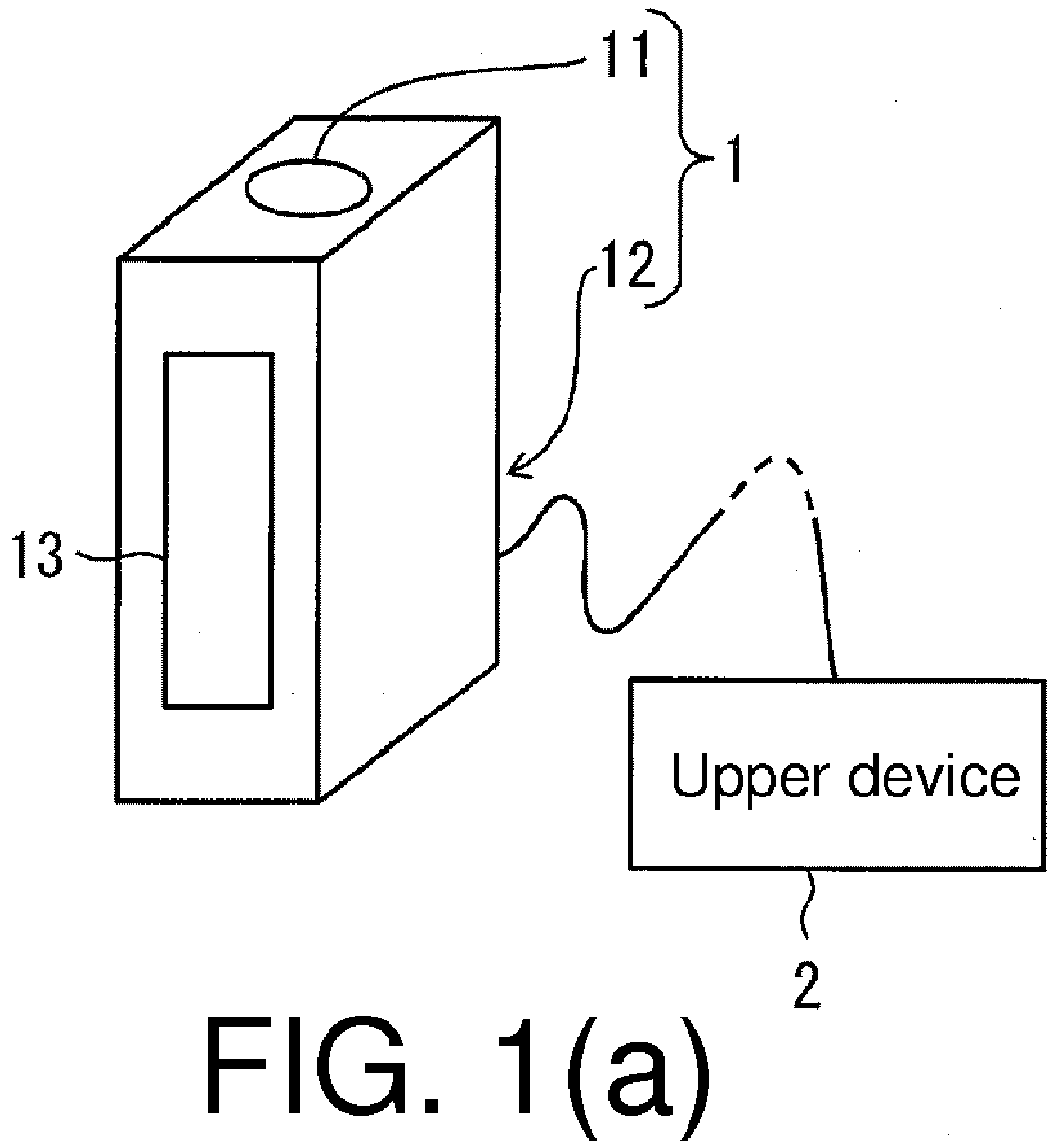
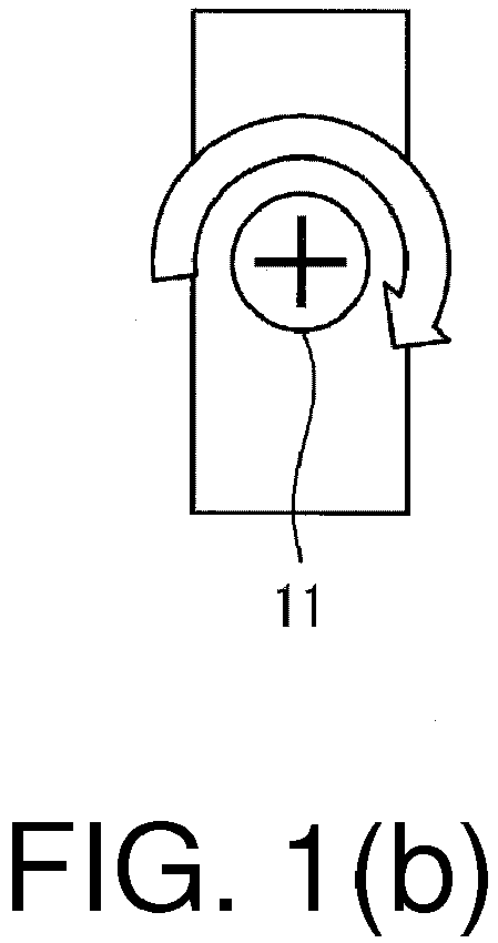
- FIG. 1(a) to FIG. 1(e) are diagrams of a structure of a sensor 1 according to an embodiment of the present invention.
- FIG. 1(a) is a three-dimensional diagram of an overall structure of a sensor 1
- FIG. 1(b) is a plane diagram of a structure of an operator 11 of the sensor 1
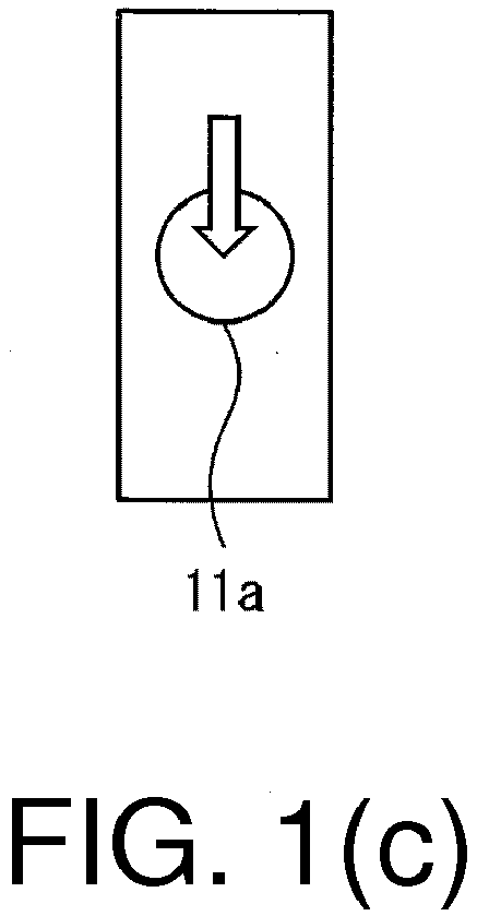
- FIG. 1(c) is a plane diagram of a structure of a varying example of the operator shown in FIG. 1(b)
- FIG. 1(d) is a side view of a structure of a communication portion 12 of the sensor
- FIG. 1(e) is a side view of a structure of a varying example of the shown in FIG. 1(d) .
- the senor 1 has an operator 11 and a communication portion 12.
- the operator 11 is disposed on a frame of the sensor 1.
- the communication portion 12 is connected with an upper device 2.
- One side of the sensor 1 is provided with a measuring portion 13 for measuring physical quantity.
- the operator 11 has a so-called "volume", and the volume is an operation moveable portion for continuously changing sensitivity of the sensor 1 through rotation.
- a VCC/communication signal/GND is input into the communication portion 12.
- the communication signal is a signal transmitted and received between the upper device 2 and the communication portion 12.
- FIG. 2 is a block diagram of a detailed structure of the sensor 1 shown in FIG. 1(a) .
- the senor 1 further has a Central Processing Unit (CPU) 14 (setting portion).
- CPU Central Processing Unit
- the CPU 14 is an operation processing block that performs processing through a CPU, and has an Analog Digital Converter (ADC) 141 and a processing portion 142.
- ADC Analog Digital Converter
- the operator 11 has a Variable Resistor (VR) 111 (operation moveable portion).
- the VR 111 is connected to the ADC 141.
- the ADC 141, the communication portion 12, an Electrically Erasable Programmable Read Only Memory (EEPROM) (registered trademark) 15 and an Application Specific Integrated Circuit (ASIC) 16 are connected on the processing portion 142.
- EEPROM Electrically Erasable Programmable Read Only Memory
- ASIC Application Specific Integrated Circuit
- the sensor 1 as described later, measures physical quantity based on a set value.
- the sensor 1 is a photoelectric sensor/proximity sensor/electrostatic capacitance sensor/ultrasonic sensors/pressure sensors/flow sensor/vibration sensor.
- the VR 111 acts as a sensitivity adjusting portion that adjusts sensitivity of the sensor 1.
- Sensitivity is the set value of the sensor 1. Moreover, a signal corresponding to the light received by the measuring portion 13 is amplified to a multiple of the "sensitivity” updated by the CPU 14. The sensor 1 judges whether amplitude of the amplified signal exceeds a threshold.
- the ADC 141 performs analog/digital (AD) conversion on the VR value.
- a numerical value of the VR value is input to the processing portion 142 from the ADC 141.
- the numerical value is a value corresponding to a rotation operation performed on the operator 11.
- the operator 11 inputs an input value corresponding to the rotation operation to the CPU 14.
- the upper device 2 sends an input value to the communication portion 12.
- Communication between the upper device 2 and the communication portion 12 is communication on a physical layer of an Open System Interconnection (OSI) reference model.
- the communication signal in the communication is transmitted in a half duplex mode.
- OSI Open System Interconnection
- the communication portion 12 detects whether there is communication between the upper device 2 and the communication portion 12. Moreover, the communication portion 12 converts a level of the input value received, to enable the CPU 14 to perform processing.
- the communication portion 12 inputs the received input value to the CPU 14.
- the ASIC 16 acts as a sensitivity change portion that changes the sensitivity of the sensor 1.
- the processing portion 142 controls the ASIC 16, such that the ASIC 16 changes the sensitivity of the sensor 1 to an input value of any last input one of the input value generated by the operator 11 and the input value received by the communication portion 12.
- the EEPROM 15 stores the sensitivity changed by the ASIC 16.
- FIG. 3(a) and FIG. 3(b) are diagrams of changes of the VR value of the VR 111 of the operator 11 of the sensor 1 shown in FIG. 2 .
- FIG. 3(a) is a chart
- FIG. 3(b) is a table corresponding to the chart shown in FIG. 3(a) .
- the ADC 141 performs AD conversion on the VR value with a sampling cycle of 30 ms.
- the horizontal axis of the chart of FIG. 3(a) represents time.
- the vertical axis of the chart represents a VR value (volume AD value) converted by the ADC 141 to a digital value.
- the unit of the digital value is set as digit.
- the processing portion 142 determines, based on the next starting reference, the VR value of Time a as a reference value, and starts counting the number of sampling of the VR value from Time b1 (determination starting time).
- an absolute value of a difference between the VR value of Time b1 and the VR value of Time a prior to a sampling cycle compared with Time b1 is equal to or above 50 digit.
- the processing portion 142 counts the VR value of Time b1 as first time.
- "50 digit" in the starting reference is a quantity that an absolute value of a difference between the input value and the reference value when the input value generated by the VR 111 of the operator 11 changes due to factors (e.g., electrical noise) other than the operation of the operator 11.
- the specified value is not limited to 50 digit, as long as it is set as a specified valued other than the input value not preferably updated to the sensitivity of the sensor 1.
- the processing portion 142 based on the next increase reference, increases the number of sampling of the VR value after Time b1.
- An absolute value of a difference between the VR value of Time b2 and the VR value of Time a set as a reference value is equal to or above 50 digit. So is that from Time b3 to Time b6. Therefore, the processing 142 counts VR values from Time b2 to Time b6 as twice to six times respectively.
- the processing portion 142 stops counting the number of sampling, and sets the number of sampling as 0.
- the processing portion 142 updates the VR value to the sensitivity of the sensor 1 from the time when the number of sampling reaches 6 (specified number).
- the number of sampling "6" is not limited to value, as long as it is the number of times the ADC 141 of the CPU 14 samples the VR value within an appropriate period of continuation of the operation of the operator 11.
- the appropriate period of continuation of the operation of the operator 11 as a volume is at least 150 milliseconds (hereinafter referred to as "ms"), and the sampling cycle of the ADC 141 of the CPU 14 is 30 ms.
- the processing portion 142 of the CPU 14 can be prevented from updating the input value, which is not preferably updated to the sensitivity of the sensor 1 in the input value generated by the VR 111 of the operator 11, to the sensitivity.
- the processing portion 142 at a time after the number of sampling reaches 6, when a period during which the variation amplitude of the VR value is below 20 digit (specified variation amplitude) lasts 2 or more than 2 s (fixed period), stops updating the VR value to the sensitivity of the sensor 1.
- the number of sampling reaches 6 at Time b6.
- the period during which the variation of the VR value is below 20 digit lasts 2010 ms.
- the period during which the variation of the VR value is below 20 digit lasts 2 or more than 2 s.
- the processing portion 142 stops updating the VR value to the sensitivity of the sensor 1 at Time f.
- the “2 s" is not limited to the value, as long as it is an appropriate period from when the operator 11 is operated till next time the operator is operated.
- the "20 digit” is not limited to the value, as long as it is appropriate variation amplitude of the VR value from when the operation of the operator 11 stops till after the VR value is converged to a fixed value.
- the processing portion 142 of the CPU 14 can be prevented from the input value which is not preferably updated to the sensitivity of the sensor 1 in the input value generated by the VR 111 of the operator 11 (e.g., an input value varying significantly instantly) to sensitivity.
- the CPU 14 of the sensor 1 updates the sensitivity of the sensor 1 to a later input one of the following (1) and (2).
- the sensor 1 can measure physical quantity based on the sensitivity without receiving an instruction indicating that which of (1) and (2) should be adopted from the user of the sensor 1.
- the set value needs to be updated to any of multiple input values.
- the user when the sensor does not operate according to the user's assumption, preferably, the user, for example, performs an operation on an operator disposed in a frame of the sensor, so as to be able to update the set value near the sensor.
- the behavior of the sensor has to be changed in a manner of omitting any of the multiple input values. Therefore, users of the former sensor cannot use the sensor efficiently.
- the sensor 1 of this embodiment can measure physical quantity based on the sensitivity as the set value without receiving an instruction indicating that which of the multiple input values should be adopted from the user of the sensor 1.
- the user of the sensor 1 can use the sensor more efficiently than before.
- the operation accepted by the operator is a mechanical operation.
- the so-called “mechanical operation”, for example, is the following listed.
- the operator 11 may also be a button 11 a that causes the CPU 14 to update the sensitivity of the sensor 1 by press-down.
- the operator 11 may also be a teaching button 11a that causes the CPU 14 to automatically optimize the sensitivity of the sensor 1 by press-down.
- the operator 11 may also be a button 11a that increases/decreases the sensitivity of the sensor 1.
- the button 11a even if the button 11a is pressed down, the appearance may not change. Hence, the user of the sensor 1 cannot confirm how the CPU 14 updates the sensitivity of the sensor 1. Moreover, for example, when the sensor 1 does not operate according to the user's assumption, it is difficult for the user to operate the button 11a to update the sensitivity of the sensor 1 near the sensor 1.
- the senor 1 has a display device that displays the sensitivity (especially when the operator 11 is a button that increases/decreases the sensitivity of the sensor 1).
- the operation input value can be generated from a VR value corresponding to a configuration angle of the volume by rotating the volume.
- the sensitivity of the sensor 1 is updated immediately.
- the appearance of the operator 11 changes according to the configuration angle of the volume.
- the user can discriminate the sensitivity updated for the sensor 1.
- the sensor 1 does not need to have a display device that displays the updated sensitivity. Therefore, the sensor 1 can be miniaturized.
- the operator 11 of the sensor 1 can also have an operation movable portion whose configuration position changes through a user's mechanical operation. At this point, the operation input value is the configuration position of the operation movable portion.
- the ADC 141 when the sampling cycle of the ADC 141 is low, even if the absolute value of the difference between the VR value and the reference value is equal to or above 50 digit, the ADC 141 sometimes may still sample a VR value an absolute value of a difference between which and a reference value is less than the specified value if the sampling cycle is increased, i.e., the VR value sampled within a fixed period is increased.
- the processing portion 142 may not stop counting the number of sampling, but based on the increase reference, increases the number of sampling of the VR value after Time b1.
- the CPU 14 updates the sensitivity of the sensor 1, but is not limited to this. Any parameter is ok as long as it is a parameter (set value) affecting the output value of the sensor.
- the measuring portion 13 of the sensor 1 may also be a photoelectric sensor that receives light and projects light.
- the sensor 1 amplifies intensity of the light projected by the measuring portion 13 to a multiple of the parameter updated by the CPU 14, that is, light projecting power of the sensor 1 is amplified.
- the sensor 1 judges whether amplitude of a signal corresponding to light quantity of the light received by the measuring portion 13 exceeds a threshold.
- the senor 1 may also be a photoelectric sensor that judges a distance between the object and the sensor 1 is closer or farther than the reference distance, a Time of Flight (TOF) measuring manner/phase difference manner/triangular ranging manner/Pseudo Noise (PN) code manner and other manners.
- TOF Time of Flight
- PN Pseudo Noise
- the sensor 1 receives light reflected from the object through the measuring portion 13, so as to measure the distance between the object and the sensor 1, and judges whether the distance exceeds a threshold (set value) updated by the CPU 14.
- a measuring method described as follows is also included in the present invention.
- the measuring method measures physical quantity based on a set value such as sensitivity, including: an operating step of, as shown by the operator 11 in FIG. 2 , accepting a mechanical operation of a user, and generating an operation input value corresponding to the operation; a communication portion of, as shown by the communication portion 12 in FIG. 2 , receiving a communication input value; and a setting step of, as shown by the CPU 14 in FIG. 2 , updating the set value of the sensor 1 to a later input one of the operation input value and the communication input value.
- a set value such as sensitivity
- a sensor system having a sensor 1 and an upper device 2 connected to a communication portion 12 of the sensor 1 is also included in the present invention.
- the senor 1 may also employ a structure of controlling a teaching action by making high/low inputs from the upper device 2.
- the CPU 14 the communication portion 12 and the ASIC 16 may also be replaced with other elements having the same functions.
- the communication between the upper device 2 and the communication portion 12 may be wired communication and may also be wireless communication.
Landscapes
- Physics & Mathematics (AREA)
- General Physics & Mathematics (AREA)
- Engineering & Computer Science (AREA)
- Electromagnetism (AREA)
- Computer Networks & Wireless Communication (AREA)
- Radar, Positioning & Navigation (AREA)
- Remote Sensing (AREA)
- Arrangements For Transmission Of Measured Signals (AREA)
Abstract
Description
- The present invention relates to a sensor that measures physical quantity based on a set value, a sensor system having the sensor, and a measuring method that measures physical quantity based on a set value.
- In recent years, with Internet of Things (IoT) and informatization of manufacturing apparatuses/devices, productivity, quality, reliability and the like are improved, and market input of optimal-quantity goods in a shorter period is advancing. For example, a sensor as the lowest layer is also networked, which seeks efficiency of start, maintenance and care of apparatuses, or collects real-time information of the sensor as big data and performs feedback and control, thereby improving the quality and the like.
- In the past, in the case of a sensor not connected with an upper device, start, maintenance and care of devices are performed with the following methods such as (1) and (2).
- (1) A volume installed to a frame is rotated, so as to continuously change the sensitivity to be set as an optimal value.
- (2) A teaching button installed to a frame is pressed down, so as to automatically set the sensitivity as an optimal value.
- Moreover, in the case of a sensor connected with an upper device, the value of the sensitivity can be set freely through communication from the upper device.
-
Patent Document 1 discloses an interconnected sensor system having a network unit and multiple sensor units. - Patent Document 1:
Japanese Patent Publication Gazette No. 2010-165270 (published on July 29, 2010 - However, in the case of a sensor not connected with an upper device, each sensor has to be set directly, and the efficiency is poor in each working procedure.
- Moreover, in the case of a sensor connected with an upper device, which of the value set on the frame (described as "frame setting" later) and the value set through communication of the upper device (described as "communication setting" later) is valid is switched, after the setting is made through communication, when a fault occurs during operation, the communication setting has to be set as invalid by using the communication from the upper device once, and after the frame setting is set as valid, on-site responses are made, which is thus ineffective.
- The present invention is accomplished in view of the problem, aimed at achieving a sensor that can be used more efficiently than before.
- To solve the issue, the sensor of the present invention measures physical quantity based on a set value, the sensor including: an operator that accepts a mechanical operation of a user, and generates an operation input value corresponding to the operation; a communication portion that receives a communication input value; and a setting portion that updates the set value according to a later input one of the operation input value and the communication input value.
- In the sensor that measures physical quantity based on a set value, sometimes the set value is updated to any of multiple input values.
- In such a sensor, when the sensor does not operate according to the user's assumption, preferably, the user, for example, performs a mechanical operation on an operator disposed in a frame of the sensor, so as to be able to update the set value near the sensor.
- At this point, in the former sensor, the behavior of the sensor has to be changed in a manner of omitting any of the multiple input values. Therefore, users of the former sensor cannot use the sensor efficiently.
- On the other hand, in the sensor of the present invention, according to the structure, the setting portion updates the set values to a later input one of the following (1) and (2).
- (1) an input value generated by the operator (operation input value), and
- (2) an input value received by the communication portion (communication input value).
- Therefore, the sensor can measure physical quantity based on a set value without receiving an instruction indicating that which of (1) and (2) should be adopted from the user of the sensor.
- According to the above, the user of the sensor can use the sensor more efficiently than before.
- In addition, the so-called "updating according to a later input one" includes: the setting portion converts any input value in the operation input value and the communication input value, and updates the set value to a converted input value.
- Moreover, the setting portion's updating the set value is not limited to once. After the set value is updated, the setting portion can further update the set value to the input value input as long as any input value in the operation input value and the communication input value is input.
- Moreover, the operator may also have an operation movable portion listed in the following.
- A so-called "volume" that continuously changes the set value of the sensor by rotation
- A teaching button that automatically optimizes the set value of the sensor by press-down
- A button that increases/decreases the set value of the sensor by press-down
- Preferably, the operator includes an operation movable portion, the an operation movable portion changes a configuration angle or configuration position according to the mechanical operation of the user, and the operation input value is the configuration angle or configuration position of the operation moveable portion.
- According to the structure, the operator may generate the operation input value from the configuration angle or configuration position of the operation moveable portion through a mechanical operation of rotating or displacing the operation moveable portion. Thus, after the operation of the operation moveable portion, the set value is updated immediately.
- At this point, the appearance of the operator will change according to the configuration angle or configuration position of the operation moveable portion. Hence, the user can discriminate the updated set value. Thus, the sensor does not need to have a display device that displays the updated set value. Therefore, the sensor can be miniaturized.
- The operation moveable portion, for example, is the so-called "volume" that continuously changes the set value of the sensor by rotation. At this point, the mechanical operation is an operation of rotating the volume.
- Preferably, the setting portion samples the operation input value with a fixed sampling cycle, when an absolute value of a difference between the operation input value sampled at a determination starting time and the operation input value sampled from the determination starting time to a time prior to the sampling cycle, i.e., a reference value, is equal to or above a specified value, starts counting the number of sampling of the operation input value, when an absolute value of a difference between the operation input value sampled at a time after the determination starting time and the reference value is equal to or above the specified value, increases the number of sampling, and starts updating the set value to the operation input value at a time when the number of sampling reaches a specified number.
- According to the structure, the setting portion can be prevented from updating an operation input value which is not preferably updated to the set value in the operation input value to the set value.
- Thus, the user of the sensor can utilize the set value of communication for updating and can efficiently utilize the set value of the operator for updating.
"an operation input value which is not preferably updated to the set value" is an operation input value an absolute value of a difference between which and a reference value is less than a specified value.
"specified value" is a quantity that the absolute value of the difference between the operation input value and the reference value may change when the operation input value changes due to factors (e.g., electrical noise) other than the operation of the operator. - The so-called "the absolute value is equal to or above the specified value" refers to that the absolute value is a specified value or the absolute value exceeds the specified value. In addition, in the structure, the sensor having a structure specified as "the absolute value exceeds the specified value" is also included in the present invention.
"specified number" is the number of times the setting portion samples the operation input value within an appropriate period of continuation of the operation of the operator. - In addition, when the sampling cycle of the setting portion is low, even if the absolute value of the difference between the operation input value and the reference value is equal to or above the specified value, the setting portion sometimes may still sample an operation input value an absolute value of a difference between which and a reference value is less than the specified value if the sampling cycle is increased, i.e., the operation input value sampled within a fixed period is increased. According to the structure, the operation input value whose absolute value is less than the specified value will be omitted.
- Preferably, when the absolute value of the difference between the operation input value sampled at a time after the determination starting time and the reference value is less than the specified value, the setting portion stops the counting, and sets the number of sampling as 0.
- According to the structure, when sampling an operation input value an absolute value of a difference between which and a reference value is less than the specified value, the setting portion stops counting the number of sampling, and sets the number of sampling as 0. Hence, the setting portion can be really prevented from updating an operation input value which is not preferably updated to the set value in the operation input value to the set value.
- Preferably, if a variation of the sampled operation input value is included in a specified variation amplitude above a fixed period counted from that the number of sampling reaches the specified number, the setting portion stops the counting, and sets the number of sampling as 0.
- According to the structure, the setting portion can be really prevented from updating an operation input value which is not preferably updated to the set value in the operation input value (e.g., an operation input value varying significantly instantly) to sensitivity.
- "fixed period" is an appropriate period from when the operation is operated to next time the operation is operated.
"specified variation amplitude" is an appropriate variation amplitude from when the operation of the operator stops to after the operation input value is converged to a fixed value. - The sensor of the present invention may also further include a measuring portion that projects and receives light, and
the sensor being any photoelectric sensor of the following (1) to (3), - (1) a photoelectric sensor that amplifies a signal corresponding to light quantity of the light received by the measuring portion to a multiple of the set value updated by the setting portion, and determines whether amplitude of the signal amplified exceeds a threshold,
- (2) a photoelectric sensor that amplifies intensity of the light projected by the measuring portion to a multiple of the set value updated by the setting portion, and determines whether amplitude of a signal corresponding to light quantity of the light received by the measuring portion exceeds a threshold, and
- (3) a photoelectric sensor that receives light reflected from an object through the measuring portion, so as to measure a distance between the object and the sensor, and determines whether the distance exceeds the set value updated by the setting portion.
- According to the structure, a photoelectric sensor that can be used more efficiently than before may be achieved.
- In addition, the sensor of (3) may specifically be a photoelectric sensor that judges a distance between the object and the sensor is closer or farther than the reference distance, a Time of Flight (TOF) measuring manner/phase difference manner/triangular ranging manner/Pseudo Noise (PN) code manner and other manners.
- The sensor system of the present invention has the sensor and an upper device connected to the communication portion.
- In the sensor system having the sensor that measures physical quantity based on a set value and an upper device thereof, the upper device sometimes sends an input value to the sensor, and updates the set value of the sensor through communication.
- At this point, in the former sensor system, the behavior of the sensor has to be changed through communication in a manner of invalidating the updating of the set value of the sensor by means of communication.
- On the other hand, in the sensor system of the present invention, according to the structure, the setting portion of the sensor updates the set value to a later input one of the following (1) and (2).
- (1) an input value generated by the operator (operation input value), and
- (2) an input value received by the communication portion (communication input value).
- Therefore, the sensor can also measure physical quantity based on a set value even if the user of the sensor system does not perform the following operation. The operation is: in order to invalidate the updating of the set value of the sensor by means of communication, changing the behavior of the sensor through communication, to avoid updating (2) to the set value of the sensor.
- According to the above, the user of the sensor system can manage the sensor more efficiently than before.
- In addition, the so-called "an upper device connected to the communication portion" refers to a structure where the upper device and the communication portion conduct communication therebtween. The communication may be wired communication and may also be wireless communication.
- The measuring method of the present invention measures physical quantity based on a set value, the measuring method including: an operating step of accepting a mechanical operation of a user, and generating an operation input value corresponding to the operation; a communication portion of receiving a communication input value; and a setting step of updating the set value to a later input one of the operation input value and the communication input value.
- According to the method, in the setting step, the set value is updated to a later input one of the following (1) and (2).
- (1) an input value generated by the operator (operation input value), and
- (2) an input value received by the communication portion (communication input value).
- Therefore, even if any of (1) and (2) is not selected, the physical quantity can also be measured based on the set value.
- According to the above, the physical quantity can be measured more efficiently than before.
- The present invention produces the following effects of (1)-(3).
- (1) The user of the sensor can use the sensor more efficiently than before.
- (2) The user of the sensor system can manage the sensor more efficiently than before.
- (3) The physical quantity can be measured more efficiently than before.
-
-
FIG. 1(a) to FIG. 1(e) are various diagrams of a structure of a sensor according to an embodiment of the present invention; -
FIG. 2 is a block diagram of a detailed structure of the sensor shown inFIG. 1 ; and -
FIG. 3(a) and FIG. 3(b) are various diagrams of resistance changes of a variable resistor of an operator of the sensor shown inFIG. 2 . -
FIG. 1(a) to FIG. 1(e) are diagrams of a structure of asensor 1 according to an embodiment of the present invention.FIG. 1(a) is a three-dimensional diagram of an overall structure of asensor 1,FIG. 1(b) is a plane diagram of a structure of anoperator 11 of thesensor 1,FIG. 1(c) is a plane diagram of a structure of a varying example of the operator shown inFIG. 1(b), FIG. 1(d) is a side view of a structure of acommunication portion 12 of thesensor 1, andFIG. 1(e) is a side view of a structure of a varying example of the shown inFIG. 1(d) . - As shown in
FIG. 1(a) , thesensor 1 has anoperator 11 and acommunication portion 12. Theoperator 11 is disposed on a frame of thesensor 1. Thecommunication portion 12 is connected with anupper device 2. One side of thesensor 1 is provided with a measuringportion 13 for measuring physical quantity. - As shown in
FIG. 1(b) , theoperator 11 has a so-called "volume", and the volume is an operation moveable portion for continuously changing sensitivity of thesensor 1 through rotation. - As shown in
FIG. 1(d) , a VCC/communication signal/GND is input into thecommunication portion 12. The communication signal is a signal transmitted and received between theupper device 2 and thecommunication portion 12. -
FIG. 2 is a block diagram of a detailed structure of thesensor 1 shown inFIG. 1(a) . - As shown in
FIG. 2 , thesensor 1 further has a Central Processing Unit (CPU) 14 (setting portion). - The
CPU 14 is an operation processing block that performs processing through a CPU, and has an Analog Digital Converter (ADC) 141 and aprocessing portion 142. - The
operator 11 has a Variable Resistor (VR) 111 (operation moveable portion). TheVR 111 is connected to theADC 141. - The
ADC 141, thecommunication portion 12, an Electrically Erasable Programmable Read Only Memory (EEPROM) (registered trademark) 15 and an Application Specific Integrated Circuit (ASIC) 16 are connected on theprocessing portion 142. - The
sensor 1, as described later, measures physical quantity based on a set value. - "physical quantity", for example, is amplitude of amplitude/pressure/flow/vibration of light quantity/electrostatic capacitance/ultrasonic wave. That is, the
sensor 1, for example, is a photoelectric sensor/proximity sensor/electrostatic capacitance sensor/ultrasonic sensors/pressure sensors/flow sensor/vibration sensor. - When the
operator 11 is rotated, the resistance of the VR 111 (hereinafter referred to as "VR" value) changes. - The
VR 111 acts as a sensitivity adjusting portion that adjusts sensitivity of thesensor 1. - "Sensitivity" is the set value of the
sensor 1. Moreover, a signal corresponding to the light received by the measuringportion 13 is amplified to a multiple of the "sensitivity" updated by theCPU 14. Thesensor 1 judges whether amplitude of the amplified signal exceeds a threshold. - The
ADC 141 performs analog/digital (AD) conversion on the VR value. - A numerical value of the VR value is input to the
processing portion 142 from theADC 141. The numerical value is a value corresponding to a rotation operation performed on theoperator 11. - As stated above, the
operator 11 inputs an input value corresponding to the rotation operation to theCPU 14. - The
upper device 2 sends an input value to thecommunication portion 12. - Communication between the
upper device 2 and thecommunication portion 12 is communication on a physical layer of an Open System Interconnection (OSI) reference model. The communication signal in the communication is transmitted in a half duplex mode. - The
communication portion 12 detects whether there is communication between theupper device 2 and thecommunication portion 12. Moreover, thecommunication portion 12 converts a level of the input value received, to enable theCPU 14 to perform processing. - As stated above, the
communication portion 12 inputs the received input value to theCPU 14. - The
ASIC 16 acts as a sensitivity change portion that changes the sensitivity of thesensor 1. - The
processing portion 142 controls theASIC 16, such that theASIC 16 changes the sensitivity of thesensor 1 to an input value of any last input one of the input value generated by theoperator 11 and the input value received by thecommunication portion 12. - The
EEPROM 15 stores the sensitivity changed by theASIC 16. -
FIG. 3(a) and FIG. 3(b) are diagrams of changes of the VR value of theVR 111 of theoperator 11 of thesensor 1 shown inFIG. 2 .FIG. 3(a) is a chart, andFIG. 3(b) is a table corresponding to the chart shown inFIG. 3(a) . - As shown in
FIG. 3(a) , in an example of the embodiment, theADC 141 performs AD conversion on the VR value with a sampling cycle of 30 ms. The horizontal axis of the chart ofFIG. 3(a) represents time. The vertical axis of the chart represents a VR value (volume AD value) converted by theADC 141 to a digital value. The unit of the digital value is set as digit. - The
processing portion 142 determines, based on the next starting reference, the VR value of Time a as a reference value, and starts counting the number of sampling of the VR value from Time b1 (determination starting time). - [starting reference] An absolute value of a difference between a VR value of a certain time and a VR value (reference value) prior to a sampling cycle counted from the certain time is equal to or above 50 digit (specified value).
- As shown in
FIG. 3(b) , an absolute value of a difference between the VR value of Time b1 and the VR value of Time a prior to a sampling cycle compared with Time b1 is equal to or above 50 digit. Hence, theprocessing portion 142 counts the VR value of Time b1 as first time. - "50 digit" in the starting reference is a quantity that an absolute value of a difference between the input value and the reference value when the input value generated by the
VR 111 of theoperator 11 changes due to factors (e.g., electrical noise) other than the operation of theoperator 11. - Thus, the specified value is not limited to 50 digit, as long as it is set as a specified valued other than the input value not preferably updated to the sensitivity of the
sensor 1. - Moreover, the
processing portion 142, based on the next increase reference, increases the number of sampling of the VR value after Time b1. - [Increase reference] An absolute value of a difference between a VR value and a reference value is equal to or above 50 digit (specified value).
- An absolute value of a difference between the VR value of Time b2 and the VR value of Time a set as a reference value is equal to or above 50 digit. So is that from Time b3 to Time b6. Therefore, the processing 142 counts VR values from Time b2 to Time b6 as twice to six times respectively.
- When the
ADC 141 samples the VR value an absolute value of a difference between which and the reference value is less than 50 digit, theprocessing portion 142 stops counting the number of sampling, and sets the number of sampling as 0. - Moreover, the
processing portion 142 updates the VR value to the sensitivity of thesensor 1 from the time when the number of sampling reaches 6 (specified number). - At this point, the number of sampling "6" is not limited to value, as long as it is the number of times the
ADC 141 of theCPU 14 samples the VR value within an appropriate period of continuation of the operation of theoperator 11. - In an example of the embodiment, the appropriate period of continuation of the operation of the
operator 11 as a volume is at least 150 milliseconds (hereinafter referred to as "ms"), and the sampling cycle of theADC 141 of theCPU 14 is 30 ms. Thus, the number of sampling is 6 times (=150/30+1) including the beginning and the ending of the period. - According to the above, the
processing portion 142 of theCPU 14 can be prevented from updating the input value, which is not preferably updated to the sensitivity of thesensor 1 in the input value generated by theVR 111 of theoperator 11, to the sensitivity. - The
processing portion 142, at a time after the number of sampling reaches 6, when a period during which the variation amplitude of the VR value is below 20 digit (specified variation amplitude) lasts 2 or more than 2 s (fixed period), stops updating the VR value to the sensitivity of thesensor 1. - Specifically, the number of sampling reaches 6 at Time b6. Moreover, from Time c after Time b6 to Time f, the period during which the variation of the VR value is below 20 digit lasts 2010 ms. Hence, from Time c after Time b6 to Time e, the period during which the variation of the VR value is below 20 digit lasts 2 or more than 2 s.
- Moreover, the
processing portion 142 stops updating the VR value to the sensitivity of thesensor 1 at Time f. - The "2 s" is not limited to the value, as long as it is an appropriate period from when the
operator 11 is operated till next time the operator is operated. - The "20 digit" is not limited to the value, as long as it is appropriate variation amplitude of the VR value from when the operation of the
operator 11 stops till after the VR value is converged to a fixed value. - According to the above, the
processing portion 142 of theCPU 14 can be prevented from the input value which is not preferably updated to the sensitivity of thesensor 1 in the input value generated by theVR 111 of the operator 11 (e.g., an input value varying significantly instantly) to sensitivity. - According to this embodiment, the
CPU 14 of thesensor 1 updates the sensitivity of thesensor 1 to a later input one of the following (1) and (2). - (1) an input value generated by the operator 11 (operation input value), and
- (2) an input value received by the communication portion 12 (communication input value).
- Therefore, the
sensor 1 can measure physical quantity based on the sensitivity without receiving an instruction indicating that which of (1) and (2) should be adopted from the user of thesensor 1. - In the sensor that measures physical quantity based on a set value such as sensitivity, sometimes the set value needs to be updated to any of multiple input values.
- In such a sensor, when the sensor does not operate according to the user's assumption, preferably, the user, for example, performs an operation on an operator disposed in a frame of the sensor, so as to be able to update the set value near the sensor.
- At this point, in the former sensor, the behavior of the sensor has to be changed in a manner of omitting any of the multiple input values. Therefore, users of the former sensor cannot use the sensor efficiently.
- On the other hand, the
sensor 1 of this embodiment can measure physical quantity based on the sensitivity as the set value without receiving an instruction indicating that which of the multiple input values should be adopted from the user of thesensor 1. - Thus, the user of the
sensor 1 can use the sensor more efficiently than before. - The operation accepted by the operator is a mechanical operation. The so-called "mechanical operation", for example, is the following listed.
- A rotation operation of rotating a volume for continuously changing the sensitivity of the
sensor 1 - A operation of pressing down a teaching button that automatically optimizes the sensitivity of the
sensor 1 - A operation of pressing down a button that increases/decreases the sensitivity of the
sensor 1 - As shown in
FIG. 1(c) , theoperator 11 may also be abutton 11 a that causes theCPU 14 to update the sensitivity of thesensor 1 by press-down. Specifically, theoperator 11 may also be ateaching button 11a that causes theCPU 14 to automatically optimize the sensitivity of thesensor 1 by press-down. Moreover, theoperator 11 may also be abutton 11a that increases/decreases the sensitivity of thesensor 1. - However, even if the
button 11a is pressed down, the appearance may not change. Hence, the user of thesensor 1 cannot confirm how theCPU 14 updates the sensitivity of thesensor 1. Moreover, for example, when thesensor 1 does not operate according to the user's assumption, it is difficult for the user to operate thebutton 11a to update the sensitivity of thesensor 1 near thesensor 1. - At this point, preferably, the
sensor 1 has a display device that displays the sensitivity (especially when theoperator 11 is a button that increases/decreases the sensitivity of the sensor 1). - On the other hand, if the
operator 11 of thesensor 1 is the button shown inFIG. 1(b) , the operation input value can be generated from a VR value corresponding to a configuration angle of the volume by rotating the volume. Thus, after the operation of the button, the sensitivity of thesensor 1 is updated immediately. - At this point, the appearance of the
operator 11 changes according to the configuration angle of the volume. Hence, the user can discriminate the sensitivity updated for thesensor 1. Thus, thesensor 1 does not need to have a display device that displays the updated sensitivity. Therefore, thesensor 1 can be miniaturized. - In addition, the
operator 11 of thesensor 1 can also have an operation movable portion whose configuration position changes through a user's mechanical operation. At this point, the operation input value is the configuration position of the operation movable portion. - In the structure, when the sampling cycle of the
ADC 141 is low, even if the absolute value of the difference between the VR value and the reference value is equal to or above 50 digit, theADC 141 sometimes may still sample a VR value an absolute value of a difference between which and a reference value is less than the specified value if the sampling cycle is increased, i.e., the VR value sampled within a fixed period is increased. - At this point, the
processing portion 142 may not stop counting the number of sampling, but based on the increase reference, increases the number of sampling of the VR value after Time b1. - In the structure, the
CPU 14 updates the sensitivity of thesensor 1, but is not limited to this. Any parameter is ok as long as it is a parameter (set value) affecting the output value of the sensor. - Moreover, the measuring
portion 13 of thesensor 1 may also be a photoelectric sensor that receives light and projects light. For example, thesensor 1 amplifies intensity of the light projected by the measuringportion 13 to a multiple of the parameter updated by theCPU 14, that is, light projecting power of thesensor 1 is amplified. Moreover, thesensor 1 judges whether amplitude of a signal corresponding to light quantity of the light received by the measuringportion 13 exceeds a threshold. - Moreover, the
sensor 1 may also be a photoelectric sensor that judges a distance between the object and thesensor 1 is closer or farther than the reference distance, a Time of Flight (TOF) measuring manner/phase difference manner/triangular ranging manner/Pseudo Noise (PN) code manner and other manners. - At this point, the
sensor 1 receives light reflected from the object through the measuringportion 13, so as to measure the distance between the object and thesensor 1, and judges whether the distance exceeds a threshold (set value) updated by theCPU 14. - A measuring method described as follows is also included in the present invention. The measuring method measures physical quantity based on a set value such as sensitivity, including: an operating step of, as shown by the
operator 11 inFIG. 2 , accepting a mechanical operation of a user, and generating an operation input value corresponding to the operation; a communication portion of, as shown by thecommunication portion 12 inFIG. 2 , receiving a communication input value; and a setting step of, as shown by theCPU 14 inFIG. 2 , updating the set value of thesensor 1 to a later input one of the operation input value and the communication input value. - As shown in
FIG. 1(a) , a sensor system having asensor 1 and anupper device 2 connected to acommunication portion 12 of thesensor 1 is also included in the present invention. - As shown in
FIG. 1(e) , thesensor 1 may also employ a structure of controlling a teaching action by making high/low inputs from theupper device 2. - Moreover, in the constitutive elements of the
sensor 1, theCPU 14, thecommunication portion 12 and theASIC 16 may also be replaced with other elements having the same functions. - Moreover, the communication between the
upper device 2 and thecommunication portion 12 may be wired communication and may also be wireless communication. - The present invention is not limited to the various implementations, various changes can be made within the scope indicated in the claims, and implementations obtained by properly combining technical components disclosed in different implementations respectively are also included in the technical scope of the present invention.
Claims (8)
- A sensor (1), measuring physical quantity based on a set value, wherein the sensor (1) comprises:an operator (11) that accepts a mechanical operation of a user, and generates an operation input value corresponding to the operation;a communication portion (12) that receives a communication input value; anda setting portion (14) that updates the set value according to a later input one of the operation input value and the communication input value.
- The sensor (1) according to claim 1, wherein
the operator (11) comprises an operation moveable portion (111), the operation moveable portion (111) changing a configuration angle or configuration position according to the mechanical operation of the user, and
the operation input value is the configuration angle or configuration position of the operation moveable portion (111). - The sensor (1) according to claim 1 or 2, wherein
the setting portion (14) samples the operation input value with a fixed sampling cycle,
when an absolute value of a difference between the operation input value sampled at a determination starting time and the operation input value sampled from the determination starting time to a time prior to the sampling cycle, i.e., a reference value, is equal to or above a specified value, starts counting the number of sampling of the operation input value,
when an absolute value of a difference between the operation input value sampled at a time after the determination starting time and the reference value is equal to or above the specified value, increases the number of sampling, and
starts updating the set value to the operation input value at a time when the number of sampling reaches a specified number. - The sensor (1) according to claim 3, wherein
when the absolute value of the difference between the operation input value sampled at a time after the determination starting time and the reference value is less than the specified value, the setting portion (14) stops the counting, and sets the number of sampling as 0. - The sensor (1) according to claim 3 or 4, wherein
if a variation of the sampled operation input value is comprised in a specified variation amplitude above a fixed period counted from that the number of sampling reaches the specified number, the setting portion (14) stops the counting, and sets the number of sampling as 0. - The sensor (1) according to any of claims 1 to 5, further comprising:a measuring portion (13) that projects and receives light, andthe sensor (1) being any photoelectric sensor of the following (1) to (3),(1) a photoelectric sensor that amplifies a signal corresponding to light quantity of the light received by the measuring portion (13) to a multiple of the set value updated by the setting portion (14), and determines whether amplitude of the signal amplified exceeds a threshold,(2) a photoelectric sensor that amplifies intensity of the light projected by the measuring portion (13) to a multiple of the set value updated by the setting portion (14), and determines whether amplitude of a signal corresponding to light quantity of the light received by the measuring portion (13) exceeds a threshold, and(3) a photoelectric sensor that receives light reflected from an object through the measuring portion (13), so as to measure a distance between the object and the sensor (1), and determines whether the distance exceeds the set value updated by the setting portion (14).
- A sensor system, comprising:the sensor (1) according to any of claims 1 to 6; andan upper device (2) connected to the communication portion (12).
- A measuring method, measuring physical quantity based on a set value, wherein the measuring method comprises:an operating step of accepting a mechanical operation of a user, and generating an operation input value corresponding to the operation;a communication step of receiving a communication input value; anda setting step of updating the set value to a later input one of the operation input value and the communication input value.
Applications Claiming Priority (1)
| Application Number | Priority Date | Filing Date | Title |
|---|---|---|---|
| JP2016009783A JP6459991B2 (en) | 2016-01-21 | 2016-01-21 | Sensor, sensor system, and measurement method |
Publications (2)
| Publication Number | Publication Date |
|---|---|
| EP3196596A1 true EP3196596A1 (en) | 2017-07-26 |
| EP3196596B1 EP3196596B1 (en) | 2024-09-18 |
Family
ID=57984750
Family Applications (1)
| Application Number | Title | Priority Date | Filing Date |
|---|---|---|---|
| EP16203946.5A Active EP3196596B1 (en) | 2016-01-21 | 2016-12-14 | Sensor, sensor system and measuring method |
Country Status (4)
| Country | Link |
|---|---|
| US (1) | US10598772B2 (en) |
| EP (1) | EP3196596B1 (en) |
| JP (1) | JP6459991B2 (en) |
| CN (1) | CN106989770B (en) |
Families Citing this family (2)
| Publication number | Priority date | Publication date | Assignee | Title |
|---|---|---|---|---|
| JP6950373B2 (en) * | 2017-08-31 | 2021-10-13 | オムロン株式会社 | Operating device and X-ray imaging unit |
| CN117572022A (en) * | 2023-11-21 | 2024-02-20 | 四川长虹新网科技有限责任公司 | An acceleration sensor threshold automatic calibration method, device, monitoring system, electronic equipment and computer-readable storage medium |
Citations (4)
| Publication number | Priority date | Publication date | Assignee | Title |
|---|---|---|---|---|
| JP2002171162A (en) * | 2000-11-30 | 2002-06-14 | Omron Corp | Photoelectric sensor and method for adjusting sensitivity of photoelectric sensor |
| JP2010165270A (en) | 2009-01-19 | 2010-07-29 | Keyence Corp | Continuously-arranged sensor system, network unit, and sensor unit |
| US20140324389A1 (en) * | 2013-04-29 | 2014-10-30 | Emerson Electric (Us) Holding Corporation (Chile) Limitada | Dynamic transducer with digital output and method for use |
| EP2910981A2 (en) * | 2014-02-23 | 2015-08-26 | Omron Corporation | Photoelectric sensor with sensitivity parameter adjusting means |
Family Cites Families (4)
| Publication number | Priority date | Publication date | Assignee | Title |
|---|---|---|---|---|
| JP3669352B2 (en) * | 2002-09-11 | 2005-07-06 | オムロン株式会社 | Photoelectric sensor |
| JP5483211B2 (en) * | 2011-09-30 | 2014-05-07 | 横河電機株式会社 | Field device setting method and field device setting system |
| JP6264934B2 (en) * | 2014-02-23 | 2018-01-24 | オムロン株式会社 | Photoelectric sensor |
| WO2016138484A1 (en) * | 2015-02-26 | 2016-09-01 | Kazanchian Armen E | Reliable synchronized delivery on multiple receivers with high accuracy |
-
2016
- 2016-01-21 JP JP2016009783A patent/JP6459991B2/en active Active
- 2016-12-14 EP EP16203946.5A patent/EP3196596B1/en active Active
- 2016-12-15 US US15/379,498 patent/US10598772B2/en active Active
- 2016-12-16 CN CN201611176100.5A patent/CN106989770B/en active Active
Patent Citations (4)
| Publication number | Priority date | Publication date | Assignee | Title |
|---|---|---|---|---|
| JP2002171162A (en) * | 2000-11-30 | 2002-06-14 | Omron Corp | Photoelectric sensor and method for adjusting sensitivity of photoelectric sensor |
| JP2010165270A (en) | 2009-01-19 | 2010-07-29 | Keyence Corp | Continuously-arranged sensor system, network unit, and sensor unit |
| US20140324389A1 (en) * | 2013-04-29 | 2014-10-30 | Emerson Electric (Us) Holding Corporation (Chile) Limitada | Dynamic transducer with digital output and method for use |
| EP2910981A2 (en) * | 2014-02-23 | 2015-08-26 | Omron Corporation | Photoelectric sensor with sensitivity parameter adjusting means |
Also Published As
| Publication number | Publication date |
|---|---|
| CN106989770B (en) | 2019-10-11 |
| US20170212227A1 (en) | 2017-07-27 |
| US10598772B2 (en) | 2020-03-24 |
| EP3196596B1 (en) | 2024-09-18 |
| JP2017130096A (en) | 2017-07-27 |
| CN106989770A (en) | 2017-07-28 |
| JP6459991B2 (en) | 2019-01-30 |
Similar Documents
| Publication | Publication Date | Title |
|---|---|---|
| CN111083625B (en) | Microphone performance test method, test management equipment and test system | |
| US9170095B1 (en) | Distance detection device and method including dynamically adjusted frame rate | |
| JP5179602B2 (en) | Measurement parameter input control apparatus and method | |
| JP6664225B2 (en) | Information processing apparatus, control method therefor, and program | |
| EP3196596B1 (en) | Sensor, sensor system and measuring method | |
| KR20220159629A (en) | Robot cleaner and control method thereof | |
| CN206657470U (en) | With the rod-type pump controller that oil pumper is used together | |
| CN103018594A (en) | Capacitive touch screen testing method and system, and electronic equipment | |
| CN105135611B (en) | A kind of air conditioning control method and intelligent watch | |
| CN106525330A (en) | Calibration control method of pressure sensor | |
| CN112558189B (en) | A method for detecting rainfall, a device for detecting rainfall, a vehicle, and a readable storage medium | |
| CN102566822A (en) | Automatic calibration method for touch screen | |
| US10365729B2 (en) | Vibration-based trajectory calculation of a freely-guided device | |
| CN114325104A (en) | Rock and ore sample impedance remote measurement system and method | |
| CN109444530A (en) | The method of sampling and device of AC signal | |
| CN108495232B (en) | Method and device for adjusting microphone volume, microphone and storage medium | |
| CN114296549B (en) | Wearable device control method, device, wearable device and medium | |
| CN108317696A (en) | Control method, device and the computer readable storage medium of air conditioner | |
| CN103869830B (en) | A kind of control method using real time system control ellipsometer and real-time system | |
| CN110310468A (en) | Apparatus debugging method, client and equipment | |
| CN113204288A (en) | Knob speed determination method, device and system and video processing equipment | |
| CN114097213A (en) | Portable control device for controlling motion sensors | |
| CN115655456A (en) | Method, device, equipment and storage medium for vibration testing and analysis | |
| TW201901388A (en) | Touch processing device, method and system | |
| JP2020041864A (en) | Waveform data compression device, waveform data compression system, waveform data compression method, and program |
Legal Events
| Date | Code | Title | Description |
|---|---|---|---|
| PUAI | Public reference made under article 153(3) epc to a published international application that has entered the european phase |
Free format text: ORIGINAL CODE: 0009012 |
|
| STAA | Information on the status of an ep patent application or granted ep patent |
Free format text: STATUS: REQUEST FOR EXAMINATION WAS MADE |
|
| 17P | Request for examination filed |
Effective date: 20161214 |
|
| AK | Designated contracting states |
Kind code of ref document: A1 Designated state(s): AL AT BE BG CH CY CZ DE DK EE ES FI FR GB GR HR HU IE IS IT LI LT LU LV MC MK MT NL NO PL PT RO RS SE SI SK SM TR |
|
| AX | Request for extension of the european patent |
Extension state: BA ME |
|
| RBV | Designated contracting states (corrected) |
Designated state(s): AL AT BE BG CH CY CZ DE DK EE ES FI FR GB GR HR HU IE IS IT LI LT LU LV MC MK MT NL NO PL PT RO RS SE SI SK SM TR |
|
| R17P | Request for examination filed (corrected) |
Effective date: 20161214 |
|
| STAA | Information on the status of an ep patent application or granted ep patent |
Free format text: STATUS: EXAMINATION IS IN PROGRESS |
|
| 17Q | First examination report despatched |
Effective date: 20210609 |
|
| GRAP | Despatch of communication of intention to grant a patent |
Free format text: ORIGINAL CODE: EPIDOSNIGR1 |
|
| STAA | Information on the status of an ep patent application or granted ep patent |
Free format text: STATUS: GRANT OF PATENT IS INTENDED |
|
| INTG | Intention to grant announced |
Effective date: 20240426 |
|
| GRAS | Grant fee paid |
Free format text: ORIGINAL CODE: EPIDOSNIGR3 |
|
| GRAA | (expected) grant |
Free format text: ORIGINAL CODE: 0009210 |
|
| STAA | Information on the status of an ep patent application or granted ep patent |
Free format text: STATUS: THE PATENT HAS BEEN GRANTED |
|
| AK | Designated contracting states |
Kind code of ref document: B1 Designated state(s): AL AT BE BG CH CY CZ DE DK EE ES FI FR GB GR HR HU IE IS IT LI LT LU LV MC MK MT NL NO PL PT RO RS SE SI SK SM TR |
|
| REG | Reference to a national code |
Ref country code: GB Ref legal event code: FG4D |
|
| REG | Reference to a national code |
Ref country code: CH Ref legal event code: EP |
|
| REG | Reference to a national code |
Ref country code: DE Ref legal event code: R096 Ref document number: 602016089434 Country of ref document: DE |
|
| REG | Reference to a national code |
Ref country code: IE Ref legal event code: FG4D |
|
| REG | Reference to a national code |
Ref country code: LT Ref legal event code: MG9D |
|
| PG25 | Lapsed in a contracting state [announced via postgrant information from national office to epo] |
Ref country code: NO Free format text: LAPSE BECAUSE OF FAILURE TO SUBMIT A TRANSLATION OF THE DESCRIPTION OR TO PAY THE FEE WITHIN THE PRESCRIBED TIME-LIMIT Effective date: 20241218 |
|
| PG25 | Lapsed in a contracting state [announced via postgrant information from national office to epo] |
Ref country code: GR Free format text: LAPSE BECAUSE OF FAILURE TO SUBMIT A TRANSLATION OF THE DESCRIPTION OR TO PAY THE FEE WITHIN THE PRESCRIBED TIME-LIMIT Effective date: 20241219 Ref country code: FI Free format text: LAPSE BECAUSE OF FAILURE TO SUBMIT A TRANSLATION OF THE DESCRIPTION OR TO PAY THE FEE WITHIN THE PRESCRIBED TIME-LIMIT Effective date: 20240918 |
|
| PG25 | Lapsed in a contracting state [announced via postgrant information from national office to epo] |
Ref country code: BG Free format text: LAPSE BECAUSE OF FAILURE TO SUBMIT A TRANSLATION OF THE DESCRIPTION OR TO PAY THE FEE WITHIN THE PRESCRIBED TIME-LIMIT Effective date: 20240918 |
|
| PG25 | Lapsed in a contracting state [announced via postgrant information from national office to epo] |
Ref country code: LV Free format text: LAPSE BECAUSE OF FAILURE TO SUBMIT A TRANSLATION OF THE DESCRIPTION OR TO PAY THE FEE WITHIN THE PRESCRIBED TIME-LIMIT Effective date: 20240918 |
|
| PG25 | Lapsed in a contracting state [announced via postgrant information from national office to epo] |
Ref country code: HR Free format text: LAPSE BECAUSE OF FAILURE TO SUBMIT A TRANSLATION OF THE DESCRIPTION OR TO PAY THE FEE WITHIN THE PRESCRIBED TIME-LIMIT Effective date: 20240918 |
|
| REG | Reference to a national code |
Ref country code: NL Ref legal event code: MP Effective date: 20240918 |
|
| PG25 | Lapsed in a contracting state [announced via postgrant information from national office to epo] |
Ref country code: RS Free format text: LAPSE BECAUSE OF FAILURE TO SUBMIT A TRANSLATION OF THE DESCRIPTION OR TO PAY THE FEE WITHIN THE PRESCRIBED TIME-LIMIT Effective date: 20241218 |
|
| PG25 | Lapsed in a contracting state [announced via postgrant information from national office to epo] |
Ref country code: RS Free format text: LAPSE BECAUSE OF FAILURE TO SUBMIT A TRANSLATION OF THE DESCRIPTION OR TO PAY THE FEE WITHIN THE PRESCRIBED TIME-LIMIT Effective date: 20241218 Ref country code: NO Free format text: LAPSE BECAUSE OF FAILURE TO SUBMIT A TRANSLATION OF THE DESCRIPTION OR TO PAY THE FEE WITHIN THE PRESCRIBED TIME-LIMIT Effective date: 20241218 Ref country code: LV Free format text: LAPSE BECAUSE OF FAILURE TO SUBMIT A TRANSLATION OF THE DESCRIPTION OR TO PAY THE FEE WITHIN THE PRESCRIBED TIME-LIMIT Effective date: 20240918 Ref country code: HR Free format text: LAPSE BECAUSE OF FAILURE TO SUBMIT A TRANSLATION OF THE DESCRIPTION OR TO PAY THE FEE WITHIN THE PRESCRIBED TIME-LIMIT Effective date: 20240918 Ref country code: GR Free format text: LAPSE BECAUSE OF FAILURE TO SUBMIT A TRANSLATION OF THE DESCRIPTION OR TO PAY THE FEE WITHIN THE PRESCRIBED TIME-LIMIT Effective date: 20241219 Ref country code: FI Free format text: LAPSE BECAUSE OF FAILURE TO SUBMIT A TRANSLATION OF THE DESCRIPTION OR TO PAY THE FEE WITHIN THE PRESCRIBED TIME-LIMIT Effective date: 20240918 Ref country code: BG Free format text: LAPSE BECAUSE OF FAILURE TO SUBMIT A TRANSLATION OF THE DESCRIPTION OR TO PAY THE FEE WITHIN THE PRESCRIBED TIME-LIMIT Effective date: 20240918 |
|
| REG | Reference to a national code |
Ref country code: AT Ref legal event code: MK05 Ref document number: 1725051 Country of ref document: AT Kind code of ref document: T Effective date: 20240918 |
|
| PG25 | Lapsed in a contracting state [announced via postgrant information from national office to epo] |
Ref country code: NL Free format text: LAPSE BECAUSE OF FAILURE TO SUBMIT A TRANSLATION OF THE DESCRIPTION OR TO PAY THE FEE WITHIN THE PRESCRIBED TIME-LIMIT Effective date: 20240918 |
|
| PG25 | Lapsed in a contracting state [announced via postgrant information from national office to epo] |
Ref country code: IS Free format text: LAPSE BECAUSE OF FAILURE TO SUBMIT A TRANSLATION OF THE DESCRIPTION OR TO PAY THE FEE WITHIN THE PRESCRIBED TIME-LIMIT Effective date: 20250118 Ref country code: PT Free format text: LAPSE BECAUSE OF FAILURE TO SUBMIT A TRANSLATION OF THE DESCRIPTION OR TO PAY THE FEE WITHIN THE PRESCRIBED TIME-LIMIT Effective date: 20250120 |
|
| PG25 | Lapsed in a contracting state [announced via postgrant information from national office to epo] |
Ref country code: RO Free format text: LAPSE BECAUSE OF FAILURE TO SUBMIT A TRANSLATION OF THE DESCRIPTION OR TO PAY THE FEE WITHIN THE PRESCRIBED TIME-LIMIT Effective date: 20240918 Ref country code: SM Free format text: LAPSE BECAUSE OF FAILURE TO SUBMIT A TRANSLATION OF THE DESCRIPTION OR TO PAY THE FEE WITHIN THE PRESCRIBED TIME-LIMIT Effective date: 20240918 |
|
| PG25 | Lapsed in a contracting state [announced via postgrant information from national office to epo] |
Ref country code: ES Free format text: LAPSE BECAUSE OF FAILURE TO SUBMIT A TRANSLATION OF THE DESCRIPTION OR TO PAY THE FEE WITHIN THE PRESCRIBED TIME-LIMIT Effective date: 20240918 |
|
| PG25 | Lapsed in a contracting state [announced via postgrant information from national office to epo] |
Ref country code: EE Free format text: LAPSE BECAUSE OF FAILURE TO SUBMIT A TRANSLATION OF THE DESCRIPTION OR TO PAY THE FEE WITHIN THE PRESCRIBED TIME-LIMIT Effective date: 20240918 Ref country code: AT Free format text: LAPSE BECAUSE OF FAILURE TO SUBMIT A TRANSLATION OF THE DESCRIPTION OR TO PAY THE FEE WITHIN THE PRESCRIBED TIME-LIMIT Effective date: 20240918 |
|
| PG25 | Lapsed in a contracting state [announced via postgrant information from national office to epo] |
Ref country code: PL Free format text: LAPSE BECAUSE OF FAILURE TO SUBMIT A TRANSLATION OF THE DESCRIPTION OR TO PAY THE FEE WITHIN THE PRESCRIBED TIME-LIMIT Effective date: 20240918 Ref country code: CZ Free format text: LAPSE BECAUSE OF FAILURE TO SUBMIT A TRANSLATION OF THE DESCRIPTION OR TO PAY THE FEE WITHIN THE PRESCRIBED TIME-LIMIT Effective date: 20240918 |
|
| PG25 | Lapsed in a contracting state [announced via postgrant information from national office to epo] |
Ref country code: IT Free format text: LAPSE BECAUSE OF FAILURE TO SUBMIT A TRANSLATION OF THE DESCRIPTION OR TO PAY THE FEE WITHIN THE PRESCRIBED TIME-LIMIT Effective date: 20240918 Ref country code: SK Free format text: LAPSE BECAUSE OF FAILURE TO SUBMIT A TRANSLATION OF THE DESCRIPTION OR TO PAY THE FEE WITHIN THE PRESCRIBED TIME-LIMIT Effective date: 20240918 |
|
| REG | Reference to a national code |
Ref country code: DE Ref legal event code: R097 Ref document number: 602016089434 Country of ref document: DE |
|
| PG25 | Lapsed in a contracting state [announced via postgrant information from national office to epo] |
Ref country code: MC Free format text: LAPSE BECAUSE OF FAILURE TO SUBMIT A TRANSLATION OF THE DESCRIPTION OR TO PAY THE FEE WITHIN THE PRESCRIBED TIME-LIMIT Effective date: 20240918 |
|
| PG25 | Lapsed in a contracting state [announced via postgrant information from national office to epo] |
Ref country code: DK Free format text: LAPSE BECAUSE OF FAILURE TO SUBMIT A TRANSLATION OF THE DESCRIPTION OR TO PAY THE FEE WITHIN THE PRESCRIBED TIME-LIMIT Effective date: 20240918 |
|
| PLBE | No opposition filed within time limit |
Free format text: ORIGINAL CODE: 0009261 |
|
| STAA | Information on the status of an ep patent application or granted ep patent |
Free format text: STATUS: NO OPPOSITION FILED WITHIN TIME LIMIT |
|
| REG | Reference to a national code |
Ref country code: CH Ref legal event code: PL |
|
| PG25 | Lapsed in a contracting state [announced via postgrant information from national office to epo] |
Ref country code: LU Free format text: LAPSE BECAUSE OF NON-PAYMENT OF DUE FEES Effective date: 20241214 |
|
| 26N | No opposition filed |
Effective date: 20250619 |
|
| GBPC | Gb: european patent ceased through non-payment of renewal fee |
Effective date: 20241218 |
|
| PG25 | Lapsed in a contracting state [announced via postgrant information from national office to epo] |
Ref country code: SE Free format text: LAPSE BECAUSE OF FAILURE TO SUBMIT A TRANSLATION OF THE DESCRIPTION OR TO PAY THE FEE WITHIN THE PRESCRIBED TIME-LIMIT Effective date: 20240918 |
|
| REG | Reference to a national code |
Ref country code: BE Ref legal event code: MM Effective date: 20241231 |
|
| PG25 | Lapsed in a contracting state [announced via postgrant information from national office to epo] |
Ref country code: GB Free format text: LAPSE BECAUSE OF NON-PAYMENT OF DUE FEES Effective date: 20241218 Ref country code: BE Free format text: LAPSE BECAUSE OF NON-PAYMENT OF DUE FEES Effective date: 20241231 |
|
| PG25 | Lapsed in a contracting state [announced via postgrant information from national office to epo] |
Ref country code: FR Free format text: LAPSE BECAUSE OF NON-PAYMENT OF DUE FEES Effective date: 20241231 |
|
| PG25 | Lapsed in a contracting state [announced via postgrant information from national office to epo] |
Ref country code: CH Free format text: LAPSE BECAUSE OF NON-PAYMENT OF DUE FEES Effective date: 20241231 |
|
| PG25 | Lapsed in a contracting state [announced via postgrant information from national office to epo] |
Ref country code: IE Free format text: LAPSE BECAUSE OF NON-PAYMENT OF DUE FEES Effective date: 20241214 |
|
| PGFP | Annual fee paid to national office [announced via postgrant information from national office to epo] |
Ref country code: DE Payment date: 20251217 Year of fee payment: 10 |
|
| PG25 | Lapsed in a contracting state [announced via postgrant information from national office to epo] |
Ref country code: CY Free format text: LAPSE BECAUSE OF FAILURE TO SUBMIT A TRANSLATION OF THE DESCRIPTION OR TO PAY THE FEE WITHIN THE PRESCRIBED TIME-LIMIT Effective date: 20240918 |
|
| PG25 | Lapsed in a contracting state [announced via postgrant information from national office to epo] |
Ref country code: TR Free format text: LAPSE BECAUSE OF FAILURE TO SUBMIT A TRANSLATION OF THE DESCRIPTION OR TO PAY THE FEE WITHIN THE PRESCRIBED TIME-LIMIT Effective date: 20240918 |
|
| PG25 | Lapsed in a contracting state [announced via postgrant information from national office to epo] |
Ref country code: HU Free format text: LAPSE BECAUSE OF FAILURE TO SUBMIT A TRANSLATION OF THE DESCRIPTION OR TO PAY THE FEE WITHIN THE PRESCRIBED TIME-LIMIT; INVALID AB INITIO Effective date: 20161214 |
|
| PG25 | Lapsed in a contracting state [announced via postgrant information from national office to epo] |
Ref country code: SI Free format text: LAPSE BECAUSE OF FAILURE TO SUBMIT A TRANSLATION OF THE DESCRIPTION OR TO PAY THE FEE WITHIN THE PRESCRIBED TIME-LIMIT Effective date: 20240918 |
|
| PG25 | Lapsed in a contracting state [announced via postgrant information from national office to epo] |
Ref country code: LT Free format text: LAPSE BECAUSE OF FAILURE TO SUBMIT A TRANSLATION OF THE DESCRIPTION OR TO PAY THE FEE WITHIN THE PRESCRIBED TIME-LIMIT Effective date: 20240918 |