EP3196545A1 - Vehicular lamp - Google Patents
Vehicular lamp Download PDFInfo
- Publication number
- EP3196545A1 EP3196545A1 EP17152163.6A EP17152163A EP3196545A1 EP 3196545 A1 EP3196545 A1 EP 3196545A1 EP 17152163 A EP17152163 A EP 17152163A EP 3196545 A1 EP3196545 A1 EP 3196545A1
- Authority
- EP
- European Patent Office
- Prior art keywords
- light
- light source
- vehicular lamp
- deflector
- excitation light
- Prior art date
- Legal status (The legal status is an assumption and is not a legal conclusion. Google has not performed a legal analysis and makes no representation as to the accuracy of the status listed.)
- Withdrawn
Links
Images





Classifications
-
- F—MECHANICAL ENGINEERING; LIGHTING; HEATING; WEAPONS; BLASTING
- F21—LIGHTING
- F21S—NON-PORTABLE LIGHTING DEVICES; SYSTEMS THEREOF; VEHICLE LIGHTING DEVICES SPECIALLY ADAPTED FOR VEHICLE EXTERIORS
- F21S41/00—Illuminating devices specially adapted for vehicle exteriors, e.g. headlamps
- F21S41/60—Illuminating devices specially adapted for vehicle exteriors, e.g. headlamps characterised by a variable light distribution
- F21S41/67—Illuminating devices specially adapted for vehicle exteriors, e.g. headlamps characterised by a variable light distribution by acting on reflectors
- F21S41/675—Illuminating devices specially adapted for vehicle exteriors, e.g. headlamps characterised by a variable light distribution by acting on reflectors by moving reflectors
-
- F—MECHANICAL ENGINEERING; LIGHTING; HEATING; WEAPONS; BLASTING
- F21—LIGHTING
- F21S—NON-PORTABLE LIGHTING DEVICES; SYSTEMS THEREOF; VEHICLE LIGHTING DEVICES SPECIALLY ADAPTED FOR VEHICLE EXTERIORS
- F21S41/00—Illuminating devices specially adapted for vehicle exteriors, e.g. headlamps
- F21S41/10—Illuminating devices specially adapted for vehicle exteriors, e.g. headlamps characterised by the light source
- F21S41/14—Illuminating devices specially adapted for vehicle exteriors, e.g. headlamps characterised by the light source characterised by the type of light source
- F21S41/16—Laser light sources
-
- F—MECHANICAL ENGINEERING; LIGHTING; HEATING; WEAPONS; BLASTING
- F21—LIGHTING
- F21S—NON-PORTABLE LIGHTING DEVICES; SYSTEMS THEREOF; VEHICLE LIGHTING DEVICES SPECIALLY ADAPTED FOR VEHICLE EXTERIORS
- F21S41/00—Illuminating devices specially adapted for vehicle exteriors, e.g. headlamps
- F21S41/10—Illuminating devices specially adapted for vehicle exteriors, e.g. headlamps characterised by the light source
- F21S41/14—Illuminating devices specially adapted for vehicle exteriors, e.g. headlamps characterised by the light source characterised by the type of light source
- F21S41/176—Light sources where the light is generated by photoluminescent material spaced from a primary light generating element
Definitions
- the present invention relates to a vehicular lamp including a light deflector that scans light.
- a vehicular lamp to be provided in a vehicle there is such a vehicular lamp configured such that light from a light source such as a laser is scanned by a light deflector such as MEMS (Micro Electro Mechanical Systems) to draw a two-dimensional image on a fluorescent plate, and the two-dimensional image is projected forward as a light distribution pattern.
- a light source such as a laser
- MEMS Micro Electro Mechanical Systems
- a lighting system described in Japanese Patent Application Publication No. 2014-017094 is configured such that light is emitted from a light source and a light deflection mirror is rotated to scan the light, so as to change an irradiation region.
- the lighting system of JP 2014-017094 A includes a camera, and an object detecting portion that analyzes a dynamic image captured by the camera and detects an object in the dynamic image, and the lighting system is configured to mask a region where the object is detected by the object detecting portion so as to prevent the region from being irradiated with the light from the light source.
- a process of masking a predetermined region is performed so that a low beam is not projected to a far area in an opposite lane.
- the masking process is performed so that a boundary line between an irradiation region and a masked region is along a cut-off line determined by the laws and regulations.
- the cut-off line is a line inclined to a horizontal direction (a right-left direction) at about 15 degrees to 45 degrees.
- An object of the present invention is to provide a vehicular lamp that is able to perform masking along an inclined cut-off line.
- a vehicular lamp of the present invention is a vehicular lamp forming a predetermined light distribution pattern, and is characterized by including: a first light source provided to emit light forming an elliptical spot such that a longitudinal direction of the elliptical spot is inclined to a horizontal direction and a vertical direction; a first light deflector configured to scan the light emitted from the first light source; and a light system configured to form the predetermined light distribution pattern by the light scanned by the first light deflector.
- the predetermined light distribution pattern is formed by scanning the light emitted from the first light source such that the longitudinal direction of the elliptical spot is inclined relative to the horizontal direction and the vertical direction. Accordingly, a cut-off line corresponding to the inclination of the light spot can be set.
- the vehicular lamp include a second light source provided to emit light forming an elliptical spot such that a longitudinal direction of the elliptical spot is parallel to the horizontal direction or the vertical direction, and a second light deflector configured to scan the light emitted from the second light source, and it is preferable that the light system form the predetermined light distribution pattern by the light scanned by the first light deflector and the light scanned by the second light deflector.
- a range where masking along the inclined cut-off line is not required can be formed by the light configured such that the longitudinal direction of the elliptical spot is parallel to the horizontal direction or the vertical direction.
- right and left ends, a bottom end, and the like of the predetermined light distribution pattern can be formed by the light configured such that the longitudinal direction of the elliptical spot is parallel to the horizontal direction or the vertical direction.
- the light emitted from the second light source be configured such that the longitudinal direction of the elliptical spot is parallel to the horizontal direction.
- end lines of the right and left ends, the bottom end, and the like of the predetermined light distribution pattern can be formed as fine straight lines.
- the vehicular lamp include a control unit configured to control driving of the first light source, and it is preferable that: the first light source emit light so that a low beam is emitted from the vehicle; the control unit control driving of the first light source so as to form an irradiation region and a masked region where the light is turned off by a mask in a case where the light is emitted, and also the control unit set a boundary line between the irradiation region and the masked region based on information obtained externally.
- a vehicular lamp 2 includes a projection lens 3, a lens holder 4 that holds the projection lens 3, a body tube 5 attached to a rear end of the lens holder 4, and a bottom closure 6 that closes an opening on a rear side of the body tube 5.
- the vehicular lamp 2 is used as a headlight of a vehicle, for example.
- the vehicular lamp 2 includes first and second excitation light sources 11, 12, a first light deflector 13 that scans excitation light from the first excitation light source 11 two-dimensionally (in a horizontal direction and in a vertical direction), and a second light deflector 14 that scans excitation light from the second excitation light source 12 two-dimensionally.
- Driving of the first and second excitation light sources 11, 12 and the first and second light deflectors 13, 14 is controlled by a control device 16 (see FIG. 3 ), which will be described later in detail. Note that the number of excitation light sources and light deflectors is modifiable appropriately.
- the vehicular lamp 2 includes a fluorescent substance 18 (a projection body) on which a two-dimensional image corresponding to a predetermined light distribution pattern is drawn by light scanned by the first and second light deflectors 13, 14.
- the two-dimensional image drawn on the fluorescent substance 18 is projected forward by the projection lens 3.
- the first and second the excitation light sources 11, 12, the first and second light deflectors 13, 14, and the fluorescent substance 18 are placed inside the body tube 5 and are fixed by fixing members (not shown). Note that a fin for heat dissipation may be provided on an outer peripheral surface of the body tube 5.
- the first excitation light source 11 includes, for example, a semiconductor light emitting element 11a such as a laser diode (LD) that emits a laser beam in a blue range (having a luminous wavelength of 450 nm, for example) as the excitation light, and a condenser lens 11b that condenses (collimates, for example) light from the semiconductor light emitting element 11 a.
- a semiconductor light emitting element 11a such as a laser diode (LD) that emits a laser beam in a blue range (having a luminous wavelength of 450 nm, for example) as the excitation light
- a condenser lens 11b that condenses (collimates, for example) light from the semiconductor light emitting element 11 a.
- the second excitation light source 12 includes a semiconductor light emitting element 12a and a condenser lens 12b.
- the semiconductor light emitting elements 11a, 12a each may be a semiconductor light emitting element such as a laser diode that emits a laser beam in a near-ultraviolet range (having a luminous wavelength of 405 nm, for example).
- the semiconductor light emitting elements 11a, 12a each may be LED.
- the semiconductor light emitting elements 11 a, 12a each may be a laser irradiator that emits a laser beam obtained by mixing RGB.
- the first excitation light source 11 and the second excitation light source 12 emit respective laser beams toward rotation centers of respective light deflection mirrors 20 of the first and second light deflectors 13, 14, which will be described below in detail.
- the fluorescent substance 18 receives laser beams two-dimensionally scanned by the first and second light deflectors 13, 14 and converts at least part of the laser beams into light having a different wave length.
- An outer shape thereof is formed of a rectangular plate shape (or a layered shape).
- the fluorescent substance 18 is placed in the vicinity of a focus of the projection lens 3. Note that, in FIG. 2 , a thickness of the fluorescent substance 18 is illustrated in an exaggerated manner.
- a laser diode (LD) that emits a laser beam in a blue region is used as the semiconductor light emitting elements 11a, 12a of the first, second excitation light sources 11, 12, a substance that is excited by the laser beam in the blue region and emits yellow light is used as the fluorescent substance 18.
- a two-dimensional image corresponding to a predetermined light distribution pattern is drawn on the fluorescent substance 18 as a white image by the laser beam in the blue region two-dimensionally scanned by the first light deflector 13. The reason why the two-dimensional image is drawn as the white image is as follows.
- the fluorescent substance 18 emits white light (pseudo white light) due to color mixture between the laser beam in the blue region, passing through the fluorescent substance 18, and light (yellow light) emitted due to the laser beam in the blue region.
- a laser diode (LD) that emits a laser beam in a near-ultraviolet region is used as the semiconductor light emitting elements 11 a, 12a
- a substance that is excited by the laser beam in the near-ultraviolet region and emits light of three colors of red, green, and blue is used as the fluorescent substance 18.
- a two-dimensional image corresponding to a predetermined light distribution pattern is drawn on the fluorescent substance 18 as a white image by the laser beam in the near-ultraviolet region two-dimensionally scanned by the first light deflector 13. The reason why the two-dimensional image is drawn as the white image is as follows.
- the fluorescent substance 18 emits white light (pseudo white light) due to color mixture of light (light of three colors of red, green, and blue) emitted due to the laser beam in the near-ultraviolet region.
- white light may be emitted by exciting a blue fluorescent substance and a yellow fluorescent substance by a near-ultraviolet laser beam.
- the projection lens 3 is constituted by four lenses 3a to 3d, and each of the lenses 3a to 3d is held in the lens holder 4.
- Aberration (field curvature) of each of the lenses 3a to 3d is corrected so that an image surface becomes a flat surface, and chromatic aberration thereof is also corrected.
- a flat shape substance is used as the fluorescent substance 18 so as to be placed along an image surface (a flat surface).
- a focus of the projection lens 3 is positioned in the vicinity of the fluorescent substance 18. Due to the projection lens 3, it is possible to remove an influence of aberration with respect to the predetermined light distribution pattern as compared with a case where one convex lens is used. Further, since the fluorescent substance 18 has a flat shape, it is possible to easily manufacture the fluorescent substance 18 as compared with a case where the fluorescent substance 18 has a curved shape. Further, since the fluorescent substance 18 has a flat shape, it is possible to easily draw a two-dimensional image as compared with a case where the fluorescent substance 18 has a curved shape.
- the projection lens 3 may be formed as a projection lens constituted by one aspherical lens in which aberration (field curvature) is not corrected so that an image surface becomes a flat surface.
- a substance having a curved shape corresponding to the field curvature is used as the fluorescent substance 18 and is placed along the field curvature.
- the projection lens 3 projects forward the two-dimensional image drawn on the fluorescent substance 18, so as to form a low-beam distribution pattern, for example, as the predetermined light distribution pattern, on a virtual vertical screen S (placed at a position about 25 m forward from the vehicular lamp 2) directly facing to the vehicular lamp 2.
- the first and second light deflectors 13, 14 scan excitation light condensed by the condenser lenses 11b, 12b of the first and second excitation light sources 11, 12 in the horizontal direction and in the vertical direction.
- an elliptical laser spot is formed on the virtual vertical screen S.
- the first excitation light source 11 is placed so that a longitudinal direction of the elliptical laser spot is lateral (parallel to the horizontal direction) (see FIG. 6A ).
- the laser beam may be emitted so that the longitudinal direction of the elliptical shape of the laser spot is vertical (parallel to the vertical direction).
- an elliptical laser spot is formed on the virtual vertical screen S.
- the second excitation light source 12 is placed so that a longitudinal direction of the elliptical laser spot is inclined relative to the horizontal direction and the vertical direction (see FIG. 6B ).
- a longitudinal direction of the elliptical shape of the laser spot from the second excitation light source 12 is inclined at 45° relative to the horizontal direction.
- the inclination angle is modifiable appropriately, and it is preferable that the inclination angle be set so as to correspond to an angle of a cut-off line determined in the laws and regulations, which is around 15° to 45°.
- the first and second excitation light sources 11, 12 and the first and second light deflectors 13, 14 are connected to the control device 16 that controls the vehicular lamp 2 generally, so that driving thereof is controlled by the control device 16.
- the first and second light deflectors 13, 14 are MEMS scanners, for example.
- a drive system for a light deflector is roughly classified to a piezoelectric system, an electrostatic system, and a solenoid operated system, for example, but any system is usable.
- the present embodiment is described by taking a piezoelectric light deflector as a representative.
- the first light deflector 13 is a biaxial light deflector and is manufactured by use of a semiconductor process and an MEMS (Micro Electro Mechanical Systems) technique.
- the first light deflector 13 reflects light incident thereon from a given direction by the light deflection mirror 20 serving as a micromirror that rotates, so as to emit the light as reflection light (a laser beam).
- the first light deflector 13 includes a first support portion 21, and the first support portion 21 is constituted by the light deflection mirror 20, semi-annular piezoelectric actuators 23a, 23b, torsion bars 24a, 24b, and the like.
- the laser beams from the first excitation light source 11 is reflected by the light deflection mirror 20, so as to perform scanning on the virtual vertical screen S with reflection light (the laser beam) via the fluorescent substance 18 and the projection lens 3.
- the control device 16 transmits a control signal to the first light deflector 13 and the first excitation light source 11. Due to the control signal, the semi-annular piezoelectric actuators 23a, 23b of the first light deflector 13 are driven, so that the torsion bars 24a, 24b connected to the semi-annular piezoelectric actuators 23a, 23b are twisted, thereby rotating the light deflection mirror 20. Further, due to the control signal, ON/OFF and luminance of the laser beam are controlled in the first and second excitation light sources 11, 12.
- a horizontal rotating axis passing through a center of the circular light deflection mirror 20 is defined as an X-axis
- a vertical rotating axis is defined as a Y-axis.
- the X-axis is assumed the right-left direction
- the Y-axis is assumed an up-down direction
- a thickness direction of the light deflection mirror 20 is assumed a front-rear direction.
- the first light deflector 13 includes a rectangular annular second support portion 22, and a first support portion 21 is disposed in a center of the second support portion 22. Further, bellows-shaped piezoelectric actuators 31a, 31b are disposed in linear symmetry to the Y-axis passing through a center of the first support portion 21, and are connected to a side lower end of the first support portion 21 and the second support portion 22. Note that, in FIG. 3 , the first and second the support portions 21, 22 and the piezoelectric actuators 31a, 31b are collectively called MEMS.
- the piezoelectric actuators 31a, 31b are formed to have a meander structure in which a plurality of cantilevers is arranged in a direction where their longitudinal directions are adjacent to each other and their ends in the up-down direction end portion are turned so as to be serially connected to each other. Although details are described later, when the piezoelectric actuators 31a, 31b are driven by the control signal, the first support portion 21 reciprocatingly rotates around the horizontal direction, that is, the X-axis passing through the center of the light deflection mirror 20 in the figure.
- the light deflection mirror 20 accords with axes of the torsion bars 24a, 24b, so as to reciprocatingly rotate around the Y-axis passing through the center of the light deflection mirror 20 in the figure.
- the first light deflector 13 emits forward relative to the first light deflector 13, so as to perform scanning further in two directions of an X-axis direction and a Y-axis direction.
- electrode pads 32a to 32e (hereinafter referred to as the electrode pad 32) and electrode pads 33a to 33e (hereinafter referred to as the electrode pad 33) are disposed below the second support portion 22.
- the electrode pads 32, 33 are electrically connected to respective electrodes of the piezoelectric actuators 31a, 31b and the semi-annular piezoelectric actuators 23a, 23b, so as to apply a drive voltage thereto.
- the first light deflector 13 can function as a light deflector without parts corresponding to the piezoelectric actuators 31a, 31b.
- a part corresponding to the first support portion 21 serves as a support, and the light deflection mirror 20 constitutes a single-axis light deflector that reciprocatingly rotates around the Y-axis.
- FIG. 4B is a view illustrating a second light deflector 14.
- the second light deflector 14 has a configuration similar to the first light deflector 13, so detailed descriptions thereof are omitted herein.
- elliptical dotted lines of respective light deflection mirrors 20 indicate respective laser spots output from the first and second excitation light sources 11, 12.
- the second light deflector 14 is different from the first light deflector 13 only in an orientation of the laser spot in the light deflection mirror 20.
- a longitudinal direction of the laser spot is along the X-axis
- a longitudinal direction of the laser spot is inclined relative to the X-axis and the Y-axis.
- the piezoelectric actuator 31a As described above, when the first light deflector 13 operates the piezoelectric actuators 31a, 31b, the light deflection mirror 20 can reciprocatingly rotate around the X-axis.
- FIG. 5A is a view in which the piezoelectric actuator 31a disposed on a left side is taken out when the first light deflector 13 is viewed from a front side.
- the piezoelectric actuator 31a has a shape in which four piezoelectric cantilevers are arranged side by side, and the four piezoelectric cantilevers are piezoelectric cantilevers 31a(1), 31a(2), 31a(3), and 31a(4) sequentially from a side distanced from the first support portion 21.
- a first voltage is applied to the odd-numbered piezoelectric cantilevers 31a(1), 31a(3).
- a second voltage which has a phase opposite to the first voltage, is applied to the even-numbered piezoelectric cantilevers 31a(2), 31a(4).
- the odd-numbered piezoelectric cantilevers 31a(1), 31a(3) can be bent and displaced in an upper direction in FIG. 5B
- the even-numbered piezoelectric cantilevers 31a(2), 31a(4) can be bent and displaced in a lower direction in FIG. 5B .
- the piezoelectric actuator 31b is constituted by four piezoelectric cantilevers similarly to the piezoelectric actuator 31a, and the four piezoelectric cantilevers are first, second, third, and fourth piezoelectric cantilevers sequentially from a side closer to the first support portion 21.
- the piezoelectric actuator 31b can bend and displace two odd-numbered piezoelectric cantilevers toward a rear side in FIG. 4 , and also bend and displace two even-numbered piezoelectric cantilevers toward a front side in FIG. 4 .
- the light deflection mirror 20 can be displaced such that a lower side (a torsion-bar-24b side) of the light deflection mirror 20 in FIG. 4 is placed on the front side in FIG. 4 relative to an upper side (a torsion-bar-24a side) of the light deflection mirror 20 in FIG. 4 (the upper side is moved in a U-direction in FIG. 5 ).
- the light deflection mirror 20 can be displaced such that the upper side (the torsion-bar-24a side) of the light deflection mirror 20 in FIG. 4 is placed on the front side in FIG. 4 relative to the lower side (the torsion-bar-24b side) of the light deflection mirror 20 in FIG. 4 .
- the light deflection mirror 20 can be rotated (swung) around the X-axis.
- the first voltage and the second voltage there is such a method for applying an opposite-phase voltage that changes in a sine curve or a comb-like shape to the odd-numbered piezoelectric cantilevers and the even-numbered piezoelectric cantilevers. Further, not only in the case where the cantilevers are bent alternately in the up-down direction, a state where the bending is performed in either of the upper direction and the lower direction and a state where the bending is not performed may be repeated alternately.
- the control device 16 first transmits a control signal to the first and second excitation light sources 11, 12 and the first and second light deflectors 13, 14.
- the first and second excitation light sources 11, 12 output respective laser beams, and the first and second light deflectors 13, 14 are driven so that their respective light deflection mirrors 20 rotate around the X-axis and the Y-axis circumference.
- the laser beam output from the first excitation light source 11 is incident on a rotation center of the light deflection mirror 20 of the first light deflector 13 and scanned in the horizontal direction and in the vertical direction by the light deflection mirror 20 that rotates.
- the laser beam output from the second excitation light source 12 is incident on a rotation center of the light deflection mirror 20 of the second light deflector 14 and scanned in the horizontal direction and in the vertical direction by the light deflection mirror 20 that rotates.
- the laser beam emitted from the first excitation light source 11 is scanned within a first scanning range SR1 on the virtual vertical screen S via the first light deflector 13, the fluorescent substance 18, and the projection lens 3 (a two-dimensional image is projected).
- a central upper part is a masked region that is not irradiated with light.
- the control device 16 controls the first excitation light source 11 not to emit light when the masked region is scanned.
- the control signal also includes information about the masked region, and when the first excitation light source 11 is driven by the control signal, the laser beam emitted from the first excitation light source 11 is scanned in the first scanning range SR1.
- the laser beam emitted from the second excitation light source 12 is scanned within a second scanning range SR2 in the central upper part of the virtual vertical screen S via the second light deflector 14, the fluorescent substance 18, and the projection lens 3.
- the first scanning range SR1 and the second scanning range SR2 are modifiable appropriately.
- FIGS. 6 to 9 a size of the laser spot is illustrated in an exaggerated manner.
- light obtained by combining the laser beam scanned by the first light deflector 13 in the first scanning range SR1 with the laser beam scanned by the second light deflector 14 in the second scanning range SR2 can be emitted from the vehicular lamp 2.
- the control device 16 acquires road information based on a camera (not shown) provided in the vehicle, a handle operation amount of the vehicle, and the like, so as to determine whether or not the vehicle is approaching a curve based on the road information thus acquired.
- the control device 16 controls driving of the first and second excitation light sources 11, 12 so that a low beam is not projected to a far area in an opposite lane, as illustrated in FIG. 8 .
- the control device 16 masks a part of the first scanning range SR1 and a part of the second scanning range SR2. Due to the masking process, a cut-offline (a boundary line between an irradiation region and a masked region) inclined relative to the horizontal direction and the vertical direction is formed in the second scanning range SR2. Note that, in FIGS. 8 and 9 , a part where the laser spots are not drawn is the masked region. Further, FIGS. 8 and 9 illustrate an irradiation range at the time of low-beam irradiation.
- the second scanning range SR2 is scanned with the laser beam with laser spots having a longitudinal direction in a direction along the inclined cut-offline, thereby making it possible to show the cut-offline more clearly.
- the irradiation region that forms a boundary line with respect to a bottom end of the masked region is formed by the laser beam (the laser beam from the first excitation light source 11) having the lateral laser spots. Accordingly, an end line of the irradiation region is a fine straight line.
- the inclined cut-off line may be formed by masking a predetermined part of the first scanning range SR1 and a predetermined part of the second scanning range SR2 without acquiring the road information.
- control device 16 controls driving of the first and second excitation light sources 11, 12 so as to project a low beam along the curve, as illustrated in FIG. 9 .
- the control device 16 controls the driving so that the cut-off line shifts to the right side in the second scanning range SR2 as compared with traveling on the straight road. This is a control performed in the case where the vehicle is approaching a curve toward the right side, and in the case where the vehicle is approaching a curve toward the left side, the control device 16 shifts the cut-off line to the left side in the second scanning range SR2 as compared with the traveling on the straight road.
- all the scanning range may be scanned by the laser beam output from the second excitation light source 12.
- the first excitation light source 11 and the first light deflector 13 are not required.
- by performing the masking process similar to the above embodiment it is possible to easily form a cut-off line inclined relative to the horizontal direction and the vertical direction in all the scanning range.
- the above embodiment uses the excitation light source, but may use a light source that emits a color of the light source as it is.
- the fluorescent substance the projection body
- the light from the light source is projected just as it is.
- a diffused plate having a light-transmitting property may be used instead of the fluorescent substance.
- the light source should emit one collected ray of light, and the light may be guided by fibers, for example.
- the light guided to the fibers may be also white light obtained by mixing RGB.
- the above embodiment uses a rectangular fluorescent substance, but is not limited to this, and the fluorescent substance may be elliptical.
Landscapes
- Engineering & Computer Science (AREA)
- General Engineering & Computer Science (AREA)
- Physics & Mathematics (AREA)
- Optics & Photonics (AREA)
- Lighting Device Outwards From Vehicle And Optical Signal (AREA)
- Mechanical Optical Scanning Systems (AREA)
- Mechanical Light Control Or Optical Switches (AREA)
- Non-Portable Lighting Devices Or Systems Thereof (AREA)
Abstract
A vehicular lamp (2) includes first (11) and second (12) excitation light sources, and first (13) and second (14) light deflectors. Due to laser beams emitted from the first (11) and second (12) excitation light sources, elliptical laser spots are formed. The first (11) excitation light source is placed so that a longitudinal direction of the elliptical laser spot is along a lateral direction. The second excitation light source (12) is placed so that a longitudinal direction of the elliptical laser spot is inclined to a horizontal direction and a vertical direction so as to be along a cut-off line. The laser beam emitted from the first (11) excitation light source is scanned in a first scanning range (SR1). The laser beam emitted from the second (12) excitation light source is scanned in a second scanning range (SR2). When a masking process is performed per laser spot in the second scanning range (SR2), a mask is made along the cut-off line.
Description
- The present invention relates to a vehicular lamp including a light deflector that scans light.
- As a vehicular lamp to be provided in a vehicle, there is such a vehicular lamp configured such that light from a light source such as a laser is scanned by a light deflector such as MEMS (Micro Electro Mechanical Systems) to draw a two-dimensional image on a fluorescent plate, and the two-dimensional image is projected forward as a light distribution pattern.
- For example, a lighting system described in Japanese Patent Application Publication No.
2014-017094 JP 2014-017094 A JP 2014-017094 A - At the time when a vehicle equipped with the vehicular lamp travels, a process of masking a predetermined region is performed so that a low beam is not projected to a far area in an opposite lane. At this time, the masking process is performed so that a boundary line between an irradiation region and a masked region is along a cut-off line determined by the laws and regulations. Generally, the cut-off line is a line inclined to a horizontal direction (a right-left direction) at about 15 degrees to 45 degrees.
- In the lighting system described in
JP 2014-017094 A - An object of the present invention is to provide a vehicular lamp that is able to perform masking along an inclined cut-off line.
- A vehicular lamp of the present invention is a vehicular lamp forming a predetermined light distribution pattern, and is characterized by including: a first light source provided to emit light forming an elliptical spot such that a longitudinal direction of the elliptical spot is inclined to a horizontal direction and a vertical direction; a first light deflector configured to scan the light emitted from the first light source; and a light system configured to form the predetermined light distribution pattern by the light scanned by the first light deflector.
- According to the present invention, the predetermined light distribution pattern is formed by scanning the light emitted from the first light source such that the longitudinal direction of the elliptical spot is inclined relative to the horizontal direction and the vertical direction. Accordingly, a cut-off line corresponding to the inclination of the light spot can be set.
- In the present invention, it is preferable that the vehicular lamp include a second light source provided to emit light forming an elliptical spot such that a longitudinal direction of the elliptical spot is parallel to the horizontal direction or the vertical direction, and a second light deflector configured to scan the light emitted from the second light source, and it is preferable that the light system form the predetermined light distribution pattern by the light scanned by the first light deflector and the light scanned by the second light deflector.
- With this configuration, a range where masking along the inclined cut-off line is not required can be formed by the light configured such that the longitudinal direction of the elliptical spot is parallel to the horizontal direction or the vertical direction. Hereby, right and left ends, a bottom end, and the like of the predetermined light distribution pattern can be formed by the light configured such that the longitudinal direction of the elliptical spot is parallel to the horizontal direction or the vertical direction.
- In the present invention, it is preferable that the light emitted from the second light source be configured such that the longitudinal direction of the elliptical spot is parallel to the horizontal direction.
- With this configuration, end lines of the right and left ends, the bottom end, and the like of the predetermined light distribution pattern can be formed as fine straight lines.
- In the present invention, it is preferable that the vehicular lamp include a control unit configured to control driving of the first light source, and it is preferable that: the first light source emit light so that a low beam is emitted from the vehicle; the control unit control driving of the first light source so as to form an irradiation region and a masked region where the light is turned off by a mask in a case where the light is emitted, and also the control unit set a boundary line between the irradiation region and the masked region based on information obtained externally.
- With this configuration, it is possible to form the boundary line between the irradiation region and the masked region based on the information obtained externally.
-
-
FIG. 1 is a perspective view illustrating a vehicular lamp of the present embodiment. -
FIG. 2 is a sectional view illustrating the vehicular lamp. -
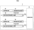
FIG. 3 is a block diagram illustrating a configuration of the vehicular lamp. -
FIG. 4A is a perspective view illustrating a first light deflector. -
FIG. 4B is a perspective view illustrating a second light deflector. -
FIGS. 5A and 5B are views to describe an operation of a piezoelectric actuator having a meander structure. -
FIGS. 6A and 6B are schematic views illustrating first, second scanning range in a virtual vertical screen S. -
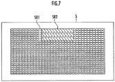
FIG. 7 is a schematic view illustrating a state where laser spots are scanned in the first, second scanning ranges on the virtual vertical screen S. -
FIG. 8 is a schematic view illustrating an irradiation range in a straight road. -
FIG. 9 is a schematic view illustrating an irradiation range in a state where a vehicle is approaching a curved part of a road. -
FIG. 10 is a schematic view illustrating a state where all inclined laser spots are scanned in a whole scanning range. - As illustrated in
FIG. 1 , avehicular lamp 2 includes aprojection lens 3, alens holder 4 that holds theprojection lens 3, abody tube 5 attached to a rear end of thelens holder 4, and abottom closure 6 that closes an opening on a rear side of thebody tube 5. In the present embodiment, thevehicular lamp 2 is used as a headlight of a vehicle, for example. - As illustrated in
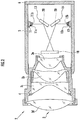
FIG. 2 , thevehicular lamp 2 includes first and secondexcitation light sources first light deflector 13 that scans excitation light from the firstexcitation light source 11 two-dimensionally (in a horizontal direction and in a vertical direction), and asecond light deflector 14 that scans excitation light from the secondexcitation light source 12 two-dimensionally. Driving of the first and secondexcitation light sources second light deflectors FIG. 3 ), which will be described later in detail. Note that the number of excitation light sources and light deflectors is modifiable appropriately. - Further, the
vehicular lamp 2 includes a fluorescent substance 18 (a projection body) on which a two-dimensional image corresponding to a predetermined light distribution pattern is drawn by light scanned by the first andsecond light deflectors fluorescent substance 18 is projected forward by theprojection lens 3. - The first and second the
excitation light sources second light deflectors fluorescent substance 18 are placed inside thebody tube 5 and are fixed by fixing members (not shown). Note that a fin for heat dissipation may be provided on an outer peripheral surface of thebody tube 5. - The first
excitation light source 11 includes, for example, a semiconductorlight emitting element 11a such as a laser diode (LD) that emits a laser beam in a blue range (having a luminous wavelength of 450 nm, for example) as the excitation light, and acondenser lens 11b that condenses (collimates, for example) light from the semiconductorlight emitting element 11 a. - Similarly to the first
excitation light source 11, the secondexcitation light source 12 includes a semiconductorlight emitting element 12a and acondenser lens 12b. Note that the semiconductorlight emitting elements light emitting elements light emitting elements - The first
excitation light source 11 and the secondexcitation light source 12 emit respective laser beams toward rotation centers of respectivelight deflection mirrors 20 of the first andsecond light deflectors - The
fluorescent substance 18 receives laser beams two-dimensionally scanned by the first andsecond light deflectors fluorescent substance 18 is placed in the vicinity of a focus of theprojection lens 3. Note that, inFIG. 2 , a thickness of thefluorescent substance 18 is illustrated in an exaggerated manner. - For example, in a case where a laser diode (LD) that emits a laser beam in a blue region is used as the semiconductor
light emitting elements excitation light sources fluorescent substance 18. A two-dimensional image corresponding to a predetermined light distribution pattern is drawn on thefluorescent substance 18 as a white image by the laser beam in the blue region two-dimensionally scanned by thefirst light deflector 13. The reason why the two-dimensional image is drawn as the white image is as follows. That is, in the case where the laser beam in the blue region is applied, thefluorescent substance 18 emits white light (pseudo white light) due to color mixture between the laser beam in the blue region, passing through thefluorescent substance 18, and light (yellow light) emitted due to the laser beam in the blue region. - In the meantime, in a case where a laser diode (LD) that emits a laser beam in a near-ultraviolet region is used as the semiconductor
light emitting elements fluorescent substance 18. A two-dimensional image corresponding to a predetermined light distribution pattern is drawn on thefluorescent substance 18 as a white image by the laser beam in the near-ultraviolet region two-dimensionally scanned by the firstlight deflector 13. The reason why the two-dimensional image is drawn as the white image is as follows. That is, in a case where the laser beam in the near-ultraviolet region is applied, thefluorescent substance 18 emits white light (pseudo white light) due to color mixture of light (light of three colors of red, green, and blue) emitted due to the laser beam in the near-ultraviolet region. Note that white light may be emitted by exciting a blue fluorescent substance and a yellow fluorescent substance by a near-ultraviolet laser beam. - The
projection lens 3 is constituted by four lenses 3a to 3d, and each of the lenses 3a to 3d is held in thelens holder 4. Aberration (field curvature) of each of the lenses 3a to 3d is corrected so that an image surface becomes a flat surface, and chromatic aberration thereof is also corrected. In this case, a flat shape substance is used as thefluorescent substance 18 so as to be placed along an image surface (a flat surface). - A focus of the
projection lens 3 is positioned in the vicinity of thefluorescent substance 18. Due to theprojection lens 3, it is possible to remove an influence of aberration with respect to the predetermined light distribution pattern as compared with a case where one convex lens is used. Further, since thefluorescent substance 18 has a flat shape, it is possible to easily manufacture thefluorescent substance 18 as compared with a case where thefluorescent substance 18 has a curved shape. Further, since thefluorescent substance 18 has a flat shape, it is possible to easily draw a two-dimensional image as compared with a case where thefluorescent substance 18 has a curved shape. - Note that, the
projection lens 3 may be formed as a projection lens constituted by one aspherical lens in which aberration (field curvature) is not corrected so that an image surface becomes a flat surface. In this case, a substance having a curved shape corresponding to the field curvature is used as thefluorescent substance 18 and is placed along the field curvature. - The
projection lens 3 projects forward the two-dimensional image drawn on thefluorescent substance 18, so as to form a low-beam distribution pattern, for example, as the predetermined light distribution pattern, on a virtual vertical screen S (placed at a position about 25 m forward from the vehicular lamp 2) directly facing to thevehicular lamp 2. - The first and second
light deflectors condenser lenses excitation light sources - Due to the laser beam emitted from the first
excitation light source 11, an elliptical laser spot is formed on the virtual vertical screen S. The firstexcitation light source 11 is placed so that a longitudinal direction of the elliptical laser spot is lateral (parallel to the horizontal direction) (seeFIG. 6A ). Note that the laser beam may be emitted so that the longitudinal direction of the elliptical shape of the laser spot is vertical (parallel to the vertical direction). - Due to the laser beam emitted from the second
excitation light source 12, an elliptical laser spot is formed on the virtual vertical screen S. The secondexcitation light source 12 is placed so that a longitudinal direction of the elliptical laser spot is inclined relative to the horizontal direction and the vertical direction (seeFIG. 6B ). In the present embodiment, a longitudinal direction of the elliptical shape of the laser spot from the secondexcitation light source 12 is inclined at 45° relative to the horizontal direction. The inclination angle is modifiable appropriately, and it is preferable that the inclination angle be set so as to correspond to an angle of a cut-off line determined in the laws and regulations, which is around 15° to 45°. - As illustrated in
FIG. 3 , the first and secondexcitation light sources light deflectors control device 16 that controls thevehicular lamp 2 generally, so that driving thereof is controlled by thecontrol device 16. - The first and second
light deflectors - As illustrated in
FIG. 4A , the firstlight deflector 13 is a biaxial light deflector and is manufactured by use of a semiconductor process and an MEMS (Micro Electro Mechanical Systems) technique. The firstlight deflector 13 reflects light incident thereon from a given direction by thelight deflection mirror 20 serving as a micromirror that rotates, so as to emit the light as reflection light (a laser beam). - The first
light deflector 13 includes afirst support portion 21, and thefirst support portion 21 is constituted by thelight deflection mirror 20, semi-annularpiezoelectric actuators torsion bars excitation light source 11 is reflected by thelight deflection mirror 20, so as to perform scanning on the virtual vertical screen S with reflection light (the laser beam) via thefluorescent substance 18 and theprojection lens 3. - At this time, the
control device 16 transmits a control signal to the firstlight deflector 13 and the firstexcitation light source 11. Due to the control signal, the semi-annularpiezoelectric actuators light deflector 13 are driven, so that thetorsion bars piezoelectric actuators light deflection mirror 20. Further, due to the control signal, ON/OFF and luminance of the laser beam are controlled in the first and secondexcitation light sources - In the present embodiment, in a biaxial rectangular coordinate system, a horizontal rotating axis passing through a center of the circular
light deflection mirror 20 is defined as an X-axis, and a vertical rotating axis is defined as a Y-axis. Further, inFIG. 4 , the X-axis is assumed the right-left direction, the Y-axis is assumed an up-down direction, and a thickness direction of thelight deflection mirror 20 is assumed a front-rear direction. - The first
light deflector 13 includes a rectangular annularsecond support portion 22, and afirst support portion 21 is disposed in a center of thesecond support portion 22. Further, bellows-shapedpiezoelectric actuators first support portion 21, and are connected to a side lower end of thefirst support portion 21 and thesecond support portion 22. Note that, inFIG. 3 , the first and second thesupport portions piezoelectric actuators - The
piezoelectric actuators piezoelectric actuators first support portion 21 reciprocatingly rotates around the horizontal direction, that is, the X-axis passing through the center of thelight deflection mirror 20 in the figure. - Further, as described above, when the semi-annular
piezoelectric actuators light deflection mirror 20 accords with axes of thetorsion bars light deflection mirror 20 in the figure. - As a result, at the time when the laser beam is reflected by the
light deflection mirror 20, the firstlight deflector 13 emits forward relative to the firstlight deflector 13, so as to perform scanning further in two directions of an X-axis direction and a Y-axis direction. - Below the
second support portion 22,electrode pads 32a to 32e (hereinafter referred to as the electrode pad 32) andelectrode pads 33a to 33e (hereinafter referred to as the electrode pad 33) are disposed. Theelectrode pads piezoelectric actuators piezoelectric actuators - Note that the first
light deflector 13 can function as a light deflector without parts corresponding to thepiezoelectric actuators first support portion 21 serves as a support, and thelight deflection mirror 20 constitutes a single-axis light deflector that reciprocatingly rotates around the Y-axis. -
FIG. 4B is a view illustrating a secondlight deflector 14. The secondlight deflector 14 has a configuration similar to the firstlight deflector 13, so detailed descriptions thereof are omitted herein. InFIG. 4A and FIG. 4B , elliptical dotted lines of respective light deflection mirrors 20 indicate respective laser spots output from the first and secondexcitation light sources light deflector 14 is different from the firstlight deflector 13 only in an orientation of the laser spot in thelight deflection mirror 20. In the firstlight deflector 13, a longitudinal direction of the laser spot is along the X-axis, whereas in the secondlight deflector 14, a longitudinal direction of the laser spot is inclined relative to the X-axis and the Y-axis. - Referring now to
FIG. 5 , an operation is described by taking thepiezoelectric actuator 31a as an example. As described above, when the firstlight deflector 13 operates thepiezoelectric actuators light deflection mirror 20 can reciprocatingly rotate around the X-axis. -
FIG. 5A is a view in which thepiezoelectric actuator 31a disposed on a left side is taken out when the firstlight deflector 13 is viewed from a front side. Thepiezoelectric actuator 31a has a shape in which four piezoelectric cantilevers are arranged side by side, and the four piezoelectric cantilevers arepiezoelectric cantilevers 31a(1), 31a(2), 31a(3), and 31a(4) sequentially from a side distanced from thefirst support portion 21. - For example, in the
piezoelectric actuator 31a, a first voltage is applied to the odd-numberedpiezoelectric cantilevers 31a(1), 31a(3). Further, a second voltage, which has a phase opposite to the first voltage, is applied to the even-numberedpiezoelectric cantilevers 31a(2), 31a(4). - As illustrated in
FIG. 5B , by applying the voltages as such, the odd-numberedpiezoelectric cantilevers 31a(1), 31a(3) can be bent and displaced in an upper direction inFIG. 5B , and the even-numberedpiezoelectric cantilevers 31a(2), 31a(4) can be bent and displaced in a lower direction inFIG. 5B . - The
piezoelectric actuator 31b is constituted by four piezoelectric cantilevers similarly to thepiezoelectric actuator 31a, and the four piezoelectric cantilevers are first, second, third, and fourth piezoelectric cantilevers sequentially from a side closer to thefirst support portion 21. Thepiezoelectric actuator 31b can bend and displace two odd-numbered piezoelectric cantilevers toward a rear side inFIG. 4 , and also bend and displace two even-numbered piezoelectric cantilevers toward a front side inFIG. 4 . - Hereby, the
light deflection mirror 20 can be displaced such that a lower side (a torsion-bar-24b side) of thelight deflection mirror 20 inFIG. 4 is placed on the front side inFIG. 4 relative to an upper side (a torsion-bar-24a side) of thelight deflection mirror 20 inFIG. 4 (the upper side is moved in a U-direction inFIG. 5 ). - Further, when the second voltage is applied to the odd-numbered
piezoelectric cantilevers 31a(1), 31a(3) and the first voltage is applied to the even-numberedpiezoelectric cantilevers 31a(2), 31a(4), thelight deflection mirror 20 can be displaced such that the upper side (the torsion-bar-24a side) of thelight deflection mirror 20 inFIG. 4 is placed on the front side inFIG. 4 relative to the lower side (the torsion-bar-24b side) of thelight deflection mirror 20 inFIG. 4 . By performing these controls successively, thelight deflection mirror 20 can be rotated (swung) around the X-axis. - As an application method of the first voltage and the second voltage, there is such a method for applying an opposite-phase voltage that changes in a sine curve or a comb-like shape to the odd-numbered piezoelectric cantilevers and the even-numbered piezoelectric cantilevers. Further, not only in the case where the cantilevers are bent alternately in the up-down direction, a state where the bending is performed in either of the upper direction and the lower direction and a state where the bending is not performed may be repeated alternately.
- In a case where the driving
vehicular lamp 2 is driven to form a low-beam distribution pattern on the virtual vertical screen S, thecontrol device 16 first transmits a control signal to the first and secondexcitation light sources light deflectors - Due to the control signal, the first and second
excitation light sources light deflectors - As illustrated in
FIG. 2 , the laser beam output from the firstexcitation light source 11 is incident on a rotation center of thelight deflection mirror 20 of the firstlight deflector 13 and scanned in the horizontal direction and in the vertical direction by thelight deflection mirror 20 that rotates. - The laser beam output from the second
excitation light source 12 is incident on a rotation center of thelight deflection mirror 20 of the secondlight deflector 14 and scanned in the horizontal direction and in the vertical direction by thelight deflection mirror 20 that rotates. - As illustrated in
FIG. 6A , the laser beam emitted from the firstexcitation light source 11 is scanned within a first scanning range SR1 on the virtual vertical screen S via the firstlight deflector 13, thefluorescent substance 18, and the projection lens 3 (a two-dimensional image is projected). In the first scanning range SR1, a central upper part is a masked region that is not irradiated with light. In order to form the masked region, thecontrol device 16 controls the firstexcitation light source 11 not to emit light when the masked region is scanned. The control signal also includes information about the masked region, and when the firstexcitation light source 11 is driven by the control signal, the laser beam emitted from the firstexcitation light source 11 is scanned in the first scanning range SR1. - As illustrated in
FIG. 6B , the laser beam emitted from the secondexcitation light source 12 is scanned within a second scanning range SR2 in the central upper part of the virtual vertical screen S via the secondlight deflector 14, thefluorescent substance 18, and theprojection lens 3. Note that the first scanning range SR1 and the second scanning range SR2 are modifiable appropriately. Further, inFIGS. 6 to 9 , a size of the laser spot is illustrated in an exaggerated manner. - As illustrated in
FIG. 7 , light obtained by combining the laser beam scanned by the firstlight deflector 13 in the first scanning range SR1 with the laser beam scanned by the secondlight deflector 14 in the second scanning range SR2 can be emitted from thevehicular lamp 2. - In a case where the
vehicular lamp 2 is provided on a vehicle and driven, thecontrol device 16 acquires road information based on a camera (not shown) provided in the vehicle, a handle operation amount of the vehicle, and the like, so as to determine whether or not the vehicle is approaching a curve based on the road information thus acquired. - In a case where it is determined that the vehicle has not been approached the curve (it is determined that the vehicle travels on a straight road), the
control device 16 controls driving of the first and secondexcitation light sources FIG. 8 . - The
control device 16 masks a part of the first scanning range SR1 and a part of the second scanning range SR2. Due to the masking process, a cut-offline (a boundary line between an irradiation region and a masked region) inclined relative to the horizontal direction and the vertical direction is formed in the second scanning range SR2. Note that, inFIGS. 8 and9 , a part where the laser spots are not drawn is the masked region. Further,FIGS. 8 and9 illustrate an irradiation range at the time of low-beam irradiation. - In comparison with a case where the masking process is performed along the inclined cut-off line with respect to the laser beam emitted from the first
excitation light source 11 and having lateral laser spots, the second scanning range SR2 is scanned with the laser beam with laser spots having a longitudinal direction in a direction along the inclined cut-offline, thereby making it possible to show the cut-offline more clearly. - Further, the irradiation region that forms a boundary line with respect to a bottom end of the masked region is formed by the laser beam (the laser beam from the first excitation light source 11) having the lateral laser spots. Accordingly, an end line of the irradiation region is a fine straight line. Note that the inclined cut-off line may be formed by masking a predetermined part of the first scanning range SR1 and a predetermined part of the second scanning range SR2 without acquiring the road information.
- In a case where it is determined that the vehicle is approaching a curve based on the road information, the
control device 16 controls driving of the first and secondexcitation light sources FIG. 9 . - The
control device 16 controls the driving so that the cut-off line shifts to the right side in the second scanning range SR2 as compared with traveling on the straight road. This is a control performed in the case where the vehicle is approaching a curve toward the right side, and in the case where the vehicle is approaching a curve toward the left side, thecontrol device 16 shifts the cut-off line to the left side in the second scanning range SR2 as compared with the traveling on the straight road. - Note that, as illustrated in
FIG. 10 , all the scanning range may be scanned by the laser beam output from the secondexcitation light source 12. In this case, the firstexcitation light source 11 and the firstlight deflector 13 are not required. In this embodiment, by performing the masking process similar to the above embodiment, it is possible to easily form a cut-off line inclined relative to the horizontal direction and the vertical direction in all the scanning range. - Note that the above embodiment uses the excitation light source, but may use a light source that emits a color of the light source as it is. In this case, the fluorescent substance (the projection body) is not required, and the light from the light source is projected just as it is. Further, instead of the fluorescent substance, a diffused plate having a light-transmitting property may be used. Further, the light source should emit one collected ray of light, and the light may be guided by fibers, for example. The light guided to the fibers may be also white light obtained by mixing RGB.
- Further, the above embodiment uses a rectangular fluorescent substance, but is not limited to this, and the fluorescent substance may be elliptical.
Claims (4)
- A vehicular lamp forming a predetermined light distribution pattern, the vehicular lamp characterized by comprising:a first light source provided to emit light forming an elliptical spot such that a longitudinal direction of the elliptical spot is inclined to a horizontal direction and a vertical direction;a first light deflector configured to scan the light emitted from the first light source; anda light system configured to form the predetermined light distribution pattern by the light scanned by the first light deflector.
- The vehicular lamp according to claim 1, characterized by comprising:a second light source provided to emit light forming an elliptical spot such that a longitudinal direction of the elliptical spot is parallel to the horizontal direction or the vertical direction; anda second light deflector configured to scan the light emitted from the second light source, whereinthe light system forms the predetermined light distribution pattern by the light scanned by the first light deflector and the light scanned by the second light deflector.
- The vehicular lamp according to claim 2, characterized in that
the light emitted from the second light source is configured such that the longitudinal direction of the elliptical spot is parallel to the horizontal direction. - The vehicular lamp according to any one of claims 1 to 3, characterized by comprising:a control unit configured to control driving of the first light source, wherein:the first light source emits light so that a low beam is emitted from the vehicle;the control unit controls driving of the first light source so as to form an irradiation region and a masked region where the light is turned off by a mask in a case where the light is emitted, and also the control unit sets a boundary line between the irradiation region and the masked region based on information obtained externally.
Applications Claiming Priority (1)
| Application Number | Priority Date | Filing Date | Title |
|---|---|---|---|
| JP2016011547A JP2017134908A (en) | 2016-01-25 | 2016-01-25 | Vehicle lighting |
Publications (1)
| Publication Number | Publication Date |
|---|---|
| EP3196545A1 true EP3196545A1 (en) | 2017-07-26 |
Family
ID=57860720
Family Applications (1)
| Application Number | Title | Priority Date | Filing Date |
|---|---|---|---|
| EP17152163.6A Withdrawn EP3196545A1 (en) | 2016-01-25 | 2017-01-19 | Vehicular lamp |
Country Status (2)
| Country | Link |
|---|---|
| EP (1) | EP3196545A1 (en) |
| JP (1) | JP2017134908A (en) |
Cited By (1)
| Publication number | Priority date | Publication date | Assignee | Title |
|---|---|---|---|---|
| CN111288408A (en) * | 2018-12-06 | 2020-06-16 | 丰田自动车株式会社 | Vehicle headlamp |
Families Citing this family (2)
| Publication number | Priority date | Publication date | Assignee | Title |
|---|---|---|---|---|
| JP6571734B2 (en) | 2017-09-04 | 2019-09-04 | トヨタ自動車株式会社 | Vehicle lighting device |
| JPWO2019230664A1 (en) * | 2018-05-31 | 2021-06-24 | 株式会社小糸製作所 | Vehicle lighting |
Citations (6)
| Publication number | Priority date | Publication date | Assignee | Title |
|---|---|---|---|---|
| US20090046474A1 (en) * | 2007-08-13 | 2009-02-19 | Koito Manufacturing Co., Ltd. | Vehicular headlamp |
| JP2010036835A (en) * | 2008-08-08 | 2010-02-18 | Koito Mfg Co Ltd | Vehicle lighting unit |
| DE102012205438A1 (en) * | 2012-04-03 | 2013-10-10 | Bayerische Motoren Werke Aktiengesellschaft | Lighting device for a motor vehicle |
| JP2014017094A (en) | 2012-07-06 | 2014-01-30 | Sharp Corp | Lighting system and vehicular head lamp |
| JP2014089990A (en) * | 2014-02-20 | 2014-05-15 | Koito Mfg Co Ltd | Headlight for vehicle |
| US20150176809A1 (en) * | 2013-12-19 | 2015-06-25 | Osram Gmbh | Lighting device with phosphor surface |
-
2016
- 2016-01-25 JP JP2016011547A patent/JP2017134908A/en active Pending
-
2017
- 2017-01-19 EP EP17152163.6A patent/EP3196545A1/en not_active Withdrawn
Patent Citations (6)
| Publication number | Priority date | Publication date | Assignee | Title |
|---|---|---|---|---|
| US20090046474A1 (en) * | 2007-08-13 | 2009-02-19 | Koito Manufacturing Co., Ltd. | Vehicular headlamp |
| JP2010036835A (en) * | 2008-08-08 | 2010-02-18 | Koito Mfg Co Ltd | Vehicle lighting unit |
| DE102012205438A1 (en) * | 2012-04-03 | 2013-10-10 | Bayerische Motoren Werke Aktiengesellschaft | Lighting device for a motor vehicle |
| JP2014017094A (en) | 2012-07-06 | 2014-01-30 | Sharp Corp | Lighting system and vehicular head lamp |
| US20150176809A1 (en) * | 2013-12-19 | 2015-06-25 | Osram Gmbh | Lighting device with phosphor surface |
| JP2014089990A (en) * | 2014-02-20 | 2014-05-15 | Koito Mfg Co Ltd | Headlight for vehicle |
Cited By (2)
| Publication number | Priority date | Publication date | Assignee | Title |
|---|---|---|---|---|
| CN111288408A (en) * | 2018-12-06 | 2020-06-16 | 丰田自动车株式会社 | Vehicle headlamp |
| CN111288408B (en) * | 2018-12-06 | 2022-10-14 | 丰田自动车株式会社 | Vehicle headlamp |
Also Published As
| Publication number | Publication date |
|---|---|
| JP2017134908A (en) | 2017-08-03 |
Similar Documents
| Publication | Publication Date | Title |
|---|---|---|
| US10023104B2 (en) | Vehicle lighting device | |
| JP6455710B2 (en) | Vehicle lighting | |
| JP6270033B2 (en) | Vehicle lighting | |
| US20150176778A1 (en) | Lighting device | |
| JP6356454B2 (en) | Optical scanner and vehicle headlamp device | |
| EP3096074B1 (en) | Vehicle lighting fixture | |
| EP3048361B1 (en) | Vehicle lighting fixture | |
| JP6492966B2 (en) | Light source unit and image display device | |
| US20180156414A1 (en) | Vehicle lighting apparatus | |
| EP3181996A1 (en) | Vehicle lamp and vehicle irradiation system | |
| JP6684674B2 (en) | Vehicle lamp and driving method thereof | |
| US11137599B2 (en) | Display device and moving body carrying display device | |
| JP6946054B2 (en) | Vehicle lighting | |
| US20180374407A1 (en) | Image display device | |
| JP7023672B2 (en) | Vehicle lighting fixtures, control devices and control methods | |
| JP2017134908A (en) | Vehicle lighting | |
| JP7034736B2 (en) | Light irradiation device and vehicle lighting equipment | |
| CN111465802A (en) | headlamps for vehicles | |
| JP6745664B2 (en) | Vehicle lamp and its control method | |
| JP6613547B2 (en) | Vehicle lighting | |
| JP7048220B2 (en) | Vehicle lighting | |
| JP6684609B2 (en) | Vehicle lamp and its control method | |
| US11221121B1 (en) | Vehicular lamp | |
| JP2021184009A (en) | Image projection device | |
| JP7244008B2 (en) | vehicle lamp |
Legal Events
| Date | Code | Title | Description |
|---|---|---|---|
| PUAI | Public reference made under article 153(3) epc to a published international application that has entered the european phase |
Free format text: ORIGINAL CODE: 0009012 |
|
| AK | Designated contracting states |
Kind code of ref document: A1 Designated state(s): AL AT BE BG CH CY CZ DE DK EE ES FI FR GB GR HR HU IE IS IT LI LT LU LV MC MK MT NL NO PL PT RO RS SE SI SK SM TR |
|
| AX | Request for extension of the european patent |
Extension state: BA ME |
|
| STAA | Information on the status of an ep patent application or granted ep patent |
Free format text: STATUS: THE APPLICATION IS DEEMED TO BE WITHDRAWN |
|
| 18D | Application deemed to be withdrawn |
Effective date: 20180127 |