EP3196468A1 - Exhaust bearing seat, screw compressor and air-conditioning unit - Google Patents
Exhaust bearing seat, screw compressor and air-conditioning unit Download PDFInfo
- Publication number
- EP3196468A1 EP3196468A1 EP14902267.5A EP14902267A EP3196468A1 EP 3196468 A1 EP3196468 A1 EP 3196468A1 EP 14902267 A EP14902267 A EP 14902267A EP 3196468 A1 EP3196468 A1 EP 3196468A1
- Authority
- EP
- European Patent Office
- Prior art keywords
- exhaust
- bearing seat
- exhaust port
- opening
- inclination angle
- Prior art date
- Legal status (The legal status is an assumption and is not a legal conclusion. Google has not performed a legal analysis and makes no representation as to the accuracy of the status listed.)
- Granted
Links
Images


Classifications
-
- F—MECHANICAL ENGINEERING; LIGHTING; HEATING; WEAPONS; BLASTING
- F04—POSITIVE - DISPLACEMENT MACHINES FOR LIQUIDS; PUMPS FOR LIQUIDS OR ELASTIC FLUIDS
- F04C—ROTARY-PISTON, OR OSCILLATING-PISTON, POSITIVE-DISPLACEMENT MACHINES FOR LIQUIDS; ROTARY-PISTON, OR OSCILLATING-PISTON, POSITIVE-DISPLACEMENT PUMPS
- F04C29/00—Component parts, details or accessories of pumps or pumping installations, not provided for in groups F04C18/00 - F04C28/00
- F04C29/06—Silencing
-
- F—MECHANICAL ENGINEERING; LIGHTING; HEATING; WEAPONS; BLASTING
- F04—POSITIVE - DISPLACEMENT MACHINES FOR LIQUIDS; PUMPS FOR LIQUIDS OR ELASTIC FLUIDS
- F04C—ROTARY-PISTON, OR OSCILLATING-PISTON, POSITIVE-DISPLACEMENT MACHINES FOR LIQUIDS; ROTARY-PISTON, OR OSCILLATING-PISTON, POSITIVE-DISPLACEMENT PUMPS
- F04C19/00—Rotary-piston pumps with fluid ring or the like, specially adapted for elastic fluids
- F04C19/004—Details concerning the operating liquid, e.g. nature, separation, cooling, cleaning, control of the supply
-
- F—MECHANICAL ENGINEERING; LIGHTING; HEATING; WEAPONS; BLASTING
- F04—POSITIVE - DISPLACEMENT MACHINES FOR LIQUIDS; PUMPS FOR LIQUIDS OR ELASTIC FLUIDS
- F04C—ROTARY-PISTON, OR OSCILLATING-PISTON, POSITIVE-DISPLACEMENT MACHINES FOR LIQUIDS; ROTARY-PISTON, OR OSCILLATING-PISTON, POSITIVE-DISPLACEMENT PUMPS
- F04C18/00—Rotary-piston pumps specially adapted for elastic fluids
- F04C18/08—Rotary-piston pumps specially adapted for elastic fluids of intermeshing-engagement type, i.e. with engagement of co-operating members similar to that of toothed gearing
- F04C18/12—Rotary-piston pumps specially adapted for elastic fluids of intermeshing-engagement type, i.e. with engagement of co-operating members similar to that of toothed gearing of other than internal-axis type
- F04C18/14—Rotary-piston pumps specially adapted for elastic fluids of intermeshing-engagement type, i.e. with engagement of co-operating members similar to that of toothed gearing of other than internal-axis type with toothed rotary pistons
- F04C18/16—Rotary-piston pumps specially adapted for elastic fluids of intermeshing-engagement type, i.e. with engagement of co-operating members similar to that of toothed gearing of other than internal-axis type with toothed rotary pistons with helical teeth, e.g. chevron-shaped, screw type
-
- F—MECHANICAL ENGINEERING; LIGHTING; HEATING; WEAPONS; BLASTING
- F04—POSITIVE - DISPLACEMENT MACHINES FOR LIQUIDS; PUMPS FOR LIQUIDS OR ELASTIC FLUIDS
- F04C—ROTARY-PISTON, OR OSCILLATING-PISTON, POSITIVE-DISPLACEMENT MACHINES FOR LIQUIDS; ROTARY-PISTON, OR OSCILLATING-PISTON, POSITIVE-DISPLACEMENT PUMPS
- F04C19/00—Rotary-piston pumps with fluid ring or the like, specially adapted for elastic fluids
- F04C19/005—Details concerning the admission or discharge
-
- F—MECHANICAL ENGINEERING; LIGHTING; HEATING; WEAPONS; BLASTING
- F04—POSITIVE - DISPLACEMENT MACHINES FOR LIQUIDS; PUMPS FOR LIQUIDS OR ELASTIC FLUIDS
- F04C—ROTARY-PISTON, OR OSCILLATING-PISTON, POSITIVE-DISPLACEMENT MACHINES FOR LIQUIDS; ROTARY-PISTON, OR OSCILLATING-PISTON, POSITIVE-DISPLACEMENT PUMPS
- F04C29/00—Component parts, details or accessories of pumps or pumping installations, not provided for in groups F04C18/00 - F04C28/00
- F04C29/02—Lubrication; Lubricant separation
-
- F—MECHANICAL ENGINEERING; LIGHTING; HEATING; WEAPONS; BLASTING
- F04—POSITIVE - DISPLACEMENT MACHINES FOR LIQUIDS; PUMPS FOR LIQUIDS OR ELASTIC FLUIDS
- F04C—ROTARY-PISTON, OR OSCILLATING-PISTON, POSITIVE-DISPLACEMENT MACHINES FOR LIQUIDS; ROTARY-PISTON, OR OSCILLATING-PISTON, POSITIVE-DISPLACEMENT PUMPS
- F04C29/00—Component parts, details or accessories of pumps or pumping installations, not provided for in groups F04C18/00 - F04C28/00
- F04C29/12—Arrangements for admission or discharge of the working fluid, e.g. constructional features of the inlet or outlet
Definitions
- the present application relates to the field of compressor, and particularly to an exhaust bearing seat, a screw compressor and an air-conditioning unit.
- a semi-closed screw compressor in the case that the compressor is not provided with a built-in oil separating cartridge, that an exhaust bearing seat is surrounded by an oil separating barrel may reduce noise.
- gas generated from the compressor flows into an interior of the oil separating barrel through the exhaust bearing seat, and then is discharged from the compressor by a discharge port of the oil separating barrel.
- the compressor is not provided with the built-in oil separating cartridge, it is necessary to locate the discharge port of the oil separating barrel at a lower part such that refrigeration oil carried in the exhaust gas can be smoothly exhausted from the compressor.
- an exhaust port of the exhaust bearing seat is generally located at the lower part of the exhaust bearing seat. In this case, a distance between the exhaust port of the exhaust bearing seat and the discharge port of the oil separating barrel is too small, and the oil separating barrel cannot sufficiently isolate the noise.
- An object of the present application is to provide an exhaust bearing seat, a screw compressor and an air-conditioning unit, which facilitates reducing noise from the gas flow pulsation.
- an exhaust bearing seat is provided according to the present application.
- the exhaust bearing seat is provided with an exhaust port.
- An opening of the exhaust port is orientated in a way that, in the case that an exhaust bearing seat is sheathed in a housing, gas exhausted from the exhaust port has a component which rotationally flows along an inner wall of the housing and around an axis of the housing.
- the opening of the exhaust port is orientated to be substantially perpendicular to an axis of a male rotor bearing chamber or an axis of a female rotor bearing chamber in the exhaust bearing seat.
- the exhaust port is inclined upward to allow gas flow exhausted form the exhaust port to flow obliquely upward.
- the opening of the exhaust port includes an exhaust port upper edge and an exhaust port lower edge.
- the exhaust port upper edge is an arc, and a tangent line of the arc and a horizontal plane form an opening inclination angle ⁇ 1 greater than 0 degree
- the exhaust port lower edge is also an arc, and a tangent line of the arc and a horizontal plane form an opening inclination angle ⁇ 2 greater than 0 degree.
- an oil return hole is provided in the exhaust bearing seat at a position close to the exhaust port upper edge.
- the opening inclination angle ⁇ 1 of the exhaust port upper edge is set as large as possible, and the opening inclination angle ⁇ 2 of the exhaust port lower edge is smaller than the opening inclination angle ⁇ 1 of the exhaust port upper edge by 5 degrees to 10 degrees.
- the opening inclination angle ⁇ 1 of the exhaust port upper edge ranges from 25 degrees to 65 degrees
- the opening inclination angle ⁇ 2 of the exhaust port lower edge is smaller than the opening inclination angle ⁇ 1 of the exhaust port upper edge by 5 degrees to 10 degrees.
- the opening of the exhaust port is located at a side of the male rotor bearing chamber in the exhaust bearing seat.
- a screw compressor is further provided according to the present application.
- the screw compressor includes an oil separating barrel having a discharge port.
- the screw compressor further includes the exhaust bearing seat according to any one of above embodiments, and the exhaust bearing seat is sheathed in the oil separating barrel.
- the discharge port of the oil separating barrel is offset from the opening of the exhaust port of the exhaust bearing seat in a horizontal direction.
- the air-conditioning unit includes the screw compressor according to any one of above embodiments.
- the present application at least has the following beneficial effects.
- the exhaust port provided in the exhaust bearing seat according to the present application can guide the gas flow to rotationally flow along the inner wall of the housing and around the axis of the housing, which extends the flow path of the gas flow in the housing, and facilitates reducing the noise from the gas flow pulsation.
- the exhaust bearing seat includes a piston chamber 2, a male rotor bearing chamber 3 and a female rotor bearing chamber 4, and further includes an exhaust port 1 provided in the exhaust bearing seat.
- the exhaust port 1 is in communication with an exhaust end of the piston chamber 2.
- An opening of the exhaust port 1 is orientated in such a way that, in the case that the exhaust bearing seat is sheathed in a housing, gas exhausted from the exhaust port 1 has a component which rotationally flows along an inner wall of the housing and around an axis of the housing. In other words, at least a portion of gas flow can rotationally flow along the inner wall of the housing and around the axis of the housing.
- the above housing may be a housing for an oil separating barrel.
- the opening of the exhaust port 1 can be orientated to be strictly and absolutely perpendicular to or substantially perpendicular to an axis of the piston chamber 2, an axis of the male rotor bearing chamber 3 or an axis of the female rotor bearing chamber 4 provided in the exhaust bearing seat.
- the opening of the exhaust port 1 can be inclined upward and have a preset inclination angle, such that the gas flow exhausted through the exhaust port 1 has an obliquely upward flowing velocity.
- the exhaust port 1 is configured in such a way that the opening thereof is inclined upward and has a preset inclination angle, which enables the gas to be at a particular circumferential velocity when being exhausted from the exhaust port 1, such that the gas flow exhausted through the exhaust bearing seat can rotationally flow along an inner wall of the oil separating barrel, which extends a flow path of the gas flow inside the oil separating barrel, facilitates the reduction of noise, and also facilitates better separating the refrigerants from lubricants.
- the exhaust port 1 can be located at a side of the piston chamber 2 and the male rotor bearing chamber 3.
- a side of the female rotor bearing chamber 4 and the piston chamber 2 is generally used for arranging an oil supply passage for the piston chamber, and that the exhaust bearing seat is closer to the side of the female rotor in an overall arrangement of the exhaust bearing seat to a body of the compressor, which is determined by the fact that a male rotor drives a female rotor.
- an axial space on the side of the piston chamber 2 and the male rotor bearing chamber 3 is relatively larger, which facilitates the arrangement of the exhaust port 1.
- the exhaust port 1 has an upwardly inclined opening, and the particular inclination angle of the opening is related to a practical configuration of the compressor, and it is desired that the inclination angle is as large as possible. This is because that the gas, after flowing out of the exhaust bearing seat, needs to be deflected upward first to flow along the inner wall of the oil separating barrel, and if the flowing direction is changed in a too large degree, the flowing loss of the gas flow will be high; and the larger the upward inclination angle is, the less the flowing direction change of the gas after exhausted from the exhaust bearing seat will be, and thus the less the flowing loss will be. In addition, it is also necessary to ensure that the area of the exhaust port 1 is sufficiently large thus the velocity of flow can be effectively reduced to a certain flow rate, thereby the resistance and flowing loss can be reduced and the noise can be reduced.
- the opening of the exhaust port 1 includes an exhaust port upper edge 11 and an exhaust port lower edge 12.
- the exhaust port upper edge 11 may be an arc, and an included angle between a tangent line of the arc and a horizontal plane functions as an opening inclination angle ⁇ 1 of the exhaust port upper edge 11.
- the exhaust port lower edge 12 may also be an arc, and an included angle between a tangent line of the arc and a horizontal plane functions as an opening inclination angle ⁇ 2 of the exhaust port lower edge 12.
- a bearing seat oil return hole 13 is provided in the exhaust bearing seat at a position close to the exhaust port upper edge 11.
- the opening inclination angle ⁇ 1 of the exhaust port upper edge 11 should be set as large as possible, but should not cause the exhaust port upper edge 11 to interfere with the bearing seat oil return hole 13. Specifically, the opening inclination angle ⁇ 1 of exhaust port upper edge 11 should be set to ensure that the bearing seat oil return hole 13 has a sufficient safe wall thickness.
- the opening inclination angle ⁇ 2 of the exhaust port lower edge 12 should be smaller than the opening inclination angle ⁇ 1 of the exhaust port upper edge 11 by 5 degrees to 10 degrees, which not only allows gas flow to flow obliquely upward, but also facilitates enlarging the exhaust port area and the reducing the flow rate, thereby reducing the resistance loss and the noise.
- the opening inclination angle ⁇ 1 of the exhaust port upper edge 11 of the exhaust port 1 will directly determine the flowing direction of the gas flow when be exhausted from the exhaust bearing seat.
- the opening inclination angle ⁇ 1 of the exhaust port upper edge 11 may range from 25 degrees to 65 degrees, for example 30 degrees.
- the opening inclination angle ⁇ 2 of the exhaust port lower edge 12 should be smaller than the opening inclination angle ⁇ 1 of the exhaust port upper edge 11 by 5 degrees to 10 degrees, for example, the opening inclination angle ⁇ 2 of the exhaust port lower edge 12 may be 24 degrees.
- the axial length L of the exhaust port 1 of the exhaust bearing seat should be set as large as possible so as to achieve a low velocity of flow of the gas flow.
- the exhaust bearing seat according to the present application can be applied to a screw compressor.
- the screw compressor includes an oil separating barrel 5, a compressor body 6 and an exhaust bearing seat according to any of the above embodiments.
- the exhaust bearing seat is arranged in the oil separating barrel 5 at an exhaust end of the compressor body 6.
- the opening of the exhaust port 1 of the exhaust bearing seat can be arranged at the side of the piston chamber 2 and the male rotor bearing chamber 3, and opens towards a radial direction of the exhaust bearing seat, and opens inclined upward in a preset inclination angle.
- a discharge port 51 of the oil separating barrel 5 is arranged at the bottom of the oil separating barrel 5 at the side of the piston chamber 2 and the male rotor bearing chamber 3. The discharge port 51 of the oil separating barrel 5 is offset from the opening of the exhaust port 1 of the exhaust bearing seat in a horizontal direction.
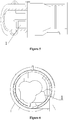
- the exhaust port 1 of the exhaust bearing seat is inclined upward so as to render a velocity to the gas flow, which enables the gas flow exhausted through the exhaust bearing seat to flow along the inner wall of the oil separating barrel 5 (as shown in Figures 5 and 6 ), and then to be discharged via the discharge port 51 of the oil separating barrel 5 after making a complete revolution.
- the flow velocity of the gas flow exhausted from the exhaust port 1 of the exhaust bearing seat is relatively high (>10m/s), and in the case that the exhaust port 1 of the exhaust bearing seat is configured to have an upward inclination angle, the gas flow may flow along the inner wall of the oil separating barrel 5 under the guiding of the exhaust port 1 of the exhaust bearing seat.
- the gas flow exhausted from the exhaust bearing seat flows at a certain velocity, and at an upward inclination angle after passing through the exhaust port 1, and further as the gas flow is sheathed in the oil separating barrel, the gas flow can rotationally flow along the inner wall of the oil separating barrel 5 and around the axis of the oil separating barrel 5.
- the exhaust port 1 of the exhaust bearing seat is located further away from the discharge port 51 of the oil separating barrel 5.
- the exhaust port 1 of the exhaust bearing seat being provided at the side may also allow the gas flow exhausted from the exhaust bearing seat to flow along the inner wall of the oil separating barrel 5 and then be discharged through the discharge port 51 of the oil separating barrel 5, which can reduce the noise caused by the gas exhausted from the exhaust port 1 of the exhaust bearing seat to a certain extent.
- the screw compressor according to the present application can be applied to an air-conditioning unit.
- the air-conditioning unit includes the screw compressor according to any one of the above embodiments.
Landscapes
- Engineering & Computer Science (AREA)
- Mechanical Engineering (AREA)
- General Engineering & Computer Science (AREA)
- Applications Or Details Of Rotary Compressors (AREA)
- Structures Of Non-Positive Displacement Pumps (AREA)
Abstract
Description
- This application claims the priority to Chinese Patent Application No.
201410484100.6 - The present application relates to the field of compressor, and particularly to an exhaust bearing seat, a screw compressor and an air-conditioning unit.
- In a semi-closed screw compressor, in the case that the compressor is not provided with a built-in oil separating cartridge, that an exhaust bearing seat is surrounded by an oil separating barrel may reduce noise. In this case, gas generated from the compressor flows into an interior of the oil separating barrel through the exhaust bearing seat, and then is discharged from the compressor by a discharge port of the oil separating barrel. As the compressor is not provided with the built-in oil separating cartridge, it is necessary to locate the discharge port of the oil separating barrel at a lower part such that refrigeration oil carried in the exhaust gas can be smoothly exhausted from the compressor. However, for a screw compressor with a slide valve structure positioned in a lower part, an exhaust port of the exhaust bearing seat is generally located at the lower part of the exhaust bearing seat. In this case, a distance between the exhaust port of the exhaust bearing seat and the discharge port of the oil separating barrel is too small, and the oil separating barrel cannot sufficiently isolate the noise.
- An object of the present application is to provide an exhaust bearing seat, a screw compressor and an air-conditioning unit, which facilitates reducing noise from the gas flow pulsation.
- To achieve the above object, an exhaust bearing seat is provided according to the present application. The exhaust bearing seat is provided with an exhaust port. An opening of the exhaust port is orientated in a way that, in the case that an exhaust bearing seat is sheathed in a housing, gas exhausted from the exhaust port has a component which rotationally flows along an inner wall of the housing and around an axis of the housing.
- In a preferred or optional embodiment, the opening of the exhaust port is orientated to be substantially perpendicular to an axis of a male rotor bearing chamber or an axis of a female rotor bearing chamber in the exhaust bearing seat.
- In a preferred or optional embodiment, the exhaust port is inclined upward to allow gas flow exhausted form the exhaust port to flow obliquely upward.
- In a preferred or optional embodiment, the opening of the exhaust port includes an exhaust port upper edge and an exhaust port lower edge. The exhaust port upper edge is an arc, and a tangent line of the arc and a horizontal plane form an opening inclination angle θ1 greater than 0 degree, the exhaust port lower edge is also an arc, and a tangent line of the arc and a horizontal plane form an opening inclination angle θ2 greater than 0 degree.
- In a preferred or optional embodiment, an oil return hole is provided in the exhaust bearing seat at a position close to the exhaust port upper edge. On the premise that the oil return hole has a safe wall thickness, the opening inclination angle θ1 of the exhaust port upper edge is set as large as possible, and the opening inclination angle θ2 of the exhaust port lower edge is smaller than the opening inclination angle θ1 of the exhaust port upper edge by 5 degrees to 10 degrees.
- In a preferred or optional embodiment, the opening inclination angle θ1 of the exhaust port upper edge ranges from 25 degrees to 65 degrees, the opening inclination angle θ2 of the exhaust port lower edge is smaller than the opening inclination angle θ1 of the exhaust port upper edge by 5 degrees to 10 degrees.
- In a preferred or optional embodiment, the opening of the exhaust port is located at a side of the male rotor bearing chamber in the exhaust bearing seat.
- To achieve the above object, a screw compressor is further provided according to the present application. The screw compressor includes an oil separating barrel having a discharge port. The screw compressor further includes the exhaust bearing seat according to any one of above embodiments, and the exhaust bearing seat is sheathed in the oil separating barrel.
- In a preferred or optional embodiment, the discharge port of the oil separating barrel is offset from the opening of the exhaust port of the exhaust bearing seat in a horizontal direction.
- To achieve the above object, an air-conditioning unit is further provided according to the present application. The air-conditioning unit includes the screw compressor according to any one of above embodiments.
- Based on the above technical solutions, the present application at least has the following beneficial effects.
- The exhaust port provided in the exhaust bearing seat according to the present application can guide the gas flow to rotationally flow along the inner wall of the housing and around the axis of the housing, which extends the flow path of the gas flow in the housing, and facilitates reducing the noise from the gas flow pulsation.
- The drawings described here are intended to facilitate a further understanding to the present application, and constitute a part of the present application. The exemplary embodiments of the present application and the description thereof are used to explain the present application, and are not intended to unduly limit the present application. In the drawings:
-
Figure 1 is a schematic perspective view showing the structure of an exhaust bearing seat according to the present application; -
Figure 2 is a schematic sectional view of the exhaust bearing seat according to the present application; -
Figure 3 is a schematic front view of the exhaust bearing seat according to the present application; -
Figure 4 is a schematic external view showing the structure of a screw compressor according to the present application; -
Figure 5 is a schematic sectional view of the screw compressor according to the present application taken along an axial direction; and -
Figure 6 is a schematic sectional view of the screw compressor according to the present application taken along a radial direction. - The technical solutions of embodiments of the present application will be clearly and completely described hereinafter in conjunction with the drawings of the embodiments of the present application. Apparently, the embodiments described below are only some examples of the present application, and not all implementations. Other embodiments obtained by those skilled in the art based on the embodiments of the present application without any creative efforts all fall into the scope of the present application.
- In the description of the present application, it is to be understood that the orientation or positional relationships indicated by terms "center", "longitudinal", "lateral", "front", "rear", "left", "right", "vertical", "horizontal", "top", "bottom", "inner", "outer" and the like are based on the orientation or positional relationships shown in the drawings, which are merely for the convenience of describing the present application and the simplification of the description, and do not indicate or imply that the device or element referred to must be in a particular orientation, or be constructed and operated in a particular orientation. Therefore the terms should not be construed as limiting the scope of the present application.
- Reference is made to
Figure 1 , which is a schematic perspective view showing the structure of an exemplary embodiment of an exhaust bearing seat according to the present application. In the exemplary embodiment, the exhaust bearing seat includes apiston chamber 2, a malerotor bearing chamber 3 and a femalerotor bearing chamber 4, and further includes anexhaust port 1 provided in the exhaust bearing seat. Theexhaust port 1 is in communication with an exhaust end of thepiston chamber 2. An opening of theexhaust port 1 is orientated in such a way that, in the case that the exhaust bearing seat is sheathed in a housing, gas exhausted from theexhaust port 1 has a component which rotationally flows along an inner wall of the housing and around an axis of the housing. In other words, at least a portion of gas flow can rotationally flow along the inner wall of the housing and around the axis of the housing. The above housing may be a housing for an oil separating barrel. - In an exemplary embodiment of the exhaust bearing seat provided according to the present application, the opening of the
exhaust port 1 can be orientated to be strictly and absolutely perpendicular to or substantially perpendicular to an axis of thepiston chamber 2, an axis of the malerotor bearing chamber 3 or an axis of the femalerotor bearing chamber 4 provided in the exhaust bearing seat. The opening of theexhaust port 1 can be inclined upward and have a preset inclination angle, such that the gas flow exhausted through theexhaust port 1 has an obliquely upward flowing velocity. - In the exhaust bearing seat according to the present application, the
exhaust port 1 is configured in such a way that the opening thereof is inclined upward and has a preset inclination angle, which enables the gas to be at a particular circumferential velocity when being exhausted from theexhaust port 1, such that the gas flow exhausted through the exhaust bearing seat can rotationally flow along an inner wall of the oil separating barrel, which extends a flow path of the gas flow inside the oil separating barrel, facilitates the reduction of noise, and also facilitates better separating the refrigerants from lubricants. - In an exemplary embodiment of the exhaust bearing seat according to the present application, the
exhaust port 1 can be located at a side of thepiston chamber 2 and the malerotor bearing chamber 3. This is in view of the fact that a side of the femalerotor bearing chamber 4 and thepiston chamber 2 is generally used for arranging an oil supply passage for the piston chamber, and that the exhaust bearing seat is closer to the side of the female rotor in an overall arrangement of the exhaust bearing seat to a body of the compressor, which is determined by the fact that a male rotor drives a female rotor. Accordingly, an axial space on the side of thepiston chamber 2 and the malerotor bearing chamber 3 is relatively larger, which facilitates the arrangement of theexhaust port 1. - In an exemplary embodiment of an exhaust bearing seat according to the present application, the
exhaust port 1 has an upwardly inclined opening, and the particular inclination angle of the opening is related to a practical configuration of the compressor, and it is desired that the inclination angle is as large as possible. This is because that the gas, after flowing out of the exhaust bearing seat, needs to be deflected upward first to flow along the inner wall of the oil separating barrel, and if the flowing direction is changed in a too large degree, the flowing loss of the gas flow will be high; and the larger the upward inclination angle is, the less the flowing direction change of the gas after exhausted from the exhaust bearing seat will be, and thus the less the flowing loss will be. In addition, it is also necessary to ensure that the area of theexhaust port 1 is sufficiently large thus the velocity of flow can be effectively reduced to a certain flow rate, thereby the resistance and flowing loss can be reduced and the noise can be reduced. - As shown in
Figure 2 , in an exemplary embodiment of the exhaust bearing seat according to the present application, the opening of theexhaust port 1 includes an exhaust portupper edge 11 and an exhaust portlower edge 12. The exhaust portupper edge 11 may be an arc, and an included angle between a tangent line of the arc and a horizontal plane functions as an opening inclination angle θ1 of the exhaust portupper edge 11. The exhaust portlower edge 12 may also be an arc, and an included angle between a tangent line of the arc and a horizontal plane functions as an opening inclination angle θ2 of the exhaust portlower edge 12. A bearing seatoil return hole 13 is provided in the exhaust bearing seat at a position close to the exhaust portupper edge 11. - In order to allow the gas flow to flow sufficiently along a surface of the inner wall of the oil separating barrel, the opening inclination angle θ1 of the exhaust port
upper edge 11 should be set as large as possible, but should not cause the exhaust portupper edge 11 to interfere with the bearing seatoil return hole 13. Specifically, the opening inclination angle θ1 of exhaust portupper edge 11 should be set to ensure that the bearing seatoil return hole 13 has a sufficient safe wall thickness. The opening inclination angle θ2 of the exhaust portlower edge 12 should be smaller than the opening inclination angle θ1 of the exhaust portupper edge 11 by 5 degrees to 10 degrees, which not only allows gas flow to flow obliquely upward, but also facilitates enlarging the exhaust port area and the reducing the flow rate, thereby reducing the resistance loss and the noise. - As the gas flow exhausted from the
exhaust port 1 will flow upward along the inner wall of the oil separating barrel, the opening inclination angle θ1 of the exhaust portupper edge 11 of theexhaust port 1 will directly determine the flowing direction of the gas flow when be exhausted from the exhaust bearing seat. The opening inclination angle θ1 of the exhaust portupper edge 11 may range from 25 degrees to 65 degrees, for example 30 degrees. The opening inclination angle θ2 of the exhaust portlower edge 12 should be smaller than the opening inclination angle θ1 of the exhaust portupper edge 11 by 5 degrees to 10 degrees, for example, the opening inclination angle θ2 of the exhaust portlower edge 12 may be 24 degrees. - As shown in
Figure 3 , in the exemplary embodiment of the exhaust bearing seat according to the present application, as long as theexhaust port 1 of the exhaust bearing seat is not overlapped with a discharge port of the oil separating barrel, the axial length L of theexhaust port 1 of the exhaust bearing seat should be set as large as possible so as to achieve a low velocity of flow of the gas flow. - The exhaust bearing seat according to the present application can be applied to a screw compressor.
- As shown in
Figure 4 , in an exemplary embodiment of a screw compressor according to the present application, the screw compressor includes anoil separating barrel 5, acompressor body 6 and an exhaust bearing seat according to any of the above embodiments. The exhaust bearing seat is arranged in theoil separating barrel 5 at an exhaust end of thecompressor body 6. - The opening of the
exhaust port 1 of the exhaust bearing seat can be arranged at the side of thepiston chamber 2 and the malerotor bearing chamber 3, and opens towards a radial direction of the exhaust bearing seat, and opens inclined upward in a preset inclination angle. Adischarge port 51 of theoil separating barrel 5 is arranged at the bottom of theoil separating barrel 5 at the side of thepiston chamber 2 and the malerotor bearing chamber 3. Thedischarge port 51 of theoil separating barrel 5 is offset from the opening of theexhaust port 1 of the exhaust bearing seat in a horizontal direction. Theexhaust port 1 of the exhaust bearing seat is inclined upward so as to render a velocity to the gas flow, which enables the gas flow exhausted through the exhaust bearing seat to flow along the inner wall of the oil separating barrel 5 (as shown inFigures 5 and 6 ), and then to be discharged via thedischarge port 51 of theoil separating barrel 5 after making a complete revolution. - Generally, the flow velocity of the gas flow exhausted from the
exhaust port 1 of the exhaust bearing seat is relatively high (>10m/s), and in the case that theexhaust port 1 of the exhaust bearing seat is configured to have an upward inclination angle, the gas flow may flow along the inner wall of theoil separating barrel 5 under the guiding of theexhaust port 1 of the exhaust bearing seat. - As the gas flow exhausted from the exhaust bearing seat flows at a certain velocity, and at an upward inclination angle after passing through the
exhaust port 1, and further as the gas flow is sheathed in the oil separating barrel, the gas flow can rotationally flow along the inner wall of theoil separating barrel 5 and around the axis of theoil separating barrel 5. - Compared with the conventional technology, in the screw compressor according to the present application, the
exhaust port 1 of the exhaust bearing seat is located further away from thedischarge port 51 of theoil separating barrel 5. In addition, theexhaust port 1 of the exhaust bearing seat being provided at the side may also allow the gas flow exhausted from the exhaust bearing seat to flow along the inner wall of theoil separating barrel 5 and then be discharged through thedischarge port 51 of theoil separating barrel 5, which can reduce the noise caused by the gas exhausted from theexhaust port 1 of the exhaust bearing seat to a certain extent. - The screw compressor according to the present application can be applied to an air-conditioning unit.
- In an exemplary embodiment of the air conditioning unit according to the present application, the air-conditioning unit includes the screw compressor according to any one of the above embodiments.
- Finally, it should be noted that, the above embodiments are only intended for describing the technical solutions of the present application and should not be interpreted as limitation to the technical solutions of the present application. Although the present application is described in detail in conjunction with the above preferred embodiments, it should be understood by the person skilled in the art that, modifications may still be made to the embodiments of the present application or equivalent substitutions may still be made to part of the technical features of the present application; and any technical solutions and improvements thereof without departing from the spirit and scope of the present application should fall into the scope of the technical solution of the present application defined by the claims.
Claims (10)
- An exhaust bearing seat, wherein the exhaust bearing seat is provided with an exhaust port, and an opening of the exhaust port is orientated in a way that, in the case that the exhaust bearing seat is sheathed in a housing, gas exhausted from the exhaust port has a component which rotationally flows along an inner wall of the housing and around an axis of the housing.
- The exhaust bearing seat according to claim 1, wherein the opening of the exhaust port is orientated to be substantially perpendicular to an axis of a male rotor bearing chamber or an axis of a female rotor bearing chamber in the exhaust bearing seat.
- The exhaust bearing seat according to claim 1 or 2, wherein the exhaust port is inclined upward to allow gas flow exhausted through the exhaust port to flow obliquely upward.
- The exhaust bearing seat according to claim 1, wherein the opening of the exhaust port comprises an exhaust port upper edge and an exhaust port lower edge, the exhaust port upper edge is an arc, and a tangent line of the arc and a horizontal plane form an opening inclination angle θ1 greater than 0 degree, the exhaust port lower edge is also an arc, and a tangent line of the arc and a horizontal plane form an opening inclination angle θ2 greater than 0 degree.
- The exhaust bearing seat according to claim 4, wherein an oil return hole is provided in the exhaust bearing seat at a position close to the exhaust port upper edge, and on the premise that the oil return hole has a safe wall thickness, the opening inclination angle θ1 of the exhaust port upper edge is set as large as possible, and the opening inclination angle θ2 of the exhaust port lower edge is smaller than the opening inclination angle θ1 of the exhaust port upper edge by 5 degrees to 10 degrees.
- The exhaust bearing seat according to claim 4 or 5, wherein the opening inclination angle θ1 of the exhaust port upper edge ranges from 25 degrees to 65 degrees, the opening inclination angle θ2 of the exhaust port lower edge is smaller than the opening inclination angle θ1 of the exhaust port upper edge by 5 degrees to 10 degrees.
- The exhaust bearing seat according to claim 1, wherein the opening of the exhaust port is positioned at the side of the male rotor bearing chamber in the exhaust bearing seat.
- A screw compressor, comprising an oil separating barrel provided with a discharge port, wherein the screw compressor further comprises the exhaust bearing seat according to any one of claims 1 to 7, and the exhaust bearing seat is sheathed in the oil separating barrel.
- The screw compressor according to claim 8, wherein the discharge port of the oil separating barrel is offset from the opening of the exhaust port of the exhaust bearing seat in a horizontal direction.
- An air-conditioning unit, comprising the screw compressor according to claim 8 or 9.
Applications Claiming Priority (2)
| Application Number | Priority Date | Filing Date | Title |
|---|---|---|---|
| CN201410484100.6A CN104265634B (en) | 2014-09-19 | 2014-09-19 | Exhaust bearing seat, screw compressor and air conditioning unit |
| PCT/CN2014/095091 WO2016041287A1 (en) | 2014-09-19 | 2014-12-26 | Exhaust bearing seat, screw compressor and air-conditioning unit |
Publications (3)
| Publication Number | Publication Date |
|---|---|
| EP3196468A1 true EP3196468A1 (en) | 2017-07-26 |
| EP3196468A4 EP3196468A4 (en) | 2018-02-21 |
| EP3196468B1 EP3196468B1 (en) | 2021-03-03 |
Family
ID=52157190
Family Applications (1)
| Application Number | Title | Priority Date | Filing Date |
|---|---|---|---|
| EP14902267.5A Active EP3196468B1 (en) | 2014-09-19 | 2014-12-26 | Exhaust bearing seat, screw compressor and air-conditioning unit |
Country Status (4)
| Country | Link |
|---|---|
| US (1) | US10302086B2 (en) |
| EP (1) | EP3196468B1 (en) |
| CN (1) | CN104265634B (en) |
| WO (1) | WO2016041287A1 (en) |
Families Citing this family (8)
| Publication number | Priority date | Publication date | Assignee | Title |
|---|---|---|---|---|
| CN104265634B (en) | 2014-09-19 | 2016-06-01 | 珠海格力电器股份有限公司 | Exhaust bearing seat, screw compressor and air conditioning unit |
| CN104963872B (en) * | 2015-07-27 | 2017-09-01 | 珠海格力电器股份有限公司 | Oil separation barrel, screw compressor and air conditioning unit |
| CN104963870A (en) * | 2015-07-27 | 2015-10-07 | 珠海格力电器股份有限公司 | Exhaust bearing seat, screw compressor and air conditioning unit |
| CN106015005B (en) * | 2016-06-21 | 2019-03-15 | 珠海格力电器股份有限公司 | Oil content device and screw compressor |
| CN106949051B (en) * | 2017-03-20 | 2018-11-30 | 珠海格力电器股份有限公司 | Slide valve for compressor and screw compressor with slide valve |
| CN107781164B (en) * | 2017-10-11 | 2024-10-15 | 重庆凌达压缩机有限公司 | Compressor bearing with adjustable center distance of exhaust port and compressor |
| CN107830615B (en) * | 2017-10-31 | 2023-07-14 | 珠海格力电器股份有限公司 | air conditioner |
| CN119933844B (en) * | 2025-02-28 | 2025-11-14 | 中国船舶集团有限公司第七一一研究所 | A design method and a manufacturing method for a turbocharger bracket, a turbocharger assembly, an engine, and a turbocharger bracket. |
Family Cites Families (22)
| Publication number | Priority date | Publication date | Assignee | Title |
|---|---|---|---|---|
| US2474653A (en) * | 1945-04-26 | 1949-06-28 | Jarvis C Marble | Helical gear compressor or motor |
| US2505841A (en) * | 1945-11-05 | 1950-05-02 | Shuker William | One-way drive |
| US4180089A (en) * | 1977-09-30 | 1979-12-25 | Ingersoll-Rand Company | Thrust piston biasing means |
| JPH09291891A (en) | 1996-04-26 | 1997-11-11 | Hitachi Ltd | Screw compressor |
| JPH10159763A (en) * | 1996-11-29 | 1998-06-16 | Hitachi Ltd | Oil separator for screw compressor |
| US6520758B1 (en) * | 2001-10-24 | 2003-02-18 | Ingersoll-Rand Company | Screw compressor assembly and method including a rotor having a thrust piston |
| TWI277694B (en) * | 2002-02-28 | 2007-04-01 | Teijin Seiki Co Ltd | Vacuum exhausting apparatus |
| CN1273747C (en) | 2005-03-23 | 2006-09-06 | 烟台冰轮股份有限公司 | Exhaust end seat of helical lobe compressor |
| DE102005014922B4 (en) * | 2005-04-01 | 2017-10-05 | Audi Ag | Mechanical loader for an internal combustion engine |
| EP1715189B1 (en) * | 2005-04-22 | 2013-12-04 | Kaeser Kompressoren AG | Noise attenuator designed and meant for a compressor |
| JP2010031814A (en) | 2008-07-31 | 2010-02-12 | Hitachi Ltd | Oil-cooled screw compressor, motor driving system and motor control device |
| CN101892988B (en) | 2010-07-08 | 2012-08-22 | 上海康可尔压缩机有限公司 | Screw compression host machine of integrated funnel-shaped crude oil separation structure |
| CN201896750U (en) * | 2010-12-02 | 2011-07-13 | 上海稳健压缩机有限公司 | Nose of double-screw air compressor |
| JP5358608B2 (en) | 2011-03-30 | 2013-12-04 | 日立アプライアンス株式会社 | Screw compressor and chiller unit using the same |
| CN202100461U (en) | 2011-05-17 | 2012-01-04 | 珠海格力电器股份有限公司 | High-temperature screw type refrigeration compressor suitable for high-temperature working condition |
| TWM421987U (en) * | 2011-07-25 | 2012-02-01 | Fu Sheng Ind Co Ltd | Spray-type double-screw air compressor |
| JP5863609B2 (en) | 2012-09-24 | 2016-02-16 | 日立アプライアンス株式会社 | Screw compressor and chiller unit including the same |
| CN103821714B (en) * | 2012-12-31 | 2016-10-26 | 江西格雷特压缩机有限公司 | double-screw compressor |
| CN203796572U (en) * | 2014-03-14 | 2014-08-27 | 珠海格力电器股份有限公司 | Compressor and air conditioner with same |
| CN104265634B (en) | 2014-09-19 | 2016-06-01 | 珠海格力电器股份有限公司 | Exhaust bearing seat, screw compressor and air conditioning unit |
| CN204113656U (en) * | 2014-09-19 | 2015-01-21 | 珠海格力电器股份有限公司 | Exhaust bearing seat, screw compressor and air conditioning unit |
| JP6707021B2 (en) * | 2016-12-22 | 2020-06-10 | 株式会社日立産機システム | Screw compressor |
-
2014
- 2014-09-19 CN CN201410484100.6A patent/CN104265634B/en active Active
- 2014-12-26 US US15/510,779 patent/US10302086B2/en active Active
- 2014-12-26 EP EP14902267.5A patent/EP3196468B1/en active Active
- 2014-12-26 WO PCT/CN2014/095091 patent/WO2016041287A1/en not_active Ceased
Also Published As
| Publication number | Publication date |
|---|---|
| WO2016041287A1 (en) | 2016-03-24 |
| CN104265634B (en) | 2016-06-01 |
| EP3196468B1 (en) | 2021-03-03 |
| EP3196468A4 (en) | 2018-02-21 |
| US20170276137A1 (en) | 2017-09-28 |
| US10302086B2 (en) | 2019-05-28 |
| CN104265634A (en) | 2015-01-07 |
Similar Documents
| Publication | Publication Date | Title |
|---|---|---|
| US10302086B2 (en) | Exhaust bearing seat, screw compressor and air-conditioning unit | |
| CN204313548U (en) | For reservoir and the rotary compressor of rotary compressor | |
| US10302087B2 (en) | Compressor exhaust structure, screw compressor and air-conditioning unit having same | |
| TW201600725A (en) | Screw Compressor and Chiller Unit Provided with Same | |
| EP3330543A1 (en) | Oil separation barrel, screw compressor and air conditioning unit | |
| CN103673075B (en) | Vertical air conditioner | |
| KR101716936B1 (en) | Sealed compressor | |
| JP2014009636A (en) | Fan shroud structure | |
| US20250003499A1 (en) | Electronic Expansion Valve | |
| CN109026690B (en) | Pump body and compressor with same | |
| CN206246358U (en) | Screw compressor and refrigeration system | |
| EP3234360B1 (en) | Fluid flow adapter for a cylinder of a reciprocating compressor | |
| US11079121B2 (en) | Muffler for a refrigeration system and the refrigeration system | |
| EP2933573A1 (en) | Heat source unit for refrigeration apparatus | |
| CN204113656U (en) | Exhaust bearing seat, screw compressor and air conditioning unit | |
| JP2013100973A (en) | Refrigerator | |
| WO2018171150A1 (en) | Air/oil separator, screw compressor, and air conditioning unit | |
| EP3293396B1 (en) | Vane compressor | |
| WO2019163409A1 (en) | Oil separation structure and compressor | |
| CA3157456C (en) | Parallel double fan system and a range hood thereof | |
| CN205349747U (en) | Compressor housing and horizontal compressor | |
| JP2015124770A (en) | Suction throttle mechanism of compressor | |
| CN110966181A (en) | Compressor with a compressor housing having a plurality of compressor blades | |
| CN105484981A (en) | Fan and nozzle for fan | |
| CN117345637A (en) | Compressors, air conditioners |
Legal Events
| Date | Code | Title | Description |
|---|---|---|---|
| STAA | Information on the status of an ep patent application or granted ep patent |
Free format text: STATUS: THE INTERNATIONAL PUBLICATION HAS BEEN MADE |
|
| PUAI | Public reference made under article 153(3) epc to a published international application that has entered the european phase |
Free format text: ORIGINAL CODE: 0009012 |
|
| STAA | Information on the status of an ep patent application or granted ep patent |
Free format text: STATUS: REQUEST FOR EXAMINATION WAS MADE |
|
| 17P | Request for examination filed |
Effective date: 20170329 |
|
| AK | Designated contracting states |
Kind code of ref document: A1 Designated state(s): AL AT BE BG CH CY CZ DE DK EE ES FI FR GB GR HR HU IE IS IT LI LT LU LV MC MK MT NL NO PL PT RO RS SE SI SK SM TR |
|
| AX | Request for extension of the european patent |
Extension state: BA ME |
|
| RIN1 | Information on inventor provided before grant (corrected) |
Inventor name: XIA, GUANGHUI Inventor name: ZHANG, TIANYI Inventor name: PENG, YANHAI Inventor name: YANG, QIAOMING Inventor name: LI, RIHUA Inventor name: TAN, GONGSHENG Inventor name: LIN, WEIJUN Inventor name: BI, YUSHI Inventor name: LONG, HAO Inventor name: XU, KANG |
|
| RIN1 | Information on inventor provided before grant (corrected) |
Inventor name: BI, YUSHI Inventor name: YANG, QIAOMING Inventor name: ZHANG, TIANYI Inventor name: PENG, YANHAI Inventor name: XU, KANG Inventor name: TAN, GONGSHENG Inventor name: LONG, HAO Inventor name: XIA, GUANGHUI Inventor name: LIN, WEIJUN Inventor name: LI, RIHUA |
|
| DAX | Request for extension of the european patent (deleted) | ||
| A4 | Supplementary search report drawn up and despatched |
Effective date: 20180123 |
|
| RIC1 | Information provided on ipc code assigned before grant |
Ipc: F04C 29/12 20060101AFI20180117BHEP Ipc: F04C 29/06 20060101ALI20180117BHEP Ipc: F04C 18/16 20060101ALI20180117BHEP Ipc: F04C 29/02 20060101ALI20180117BHEP Ipc: F04C 19/00 20060101ALI20180117BHEP |
|
| STAA | Information on the status of an ep patent application or granted ep patent |
Free format text: STATUS: EXAMINATION IS IN PROGRESS |
|
| 17Q | First examination report despatched |
Effective date: 20200514 |
|
| GRAP | Despatch of communication of intention to grant a patent |
Free format text: ORIGINAL CODE: EPIDOSNIGR1 |
|
| STAA | Information on the status of an ep patent application or granted ep patent |
Free format text: STATUS: GRANT OF PATENT IS INTENDED |
|
| INTG | Intention to grant announced |
Effective date: 20200917 |
|
| GRAS | Grant fee paid |
Free format text: ORIGINAL CODE: EPIDOSNIGR3 |
|
| GRAA | (expected) grant |
Free format text: ORIGINAL CODE: 0009210 |
|
| STAA | Information on the status of an ep patent application or granted ep patent |
Free format text: STATUS: THE PATENT HAS BEEN GRANTED |
|
| AK | Designated contracting states |
Kind code of ref document: B1 Designated state(s): AL AT BE BG CH CY CZ DE DK EE ES FI FR GB GR HR HU IE IS IT LI LT LU LV MC MK MT NL NO PL PT RO RS SE SI SK SM TR |
|
| REG | Reference to a national code |
Ref country code: GB Ref legal event code: FG4D |
|
| REG | Reference to a national code |
Ref country code: AT Ref legal event code: REF Ref document number: 1367495 Country of ref document: AT Kind code of ref document: T Effective date: 20210315 Ref country code: CH Ref legal event code: EP |
|
| REG | Reference to a national code |
Ref country code: DE Ref legal event code: R096 Ref document number: 602014075468 Country of ref document: DE |
|
| REG | Reference to a national code |
Ref country code: IE Ref legal event code: FG4D |
|
| REG | Reference to a national code |
Ref country code: LT Ref legal event code: MG9D |
|
| PG25 | Lapsed in a contracting state [announced via postgrant information from national office to epo] |
Ref country code: NO Free format text: LAPSE BECAUSE OF FAILURE TO SUBMIT A TRANSLATION OF THE DESCRIPTION OR TO PAY THE FEE WITHIN THE PRESCRIBED TIME-LIMIT Effective date: 20210603 Ref country code: BG Free format text: LAPSE BECAUSE OF FAILURE TO SUBMIT A TRANSLATION OF THE DESCRIPTION OR TO PAY THE FEE WITHIN THE PRESCRIBED TIME-LIMIT Effective date: 20210603 Ref country code: HR Free format text: LAPSE BECAUSE OF FAILURE TO SUBMIT A TRANSLATION OF THE DESCRIPTION OR TO PAY THE FEE WITHIN THE PRESCRIBED TIME-LIMIT Effective date: 20210303 Ref country code: FI Free format text: LAPSE BECAUSE OF FAILURE TO SUBMIT A TRANSLATION OF THE DESCRIPTION OR TO PAY THE FEE WITHIN THE PRESCRIBED TIME-LIMIT Effective date: 20210303 Ref country code: GR Free format text: LAPSE BECAUSE OF FAILURE TO SUBMIT A TRANSLATION OF THE DESCRIPTION OR TO PAY THE FEE WITHIN THE PRESCRIBED TIME-LIMIT Effective date: 20210604 Ref country code: LT Free format text: LAPSE BECAUSE OF FAILURE TO SUBMIT A TRANSLATION OF THE DESCRIPTION OR TO PAY THE FEE WITHIN THE PRESCRIBED TIME-LIMIT Effective date: 20210303 |
|
| REG | Reference to a national code |
Ref country code: NL Ref legal event code: MP Effective date: 20210303 |
|
| REG | Reference to a national code |
Ref country code: AT Ref legal event code: MK05 Ref document number: 1367495 Country of ref document: AT Kind code of ref document: T Effective date: 20210303 |
|
| PG25 | Lapsed in a contracting state [announced via postgrant information from national office to epo] |
Ref country code: SE Free format text: LAPSE BECAUSE OF FAILURE TO SUBMIT A TRANSLATION OF THE DESCRIPTION OR TO PAY THE FEE WITHIN THE PRESCRIBED TIME-LIMIT Effective date: 20210303 Ref country code: PL Free format text: LAPSE BECAUSE OF FAILURE TO SUBMIT A TRANSLATION OF THE DESCRIPTION OR TO PAY THE FEE WITHIN THE PRESCRIBED TIME-LIMIT Effective date: 20210303 Ref country code: LV Free format text: LAPSE BECAUSE OF FAILURE TO SUBMIT A TRANSLATION OF THE DESCRIPTION OR TO PAY THE FEE WITHIN THE PRESCRIBED TIME-LIMIT Effective date: 20210303 Ref country code: RS Free format text: LAPSE BECAUSE OF FAILURE TO SUBMIT A TRANSLATION OF THE DESCRIPTION OR TO PAY THE FEE WITHIN THE PRESCRIBED TIME-LIMIT Effective date: 20210303 |
|
| PG25 | Lapsed in a contracting state [announced via postgrant information from national office to epo] |
Ref country code: NL Free format text: LAPSE BECAUSE OF FAILURE TO SUBMIT A TRANSLATION OF THE DESCRIPTION OR TO PAY THE FEE WITHIN THE PRESCRIBED TIME-LIMIT Effective date: 20210303 |
|
| PG25 | Lapsed in a contracting state [announced via postgrant information from national office to epo] |
Ref country code: SM Free format text: LAPSE BECAUSE OF FAILURE TO SUBMIT A TRANSLATION OF THE DESCRIPTION OR TO PAY THE FEE WITHIN THE PRESCRIBED TIME-LIMIT Effective date: 20210303 Ref country code: CZ Free format text: LAPSE BECAUSE OF FAILURE TO SUBMIT A TRANSLATION OF THE DESCRIPTION OR TO PAY THE FEE WITHIN THE PRESCRIBED TIME-LIMIT Effective date: 20210303 Ref country code: EE Free format text: LAPSE BECAUSE OF FAILURE TO SUBMIT A TRANSLATION OF THE DESCRIPTION OR TO PAY THE FEE WITHIN THE PRESCRIBED TIME-LIMIT Effective date: 20210303 Ref country code: AT Free format text: LAPSE BECAUSE OF FAILURE TO SUBMIT A TRANSLATION OF THE DESCRIPTION OR TO PAY THE FEE WITHIN THE PRESCRIBED TIME-LIMIT Effective date: 20210303 |
|
| PG25 | Lapsed in a contracting state [announced via postgrant information from national office to epo] |
Ref country code: PT Free format text: LAPSE BECAUSE OF FAILURE TO SUBMIT A TRANSLATION OF THE DESCRIPTION OR TO PAY THE FEE WITHIN THE PRESCRIBED TIME-LIMIT Effective date: 20210705 Ref country code: SK Free format text: LAPSE BECAUSE OF FAILURE TO SUBMIT A TRANSLATION OF THE DESCRIPTION OR TO PAY THE FEE WITHIN THE PRESCRIBED TIME-LIMIT Effective date: 20210303 Ref country code: RO Free format text: LAPSE BECAUSE OF FAILURE TO SUBMIT A TRANSLATION OF THE DESCRIPTION OR TO PAY THE FEE WITHIN THE PRESCRIBED TIME-LIMIT Effective date: 20210303 Ref country code: IS Free format text: LAPSE BECAUSE OF FAILURE TO SUBMIT A TRANSLATION OF THE DESCRIPTION OR TO PAY THE FEE WITHIN THE PRESCRIBED TIME-LIMIT Effective date: 20210703 |
|
| REG | Reference to a national code |
Ref country code: DE Ref legal event code: R097 Ref document number: 602014075468 Country of ref document: DE |
|
| PLBE | No opposition filed within time limit |
Free format text: ORIGINAL CODE: 0009261 |
|
| STAA | Information on the status of an ep patent application or granted ep patent |
Free format text: STATUS: NO OPPOSITION FILED WITHIN TIME LIMIT |
|
| PG25 | Lapsed in a contracting state [announced via postgrant information from national office to epo] |
Ref country code: DK Free format text: LAPSE BECAUSE OF FAILURE TO SUBMIT A TRANSLATION OF THE DESCRIPTION OR TO PAY THE FEE WITHIN THE PRESCRIBED TIME-LIMIT Effective date: 20210303 Ref country code: AL Free format text: LAPSE BECAUSE OF FAILURE TO SUBMIT A TRANSLATION OF THE DESCRIPTION OR TO PAY THE FEE WITHIN THE PRESCRIBED TIME-LIMIT Effective date: 20210303 Ref country code: ES Free format text: LAPSE BECAUSE OF FAILURE TO SUBMIT A TRANSLATION OF THE DESCRIPTION OR TO PAY THE FEE WITHIN THE PRESCRIBED TIME-LIMIT Effective date: 20210303 |
|
| 26N | No opposition filed |
Effective date: 20211206 |
|
| PG25 | Lapsed in a contracting state [announced via postgrant information from national office to epo] |
Ref country code: SI Free format text: LAPSE BECAUSE OF FAILURE TO SUBMIT A TRANSLATION OF THE DESCRIPTION OR TO PAY THE FEE WITHIN THE PRESCRIBED TIME-LIMIT Effective date: 20210303 |
|
| PG25 | Lapsed in a contracting state [announced via postgrant information from national office to epo] |
Ref country code: IT Free format text: LAPSE BECAUSE OF FAILURE TO SUBMIT A TRANSLATION OF THE DESCRIPTION OR TO PAY THE FEE WITHIN THE PRESCRIBED TIME-LIMIT Effective date: 20210303 |
|
| PG25 | Lapsed in a contracting state [announced via postgrant information from national office to epo] |
Ref country code: IS Free format text: LAPSE BECAUSE OF FAILURE TO SUBMIT A TRANSLATION OF THE DESCRIPTION OR TO PAY THE FEE WITHIN THE PRESCRIBED TIME-LIMIT Effective date: 20210703 |
|
| PG25 | Lapsed in a contracting state [announced via postgrant information from national office to epo] |
Ref country code: MC Free format text: LAPSE BECAUSE OF FAILURE TO SUBMIT A TRANSLATION OF THE DESCRIPTION OR TO PAY THE FEE WITHIN THE PRESCRIBED TIME-LIMIT Effective date: 20210303 |
|
| REG | Reference to a national code |
Ref country code: CH Ref legal event code: PL |
|
| REG | Reference to a national code |
Ref country code: BE Ref legal event code: MM Effective date: 20211231 |
|
| PG25 | Lapsed in a contracting state [announced via postgrant information from national office to epo] |
Ref country code: LU Free format text: LAPSE BECAUSE OF NON-PAYMENT OF DUE FEES Effective date: 20211226 Ref country code: IE Free format text: LAPSE BECAUSE OF NON-PAYMENT OF DUE FEES Effective date: 20211226 |
|
| PG25 | Lapsed in a contracting state [announced via postgrant information from national office to epo] |
Ref country code: BE Free format text: LAPSE BECAUSE OF NON-PAYMENT OF DUE FEES Effective date: 20211231 |
|
| PG25 | Lapsed in a contracting state [announced via postgrant information from national office to epo] |
Ref country code: LI Free format text: LAPSE BECAUSE OF NON-PAYMENT OF DUE FEES Effective date: 20211231 Ref country code: CH Free format text: LAPSE BECAUSE OF NON-PAYMENT OF DUE FEES Effective date: 20211231 |
|
| PG25 | Lapsed in a contracting state [announced via postgrant information from national office to epo] |
Ref country code: HU Free format text: LAPSE BECAUSE OF FAILURE TO SUBMIT A TRANSLATION OF THE DESCRIPTION OR TO PAY THE FEE WITHIN THE PRESCRIBED TIME-LIMIT; INVALID AB INITIO Effective date: 20141226 |
|
| PG25 | Lapsed in a contracting state [announced via postgrant information from national office to epo] |
Ref country code: CY Free format text: LAPSE BECAUSE OF FAILURE TO SUBMIT A TRANSLATION OF THE DESCRIPTION OR TO PAY THE FEE WITHIN THE PRESCRIBED TIME-LIMIT Effective date: 20210303 |
|
| P01 | Opt-out of the competence of the unified patent court (upc) registered |
Effective date: 20230530 |
|
| PG25 | Lapsed in a contracting state [announced via postgrant information from national office to epo] |
Ref country code: MK Free format text: LAPSE BECAUSE OF FAILURE TO SUBMIT A TRANSLATION OF THE DESCRIPTION OR TO PAY THE FEE WITHIN THE PRESCRIBED TIME-LIMIT Effective date: 20210303 |
|
| PG25 | Lapsed in a contracting state [announced via postgrant information from national office to epo] |
Ref country code: MT Free format text: LAPSE BECAUSE OF FAILURE TO SUBMIT A TRANSLATION OF THE DESCRIPTION OR TO PAY THE FEE WITHIN THE PRESCRIBED TIME-LIMIT Effective date: 20210303 |
|
| PG25 | Lapsed in a contracting state [announced via postgrant information from national office to epo] |
Ref country code: TR Free format text: LAPSE BECAUSE OF FAILURE TO SUBMIT A TRANSLATION OF THE DESCRIPTION OR TO PAY THE FEE WITHIN THE PRESCRIBED TIME-LIMIT Effective date: 20210303 |
|
| PGFP | Annual fee paid to national office [announced via postgrant information from national office to epo] |
Ref country code: GB Payment date: 20251111 Year of fee payment: 12 |
|
| PGFP | Annual fee paid to national office [announced via postgrant information from national office to epo] |
Ref country code: FR Payment date: 20251110 Year of fee payment: 12 |
|
| PGFP | Annual fee paid to national office [announced via postgrant information from national office to epo] |
Ref country code: DE Payment date: 20251222 Year of fee payment: 12 |