EP3196421A1 - Alignment of a bearing compartment and an engine case - Google Patents
Alignment of a bearing compartment and an engine case Download PDFInfo
- Publication number
- EP3196421A1 EP3196421A1 EP17152611.4A EP17152611A EP3196421A1 EP 3196421 A1 EP3196421 A1 EP 3196421A1 EP 17152611 A EP17152611 A EP 17152611A EP 3196421 A1 EP3196421 A1 EP 3196421A1
- Authority
- EP
- European Patent Office
- Prior art keywords
- torqueing
- controller
- bearing compartment
- engine case
- coupled
- Prior art date
- Legal status (The legal status is an assumption and is not a legal conclusion. Google has not performed a legal analysis and makes no representation as to the accuracy of the status listed.)
- Granted
Links
Images




Classifications
-
- F—MECHANICAL ENGINEERING; LIGHTING; HEATING; WEAPONS; BLASTING
- F01—MACHINES OR ENGINES IN GENERAL; ENGINE PLANTS IN GENERAL; STEAM ENGINES
- F01D—NON-POSITIVE DISPLACEMENT MACHINES OR ENGINES, e.g. STEAM TURBINES
- F01D25/00—Component parts, details, or accessories, not provided for in, or of interest apart from, other groups
- F01D25/28—Supporting or mounting arrangements, e.g. for turbine casing
- F01D25/285—Temporary support structures, e.g. for testing, assembling, installing, repairing; Assembly methods using such structures
-
- F—MECHANICAL ENGINEERING; LIGHTING; HEATING; WEAPONS; BLASTING
- F01—MACHINES OR ENGINES IN GENERAL; ENGINE PLANTS IN GENERAL; STEAM ENGINES
- F01D—NON-POSITIVE DISPLACEMENT MACHINES OR ENGINES, e.g. STEAM TURBINES
- F01D25/00—Component parts, details, or accessories, not provided for in, or of interest apart from, other groups
- F01D25/04—Antivibration arrangements
-
- B—PERFORMING OPERATIONS; TRANSPORTING
- B23—MACHINE TOOLS; METAL-WORKING NOT OTHERWISE PROVIDED FOR
- B23P—METAL-WORKING NOT OTHERWISE PROVIDED FOR; COMBINED OPERATIONS; UNIVERSAL MACHINE TOOLS
- B23P19/00—Machines for simply fitting together or separating metal parts or objects, or metal and non-metal parts, whether or not involving some deformation; Tools or devices therefor so far as not provided for in other classes
- B23P19/04—Machines for simply fitting together or separating metal parts or objects, or metal and non-metal parts, whether or not involving some deformation; Tools or devices therefor so far as not provided for in other classes for assembling or disassembling parts
- B23P19/042—Machines for simply fitting together or separating metal parts or objects, or metal and non-metal parts, whether or not involving some deformation; Tools or devices therefor so far as not provided for in other classes for assembling or disassembling parts specially adapted for combustion engines
-
- B—PERFORMING OPERATIONS; TRANSPORTING
- B23—MACHINE TOOLS; METAL-WORKING NOT OTHERWISE PROVIDED FOR
- B23P—METAL-WORKING NOT OTHERWISE PROVIDED FOR; COMBINED OPERATIONS; UNIVERSAL MACHINE TOOLS
- B23P19/00—Machines for simply fitting together or separating metal parts or objects, or metal and non-metal parts, whether or not involving some deformation; Tools or devices therefor so far as not provided for in other classes
- B23P19/10—Aligning parts to be fitted together
-
- F—MECHANICAL ENGINEERING; LIGHTING; HEATING; WEAPONS; BLASTING
- F01—MACHINES OR ENGINES IN GENERAL; ENGINE PLANTS IN GENERAL; STEAM ENGINES
- F01D—NON-POSITIVE DISPLACEMENT MACHINES OR ENGINES, e.g. STEAM TURBINES
- F01D25/00—Component parts, details, or accessories, not provided for in, or of interest apart from, other groups
- F01D25/16—Arrangement of bearings; Supporting or mounting bearings in casings
- F01D25/162—Bearing supports
-
- F—MECHANICAL ENGINEERING; LIGHTING; HEATING; WEAPONS; BLASTING
- F01—MACHINES OR ENGINES IN GENERAL; ENGINE PLANTS IN GENERAL; STEAM ENGINES
- F01D—NON-POSITIVE DISPLACEMENT MACHINES OR ENGINES, e.g. STEAM TURBINES
- F01D25/00—Component parts, details, or accessories, not provided for in, or of interest apart from, other groups
- F01D25/24—Casings; Casing parts, e.g. diaphragms, casing fastenings
-
- G—PHYSICS
- G05—CONTROLLING; REGULATING
- G05B—CONTROL OR REGULATING SYSTEMS IN GENERAL; FUNCTIONAL ELEMENTS OF SUCH SYSTEMS; MONITORING OR TESTING ARRANGEMENTS FOR SUCH SYSTEMS OR ELEMENTS
- G05B15/00—Systems controlled by a computer
- G05B15/02—Systems controlled by a computer electric
-
- G—PHYSICS
- G05—CONTROLLING; REGULATING
- G05D—SYSTEMS FOR CONTROLLING OR REGULATING NON-ELECTRIC VARIABLES
- G05D17/00—Control of torque; Control of mechanical power
- G05D17/02—Control of torque; Control of mechanical power characterised by the use of electric means
-
- F—MECHANICAL ENGINEERING; LIGHTING; HEATING; WEAPONS; BLASTING
- F05—INDEXING SCHEMES RELATING TO ENGINES OR PUMPS IN VARIOUS SUBCLASSES OF CLASSES F01-F04
- F05D—INDEXING SCHEME FOR ASPECTS RELATING TO NON-POSITIVE-DISPLACEMENT MACHINES OR ENGINES, GAS-TURBINES OR JET-PROPULSION PLANTS
- F05D2220/00—Application
- F05D2220/30—Application in turbines
- F05D2220/32—Application in turbines in gas turbines
-
- F—MECHANICAL ENGINEERING; LIGHTING; HEATING; WEAPONS; BLASTING
- F05—INDEXING SCHEMES RELATING TO ENGINES OR PUMPS IN VARIOUS SUBCLASSES OF CLASSES F01-F04
- F05D—INDEXING SCHEME FOR ASPECTS RELATING TO NON-POSITIVE-DISPLACEMENT MACHINES OR ENGINES, GAS-TURBINES OR JET-PROPULSION PLANTS
- F05D2230/00—Manufacture
- F05D2230/60—Assembly methods
- F05D2230/64—Assembly methods using positioning or alignment devices for aligning or centring, e.g. pins
-
- F—MECHANICAL ENGINEERING; LIGHTING; HEATING; WEAPONS; BLASTING
- F05—INDEXING SCHEMES RELATING TO ENGINES OR PUMPS IN VARIOUS SUBCLASSES OF CLASSES F01-F04
- F05D—INDEXING SCHEME FOR ASPECTS RELATING TO NON-POSITIVE-DISPLACEMENT MACHINES OR ENGINES, GAS-TURBINES OR JET-PROPULSION PLANTS
- F05D2260/00—Function
- F05D2260/15—Load balancing
-
- F—MECHANICAL ENGINEERING; LIGHTING; HEATING; WEAPONS; BLASTING
- F05—INDEXING SCHEMES RELATING TO ENGINES OR PUMPS IN VARIOUS SUBCLASSES OF CLASSES F01-F04
- F05D—INDEXING SCHEME FOR ASPECTS RELATING TO NON-POSITIVE-DISPLACEMENT MACHINES OR ENGINES, GAS-TURBINES OR JET-PROPULSION PLANTS
- F05D2260/00—Function
- F05D2260/96—Preventing, counteracting or reducing vibration or noise
Definitions
- a gas turbine engine In connection with modem aircraft, a gas turbine engine generally includes a compressor section to pressurize an airflow, a combustor section to burn a hydrocarbon fuel in the presence of the pressurized air, and a turbine section to extract energy from the resultant combustion gases.
- Bearings and an associated bearing compartment may be used to support the engine.
- a static structure associated with the bearing compartment is typically aligned/centered relative to a case structure of the engine. Providing for such aligning/centering allows for optimal clearance between rotating blades and rub strips. This clearance ultimately translates into performance/efficiency of the engine.
- Threaded rods also referred to as "I-rods” in the art are used to radially position the bearing compartment structure relative to the engine case structure. A first end of the rods are attached to the bearing compartment structure and a second end of the rods are attached to the engine case structure. By adjusting the rods the bearing compartment can be radially shifted. Adjustments are obtained by pre-loading the rods on the second end (e.g., the end of the rods attached to the engine case structure) with one or more threaded nuts.
- FIG. 2 a flowchart of a method 200 used for aligning/centering the bearing compartment structure relative to the engine case structure is shown.
- the bearing compartment is mounted onto the engine case structure.
- a frame e.g., a main turbine frame
- a mounting plate e.g., a main turbine frame
- a plurality of dial indicators/gauges are wired to one or more data acquisition machines from the bearing compartment and the engine case.
- the dial indicators/gauges are used to understand/interpret the centers of the bearing compartment and the engine case.
- the data acquisition machine provides data/information regarding the results of the centering based on the dial indicators/gauges.
- the data/information frequently takes the form of a plot and indicates which rod(s) to adjust (e.g., which nuts to turn).
- a technician adjusts the bearing compartment using one or more tools (e.g., a wrench).
- the adjustment of block 248 is based on the output provided in block 230 (e.g., an identification of which rod(s) to adjust). From block 248, flow may proceed to block 230; in this respect, a loop may be established between blocks 230, 236, and 248 until the centering/alignment is within tolerance.
- the method 200 takes considerable time (e.g., two to three hours) to perform, frequently requires more than one technician, and is difficult to set-up.
- the results of the method 200 are not necessarily repeatable and rely on the judgment and experience of the technician.
- aspects of the disclosure are directed to a method for aligning a bearing compartment structure relative to an engine case structure, the method comprising: issuing, by a controller that includes a processor, a command to a first device to generate a signal, obtaining, by the controller, data from a second device that is based on the signal, processing, by the controller, the data to determine that a skew exists between the bearing compartment structure and the engine case structure in an amount that is greater than a threshold, identifying, by the controller, at least one torqueing device to activate based on said processing, and causing, by the controller, the at least one torqueing device to activate to cause the bearing compartment structure and the engine case structure to align within the threshold amount.
- the first device is coupled to the bearing compartment structure and the second device is coupled to the engine case structure.
- the first device includes at least one of a physical probe, a laser, or an optical transmitter.
- the first device includes a laser
- the second device includes a laser detector.
- the at least one torqueing device includes at least one of an electronic motor or a servomotor.
- the method comprises identifying, by the controller, an amount of torque to apply to a nut coupled to the at least one torqueing device, and causing, by the controller, the at least one torqueing device to apply torque to the nut in accordance with the identified amount.
- the method comprises identifying, by the controller, a time duration to activate the at least one torqueing device, causing, by the controller, the at least one torqueing device to activate in accordance with the time duration, and causing, by the controller, the at least one torqueing device to deactivate at an end of the time duration.
- aspects of the disclosure are directed to a system for aligning a bearing compartment structure relative to an engine case structure, the system comprising: a first device coupled to the bearing compartment structure, a second device coupled to the engine case structure, and a controller configured to: issue a command to one of the first device or the second device to generate a signal, obtain data from the other of the one of the first device or the second device, where the data is based on the signal, process the data to determine that a skew exists between the bearing compartment structure and the engine case structure in an amount that is greater than a threshold, identify at least one torqueing device to activate based on processing the data, and cause the at least one torqueing device to activate to cause the bearing compartment structure and the engine case structure to align within the threshold amount.
- the system comprises the at least one torqueing device.
- the system comprises a threaded rod that couples the bearing compartment structure and the engine case structure.
- the system comprises a nut coupled to the rod and the at least one torqueing device.
- the at least one torqueing device is configured to apply torque to the nut when the at least one torqueing device is activated.
- a first end of the rod is coupled to the bearing compartment structure and a second end of the rod is coupled to the engine case structure.
- the at least one torqueing device includes at least one of an electronic motor or a servomotor.
- the controller is configured to issue the command to the first device and obtain the data from the second device.
- the first device includes at least one of a physical probe, a laser, or an optical transmitter.
- the first device includes a laser
- the second device includes a laser detector.
- the controller is configured to provide an alert when the controller determines that the bearing compartment structure and the engine case structure align within the threshold amount.
- the at least one torqueing device includes a plurality of torqueing devices, and the system comprises a plurality of threaded rods that couple the bearing compartment structure and the engine case structure, and a plurality of nuts, where each one of the nuts is coupled to a respective one of the rods, and where each one of the torqueing devices is coupled to a respective one of the nuts.
- connections are set forth between elements in the following description and in the drawings (the contents of which are included in this disclosure by way of reference). It is noted that these connections are general and, unless specified otherwise, may be direct or indirect and that this specification is not intended to be limiting in this respect.
- a coupling between two or more entities may refer to a direct connection or an indirect connection.
- An indirect connection may incorporate one or more intervening entities.
- apparatuses, systems and methods are described for centering/aligning a bearing compartment structure relative to an engine case structure.
- a system framework incorporating feedback is provided to obtain such an alignment.
- the system framework may include a computer or controller that may be configured to acquire data from one or more sensors and issue one or more commands to cause the bearing compartment structure to align with the engine case structure within a threshold amount.
- FIG. 1 is a side cutaway illustration of a geared turbine engine 10.
- This turbine engine 10 extends along an axial centerline 12 between an upstream airflow inlet 14 and a downstream airflow exhaust 16.
- the turbine engine 10 includes a fan section 18, a compressor section 19, a combustor section 20 and a turbine section 21.
- the compressor section 19 includes a low pressure compressor (LPC) section 19A and a high pressure compressor (HPC) section 19B.
- the turbine section 21 includes a high pressure turbine (HPT) section 21A and a low pressure turbine (LPT) section 21B.
- the engine sections 18-21 are arranged sequentially along the centerline 12 within an engine housing 22.
- Each of the engine sections 18-19B, 21A and 21B includes a respective rotor 24-28.
- Each of these rotors 24-28 includes a plurality of rotor blades arranged circumferentially around and connected to one or more respective rotor disks.
- the rotor blades may be formed integral with or mechanically fastened, welded, brazed, adhered and/or otherwise attached to the respective rotor disk(s).
- the fan rotor 24 is connected to a gear train 30, for example, through a fan shaft 32.
- the gear train 30 and the LPC rotor 25 are connected to and driven by the LPT rotor 28 through a low speed shaft 33.
- the HPC rotor 26 is connected to and driven by the HPT rotor 27 through a high speed shaft 34.
- the shafts 32-34 are rotatably supported by a plurality of bearings 36; e.g., rolling element and/or thrust bearings.
- the air within the core gas path 38 may be referred to as "core air”.
- the air within the bypass gas path 40 may be referred to as "bypass air”.
- the core air is directed through the engine sections 19-21, and exits the turbine engine 10 through the airflow exhaust 16 to provide forward engine thrust.
- fuel is injected into a combustion chamber 42 and mixed with compressed core air. This fuel-core air mixture is ignited to power the turbine engine 10.
- the bypass air is directed through the bypass gas path 40 and out of the turbine engine 10 through a bypass nozzle 44 to provide additional forward engine thrust. This additional forward engine thrust may account for a majority (e.g., more than 70 percent) of total engine thrust.
- at least some of the bypass air may be directed out of the turbine engine 10 through a thrust reverser to provide reverse engine thrust.
- FIG. 1 represents one possible configuration for an engine 10. Aspects of the disclosure may be applied in connection with other environments, including additional configurations for gas turbine engines.
- the system 300 may be included as part of an engine, such as for example the engine 10 of FIG. 1 .
- the system 300 may include a first device 302 coupled to a first structure 306 and a second device 312 coupled to a second structure 316.
- the first structure 306 may include one of a bearing compartment structure or an engine case structure and the second structure 316 may include the other of the bearing compartment structure or the engine case structure.
- the first device 302 may include at least one of a physical probe, a laser, an optical transmitter, or any other device that may be configured to generate one or more signals that can be quantified or analyzed.
- the second device 312 may include a detector/sensor that may be configured to detect the signal(s) generated by the first device 302. In this respect, the signal(s) generated/provided by the device 302 may serve to stimulate/excite the device 312.
- the device 302 and the device 312 may be coupled to a computer/controller 324.
- the controller 324 may include any combination of software, hardware (e.g., one or more processors, memory, etc.), and/or firmware to execute one or more algorithms or functions, such as those described below.
- the controller 324 may issue commands to the device 302 to cause the device to generate one or more signals.
- the controller 324 may obtain data from the device 312.
- the receipt of the data in block 412 may be coordinated/synchronized with the commands issued in block 406.
- the data of block 412 may be indicative of an alignment of the structure 306 relative to the structure 316.
- the controller 324 may process the data of block 412.
- the processing of the data in block 418 may include a determination of an alignment of the structure 306 relative to the structure 316.
- the processing of block 418 may be based on a proximity and/or intensity of the signal(s) emitted by the device 302 in relation to a target point/location on the device 312.
- the controller 324 may determine whether the structure 306 is sufficiently aligned with the structure 316, such that any skew that may exist between the structure 306 and the structure 316 is less than a threshold amount.
- a threshold amount As an example, and referring to FIG 3A , one or more nuts 352 may be torqued until an axial point of a surface 356 is concentric to a surface 360 within approximately .003 inches (approximately 76.2 micrometers). If such alignment is obtained (e.g., the "yes" path is taken out of block 424), flow may proceed from block 424 to block 430. Otherwise (e.g., the "no" path is taken out of block 424), flow may proceed from block 424 to block 436.
- an alert may be provided that the method 400 has completed.
- the alert may include an auditory alert, a graphical alert (e.g., a displayed message), etc.
- the alert of block 430 may include an indication of any skew (or any potential range of skew) that may exist in the alignment of the structures 306 and 316.
- a report/status of any gaps or misalignment that may have existed during the execution of the method 400 may be provided as part of block 430.
- the controller 324 may identify one or more nuts to turn/torque by way of activating/enabling one or more torqueing devices 338. Such an identification may be based on one or more gaps or misalignment between the structures 306 and 316 as determined by the operations in blocks 418 and 424.
- a torqueing device 338 may include one or more electronic motors, servomotors, or the like.
- the controller 324 may also identify an amount of torque to apply to each such nut, or analogously, the controller 324 may determine a time duration that the torqueing device 338 should be activated/enabled.
- the identifications or determinations provided in block 436 may attempt to align the structures 306 and 316 in as short a time frame as possible while not imposing undue strain/stress (e.g., strain/stress in an amount that is greater than a threshold) on any of the components of the system 300.
- undue strain/stress e.g., strain/stress in an amount that is greater than a threshold
- a system 500 incorporating a first structure 506 (which may correspond to the structure 306) and a second structure 516 (which may correspond to the structure 316) is shown.
- the first structure 506 and the second structure 516 may be coupled to one another via one or more rods 522, forming a hub-and-spoke style of arrangement.
- Each of the rods 522 is shown as being coupled to a nut 530.
- Each of the nuts 530 may be selectively turned/torqued via a respective torqueing device 538 (which may correspond to a torqueing device 338).
- the system 600 may be associated with one or more computers and/or one or more controllers (e.g., the controller 324).
- the system 600 includes one or more processors (generally shown by a processor 602) and a memory 604.
- the memory 604 may store data 606 and/or instructions 608.
- the system 600 may include a computer-readable medium (CRM) 610 that may store some or all of the instructions 608.
- CRM 610 may include a transitory and/or a non-transitory computer-readable medium.
- the data 606 may include data obtained from one or more detectors, may include results of processing the data obtained from the detectors, etc.
- the data 606 may be associated with one or more programs, such as a modeling or simulation program.
- the data may be native to or supported by one or more computed aided design or computer aided drawing programs, either one or both of which may be referred to as CAD programs.
- the data 606 may be used in connection with aligning one or more structures as described herein.
- the system 600 may include one or more input/output (I/O) devices 612 that may be used to provide an interface between the system 600 and one or more additional systems or components.
- the I/O devices 612 may include one or more of a graphical user interface (GUI), a display screen, a touchscreen, a keyboard, a mouse, a joystick, a pushbutton, a microphone, a speaker, a transceiver, a sensor, etc.
- GUI graphical user interface
- aspects of the disclosure may eliminate/minimize technician error by automating an alignment/centering procedure, thereby obtaining more consistent and reliable results. Increased productivity/realization may be obtained, as a technician is merely tasked with set-up and tear-down/breakdown activities.
Landscapes
- Engineering & Computer Science (AREA)
- Mechanical Engineering (AREA)
- General Engineering & Computer Science (AREA)
- Physics & Mathematics (AREA)
- General Physics & Mathematics (AREA)
- Automation & Control Theory (AREA)
- Chemical & Material Sciences (AREA)
- Combustion & Propulsion (AREA)
- Testing Of Engines (AREA)
- Structures Of Non-Positive Displacement Pumps (AREA)
Abstract
Description
- In connection with modem aircraft, a gas turbine engine generally includes a compressor section to pressurize an airflow, a combustor section to burn a hydrocarbon fuel in the presence of the pressurized air, and a turbine section to extract energy from the resultant combustion gases.
- Bearings and an associated bearing compartment may be used to support the engine. A static structure associated with the bearing compartment is typically aligned/centered relative to a case structure of the engine. Providing for such aligning/centering allows for optimal clearance between rotating blades and rub strips. This clearance ultimately translates into performance/efficiency of the engine.
- Threaded rods (also referred to as "I-rods" in the art) are used to radially position the bearing compartment structure relative to the engine case structure. A first end of the rods are attached to the bearing compartment structure and a second end of the rods are attached to the engine case structure. By adjusting the rods the bearing compartment can be radially shifted. Adjustments are obtained by pre-loading the rods on the second end (e.g., the end of the rods attached to the engine case structure) with one or more threaded nuts.
- Referring to
FIG. 2 , a flowchart of amethod 200 used for aligning/centering the bearing compartment structure relative to the engine case structure is shown. - In
block 206, the bearing compartment is mounted onto the engine case structure. - In
block 212, the threaded rods are pre-loaded. - In
block 218, a frame (e.g., a main turbine frame) is attached to a mounting plate and centered on a turntable or rotary measurement device. - In
block 224, a plurality of dial indicators/gauges are wired to one or more data acquisition machines from the bearing compartment and the engine case. The dial indicators/gauges are used to understand/interpret the centers of the bearing compartment and the engine case. - In
block 230, the data acquisition machine provides data/information regarding the results of the centering based on the dial indicators/gauges. The data/information frequently takes the form of a plot and indicates which rod(s) to adjust (e.g., which nuts to turn). - In
block 236, a determination is made whether the bearing compartment structure is aligned/centered to the engine case structure within a threshold/tolerance. If so (e.g., the "yes" path is taken out of block 236), flow proceeds to block 242 and themethod 200 ends. Otherwise (e.g., the "no" path is taken out of block 236), flow proceeds to block 248. - In block 248, a technician adjusts the bearing compartment using one or more tools (e.g., a wrench). The adjustment of block 248 is based on the output provided in block 230 (e.g., an identification of which rod(s) to adjust). From block 248, flow may proceed to
block 230; in this respect, a loop may be established betweenblocks - The
method 200 takes considerable time (e.g., two to three hours) to perform, frequently requires more than one technician, and is difficult to set-up. The results of themethod 200 are not necessarily repeatable and rely on the judgment and experience of the technician. - The following presents a simplified summary in order to provide a basic understanding of some aspects of the disclosure. The summary is not an extensive overview of the disclosure. It is neither intended to identify key or critical elements of the disclosure nor to delineate the scope of the disclosure. The following summary merely presents some concepts of the disclosure in a simplified form as a prelude to the description below.
- Aspects of the disclosure are directed to a method for aligning a bearing compartment structure relative to an engine case structure, the method comprising: issuing, by a controller that includes a processor, a command to a first device to generate a signal, obtaining, by the controller, data from a second device that is based on the signal, processing, by the controller, the data to determine that a skew exists between the bearing compartment structure and the engine case structure in an amount that is greater than a threshold, identifying, by the controller, at least one torqueing device to activate based on said processing, and causing, by the controller, the at least one torqueing device to activate to cause the bearing compartment structure and the engine case structure to align within the threshold amount. In some embodiments, the first device is coupled to the bearing compartment structure and the second device is coupled to the engine case structure. In some embodiments, the first device includes at least one of a physical probe, a laser, or an optical transmitter. In some embodiments, the first device includes a laser, and the second device includes a laser detector. In some embodiments, the at least one torqueing device includes at least one of an electronic motor or a servomotor. In some embodiments, the method comprises identifying, by the controller, an amount of torque to apply to a nut coupled to the at least one torqueing device, and causing, by the controller, the at least one torqueing device to apply torque to the nut in accordance with the identified amount. In some embodiments, the method comprises identifying, by the controller, a time duration to activate the at least one torqueing device, causing, by the controller, the at least one torqueing device to activate in accordance with the time duration, and causing, by the controller, the at least one torqueing device to deactivate at an end of the time duration.
- Aspects of the disclosure are directed to a system for aligning a bearing compartment structure relative to an engine case structure, the system comprising: a first device coupled to the bearing compartment structure, a second device coupled to the engine case structure, and a controller configured to: issue a command to one of the first device or the second device to generate a signal, obtain data from the other of the one of the first device or the second device, where the data is based on the signal, process the data to determine that a skew exists between the bearing compartment structure and the engine case structure in an amount that is greater than a threshold, identify at least one torqueing device to activate based on processing the data, and cause the at least one torqueing device to activate to cause the bearing compartment structure and the engine case structure to align within the threshold amount. In some embodiments, the system comprises the at least one torqueing device. In some embodiments, the system comprises a threaded rod that couples the bearing compartment structure and the engine case structure. In some embodiments, the system comprises a nut coupled to the rod and the at least one torqueing device. In some embodiments, the at least one torqueing device is configured to apply torque to the nut when the at least one torqueing device is activated. In some embodiments, a first end of the rod is coupled to the bearing compartment structure and a second end of the rod is coupled to the engine case structure. In some embodiments, the at least one torqueing device includes at least one of an electronic motor or a servomotor. In some embodiments, the controller is configured to issue the command to the first device and obtain the data from the second device. In some embodiments, the first device includes at least one of a physical probe, a laser, or an optical transmitter. In some embodiments, the first device includes a laser, and the second device includes a laser detector. In some embodiments, the controller is configured to provide an alert when the controller determines that the bearing compartment structure and the engine case structure align within the threshold amount. In some embodiments, the at least one torqueing device includes a plurality of torqueing devices, and the system comprises a plurality of threaded rods that couple the bearing compartment structure and the engine case structure, and a plurality of nuts, where each one of the nuts is coupled to a respective one of the rods, and where each one of the torqueing devices is coupled to a respective one of the nuts.
- The present disclosure is illustrated by way of example and not limited in the accompanying figures in which like reference numerals indicate similar elements.
-
FIG. 1 is a side cutaway illustration of a geared turbine engine. -
FIG. 2 illustrates a flowchart of a method used for aligning/centering a bearing compartment structure relative to an engine case structure in accordance with the prior art. -
FIG. 3 illustrates a system for aligning/centering a bearing compartment structure relative to an engine case structure in accordance with aspects of this disclosure. -
FIG. 3A illustrates a cross-section of an engine and an alignment of surfaces of the engine in accordance with aspects of this disclosure. -
FIG. 4 illustrates a flowchart of a method used for aligning/centering a bearing compartment structure relative to an engine case structure in accordance with aspects of this disclosure. -
FIG. 5 illustrates a hub-and-spoke style of arrangement of a bearing component structure and an engine case structure in accordance with aspects of this disclosure. -
FIG. 6 illustrates a computing system in accordance with aspects of this disclosure. - It is noted that various connections are set forth between elements in the following description and in the drawings (the contents of which are included in this disclosure by way of reference). It is noted that these connections are general and, unless specified otherwise, may be direct or indirect and that this specification is not intended to be limiting in this respect. A coupling between two or more entities may refer to a direct connection or an indirect connection. An indirect connection may incorporate one or more intervening entities.
- In accordance with various aspects of the disclosure, apparatuses, systems and methods are described for centering/aligning a bearing compartment structure relative to an engine case structure. In some embodiments, a system framework incorporating feedback is provided to obtain such an alignment. The system framework may include a computer or controller that may be configured to acquire data from one or more sensors and issue one or more commands to cause the bearing compartment structure to align with the engine case structure within a threshold amount.
- Aspects of the disclosure may be applied in connection with a gas turbine engine.
FIG. 1 is a side cutaway illustration of a gearedturbine engine 10. Thisturbine engine 10 extends along anaxial centerline 12 between anupstream airflow inlet 14 and adownstream airflow exhaust 16. Theturbine engine 10 includes afan section 18, acompressor section 19, acombustor section 20 and aturbine section 21. Thecompressor section 19 includes a low pressure compressor (LPC)section 19A and a high pressure compressor (HPC)section 19B. Theturbine section 21 includes a high pressure turbine (HPT)section 21A and a low pressure turbine (LPT)section 21B. - The engine sections 18-21 are arranged sequentially along the
centerline 12 within anengine housing 22. Each of the engine sections 18-19B, 21A and 21B includes a respective rotor 24-28. Each of these rotors 24-28 includes a plurality of rotor blades arranged circumferentially around and connected to one or more respective rotor disks. The rotor blades, for example, may be formed integral with or mechanically fastened, welded, brazed, adhered and/or otherwise attached to the respective rotor disk(s). - The
fan rotor 24 is connected to agear train 30, for example, through afan shaft 32. Thegear train 30 and theLPC rotor 25 are connected to and driven by theLPT rotor 28 through alow speed shaft 33. TheHPC rotor 26 is connected to and driven by theHPT rotor 27 through ahigh speed shaft 34. The shafts 32-34 are rotatably supported by a plurality ofbearings 36; e.g., rolling element and/or thrust bearings. - During operation, air enters the
turbine engine 10 through theairflow inlet 14, and is directed through thefan section 18 and into acore gas path 38 and abypass gas path 40. The air within thecore gas path 38 may be referred to as "core air". The air within thebypass gas path 40 may be referred to as "bypass air". The core air is directed through the engine sections 19-21, and exits theturbine engine 10 through theairflow exhaust 16 to provide forward engine thrust. Within thecombustor section 20, fuel is injected into acombustion chamber 42 and mixed with compressed core air. This fuel-core air mixture is ignited to power theturbine engine 10. The bypass air is directed through thebypass gas path 40 and out of theturbine engine 10 through abypass nozzle 44 to provide additional forward engine thrust. This additional forward engine thrust may account for a majority (e.g., more than 70 percent) of total engine thrust. Alternatively, at least some of the bypass air may be directed out of theturbine engine 10 through a thrust reverser to provide reverse engine thrust. -
FIG. 1 represents one possible configuration for anengine 10. Aspects of the disclosure may be applied in connection with other environments, including additional configurations for gas turbine engines. - Referring now to
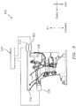
FIG. 3 , asystem 300 is shown. Thesystem 300 may be included as part of an engine, such as for example theengine 10 ofFIG. 1 . - The
system 300 may include afirst device 302 coupled to afirst structure 306 and asecond device 312 coupled to asecond structure 316. In some embodiments, thefirst structure 306 may include one of a bearing compartment structure or an engine case structure and thesecond structure 316 may include the other of the bearing compartment structure or the engine case structure. Thefirst device 302 may include at least one of a physical probe, a laser, an optical transmitter, or any other device that may be configured to generate one or more signals that can be quantified or analyzed. Thesecond device 312 may include a detector/sensor that may be configured to detect the signal(s) generated by thefirst device 302. In this respect, the signal(s) generated/provided by thedevice 302 may serve to stimulate/excite thedevice 312. - The
device 302 and thedevice 312 may be coupled to a computer/controller 324. Thecontroller 324 may include any combination of software, hardware (e.g., one or more processors, memory, etc.), and/or firmware to execute one or more algorithms or functions, such as those described below. - For example, and referring to the flowchart of the
method 400 inFIG. 4 , inblock 406 thecontroller 324 may issue commands to thedevice 302 to cause the device to generate one or more signals. - In
block 412, thecontroller 324 may obtain data from thedevice 312. The receipt of the data inblock 412 may be coordinated/synchronized with the commands issued inblock 406. The data ofblock 412 may be indicative of an alignment of thestructure 306 relative to thestructure 316. - In
block 418, thecontroller 324 may process the data ofblock 412. The processing of the data inblock 418 may include a determination of an alignment of thestructure 306 relative to thestructure 316. For example, the processing ofblock 418 may be based on a proximity and/or intensity of the signal(s) emitted by thedevice 302 in relation to a target point/location on thedevice 312. - In
block 424, based on the processing of the data inblock 418 thecontroller 324 may determine whether thestructure 306 is sufficiently aligned with thestructure 316, such that any skew that may exist between thestructure 306 and thestructure 316 is less than a threshold amount. As an example, and referring toFIG 3A , one ormore nuts 352 may be torqued until an axial point of asurface 356 is concentric to asurface 360 within approximately .003 inches (approximately 76.2 micrometers). If such alignment is obtained (e.g., the "yes" path is taken out of block 424), flow may proceed fromblock 424 to block 430. Otherwise (e.g., the "no" path is taken out of block 424), flow may proceed fromblock 424 to block 436. - In
block 430, an alert may be provided that themethod 400 has completed. The alert may include an auditory alert, a graphical alert (e.g., a displayed message), etc. In some embodiments, the alert ofblock 430 may include an indication of any skew (or any potential range of skew) that may exist in the alignment of thestructures method 400 may be provided as part ofblock 430. - In
block 436, thecontroller 324 may identify one or more nuts to turn/torque by way of activating/enabling one or moretorqueing devices 338. Such an identification may be based on one or more gaps or misalignment between thestructures blocks torqueing device 338 may include one or more electronic motors, servomotors, or the like. As part ofblock 436, thecontroller 324 may also identify an amount of torque to apply to each such nut, or analogously, thecontroller 324 may determine a time duration that thetorqueing device 338 should be activated/enabled. The identifications or determinations provided inblock 436 may attempt to align thestructures system 300. - From
block 436 flow may proceed to block 406. In this manner, a loop may be established betweenblocks structure 306 is sufficiently aligned with thestructure 316. - Referring to
FIG. 5 , asystem 500 incorporating a first structure 506 (which may correspond to the structure 306) and a second structure 516 (which may correspond to the structure 316) is shown. Thefirst structure 506 and thesecond structure 516 may be coupled to one another via one ormore rods 522, forming a hub-and-spoke style of arrangement. Each of therods 522 is shown as being coupled to anut 530. Each of thenuts 530 may be selectively turned/torqued via a respective torqueing device 538 (which may correspond to a torqueing device 338). - Referring now to
FIG. 6 , anillustrative system 600 is shown. Thesystem 600 may be associated with one or more computers and/or one or more controllers (e.g., the controller 324). Thesystem 600 includes one or more processors (generally shown by a processor 602) and amemory 604. Thememory 604 may storedata 606 and/orinstructions 608. Thesystem 600 may include a computer-readable medium (CRM) 610 that may store some or all of theinstructions 608. TheCRM 610 may include a transitory and/or a non-transitory computer-readable medium. - The
instructions 608, when executed by theprocessor 602, may cause the system 600 (or one or more portions thereof) to perform one or more methodological acts or processes, such as those described herein. - The
data 606 may include data obtained from one or more detectors, may include results of processing the data obtained from the detectors, etc. In some embodiments, thedata 606 may be associated with one or more programs, such as a modeling or simulation program. For example, the data may be native to or supported by one or more computed aided design or computer aided drawing programs, either one or both of which may be referred to as CAD programs. Thedata 606 may be used in connection with aligning one or more structures as described herein. - The
system 600 may include one or more input/output (I/O)devices 612 that may be used to provide an interface between thesystem 600 and one or more additional systems or components. The I/O devices 612 may include one or more of a graphical user interface (GUI), a display screen, a touchscreen, a keyboard, a mouse, a joystick, a pushbutton, a microphone, a speaker, a transceiver, a sensor, etc. - Technical effects and benefits of this disclosure include enhanced confidence in the assembly of an engine. For example, aspects of the disclosure may eliminate/minimize technician error by automating an alignment/centering procedure, thereby obtaining more consistent and reliable results. Increased productivity/realization may be obtained, as a technician is merely tasked with set-up and tear-down/breakdown activities.
- Aspects of the disclosure have been described in terms of illustrative embodiments thereof. Numerous other embodiments, modifications, and variations within the scope and spirit of the appended claims will occur to persons of ordinary skill in the art from a review of this disclosure. For example, one of ordinary skill in the art will appreciate that the steps described in conjunction with the illustrative figures may be performed in other than the recited order, and that one or more steps illustrated may be optional in accordance with aspects of the disclosure. One or more features described in connection with a first embodiment may be combined with one or more features of one or more additional embodiments.
Claims (15)
- A method for aligning a bearing compartment structure (306) relative to an engine case structure (316), the method comprising:issuing, by a controller (324) that includes a processor (602), a command to a first device (302) to generate a signal;obtaining, by the controller (324), data from a second device (312) that is based on the signal;processing, by the controller (324), the data to determine that a skew exists between the bearing compartment structure (306) and the engine case structure (316) in an amount that is greater than a threshold;identifying, by the controller (324), at least one torqueing device (338) to activate based on said processing; andcausing, by the controller (324), the at least one torqueing device (338) to activate to cause the bearing compartment structure (306) and the engine case structure (316) to align within the threshold amount.
- The method of claim 1, wherein the first device (302) is coupled to the bearing compartment structure (306) and the second device (312) is coupled to the engine case structure (316).
- The method of claim 1 or 2, wherein the at least one torqueing device (338) includes at least one of an electronic motor or a servomotor.
- The method of claim 1, 2 or 3, further comprising:identifying, by the controller (324), an amount of torque to apply to a nut (530) coupled to the at least one torqueing device (338); andcausing, by the controller (324), the at least one torqueing device (338) to apply torque to the nut (530) in accordance with the identified amount.
- The method of any preceding claim, further comprising:identifying, by the controller (324), a time duration to activate the at least one torqueing device (338);causing, by the controller (324), the at least one torqueing device (338) to activate in accordance with the time duration; andcausing, by the controller (324), the at least one torqueing device (338) to deactivate at an end of the time duration.
- A system for aligning a bearing compartment structure (306) relative to an engine case structure (316), the system comprising:a first device (302) coupled to the bearing compartment structure (306);a second device (312) coupled to the engine case structure (316); anda controller (324) configured to:issue a command to one of the first device (302) or the second device (312) to generate a signal;obtain data from the other of the one of the first device (302) or the second device (312), wherein the data is based on the signal;process the data to determine that a skew exists between the bearing compartment structure (306) and the engine case structure (316) in an amount that is greater than a threshold;identify at least one torqueing device (338) to activate based on processing the data; andcause the at least one torqueing device (338) to activate to cause the bearing compartment structure (316) and the engine case structure (306) to align within the threshold amount.
- The system of claim 6, further comprising:the at least one torqueing device (338).
- The system of claim 7, further comprising:a threaded rod (522) that couples the bearing compartment structure (306) and the engine case structure (312); and optionally:a nut (530) coupled to the rod (522) and the at least one torqueing device (338), wherein optionally the at least one torqueing device (338) is configured to apply torque to the nut (530) when the at least one torqueing device (338) is activated.
- The system of claim 8, wherein a first end of the rod (530) is coupled to the bearing compartment structure (306) and a second end of the rod (530) is coupled to the engine case structure (316).
- The system of claim 7, 8 or 9, wherein the at least one torqueing device (338) includes at least one of an electronic motor or a servomotor.
- The system of any of claims 6-10, wherein the controller (324) is configured to issue the command to the first device (302) and obtain the data from the second device (312).
- The system of any of claims 6-11, wherein the controller (324) is configured to provide an alert when the controller (324) determines that the bearing compartment structure (306) and the engine case structure (316) align within the threshold amount.
- The system of any of claims 6-12, wherein the at least one torqueing device (338) includes a plurality of torqueing devices (538), the system further comprising:a plurality of threaded rods (522) that couple the bearing compartment structure (306) and the engine case structure (316); anda plurality of nuts (530),wherein each one of the nuts (530) is coupled to a respective one of the rods (522), andwherein each one of the torqueing devices (538) is coupled to a respective one of the nuts (530).
- The method of any of claims 1-5, or the system of any of claims 6-13, wherein the first device (302) includes at least one of a physical probe, a laser, or an optical transmitter.
- The method of any of claims 1-5 or 14, or the system of any of claims 6-14, wherein the first device (302) includes a laser, and wherein the second device (312) includes a laser detector.
Applications Claiming Priority (1)
| Application Number | Priority Date | Filing Date | Title |
|---|---|---|---|
| US15/004,605 US10337355B2 (en) | 2016-01-22 | 2016-01-22 | Alignment of a bearing compartment and an engine case |
Publications (2)
| Publication Number | Publication Date |
|---|---|
| EP3196421A1 true EP3196421A1 (en) | 2017-07-26 |
| EP3196421B1 EP3196421B1 (en) | 2019-05-15 |
Family
ID=57909455
Family Applications (1)
| Application Number | Title | Priority Date | Filing Date |
|---|---|---|---|
| EP17152611.4A Active EP3196421B1 (en) | 2016-01-22 | 2017-01-23 | Alignment of a bearing compartment and an engine case |
Country Status (2)
| Country | Link |
|---|---|
| US (1) | US10337355B2 (en) |
| EP (1) | EP3196421B1 (en) |
Families Citing this family (1)
| Publication number | Priority date | Publication date | Assignee | Title |
|---|---|---|---|---|
| FR3155447B1 (en) * | 2023-11-20 | 2025-10-17 | Safran Aircraft Engines | TOOL FOR CENTERING AN ANNULAR PART |
Citations (4)
| Publication number | Priority date | Publication date | Assignee | Title |
|---|---|---|---|---|
| EP1655457A1 (en) * | 2004-10-29 | 2006-05-10 | General Electric Company | Gas turbine engine and method of assembling same |
| US20100296912A1 (en) * | 2009-05-22 | 2010-11-25 | General Electric Company | Active Rotor Alignment Control System And Method |
| WO2014113034A1 (en) * | 2013-01-21 | 2014-07-24 | United Technologies Corporation | Turbine case adjustment using adjustable tie rods |
| WO2014137574A1 (en) * | 2013-03-05 | 2014-09-12 | United Technologies Corporation | Mid-turbine frame rod and turbine case flange |
Family Cites Families (10)
| Publication number | Priority date | Publication date | Assignee | Title |
|---|---|---|---|---|
| US2650050A (en) | 1948-06-17 | 1953-08-25 | Niles Bement Pond Co | Movable mount for aircraft engines |
| US3876309A (en) | 1973-10-01 | 1975-04-08 | Joseph P Zicaro | Automatically adjustable laser beam positioning apparatus |
| CH672839A5 (en) | 1987-01-19 | 1989-12-29 | Ammann Lasertechnik | |
| DE10325859B3 (en) * | 2003-06-06 | 2004-06-03 | Hilti Ag | Rotational laser has deflection device for laser beam supported by spherical pivot mounting allowing laser beam rotational plane to be angled |
| US20080297808A1 (en) * | 2005-12-06 | 2008-12-04 | Nabeel Agha Riza | Optical Sensor For Extreme Environments |
| SG157975A1 (en) | 2008-06-18 | 2010-01-29 | Mfg Integration Technology Ltd | Adaptive clamp width adjusting device |
| US9238973B2 (en) * | 2009-12-29 | 2016-01-19 | Rolls-Royce Corporation | Gas turbine engine and foil bearing system |
| US20110277569A1 (en) * | 2010-05-14 | 2011-11-17 | Douglas Rush | Instrumentation fitting |
| US9845705B2 (en) | 2014-01-07 | 2017-12-19 | United Technologies Corporation | Systems and methods for centering bearing compartments |
| US9739301B2 (en) | 2014-01-07 | 2017-08-22 | United Technologies Corporation | Systems and methods for centering bearing compartments |
-
2016
- 2016-01-22 US US15/004,605 patent/US10337355B2/en active Active
-
2017
- 2017-01-23 EP EP17152611.4A patent/EP3196421B1/en active Active
Patent Citations (4)
| Publication number | Priority date | Publication date | Assignee | Title |
|---|---|---|---|---|
| EP1655457A1 (en) * | 2004-10-29 | 2006-05-10 | General Electric Company | Gas turbine engine and method of assembling same |
| US20100296912A1 (en) * | 2009-05-22 | 2010-11-25 | General Electric Company | Active Rotor Alignment Control System And Method |
| WO2014113034A1 (en) * | 2013-01-21 | 2014-07-24 | United Technologies Corporation | Turbine case adjustment using adjustable tie rods |
| WO2014137574A1 (en) * | 2013-03-05 | 2014-09-12 | United Technologies Corporation | Mid-turbine frame rod and turbine case flange |
Also Published As
| Publication number | Publication date |
|---|---|
| US10337355B2 (en) | 2019-07-02 |
| EP3196421B1 (en) | 2019-05-15 |
| US20170211423A1 (en) | 2017-07-27 |
Similar Documents
| Publication | Publication Date | Title |
|---|---|---|
| EP3034812B1 (en) | Torque sensor monitoring for gas turbine engine | |
| US8794920B2 (en) | Controlling blade pitch angle | |
| US9228915B2 (en) | Method and system for detecting a flow blockage in a pipe | |
| EP2055904A2 (en) | Foreign object/domestic object damage assessment in a turbomachine | |
| US8869603B2 (en) | Debris detection in turbomachinery and gas turbine engines | |
| KR20130090849A (en) | A method and a device for performing a health check of a turbine engine of an aircraft having at least one such engine | |
| CN103775139A (en) | Gap control system and method for turbine engine | |
| CN104697798A (en) | System and method for three-dimensional characterization of blade tip gaps and dynamic detection of optical fibers of aero-engine | |
| CN110470381A (en) | A method of verifying blade synchronization vibration parameters identification algorithm accuracy | |
| US11667392B2 (en) | Method and system for operating a rotorcraft engine | |
| EP3309374B1 (en) | Starter issue detection | |
| EP3196421B1 (en) | Alignment of a bearing compartment and an engine case | |
| US20020168260A1 (en) | Optical stall precursor sensor apparatus and method for application on axial flow compressors | |
| US10683810B2 (en) | Shaft shear detection for gas turbine engines | |
| CN116577791A (en) | System and method for inspecting fan blade tip clearance relative to an abradable fan case | |
| Kielb et al. | Experimental and numerical study of forced response in a full-scale rotating turbine | |
| Chen et al. | Analysis of engine blade chipping fault based on vibration and stress testing fusion | |
| US20070245746A1 (en) | Methods and systems for detecting rotor assembly speed oscillation in turbine engines | |
| US9897431B2 (en) | Edge detector | |
| CN105043775B (en) | A kind of aero-engine critical system hazard analysis system and method | |
| US12252995B2 (en) | Acoustical health monitoring of gas turbine engines | |
| US11168635B2 (en) | Methods and systems for assessing engine health | |
| CN119062456A (en) | A method for assisting in judging afterburner flameout using aircraft engine main engine parameters | |
| Cai et al. | Numerical Simulation of Dynamic Characteristics Based on Radiation Temperature Probe | |
| CN117516944A (en) | A wireless telemetry lead device for measuring axial flow compressor blade table parameters |
Legal Events
| Date | Code | Title | Description |
|---|---|---|---|
| PUAI | Public reference made under article 153(3) epc to a published international application that has entered the european phase |
Free format text: ORIGINAL CODE: 0009012 |
|
| STAA | Information on the status of an ep patent application or granted ep patent |
Free format text: STATUS: THE APPLICATION HAS BEEN PUBLISHED |
|
| AK | Designated contracting states |
Kind code of ref document: A1 Designated state(s): AL AT BE BG CH CY CZ DE DK EE ES FI FR GB GR HR HU IE IS IT LI LT LU LV MC MK MT NL NO PL PT RO RS SE SI SK SM TR |
|
| AX | Request for extension of the european patent |
Extension state: BA ME |
|
| STAA | Information on the status of an ep patent application or granted ep patent |
Free format text: STATUS: REQUEST FOR EXAMINATION WAS MADE |
|
| 17P | Request for examination filed |
Effective date: 20180125 |
|
| RBV | Designated contracting states (corrected) |
Designated state(s): AL AT BE BG CH CY CZ DE DK EE ES FI FR GB GR HR HU IE IS IT LI LT LU LV MC MK MT NL NO PL PT RO RS SE SI SK SM TR |
|
| GRAP | Despatch of communication of intention to grant a patent |
Free format text: ORIGINAL CODE: EPIDOSNIGR1 |
|
| STAA | Information on the status of an ep patent application or granted ep patent |
Free format text: STATUS: GRANT OF PATENT IS INTENDED |
|
| RIC1 | Information provided on ipc code assigned before grant |
Ipc: F01D 25/04 20060101AFI20181105BHEP Ipc: F01D 25/16 20060101ALI20181105BHEP |
|
| INTG | Intention to grant announced |
Effective date: 20181123 |
|
| GRAS | Grant fee paid |
Free format text: ORIGINAL CODE: EPIDOSNIGR3 |
|
| GRAA | (expected) grant |
Free format text: ORIGINAL CODE: 0009210 |
|
| STAA | Information on the status of an ep patent application or granted ep patent |
Free format text: STATUS: THE PATENT HAS BEEN GRANTED |
|
| AK | Designated contracting states |
Kind code of ref document: B1 Designated state(s): AL AT BE BG CH CY CZ DE DK EE ES FI FR GB GR HR HU IE IS IT LI LT LU LV MC MK MT NL NO PL PT RO RS SE SI SK SM TR |
|
| REG | Reference to a national code |
Ref country code: CH Ref legal event code: EP |
|
| REG | Reference to a national code |
Ref country code: DE Ref legal event code: R096 Ref document number: 602017003803 Country of ref document: DE |
|
| REG | Reference to a national code |
Ref country code: IE Ref legal event code: FG4D |
|
| REG | Reference to a national code |
Ref country code: NL Ref legal event code: MP Effective date: 20190515 |
|
| REG | Reference to a national code |
Ref country code: LT Ref legal event code: MG4D |
|
| PG25 | Lapsed in a contracting state [announced via postgrant information from national office to epo] |
Ref country code: FI Free format text: LAPSE BECAUSE OF FAILURE TO SUBMIT A TRANSLATION OF THE DESCRIPTION OR TO PAY THE FEE WITHIN THE PRESCRIBED TIME-LIMIT Effective date: 20190515 Ref country code: NL Free format text: LAPSE BECAUSE OF FAILURE TO SUBMIT A TRANSLATION OF THE DESCRIPTION OR TO PAY THE FEE WITHIN THE PRESCRIBED TIME-LIMIT Effective date: 20190515 Ref country code: SE Free format text: LAPSE BECAUSE OF FAILURE TO SUBMIT A TRANSLATION OF THE DESCRIPTION OR TO PAY THE FEE WITHIN THE PRESCRIBED TIME-LIMIT Effective date: 20190515 Ref country code: LT Free format text: LAPSE BECAUSE OF FAILURE TO SUBMIT A TRANSLATION OF THE DESCRIPTION OR TO PAY THE FEE WITHIN THE PRESCRIBED TIME-LIMIT Effective date: 20190515 Ref country code: AL Free format text: LAPSE BECAUSE OF FAILURE TO SUBMIT A TRANSLATION OF THE DESCRIPTION OR TO PAY THE FEE WITHIN THE PRESCRIBED TIME-LIMIT Effective date: 20190515 Ref country code: ES Free format text: LAPSE BECAUSE OF FAILURE TO SUBMIT A TRANSLATION OF THE DESCRIPTION OR TO PAY THE FEE WITHIN THE PRESCRIBED TIME-LIMIT Effective date: 20190515 Ref country code: PT Free format text: LAPSE BECAUSE OF FAILURE TO SUBMIT A TRANSLATION OF THE DESCRIPTION OR TO PAY THE FEE WITHIN THE PRESCRIBED TIME-LIMIT Effective date: 20190915 Ref country code: NO Free format text: LAPSE BECAUSE OF FAILURE TO SUBMIT A TRANSLATION OF THE DESCRIPTION OR TO PAY THE FEE WITHIN THE PRESCRIBED TIME-LIMIT Effective date: 20190815 Ref country code: HR Free format text: LAPSE BECAUSE OF FAILURE TO SUBMIT A TRANSLATION OF THE DESCRIPTION OR TO PAY THE FEE WITHIN THE PRESCRIBED TIME-LIMIT Effective date: 20190515 |
|
| PG25 | Lapsed in a contracting state [announced via postgrant information from national office to epo] |
Ref country code: LV Free format text: LAPSE BECAUSE OF FAILURE TO SUBMIT A TRANSLATION OF THE DESCRIPTION OR TO PAY THE FEE WITHIN THE PRESCRIBED TIME-LIMIT Effective date: 20190515 Ref country code: BG Free format text: LAPSE BECAUSE OF FAILURE TO SUBMIT A TRANSLATION OF THE DESCRIPTION OR TO PAY THE FEE WITHIN THE PRESCRIBED TIME-LIMIT Effective date: 20190815 Ref country code: GR Free format text: LAPSE BECAUSE OF FAILURE TO SUBMIT A TRANSLATION OF THE DESCRIPTION OR TO PAY THE FEE WITHIN THE PRESCRIBED TIME-LIMIT Effective date: 20190816 Ref country code: RS Free format text: LAPSE BECAUSE OF FAILURE TO SUBMIT A TRANSLATION OF THE DESCRIPTION OR TO PAY THE FEE WITHIN THE PRESCRIBED TIME-LIMIT Effective date: 20190515 |
|
| REG | Reference to a national code |
Ref country code: AT Ref legal event code: MK05 Ref document number: 1133684 Country of ref document: AT Kind code of ref document: T Effective date: 20190515 |
|
| PG25 | Lapsed in a contracting state [announced via postgrant information from national office to epo] |
Ref country code: CZ Free format text: LAPSE BECAUSE OF FAILURE TO SUBMIT A TRANSLATION OF THE DESCRIPTION OR TO PAY THE FEE WITHIN THE PRESCRIBED TIME-LIMIT Effective date: 20190515 Ref country code: EE Free format text: LAPSE BECAUSE OF FAILURE TO SUBMIT A TRANSLATION OF THE DESCRIPTION OR TO PAY THE FEE WITHIN THE PRESCRIBED TIME-LIMIT Effective date: 20190515 Ref country code: DK Free format text: LAPSE BECAUSE OF FAILURE TO SUBMIT A TRANSLATION OF THE DESCRIPTION OR TO PAY THE FEE WITHIN THE PRESCRIBED TIME-LIMIT Effective date: 20190515 Ref country code: AT Free format text: LAPSE BECAUSE OF FAILURE TO SUBMIT A TRANSLATION OF THE DESCRIPTION OR TO PAY THE FEE WITHIN THE PRESCRIBED TIME-LIMIT Effective date: 20190515 Ref country code: SK Free format text: LAPSE BECAUSE OF FAILURE TO SUBMIT A TRANSLATION OF THE DESCRIPTION OR TO PAY THE FEE WITHIN THE PRESCRIBED TIME-LIMIT Effective date: 20190515 |
|
| REG | Reference to a national code |
Ref country code: DE Ref legal event code: R097 Ref document number: 602017003803 Country of ref document: DE |
|
| PG25 | Lapsed in a contracting state [announced via postgrant information from national office to epo] |
Ref country code: SM Free format text: LAPSE BECAUSE OF FAILURE TO SUBMIT A TRANSLATION OF THE DESCRIPTION OR TO PAY THE FEE WITHIN THE PRESCRIBED TIME-LIMIT Effective date: 20190515 Ref country code: IT Free format text: LAPSE BECAUSE OF FAILURE TO SUBMIT A TRANSLATION OF THE DESCRIPTION OR TO PAY THE FEE WITHIN THE PRESCRIBED TIME-LIMIT Effective date: 20190515 |
|
| PLBE | No opposition filed within time limit |
Free format text: ORIGINAL CODE: 0009261 |
|
| STAA | Information on the status of an ep patent application or granted ep patent |
Free format text: STATUS: NO OPPOSITION FILED WITHIN TIME LIMIT |
|
| PG25 | Lapsed in a contracting state [announced via postgrant information from national office to epo] |
Ref country code: TR Free format text: LAPSE BECAUSE OF FAILURE TO SUBMIT A TRANSLATION OF THE DESCRIPTION OR TO PAY THE FEE WITHIN THE PRESCRIBED TIME-LIMIT Effective date: 20190515 |
|
| 26N | No opposition filed |
Effective date: 20200218 |
|
| PG25 | Lapsed in a contracting state [announced via postgrant information from national office to epo] |
Ref country code: PL Free format text: LAPSE BECAUSE OF FAILURE TO SUBMIT A TRANSLATION OF THE DESCRIPTION OR TO PAY THE FEE WITHIN THE PRESCRIBED TIME-LIMIT Effective date: 20190515 |
|
| PG25 | Lapsed in a contracting state [announced via postgrant information from national office to epo] |
Ref country code: SI Free format text: LAPSE BECAUSE OF FAILURE TO SUBMIT A TRANSLATION OF THE DESCRIPTION OR TO PAY THE FEE WITHIN THE PRESCRIBED TIME-LIMIT Effective date: 20190515 |
|
| PG25 | Lapsed in a contracting state [announced via postgrant information from national office to epo] |
Ref country code: MC Free format text: LAPSE BECAUSE OF FAILURE TO SUBMIT A TRANSLATION OF THE DESCRIPTION OR TO PAY THE FEE WITHIN THE PRESCRIBED TIME-LIMIT Effective date: 20190515 |
|
| REG | Reference to a national code |
Ref country code: CH Ref legal event code: PL |
|
| REG | Reference to a national code |
Ref country code: BE Ref legal event code: MM Effective date: 20200131 |
|
| PG25 | Lapsed in a contracting state [announced via postgrant information from national office to epo] |
Ref country code: LU Free format text: LAPSE BECAUSE OF NON-PAYMENT OF DUE FEES Effective date: 20200123 |
|
| PG25 | Lapsed in a contracting state [announced via postgrant information from national office to epo] |
Ref country code: CH Free format text: LAPSE BECAUSE OF NON-PAYMENT OF DUE FEES Effective date: 20200131 Ref country code: LI Free format text: LAPSE BECAUSE OF NON-PAYMENT OF DUE FEES Effective date: 20200131 Ref country code: BE Free format text: LAPSE BECAUSE OF NON-PAYMENT OF DUE FEES Effective date: 20200131 |
|
| PG25 | Lapsed in a contracting state [announced via postgrant information from national office to epo] |
Ref country code: IE Free format text: LAPSE BECAUSE OF NON-PAYMENT OF DUE FEES Effective date: 20200123 |
|
| PG25 | Lapsed in a contracting state [announced via postgrant information from national office to epo] |
Ref country code: MT Free format text: LAPSE BECAUSE OF FAILURE TO SUBMIT A TRANSLATION OF THE DESCRIPTION OR TO PAY THE FEE WITHIN THE PRESCRIBED TIME-LIMIT Effective date: 20190515 Ref country code: CY Free format text: LAPSE BECAUSE OF FAILURE TO SUBMIT A TRANSLATION OF THE DESCRIPTION OR TO PAY THE FEE WITHIN THE PRESCRIBED TIME-LIMIT Effective date: 20190515 |
|
| PG25 | Lapsed in a contracting state [announced via postgrant information from national office to epo] |
Ref country code: RO Free format text: LAPSE BECAUSE OF FAILURE TO SUBMIT A TRANSLATION OF THE DESCRIPTION OR TO PAY THE FEE WITHIN THE PRESCRIBED TIME-LIMIT Effective date: 20190515 Ref country code: MK Free format text: LAPSE BECAUSE OF FAILURE TO SUBMIT A TRANSLATION OF THE DESCRIPTION OR TO PAY THE FEE WITHIN THE PRESCRIBED TIME-LIMIT Effective date: 20190515 Ref country code: IS Free format text: LAPSE BECAUSE OF FAILURE TO SUBMIT A TRANSLATION OF THE DESCRIPTION OR TO PAY THE FEE WITHIN THE PRESCRIBED TIME-LIMIT Effective date: 20190915 |
|
| REG | Reference to a national code |
Ref country code: DE Ref legal event code: R081 Ref document number: 602017003803 Country of ref document: DE Owner name: RAYTHEON TECHNOLOGIES CORPORATION (N.D.GES.D.S, US Free format text: FORMER OWNER: UNITED TECHNOLOGIES CORPORATION, FARMINGTON, CONN., US Ref country code: DE Ref legal event code: R081 Ref document number: 602017003803 Country of ref document: DE Owner name: RTX CORPORATION (N.D.GES.D. STAATES DELAWARE),, US Free format text: FORMER OWNER: UNITED TECHNOLOGIES CORPORATION, FARMINGTON, CONN., US |
|
| P01 | Opt-out of the competence of the unified patent court (upc) registered |
Effective date: 20230520 |
|
| REG | Reference to a national code |
Ref country code: DE Ref legal event code: R081 Ref document number: 602017003803 Country of ref document: DE Owner name: RTX CORPORATION (N.D.GES.D. STAATES DELAWARE),, US Free format text: FORMER OWNER: RAYTHEON TECHNOLOGIES CORPORATION (N.D.GES.D.STAATES DELAWARE), ARLINGTON, VA, US |
|
| PGFP | Annual fee paid to national office [announced via postgrant information from national office to epo] |
Ref country code: GB Payment date: 20251220 Year of fee payment: 10 |
|
| PGFP | Annual fee paid to national office [announced via postgrant information from national office to epo] |
Ref country code: FR Payment date: 20251217 Year of fee payment: 10 |
|
| PGFP | Annual fee paid to national office [announced via postgrant information from national office to epo] |
Ref country code: DE Payment date: 20251217 Year of fee payment: 10 |