EP3196403A1 - Feed apparatus and method for feeding cement to a cement silo - Google Patents
Feed apparatus and method for feeding cement to a cement silo Download PDFInfo
- Publication number
- EP3196403A1 EP3196403A1 EP16152020.0A EP16152020A EP3196403A1 EP 3196403 A1 EP3196403 A1 EP 3196403A1 EP 16152020 A EP16152020 A EP 16152020A EP 3196403 A1 EP3196403 A1 EP 3196403A1
- Authority
- EP
- European Patent Office
- Prior art keywords
- cement
- transfer tube
- receptacle
- feed apparatus
- silo
- Prior art date
- Legal status (The legal status is an assumption and is not a legal conclusion. Google has not performed a legal analysis and makes no representation as to the accuracy of the status listed.)
- Granted
Links
Images

Classifications
-
- E—FIXED CONSTRUCTIONS
- E21—EARTH OR ROCK DRILLING; MINING
- E21D—SHAFTS; TUNNELS; GALLERIES; LARGE UNDERGROUND CHAMBERS
- E21D20/00—Setting anchoring-bolts
- E21D20/02—Setting anchoring-bolts with provisions for grouting
- E21D20/021—Grouting with inorganic components, e.g. cement
-
- E—FIXED CONSTRUCTIONS
- E21—EARTH OR ROCK DRILLING; MINING
- E21B—EARTH OR ROCK DRILLING; OBTAINING OIL, GAS, WATER, SOLUBLE OR MELTABLE MATERIALS OR A SLURRY OF MINERALS FROM WELLS
- E21B27/00—Containers for collecting or depositing substances in boreholes or wells, e.g. bailers, baskets or buckets for collecting mud or sand; Drill bits with means for collecting substances, e.g. valve drill bits
- E21B27/04—Containers for collecting or depositing substances in boreholes or wells, e.g. bailers, baskets or buckets for collecting mud or sand; Drill bits with means for collecting substances, e.g. valve drill bits where the collecting or depositing means include helical conveying means
-
- B—PERFORMING OPERATIONS; TRANSPORTING
- B65—CONVEYING; PACKING; STORING; HANDLING THIN OR FILAMENTARY MATERIAL
- B65G—TRANSPORT OR STORAGE DEVICES, e.g. CONVEYORS FOR LOADING OR TIPPING, SHOP CONVEYOR SYSTEMS OR PNEUMATIC TUBE CONVEYORS
- B65G33/00—Screw or rotary spiral conveyors
- B65G33/08—Screw or rotary spiral conveyors for fluent solid materials
- B65G33/14—Screw or rotary spiral conveyors for fluent solid materials comprising a screw or screws enclosed in a tubular housing
-
- E—FIXED CONSTRUCTIONS
- E21—EARTH OR ROCK DRILLING; MINING
- E21B—EARTH OR ROCK DRILLING; OBTAINING OIL, GAS, WATER, SOLUBLE OR MELTABLE MATERIALS OR A SLURRY OF MINERALS FROM WELLS
- E21B7/00—Special methods or apparatus for drilling
- E21B7/02—Drilling rigs characterised by means for land transport with their own drive, e.g. skid mounting or wheel mounting
-
- E—FIXED CONSTRUCTIONS
- E21—EARTH OR ROCK DRILLING; MINING
- E21D—SHAFTS; TUNNELS; GALLERIES; LARGE UNDERGROUND CHAMBERS
- E21D11/00—Lining tunnels, galleries or other underground cavities, e.g. large underground chambers; Linings therefor; Making such linings in situ, e.g. by assembling
- E21D11/04—Lining with building materials
- E21D11/10—Lining with building materials with concrete cast in situ; Shuttering also lost shutterings, e.g. made of blocks, of metal plates or other equipment adapted therefor
-
- E—FIXED CONSTRUCTIONS
- E21—EARTH OR ROCK DRILLING; MINING
- E21D—SHAFTS; TUNNELS; GALLERIES; LARGE UNDERGROUND CHAMBERS
- E21D20/00—Setting anchoring-bolts
- E21D20/02—Setting anchoring-bolts with provisions for grouting
-
- E—FIXED CONSTRUCTIONS
- E21—EARTH OR ROCK DRILLING; MINING
- E21F—SAFETY DEVICES, TRANSPORT, FILLING-UP, RESCUE, VENTILATION, OR DRAINING IN OR OF MINES OR TUNNELS
- E21F15/00—Methods or devices for placing filling-up materials in underground workings
- E21F15/005—Methods or devices for placing filling-up materials in underground workings characterised by the kind or composition of the backfilling material
Definitions
- the invention relates to a feed apparatus and a method for feeding cement to a cement silo, more particularly to feeding cement to a cement silo attached to a mining machine.
- cement silo In mining there are used grouting apparatuses both for grouting bolts in holes drilled for them and for injecting cement in holes or various fragmented rocks. Cement is usually fed from a lower part of a cement silo to a mixer, in which mixer the cement is mixed with water to produce grouting concrete. Typically, the cement silo is located on top of the mining machine, where it is relatively high up, whereby charging cement into the feed silo is hard, complicated and produces dust. Additionally, it often requires manual assistance especially in underground mines with limited space available requiring a separate working platform usually reached by a ladder and may even concern cement sacks being lifted by manpower, which all may further risk the occupational safety of the operators.
- An object of the present solution is to provide a new method and a feed apparatus for feeding cement to a cement silo of a mining machine for implementing the method.
- the objects of the solution are achieved by a method and a feed apparatus, which are characterized by what is stated in the independent claims. Some embodiments of the invention are disclosed in the dependent claims.
- the solution is based on the idea of providing the feed apparatus with a receptacle, a transfer tube and transfer means arranged to move cement within the transfer tube from the receptacle to the cement silo. This enables selecting more freely the point at which the cement is fed to the mining machine. This is very beneficial, because the space in mining tunnels is typically very limited and because of the problems related to feeding the cement directly to the cement silo typically positioned on top of the mining machine can be avoided.
- FIG. 1 shows a mining machine 1.
- the mining machine 1 may comprise any mining machine comprising means for providing grouting concrete to holes, splits and/or other cavities of a rock. Different embodiments such mining machines 1 and means 4 for providing grouting concrete in cavities provided in a rock are known as such.
- the mining machine 1 may also comprise a mixer 11 for mixing cement and water for producing the grouting concrete and a cement silo 2 through which the cement is fed to the mixer 11.
- the mining machine 1 of Figure 1 also comprises a feed apparatus 3 for feeding cement to the cement silo 2 of the mining machine 1.
- the feed apparatus 3 may comprise a receptacle 5 for receiving cement.
- the receptacle 5 may comprise a scoop-like container, wherein an opening 5a is arranged at the top of the receptacle 5 for receiving cement. This enables easy filling of the cement to the receptacle 5.
- the feed apparatus 3 may further comprise a transfer tube 6 connected at a first end 6a to the receptacle 5 and connectable at a second end 6b to the cement silo 2 for guiding the cement from the receptacle 5 to the cement silo 2.
- the transfer tube 6 may be fixedly or removably attached to the receptacle 5 and/or the cement silo 2 for feeding cement to the cement silo 2.
- the transfer tube 6 may comprise at least one transfer tube section comprising a tube-like inner space for cement to be transferred.
- the transfer tube 6 enables positioning of the receptacle 5 for receiving cement at a desired position and, therefore, possibility for a more safe and convenient feeding of cement, as the cement does not need to be fed directly to the cement silo 2 or a receptacle provided above the cement silo 2.
- the transfer tube 6 may comprise a transfer tube section and a connector part 6c for connecting the transfer tube 6 to the cement silo 2.
- the transfer tube 6 may further comprise a second transfer tube section.
- the transfer tube 6 may comprise at least two transfer tube sections arranged at an angle with respect to one another.
- At least a part of a transfer tube section of the transfer tube 6 may be formed as flexible at least in the transverse direction of the transfer tube section.
- the transverse direction of the transfer tube section may comprise a direction substantially perpendicular to the longitudinal direction of the transfer tube section.
- the at least part of the transfer tube section may be forms as flexible by the transfer tube section comprising a flexible material and/or a flexible structure.
- the receptacle 5 may be provided as a fixed part of the feed apparatus 3.
- the receptacle 5 may comprise a separate unit that is removably arrangeable to the transfer tube 6.
- Different types of arrangements for removably arranging a receptacle to other structural parts are known as such and are not described here in more detail.
- the receptacle 5 may be formed to be lifted to its use position by a fork-lift or other lifting apparatus known per se.
- Different types of lifting structures, such as lifting holes, lifting fixtures, lifting lugs, lifting hooks and the like are well known and are not described here in more detail.
- the feed apparatus 3 may further comprise transfer means 12 arranged in connection with the transfer tube 6 and arranged to move cement within the transfer tube 6 from the receptacle 5 to the cement silo 2.
- the transfer means 12 may, thus, be arranged at least partly within the transfer tube 6 and/or at least partly surrounding at least one end of the transfer tube 6 or a point along the length of the transfer tube 6.
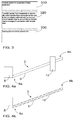
- the transfer means 12 may comprise a screw conveyor, such as it is schematically shown if Figure 4b .
- the transfer means 12 may, thus, be arranged within the transfer tube 6.
- the transfer means 12 may comprise an ejector, such as is schematically shown in Figure 4a .
- the transfer means 12 may, thus, be arranged at least partly surrounding a point along the length of the transfer tube 6 and in fluid connection with it.
- Ejectors refer to pneumatic conveyors where overpressure and/or underpressure is used to provide a force moving a material.
- overpressure may be provided at the first end 6a and/or underpressure may be provided at the second end 6b, such that the pressure difference between the first end 6a and the second end 6b of the transfer tube 6 pushes or pulls the cement within the transfer tube 6 from the receptacle 5 to the cement silo 2.
- Ejectors and pneumatic conveyors as well as ways of providing overpressure and/or underpressure in connection with ejectors and pneumatic conveyors are known as such.
- the overpressure may be provided by some type of a blower and/or the underpressure may be provided by a suction compressor, for example.
- a benefit of such an embodiment is that it works well also with transfer tubes 6 that are not straight as shown in the figures but comprise tube sections arranged at an angle with respect to one another or comprise bends of some other type.
- the transfer means may comprise any other apparatus and/or structure known per se and suitable for transferring cement inside a transfer tube also in an upwards inclined direction.
- a feed apparatus 3 may be arrangeable in at least two alternative positions with respect to the mining machine 1, such as in a first position comprising a tramming position and a second position comprising a use position.
- Figure 1 shows an embodiment of such a feed apparatus 3 shown in first position and
- Figure 2 shows in a second position.
- the position of the receptacle 5 relative to a frame part 7 of the mining machine 1 in the tramming position may be closer to the midpoint of the mining machine 1 than in the use position in at least a vertical direction or a horizontal direction to optimise the overall dimensions of the mining machine.
- the position of the receptacle 5 relative to the frame part 7 of the mining machine 1 in the use position may similarly be located further away from the midpoint of the mining machine 1 than in the tramming position in at least a vertical direction or a horizontal direction to optimise the ease of feeding cement to the receptacle 5.
- the receptacle 5 may be provided in a use position lower and more to the side from the longitudinal centre line of the mining machine 1, whereby the receptacle 5 is easily available for feeding cement. In a tramming position with the receptacle 5 provided closer to the longitudinal centre line and higher up from the mine floor the mining machine 1 may require less space when tramming in the tunnels and the receptacle 5 is less exposed to impacts.
- the feed apparatus 3 may further comprise lifting means (not shown) for moving at least the first end 6a of the transfer tube 6 relative to the frame part 7 of the mining machine 1 and thereby moving the feed apparatus 3 between the use position and the tramming position.
- the use position and the tramming position may comprise a use position and a tramming position as described above.
- the lifting means may comprise at least a pressure medium cylinder. Principles of such pressure medium cylinders are known as such and, thus, they are not explained in more detail.
- the receptacle 5 is arranged in the vicinity of the back end 8 side of the mining machine 1.
- the receptacle 5 is arranged closer to the back end 8 of the mining machine 1, the back end 8 referring to the end of the mining machine 1 opposite to the end comprising means for providing grouting concrete.
- a cement silo 2 according to the current solution may comprise a cover section 9 at the upper end of the cement silo 2 and at the cover section 9 a connecting part 10 shaped to be connected and sealed to a feed apparatus described in this description in a substantially dustproof manner.
- the transfer tube 3 may be connected and sealed to the connecting part 10 of the cover section 9. If the transfer tube 3 comprises a connector part 6c, the connector part 6c of the transfer tube 3 and the connecting part 10 of the cover section 9 of the cover section 9 of the cement silo 2 may be connected and sealed to one another. The sealing is not necessary in all circumstances, but it further decreases presence of dust in the air and, thus, improves the working conditions.
- a method for supplying cement to a cement silo 2 attached to a mining machine 1 may comprise receiving 310 cement in a receptacle 5 of a feed apparatus 3. The method may further comprise transferring 320 the cement from the receptacle to the cement silo within a transfer tube connected at a first end to the receptacle and connected at a second end of the transfer tube to the cement silo by transfer means arranged in connection with the transfer tube, and feeding 330 the cement to the cement silo.
- the transfer tube 6 may comprise at least one transfer tube section comprising a tube-like inner space for cement to be transferred. Any feed apparatus 3 and/or a part thereof described in this description may be used in connection with the method.
- the receptacle 5 may be provided at the back end 8 side of the mining machine 1 at least in a use position of the feed apparatus.
- the feed apparatus may be arranged in the use position of the feed apparatus 3 at least during a use phase of the mining machine 1, the use phase referring to a phase during operation of the mining machine 1.
- This use phase may comprise at least a phase during which cement is applied to the receptacle 5 of the feed apparatus 3.
- cement is supplied to the cement silo 2 during use of the mining machine 1.
- cement is supplied to the cement silo 2 simultaneously to providing grouting concrete to holes, splits and/or other cavities of a rock, for example.
- the use phase may, thus, also comprise providing grouting concrete to a rock.
- the cement silo 2 comprises a sensor (not shown) for detecting the fill-level of the cement silo 2.
- the method for supplying cement to a cement silo 2 attached to a mining machine 1 may further comprise sensing the fill-level of the cement silo 2 and controlling automatically the transfer means of the feed apparatus 3, such that the volume of the cement fed by the transfer means is lowered or the function of the transfer means is stopped when a predetermined upper control limit of the fill-level of the cement silo 2 is exceeded and the volume of the cement fed by the transfer means is increased or the function of the transfer means is started when the fill-level of the cement silo 2 has fallen below a predetermined lower control limit.
- the method may comprise sensing the fill-level of the cement silo 2 and giving a warning for an operator of the mining machine 1 when a predetermined upper control limit of the fill-level of the cement silo or a predetermined lower control limit of the fill-level of the cement silo controlling has been reached.
Landscapes
- Engineering & Computer Science (AREA)
- Mining & Mineral Resources (AREA)
- Life Sciences & Earth Sciences (AREA)
- Geology (AREA)
- General Life Sciences & Earth Sciences (AREA)
- Geochemistry & Mineralogy (AREA)
- Structural Engineering (AREA)
- Fluid Mechanics (AREA)
- Physics & Mathematics (AREA)
- Environmental & Geological Engineering (AREA)
- Architecture (AREA)
- Civil Engineering (AREA)
- Chemical & Material Sciences (AREA)
- Inorganic Chemistry (AREA)
- Mechanical Engineering (AREA)
- Preparation Of Clay, And Manufacture Of Mixtures Containing Clay Or Cement (AREA)
- Filling Or Emptying Of Bunkers, Hoppers, And Tanks (AREA)
Abstract
Description
- The invention relates to a feed apparatus and a method for feeding cement to a cement silo, more particularly to feeding cement to a cement silo attached to a mining machine.
- In mining there are used grouting apparatuses both for grouting bolts in holes drilled for them and for injecting cement in holes or various fragmented rocks. Cement is usually fed from a lower part of a cement silo to a mixer, in which mixer the cement is mixed with water to produce grouting concrete. Typically, the cement silo is located on top of the mining machine, where it is relatively high up, whereby charging cement into the feed silo is hard, complicated and produces dust. Additionally, it often requires manual assistance especially in underground mines with limited space available requiring a separate working platform usually reached by a ladder and may even concern cement sacks being lifted by manpower, which all may further risk the occupational safety of the operators.
- An object of the present solution is to provide a new method and a feed apparatus for feeding cement to a cement silo of a mining machine for implementing the method. The objects of the solution are achieved by a method and a feed apparatus, which are characterized by what is stated in the independent claims. Some embodiments of the invention are disclosed in the dependent claims.
- The solution is based on the idea of providing the feed apparatus with a receptacle, a transfer tube and transfer means arranged to move cement within the transfer tube from the receptacle to the cement silo. This enables selecting more freely the point at which the cement is fed to the mining machine. This is very beneficial, because the space in mining tunnels is typically very limited and because of the problems related to feeding the cement directly to the cement silo typically positioned on top of the mining machine can be avoided.
- Some other advantages of the solution are discussed in connection with the detailed description.
- In the following the invention will be described in greater detail by means of preferred embodiments with reference to the attached [accompanying] drawings, in which
-
Figure 1 shows a mining machine comprising a feed apparatus for feeding cement to a cement silo with the feed apparatus in a tramming position; -
Figure 2 shows a mining machine comprising a feed apparatus for feeding cement to a cement silo with the feed apparatus in a use position; -
Figure 3 illustrates a method for supplying cement to a cement silo attached to a mining machine; and -
Figures 4a and 4b illustrate schematically embodiments of a feed apparatus for a mining machine. -
Figure 1 shows amining machine 1. Themining machine 1 may comprise any mining machine comprising means for providing grouting concrete to holes, splits and/or other cavities of a rock. Different embodimentssuch mining machines 1 and means 4 for providing grouting concrete in cavities provided in a rock are known as such. Themining machine 1 may also comprise amixer 11 for mixing cement and water for producing the grouting concrete and acement silo 2 through which the cement is fed to themixer 11. - The
mining machine 1 ofFigure 1 also comprises afeed apparatus 3 for feeding cement to thecement silo 2 of themining machine 1. Thefeed apparatus 3 may comprise areceptacle 5 for receiving cement. According to an embodiment, thereceptacle 5 may comprise a scoop-like container, wherein an opening 5a is arranged at the top of thereceptacle 5 for receiving cement. This enables easy filling of the cement to thereceptacle 5. - The
feed apparatus 3 may further comprise atransfer tube 6 connected at afirst end 6a to thereceptacle 5 and connectable at asecond end 6b to thecement silo 2 for guiding the cement from thereceptacle 5 to thecement silo 2. Thetransfer tube 6 may be fixedly or removably attached to thereceptacle 5 and/or thecement silo 2 for feeding cement to thecement silo 2. Thetransfer tube 6 may comprise at least one transfer tube section comprising a tube-like inner space for cement to be transferred. Thetransfer tube 6 enables positioning of thereceptacle 5 for receiving cement at a desired position and, therefore, possibility for a more safe and convenient feeding of cement, as the cement does not need to be fed directly to thecement silo 2 or a receptacle provided above thecement silo 2. - According to an embodiment, the
transfer tube 6 may comprise a transfer tube section and a connector part 6c for connecting thetransfer tube 6 to thecement silo 2. According to another embodiment, thetransfer tube 6 may further comprise a second transfer tube section. According to an embodiment, thetransfer tube 6 may comprise at least two transfer tube sections arranged at an angle with respect to one another. These features enable more possible configurations and better fitting of thefeed apparatus 3 with respect to thecement silo 2 and theframe part 7 of themining machine 1. - According to an embodiment, at least a part of a transfer tube section of the
transfer tube 6 may be formed as flexible at least in the transverse direction of the transfer tube section. The transverse direction of the transfer tube section may comprise a direction substantially perpendicular to the longitudinal direction of the transfer tube section. According to an embodiment, the at least part of the transfer tube section may be forms as flexible by the transfer tube section comprising a flexible material and/or a flexible structure. - According to an embodiment, the
receptacle 5 may be provided as a fixed part of thefeed apparatus 3. According to another embodiment, thereceptacle 5 may comprise a separate unit that is removably arrangeable to thetransfer tube 6. Different types of arrangements for removably arranging a receptacle to other structural parts are known as such and are not described here in more detail. In such embodiment, thereceptacle 5 may be formed to be lifted to its use position by a fork-lift or other lifting apparatus known per se. Different types of lifting structures, such as lifting holes, lifting fixtures, lifting lugs, lifting hooks and the like are well known and are not described here in more detail. - The
feed apparatus 3 may further comprise transfer means 12 arranged in connection with thetransfer tube 6 and arranged to move cement within thetransfer tube 6 from thereceptacle 5 to thecement silo 2. The transfer means 12 may, thus, be arranged at least partly within thetransfer tube 6 and/or at least partly surrounding at least one end of thetransfer tube 6 or a point along the length of thetransfer tube 6. According to an embodiment, the transfer means 12 may comprise a screw conveyor, such as it is schematically shown ifFigure 4b . In such an embodiment, the transfer means 12 may, thus, be arranged within thetransfer tube 6. One benefit of such an embodiment is that it is cost efficient to provide. According to another embodiment, the transfer means 12 may comprise an ejector, such as is schematically shown inFigure 4a . In such an embodiment, the transfer means 12 may, thus, be arranged at least partly surrounding a point along the length of thetransfer tube 6 and in fluid connection with it. Ejectors refer to pneumatic conveyors where overpressure and/or underpressure is used to provide a force moving a material. In such an embodiment, for instance overpressure may be provided at thefirst end 6a and/or underpressure may be provided at thesecond end 6b, such that the pressure difference between thefirst end 6a and thesecond end 6b of thetransfer tube 6 pushes or pulls the cement within thetransfer tube 6 from thereceptacle 5 to thecement silo 2. Ejectors and pneumatic conveyors as well as ways of providing overpressure and/or underpressure in connection with ejectors and pneumatic conveyors are known as such. The overpressure may be provided by some type of a blower and/or the underpressure may be provided by a suction compressor, for example. A benefit of such an embodiment is that it works well also withtransfer tubes 6 that are not straight as shown in the figures but comprise tube sections arranged at an angle with respect to one another or comprise bends of some other type. According to a further embodiment, the transfer means may comprise any other apparatus and/or structure known per se and suitable for transferring cement inside a transfer tube also in an upwards inclined direction. These features further enhance the possibilities to position thefeed apparatus 3 and especially thereceptacle 5 for receiving the cement with respect to themining machine 1, because the cement does not need to be fed to thecement silo 2 from above thecement silo 2, but the transfer means may convey the cement also in an upward or sideways direction. The feeding of the cement can, thus, be enabled in a more safe and convenient manner and also in more narrow and/or low mine tunnels. Also a need for a separate loading position and a use position of thereceptacle 5 and/or thecement silo 2 can be avoided, which also supports feeding cement also during a use phase of themining machine 1. - A
feed apparatus 3 may be arrangeable in at least two alternative positions with respect to themining machine 1, such as in a first position comprising a tramming position and a second position comprising a use position.Figure 1 shows an embodiment of such afeed apparatus 3 shown in first position andFigure 2 shows in a second position. The position of thereceptacle 5 relative to aframe part 7 of themining machine 1 in the tramming position may be closer to the midpoint of themining machine 1 than in the use position in at least a vertical direction or a horizontal direction to optimise the overall dimensions of the mining machine. The position of thereceptacle 5 relative to theframe part 7 of themining machine 1 in the use position may similarly be located further away from the midpoint of themining machine 1 than in the tramming position in at least a vertical direction or a horizontal direction to optimise the ease of feeding cement to thereceptacle 5. According to an embodiment, thereceptacle 5 may be provided in a use position lower and more to the side from the longitudinal centre line of themining machine 1, whereby thereceptacle 5 is easily available for feeding cement. In a tramming position with thereceptacle 5 provided closer to the longitudinal centre line and higher up from the mine floor themining machine 1 may require less space when tramming in the tunnels and thereceptacle 5 is less exposed to impacts. - According to an embodiment, the
feed apparatus 3 may further comprise lifting means (not shown) for moving at least thefirst end 6a of thetransfer tube 6 relative to theframe part 7 of themining machine 1 and thereby moving thefeed apparatus 3 between the use position and the tramming position. According to an embodiment, the use position and the tramming position may comprise a use position and a tramming position as described above. According to an embodiment, the lifting means may comprise at least a pressure medium cylinder. Principles of such pressure medium cylinders are known as such and, thus, they are not explained in more detail. - According to an embodiment, the
receptacle 5 is arranged in the vicinity of theback end 8 side of themining machine 1. In other words, thereceptacle 5 is arranged closer to theback end 8 of themining machine 1, theback end 8 referring to the end of themining machine 1 opposite to the end comprising means for providing grouting concrete. - A
cement silo 2 according to the current solution may comprise acover section 9 at the upper end of thecement silo 2 and at the cover section 9 a connectingpart 10 shaped to be connected and sealed to a feed apparatus described in this description in a substantially dustproof manner. According to an embodiment, thetransfer tube 3 may be connected and sealed to the connectingpart 10 of thecover section 9. If thetransfer tube 3 comprises a connector part 6c, the connector part 6c of thetransfer tube 3 and the connectingpart 10 of thecover section 9 of thecover section 9 of thecement silo 2 may be connected and sealed to one another. The sealing is not necessary in all circumstances, but it further decreases presence of dust in the air and, thus, improves the working conditions. - A method for supplying cement to a
cement silo 2 attached to amining machine 1 may comprise receiving 310 cement in areceptacle 5 of afeed apparatus 3. The method may further comprise transferring 320 the cement from the receptacle to the cement silo within a transfer tube connected at a first end to the receptacle and connected at a second end of the transfer tube to the cement silo by transfer means arranged in connection with the transfer tube, and feeding 330 the cement to the cement silo. Thetransfer tube 6 may comprise at least one transfer tube section comprising a tube-like inner space for cement to be transferred. Anyfeed apparatus 3 and/or a part thereof described in this description may be used in connection with the method. - According to an embodiment, the
receptacle 5 may be provided at theback end 8 side of themining machine 1 at least in a use position of the feed apparatus. The feed apparatus may be arranged in the use position of thefeed apparatus 3 at least during a use phase of themining machine 1, the use phase referring to a phase during operation of themining machine 1. This use phase may comprise at least a phase during which cement is applied to thereceptacle 5 of thefeed apparatus 3. According to an embodiment, cement is supplied to thecement silo 2 during use of themining machine 1. In other words, cement is supplied to thecement silo 2 simultaneously to providing grouting concrete to holes, splits and/or other cavities of a rock, for example. The use phase may, thus, also comprise providing grouting concrete to a rock. - According to an embodiment, the
cement silo 2 comprises a sensor (not shown) for detecting the fill-level of thecement silo 2. The method for supplying cement to acement silo 2 attached to amining machine 1 may further comprise sensing the fill-level of thecement silo 2 and controlling automatically the transfer means of thefeed apparatus 3, such that the volume of the cement fed by the transfer means is lowered or the function of the transfer means is stopped when a predetermined upper control limit of the fill-level of thecement silo 2 is exceeded and the volume of the cement fed by the transfer means is increased or the function of the transfer means is started when the fill-level of thecement silo 2 has fallen below a predetermined lower control limit. According to a further embodiment, the method may comprise sensing the fill-level of thecement silo 2 and giving a warning for an operator of themining machine 1 when a predetermined upper control limit of the fill-level of the cement silo or a predetermined lower control limit of the fill-level of the cement silo controlling has been reached. - It will be obvious to a person skilled in the art that, as the technology advances, the inventive concept can be implemented in various ways. The invention and its embodiments are not limited to the examples described above but may vary within the scope of the claims.
Claims (15)
- A feed apparatus for feeding cement to a cement silo of a mining machine, characterized in that the feed apparatus comprises:a receptacle for receiving cement,a transfer tube connected at a first end to the receptacle for guiding the cement from the receptacle to the cement silo connectable at a second end of the transfer tube, the transfer tube comprising at least one transfer tube section comprising a tube-like inner space for cement to be transferred, andtransfer means arranged in connection with the transfer tube and arranged to move cement within the transfer tube from the receptacle to the cement silo.
- A feed apparatus according to claim 1, wherein the receptacle comprises a scoop-like container, wherein an opening is arranged at the top of the receptacle for receiving cement.
- A feed apparatus according to claim 1 or 2, wherein the transfer tube comprises a transfer tube section and a connector part for connecting the transfer tube to the cement silo.
- A feed apparatus as claimed in any one of claims 1 to 3, wherein the transfer tube comprises at least two transfer tube sections arranged at an angle with respect to one another.
- A feed apparatus as claimed in any one of claims 1 to 5, wherein at least a part of a transfer tube section is formed as flexible at least in the transverse direction of the transfer tube section by the transfer tube section comprising a flexible material and/or a flexible structure.
- A feed apparatus as claimed in any one of claims 1 to 5, wherein the transfer means comprise a screw conveyor.
- A feed apparatus as claimed in any one of claims 1 to 6, wherein the transfer means comprise an ejector.
- A feed apparatus as claimed in any one of claims 1 to 7, wherein the feed apparatus can be arranged in at least two alternative positions with respect to the mining machine,
wherein a first position comprises a tramming position and a second position comprises a use position,
wherein the position of the receptacle relative to a frame part of the mining machine in the tramming position is closer to the midpoint of the mining machine than in the use position in at least a vertical direction or a horizontal direction to optimise the overall dimensions of the mining machine, and
wherein the position of the receptacle relative to the frame part of the mining machine in the use position is further away from the midpoint of the mining machine than in the tramming position in at least a vertical direction or a horizontal direction to optimise the ease of feeding cement to the receptacle. - A feed apparatus as claimed in any one of claims 1 to 8, wherein the receptacle is arranged at the vicinity of the back end side of the mining machine.
- A cement silo comprising a cover section at the upper end of the cement silo, wherein the cement silo comprises at the cover section a connecting part shaped to be connected and sealed to a feed apparatus according to any one of claims 1 to 9 in a dustproof manner.
- A method for supplying cement to a cement silo attached to a mining machine, characterized by
receiving cement in a receptacle of a feed apparatus,
transferring the cement from the receptacle to the cement silo within a transfer tube connected at a first end to the receptacle and connected at a second end of the transfer tube to the cement silo by transfer means arranged in connection with the transfer tube, the transfer tube comprising at least one transfer tube section comprising a tube-like inner space for cement to be transferred, and
feeding the cement to the cement silo. - A method according to claim 11, wherein the receptacle is provided at the back end side of the mining machine at least in a use position of the feed apparatus.
- A method according to claim 11 or claim 12, wherein cement is supplied to the cement silo during use of the mining machine.
- A method according to any one of claims 11 to 13, wherein the cement silo comprises a sensor for detecting the fill-level of the cement silo, wherein the method further comprises
sensing the fill-level of the cement silo and
controlling automatically the transfer means of the feed apparatus, such that the volume of the cement fed by the transfer means is lowered or the function of the transfer means is stopped when a predetermined upper control limit of the fill-level of the cement silo is exceeded and the volume of the cement fed by the transfer means is increased or the function of the transfer means is started when the fill-level of the cement silo has fallen below a predetermined lower control limit. - A method according to any one of claims 11 to 13, wherein the cement silo comprises a sensor for detecting the fill-level of the cement silo, wherein the method further comprises
sensing the fill-level of the cement silo and
giving a warning for an operator of the mining machine when a predetermined upper control limit of the fill-level of the cement silo or a predetermined lower control limit of the fill-level of the cement silo controlling has been reached.
Priority Applications (9)
| Application Number | Priority Date | Filing Date | Title |
|---|---|---|---|
| EP16152020.0A EP3196403B1 (en) | 2016-01-20 | 2016-01-20 | Feed apparatus and method for feeding cement to a cement silo |
| US16/068,822 US20190024509A1 (en) | 2016-01-20 | 2017-01-12 | Feed apparatus and method for feeding cement to a cement silo |
| MX2018008894A MX2018008894A (en) | 2016-01-20 | 2017-01-12 | Feed apparatus and method for feeding cement to a cement silo. |
| AU2017209763A AU2017209763A1 (en) | 2016-01-20 | 2017-01-12 | Feed apparatus and method for feeding cement to a cement silo |
| PCT/EP2017/050550 WO2017125307A1 (en) | 2016-01-20 | 2017-01-12 | Feed apparatus and method for feeding cement to a cement silo |
| CA3009960A CA3009960C (en) | 2016-01-20 | 2017-01-12 | Feed apparatus and method for feeding cement to a cement silo |
| BR112018014597A BR112018014597A2 (en) | 2016-01-20 | 2017-01-12 | Feeding apparatus and method for feeding cement to a cement silo |
| CL2018001943A CL2018001943A1 (en) | 2016-01-20 | 2018-07-18 | Feeding apparatus and procedure for cement feeding by means of cement silo. |
| ZA2018/04868A ZA201804868B (en) | 2016-01-20 | 2018-07-19 | Feed apparatus and method for feeding cement to a cement silo |
Applications Claiming Priority (1)
| Application Number | Priority Date | Filing Date | Title |
|---|---|---|---|
| EP16152020.0A EP3196403B1 (en) | 2016-01-20 | 2016-01-20 | Feed apparatus and method for feeding cement to a cement silo |
Publications (2)
| Publication Number | Publication Date |
|---|---|
| EP3196403A1 true EP3196403A1 (en) | 2017-07-26 |
| EP3196403B1 EP3196403B1 (en) | 2019-07-24 |
Family
ID=55229552
Family Applications (1)
| Application Number | Title | Priority Date | Filing Date |
|---|---|---|---|
| EP16152020.0A Active EP3196403B1 (en) | 2016-01-20 | 2016-01-20 | Feed apparatus and method for feeding cement to a cement silo |
Country Status (9)
| Country | Link |
|---|---|
| US (1) | US20190024509A1 (en) |
| EP (1) | EP3196403B1 (en) |
| AU (1) | AU2017209763A1 (en) |
| BR (1) | BR112018014597A2 (en) |
| CA (1) | CA3009960C (en) |
| CL (1) | CL2018001943A1 (en) |
| MX (1) | MX2018008894A (en) |
| WO (1) | WO2017125307A1 (en) |
| ZA (1) | ZA201804868B (en) |
Cited By (2)
| Publication number | Priority date | Publication date | Assignee | Title |
|---|---|---|---|---|
| CN108162192A (en) * | 2017-12-29 | 2018-06-15 | 长沙伟诺汽车制造有限公司 | A kind of Multifunctional pile work vehicle |
| CN112622042A (en) * | 2020-12-08 | 2021-04-09 | 杭州易佰新材料科技有限公司 | Assembled concrete grouting device |
Families Citing this family (3)
| Publication number | Priority date | Publication date | Assignee | Title |
|---|---|---|---|---|
| CN111305841B (en) * | 2020-02-20 | 2021-07-27 | 河南理工大学 | A kind of coal seam grouting filling equipment |
| CN113738419B (en) * | 2021-09-02 | 2023-07-25 | 安徽佳乐矿山设备有限公司 | Hollow anchor rod propelling, installing and grouting device |
| CL2023000723S1 (en) * | 2022-09-28 | 2023-09-08 | Normet Oy | Mining machinery |
Citations (4)
| Publication number | Priority date | Publication date | Assignee | Title |
|---|---|---|---|---|
| SE370750B (en) * | 1972-12-22 | 1974-10-28 | A Theilen | |
| US5785420A (en) * | 1993-03-29 | 1998-07-28 | Schuff; David A. | Apparatus for metering and mixing aggregate and cement |
| CN2506598Y (en) * | 2001-11-20 | 2002-08-21 | 江汉石油管理局第四机械厂 | Separating type screw sand feeder |
| WO2008053081A1 (en) * | 2006-11-02 | 2008-05-08 | Sandvik Mining And Construction Oy | Cement silo structure for mining machine |
Family Cites Families (9)
| Publication number | Priority date | Publication date | Assignee | Title |
|---|---|---|---|---|
| US677241A (en) * | 1901-03-08 | 1901-06-25 | Henry Kurtz | Car-loader. |
| US3498483A (en) * | 1967-12-26 | 1970-03-03 | James L Meharry | Combination auger arrangement and gravity bed |
| US5484249A (en) * | 1995-01-17 | 1996-01-16 | Klatt; Dennis | Grain seeder loader |
| US6591875B2 (en) * | 2001-10-01 | 2003-07-15 | Deere & Company | Cart for bulk filling intermodal containers |
| US7267519B2 (en) * | 2004-04-26 | 2007-09-11 | Bourgault Industries Ltd. | Loading conveyor with folding hopper for agricultural commodity carts |
| US7488149B2 (en) * | 2005-02-28 | 2009-02-10 | Decker Colony Farms Ltd. | Movable conveyor for loading a container |
| US8221047B2 (en) * | 2007-02-15 | 2012-07-17 | Unverferth Manufacturing Company, Inc. | Seed carrier with pivoting conveyor |
| US8801353B2 (en) * | 2011-12-12 | 2014-08-12 | Cnh Industrial Canada, Ltd. | Position adjustment assembly for an agricultural conveyor |
| CA2891039C (en) * | 2015-05-12 | 2022-08-16 | Double T Equipment Ltd. | Hydroseeder with pivoting auger conveyor |
-
2016
- 2016-01-20 EP EP16152020.0A patent/EP3196403B1/en active Active
-
2017
- 2017-01-12 US US16/068,822 patent/US20190024509A1/en not_active Abandoned
- 2017-01-12 WO PCT/EP2017/050550 patent/WO2017125307A1/en not_active Ceased
- 2017-01-12 MX MX2018008894A patent/MX2018008894A/en unknown
- 2017-01-12 BR BR112018014597A patent/BR112018014597A2/en not_active Application Discontinuation
- 2017-01-12 AU AU2017209763A patent/AU2017209763A1/en not_active Abandoned
- 2017-01-12 CA CA3009960A patent/CA3009960C/en active Active
-
2018
- 2018-07-18 CL CL2018001943A patent/CL2018001943A1/en unknown
- 2018-07-19 ZA ZA2018/04868A patent/ZA201804868B/en unknown
Patent Citations (4)
| Publication number | Priority date | Publication date | Assignee | Title |
|---|---|---|---|---|
| SE370750B (en) * | 1972-12-22 | 1974-10-28 | A Theilen | |
| US5785420A (en) * | 1993-03-29 | 1998-07-28 | Schuff; David A. | Apparatus for metering and mixing aggregate and cement |
| CN2506598Y (en) * | 2001-11-20 | 2002-08-21 | 江汉石油管理局第四机械厂 | Separating type screw sand feeder |
| WO2008053081A1 (en) * | 2006-11-02 | 2008-05-08 | Sandvik Mining And Construction Oy | Cement silo structure for mining machine |
Cited By (2)
| Publication number | Priority date | Publication date | Assignee | Title |
|---|---|---|---|---|
| CN108162192A (en) * | 2017-12-29 | 2018-06-15 | 长沙伟诺汽车制造有限公司 | A kind of Multifunctional pile work vehicle |
| CN112622042A (en) * | 2020-12-08 | 2021-04-09 | 杭州易佰新材料科技有限公司 | Assembled concrete grouting device |
Also Published As
| Publication number | Publication date |
|---|---|
| CL2018001943A1 (en) | 2018-11-09 |
| WO2017125307A1 (en) | 2017-07-27 |
| US20190024509A1 (en) | 2019-01-24 |
| CA3009960C (en) | 2021-03-16 |
| CA3009960A1 (en) | 2017-07-27 |
| BR112018014597A2 (en) | 2018-12-11 |
| EP3196403B1 (en) | 2019-07-24 |
| AU2017209763A1 (en) | 2018-07-12 |
| ZA201804868B (en) | 2021-05-26 |
| MX2018008894A (en) | 2018-09-21 |
Similar Documents
| Publication | Publication Date | Title |
|---|---|---|
| US20190024509A1 (en) | Feed apparatus and method for feeding cement to a cement silo | |
| US9995086B2 (en) | Center-pillared full-face shaft drilling machine | |
| CN111070419B (en) | A kind of coal mine underground automatic pulping system and use method | |
| US20210180454A1 (en) | Feed apparatus and method for feeding cement to a cement silo | |
| CN102472101B (en) | Forming shaft for underground mine | |
| CN104747201B (en) | Rapid drivage-anchoring integrated equipment for coal road under instable surrounding rock condition | |
| CN103993879A (en) | Boom-type roadheader mounted tunneling anchor-along drilling integrated drilling machine | |
| US2979320A (en) | Tiltable deep mining auger machine | |
| CN108131140A (en) | A kind of cantilevered longitudinal axis anchor driving machine with distant control function | |
| CN103670401B (en) | A kind of drum shearer that can two-wayly creep into of certainly walking | |
| CN109973118B (en) | Rail-mounted guniting material mine car for primary support of heavy-gradient inclined shaft and construction method | |
| CN202520309U (en) | Parallel rapid bolt supporting operation system for heading machine | |
| CN212898506U (en) | Earth pressure balance type pipe jacking machine construction unearthing system | |
| RU2741897C2 (en) | Device for supporting explosive device | |
| CN111980704B (en) | Stope top-contacting filling method suitable for downward high-sublevel filling mining method | |
| CN206554793U (en) | Use from the platform-type anti-well rig of shifting in a kind of colliery | |
| CN112081591B (en) | A backfill mining method for steeply inclined coal seams and its application | |
| CN211917300U (en) | Automatic slurrying system in pit in colliery | |
| CN116241320B (en) | Hydraulic sliding type scraper filling conveyor stop device and use method thereof | |
| US4053182A (en) | Mining method and apparatus | |
| CN119195800A (en) | A mobile integrated automated grouting system for underground coal mines and its use method | |
| CN217841513U (en) | Drilling and filling integrated equipment for coal mine empty roadway | |
| CN214143721U (en) | High-efficient leveling device | |
| CN213898988U (en) | Inclined shaft TBM slag tapping system | |
| CN211116103U (en) | Blind lane gas discharge structure |
Legal Events
| Date | Code | Title | Description |
|---|---|---|---|
| PUAI | Public reference made under article 153(3) epc to a published international application that has entered the european phase |
Free format text: ORIGINAL CODE: 0009012 |
|
| STAA | Information on the status of an ep patent application or granted ep patent |
Free format text: STATUS: THE APPLICATION HAS BEEN PUBLISHED |
|
| AK | Designated contracting states |
Kind code of ref document: A1 Designated state(s): AL AT BE BG CH CY CZ DE DK EE ES FI FR GB GR HR HU IE IS IT LI LT LU LV MC MK MT NL NO PL PT RO RS SE SI SK SM TR |
|
| AX | Request for extension of the european patent |
Extension state: BA ME |
|
| STAA | Information on the status of an ep patent application or granted ep patent |
Free format text: STATUS: REQUEST FOR EXAMINATION WAS MADE |
|
| 17P | Request for examination filed |
Effective date: 20180126 |
|
| RBV | Designated contracting states (corrected) |
Designated state(s): AL AT BE BG CH CY CZ DE DK EE ES FI FR GB GR HR HU IE IS IT LI LT LU LV MC MK MT NL NO PL PT RO RS SE SI SK SM TR |
|
| STAA | Information on the status of an ep patent application or granted ep patent |
Free format text: STATUS: EXAMINATION IS IN PROGRESS |
|
| 17Q | First examination report despatched |
Effective date: 20180705 |
|
| TPAC | Observations filed by third parties |
Free format text: ORIGINAL CODE: EPIDOSNTIPA |
|
| GRAP | Despatch of communication of intention to grant a patent |
Free format text: ORIGINAL CODE: EPIDOSNIGR1 |
|
| STAA | Information on the status of an ep patent application or granted ep patent |
Free format text: STATUS: GRANT OF PATENT IS INTENDED |
|
| INTG | Intention to grant announced |
Effective date: 20190405 |
|
| GRAS | Grant fee paid |
Free format text: ORIGINAL CODE: EPIDOSNIGR3 |
|
| GRAA | (expected) grant |
Free format text: ORIGINAL CODE: 0009210 |
|
| STAA | Information on the status of an ep patent application or granted ep patent |
Free format text: STATUS: THE PATENT HAS BEEN GRANTED |
|
| AK | Designated contracting states |
Kind code of ref document: B1 Designated state(s): AL AT BE BG CH CY CZ DE DK EE ES FI FR GB GR HR HU IE IS IT LI LT LU LV MC MK MT NL NO PL PT RO RS SE SI SK SM TR |
|
| REG | Reference to a national code |
Ref country code: GB Ref legal event code: FG4D |
|
| REG | Reference to a national code |
Ref country code: CH Ref legal event code: EP |
|
| REG | Reference to a national code |
Ref country code: DE Ref legal event code: R096 Ref document number: 602016017155 Country of ref document: DE |
|
| REG | Reference to a national code |
Ref country code: AT Ref legal event code: REF Ref document number: 1158409 Country of ref document: AT Kind code of ref document: T Effective date: 20190815 |
|
| REG | Reference to a national code |
Ref country code: IE Ref legal event code: FG4D |
|
| REG | Reference to a national code |
Ref country code: SE Ref legal event code: TRGR |
|
| REG | Reference to a national code |
Ref country code: NL Ref legal event code: MP Effective date: 20190724 |
|
| REG | Reference to a national code |
Ref country code: LT Ref legal event code: MG4D |
|
| REG | Reference to a national code |
Ref country code: AT Ref legal event code: MK05 Ref document number: 1158409 Country of ref document: AT Kind code of ref document: T Effective date: 20190724 |
|
| PG25 | Lapsed in a contracting state [announced via postgrant information from national office to epo] |
Ref country code: NO Free format text: LAPSE BECAUSE OF FAILURE TO SUBMIT A TRANSLATION OF THE DESCRIPTION OR TO PAY THE FEE WITHIN THE PRESCRIBED TIME-LIMIT Effective date: 20191024 Ref country code: LT Free format text: LAPSE BECAUSE OF FAILURE TO SUBMIT A TRANSLATION OF THE DESCRIPTION OR TO PAY THE FEE WITHIN THE PRESCRIBED TIME-LIMIT Effective date: 20190724 Ref country code: HR Free format text: LAPSE BECAUSE OF FAILURE TO SUBMIT A TRANSLATION OF THE DESCRIPTION OR TO PAY THE FEE WITHIN THE PRESCRIBED TIME-LIMIT Effective date: 20190724 Ref country code: BG Free format text: LAPSE BECAUSE OF FAILURE TO SUBMIT A TRANSLATION OF THE DESCRIPTION OR TO PAY THE FEE WITHIN THE PRESCRIBED TIME-LIMIT Effective date: 20191024 Ref country code: AT Free format text: LAPSE BECAUSE OF FAILURE TO SUBMIT A TRANSLATION OF THE DESCRIPTION OR TO PAY THE FEE WITHIN THE PRESCRIBED TIME-LIMIT Effective date: 20190724 Ref country code: PT Free format text: LAPSE BECAUSE OF FAILURE TO SUBMIT A TRANSLATION OF THE DESCRIPTION OR TO PAY THE FEE WITHIN THE PRESCRIBED TIME-LIMIT Effective date: 20191125 Ref country code: NL Free format text: LAPSE BECAUSE OF FAILURE TO SUBMIT A TRANSLATION OF THE DESCRIPTION OR TO PAY THE FEE WITHIN THE PRESCRIBED TIME-LIMIT Effective date: 20190724 |
|
| PG25 | Lapsed in a contracting state [announced via postgrant information from national office to epo] |
Ref country code: AL Free format text: LAPSE BECAUSE OF FAILURE TO SUBMIT A TRANSLATION OF THE DESCRIPTION OR TO PAY THE FEE WITHIN THE PRESCRIBED TIME-LIMIT Effective date: 20190724 Ref country code: ES Free format text: LAPSE BECAUSE OF FAILURE TO SUBMIT A TRANSLATION OF THE DESCRIPTION OR TO PAY THE FEE WITHIN THE PRESCRIBED TIME-LIMIT Effective date: 20190724 Ref country code: LV Free format text: LAPSE BECAUSE OF FAILURE TO SUBMIT A TRANSLATION OF THE DESCRIPTION OR TO PAY THE FEE WITHIN THE PRESCRIBED TIME-LIMIT Effective date: 20190724 Ref country code: RS Free format text: LAPSE BECAUSE OF FAILURE TO SUBMIT A TRANSLATION OF THE DESCRIPTION OR TO PAY THE FEE WITHIN THE PRESCRIBED TIME-LIMIT Effective date: 20190724 Ref country code: GR Free format text: LAPSE BECAUSE OF FAILURE TO SUBMIT A TRANSLATION OF THE DESCRIPTION OR TO PAY THE FEE WITHIN THE PRESCRIBED TIME-LIMIT Effective date: 20191025 Ref country code: IS Free format text: LAPSE BECAUSE OF FAILURE TO SUBMIT A TRANSLATION OF THE DESCRIPTION OR TO PAY THE FEE WITHIN THE PRESCRIBED TIME-LIMIT Effective date: 20191124 |
|
| PG25 | Lapsed in a contracting state [announced via postgrant information from national office to epo] |
Ref country code: TR Free format text: LAPSE BECAUSE OF FAILURE TO SUBMIT A TRANSLATION OF THE DESCRIPTION OR TO PAY THE FEE WITHIN THE PRESCRIBED TIME-LIMIT Effective date: 20190724 |
|
| PG25 | Lapsed in a contracting state [announced via postgrant information from national office to epo] |
Ref country code: IT Free format text: LAPSE BECAUSE OF FAILURE TO SUBMIT A TRANSLATION OF THE DESCRIPTION OR TO PAY THE FEE WITHIN THE PRESCRIBED TIME-LIMIT Effective date: 20190724 Ref country code: RO Free format text: LAPSE BECAUSE OF FAILURE TO SUBMIT A TRANSLATION OF THE DESCRIPTION OR TO PAY THE FEE WITHIN THE PRESCRIBED TIME-LIMIT Effective date: 20190724 Ref country code: PL Free format text: LAPSE BECAUSE OF FAILURE TO SUBMIT A TRANSLATION OF THE DESCRIPTION OR TO PAY THE FEE WITHIN THE PRESCRIBED TIME-LIMIT Effective date: 20190724 Ref country code: EE Free format text: LAPSE BECAUSE OF FAILURE TO SUBMIT A TRANSLATION OF THE DESCRIPTION OR TO PAY THE FEE WITHIN THE PRESCRIBED TIME-LIMIT Effective date: 20190724 Ref country code: DK Free format text: LAPSE BECAUSE OF FAILURE TO SUBMIT A TRANSLATION OF THE DESCRIPTION OR TO PAY THE FEE WITHIN THE PRESCRIBED TIME-LIMIT Effective date: 20190724 |
|
| PG25 | Lapsed in a contracting state [announced via postgrant information from national office to epo] |
Ref country code: CZ Free format text: LAPSE BECAUSE OF FAILURE TO SUBMIT A TRANSLATION OF THE DESCRIPTION OR TO PAY THE FEE WITHIN THE PRESCRIBED TIME-LIMIT Effective date: 20190724 Ref country code: SM Free format text: LAPSE BECAUSE OF FAILURE TO SUBMIT A TRANSLATION OF THE DESCRIPTION OR TO PAY THE FEE WITHIN THE PRESCRIBED TIME-LIMIT Effective date: 20190724 Ref country code: IS Free format text: LAPSE BECAUSE OF FAILURE TO SUBMIT A TRANSLATION OF THE DESCRIPTION OR TO PAY THE FEE WITHIN THE PRESCRIBED TIME-LIMIT Effective date: 20200224 Ref country code: SK Free format text: LAPSE BECAUSE OF FAILURE TO SUBMIT A TRANSLATION OF THE DESCRIPTION OR TO PAY THE FEE WITHIN THE PRESCRIBED TIME-LIMIT Effective date: 20190724 |
|
| REG | Reference to a national code |
Ref country code: DE Ref legal event code: R097 Ref document number: 602016017155 Country of ref document: DE |
|
| PLBE | No opposition filed within time limit |
Free format text: ORIGINAL CODE: 0009261 |
|
| STAA | Information on the status of an ep patent application or granted ep patent |
Free format text: STATUS: NO OPPOSITION FILED WITHIN TIME LIMIT |
|
| PG2D | Information on lapse in contracting state deleted |
Ref country code: IS |
|
| REG | Reference to a national code |
Ref country code: DE Ref legal event code: R119 Ref document number: 602016017155 Country of ref document: DE |
|
| 26N | No opposition filed |
Effective date: 20200603 |
|
| PG25 | Lapsed in a contracting state [announced via postgrant information from national office to epo] |
Ref country code: MC Free format text: LAPSE BECAUSE OF FAILURE TO SUBMIT A TRANSLATION OF THE DESCRIPTION OR TO PAY THE FEE WITHIN THE PRESCRIBED TIME-LIMIT Effective date: 20190724 Ref country code: SI Free format text: LAPSE BECAUSE OF FAILURE TO SUBMIT A TRANSLATION OF THE DESCRIPTION OR TO PAY THE FEE WITHIN THE PRESCRIBED TIME-LIMIT Effective date: 20190724 |
|
| REG | Reference to a national code |
Ref country code: CH Ref legal event code: PL |
|
| GBPC | Gb: european patent ceased through non-payment of renewal fee |
Effective date: 20200120 |
|
| REG | Reference to a national code |
Ref country code: BE Ref legal event code: MM Effective date: 20200131 |
|
| PG25 | Lapsed in a contracting state [announced via postgrant information from national office to epo] |
Ref country code: LU Free format text: LAPSE BECAUSE OF NON-PAYMENT OF DUE FEES Effective date: 20200120 Ref country code: DE Free format text: LAPSE BECAUSE OF NON-PAYMENT OF DUE FEES Effective date: 20200801 Ref country code: GB Free format text: LAPSE BECAUSE OF NON-PAYMENT OF DUE FEES Effective date: 20200120 |
|
| PG25 | Lapsed in a contracting state [announced via postgrant information from national office to epo] |
Ref country code: LI Free format text: LAPSE BECAUSE OF NON-PAYMENT OF DUE FEES Effective date: 20200131 Ref country code: CH Free format text: LAPSE BECAUSE OF NON-PAYMENT OF DUE FEES Effective date: 20200131 Ref country code: BE Free format text: LAPSE BECAUSE OF NON-PAYMENT OF DUE FEES Effective date: 20200131 |
|
| PG25 | Lapsed in a contracting state [announced via postgrant information from national office to epo] |
Ref country code: IE Free format text: LAPSE BECAUSE OF NON-PAYMENT OF DUE FEES Effective date: 20200120 |
|
| PG25 | Lapsed in a contracting state [announced via postgrant information from national office to epo] |
Ref country code: MT Free format text: LAPSE BECAUSE OF FAILURE TO SUBMIT A TRANSLATION OF THE DESCRIPTION OR TO PAY THE FEE WITHIN THE PRESCRIBED TIME-LIMIT Effective date: 20190724 Ref country code: CY Free format text: LAPSE BECAUSE OF FAILURE TO SUBMIT A TRANSLATION OF THE DESCRIPTION OR TO PAY THE FEE WITHIN THE PRESCRIBED TIME-LIMIT Effective date: 20190724 |
|
| PG25 | Lapsed in a contracting state [announced via postgrant information from national office to epo] |
Ref country code: MK Free format text: LAPSE BECAUSE OF FAILURE TO SUBMIT A TRANSLATION OF THE DESCRIPTION OR TO PAY THE FEE WITHIN THE PRESCRIBED TIME-LIMIT Effective date: 20190724 |
|
| P01 | Opt-out of the competence of the unified patent court (upc) registered |
Effective date: 20230603 |
|
| PGFP | Annual fee paid to national office [announced via postgrant information from national office to epo] |
Ref country code: FI Payment date: 20251230 Year of fee payment: 11 |
|
| PGFP | Annual fee paid to national office [announced via postgrant information from national office to epo] |
Ref country code: FR Payment date: 20251222 Year of fee payment: 11 |
|
| PGFP | Annual fee paid to national office [announced via postgrant information from national office to epo] |
Ref country code: SE Payment date: 20251210 Year of fee payment: 11 |