EP3196172A1 - A device utilizing air for tempered glass cooling - Google Patents
A device utilizing air for tempered glass cooling Download PDFInfo
- Publication number
- EP3196172A1 EP3196172A1 EP16152099.4A EP16152099A EP3196172A1 EP 3196172 A1 EP3196172 A1 EP 3196172A1 EP 16152099 A EP16152099 A EP 16152099A EP 3196172 A1 EP3196172 A1 EP 3196172A1
- Authority
- EP
- European Patent Office
- Prior art keywords
- air
- pressure
- section
- tapered
- duct
- Prior art date
- Legal status (The legal status is an assumption and is not a legal conclusion. Google has not performed a legal analysis and makes no representation as to the accuracy of the status listed.)
- Granted
Links
- 238000001816 cooling Methods 0.000 title claims abstract description 60
- 239000005341 toughened glass Substances 0.000 title claims abstract description 39
- 238000005192 partition Methods 0.000 claims abstract description 11
- 239000011521 glass Substances 0.000 claims description 27
- 238000004891 communication Methods 0.000 claims description 6
- 230000000694 effects Effects 0.000 abstract description 6
- 238000000034 method Methods 0.000 description 5
- 238000007664 blowing Methods 0.000 description 4
- 238000009826 distribution Methods 0.000 description 3
- 238000000926 separation method Methods 0.000 description 3
- 238000004887 air purification Methods 0.000 description 2
- 230000009286 beneficial effect Effects 0.000 description 2
- 230000007812 deficiency Effects 0.000 description 2
- 230000002708 enhancing effect Effects 0.000 description 2
- 238000004519 manufacturing process Methods 0.000 description 2
- 238000005496 tempering Methods 0.000 description 2
- 230000007704 transition Effects 0.000 description 2
- 238000007599 discharging Methods 0.000 description 1
- 238000001125 extrusion Methods 0.000 description 1
- 238000009776 industrial production Methods 0.000 description 1
- 238000002156 mixing Methods 0.000 description 1
- 230000004048 modification Effects 0.000 description 1
- 238000012986 modification Methods 0.000 description 1
- 238000003860 storage Methods 0.000 description 1
Images


Classifications
-
- C—CHEMISTRY; METALLURGY
- C03—GLASS; MINERAL OR SLAG WOOL
- C03B—MANUFACTURE, SHAPING, OR SUPPLEMENTARY PROCESSES
- C03B27/00—Tempering or quenching glass products
- C03B27/04—Tempering or quenching glass products using gas
- C03B27/0404—Nozzles, blow heads, blowing units or their arrangements, specially adapted for flat or bent glass sheets
Definitions
- the present invention relates to a cooling apparatus, particularly relates to a device utilizing air for tempered glass cooling.
- the existing devices utilizing air for tempered glass cooling mainly consists of a compressed air supply unit, an air duct and an air nozzle located on the air duct, wherein the compressed air supply unit is used for supplying high-pressure cold air to the air duct.
- the air nozzle is used for giving out cold air to the glasses that are to be processed, thereby performing tempered glass cooling.
- the air nozzles are usually circular holes. These air nozzles' performance has the disadvantage of uneven distribution of air pressure.
- the glass surface is susceptible to stress marks.
- CN2608497Y discloses a "slit-type air gate nozzle".
- This nozzle is configured as a slit type so that the air outflow is concentrated. The occurrence of uneven distribution of air pressure is avoided. The stress distribution of glasses is more uniform and reasonable.
- the following deficiencies still exist in this slit-type air gate nozzle: Since each air nozzle only includes one slit, each air nozzle can only form one wind band on glasses. Also, the wind bands are independent of each other. They cannot be connected together. If you want to link up the wind bands formed in each slit, it is necessary to configure closely arranged air nozzles, making the structure complicated.
- the present invention provides a device utilizing air for tempered glass cooling.
- this device utilizing air for tempered glass cooling two wind bands can be formed on each air nozzle.
- the air cooling effect is good, and the wind bands between adjacent air nozzles can be closely arranged.
- the inner cavity of the housing body is formed by an air inlet section, an air guiding section and an air outlet section connected in sequence.
- the embedded body is formed by connecting a tapered body and a separating body, wherein the tapered body matches with and fits inside the air guiding section; a space between an external wall of the tapered body and an air guiding section surface forms the tapered air guiding passage; a radial dimension of the air outlet section is bigger than the largest diameter of the air guiding section; the separating body matches with and fits on a top part of the air outlet section; the separating body forms the partition.
- the separating body matches between the separating body and the air outlet section achieves positioning function, so that the embedded body simply needs to be mounted into the inner cavity of the housing body, and then the tapered air guiding passage can be formed; also, the separating body forms the partition, thereby separating an exit of the tapered air guiding passage into the two arc-shaped air outlets, so that the separating body does not only serve a positioning function but also a separating function.
- a cross section of the air outlet section has a circular shape; outer side surfaces of the separating body are circular arc surfaces which match with the circular cross section of the air outlet section. This is advantageous to the matching and positioning between the separating body and the air outlet section.
- the tapered air guiding passage has the same cross sectional area at any of its cross sections.
- the purpose is to ensure stability of air volume and air pressure everywhere within the tapered air guiding passage, thereby ensuring that the air volume and air pressure blowing out from the arc-shaped air outlets are even.
- taper shape of the air guiding section and taper shape of the tapered body are different, wherein a width of the tapered air guiding passage at an end corresponding to a tip of the tapered body is wider. The width at another end of the tapered air guiding passage is narrower.
- a middle section between said end and said anther end of the tapered air guiding passage is a gradational transition between the wider width at said end and the narrower end at said another end.
- a taper of the air guiding section is 30-120 degrees; a taper of the tapered body is 35-150 degrees.
- a cross section of the air inlet section is in a circular shape; the tip of the tapered body projects into the air inlet section; the tip of the tapered body is made into a round head; a center of the tip coincides with a center line of the air inlet section.
- each of the air ducts comprises a high-pressure air duct located at an inner side and a low-pressure air duct located at an outer side.
- a center of an air-outflow end face of each air duct is provided with a plurality of said air nozzles arranged along a longitudinal direction of the air duct.
- the air nozzles are in communication with an internal passage of the high-pressure air duct.
- each air nozzle is arranged along a direction that is perpendicular to a longitudinal direction of the air duct; both sides of the air nozzle are respectively provided with a plurality of air exits arranged along the longitudinal direction of the air duct, the air exits are in communication with an internal passage of the low-pressure air duct.
- the compressed air supply unit comprises a high-pressure air supply device and a low-pressure air supply device, wherein the high-pressure air supply device is connected to the internal passage of each high-pressure air duct through air supply lines, and the low-pressure air supply device is connected to the internal passage of each low-pressure air duct through air supply lines.
- the housing body in the air nozzle is formed as a one whole piece with the high-pressure air duct.
- the inner cavity of the air nozzle communicates with the internal passage of the high-pressure air duct. This is advantageous in simplifying the structure for ease of processing.
- a shape that the two arc-shaped air outlets of each air nozzle project onto a glass surface along an air-outflow direction is in a bracket shape (i.e. " () " shape); a plurality of () " shapes projected by a plurality of air nozzles are connected in sequence, this can form a continuous cooling wind band enhancing the cooling effect.
- the high-pressure air duct and the low-pressure air duct connect with each other at a side wall corresponding to the air-outflow end face.
- a middle of the air-outflow end face is a horizontal section.
- the air nozzles are provided on the horizontal section; two sides of the middle of the air-outflow end face are sloping sections respectively, the air exits are provided on the sloping sections.
- the compressed air supply unit supplies compressed air to the air ducts.
- the compressed air in each air duct enters into the air nozzles.
- the device utilizing air for tempered glass cooling according to the present invention has the following beneficial effects:
- the device utilizing air for tempered glass cooling of the present invention comprises a compressed air supply unit, air ducts 12 connecting to the compressed air supply unit, and air nozzles 15 located on the air ducts 12.
- each of the air nozzles 15 comprises a housing body 1 and an embedded body 2 located in the housing body 1, wherein an inner cavity 1-1 for mounting the embedded body 2 is provided inside the housing body 1, a tapered air guiding passage 3 gradually widening outward is formed between an external wall of the embedded body 2 and the inner cavity 1-1 surface.
- Two arc-shaped air outlets 4 opposing each other are formed at a distal end of the tapered air guiding passage 3.
- a partition is arranged between opposing ends of the two arc-shaped air outlets 4 for separating the two arc-shaped air outlets 4.
- the inner cavity 1-1 of the housing body 1 is formed by an air inlet section 1-3, an air guiding section 1-2 and an air outlet section 1-4 sequentially connected to one another, wherein a cross section of the air inlet section 1-3 is circular.
- the air guiding section 1-2 is tapered.
- a cross section of the air outlet section 1-4 is also circular.
- the radial dimension of the air outlet section 1-4 is bigger than the longest diameter of the air guiding section 1-2; connection threads 1-6 are provided at one end of the housing body 1 corresponding to the air inlet section 1-3, the connection threads 1-6 are used for connecting the air nozzle 15 onto a respective air duct 23.
- the embedded body 2 is formed by connecting a tapered body 2-1 and a separating body 2-2, wherein the tapered body 2-1 matches with and fitted inside the air guiding section 1-2.
- a space between the external wall of the tapered body 2-1 and the air guiding section 1-2 surface forms the tapered air guiding passage 3.
- the separating body 2-2 matches with and fitted within the air outlet section 1-4.
- the separating body 2-2 spans across a top surface of the tapered body 2-1.
- the outer side surfaces of the separating body 2-2 are circular arc surfaces which matches with the wall surface of the air outlet section 1-4, and a bottom surface of the separating body 2-2 is attached to a bottom surface of the air outlet section 1-4; by matching the separating body 2-2 and the air outlet section 1-4, a positioning function is achieved, so that the embedded body 2 simply needs to be mounted into the inner cavity 1-1 of the housing body 1, and then the tapered air guiding passage 3 can be formed; also, the separating body 2-2 forms the partition, thereby separating the exit of the tapered air guiding passage 3 into two arc-shaped air outlets 4, so that this separating body 2-2 does not only serve a positioning function but also a separating function.
- an edge of a top part of the air outlet section 1-4 is provided with a chamfer 1-5.
- the tapered air guiding passage 3 has the same cross sectional area in any of its cross sections.
- the purpose is to ensure the stability of air volume and air pressure everywhere within the tapered air guiding passage 3, thereby ensuring that the air volume and air pressure blowing from the arc-shaped air outlets 4 are even.
- the taper shape of the air guiding section 1-2 and the taper shape of the tapered body 2-1 are different, wherein the width of the tapered air guiding passage 3 at the end corresponding to the tip of the tapered body 2-1 is wider. The width at another end is narrower.
- the middle section is a gradational transition between the wider width at said end and the narrower end at said another end.
- the tapered air guiding passage 3 has the same cross sectional area in any of its cross sections; specifically, the taper of the air guiding section 1-2 is 47 degrees; the taper of the tapered body 2-1 is 50 degrees.
- the tapered body 2-1 is provided with a cylindrical section 2-3 in the part connecting with the separating body 2-2.
- the cylindrical section 2-3 is provided so that the dimension of the largest diameter section of the cylindrical section 2-3 can be measured.
- the cylindrical section 2-3 it is not easy to measure.
- the length of this cylindrical section 2-3 is set to be about 0.3mm. Since this length is small, it has no impact on wind direction.
- the tip of the tapered body 2-1 projects into the air inlet section 1-3; this tip of the tapered body 2-1 is made into a round head; a center of this tip coincides with a center line of the air inlet section 1-3. This allows the air entering the air inlet section 1-3 to be evenly distributed to the tapered air guiding passage 3, ensuring the stability of air volume and air pressure everywhere within the tapered air guiding passage 3.
- each of the air ducts 12 comprises a high-pressure air duct 5 located at an inner side and a low-pressure air duct 6 located at an outer side.
- a center of an air-outflow end face of each air duct 12 is provided with a plurality of said air nozzles 15 arranged along a longitudinal direction of the air duct 12.
- the air nozzles 15 is in communication with an internal passage 5-1 of the high-pressure air duct 5.
- the two arc-shaped air outlets 4 of each air nozzle 15 are arranged along a direction that is perpendicular to the longitudinal direction of the air duct 12; both sides of the air nozzle 15 are respectively provided with a plurality of air exits 6-2 arranged along the longitudinal direction of the air duct 12, the air exits 6-2 are in communication with the internal passage 6-1 of the low-pressure air duct 6.
- the compressed air supply unit comprises a high-pressure air supply device 13 and a low-pressure air supply device 14, wherein the high-pressure air supply device 13 is connected to the internal passage 5-1 of each high-pressure air duct 5 through air supply lines.
- the high-pressure air supply device 13 comprises components such as an air compressor, an air storage tank, an air purification can and pipe lines, the high-pressure air supply device 13 is used for supplying high-pressure air into each high-pressure air duct 5.
- the high-pressure air enters the internal passage 5-1 of each high-pressure air duct 5 from both ends of a corresponding air duct 12; the low-pressure air supply device 14 is connected to the internal passage 6-1 of each low-pressure air duct 6 through air supply lines.
- the low-pressure air supply device 14 comprises components such as an air blower, an air box, an air purification can and pipe lines, the low-pressure air supply device 14 is used for supplying low-pressure air to each low-pressure air duct 6.
- the low-pressure air enters the internal passage 6-1 of each low-pressure air duct 6 from one end of a corresponding air duct 12.
- the high-pressure air in the above-mentioned high-pressure air duct 5 has great pressure but small volume when blowing out from the air nozzles 15; the low-pressure air in the low-pressure air duct 6 has small pressure but high volume when blowing out from the air exits 6-2.
- the air duct 12 formed by the high-pressure air duct 5 and the low-pressure air duct 6 the above-mentioned requirements can be satisfied.
- the device utilizing air for tempered glass cooling comprises a plurality of air ducts 12. These air ducts 12 are arranged along the movement direction of the tampered glass 9. During operation, the tempered glass 9 is subject to a large amount of high-pressure air sending out from the air nozzles 15 and the low-pressure air sending out from the air exits 6-2 to achieve cooling effect.
- the high-pressure air duct 5 and the low-pressure air duct 6 connect with each other at a side wall corresponding to the air-outflow end face.
- a middle of this air-outflow end face is a horizontal section 7.
- the air nozzles 15 are provided on this horizontal section 7; the two sides of the middle of this air-outflow end face are sloping sections 8 respectively, the air exits 6-2 are provided on the sloping sections 8.
- the housing body 1 in the air nozzle 15 is partially formed as a one whole piece with the air-outflow end face of the high-pressure air duct 5.
- the inner cavity 1-1 of the air nozzle 15 is provided within a wall body of the high-pressure air duct 5 corresponding to the air-outflow end face.
- the inner cavity 1-1 of the air nozzle 15 communicates with the internal passage 5-1 of the high-pressure air duct 5.
- the high-pressure air duct 5 and the low-pressure air duct 6 are made by extrusion process.
- the inner cavity 1-1 is obtained by a numerical control process.
- the air nozzle 15 configured as above can eliminate the procedures of manufacturing an independent housing body 1 and assembling the housing body 1, thereby saving costs.
- a shape that the two arc-shaped air outlets 4 of each air nozzle 15 project onto a glass 9 surface is in a bracket shape (i.e. " () " shape); a plurality of “ () " shapes projected by a plurality of air nozzles 15 are connected in sequence, achievable by setting the distance between the air nozzles 15 and the taper of the tapered air guiding section 3.
- the air exits 6-2 are located on both sides of the air nozzles 15.
- the air-outflow direction of one row of air exits 6-2 forms an included angle of about about 45° with the air-outflow direction of another row of air exits 6-2.
- the projections of the shapes of the two rows of air exits 6-2 on the glass 9 surface are located on both sides of the " ( ) " shape projection respectively.
- high-pressure air blows out from the air nozzles 15 at the middle of the air-outflow end face, and low-pressure air blows out from the air exits 6-2 at both sides of the middle of the air-outflow end face.
- the two types of cooling air can be mixed together or used separately.
- the working principle of the device utilizing air for tempered glass cooling according to the present invention is as follows:
Landscapes
- Chemical & Material Sciences (AREA)
- Physics & Mathematics (AREA)
- Thermal Sciences (AREA)
- Engineering & Computer Science (AREA)
- Materials Engineering (AREA)
- Organic Chemistry (AREA)
- Re-Forming, After-Treatment, Cutting And Transporting Of Glass Products (AREA)
Abstract
Description
- The present invention relates to a cooling apparatus, particularly relates to a device utilizing air for tempered glass cooling.
- In industrial production, cooling is a common production process. For example, in the treatment process of tempered glass, it is necessary to use an air cooling device to perform tempered glass cooling. The existing devices utilizing air for tempered glass cooling mainly consists of a compressed air supply unit, an air duct and an air nozzle located on the air duct, wherein the compressed air supply unit is used for supplying high-pressure cold air to the air duct. The air nozzle is used for giving out cold air to the glasses that are to be processed, thereby performing tempered glass cooling. In the existing air cooling devices, the air nozzles are usually circular holes. These air nozzles' performance has the disadvantage of uneven distribution of air pressure. The glass surface is susceptible to stress marks. To solve this problem, the Chinese granted utility model publication No.
CN2608497Y discloses a "slit-type air gate nozzle". This nozzle is configured as a slit type so that the air outflow is concentrated. The occurrence of uneven distribution of air pressure is avoided. The stress distribution of glasses is more uniform and reasonable. However, the following deficiencies still exist in this slit-type air gate nozzle: Since each air nozzle only includes one slit, each air nozzle can only form one wind band on glasses. Also, the wind bands are independent of each other. They cannot be connected together. If you want to link up the wind bands formed in each slit, it is necessary to configure closely arranged air nozzles, making the structure complicated. - For the purpose of overcoming the deficiencies in the prior art, the present invention provides a device utilizing air for tempered glass cooling. In this device utilizing air for tempered glass cooling, two wind bands can be formed on each air nozzle. The air cooling effect is good, and the wind bands between adjacent air nozzles can be closely arranged.
- The technical scheme of the present invention for solving the above technical problem is as follows:
- A device utilizing air for tempered glass cooling comprises a compressed air supply unit, air ducts which connect with the compressed air supply unit and air nozzles located on the air ducts, characterized in that each of the air nozzles comprises a housing body and an embedded body located in the housing body, wherein the housing body interior is provided with an inner cavity for mounting the embedded body, a tapered air guiding passage gradually widening outward is formed between an external wall of the embedded body and an inner cavity surface; a distal end of the tapered air guiding passage forms two arc-shaped air outlets opposing each other; a partition is arranged between opposite ends of the two arc-shaped air outlets for separating the two arc-shaped air outlets.
- In a preferred embodiment of the device utilizing air for tempered glass cooling, the inner cavity of the housing body is formed by an air inlet section, an air guiding section and an air outlet section connected in sequence. The embedded body is formed by connecting a tapered body and a separating body, wherein the tapered body matches with and fits inside the air guiding section; a space between an external wall of the tapered body and an air guiding section surface forms the tapered air guiding passage; a radial dimension of the air outlet section is bigger than the largest diameter of the air guiding section; the separating body matches with and fits on a top part of the air outlet section; the separating body forms the partition.
- In the above structure, matching between the separating body and the air outlet section achieves positioning function, so that the embedded body simply needs to be mounted into the inner cavity of the housing body, and then the tapered air guiding passage can be formed; also, the separating body forms the partition, thereby separating an exit of the tapered air guiding passage into the two arc-shaped air outlets, so that the separating body does not only serve a positioning function but also a separating function.
- In a preferred embodiment of the device utilizing air for tempered glass cooling, a cross section of the air outlet section has a circular shape; outer side surfaces of the separating body are circular arc surfaces which match with the circular cross section of the air outlet section. This is advantageous to the matching and positioning between the separating body and the air outlet section.
- In a preferred embodiment of the device utilizing air for tempered glass cooling, the tapered air guiding passage has the same cross sectional area at any of its cross sections. The purpose is to ensure stability of air volume and air pressure everywhere within the tapered air guiding passage, thereby ensuring that the air volume and air pressure blowing out from the arc-shaped air outlets are even. To attain this purpose, taper shape of the air guiding section and taper shape of the tapered body are different, wherein a width of the tapered air guiding passage at an end corresponding to a tip of the tapered body is wider. The width at another end of the tapered air guiding passage is narrower. A middle section between said end and said anther end of the tapered air guiding passage is a gradational transition between the wider width at said end and the narrower end at said another end. Thus, it is ensured that the tapered air guiding passage has the same cross sectional area in any of its cross sections.
- In a preferred embodiment of the device utilizing air for tempered glass cooling, a taper of the air guiding section is 30-120 degrees; a taper of the tapered body is 35-150 degrees. The advantage of using these preferred parameters is that uniform pressure and uniform speed are achieved with minimal resistance before the air reaches the air outlet.
- In a preferred embodiment of the device utilizing air for tempered glass cooling, a cross section of the air inlet section is in a circular shape; the tip of the tapered body projects into the air inlet section; the tip of the tapered body is made into a round head; a center of the tip coincides with a center line of the air inlet section. This allows the air entering the air inlet section to be evenly distributed to the tapered air guiding passage, ensuring the stability of air volume and air pressure everywhere within the tapered air guiding passage.
- In a preferred embodiment of the device utilizing air for tempered glass cooling, each of the air ducts comprises a high-pressure air duct located at an inner side and a low-pressure air duct located at an outer side. A center of an air-outflow end face of each air duct is provided with a plurality of said air nozzles arranged along a longitudinal direction of the air duct. The air nozzles are in communication with an internal passage of the high-pressure air duct. The two arc-shaped air outlets of each air nozzle are arranged along a direction that is perpendicular to a longitudinal direction of the air duct; both sides of the air nozzle are respectively provided with a plurality of air exits arranged along the longitudinal direction of the air duct, the air exits are in communication with an internal passage of the low-pressure air duct.
- The compressed air supply unit comprises a high-pressure air supply device and a low-pressure air supply device, wherein the high-pressure air supply device is connected to the internal passage of each high-pressure air duct through air supply lines, and the low-pressure air supply device is connected to the internal passage of each low-pressure air duct through air supply lines.
- In a preferred embodiment of the device utilizing air for tempered glass cooling, the housing body in the air nozzle is formed as a one whole piece with the high-pressure air duct. The inner cavity of the air nozzle communicates with the internal passage of the high-pressure air duct. This is advantageous in simplifying the structure for ease of processing.
- In a preferred embodiment of the device utilizing air for tempered glass cooling, a shape that the two arc-shaped air outlets of each air nozzle project onto a glass surface along an air-outflow direction is in a bracket shape (i.e. " () " shape); a plurality of () " shapes projected by a plurality of air nozzles are connected in sequence, this can form a continuous cooling wind band enhancing the cooling effect.
- In a preferred embodiment of the device utilizing air for tempered glass cooling, the high-pressure air duct and the low-pressure air duct connect with each other at a side wall corresponding to the air-outflow end face. A middle of the air-outflow end face is a horizontal section. The air nozzles are provided on the horizontal section; two sides of the middle of the air-outflow end face are sloping sections respectively, the air exits are provided on the sloping sections. This preferred embodiment has the beneficial effect of mixing air and compressed air for air supply.
- The working principle of the device utilizing air for tempered glass cooling is as follows: the compressed air supply unit supplies compressed air to the air ducts. The compressed air in each air duct enters into the air nozzles. Guided by the tapered air guiding passage of each of the air nozzles, the compressed air in each air nozzle flows forward in a gradually widening angle, and is divided into two streams of air outflow flowing out from the two arc-shaped air outlets respectively under the separation effect of the partition, thereby forming two arc-shaped wind bands with uniform pressure and uniform speed hitting against the glass to be rapidly cooled for uniform cooling of the glass surface.
- Compared with the prior art, the device utilizing air for tempered glass cooling according to the present invention has the following beneficial effects:
- 1. As each air nozzle of the device can form two wind bands with uniform pressure and uniform speed, the glass moving through the cooling sections corresponding to the air nozzles is subject to uniform cooling and tempering of the surface twice, thereby largely enhancing the tempering strength and its uniformity. Wind marks are reduced effectively.
- 2. In between the two wind bands formed by each air nozzle, a windless band exists between the opposite ends of the two wind bands due to separation by the partition. The windless band is a low pressure area, and thus forming an airstream outflow passage, thereby quickly bringing away the heat in the area enclosed by the two wind bands; also, after the airstreams of the two wind bands hit against the glass, air flow in the area enclosed by the two wind bands will rebound first, and then being mixed, and eventually flow out to low pressure areas at both sides. During the outflow process, the airstreams of the two wind bands will further be mixed, thereby conducting sufficient heat exchange with the glass. The cooling efficiency is greatly enhanced.
- 3. In each air nozzle, as the tapered air guiding passage has a guiding function, airstreams from the arc-shaped air outlets will hit against the glass in an angle that corresponds to the tapered passage of the tapered air guiding passage. In other words, the projection of wind bands on the glass (i.e. the area where the glass is hit by the wind bands) may deviate from the area the air nozzle directly faces, so that the projection of two adjacent air nozzles on the glass can be closely connected together, thereby ensuring that all parts of the glass passing beneath the air nozzle is subject to uniform cooling.
-
-
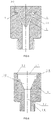
FIGS. 1 and 2 are structural schematic views showing a specific embodiment of the device utilizing air for tempered glass cooling according to the present invention, whereinFIG. 1 is a front view (only the air ducts and the glass to be processed are shown) andFIG. 2 is a bottom view (the air ducts and the compressed air supply unit are shown). -
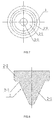
FIGS. 3 to 5 are structural schematic views showing an air nozzle according to a specific embodiment of the device utilizing air for tempered glass cooling of the present invention, whereinFIG. 3 is a front view (sectional view),FIG. 4 is a top view andFIG. 5 is an A-A sectional view ofFIG. 3 . -
FIGS. 6 and7 are structural schematic views of the housing body shown inFIG. 3 , whereinFIG. 6 is a front view (sectional view) andFIG. 7 is a top view. -
FIGS. 8 to 10 are structural schematic views of the embedded body shown inFIG. 3 , whereinFIG. 8 is a front view (sectional view),FIG. 9 is a left view andFIG. 10 is a top view. -
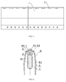
FIGS. 11 to 13 are structural schematic views showing implementation of the air ducts according to a specific embodiment of the device utilizing air for tempered glass cooling of the present invention, whereinFIG. 11 is a front view,FIG. 12 is a left view (sectional view) andFIG. 13 is a top view. -
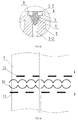
FIG. 14 is an enlarged view of the "I" region inFIG. 12 . -
FIG. 15 is a structural schematic view after the structure shown inFIG. 14 is mounted with the embedded body. -
FIG. 16 is a schematic view of the wind bands formed on the glass by the air ducts. - The present invention will be further described in detail below in conjunction with the accompanying drawings and embodiments, but the implementation of the present invention is not limited thereto.
- With reference to
FIGS. 1 and 2 , the device utilizing air for tempered glass cooling of the present invention comprises a compressed air supply unit,air ducts 12 connecting to the compressed air supply unit, andair nozzles 15 located on theair ducts 12. - With reference to
FIGS. 3 to 9 , each of theair nozzles 15 comprises ahousing body 1 and an embeddedbody 2 located in thehousing body 1, wherein an inner cavity 1-1 for mounting the embeddedbody 2 is provided inside thehousing body 1, a taperedair guiding passage 3 gradually widening outward is formed between an external wall of the embeddedbody 2 and the inner cavity 1-1 surface. Two arc-shapedair outlets 4 opposing each other are formed at a distal end of the taperedair guiding passage 3. A partition is arranged between opposing ends of the two arc-shapedair outlets 4 for separating the two arc-shapedair outlets 4. - With reference to
FIGS. 3 to 9 , the inner cavity 1-1 of thehousing body 1 is formed by an air inlet section 1-3, an air guiding section 1-2 and an air outlet section 1-4 sequentially connected to one another, wherein a cross section of the air inlet section 1-3 is circular. The air guiding section 1-2 is tapered. A cross section of the air outlet section 1-4 is also circular. The radial dimension of the air outlet section 1-4 is bigger than the longest diameter of the air guiding section 1-2; connection threads 1-6 are provided at one end of thehousing body 1 corresponding to the air inlet section 1-3, the connection threads 1-6 are used for connecting theair nozzle 15 onto a respective air duct 23. The embeddedbody 2 is formed by connecting a tapered body 2-1 and a separating body 2-2, wherein the tapered body 2-1 matches with and fitted inside the air guiding section 1-2. A space between the external wall of the tapered body 2-1 and the air guiding section 1-2 surface forms the taperedair guiding passage 3. The separating body 2-2 matches with and fitted within the air outlet section 1-4. The separating body 2-2 spans across a top surface of the tapered body 2-1. The outer side surfaces of the separating body 2-2 are circular arc surfaces which matches with the wall surface of the air outlet section 1-4, and a bottom surface of the separating body 2-2 is attached to a bottom surface of the air outlet section 1-4; by matching the separating body 2-2 and the air outlet section 1-4, a positioning function is achieved, so that the embeddedbody 2 simply needs to be mounted into the inner cavity 1-1 of thehousing body 1, and then the taperedair guiding passage 3 can be formed; also, the separating body 2-2 forms the partition, thereby separating the exit of the taperedair guiding passage 3 into two arc-shapedair outlets 4, so that this separating body 2-2 does not only serve a positioning function but also a separating function. In order not to block the flow of airstreams flowing out from the arc-shapedair outlets 4, an edge of a top part of the air outlet section 1-4 is provided with a chamfer 1-5. - With reference to
FIGS. 3 to 5 , the taperedair guiding passage 3 has the same cross sectional area in any of its cross sections. The purpose is to ensure the stability of air volume and air pressure everywhere within the taperedair guiding passage 3, thereby ensuring that the air volume and air pressure blowing from the arc-shapedair outlets 4 are even. To attain this purpose, the taper shape of the air guiding section 1-2 and the taper shape of the tapered body 2-1 are different, wherein the width of the taperedair guiding passage 3 at the end corresponding to the tip of the tapered body 2-1 is wider. The width at another end is narrower. The middle section is a gradational transition between the wider width at said end and the narrower end at said another end. Thus, it is ensured that the taperedair guiding passage 3 has the same cross sectional area in any of its cross sections; specifically, the taper of the air guiding section 1-2 is 47 degrees; the taper of the tapered body 2-1 is 50 degrees. - With reference to
FIGS. 3 to 5 andFIGS 8 to 10 , the tapered body 2-1 is provided with a cylindrical section 2-3 in the part connecting with the separating body 2-2. The cylindrical section 2-3 is provided so that the dimension of the largest diameter section of the cylindrical section 2-3 can be measured. To ensure that the taperedair guiding passage 3 has the same cross sectional area at any of its cross sections, it is necessary to determine the dimension of the largest diameter section of the cylindrical section 2-3. Without the cylindrical section 2-3, it is not easy to measure. Usually the length of this cylindrical section 2-3 is set to be about 0.3mm. Since this length is small, it has no impact on wind direction. - With reference to
FIGS. 3 to 5 , the tip of the tapered body 2-1 projects into the air inlet section 1-3; this tip of the tapered body 2-1 is made into a round head; a center of this tip coincides with a center line of the air inlet section 1-3. This allows the air entering the air inlet section 1-3 to be evenly distributed to the taperedair guiding passage 3, ensuring the stability of air volume and air pressure everywhere within the taperedair guiding passage 3. - With reference to
FIGS. 1, 2 andFIGS. 11 to 15 , each of theair ducts 12 comprises a high-pressure air duct 5 located at an inner side and a low-pressure air duct 6 located at an outer side. A center of an air-outflow end face of eachair duct 12 is provided with a plurality of saidair nozzles 15 arranged along a longitudinal direction of theair duct 12. The air nozzles 15 is in communication with an internal passage 5-1 of the high-pressure air duct 5. The two arc-shapedair outlets 4 of eachair nozzle 15 are arranged along a direction that is perpendicular to the longitudinal direction of theair duct 12; both sides of theair nozzle 15 are respectively provided with a plurality of air exits 6-2 arranged along the longitudinal direction of theair duct 12, the air exits 6-2 are in communication with the internal passage 6-1 of the low-pressure air duct 6. The compressed air supply unit comprises a high-pressureair supply device 13 and a low-pressureair supply device 14, wherein the high-pressureair supply device 13 is connected to the internal passage 5-1 of each high-pressure air duct 5 through air supply lines. The high-pressureair supply device 13 comprises components such as an air compressor, an air storage tank, an air purification can and pipe lines, the high-pressureair supply device 13 is used for supplying high-pressure air into each high-pressure air duct 5. The high-pressure air enters the internal passage 5-1 of each high-pressure air duct 5 from both ends of acorresponding air duct 12; the low-pressureair supply device 14 is connected to the internal passage 6-1 of each low-pressure air duct 6 through air supply lines. The low-pressureair supply device 14 comprises components such as an air blower, an air box, an air purification can and pipe lines, the low-pressureair supply device 14 is used for supplying low-pressure air to each low-pressure air duct 6. The low-pressure air enters the internal passage 6-1 of each low-pressure air duct 6 from one end of acorresponding air duct 12. The high-pressure air in the above-mentioned high-pressure air duct 5 has great pressure but small volume when blowing out from theair nozzles 15; the low-pressure air in the low-pressure air duct 6 has small pressure but high volume when blowing out from the air exits 6-2. To achieve a better cooling effect, it is necessary to ensure that the air pressure and air volume are large at the same time when cooling the tempered glass. With the use of theair duct 12 formed by the high-pressure air duct 5 and the low-pressure air duct 6, the above-mentioned requirements can be satisfied. - With reference to
FIGS. 1, 2 and14 , the device utilizing air for tempered glass cooling comprises a plurality ofair ducts 12. Theseair ducts 12 are arranged along the movement direction of the tamperedglass 9. During operation, the temperedglass 9 is subject to a large amount of high-pressure air sending out from theair nozzles 15 and the low-pressure air sending out from the air exits 6-2 to achieve cooling effect. - With reference to
FIGS. 12 to 15 , the high-pressure air duct 5 and the low-pressure air duct 6 connect with each other at a side wall corresponding to the air-outflow end face. A middle of this air-outflow end face is ahorizontal section 7. The air nozzles 15 are provided on thishorizontal section 7; the two sides of the middle of this air-outflow end face are slopingsections 8 respectively, the air exits 6-2 are provided on the slopingsections 8. Thehousing body 1 in theair nozzle 15 is partially formed as a one whole piece with the air-outflow end face of the high-pressure air duct 5. In other words, the inner cavity 1-1 of theair nozzle 15 is provided within a wall body of the high-pressure air duct 5 corresponding to the air-outflow end face. The inner cavity 1-1 of theair nozzle 15 communicates with the internal passage 5-1 of the high-pressure air duct 5. The high-pressure air duct 5 and the low-pressure air duct 6 are made by extrusion process. The inner cavity 1-1 is obtained by a numerical control process. Theair nozzle 15 configured as above can eliminate the procedures of manufacturing anindependent housing body 1 and assembling thehousing body 1, thereby saving costs. - With reference to
FIGS. 14 and15 , along an air-outflow direction, a shape that the two arc-shapedair outlets 4 of eachair nozzle 15 project onto aglass 9 surface is in a bracket shape (i.e. " () " shape); a plurality of " () " shapes projected by a plurality ofair nozzles 15 are connected in sequence, achievable by setting the distance between theair nozzles 15 and the taper of the taperedair guiding section 3. The air exits 6-2 are located on both sides of theair nozzles 15. The air-outflow direction of one row of air exits 6-2 forms an included angle of about about 45° with the air-outflow direction of another row of air exits 6-2. The projections of the shapes of the two rows of air exits 6-2 on theglass 9 surface are located on both sides of the " ( ) " shape projection respectively. In theair duct 12 of the present invention, high-pressure air blows out from theair nozzles 15 at the middle of the air-outflow end face, and low-pressure air blows out from the air exits 6-2 at both sides of the middle of the air-outflow end face. The two types of cooling air can be mixed together or used separately. - The working principle of the device utilizing air for tempered glass cooling according to the present invention is as follows:
- With reference to
FIGS. 1, 2 and15 , during operation,many air ducts 12 span across the top of theglass 9 along a width direction of theglass 9. The high-pressureair supply device 13 supplies high-pressure air into the internal passage 5-1 of each high-pressure air duct 5 through air supply lines. The low-pressureair supply device 14 supplies low-pressure air into the internal passage 6-1 of each low-pressure air duct 6 through air supply lines; wherein the high-pressure air is blown out from eachair nozzle 15. Guided by the taperedair guiding passage 3 of eachair nozzle 15, the compressed air flows forward in a gradual widening angle, and is then divided into two streams discharging out from the two arc-shapedair outlets 4 respectively under the separation of the partition, forming two arc-shaped wind bands with uniform pressure and uniform speed that hit against the glass to be rapidly cooled so as to perform uniform cooling of the glass surface. In eachair duct 12, the high-pressure air blown out from theair nozzles 15 forms acontinuous wind band 10 of high-pressure cooling air; low-pressure air is blown out from the air exits; the low-pressure air blown out from the air exits 6-2 in eachair duct 12 forms twowind bands 11 of low-pressure cooling air located at both sides of thewind band 10 of high-pressure cooling air on the glass surface. Theglass 9 at high temperature moves back and forth below theair ducts 12 for rapid cooling by the above-mentionedwind band 10 of high-pressure cooling air andwind bands 11 of low-pressure cooling air. - The above examples are preferred embodiments of the present invention. However, the implementation of the present invention are not restricted by the above examples, and any other modification, amendment, replacement, combination and simplification not departing from the spirit and principle of the present invention shall be the equivalent alternatives, and all fall within the scope of protection of the present invention.
Claims (10)
- A device utilizing air for tempered glass cooling, comprising a compressed air supply unit, air ducts (12) which connect with the compressed air supply unit, and air nozzles (15) located on the air ducts (12), characterized in that:each of the air nozzles (15) comprises a housing body (1) and an embedded body (2) located in the housing body (1), wherein an interior side of the housing body (1) is provided with an inner cavity (1-1) for mounting the embedded body (2), a tapered air guiding passage (3) gradually widening outward is formed between an external wall of the embedded body (2) and an inner cavity surface; a distal end of the tapered air guiding passage (3) forms two arc-shaped air outlets (4) opposing each other; a partition is arranged between opposite ends of the two arc-shaped air outlets (4) for separating the two arc-shaped air outlets.
- The device utilizing air for tempered glass cooling as in claim 1, wherein the inner cavity (1-1) of the housing body (1) is formed by an air inlet section (1-3), an air guiding section (1-2) and an air outlet section (1-4) connected in sequence; the embedded body (2) is formed by connecting a tapered body (2-1) and a separating body (2-2), wherein the tapered body (2-1) matches with and fits inside the air guiding section (1-2); a space between an external wall of the tapered body (2-1) and an air guiding section surface forms the tapered air guiding passage (3); a radial dimension of the air outlet section (1-4) is bigger than the largest diameter of the air guiding section (1-2); the separating body (2-2) matches with and fits on a top part of the air outlet section (1-4); the separating body (2-2) forms the partition.
- The device utilizing air for tempered glass cooling as in claim 2, wherein a cross section of the air outlet section (1-4) has a circular shape; outer side surfaces of the separating body (2-2) are circular arc surfaces which match with the circular cross section of the air outlet section (1-4).
- The device utilizing air for tempered glass cooling as in claim 2, wherein the tapered air guiding passage (3) has a same cross sectional area at any of its cross sections.
- The device utilizing air for tempered glass cooling as in claim 4, wherein a taper of the air guiding section (1-2) is 30-120 degrees; a taper of the tapered body (2-1) is 35-150 degrees.
- The device utilizing air for tempered glass cooling as in claim 2, wherein a cross section of the air inlet section (1-3) is in a circular shape; a tip of the tapered body (2-1) projects into the air inlet section (1-3); the tip of the tapered body (2-1) is made into a round head; a center of the tip coincides with a center line of the air inlet section (1-3).
- The device utilizing air for tempered glass cooling as in any one of claims 1-6, wherein each of the air ducts (12) comprises a high-pressure air duct (5) located at an inner side and a low-pressure air duct (6) located at an outer side; a center of an air-outflow end face of each air duct (12) is provided with a plurality of said air nozzles (15) arranged along a longitudinal direction of the air duct (12); the air nozzles (15) are in communication with an internal passage (5-1) of the high-pressure air duct (5); the two arc-shaped air outlets (4) of each air nozzle (15) are arranged along a direction that is perpendicular to the longitudinal direction of the air duct (12); both sides of the air nozzle (15) are respectively provided with a plurality of air exits (6-2) arranged along the longitudinal direction of the air duct, the air exits (6-2) are in communication with an internal passage (6-1) of the low-pressure air duct (6);
the compressed air supply unit comprises a high-pressure air supply device (13) and a low-pressure air supply device (14), wherein the high-pressure air supply device (13) is connected to the internal passage (5-1) of each high-pressure air duct (5) through air supply lines, and the low-pressure air supply device (14) is connected to the internal passage (6-1) of each low-pressure air duct (6) through air supply lines. - The device utilizing air for tempered glass cooling as in claim 7, wherein the housing body in the air nozzle (15) is formed as a one whole piece with the high-pressure air duct (5); an inner cavity of the air nozzle (15) communicates with the internal passage (5-1) of the high-pressure air duct (5).
- The device utilizing air for tempered glass cooling as in claim 7, wherein a shape that the two arc-shaped air outlets (4) of each air nozzle (15) project onto a glass surface along an air-outflow direction is in a " ( ) " shape; a plurality of " () " shapes projected by a plurality of air nozzles (15) are connected in sequence.
- The device utilizing air for tempered glass cooling as in claim 7, wherein the high-pressure air duct (5) and the low-pressure air duct (6) connect with each other at a side wall corresponding to the air-outflow end face; a middle of the air-outflow end face is a horizontal section (7); the air nozzles (15) are provided on the horizontal section (7); two sides of the middle of the air-outflow end face are sloping sections (8) respectively, the air exits (6-2) are provided on the sloping sections (8).
Priority Applications (1)
| Application Number | Priority Date | Filing Date | Title |
|---|---|---|---|
| EP16152099.4A EP3196172B1 (en) | 2016-01-20 | 2016-01-20 | Device using cooling air for tempering glass |
Applications Claiming Priority (1)
| Application Number | Priority Date | Filing Date | Title |
|---|---|---|---|
| EP16152099.4A EP3196172B1 (en) | 2016-01-20 | 2016-01-20 | Device using cooling air for tempering glass |
Publications (2)
| Publication Number | Publication Date |
|---|---|
| EP3196172A1 true EP3196172A1 (en) | 2017-07-26 |
| EP3196172B1 EP3196172B1 (en) | 2018-10-17 |
Family
ID=55177872
Family Applications (1)
| Application Number | Title | Priority Date | Filing Date |
|---|---|---|---|
| EP16152099.4A Active EP3196172B1 (en) | 2016-01-20 | 2016-01-20 | Device using cooling air for tempering glass |
Country Status (1)
| Country | Link |
|---|---|
| EP (1) | EP3196172B1 (en) |
Cited By (3)
| Publication number | Priority date | Publication date | Assignee | Title |
|---|---|---|---|---|
| CN109133595A (en) * | 2018-10-13 | 2019-01-04 | 中航三鑫太阳能光电玻璃有限公司 | A kind of cold reinforcing device of thin glass wind quenching |
| CN114735929A (en) * | 2022-05-23 | 2022-07-12 | 秦皇岛市运通玻璃机电技术有限公司 | Toughened glass bending device and production system |
| US11702357B2 (en) * | 2016-07-21 | 2023-07-18 | Saint-Gobain Glass France | Nozzle strip for a blow box for thermally prestressing glass panes |
Families Citing this family (1)
| Publication number | Priority date | Publication date | Assignee | Title |
|---|---|---|---|---|
| FI129685B (en) * | 2020-06-08 | 2022-06-30 | Glaston Finland Oy | Method and device for tempering glass sheets |
Citations (6)
| Publication number | Priority date | Publication date | Assignee | Title |
|---|---|---|---|---|
| US3293015A (en) * | 1961-09-22 | 1966-12-20 | Pittsburgh Plate Glass Co | Method and apparatus for tempering glass sheets on a gas support bed |
| EP0558912A1 (en) * | 1992-02-12 | 1993-09-08 | Tamglass Engineering Oy | Nozzle assembly for a flat-glass tempering machine |
| EP0968970A2 (en) * | 1998-06-30 | 2000-01-05 | Tamglass Ltd. Oy | Method and apparatus for tempering glass panels |
| CN2608497Y (en) | 2003-03-26 | 2004-03-31 | 许涛 | Slot type air grid nozzle |
| CN103992027A (en) * | 2014-06-04 | 2014-08-20 | 佛山市索奥斯玻璃技术有限公司 | Tempered glass air-cooled tuyere and air hose comprising same |
| CN203960044U (en) * | 2014-06-04 | 2014-11-26 | 佛山市索奥斯玻璃技术有限公司 | The air-cooled tuyere of a kind of toughened glass and the airduct that comprises this tuyere |
-
2016
- 2016-01-20 EP EP16152099.4A patent/EP3196172B1/en active Active
Patent Citations (6)
| Publication number | Priority date | Publication date | Assignee | Title |
|---|---|---|---|---|
| US3293015A (en) * | 1961-09-22 | 1966-12-20 | Pittsburgh Plate Glass Co | Method and apparatus for tempering glass sheets on a gas support bed |
| EP0558912A1 (en) * | 1992-02-12 | 1993-09-08 | Tamglass Engineering Oy | Nozzle assembly for a flat-glass tempering machine |
| EP0968970A2 (en) * | 1998-06-30 | 2000-01-05 | Tamglass Ltd. Oy | Method and apparatus for tempering glass panels |
| CN2608497Y (en) | 2003-03-26 | 2004-03-31 | 许涛 | Slot type air grid nozzle |
| CN103992027A (en) * | 2014-06-04 | 2014-08-20 | 佛山市索奥斯玻璃技术有限公司 | Tempered glass air-cooled tuyere and air hose comprising same |
| CN203960044U (en) * | 2014-06-04 | 2014-11-26 | 佛山市索奥斯玻璃技术有限公司 | The air-cooled tuyere of a kind of toughened glass and the airduct that comprises this tuyere |
Cited By (3)
| Publication number | Priority date | Publication date | Assignee | Title |
|---|---|---|---|---|
| US11702357B2 (en) * | 2016-07-21 | 2023-07-18 | Saint-Gobain Glass France | Nozzle strip for a blow box for thermally prestressing glass panes |
| CN109133595A (en) * | 2018-10-13 | 2019-01-04 | 中航三鑫太阳能光电玻璃有限公司 | A kind of cold reinforcing device of thin glass wind quenching |
| CN114735929A (en) * | 2022-05-23 | 2022-07-12 | 秦皇岛市运通玻璃机电技术有限公司 | Toughened glass bending device and production system |
Also Published As
| Publication number | Publication date |
|---|---|
| EP3196172B1 (en) | 2018-10-17 |
Similar Documents
| Publication | Publication Date | Title |
|---|---|---|
| EP3196172B1 (en) | Device using cooling air for tempering glass | |
| CN103306744B (en) | Cooling device for guide vane | |
| ITMI20100249U1 (en) | HEAT EXCHANGE DEVICE WITH REFRIGERANT FLUID DISTRIBUTION SYSTEM | |
| CN102917803A (en) | Nozzle head for a spray device | |
| BR0204695B1 (en) | Air-assisted spray nozzle and spray system for directing a coolant in a metal smelter | |
| CA2521088A1 (en) | Apparatus and method for forming fibers | |
| CN104624424A (en) | Aerosol cooling device for cooling strip steel | |
| CN106640216A (en) | Air film cooling hole structure | |
| CN104923582B (en) | A kind of aluminium section bar cooling duct | |
| CN208292866U (en) | Wire-drawing shape device for glass fiber direct roving | |
| JP2018536112A (en) | Injection hole disk and valve | |
| CN211437494U (en) | Rapid cooling device for high-speed wire | |
| CN104019650A (en) | Drying air cutter for glass cleaning machine | |
| EP3513661B1 (en) | Elongated funnel-shaped jet nozzle structure | |
| CN203960044U (en) | The air-cooled tuyere of a kind of toughened glass and the airduct that comprises this tuyere | |
| CN107588579A (en) | Evaporator and air conditioning system | |
| CN111715708B (en) | Uniform cooling device and cooling method for wire rod after spinning and coiling | |
| CN103992027A (en) | Tempered glass air-cooled tuyere and air hose comprising same | |
| ES2310393T3 (en) | SPRAY HEAD. | |
| CN206329360U (en) | A kind of pass structure of raising downstream cooling effect | |
| CN214457617U (en) | Glass tempering quenching device cooled by mixed gas | |
| CN203816808U (en) | Nozzle of spray gun | |
| CN106440036A (en) | Indoor unit of air conditioner and air conditioner | |
| CN202415632U (en) | Steam fog cooling device for heat treatment | |
| CN106440034B (en) | Air conditioner indoor unit and air conditioner |
Legal Events
| Date | Code | Title | Description |
|---|---|---|---|
| PUAI | Public reference made under article 153(3) epc to a published international application that has entered the european phase |
Free format text: ORIGINAL CODE: 0009012 |
|
| STAA | Information on the status of an ep patent application or granted ep patent |
Free format text: STATUS: REQUEST FOR EXAMINATION WAS MADE |
|
| 17P | Request for examination filed |
Effective date: 20160329 |
|
| AK | Designated contracting states |
Kind code of ref document: A1 Designated state(s): AL AT BE BG CH CY CZ DE DK EE ES FI FR GB GR HR HU IE IS IT LI LT LU LV MC MK MT NL NO PL PT RO RS SE SI SK SM TR |
|
| AX | Request for extension of the european patent |
Extension state: BA ME |
|
| RIN1 | Information on inventor provided before grant (corrected) |
Inventor name: ZHOU, JUNSHAN |
|
| GRAP | Despatch of communication of intention to grant a patent |
Free format text: ORIGINAL CODE: EPIDOSNIGR1 |
|
| STAA | Information on the status of an ep patent application or granted ep patent |
Free format text: STATUS: GRANT OF PATENT IS INTENDED |
|
| INTG | Intention to grant announced |
Effective date: 20180709 |
|
| GRAS | Grant fee paid |
Free format text: ORIGINAL CODE: EPIDOSNIGR3 |
|
| GRAA | (expected) grant |
Free format text: ORIGINAL CODE: 0009210 |
|
| STAA | Information on the status of an ep patent application or granted ep patent |
Free format text: STATUS: THE PATENT HAS BEEN GRANTED |
|
| AK | Designated contracting states |
Kind code of ref document: B1 Designated state(s): AL AT BE BG CH CY CZ DE DK EE ES FI FR GB GR HR HU IE IS IT LI LT LU LV MC MK MT NL NO PL PT RO RS SE SI SK SM TR |
|
| REG | Reference to a national code |
Ref country code: GB Ref legal event code: FG4D |
|
| REG | Reference to a national code |
Ref country code: CH Ref legal event code: EP |
|
| REG | Reference to a national code |
Ref country code: IE Ref legal event code: FG4D |
|
| REG | Reference to a national code |
Ref country code: DE Ref legal event code: R096 Ref document number: 602016006337 Country of ref document: DE Ref country code: AT Ref legal event code: REF Ref document number: 1053798 Country of ref document: AT Kind code of ref document: T Effective date: 20181115 |
|
| REG | Reference to a national code |
Ref country code: NL Ref legal event code: MP Effective date: 20181017 |
|
| REG | Reference to a national code |
Ref country code: LT Ref legal event code: MG4D |
|
| REG | Reference to a national code |
Ref country code: AT Ref legal event code: MK05 Ref document number: 1053798 Country of ref document: AT Kind code of ref document: T Effective date: 20181017 |
|
| PG25 | Lapsed in a contracting state [announced via postgrant information from national office to epo] |
Ref country code: NL Free format text: LAPSE BECAUSE OF FAILURE TO SUBMIT A TRANSLATION OF THE DESCRIPTION OR TO PAY THE FEE WITHIN THE PRESCRIBED TIME-LIMIT Effective date: 20181017 |
|
| PGFP | Annual fee paid to national office [announced via postgrant information from national office to epo] |
Ref country code: LU Payment date: 20190122 Year of fee payment: 4 |
|
| PG25 | Lapsed in a contracting state [announced via postgrant information from national office to epo] |
Ref country code: FI Free format text: LAPSE BECAUSE OF FAILURE TO SUBMIT A TRANSLATION OF THE DESCRIPTION OR TO PAY THE FEE WITHIN THE PRESCRIBED TIME-LIMIT Effective date: 20181017 Ref country code: LV Free format text: LAPSE BECAUSE OF FAILURE TO SUBMIT A TRANSLATION OF THE DESCRIPTION OR TO PAY THE FEE WITHIN THE PRESCRIBED TIME-LIMIT Effective date: 20181017 Ref country code: HR Free format text: LAPSE BECAUSE OF FAILURE TO SUBMIT A TRANSLATION OF THE DESCRIPTION OR TO PAY THE FEE WITHIN THE PRESCRIBED TIME-LIMIT Effective date: 20181017 Ref country code: PL Free format text: LAPSE BECAUSE OF FAILURE TO SUBMIT A TRANSLATION OF THE DESCRIPTION OR TO PAY THE FEE WITHIN THE PRESCRIBED TIME-LIMIT Effective date: 20181017 Ref country code: AT Free format text: LAPSE BECAUSE OF FAILURE TO SUBMIT A TRANSLATION OF THE DESCRIPTION OR TO PAY THE FEE WITHIN THE PRESCRIBED TIME-LIMIT Effective date: 20181017 Ref country code: BG Free format text: LAPSE BECAUSE OF FAILURE TO SUBMIT A TRANSLATION OF THE DESCRIPTION OR TO PAY THE FEE WITHIN THE PRESCRIBED TIME-LIMIT Effective date: 20190117 Ref country code: NO Free format text: LAPSE BECAUSE OF FAILURE TO SUBMIT A TRANSLATION OF THE DESCRIPTION OR TO PAY THE FEE WITHIN THE PRESCRIBED TIME-LIMIT Effective date: 20190117 Ref country code: IS Free format text: LAPSE BECAUSE OF FAILURE TO SUBMIT A TRANSLATION OF THE DESCRIPTION OR TO PAY THE FEE WITHIN THE PRESCRIBED TIME-LIMIT Effective date: 20190217 Ref country code: LT Free format text: LAPSE BECAUSE OF FAILURE TO SUBMIT A TRANSLATION OF THE DESCRIPTION OR TO PAY THE FEE WITHIN THE PRESCRIBED TIME-LIMIT Effective date: 20181017 Ref country code: ES Free format text: LAPSE BECAUSE OF FAILURE TO SUBMIT A TRANSLATION OF THE DESCRIPTION OR TO PAY THE FEE WITHIN THE PRESCRIBED TIME-LIMIT Effective date: 20181017 |
|
| PGFP | Annual fee paid to national office [announced via postgrant information from national office to epo] |
Ref country code: NL Payment date: 20190121 Year of fee payment: 4 Ref country code: IE Payment date: 20190122 Year of fee payment: 4 |
|
| PG25 | Lapsed in a contracting state [announced via postgrant information from national office to epo] |
Ref country code: PT Free format text: LAPSE BECAUSE OF FAILURE TO SUBMIT A TRANSLATION OF THE DESCRIPTION OR TO PAY THE FEE WITHIN THE PRESCRIBED TIME-LIMIT Effective date: 20190217 Ref country code: GR Free format text: LAPSE BECAUSE OF FAILURE TO SUBMIT A TRANSLATION OF THE DESCRIPTION OR TO PAY THE FEE WITHIN THE PRESCRIBED TIME-LIMIT Effective date: 20190118 Ref country code: RS Free format text: LAPSE BECAUSE OF FAILURE TO SUBMIT A TRANSLATION OF THE DESCRIPTION OR TO PAY THE FEE WITHIN THE PRESCRIBED TIME-LIMIT Effective date: 20181017 Ref country code: SE Free format text: LAPSE BECAUSE OF FAILURE TO SUBMIT A TRANSLATION OF THE DESCRIPTION OR TO PAY THE FEE WITHIN THE PRESCRIBED TIME-LIMIT Effective date: 20181017 Ref country code: AL Free format text: LAPSE BECAUSE OF FAILURE TO SUBMIT A TRANSLATION OF THE DESCRIPTION OR TO PAY THE FEE WITHIN THE PRESCRIBED TIME-LIMIT Effective date: 20181017 |
|
| REG | Reference to a national code |
Ref country code: DE Ref legal event code: R097 Ref document number: 602016006337 Country of ref document: DE |
|
| PG25 | Lapsed in a contracting state [announced via postgrant information from national office to epo] |
Ref country code: IT Free format text: LAPSE BECAUSE OF FAILURE TO SUBMIT A TRANSLATION OF THE DESCRIPTION OR TO PAY THE FEE WITHIN THE PRESCRIBED TIME-LIMIT Effective date: 20181017 Ref country code: CZ Free format text: LAPSE BECAUSE OF FAILURE TO SUBMIT A TRANSLATION OF THE DESCRIPTION OR TO PAY THE FEE WITHIN THE PRESCRIBED TIME-LIMIT Effective date: 20181017 Ref country code: DK Free format text: LAPSE BECAUSE OF FAILURE TO SUBMIT A TRANSLATION OF THE DESCRIPTION OR TO PAY THE FEE WITHIN THE PRESCRIBED TIME-LIMIT Effective date: 20181017 |
|
| PLBE | No opposition filed within time limit |
Free format text: ORIGINAL CODE: 0009261 |
|
| STAA | Information on the status of an ep patent application or granted ep patent |
Free format text: STATUS: NO OPPOSITION FILED WITHIN TIME LIMIT |
|
| PG25 | Lapsed in a contracting state [announced via postgrant information from national office to epo] |
Ref country code: SM Free format text: LAPSE BECAUSE OF FAILURE TO SUBMIT A TRANSLATION OF THE DESCRIPTION OR TO PAY THE FEE WITHIN THE PRESCRIBED TIME-LIMIT Effective date: 20181017 Ref country code: EE Free format text: LAPSE BECAUSE OF FAILURE TO SUBMIT A TRANSLATION OF THE DESCRIPTION OR TO PAY THE FEE WITHIN THE PRESCRIBED TIME-LIMIT Effective date: 20181017 Ref country code: SK Free format text: LAPSE BECAUSE OF FAILURE TO SUBMIT A TRANSLATION OF THE DESCRIPTION OR TO PAY THE FEE WITHIN THE PRESCRIBED TIME-LIMIT Effective date: 20181017 Ref country code: RO Free format text: LAPSE BECAUSE OF FAILURE TO SUBMIT A TRANSLATION OF THE DESCRIPTION OR TO PAY THE FEE WITHIN THE PRESCRIBED TIME-LIMIT Effective date: 20181017 |
|
| 26N | No opposition filed |
Effective date: 20190718 |
|
| REG | Reference to a national code |
Ref country code: BE Ref legal event code: MM Effective date: 20190131 |
|
| PG25 | Lapsed in a contracting state [announced via postgrant information from national office to epo] |
Ref country code: SI Free format text: LAPSE BECAUSE OF FAILURE TO SUBMIT A TRANSLATION OF THE DESCRIPTION OR TO PAY THE FEE WITHIN THE PRESCRIBED TIME-LIMIT Effective date: 20181017 |
|
| PG25 | Lapsed in a contracting state [announced via postgrant information from national office to epo] |
Ref country code: BE Free format text: LAPSE BECAUSE OF NON-PAYMENT OF DUE FEES Effective date: 20190131 |
|
| PG25 | Lapsed in a contracting state [announced via postgrant information from national office to epo] |
Ref country code: TR Free format text: LAPSE BECAUSE OF FAILURE TO SUBMIT A TRANSLATION OF THE DESCRIPTION OR TO PAY THE FEE WITHIN THE PRESCRIBED TIME-LIMIT Effective date: 20181017 |
|
| PG25 | Lapsed in a contracting state [announced via postgrant information from national office to epo] |
Ref country code: MT Free format text: LAPSE BECAUSE OF NON-PAYMENT OF DUE FEES Effective date: 20190120 |
|
| PG25 | Lapsed in a contracting state [announced via postgrant information from national office to epo] |
Ref country code: MC Free format text: LAPSE BECAUSE OF NON-PAYMENT OF DUE FEES Effective date: 20200131 |
|
| PG25 | Lapsed in a contracting state [announced via postgrant information from national office to epo] |
Ref country code: LU Free format text: LAPSE BECAUSE OF NON-PAYMENT OF DUE FEES Effective date: 20200120 |
|
| PG25 | Lapsed in a contracting state [announced via postgrant information from national office to epo] |
Ref country code: IE Free format text: LAPSE BECAUSE OF NON-PAYMENT OF DUE FEES Effective date: 20200120 |
|
| PG25 | Lapsed in a contracting state [announced via postgrant information from national office to epo] |
Ref country code: CY Free format text: LAPSE BECAUSE OF FAILURE TO SUBMIT A TRANSLATION OF THE DESCRIPTION OR TO PAY THE FEE WITHIN THE PRESCRIBED TIME-LIMIT Effective date: 20181017 |
|
| PG25 | Lapsed in a contracting state [announced via postgrant information from national office to epo] |
Ref country code: HU Free format text: LAPSE BECAUSE OF FAILURE TO SUBMIT A TRANSLATION OF THE DESCRIPTION OR TO PAY THE FEE WITHIN THE PRESCRIBED TIME-LIMIT; INVALID AB INITIO Effective date: 20160120 |
|
| PG25 | Lapsed in a contracting state [announced via postgrant information from national office to epo] |
Ref country code: MK Free format text: LAPSE BECAUSE OF FAILURE TO SUBMIT A TRANSLATION OF THE DESCRIPTION OR TO PAY THE FEE WITHIN THE PRESCRIBED TIME-LIMIT Effective date: 20181017 |
|
| PGFP | Annual fee paid to national office [announced via postgrant information from national office to epo] |
Ref country code: GB Payment date: 20231221 Year of fee payment: 9 |
|
| PGFP | Annual fee paid to national office [announced via postgrant information from national office to epo] |
Ref country code: DE Payment date: 20240119 Year of fee payment: 9 Ref country code: CH Payment date: 20240202 Year of fee payment: 9 |
|
| PGFP | Annual fee paid to national office [announced via postgrant information from national office to epo] |
Ref country code: FR Payment date: 20240124 Year of fee payment: 9 |