EP3196067A1 - Fluid heating device of engine - Google Patents
Fluid heating device of engine Download PDFInfo
- Publication number
- EP3196067A1 EP3196067A1 EP16199038.7A EP16199038A EP3196067A1 EP 3196067 A1 EP3196067 A1 EP 3196067A1 EP 16199038 A EP16199038 A EP 16199038A EP 3196067 A1 EP3196067 A1 EP 3196067A1
- Authority
- EP
- European Patent Office
- Prior art keywords
- holder
- pipe
- heat radiation
- coil
- heating device
- Prior art date
- Legal status (The legal status is an assumption and is not a legal conclusion. Google has not performed a legal analysis and makes no representation as to the accuracy of the status listed.)
- Granted
Links
Images




Classifications
-
- F—MECHANICAL ENGINEERING; LIGHTING; HEATING; WEAPONS; BLASTING
- F01—MACHINES OR ENGINES IN GENERAL; ENGINE PLANTS IN GENERAL; STEAM ENGINES
- F01M—LUBRICATING OF MACHINES OR ENGINES IN GENERAL; LUBRICATING INTERNAL COMBUSTION ENGINES; CRANKCASE VENTILATING
- F01M13/00—Crankcase ventilating or breathing
-
- H—ELECTRICITY
- H05—ELECTRIC TECHNIQUES NOT OTHERWISE PROVIDED FOR
- H05B—ELECTRIC HEATING; ELECTRIC LIGHT SOURCES NOT OTHERWISE PROVIDED FOR; CIRCUIT ARRANGEMENTS FOR ELECTRIC LIGHT SOURCES, IN GENERAL
- H05B6/00—Heating by electric, magnetic or electromagnetic fields
- H05B6/02—Induction heating
- H05B6/10—Induction heating apparatus, other than furnaces, for specific applications
- H05B6/105—Induction heating apparatus, other than furnaces, for specific applications using a susceptor
- H05B6/108—Induction heating apparatus, other than furnaces, for specific applications using a susceptor for heating a fluid
-
- B—PERFORMING OPERATIONS; TRANSPORTING
- B60—VEHICLES IN GENERAL
- B60H—ARRANGEMENTS OF HEATING, COOLING, VENTILATING OR OTHER AIR-TREATING DEVICES SPECIALLY ADAPTED FOR PASSENGER OR GOODS SPACES OF VEHICLES
- B60H1/00—Heating, cooling or ventilating devices
- B60H1/22—Heating, cooling or ventilating devices the heat source being other than the propulsion plant
- B60H1/2215—Heating, cooling or ventilating devices the heat source being other than the propulsion plant the heat being derived from electric heaters
- B60H1/2221—Heating, cooling or ventilating devices the heat source being other than the propulsion plant the heat being derived from electric heaters arrangements of electric heaters for heating an intermediate liquid
-
- F—MECHANICAL ENGINEERING; LIGHTING; HEATING; WEAPONS; BLASTING
- F01—MACHINES OR ENGINES IN GENERAL; ENGINE PLANTS IN GENERAL; STEAM ENGINES
- F01M—LUBRICATING OF MACHINES OR ENGINES IN GENERAL; LUBRICATING INTERNAL COMBUSTION ENGINES; CRANKCASE VENTILATING
- F01M13/00—Crankcase ventilating or breathing
- F01M13/04—Crankcase ventilating or breathing having means for purifying air before leaving crankcase, e.g. removing oil
-
- F—MECHANICAL ENGINEERING; LIGHTING; HEATING; WEAPONS; BLASTING
- F01—MACHINES OR ENGINES IN GENERAL; ENGINE PLANTS IN GENERAL; STEAM ENGINES
- F01M—LUBRICATING OF MACHINES OR ENGINES IN GENERAL; LUBRICATING INTERNAL COMBUSTION ENGINES; CRANKCASE VENTILATING
- F01M5/00—Heating, cooling, or controlling temperature of lubricant; Lubrication means facilitating engine starting
- F01M5/001—Heating
-
- F—MECHANICAL ENGINEERING; LIGHTING; HEATING; WEAPONS; BLASTING
- F02—COMBUSTION ENGINES; HOT-GAS OR COMBUSTION-PRODUCT ENGINE PLANTS
- F02M—SUPPLYING COMBUSTION ENGINES IN GENERAL WITH COMBUSTIBLE MIXTURES OR CONSTITUENTS THEREOF
- F02M25/00—Engine-pertinent apparatus for adding non-fuel substances or small quantities of secondary fuel to combustion-air, main fuel or fuel-air mixture
- F02M25/06—Engine-pertinent apparatus for adding non-fuel substances or small quantities of secondary fuel to combustion-air, main fuel or fuel-air mixture adding lubricant vapours
-
- F—MECHANICAL ENGINEERING; LIGHTING; HEATING; WEAPONS; BLASTING
- F02—COMBUSTION ENGINES; HOT-GAS OR COMBUSTION-PRODUCT ENGINE PLANTS
- F02M—SUPPLYING COMBUSTION ENGINES IN GENERAL WITH COMBUSTIBLE MIXTURES OR CONSTITUENTS THEREOF
- F02M31/00—Apparatus for thermally treating combustion-air, fuel, or fuel-air mixture
- F02M31/02—Apparatus for thermally treating combustion-air, fuel, or fuel-air mixture for heating
- F02M31/12—Apparatus for thermally treating combustion-air, fuel, or fuel-air mixture for heating electrically
- F02M31/125—Fuel
-
- F—MECHANICAL ENGINEERING; LIGHTING; HEATING; WEAPONS; BLASTING
- F24—HEATING; RANGES; VENTILATING
- F24H—FLUID HEATERS, e.g. WATER OR AIR HEATERS, HAVING HEAT-GENERATING MEANS, e.g. HEAT PUMPS, IN GENERAL
- F24H1/00—Water heaters, e.g. boilers, continuous-flow heaters or water-storage heaters
- F24H1/10—Continuous-flow heaters, i.e. heaters in which heat is generated only while the water is flowing, e.g. with direct contact of the water with the heating medium
- F24H1/101—Continuous-flow heaters, i.e. heaters in which heat is generated only while the water is flowing, e.g. with direct contact of the water with the heating medium using electric energy supply
- F24H1/102—Continuous-flow heaters, i.e. heaters in which heat is generated only while the water is flowing, e.g. with direct contact of the water with the heating medium using electric energy supply with resistance
- F24H1/105—Continuous-flow heaters, i.e. heaters in which heat is generated only while the water is flowing, e.g. with direct contact of the water with the heating medium using electric energy supply with resistance formed by the tube through which the fluid flows
-
- F—MECHANICAL ENGINEERING; LIGHTING; HEATING; WEAPONS; BLASTING
- F24—HEATING; RANGES; VENTILATING
- F24H—FLUID HEATERS, e.g. WATER OR AIR HEATERS, HAVING HEAT-GENERATING MEANS, e.g. HEAT PUMPS, IN GENERAL
- F24H1/00—Water heaters, e.g. boilers, continuous-flow heaters or water-storage heaters
- F24H1/10—Continuous-flow heaters, i.e. heaters in which heat is generated only while the water is flowing, e.g. with direct contact of the water with the heating medium
- F24H1/12—Continuous-flow heaters, i.e. heaters in which heat is generated only while the water is flowing, e.g. with direct contact of the water with the heating medium in which the water is kept separate from the heating medium
- F24H1/14—Continuous-flow heaters, i.e. heaters in which heat is generated only while the water is flowing, e.g. with direct contact of the water with the heating medium in which the water is kept separate from the heating medium by tubes, e.g. bent in serpentine form
- F24H1/142—Continuous-flow heaters, i.e. heaters in which heat is generated only while the water is flowing, e.g. with direct contact of the water with the heating medium in which the water is kept separate from the heating medium by tubes, e.g. bent in serpentine form using electric energy supply
-
- F—MECHANICAL ENGINEERING; LIGHTING; HEATING; WEAPONS; BLASTING
- F01—MACHINES OR ENGINES IN GENERAL; ENGINE PLANTS IN GENERAL; STEAM ENGINES
- F01M—LUBRICATING OF MACHINES OR ENGINES IN GENERAL; LUBRICATING INTERNAL COMBUSTION ENGINES; CRANKCASE VENTILATING
- F01M13/00—Crankcase ventilating or breathing
- F01M13/0011—Breather valves
- F01M2013/0027—Breather valves with a de-icing or defrosting system
-
- F—MECHANICAL ENGINEERING; LIGHTING; HEATING; WEAPONS; BLASTING
- F01—MACHINES OR ENGINES IN GENERAL; ENGINE PLANTS IN GENERAL; STEAM ENGINES
- F01M—LUBRICATING OF MACHINES OR ENGINES IN GENERAL; LUBRICATING INTERNAL COMBUSTION ENGINES; CRANKCASE VENTILATING
- F01M13/00—Crankcase ventilating or breathing
- F01M13/04—Crankcase ventilating or breathing having means for purifying air before leaving crankcase, e.g. removing oil
- F01M2013/0472—Crankcase ventilating or breathing having means for purifying air before leaving crankcase, e.g. removing oil using heating means
-
- F—MECHANICAL ENGINEERING; LIGHTING; HEATING; WEAPONS; BLASTING
- F24—HEATING; RANGES; VENTILATING
- F24H—FLUID HEATERS, e.g. WATER OR AIR HEATERS, HAVING HEAT-GENERATING MEANS, e.g. HEAT PUMPS, IN GENERAL
- F24H2250/00—Electrical heat generating means
- F24H2250/08—Induction
-
- Y—GENERAL TAGGING OF NEW TECHNOLOGICAL DEVELOPMENTS; GENERAL TAGGING OF CROSS-SECTIONAL TECHNOLOGIES SPANNING OVER SEVERAL SECTIONS OF THE IPC; TECHNICAL SUBJECTS COVERED BY FORMER USPC CROSS-REFERENCE ART COLLECTIONS [XRACs] AND DIGESTS
- Y02—TECHNOLOGIES OR APPLICATIONS FOR MITIGATION OR ADAPTATION AGAINST CLIMATE CHANGE
- Y02T—CLIMATE CHANGE MITIGATION TECHNOLOGIES RELATED TO TRANSPORTATION
- Y02T10/00—Road transport of goods or passengers
- Y02T10/10—Internal combustion engine [ICE] based vehicles
- Y02T10/12—Improving ICE efficiencies
Definitions
- the present invention relates to a fluid heating device of an engine, particularly relates to a fluid heating device of an engine capable of reducing power consumption of a heat source required for heating a fluid.
- a fluid heating device of an engine which includes a heat radiation pipe and is configured so that heat of the heat radiation pipe is radiated to a fluid passing through an inside of the heat radiation pipe (see, for example, Japanese Patent Application Laid-open No. 2013-124566 ).
- This type of invention has an advantage of heating a fluid, such as blowby gas, with a simple structure.
- the heat radiation pipe is interposed between the PTC heater serving as a heat source and the fluid to be heated. Accordingly, thermal conduction loss from the heat source to the fluid occurs, heat efficiency of the heat source for heating the fluid is low, and power consumption of the heat source required for heating the fluid is increased.
- An object of the present invention is to provide a fluid heating device of an engine capable of reducing power consumption of a heat source required for heating a fluid.
- a fluid heating device of an engine which includes a heat radiation pipe (2) and is configured so that heat of the heat radiation pipe (2) is radiated to a fluid (3) passing through an inside of the heat radiation pipe (2) includes:
- An invention according to claim 1 has the following effect.
- the heat radiation pipe (2) can serve as the heat source by the induction heating of the IH coil (4).
- the heat is directly conducted from the heat source to the fluid (3), and there is no room for occurrence of thermal conducting loss from the heat source to the fluid. Heat transfer efficiency is high, and heat efficiency of the heat source for heating the fluid (3) is high. Power consumption of the heat source required for heating the fluid (3) can be reduced.
- an invention according to claim 2 has the following effect.
- an invention according to claim 3 has the following effect.
- an invention according to claim 4 has the following effect.
- an invention according to claim 5 has the following effect.
- the IH coil (4) can be easily supported by the heat radiation pipe (2) via the holder (1).
- an invention according to claim 6 has the following effect.
- the heat radiation pipe (2) is concentrically surrounded from an outer periphery by a tubular holder (16) and the IH coil (4) on an outside thereof. Accordingly, the tubular holder (16) and the IH coil (4) can be compactly disposed inside the case-shaped holder (17).
- an invention according to claim 7 has the following effect.
- an invention according to claim 8 has the following effect.
- a pair of semi-tubular portions (16a) (16b) is configured to be the tubular holder (16) combined in a tubular form. Accordingly, assembling work of the tubular holder (16) is facilitated.
- an invention according to claim 9 has the following effect.
- a plurality of semi-arcuate electric wires (4c) (4c) is connected by bonding a connector (4a) attached to one of the pair of semi-tubular portions (16a) (16b) of the tubular holder (16) and a connector (4b) attached to another thereof, and the spiral IH coil (4) swirling around an outer periphery of the tubular holder (16) is configured to be formed with the connected plurality of electric wires (4c) (4c). Assembling work of the IH coil (4) is facilitated.
- an invention according to claim 10 has the following effect.
- the heat radiation pipe (2) is configured with metallic pipes (20a) (20b) of a blowby gas passage (20) disposed between a breather chamber (18) and an intake passage (19), and the IH coil (4) is configured to be attached to an arbitrary position of these metallic pipes (20a) (20b). Accordingly, a degree of freedom of arranging the IH coil (4) can be enhanced.
- the heat radiation pipe (2) is configured with a metallic pipe (22a) of an oil drain passage (22) of an oil separator (21) disposed between the breather chamber (18) and the intake passage (19), and the IH coil (4) is configured to be attached to an arbitrary position of this metallic pipe (22a). Accordingly, a degree of freedom of arranging the IH coil (4) can be enhanced.
- an invention according to claim 12 has the following effect.
- an invention according to claim 13 has the following effect.
- an invention according to claim 14 has the following effect.
- the IH coil (4) is housed in a coil housing body (8), and in a state in which the coil housing body (8) is curved along an outer periphery of the holder (1), curving direction both end edge parts (8a) (8a) face each other.
- the coil housing body (8) has flexibility and is detachably attached to the outer periphery of the holder (1). Accordingly, the coil housing body (8) can be attached to the outer periphery of the holder (1) or the coil housing body (8) can be detached from the outer periphery of the holder (1) by opening the curving direction both end edge parts (8a) (8a).
- the IH coil (4) is easily attached to or detached from the holder (1).
- an invention according to claim 15 has the following effect.
- the heat radiation pipe (2) includes an outer pipe (5) and an inner pipe (6) housed inside this outer pipe (5), and a fluid (3) passing through the inside of the heat radiation pipe (2) is configured to be heated by radiation heat from the outer pipe (5) and the inner pipe (6). Accordingly, a heat radiation area of the fluid (3) can be increased, and heat radiation can be performed on the fluid (3) passing through a center part of the outer pipe (5) at a short distance from the inner pipe (6). Heating efficiency of the fluid (3) can be enhanced.
- an invention according to claim 16 has the following effect.
- Figs. 5A to 5D at least one end part of respective both end parts (5a) (6a) of the outer pipe (5) and the inner pipe (6) is protruded outward from an end part (1a) of the holder (1). Accordingly, the fluid (3) is also heated outside of the holder (1), and heating efficiency of the fluid (3) can be enhanced.
- an invention according to claim 17 has the following effect.
- the inner pipe (6) is configured with radial folds (7) whose peripheral wall is alternately folded back inside and outside, as viewed from a direction parallel to a center axis (5b) of the outer pipe (5). Accordingly, a heat radiation area of the inner pipe (6) can be increased, and heating efficiency of the fluid (3) can be enhanced.
- an invention according to claim 18 has the following effect.
- the folds (7) of the inner pipe (6) extend in an axial length direction of the outer pipe (5) and intersect in an inclined manner with a direction parallel to the center axis (5b) of the outer pipe (5), the folds (7) can be formed long, and the heat radiation area of the inner pipe (6) can be increased. Further, the fluid (3) flowed in the direction parallel to the center axis (5b) of the outer pipe (5) collides with the folds (7) and is deflected, turbulence occurs in the fluid (3) in the vicinity of a surface of the folds (7), and thermal conduction from the surface of the folds (7) to the fluid (3) is promoted. For these reasons, in the present invention, heating efficiency of the fluid (3) can be enhanced.
- an invention according to claim 19 has the following effect.
- an invention according to claim 20 has the following effect.
- the inner pipes (6) since the inner pipes (6) intersect in an inclined manner with a direction parallel to the center axis (5b) of the outer pipe (5), the inner pipes (6) can be formed long, and the heat radiation area of the inner pipes (6) can be increased. Further, the fluid (3) flowed in the direction parallel to the center axis (5b) of the outer pipe (5) collides with the inner pipes (6) and is deflected, turbulence occurs in the fluid (3) in the vicinity of a surface of the inner pipes (6), and thermal conduction from the surface of the inner pipes (6) to the fluid (3) is promoted. For these reasons, in the present invention, heating efficiency of the fluid (3) can be enhanced.
- Figs. 1A to 6D are views explaining a fluid heating device of an engine according to first to fourth embodiments of the present invention.
- a fluid heating device for a vertical diesel engine is described.
- the fluid heating device may be used in respect of alternate engine types, however.
- This fluid heating device includes a heat radiation pipe (2), and is configured so that heat of the heat radiation pipe (2) is radiated to a fluid (3) passing through an inside of the heat radiation pipe (2).
- the fluid (3) is, for example, a blowby gas (3a).
- this fluid heating device includes an IH coil (4) for inductively heating the heat radiation pipe (2)
- the heat radiation pipe (2) can serve as a heat source by the induction heating of the IH coil (4).
- the heat is directly conducted from the heat source to the fluid (3), and there is no room for occurrence of thermal conducting loss from the heat source to the fluid. Heat transfer efficiency is high, and heat efficiency of the heat source for heating the fluid (3) is high. Power consumption of the heat source required for heating the fluid (3) can be reduced.
- the heat radiation pipe (2) is a heat radiation conveyance pipe for conveying the fluid (3), such as the blowby gas (3a), a drain oil (3b), and a liquid fuel.
- the heat radiation pipe (2) is a steel pipe.
- the heat radiation pipe (2) may be a pipe made of the other metal, such as copper or aluminum.
- the IH is an abbreviation for induction heating, and the induction heating refers to heating by causing a current to flow using a principle of electromagnetic induction.
- This fluid heating device includes a power supply (9), and an energization circuit (10) for electrically connecting the power supply (9) and the IH coil (4).
- the energization circuit (10) includes a key switch (11), a timer (12), and an IH control circuit (13).
- the key switch (11) is turned into an engine operation position (11a)
- the heat radiation pipe (2) is inductively heated by energization from the power supply (9) to the IH coil (4) until a set time of the timer (12) elapses.
- the IH control circuit (13) includes an inverter circuit part for transmitting a high frequency power to the IH coil (4) and a control part for controlling the inverter circuit part.
- the power supply (9) is a battery.
- a whole periphery of the heat radiation pipe (2) is surrounded by the IH coil (4). Accordingly, the whole periphery of the heat radiation pipe (2) is inductively heated by the IH coil (4), and heating efficiency of the fluid (3) can be enhanced.
- the IH coil (4) is supported by the heat radiation pipe (2). Accordingly, even when the IH coil (4) receives vibrations of the engine, a relative arrangement between the IH coil (4) and the heat radiation pipe (2) is hardly changed, and fluctuations in an induction heating amount of the heat radiation pipe (2) caused by the vibrations can be suppressed.
- This fluid heating device includes a holder (1), and the IH coil (4) is supported by the heat radiation pipe (2) via the holder (1). Accordingly, in this fluid heating device, electric leakage from the IH coil (4) to the heat radiation pipe (2) can be suppressed.
- the holder (1) is an electrical insulator made of synthetic resin.
- the holder (1) to which the IH coil (4) is attached, is detachably supported by the heat radiation pipe (2). Accordingly, the IH coil (4) can be easily supported by the heat radiation pipe (2) via the holder (1).
- the holder (1) includes a case-shaped holder (17) and a tubular holder (16).
- the case-shaped holder (17) includes a tubular case peripheral wall (17a) and case end walls (17b) (17c) provided at both end parts in an axial length direction thereof.
- the heat radiation pipe (2) is penetrated through both the case end walls (17b) (17c), and the case-shaped holder (17) is supported by the heat radiation pipe (2) via both the case end walls (17b) (17c).
- the tubular holder (16) is attached to the case-shaped holder (17) inside the case-shaped holder (17).
- the IH coil (4) is attached to the tubular holder (16) inside the case-shaped holder (17).
- the heat radiation pipe (2) is concentrically surrounded from an outer periphery by the tubular holder (16) and the IH coil (4) on an outside thereof.
- the case-shaped holder (17) and the tubular holder (16) are electrical insulators made of synthetic resin.
- Both of the case-shaped holder (17) and the tubular holder (16) are electrical and thermal insulators made of synthetic resin.
- a heat insulating air layer (1b) is provided between the heat radiation pipe (2) and the tubular holder (16), and another heat insulating air layer (1c) is provided between the tubular holder (16) and a peripheral wall (17a) of the case-shaped holder (17).
- the IH coil (4) is housed inside the latter heat insulating air layer (1c).
- the case-shaped holder (17) includes a pair of half case portions (17d) (17e) divided along the axial length direction thereof, a hinge (17f) for openably connecting the pair of half case portions (17d) (17e), and an engagement part (17g) for holding the pair of half case portions (17d) (17e) in a closed state.
- the tubular holder (16) includes a pair of semi-tubular portions (16a) (16b) divided along an axial length direction thereof.
- the pair of semi-tubular portions (16a) (16b) of the tubular holder (16) is respectively attached to the pair of half case portions (17d) (17e) of the case-shaped holder (17).
- the pair of semi-tubular portions (16a) (16b) is configured to be the tubular holder (16) combined in a tubular form. Accordingly, assembling work of the tubular holder (16) is facilitated.
- the pair of semi-tubular portions (16a) (16b) of the tubular holder (16) is individually attached to the pair of half case portions (17d) (17e) by a pair of attachment plates (16c) (16d).
- Both of the pair of attachment plates (16c) (16d) are electrical and thermal insulators made of synthetic resin.
- the IH coil (4) is configured with a pair of connectors (4a) (4b) respectively attached to respective end parts in a circumferential direction of the semi-tubular portions (16a) (16b) and a plurality of semi-arcuate electric wires (4c) disposed between the pair of connectors (4a) (4b).
- the plurality of semi-arcuate electric wires (4c) (4c) is connected by bonding the connector (4a) attached to one of the pair of semi-tubular portions (16a) (16b) of the tubular holder (16) and the connector (4b) attached to another thereof, and the spiral IH coil (4) swirling around the outer periphery of the tubular holder (16) is configured to be formed with the connected plurality of electric wires (4c) (4c).
- One of the pair of connectors (4a) (4b) to be bonded is a male connector and another thereof is a female connector.
- the one of the pair of connectors (4a) (4b) is the male connector and the other thereof is the female connector.
- One end part of the spiral IH coil (4) is provided with a positive side terminal (4d) electrically connecting with a positive electrode of the power supply (9), and another end part thereof is provided with a negative side terminal (4e) electrically connecting with a negative electrode of the power supply (9) through ground.
- the engine provided with the fluid heating device includes a cylinder block (23), a cylinder head (24) assembled to an upper part of the cylinder block (23), a cylinder head cover (25) assembled to an upper part of the cylinder head (24), a breather chamber (18) provided on the cylinder head cover (25), an intake passage (19) and an exhaust passage (26) connected to the cylinder head (24), an air cleaner (27) connected to the intake passage (19), and an oil pan (28) provided at a lower part of the cylinder block (23).
- a blowby gas passage (20) is provided between the breather chamber (18) and the intake passage (19), and an oil separator (21) is disposed in the middle of the blowby gas passage (20).
- a first metallic pipe (20a) is disposed between a blowby gas outlet (18a) of the breather chamber (18) and a blowby gas inlet (21a) of the oil separator (21), and a second metallic pipe (20b) is disposed between a blowby gas outlet (21b) of the oil separator (21) and a blowby gas inlet (19a) of the intake passage (19).
- the IH coil (4) is attached to the arbitrary position of the metallic pipes (20a) (20b) via the holder (1).
- the fluid (3) to be heated is the blowby gas (3a).
- this fluid heating device of the first embodiment is also used for an oil drain passage (22) of the oil separator (21) disposed between the breather chamber (18) and the intake passage (19).
- the heat radiation pipe (2) is configured with a metallic pipe (22a) of the oil drain passage (22).
- the IH coil (4) is configured to be attached to an arbitrary position of the metallic pipe (22a) of the oil drain passage (22).
- the fluid (3) to be heated is the drain oil (3b).
- the metallic pipe (22a) of the oil drain passage (22) is plumbed between an oil drain outlet (21c) of the oil separator (21) and an oil drain inlet (28a) of the oil pan (28).
- an IH coil (4) is disposed outside of a holder (1). Because of this, in this basic example, there is no need to take out a wiring line from inside of the holder (1) to outside of the holder (1), and wiring work is facilitated. Further, in this basic example, the IH coil (4) can be replaced outside of the holder (1) when the IH coil (4) fails, and repair is facilitated.
- the spiral IH coil (4) is externally fitted to the holder (1). Because of this, a whole periphery of a heat radiation pipe (2) is inductively heated by the IH coil (4), and heating efficiency of the heat radiation pipe (2) can be enhanced.
- the holder (1) includes a tubular holder (16) and a pair of arcuate spacers (15) (15).
- the tubular holder (16) is externally fitted and fixed to the heat radiation pipe (2).
- the spacer (15) has elasticity and flexibility, and is curved into an arc shape along an outer periphery of the tubular holder (16).
- Both end parts (15a) (15a) in a curving direction face each other.
- Both the end parts (15a) (15a) are opened against elastic force, and both the end parts (15a) (15a) are brought close to each other by the elastic force. Accordingly, both the end parts (15a) (15a) are attached to the outer periphery of the tubular holder (16) or detached from the outer periphery of the tubular holder (16).
- Both of the tubular holder (16) and the pair of arcuate spacers (15) (15) configuring the holder (1) are electrical and thermal insulators made of synthetic resin.
- the heat radiation pipe (2) includes an outer pipe (5) and an inner pipe (6) housed inside this outer pipe (5), and a fluid (3) passing through an inside of the heat radiation pipe (2) is configured to be heated by radiation heat from the outer pipe (5) and the inner pipe (6).
- a heat radiation area of the fluid (3) can be increased, and heat radiation can be performed on the fluid (3) passing through a center part of the outer pipe (5) at a short distance from the inner pipe (6). Heating efficiency of the fluid (3) can be enhanced.
- the inner pipe (6) is configured with radial folds (7) whose peripheral wall is alternately folded back inside and outside, as viewed from a direction parallel to a center axis (5b) of the outer pipe (5). Because of this, a heat radiation area of the inner pipe (6) can be increased, and the heating efficiency of the fluid (3) can be enhanced.
- the outer pipe (5) is a round pipe.
- the only one inner pipe (6) is used and disposed concentrically with the outer pipe (5).
- a direction of the folds (7) extending in an axial length direction of the outer pipe (5) is parallel to the center axis (5b) of the outer pipe (5).
- Both of an end part (5a) of the outer pipe (5) and an end part (6a) of the inner pipe (6) are not protruded outward from an end part (1a) of the holder (1), that is, an end part (16a) of the tubular holder (16).
- the outer pipe (5) and the inner pipe (6) are steel pipes.
- the outer pipe (5) and the inner pipe (6) may be pipes made of the other metal, such as copper or aluminum.
- FIG. 3A to 3C Other structures of the basic example of the second embodiment shown in Figs. 3A to 3C are the same as those in the first embodiment shown in Figs. 1A to 1D .
- the same reference signs as those in Figs. 1A to 1D are used to designate elements identical to those in the first embodiment.
- both of the respective end parts (5a) (6a) of the outer pipe (5) and the inner pipe (6) do not protrude outward from the end part (1a) of the holder (1), that is, the end part (16a) of the tubular holder (16).
- At least one end part of the respective both end parts (5a) (6a) of the outer pipe (5) and the inner pipe (6) may be protruded outward from the end part (1a) of the holder (1).
- a direction of the folds (7) extending in an axial length direction of the outer pipe (5) is parallel to the center axis (5b) of the outer pipe (5).
- folds (7) extending in an axial length direction of an outer pipe (5) intersect in an inclined manner with a direction parallel to a center axis (5b) of the outer pipe (5).
- This fold (7) is spirally twisted around the center axis (5b) of the outer pipe (5).
- the fold (7) may be formed straight and not twisted.
- a structure of the fourth variation of the second embodiment shown in Fig. 4D can be used in combination with the structures of the first to third variations of the second embodiment shown in Figs. 4A to 4C .
- a structure of the heat radiation pipe (2) formed of the inner and outer pipes in the basic example and the respective variations of the second embodiment shown in Figs. 3A to 3C , Figs. 4A to 4D can be used in the first embodiment shown in Figs 1A to 1D .
- FIG. 5A A basic example of a third embodiment shown in Fig. 5A is described.
- a plurality of inner pipes (6) is bundled and disposed inside an outer pipe (5).
- All of the inner pipes (6) are round pipes.
- FIG. 5A Other structures of the basic example of the third embodiment shown in Fig. 5A are the same as those in the basic example of the second embodiment shown in Figs. 3A to 3C .
- Fig. 5A the same reference signs as those in Fig. 3B are used to designate elements identical to those in the basic example of the second embodiment.
- both of respective end parts (5a) (6a) of the outer pipe (5) and the inner pipe (6) are not protruded outward from an end part (1a) of a holder (1), that is, an end part (16a) of a tubular holder (16).
- At least one end part of the respective both end parts (5a) (6a) of the outer pipe (5) and the inner pipe (6) may be protruded outward from the end part (1a) of the holder (1).
- Fig. 5E shows a fourth variation of the third embodiment.
- a direction of the inner pipe (6) is parallel to a center axis (5b) of the outer pipe (5).
- an inner pipe (6) intersects in an inclined manner with a direction parallel to a center axis (5b) of an outer pipe (5).
- This inner pipe (6) is spirally twisted around the center axis (5b) of the outer pipe (5).
- the inner pipe (6) may be formed straight and not twisted.
- a structure of the fourth variation of the third embodiment shown in Fig. 5E can be used in combination with the structures of the first to third variations of the third embodiment shown in Figs. 5B to 5D .
- FIG. 6A to 6D A fourth embodiment shown in Figs. 6A to 6D is described.
- an IH coil (4) is housed in a coil housing body (8).
- a coil housing body (8) As shown in Fig. 6C , in a state in which the coil housing body (8) is curved along an outer periphery of a holder (1), curving direction both end edge parts (8a) (8a) face each other.
- the coil housing body (8) has flexibility and is detachably attached to the outer periphery of the holder (1). Because of this, the coil housing body (8) can be attached to the outer periphery of the holder (1) or the coil housing body (8) can be detached from the outer periphery of the holder (1) by opening the curving direction both end edge parts (8a) (8a).
- the IH coil (4) is easily attached to or detached from the holder (1).
- the coil housing body (8) is made of synthetic resin having elasticity, and is a rectangle when it is developed as shown in Fig. 6D .
- the coil housing body (8) is curved into an arc shape along the outer periphery of the holder (1), and the curving direction both end edge parts (8a) (8a) face each other. Both the end edge parts (8a) (8a) are opened against elastic force.
- the coil housing body (8) is attached to the outer periphery of the holder (1).
- both the end edge parts (8a) (8a) are opened against the elasticity, and the coil housing body (8) is detached from the outer periphery of the holder (1).
- the IH coil (4) is embedded in the coil housing body (8).
- the holder (1) is configured with a tubular holder (16), and the tubular holder (16) is externally fitted and fixed to a heat radiation pipe (2).
- FIG. 6A to 6D Other structures of the fourth embodiment shown in Figs. 6A to 6D are the same as those in the basic example of the second embodiment shown in Figs. 3A to 3C .
- the same reference signs as those in Figs. 3A to 3C are used to designate elements identical to those in the basic example of the second embodiment.
- the one end part (1a) of the holder (1) is inserted into the blowby gas inlet (21a) of the oil separator (21) shown in Fig. 2 , and a blowby gas introduction pipe (not shown) led out from a breather device (not shown) of the engine is connected to the other end part (1a) thereof.
- the blowby gas (3a) introduced from the breather chamber (18) into the oil separator (21) is heated.
- the fluid heating device can be used to prevent freezing of moisture contained in the blowby gas (3a) and to prevent closing of the blowby gas passage (20) at cold start or subsequent warm-up operation of the engine.
- the one end part (1a) of the holder (1) is inserted into the blowby gas outlet (21b) of the oil separator (21), and a blowby gas leading-out pipe (not shown) communicated with the intake passage (19) is connected to the other end part (1a) thereof.
- the blowby gas (3a) led out from the oil separator (21) into the intake passage (19) is heated.
- the fluid heating device can be used to prevent freezing of moisture contained in the blowby gas (3a) and to prevent closing of the blowby gas passage (20) at cold start or subsequent warm-up operation of the engine. Further, this fluid heating device of the engine can be disposed at an arbitrary position in the middle of the blowby gas passage (20).
- the fluid heating device of the engine in the respective basic examples and the respective variations of the second to fourth embodiments shown in Figs. 3A to 6D the one end part (1a) of the holder (1) is inserted into a fuel inlet of a fuel supply pump (not shown), and a fuel introduction pipe (not shown) led out from a fuel tank (not shown) of the engine is connected to the other end part (1a) thereof. Fuel introduced from the fuel tank to the fuel supply pump is heated.
- the fluid heating device can be used to prevent freezing of the fuel in the fuel supply pump and to prevent closing of a fuel passage at cold start or subsequent warm-up operation of the engine.
- the one end part (1a) of the holder (1) is inserted into a fuel outlet of the fuel supply pump (not shown), and a fuel leading-out pipe (not shown) communicated with a fuel injection pump (not shown) of a diesel engine is connected to the other end part (1a) thereof.
- Fuel led out from the fuel supply pump to the fuel injection pump is heated.
- the fluid heating device can be used to prevent freezing of moisture contained in the fuel and to prevent closing of the fuel passage at cold start or subsequent warm-up operation of the engine. Further, this fluid heating device of the engine can be disposed at an arbitrary position of the fuel passage, such as in the middle of the fuel supply pipe.
- the first embodiment shown in Figs. 1A to 1D can be also used as a fuel heating device.
Landscapes
- Engineering & Computer Science (AREA)
- Mechanical Engineering (AREA)
- General Engineering & Computer Science (AREA)
- Physics & Mathematics (AREA)
- Chemical & Material Sciences (AREA)
- Combustion & Propulsion (AREA)
- Thermal Sciences (AREA)
- Electromagnetism (AREA)
- Fluid Mechanics (AREA)
- Lubrication Details And Ventilation Of Internal Combustion Engines (AREA)
- Heat-Exchange Devices With Radiators And Conduit Assemblies (AREA)
- Resistance Heating (AREA)
Abstract
Description
- The present invention relates to a fluid heating device of an engine, particularly relates to a fluid heating device of an engine capable of reducing power consumption of a heat source required for heating a fluid.
- Conventionally, there is an invention of a fluid heating device of an engine which includes a heat radiation pipe and is configured so that heat of the heat radiation pipe is radiated to a fluid passing through an inside of the heat radiation pipe (see, for example, Japanese Patent Application Laid-open No.
2013-124566 - This type of invention has an advantage of heating a fluid, such as blowby gas, with a simple structure.
- In the invention of Japanese Patent Application Laid-open No.
2013-124566 - In the invention of Japanese Patent Application Laid-open No.
2013-124566 - An object of the present invention is to provide a fluid heating device of an engine capable of reducing power consumption of a heat source required for heating a fluid.
- Matters used to specify the invention according to
claim 1 is as follows. - As illustrated in
Figs. 1A to 1D ,Figs. 3A ,3C ,Figs. 6A, 6C , a fluid heating device of an engine which includes a heat radiation pipe (2) and is configured so that heat of the heat radiation pipe (2) is radiated to a fluid (3) passing through an inside of the heat radiation pipe (2) includes: - an IH coil (4) for inductively heating the heat radiation pipe (2) as illustrated in
Figs. 1A to 1D ,Figs. 3A ,3C ,Figs. 6A, 6C . - An invention according to
claim 1 has the following effect. - In the present invention, as illustrated in
Figs. 1A to 1D ,Figs. 3A ,3C ,Figs. 6A, 6C , since the IH coil (4) for inductively heating the heat radiation pipe (2) is included, the heat radiation pipe (2) can serve as the heat source by the induction heating of the IH coil (4). The heat is directly conducted from the heat source to the fluid (3), and there is no room for occurrence of thermal conducting loss from the heat source to the fluid. Heat transfer efficiency is high, and heat efficiency of the heat source for heating the fluid (3) is high. Power consumption of the heat source required for heating the fluid (3) can be reduced. - In addition to the effect of the invention according to
claim 1, an invention according toclaim 2 has the following effect. - In the present invention, as illustrated in
Figs. 1A to 1D ,Figs. 3A ,3C ,Figs. 6A, 6C , since a whole periphery of the heat radiation pipe (2) is surrounded by the IH coil (4), the whole periphery of the heat radiation pipe (2) is inductively heated by the IH coil (4), and heating efficiency of the fluid (3) can be enhanced. - In addition to the effect of the invention according to
claim claim 3 has the following effect. - In the present invention, as illustrated in
Figs. 1A to 1D ,Figs. 3A ,3C ,Figs. 6A, 6C , since the IH coil (4) is supported by the heat radiation pipe (2), even when the IH coil (4) receives vibrations of the engine, a relative arrangement between the IH coil (4) and the heat radiation pipe (2) is hardly changed, and fluctuations in an induction heating amount of the heat radiation pipe (2) caused by the vibrations can be suppressed. - In addition to the effect of the invention according to
claim 3, an invention according toclaim 4 has the following effect. - In the present invention, as illustrated in
Figs. 1A to 1D ,Figs. 3A ,3C ,Figs. 6A, 6C , since the IH coil (4) is supported by the heat radiation pipe (2) via a holder (1), electric leakage from the IH coil (4) to the heat radiation pipe (2) can be suppressed. - In addition to the effect of the invention according to
claim 4, an invention according toclaim 5 has the following effect. - In the present invention, as illustrated in
Figs. 1A to 1D , since the holder (1), to which the IH coil (4) is attached, is detachably supported by the heat radiation pipe (2), the IH coil (4) can be easily supported by the heat radiation pipe (2) via the holder (1). - In addition to the effect of the invention according to
claim claim 6 has the following effect. - In the present invention, as illustrated in
Figs. 1A to 1D , inside a case-shaped holder (17), the heat radiation pipe (2) is concentrically surrounded from an outer periphery by a tubular holder (16) and the IH coil (4) on an outside thereof. Accordingly, the tubular holder (16) and the IH coil (4) can be compactly disposed inside the case-shaped holder (17). - In addition to the effect of the invention according to
claim 6, an invention according toclaim 7 has the following effect. - In the present invention, as illustrated in
Figs. 1A to 1D , by closing a pair of half case portions (17d) (17e) opened on both sides of the outer periphery of the heat radiation pipe (2), the penetrated heat radiation pipe (2) is sandwiched between both case end walls (17b) (17c) of the pair of half case portions (17d) (17e), and the case-shaped holder (17) is configured to be supported by the heat radiation pipe (2). Accordingly, supporting work of the case-shaped holder (17) is facilitated. - In addition to the effect of the invention according to
claim 7, an invention according toclaim 8 has the following effect. - In the present invention, as illustrated in
Figs. 1A to 1D , by closing the pair of half case portions (17d) (17e) opened on both the sides of the outer periphery of the heat radiation pipe (2), a pair of semi-tubular portions (16a) (16b) is configured to be the tubular holder (16) combined in a tubular form. Accordingly, assembling work of the tubular holder (16) is facilitated. - In addition to the effect of the invention according to
claim 8, an invention according toclaim 9 has the following effect. - In the present invention, as illustrated in
Figs. 1A to 1D , by closing the pair of half case portions (17d) (17e) opened on both the sides of the outer periphery of the heat radiation pipe (2), a plurality of semi-arcuate electric wires (4c) (4c) is connected by bonding a connector (4a) attached to one of the pair of semi-tubular portions (16a) (16b) of the tubular holder (16) and a connector (4b) attached to another thereof, and the spiral IH coil (4) swirling around an outer periphery of the tubular holder (16) is configured to be formed with the connected plurality of electric wires (4c) (4c). Assembling work of the IH coil (4) is facilitated. - In addition to the effect of the invention according to any of
claims 1 to 9, an invention according toclaim 10 has the following effect. - In the present invention, as illustrated in
Fig. 2 , the heat radiation pipe (2) is configured with metallic pipes (20a) (20b) of a blowby gas passage (20) disposed between a breather chamber (18) and an intake passage (19), and the IH coil (4) is configured to be attached to an arbitrary position of these metallic pipes (20a) (20b). Accordingly, a degree of freedom of arranging the IH coil (4) can be enhanced. - In addition to the effect of the invention according to any of
claims 1 to 9, an invention according toclaim 11 has the following effect. - In the present invention, as illustrated in
Fig. 2 , the heat radiation pipe (2) is configured with a metallic pipe (22a) of an oil drain passage (22) of an oil separator (21) disposed between the breather chamber (18) and the intake passage (19), and the IH coil (4) is configured to be attached to an arbitrary position of this metallic pipe (22a). Accordingly, a degree of freedom of arranging the IH coil (4) can be enhanced. - In addition to the effect of the invention according to
claim 4, an invention according toclaim 12 has the following effect. - In the present invention, as illustrated in
Figs. 3A, 3C ,Figs. 6A, 6C , since the IH coil (4) is disposed outside of the holder (1), there is no need to take out a wiring line of the IH coil (4) from the holder (1) to outside, and wiring work is facilitated. - In addition to the effect of the invention according to
claim 12, an invention according toclaim 13 has the following effect. - In the present invention, as illustrated in
Figs. 3A, 3C ,Figs. 6A, 6C , since the spiral IH coil (4) is externally fitted to the holder (1), there is no need to house the IH coil (4) in the holder (1). When the IH coil (4) fails, the IH coil (4) can be replaced without being obstructed by the holder (1), and repair is facilitated. - In addition to the effect of the invention according to
claim 13, an invention according toclaim 14 has the following effect. - In the present invention, as illustrated in
Figs. 6A, 6C , the IH coil (4) is housed in a coil housing body (8), and in a state in which the coil housing body (8) is curved along an outer periphery of the holder (1), curving direction both end edge parts (8a) (8a) face each other. The coil housing body (8) has flexibility and is detachably attached to the outer periphery of the holder (1). Accordingly, the coil housing body (8) can be attached to the outer periphery of the holder (1) or the coil housing body (8) can be detached from the outer periphery of the holder (1) by opening the curving direction both end edge parts (8a) (8a). The IH coil (4) is easily attached to or detached from the holder (1). - In addition to the effect of the invention according to any of
claims 1 to 4, an invention according toclaim 15 has the following effect. - In the present invention, as illustrated in
Figs. 3A to 3C ,Figs. 4A to 4D ,Figs. 5A to 5E ,Figs. 6A to 6C , the heat radiation pipe (2) includes an outer pipe (5) and an inner pipe (6) housed inside this outer pipe (5), and a fluid (3) passing through the inside of the heat radiation pipe (2) is configured to be heated by radiation heat from the outer pipe (5) and the inner pipe (6). Accordingly, a heat radiation area of the fluid (3) can be increased, and heat radiation can be performed on the fluid (3) passing through a center part of the outer pipe (5) at a short distance from the inner pipe (6). Heating efficiency of the fluid (3) can be enhanced. - In addition to the effect of the invention according to
claim 15, an invention according toclaim 16 has the following effect. - In the present invention, as illustrated in
Figs. 4A to 4C ,Figs. 5A to 5D , at least one end part of respective both end parts (5a) (6a) of the outer pipe (5) and the inner pipe (6) is protruded outward from an end part (1a) of the holder (1). Accordingly, the fluid (3) is also heated outside of the holder (1), and heating efficiency of the fluid (3) can be enhanced. - In addition to the effect of the invention according to claim 15 or 16, an invention according to
claim 17 has the following effect. - In the present invention, as illustrated in
Figs. 3B, 3C ,Fig. 4D , the inner pipe (6) is configured with radial folds (7) whose peripheral wall is alternately folded back inside and outside, as viewed from a direction parallel to a center axis (5b) of the outer pipe (5). Accordingly, a heat radiation area of the inner pipe (6) can be increased, and heating efficiency of the fluid (3) can be enhanced. - In addition to the effect of the invention according to
claim 17, an invention according toclaim 18 has the following effect. - In the present invention, as illustrated in
Fig. 4D , since the folds (7) of the inner pipe (6) extend in an axial length direction of the outer pipe (5) and intersect in an inclined manner with a direction parallel to the center axis (5b) of the outer pipe (5), the folds (7) can be formed long, and the heat radiation area of the inner pipe (6) can be increased. Further, the fluid (3) flowed in the direction parallel to the center axis (5b) of the outer pipe (5) collides with the folds (7) and is deflected, turbulence occurs in the fluid (3) in the vicinity of a surface of the folds (7), and thermal conduction from the surface of the folds (7) to the fluid (3) is promoted. For these reasons, in the present invention, heating efficiency of the fluid (3) can be enhanced. - In addition to the effect of the invention according to claim 15 or 16, an invention according to
claim 19 has the following effect. - In the present invention, as illustrated in
Figs. 5A to 5E , since a plurality of the inner pipes (6) is bundled and disposed inside the outer pipe (5), the heat radiation area of the inner pipes (6) can be increased, and heating efficiency of the fluid (3) can be enhanced. - In addition to the effect of the invention according to
claim 19, an invention according to claim 20 has the following effect. - In the present invention, as illustrated in
Fig. 5E , since the inner pipes (6) intersect in an inclined manner with a direction parallel to the center axis (5b) of the outer pipe (5), the inner pipes (6) can be formed long, and the heat radiation area of the inner pipes (6) can be increased. Further, the fluid (3) flowed in the direction parallel to the center axis (5b) of the outer pipe (5) collides with the inner pipes (6) and is deflected, turbulence occurs in the fluid (3) in the vicinity of a surface of the inner pipes (6), and thermal conduction from the surface of the inner pipes (6) to the fluid (3) is promoted. For these reasons, in the present invention, heating efficiency of the fluid (3) can be enhanced. -
-
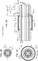
Figs. 1A to 1D are views explaining a fluid heating device of an engine according to a first embodiment of the present invention, whereinFig. 1A is a side view of the fluid heating device,Fig. 1B is a sectional view taken along line B-B inFig. 1A, Fig. 1C is a sectional view taken along line C-C inFig. 1A, and Fig. 1D is a sectional view taken along line D-D inFig. 1B ; -
Fig. 2 is a schematic view of an engine incorporating the fluid heating device of the engine according to the first embodiment of the present invention; -
Figs. 3A to 3C are views explaining a fluid heating device of an engine according to a second embodiment of the present invention, whereinFig. 3A is a longitudinal side view,Fig. 3B is an arrow view of a heat radiation pipe as viewed from direction B inFig. 3A, and Fig. 3C is a sectional view taken along line C-C inFig. 3A ; -
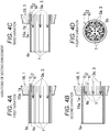
Figs. 4A to 4D are views explaining variations of the second embodiment of the present invention, whereinFig. 4A is a longitudinal side view of an end part of a first variation,Fig. 4B is a longitudinal side view of an end part of a second variation,Fig. 4C is a longitudinal side view of an end part of a third variation, andFig. 4D is a view corresponding toFig. 1B of a heat radiation pipe in a fourth variation; -
Figs. 5A to 5E are views explaining a basic example and variations of a third embodiment of the present invention, whereinFig. 5A is a view corresponding toFig. 1B of a heat radiation pipe in the basic example,Fig. 5B is a longitudinal side view of an end part in a first variation,Fig. 5C is a longitudinal side view of an end part in a second variation,Fig. 5D is a longitudinal side view of an end part in a third variation, andFig. 5E is a view corresponding toFig. 3B of a heat radiation pipe in a fourth variation; and -
Figs. 6A to 6D are views explaining a fluid heating device of an engine according to a fourth embodiment of the present invention, whereinFig. 6A is a longitudinal side view,Fig. 6B is an arrow view of a heat radiation pipe as viewed from direction B inFig. 6A, Fig. 6C is a sectional view taken along line C-C inFig. 6A, and Fig. 6D is a developed view of a coil housing body. -
Figs. 1A to 6D are views explaining a fluid heating device of an engine according to first to fourth embodiments of the present invention. In the respective embodiments, a fluid heating device for a vertical diesel engine is described. The fluid heating device may be used in respect of alternate engine types, however. - The first embodiment shown in
Figs. 1A to 1D is described. - This fluid heating device includes a heat radiation pipe (2), and is configured so that heat of the heat radiation pipe (2) is radiated to a fluid (3) passing through an inside of the heat radiation pipe (2).
- The fluid (3) is, for example, a blowby gas (3a).
- Since this fluid heating device includes an IH coil (4) for inductively heating the heat radiation pipe (2), the heat radiation pipe (2) can serve as a heat source by the induction heating of the IH coil (4). The heat is directly conducted from the heat source to the fluid (3), and there is no room for occurrence of thermal conducting loss from the heat source to the fluid. Heat transfer efficiency is high, and heat efficiency of the heat source for heating the fluid (3) is high. Power consumption of the heat source required for heating the fluid (3) can be reduced.
- The heat radiation pipe (2) is a heat radiation conveyance pipe for conveying the fluid (3), such as the blowby gas (3a), a drain oil (3b), and a liquid fuel.
- The heat radiation pipe (2) is a steel pipe.
- The heat radiation pipe (2) may be a pipe made of the other metal, such as copper or aluminum.
- The IH is an abbreviation for induction heating, and the induction heating refers to heating by causing a current to flow using a principle of electromagnetic induction.
- This fluid heating device includes a power supply (9), and an energization circuit (10) for electrically connecting the power supply (9) and the IH coil (4). The energization circuit (10) includes a key switch (11), a timer (12), and an IH control circuit (13). During engine operation in which the key switch (11) is turned into an engine operation position (11a), the heat radiation pipe (2) is inductively heated by energization from the power supply (9) to the IH coil (4) until a set time of the timer (12) elapses.
- The IH control circuit (13) includes an inverter circuit part for transmitting a high frequency power to the IH coil (4) and a control part for controlling the inverter circuit part.
- The power supply (9) is a battery.
- In this fluid heating device, a whole periphery of the heat radiation pipe (2) is surrounded by the IH coil (4). Accordingly, the whole periphery of the heat radiation pipe (2) is inductively heated by the IH coil (4), and heating efficiency of the fluid (3) can be enhanced.
- In this fluid heating device, the IH coil (4) is supported by the heat radiation pipe (2). Accordingly, even when the IH coil (4) receives vibrations of the engine, a relative arrangement between the IH coil (4) and the heat radiation pipe (2) is hardly changed, and fluctuations in an induction heating amount of the heat radiation pipe (2) caused by the vibrations can be suppressed.
- This fluid heating device includes a holder (1), and the IH coil (4) is supported by the heat radiation pipe (2) via the holder (1). Accordingly, in this fluid heating device, electric leakage from the IH coil (4) to the heat radiation pipe (2) can be suppressed.
- The holder (1) is an electrical insulator made of synthetic resin.
- In this fluid heating device, the holder (1), to which the IH coil (4) is attached, is detachably supported by the heat radiation pipe (2). Accordingly, the IH coil (4) can be easily supported by the heat radiation pipe (2) via the holder (1).
- In this fluid heating device, the holder (1) includes a case-shaped holder (17) and a tubular holder (16).
- The case-shaped holder (17) includes a tubular case peripheral wall (17a) and case end walls (17b) (17c) provided at both end parts in an axial length direction thereof. The heat radiation pipe (2) is penetrated through both the case end walls (17b) (17c), and the case-shaped holder (17) is supported by the heat radiation pipe (2) via both the case end walls (17b) (17c).
- The tubular holder (16) is attached to the case-shaped holder (17) inside the case-shaped holder (17).
- The IH coil (4) is attached to the tubular holder (16) inside the case-shaped holder (17).
- Inside the case-shaped holder (17), the heat radiation pipe (2) is concentrically surrounded from an outer periphery by the tubular holder (16) and the IH coil (4) on an outside thereof.
- Because of this, in this fluid heating device, the tubular holder (16) and the IH coil (4) are compactly supported inside the case-shaped holder (17).
- The case-shaped holder (17) and the tubular holder (16) are electrical insulators made of synthetic resin.
- Both of the case-shaped holder (17) and the tubular holder (16) are electrical and thermal insulators made of synthetic resin.
- As shown in
Fig. 1D , a heat insulating air layer (1b) is provided between the heat radiation pipe (2) and the tubular holder (16), and another heat insulating air layer (1c) is provided between the tubular holder (16) and a peripheral wall (17a) of the case-shaped holder (17). The IH coil (4) is housed inside the latter heat insulating air layer (1c). - In this fluid heating device, the case-shaped holder (17) includes a pair of half case portions (17d) (17e) divided along the axial length direction thereof, a hinge (17f) for openably connecting the pair of half case portions (17d) (17e), and an engagement part (17g) for holding the pair of half case portions (17d) (17e) in a closed state.
- In this fluid heating device, by closing the pair of half case portions (17d) (17e) opened on both sides of the outer periphery of the heat radiation pipe (2), the penetrated heat radiation pipe (2) is sandwiched between both the case end walls (17b) (17c) of the pair of half case portions (17d) (17e), and the case-shaped holder (17) is configured to be supported by the heat radiation pipe (2). Accordingly, supporting work of the case-shaped holder (17) is facilitated.
- In this fluid heating device, the tubular holder (16) includes a pair of semi-tubular portions (16a) (16b) divided along an axial length direction thereof.
- The pair of semi-tubular portions (16a) (16b) of the tubular holder (16) is respectively attached to the pair of half case portions (17d) (17e) of the case-shaped holder (17).
- In this fluid heating device, by closing the pair of half case portions (17d) (17e) opened on both the sides of the outer periphery of the heat radiation pipe (2), the pair of semi-tubular portions (16a) (16b) is configured to be the tubular holder (16) combined in a tubular form. Accordingly, assembling work of the tubular holder (16) is facilitated.
- As shown in
Fig. 1C , the pair of semi-tubular portions (16a) (16b) of the tubular holder (16) is individually attached to the pair of half case portions (17d) (17e) by a pair of attachment plates (16c) (16d). Both of the pair of attachment plates (16c) (16d) are electrical and thermal insulators made of synthetic resin. - In this fluid heating device, the IH coil (4) is configured with a pair of connectors (4a) (4b) respectively attached to respective end parts in a circumferential direction of the semi-tubular portions (16a) (16b) and a plurality of semi-arcuate electric wires (4c) disposed between the pair of connectors (4a) (4b).
- By closing the pair of half case portions (17d) (17e) opened on both the sides of the outer periphery of the heat radiation pipe (2), the plurality of semi-arcuate electric wires (4c) (4c) is connected by bonding the connector (4a) attached to one of the pair of semi-tubular portions (16a) (16b) of the tubular holder (16) and the connector (4b) attached to another thereof, and the spiral IH coil (4) swirling around the outer periphery of the tubular holder (16) is configured to be formed with the connected plurality of electric wires (4c) (4c).
- Because of this, in this fluid heating device, assembling work of the IH coil (4) is facilitated.
- One of the pair of connectors (4a) (4b) to be bonded is a male connector and another thereof is a female connector.
- As shown in
Figs. 1A to 1D , the one of the pair of connectors (4a) (4b) is the male connector and the other thereof is the female connector. One end part of the spiral IH coil (4) is provided with a positive side terminal (4d) electrically connecting with a positive electrode of the power supply (9), and another end part thereof is provided with a negative side terminal (4e) electrically connecting with a negative electrode of the power supply (9) through ground. - As shown in
Fig. 2 , the engine provided with the fluid heating device includes a cylinder block (23), a cylinder head (24) assembled to an upper part of the cylinder block (23), a cylinder head cover (25) assembled to an upper part of the cylinder head (24), a breather chamber (18) provided on the cylinder head cover (25), an intake passage (19) and an exhaust passage (26) connected to the cylinder head (24), an air cleaner (27) connected to the intake passage (19), and an oil pan (28) provided at a lower part of the cylinder block (23). A blowby gas passage (20) is provided between the breather chamber (18) and the intake passage (19), and an oil separator (21) is disposed in the middle of the blowby gas passage (20). - Of the blowby gas passage (20), a first metallic pipe (20a) is disposed between a blowby gas outlet (18a) of the breather chamber (18) and a blowby gas inlet (21a) of the oil separator (21), and a second metallic pipe (20b) is disposed between a blowby gas outlet (21b) of the oil separator (21) and a blowby gas inlet (19a) of the intake passage (19).
- In this fluid heating device, by closing the pair of semi-tubular portions (16a) (16b) on both sides of outer peripheries of the metallic pipes (20a) (20b) at an arbitrary position of the metallic pipes (20a) (20b), the IH coil (4) is attached to the arbitrary position of the metallic pipes (20a) (20b) via the holder (1).
- Because of this, a degree of freedom of arranging the IH coil (4) of this fluid heating device is high.
- In this case, the fluid (3) to be heated is the blowby gas (3a).
- As shown in
Fig. 2 , this fluid heating device of the first embodiment is also used for an oil drain passage (22) of the oil separator (21) disposed between the breather chamber (18) and the intake passage (19). In this case, the heat radiation pipe (2) is configured with a metallic pipe (22a) of the oil drain passage (22). As with the metallic pipes (20a) (20b) of the blowby gas passage (20), the IH coil (4) is configured to be attached to an arbitrary position of the metallic pipe (22a) of the oil drain passage (22). - Because of this, a degree of freedom of arranging the IH coil (4) is high in this fluid heating device.
- In this case, the fluid (3) to be heated is the drain oil (3b).
- The metallic pipe (22a) of the oil drain passage (22) is plumbed between an oil drain outlet (21c) of the oil separator (21) and an oil drain inlet (28a) of the oil pan (28).
- Next, a basic example of a second embodiment shown in
Figs. 3A to 3C is described. - As shown in
Figs. 3A, 3C , an IH coil (4) is disposed outside of a holder (1). Because of this, in this basic example, there is no need to take out a wiring line from inside of the holder (1) to outside of the holder (1), and wiring work is facilitated. Further, in this basic example, the IH coil (4) can be replaced outside of the holder (1) when the IH coil (4) fails, and repair is facilitated. - As shown in
Figs. 3A and 3C , the spiral IH coil (4) is externally fitted to the holder (1). Because of this, a whole periphery of a heat radiation pipe (2) is inductively heated by the IH coil (4), and heating efficiency of the heat radiation pipe (2) can be enhanced. - As shown in
Figs. 3A, 3C , the IH coil (4) is covered with a cylindrical cover (14). The holder (1) includes a tubular holder (16) and a pair of arcuate spacers (15) (15). The tubular holder (16) is externally fitted and fixed to the heat radiation pipe (2). The spacer (15) has elasticity and flexibility, and is curved into an arc shape along an outer periphery of the tubular holder (16). Both end parts (15a) (15a) in a curving direction face each other. Both the end parts (15a) (15a) are opened against elastic force, and both the end parts (15a) (15a) are brought close to each other by the elastic force. Accordingly, both the end parts (15a) (15a) are attached to the outer periphery of the tubular holder (16) or detached from the outer periphery of the tubular holder (16). - Both of the tubular holder (16) and the pair of arcuate spacers (15) (15) configuring the holder (1) are electrical and thermal insulators made of synthetic resin.
- As shown in
Figs. 3A to 3C , the heat radiation pipe (2) includes an outer pipe (5) and an inner pipe (6) housed inside this outer pipe (5), and a fluid (3) passing through an inside of the heat radiation pipe (2) is configured to be heated by radiation heat from the outer pipe (5) and the inner pipe (6). - Because of this, in this fluid heating device, a heat radiation area of the fluid (3) can be increased, and heat radiation can be performed on the fluid (3) passing through a center part of the outer pipe (5) at a short distance from the inner pipe (6). Heating efficiency of the fluid (3) can be enhanced.
- As shown in
Figs. 3A to 3C , the inner pipe (6) is configured with radial folds (7) whose peripheral wall is alternately folded back inside and outside, as viewed from a direction parallel to a center axis (5b) of the outer pipe (5). Because of this, a heat radiation area of the inner pipe (6) can be increased, and the heating efficiency of the fluid (3) can be enhanced. - As shown in
Figs. 3B, 3C , the outer pipe (5) is a round pipe. - In the basic example of the second embodiment shown in
Figs. 3A to 3C , the following configuration is employed. - The only one inner pipe (6) is used and disposed concentrically with the outer pipe (5). A direction of the folds (7) extending in an axial length direction of the outer pipe (5) is parallel to the center axis (5b) of the outer pipe (5).
- Both of an end part (5a) of the outer pipe (5) and an end part (6a) of the inner pipe (6) are not protruded outward from an end part (1a) of the holder (1), that is, an end part (16a) of the tubular holder (16).
- The outer pipe (5) and the inner pipe (6) are steel pipes.
- The outer pipe (5) and the inner pipe (6) may be pipes made of the other metal, such as copper or aluminum.
- Other structures of the basic example of the second embodiment shown in
Figs. 3A to 3C are the same as those in the first embodiment shown inFigs. 1A to 1D . InFigs. 3A to 3C , the same reference signs as those inFigs. 1A to 1D are used to designate elements identical to those in the first embodiment. - First to third variations of the second embodiment shown in
Figs. 4A to 4C are described. - In the basic example of the second embodiment shown in
Fig. 3A , both of the respective end parts (5a) (6a) of the outer pipe (5) and the inner pipe (6) do not protrude outward from the end part (1a) of the holder (1), that is, the end part (16a) of the tubular holder (16). - Contrary to this, in the first variation of the second embodiment shown in
Fig. 4A , one end part (5a) of an outer pipe (5) and one end part (6a) of an inner pipe (6), which are on the same side, are protruded outward from one end part (1a) of a holder (1). In the second variation of the second embodiment shown inFig. 4B , only one end part (5a) of an outer pipe (5) is protruded outward from one end part (1a) of a holder (1). In the third variation of the second embodiment shown inFig. 4C , only one end part (6a) of an inner pipe (6) is protruded outward from one end part (1a) of a holder (1). - In the present invention, at least one end part of the respective both end parts (5a) (6a) of the outer pipe (5) and the inner pipe (6) may be protruded outward from the end part (1a) of the holder (1).
- Other structures of the first to third variations of the second embodiment shown in
Figs. 4A to 4C are the same as those in the basic example of the second embodiment shown inFigs. 3A to 3C . - A fourth variation of the second embodiment shown in
Fig. 4D is described. - In the basic example of the second embodiment shown in
Figs. 3A to 3C and the first to third variations of the second embodiment shown inFigs. 4A to 4C , a direction of the folds (7) extending in an axial length direction of the outer pipe (5) is parallel to the center axis (5b) of the outer pipe (5). - Contrary to this, in the fourth variation of the second embodiment shown in
Fig. 4D , folds (7) extending in an axial length direction of an outer pipe (5) intersect in an inclined manner with a direction parallel to a center axis (5b) of the outer pipe (5). - This fold (7) is spirally twisted around the center axis (5b) of the outer pipe (5). The fold (7) may be formed straight and not twisted.
- Other structures of the fourth variation of the second embodiment shown in
Fig. 4D are the same as those in the basic example of the second embodiment shown inFigs. 3A to 3C . - A structure of the fourth variation of the second embodiment shown in
Fig. 4D can be used in combination with the structures of the first to third variations of the second embodiment shown inFigs. 4A to 4C . - A structure of the heat radiation pipe (2) formed of the inner and outer pipes in the basic example and the respective variations of the second embodiment shown in
Figs. 3A to 3C ,Figs. 4A to 4D can be used in the first embodiment shown inFigs 1A to 1D . - A basic example of a third embodiment shown in
Fig. 5A is described. - In the basic example of the second embodiment shown in
Fig. 3A , the only one inner pipe (6) is used and disposed concentrically with the outer pipe (5). - Contrary to this, in the basic example of the third embodiment shown in
Fig. 5A , a plurality of inner pipes (6) is bundled and disposed inside an outer pipe (5). - All of the inner pipes (6) are round pipes.
- Other structures of the basic example of the third embodiment shown in
Fig. 5A are the same as those in the basic example of the second embodiment shown inFigs. 3A to 3C . InFig. 5A , the same reference signs as those inFig. 3B are used to designate elements identical to those in the basic example of the second embodiment. - First to third variations of the third embodiment shown in
Figs. 5B to 5D are described. - In the basic example of the third embodiment shown in
Fig. 5A , as with the basic example of the second embodiment shown inFig. 3A , both of respective end parts (5a) (6a) of the outer pipe (5) and the inner pipe (6) are not protruded outward from an end part (1a) of a holder (1), that is, an end part (16a) of a tubular holder (16). - Contrary to this, in the first variation of the third embodiment shown in
Fig. 5B , one end part (5a) of an outer pipe (5) and one end part (6a) of an inner pipe (6), which are on the same side, are protruded outward from an end part (1a) of a holder (1). In the second variation of the third embodiment shown inFig. 5C , only one end part (5a) of an outer pipe (5) is protruded outward from an end part (1a) of a holder (1). In the third variation of the third embodiment shown inFig. 5D , only one end part (6a) of an inner pipe (6) is protruded outward from an end part (1a) of a holder (1). - In the present invention, at least one end part of the respective both end parts (5a) (6a) of the outer pipe (5) and the inner pipe (6) may be protruded outward from the end part (1a) of the holder (1).
- Other structures of the first to third variations of the third embodiment shown in
Figs. 5B to 5D are the same as those in the basic example of the second embodiment shown inFig. 3A . -
Fig. 5E shows a fourth variation of the third embodiment. - In the basic example of the third embodiment shown in
Fig. 5A and the first to third variations of the third embodiment shown inFigs. 5B to 5D , a direction of the inner pipe (6) is parallel to a center axis (5b) of the outer pipe (5). - Contrary to this, in the fourth variation of the third embodiment shown in
Fig. 5E , an inner pipe (6) intersects in an inclined manner with a direction parallel to a center axis (5b) of an outer pipe (5). - This inner pipe (6) is spirally twisted around the center axis (5b) of the outer pipe (5). The inner pipe (6) may be formed straight and not twisted.
- Other structures of the fourth variation of the third embodiment shown in
Fig. 5E are the same as those in the basic example of the third embodiment shown inFigs. 5A . - A structure of the fourth variation of the third embodiment shown in
Fig. 5E can be used in combination with the structures of the first to third variations of the third embodiment shown inFigs. 5B to 5D . - A fourth embodiment shown in
Figs. 6A to 6D is described. - As shown in
Figs. 6A, 6C, 6D , an IH coil (4) is housed in a coil housing body (8). As shown inFig. 6C , in a state in which the coil housing body (8) is curved along an outer periphery of a holder (1), curving direction both end edge parts (8a) (8a) face each other. The coil housing body (8) has flexibility and is detachably attached to the outer periphery of the holder (1). Because of this, the coil housing body (8) can be attached to the outer periphery of the holder (1) or the coil housing body (8) can be detached from the outer periphery of the holder (1) by opening the curving direction both end edge parts (8a) (8a). The IH coil (4) is easily attached to or detached from the holder (1). - The coil housing body (8) is made of synthetic resin having elasticity, and is a rectangle when it is developed as shown in
Fig. 6D . As shown inFig. 6C , the coil housing body (8) is curved into an arc shape along the outer periphery of the holder (1), and the curving direction both end edge parts (8a) (8a) face each other. Both the end edge parts (8a) (8a) are opened against elastic force. By bringing both the end edge parts (8a) (8a) close to each other by the elastic force, the coil housing body (8) is attached to the outer periphery of the holder (1). Alternatively, both the end edge parts (8a) (8a) are opened against the elasticity, and the coil housing body (8) is detached from the outer periphery of the holder (1). - The IH coil (4) is embedded in the coil housing body (8). The holder (1) is configured with a tubular holder (16), and the tubular holder (16) is externally fitted and fixed to a heat radiation pipe (2).
- Other structures of the fourth embodiment shown in
Figs. 6A to 6D are the same as those in the basic example of the second embodiment shown inFigs. 3A to 3C . InFigs. 6A to 6D , the same reference signs as those inFigs. 3A to 3C are used to designate elements identical to those in the basic example of the second embodiment. - In the fluid heating device of an engine in the respective basic examples and the respective variations of the second to fourth embodiments shown in
Figs. 3A to 6D , the one end part (1a) of the holder (1) is inserted into the blowby gas inlet (21a) of the oil separator (21) shown inFig. 2 , and a blowby gas introduction pipe (not shown) led out from a breather device (not shown) of the engine is connected to the other end part (1a) thereof. The blowby gas (3a) introduced from the breather chamber (18) into the oil separator (21) is heated. The fluid heating device can be used to prevent freezing of moisture contained in the blowby gas (3a) and to prevent closing of the blowby gas passage (20) at cold start or subsequent warm-up operation of the engine. Further, the one end part (1a) of the holder (1) is inserted into the blowby gas outlet (21b) of the oil separator (21), and a blowby gas leading-out pipe (not shown) communicated with the intake passage (19) is connected to the other end part (1a) thereof. The blowby gas (3a) led out from the oil separator (21) into the intake passage (19) is heated. The fluid heating device can be used to prevent freezing of moisture contained in the blowby gas (3a) and to prevent closing of the blowby gas passage (20) at cold start or subsequent warm-up operation of the engine. Further, this fluid heating device of the engine can be disposed at an arbitrary position in the middle of the blowby gas passage (20). - Further, the fluid heating device of the engine in the respective basic examples and the respective variations of the second to fourth embodiments shown in
Figs. 3A to 6D , the one end part (1a) of the holder (1) is inserted into a fuel inlet of a fuel supply pump (not shown), and a fuel introduction pipe (not shown) led out from a fuel tank (not shown) of the engine is connected to the other end part (1a) thereof. Fuel introduced from the fuel tank to the fuel supply pump is heated. The fluid heating device can be used to prevent freezing of the fuel in the fuel supply pump and to prevent closing of a fuel passage at cold start or subsequent warm-up operation of the engine. Further, the one end part (1a) of the holder (1) is inserted into a fuel outlet of the fuel supply pump (not shown), and a fuel leading-out pipe (not shown) communicated with a fuel injection pump (not shown) of a diesel engine is connected to the other end part (1a) thereof. Fuel led out from the fuel supply pump to the fuel injection pump is heated. The fluid heating device can be used to prevent freezing of moisture contained in the fuel and to prevent closing of the fuel passage at cold start or subsequent warm-up operation of the engine. Further, this fluid heating device of the engine can be disposed at an arbitrary position of the fuel passage, such as in the middle of the fuel supply pipe. The first embodiment shown inFigs. 1A to 1D can be also used as a fuel heating device.
Claims (20)
- A fluid heating device of an engine which includes a heat radiation pipe (2) and is configured so that heat of the heat radiation pipe (2) is radiated to a fluid (3) passing through an inside of the heat radiation pipe (2), the device comprising:an IH coil (4) for inductively heating the heat radiation pipe (2).
- The fluid heating device of the engine according to claim 1, wherein
a whole periphery of the heat radiation pipe (2) is surrounded by the IH coil (4). - The fluid heating device of the engine according to claim 1 or 2, wherein
the IH coil (4) is supported by the heat radiation pipe (2). - The fluid heating device of the engine according to claim 3, wherein
a holder (1) is included, and the IH coil (4) is supported by the heat radiation pipe (2) via the holder (1). - The fluid heating device of the engine according to claim 4, wherein
the holder (1), to which the IH coil (4) is attached, is detachably supported by the heat radiation pipe (2). - The fluid heating device of the engine according to claim 4 or 5, wherein
the holder (1) includes a case-shaped holder (17) and a tubular holder (16),
the case-shaped holder (17) includes a tubular case peripheral wall (17a) and case end walls (17b, 17c) provided at both end parts in an axial length direction of the case-shaped holder (17), the heat radiation pipe (2) is penetrated through both the case end walls (17b, 17c), and the case-shaped holder (17) is supported by the heat radiation pipe (2) via both the case end walls (17b, 17c),
the tubular holder 16 is attached to the case-shaped holder (17) inside the case-shaped holder (17),
the IH coil (4) is attached to the tubular holder (16) inside the case-shaped holder (17), and
inside the case-shaped holder (17), the heat radiation pipe (2) is concentrically surrounded from an outer periphery by the tubular holder (16) and the IH coil (4) on outside of the tubular holder (16). - The fluid heating device of the engine according to claim 6, wherein
the case-shaped holder (17) includes a pair of half case portions (17d, 17e) divided along the axial length direction of the case-shaped holder (17), a hinge (17f) for openably connecting the pair of half case portions (17d, 17e), and an engagement part (17g) for holding the pair of half case portions (17d, 17e) in a closed state, and
by closing the pair of half case portions (17d, 17e) opened on both sides of the outer periphery of the heat radiation pipe (2), the penetrated heat radiation pipe (2) is sandwiched between both the case end walls (17b, 17c) of the pair of half case portions (17d, 17e), and the case-shaped holder (17) is configured to be supported by the heat radiation pipe (2). - The fluid heating device of the engine according to claim 7, wherein
the tubular holder (16) includes a pair of semi-tubular portions (16a, 16b) divided along an axial length direction of the tubular holder (16),
the pair of semi-tubular portions (16a, 16b) of the tubular holder (16) is respectively attached to the pair of half case portions (17d, 17e) of the case-shaped holder (17), and
by closing the pair of half case portions (17d, 17e) opened on both the sides of the outer periphery of the heat radiation pipe (2), the pair of semi-tubular portions (16a, 16b) is configured to be the tubular holder (16) combined in a tubular form. - The fluid heating device of the engine according to claim 8, wherein
the IH coil (4) is configured with a pair of connectors (4a, 4b) respectively attached to respective end parts in a circumferential direction of the semi-tubular portions (16a, 16b) and a plurality of semi-arcuate electric wires (4c) disposed between the pair of connectors (4a, 4b),
by closing the pair of half case portions (17d, 17e) opened on both the sides of the outer periphery of the heat radiation pipe (2), the plurality of semi-arcuate electric wires (4c, 4c) is connected by bonding the connector (4a) attached to one of the pair of semi-tubular portions (16a, 16b) of the tubular holder (16) and the connector (4b) attached to another of the pair of semi-tubular portions (16a, 16b), and the spiral IH coil 4 swirling around an outer periphery of the tubular holder (16) is configured to be formed with the connected plurality of electric wires (4c, 4c). - The fluid heating device of the engine according to any of claims 1 to 9, wherein
the heat radiation pipe (2) is configured with metallic pipes (20a, 20b) of a blowby gas passage (20) disposed between a breather chamber (18) and an intake passage (19), and the IH coil (4) is configured to be attached to an arbitrary position of these metallic pipes (20a, 20b). - The fluid heating device of the engine according to any of claims 1 to 9, wherein
the heat radiation pipe (2) is configured with a metallic pipe (22a) of an oil drain passage (22) of an oil separator (21) disposed between the breather chamber (18) and the intake passage (19), and the IH coil (4) is configured to be attached to an arbitrary position of this metallic pipe (22a). - The fluid heating device of the engine according to claim 4, wherein
the IH coil (4) is disposed outside of the holder (1). - The fluid heating device of the engine according to claim 12, wherein
the spiral IH coil (4) is externally fitted to the holder (1). - The fluid heating device of the engine according to claim 13, wherein
the IH coil (4) is supported by a coil housing body (8), curving direction both end edge parts (8a, 8a) face each other in a state in which the coil housing body (8) is curved along an outer periphery of the holder (1), and the coil housing body (8) has flexibility and is detachably attached to the outer periphery of the holder (1). - The fluid heating device of the engine according to any of claims 1 to 4, wherein
the heat radiation pipe (2) includes an outer pipe (5) and an inner pipe (6) housed inside this outer pipe (5), and the fluid (3) passing through the inside of the heat radiation pipe (2) is configured to be heated by radiation heat from the outer pipe (5) and the inner pipe (6). - The fluid heating device of the engine according to claim 15, wherein
at least one end part of respective end parts (5a, 6a) of the outer pipe (5) and the inner pipe (6) is protruded outward from the end part (1a) of the holder (1). - The fluid heating device of the engine according to claim 15 or 16, wherein
the inner pipe (6) is configured with radial folds (7) whose peripheral wall is alternately folded back inside and outside, as viewed from a direction parallel to a center axis (5b) of the outer pipe (5). - The fluid heating device of the engine according to claim 17, wherein
the folds (7) of the inner pipe (6) extend in an axial length direction of the outer pipe (5) and intersect in an inclined manner with the direction parallel to the center axis (5b) of the outer pipe (5). - The fluid heating device of the engine according to claim 15 or 16, wherein
a plurality of the inner pipes (6) are bundled and disposed inside the outer pipe (5). - The fluid heating device of the engine according to claim 19, wherein
the inner pipes (6) intersect in an inclined manner with the direction parallel to the center axis (5b) of the outer pipe (5).
Applications Claiming Priority (2)
| Application Number | Priority Date | Filing Date | Title |
|---|---|---|---|
| JP2016007918 | 2016-01-19 | ||
| JP2016110093A JP6543218B2 (en) | 2016-01-19 | 2016-06-01 | Engine fluid heating device |
Publications (2)
| Publication Number | Publication Date |
|---|---|
| EP3196067A1 true EP3196067A1 (en) | 2017-07-26 |
| EP3196067B1 EP3196067B1 (en) | 2019-04-24 |
Family
ID=57394353
Family Applications (1)
| Application Number | Title | Priority Date | Filing Date |
|---|---|---|---|
| EP16199038.7A Active EP3196067B1 (en) | 2016-01-19 | 2016-11-16 | Fluid heating device of engine |
Country Status (3)
| Country | Link |
|---|---|
| US (1) | US10524314B2 (en) |
| EP (1) | EP3196067B1 (en) |
| CN (1) | CN106979050B (en) |
Cited By (1)
| Publication number | Priority date | Publication date | Assignee | Title |
|---|---|---|---|---|
| JP2017129113A (en) * | 2016-01-19 | 2017-07-27 | 株式会社クボタ | Engine fluid heating device |
Families Citing this family (4)
| Publication number | Priority date | Publication date | Assignee | Title |
|---|---|---|---|---|
| CN109812358A (en) * | 2017-11-21 | 2019-05-28 | 上海汽车集团股份有限公司 | a heating system |
| CN108386292B (en) * | 2018-03-09 | 2019-11-08 | 南京隆尼精密机械有限公司 | Engine cylinder block |
| CN110541742B (en) * | 2018-05-29 | 2021-12-21 | 长城汽车股份有限公司 | Oil-gas dehumidifier for vehicle and vehicle with same |
| CN110671168A (en) * | 2019-10-25 | 2020-01-10 | 一汽解放汽车有限公司 | A crankcase ventilation heating device for preventing oil emulsification |
Citations (7)
| Publication number | Priority date | Publication date | Assignee | Title |
|---|---|---|---|---|
| WO2007109715A1 (en) * | 2006-03-21 | 2007-09-27 | Continental Automotive Systems Us, Inc. | Fuel injector with inductive heater |
| DE102006058881A1 (en) * | 2006-12-13 | 2008-06-19 | Siemens Ag | Nozzle assembly for an injection valve and injection valve |
| US20100133363A1 (en) * | 2008-12-03 | 2010-06-03 | Continental Automotive Systems Us, Inc. | Multi-point low pressure inductively heated fuel injector with heat exchanger |
| JP2011027007A (en) * | 2009-07-23 | 2011-02-10 | Nippon Soken Inc | Fuel heating device for internal combustion engine |
| KR101059744B1 (en) * | 2011-01-13 | 2011-08-26 | 한국기계연구원 | Automobile smoke reduction device using high frequency induction heating |
| JP2013124566A (en) | 2011-12-13 | 2013-06-24 | Akio Matsumoto | Blow-by gas heater |
| JP2015151063A (en) * | 2014-02-18 | 2015-08-24 | 株式会社デンソー | heat exchange system |
Family Cites Families (10)
| Publication number | Priority date | Publication date | Assignee | Title |
|---|---|---|---|---|
| JPS51138246A (en) | 1975-05-26 | 1976-11-29 | Fumihiro Horie | Engine combustion mode |
| US5329913A (en) * | 1991-03-26 | 1994-07-19 | Yamaha Hatsudoki Kabushiki Kaisha | Oil vapor separator system for the engine of a gas heat pump air conditioner |
| JP4683483B2 (en) * | 2006-02-14 | 2011-05-18 | 本田技研工業株式会社 | Engine with breather device |
| WO2008048486A1 (en) * | 2006-10-13 | 2008-04-24 | Black & Decker Inc. | Anchoring system for a stator housing assembly having an overmolding; power tool with same |
| JP2009277547A (en) * | 2008-05-15 | 2009-11-26 | Omron Corp | Electromagnetic induction heating type fluid heating device |
| CN201359330Y (en) * | 2008-12-31 | 2009-12-09 | 珠海慧生能源技术发展有限公司 | Superconducting superaudio electric room heater |
| JP5537279B2 (en) | 2010-06-18 | 2014-07-02 | 日本パイオニクス株式会社 | Piping heating equipment |
| CN103016099B (en) * | 2012-12-25 | 2015-04-15 | 中国第一汽车股份有限公司 | Ventilating and heating system of crankcase |
| CN204061021U (en) * | 2014-03-31 | 2014-12-31 | 石河子开发区建通公路工程有限责任公司 | With the motor of multipurpose mechanically activated heater in winter |
| CN104500173A (en) * | 2014-12-25 | 2015-04-08 | 绵阳新晨动力机械有限公司 | Blow-by gas heating pipeline of supercharged gasoline engine crankcase |
-
2016
- 2016-11-16 EP EP16199038.7A patent/EP3196067B1/en active Active
- 2016-12-01 CN CN201611093218.1A patent/CN106979050B/en active Active
- 2016-12-01 US US15/366,723 patent/US10524314B2/en active Active
Patent Citations (7)
| Publication number | Priority date | Publication date | Assignee | Title |
|---|---|---|---|---|
| WO2007109715A1 (en) * | 2006-03-21 | 2007-09-27 | Continental Automotive Systems Us, Inc. | Fuel injector with inductive heater |
| DE102006058881A1 (en) * | 2006-12-13 | 2008-06-19 | Siemens Ag | Nozzle assembly for an injection valve and injection valve |
| US20100133363A1 (en) * | 2008-12-03 | 2010-06-03 | Continental Automotive Systems Us, Inc. | Multi-point low pressure inductively heated fuel injector with heat exchanger |
| JP2011027007A (en) * | 2009-07-23 | 2011-02-10 | Nippon Soken Inc | Fuel heating device for internal combustion engine |
| KR101059744B1 (en) * | 2011-01-13 | 2011-08-26 | 한국기계연구원 | Automobile smoke reduction device using high frequency induction heating |
| JP2013124566A (en) | 2011-12-13 | 2013-06-24 | Akio Matsumoto | Blow-by gas heater |
| JP2015151063A (en) * | 2014-02-18 | 2015-08-24 | 株式会社デンソー | heat exchange system |
Cited By (1)
| Publication number | Priority date | Publication date | Assignee | Title |
|---|---|---|---|---|
| JP2017129113A (en) * | 2016-01-19 | 2017-07-27 | 株式会社クボタ | Engine fluid heating device |
Also Published As
| Publication number | Publication date |
|---|---|
| EP3196067B1 (en) | 2019-04-24 |
| CN106979050B (en) | 2020-10-27 |
| CN106979050A (en) | 2017-07-25 |
| US20170208651A1 (en) | 2017-07-20 |
| US10524314B2 (en) | 2019-12-31 |
Similar Documents
| Publication | Publication Date | Title |
|---|---|---|
| EP3196067B1 (en) | Fluid heating device of engine | |
| CN111819106B (en) | Inductive charging device | |
| CN104755743B (en) | preheating device for fuel injection system | |
| US9848464B2 (en) | Heating device | |
| EP3518413A1 (en) | Power conversion device | |
| KR20180091584A (en) | Coolant heater | |
| JP5841960B2 (en) | Blow-by gas heater | |
| EP2982837B1 (en) | Fluid heating device for engine | |
| RU2010130545A (en) | HIGH VOLTAGE INPUT, INPUT COOLING METHOD AND ELECTRIC POWER DISTRIBUTION SYSTEM CONTAINING SUCH INPUT | |
| CN109383220B (en) | Coolant heating device for electric vehicle | |
| US20160201901A1 (en) | Heater device for heating liquefied gas | |
| CN104471320B (en) | devices for electric heating | |
| US11566549B2 (en) | Exhaust gas heating assembly | |
| CN101021174B (en) | engine with breather | |
| JP6543218B2 (en) | Engine fluid heating device | |
| US11946407B2 (en) | Catalyst device | |
| KR20190092052A (en) | Heater assembly for heating fluid | |
| CN114747305B (en) | Converter | |
| KR200404664Y1 (en) | A induction heating appartus | |
| KR20180090573A (en) | Cooling-water heater | |
| CN108350786A (en) | For by the injector assembly in fluid metering to gas exhaust piping | |
| US20160157303A1 (en) | Heating device | |
| CN106285860A (en) | Reductant Tank with Integrated Fluid Channels for Conducting Heating Fluid | |
| RU2816941C1 (en) | Heating spraying core | |
| CN110662664A (en) | Induction heaters for vehicles |
Legal Events
| Date | Code | Title | Description |
|---|---|---|---|
| PUAI | Public reference made under article 153(3) epc to a published international application that has entered the european phase |
Free format text: ORIGINAL CODE: 0009012 |
|
| STAA | Information on the status of an ep patent application or granted ep patent |
Free format text: STATUS: THE APPLICATION HAS BEEN PUBLISHED |
|
| AK | Designated contracting states |
Kind code of ref document: A1 Designated state(s): AL AT BE BG CH CY CZ DE DK EE ES FI FR GB GR HR HU IE IS IT LI LT LU LV MC MK MT NL NO PL PT RO RS SE SI SK SM TR |
|
| AX | Request for extension of the european patent |
Extension state: BA ME |
|
| STAA | Information on the status of an ep patent application or granted ep patent |
Free format text: STATUS: REQUEST FOR EXAMINATION WAS MADE |
|
| 17P | Request for examination filed |
Effective date: 20180119 |
|
| RBV | Designated contracting states (corrected) |
Designated state(s): AL AT BE BG CH CY CZ DE DK EE ES FI FR GB GR HR HU IE IS IT LI LT LU LV MC MK MT NL NO PL PT RO RS SE SI SK SM TR |
|
| STAA | Information on the status of an ep patent application or granted ep patent |
Free format text: STATUS: EXAMINATION IS IN PROGRESS |
|
| 17Q | First examination report despatched |
Effective date: 20180612 |
|
| GRAP | Despatch of communication of intention to grant a patent |
Free format text: ORIGINAL CODE: EPIDOSNIGR1 |
|
| STAA | Information on the status of an ep patent application or granted ep patent |
Free format text: STATUS: GRANT OF PATENT IS INTENDED |
|
| INTG | Intention to grant announced |
Effective date: 20181127 |
|
| GRAS | Grant fee paid |
Free format text: ORIGINAL CODE: EPIDOSNIGR3 |
|
| GRAA | (expected) grant |
Free format text: ORIGINAL CODE: 0009210 |
|
| STAA | Information on the status of an ep patent application or granted ep patent |
Free format text: STATUS: THE PATENT HAS BEEN GRANTED |
|
| AK | Designated contracting states |
Kind code of ref document: B1 Designated state(s): AL AT BE BG CH CY CZ DE DK EE ES FI FR GB GR HR HU IE IS IT LI LT LU LV MC MK MT NL NO PL PT RO RS SE SI SK SM TR |
|
| REG | Reference to a national code |
Ref country code: GB Ref legal event code: FG4D |
|
| REG | Reference to a national code |
Ref country code: CH Ref legal event code: EP |
|
| REG | Reference to a national code |
Ref country code: AT Ref legal event code: REF Ref document number: 1123725 Country of ref document: AT Kind code of ref document: T Effective date: 20190515 Ref country code: IE Ref legal event code: FG4D |
|
| REG | Reference to a national code |
Ref country code: DE Ref legal event code: R096 Ref document number: 602016012793 Country of ref document: DE |
|
| REG | Reference to a national code |
Ref country code: NL Ref legal event code: MP Effective date: 20190424 |
|
| REG | Reference to a national code |
Ref country code: LT Ref legal event code: MG4D |
|
| PG25 | Lapsed in a contracting state [announced via postgrant information from national office to epo] |
Ref country code: NL Free format text: LAPSE BECAUSE OF FAILURE TO SUBMIT A TRANSLATION OF THE DESCRIPTION OR TO PAY THE FEE WITHIN THE PRESCRIBED TIME-LIMIT Effective date: 20190424 |
|
| PG25 | Lapsed in a contracting state [announced via postgrant information from national office to epo] |
Ref country code: AL Free format text: LAPSE BECAUSE OF FAILURE TO SUBMIT A TRANSLATION OF THE DESCRIPTION OR TO PAY THE FEE WITHIN THE PRESCRIBED TIME-LIMIT Effective date: 20190424 Ref country code: PT Free format text: LAPSE BECAUSE OF FAILURE TO SUBMIT A TRANSLATION OF THE DESCRIPTION OR TO PAY THE FEE WITHIN THE PRESCRIBED TIME-LIMIT Effective date: 20190824 Ref country code: ES Free format text: LAPSE BECAUSE OF FAILURE TO SUBMIT A TRANSLATION OF THE DESCRIPTION OR TO PAY THE FEE WITHIN THE PRESCRIBED TIME-LIMIT Effective date: 20190424 Ref country code: LT Free format text: LAPSE BECAUSE OF FAILURE TO SUBMIT A TRANSLATION OF THE DESCRIPTION OR TO PAY THE FEE WITHIN THE PRESCRIBED TIME-LIMIT Effective date: 20190424 Ref country code: HR Free format text: LAPSE BECAUSE OF FAILURE TO SUBMIT A TRANSLATION OF THE DESCRIPTION OR TO PAY THE FEE WITHIN THE PRESCRIBED TIME-LIMIT Effective date: 20190424 Ref country code: SE Free format text: LAPSE BECAUSE OF FAILURE TO SUBMIT A TRANSLATION OF THE DESCRIPTION OR TO PAY THE FEE WITHIN THE PRESCRIBED TIME-LIMIT Effective date: 20190424 Ref country code: NO Free format text: LAPSE BECAUSE OF FAILURE TO SUBMIT A TRANSLATION OF THE DESCRIPTION OR TO PAY THE FEE WITHIN THE PRESCRIBED TIME-LIMIT Effective date: 20190724 Ref country code: FI Free format text: LAPSE BECAUSE OF FAILURE TO SUBMIT A TRANSLATION OF THE DESCRIPTION OR TO PAY THE FEE WITHIN THE PRESCRIBED TIME-LIMIT Effective date: 20190424 |
|
| PG25 | Lapsed in a contracting state [announced via postgrant information from national office to epo] |
Ref country code: RS Free format text: LAPSE BECAUSE OF FAILURE TO SUBMIT A TRANSLATION OF THE DESCRIPTION OR TO PAY THE FEE WITHIN THE PRESCRIBED TIME-LIMIT Effective date: 20190424 Ref country code: PL Free format text: LAPSE BECAUSE OF FAILURE TO SUBMIT A TRANSLATION OF THE DESCRIPTION OR TO PAY THE FEE WITHIN THE PRESCRIBED TIME-LIMIT Effective date: 20190424 Ref country code: GR Free format text: LAPSE BECAUSE OF FAILURE TO SUBMIT A TRANSLATION OF THE DESCRIPTION OR TO PAY THE FEE WITHIN THE PRESCRIBED TIME-LIMIT Effective date: 20190725 Ref country code: LV Free format text: LAPSE BECAUSE OF FAILURE TO SUBMIT A TRANSLATION OF THE DESCRIPTION OR TO PAY THE FEE WITHIN THE PRESCRIBED TIME-LIMIT Effective date: 20190424 Ref country code: BG Free format text: LAPSE BECAUSE OF FAILURE TO SUBMIT A TRANSLATION OF THE DESCRIPTION OR TO PAY THE FEE WITHIN THE PRESCRIBED TIME-LIMIT Effective date: 20190724 |
|
| REG | Reference to a national code |
Ref country code: AT Ref legal event code: MK05 Ref document number: 1123725 Country of ref document: AT Kind code of ref document: T Effective date: 20190424 |
|
| PG25 | Lapsed in a contracting state [announced via postgrant information from national office to epo] |
Ref country code: IS Free format text: LAPSE BECAUSE OF FAILURE TO SUBMIT A TRANSLATION OF THE DESCRIPTION OR TO PAY THE FEE WITHIN THE PRESCRIBED TIME-LIMIT Effective date: 20190824 |
|
| REG | Reference to a national code |
Ref country code: DE Ref legal event code: R097 Ref document number: 602016012793 Country of ref document: DE |
|
| PG25 | Lapsed in a contracting state [announced via postgrant information from national office to epo] |
Ref country code: CZ Free format text: LAPSE BECAUSE OF FAILURE TO SUBMIT A TRANSLATION OF THE DESCRIPTION OR TO PAY THE FEE WITHIN THE PRESCRIBED TIME-LIMIT Effective date: 20190424 Ref country code: SK Free format text: LAPSE BECAUSE OF FAILURE TO SUBMIT A TRANSLATION OF THE DESCRIPTION OR TO PAY THE FEE WITHIN THE PRESCRIBED TIME-LIMIT Effective date: 20190424 Ref country code: RO Free format text: LAPSE BECAUSE OF FAILURE TO SUBMIT A TRANSLATION OF THE DESCRIPTION OR TO PAY THE FEE WITHIN THE PRESCRIBED TIME-LIMIT Effective date: 20190424 Ref country code: AT Free format text: LAPSE BECAUSE OF FAILURE TO SUBMIT A TRANSLATION OF THE DESCRIPTION OR TO PAY THE FEE WITHIN THE PRESCRIBED TIME-LIMIT Effective date: 20190424 Ref country code: DK Free format text: LAPSE BECAUSE OF FAILURE TO SUBMIT A TRANSLATION OF THE DESCRIPTION OR TO PAY THE FEE WITHIN THE PRESCRIBED TIME-LIMIT Effective date: 20190424 Ref country code: EE Free format text: LAPSE BECAUSE OF FAILURE TO SUBMIT A TRANSLATION OF THE DESCRIPTION OR TO PAY THE FEE WITHIN THE PRESCRIBED TIME-LIMIT Effective date: 20190424 |
|
| PG25 | Lapsed in a contracting state [announced via postgrant information from national office to epo] |
Ref country code: SM Free format text: LAPSE BECAUSE OF FAILURE TO SUBMIT A TRANSLATION OF THE DESCRIPTION OR TO PAY THE FEE WITHIN THE PRESCRIBED TIME-LIMIT Effective date: 20190424 Ref country code: IT Free format text: LAPSE BECAUSE OF FAILURE TO SUBMIT A TRANSLATION OF THE DESCRIPTION OR TO PAY THE FEE WITHIN THE PRESCRIBED TIME-LIMIT Effective date: 20190424 |
|
| PLBE | No opposition filed within time limit |
Free format text: ORIGINAL CODE: 0009261 |
|
| STAA | Information on the status of an ep patent application or granted ep patent |
Free format text: STATUS: NO OPPOSITION FILED WITHIN TIME LIMIT |
|
| PG25 | Lapsed in a contracting state [announced via postgrant information from national office to epo] |
Ref country code: TR Free format text: LAPSE BECAUSE OF FAILURE TO SUBMIT A TRANSLATION OF THE DESCRIPTION OR TO PAY THE FEE WITHIN THE PRESCRIBED TIME-LIMIT Effective date: 20190424 |
|
| 26N | No opposition filed |
Effective date: 20200127 |
|
| PG25 | Lapsed in a contracting state [announced via postgrant information from national office to epo] |
Ref country code: SI Free format text: LAPSE BECAUSE OF FAILURE TO SUBMIT A TRANSLATION OF THE DESCRIPTION OR TO PAY THE FEE WITHIN THE PRESCRIBED TIME-LIMIT Effective date: 20190424 |
|
| REG | Reference to a national code |
Ref country code: CH Ref legal event code: PL |
|
| PG25 | Lapsed in a contracting state [announced via postgrant information from national office to epo] |
Ref country code: LI Free format text: LAPSE BECAUSE OF NON-PAYMENT OF DUE FEES Effective date: 20191130 Ref country code: LU Free format text: LAPSE BECAUSE OF NON-PAYMENT OF DUE FEES Effective date: 20191116 Ref country code: CH Free format text: LAPSE BECAUSE OF NON-PAYMENT OF DUE FEES Effective date: 20191130 Ref country code: MC Free format text: LAPSE BECAUSE OF FAILURE TO SUBMIT A TRANSLATION OF THE DESCRIPTION OR TO PAY THE FEE WITHIN THE PRESCRIBED TIME-LIMIT Effective date: 20190424 |
|
| REG | Reference to a national code |
Ref country code: BE Ref legal event code: MM Effective date: 20191130 |
|
| PG25 | Lapsed in a contracting state [announced via postgrant information from national office to epo] |
Ref country code: IE Free format text: LAPSE BECAUSE OF NON-PAYMENT OF DUE FEES Effective date: 20191116 |
|
| PG25 | Lapsed in a contracting state [announced via postgrant information from national office to epo] |
Ref country code: BE Free format text: LAPSE BECAUSE OF NON-PAYMENT OF DUE FEES Effective date: 20191130 |
|
| PG25 | Lapsed in a contracting state [announced via postgrant information from national office to epo] |
Ref country code: CY Free format text: LAPSE BECAUSE OF FAILURE TO SUBMIT A TRANSLATION OF THE DESCRIPTION OR TO PAY THE FEE WITHIN THE PRESCRIBED TIME-LIMIT Effective date: 20190424 |
|
| PG25 | Lapsed in a contracting state [announced via postgrant information from national office to epo] |
Ref country code: HU Free format text: LAPSE BECAUSE OF FAILURE TO SUBMIT A TRANSLATION OF THE DESCRIPTION OR TO PAY THE FEE WITHIN THE PRESCRIBED TIME-LIMIT; INVALID AB INITIO Effective date: 20161116 Ref country code: MT Free format text: LAPSE BECAUSE OF FAILURE TO SUBMIT A TRANSLATION OF THE DESCRIPTION OR TO PAY THE FEE WITHIN THE PRESCRIBED TIME-LIMIT Effective date: 20190424 |
|
| PG25 | Lapsed in a contracting state [announced via postgrant information from national office to epo] |
Ref country code: MK Free format text: LAPSE BECAUSE OF FAILURE TO SUBMIT A TRANSLATION OF THE DESCRIPTION OR TO PAY THE FEE WITHIN THE PRESCRIBED TIME-LIMIT Effective date: 20190424 |
|
| PGFP | Annual fee paid to national office [announced via postgrant information from national office to epo] |
Ref country code: FR Payment date: 20250930 Year of fee payment: 10 |
|
| PGFP | Annual fee paid to national office [announced via postgrant information from national office to epo] |
Ref country code: DE Payment date: 20250930 Year of fee payment: 10 |
|
| PGFP | Annual fee paid to national office [announced via postgrant information from national office to epo] |
Ref country code: GB Payment date: 20251001 Year of fee payment: 10 |