EP3196043A1 - Optisch variables element mit magnetisch ausrichtbaren pigment - Google Patents
Optisch variables element mit magnetisch ausrichtbaren pigment Download PDFInfo
- Publication number
- EP3196043A1 EP3196043A1 EP17000095.4A EP17000095A EP3196043A1 EP 3196043 A1 EP3196043 A1 EP 3196043A1 EP 17000095 A EP17000095 A EP 17000095A EP 3196043 A1 EP3196043 A1 EP 3196043A1
- Authority
- EP
- European Patent Office
- Prior art keywords
- fluid
- optically variable
- emulsion
- phase
- variable element
- Prior art date
- Legal status (The legal status is an assumption and is not a legal conclusion. Google has not performed a legal analysis and makes no representation as to the accuracy of the status listed.)
- Granted
Links
Images


Classifications
-
- B—PERFORMING OPERATIONS; TRANSPORTING
- B42—BOOKBINDING; ALBUMS; FILES; SPECIAL PRINTED MATTER
- B42D—BOOKS; BOOK COVERS; LOOSE LEAVES; PRINTED MATTER CHARACTERISED BY IDENTIFICATION OR SECURITY FEATURES; PRINTED MATTER OF SPECIAL FORMAT OR STYLE NOT OTHERWISE PROVIDED FOR; DEVICES FOR USE THEREWITH AND NOT OTHERWISE PROVIDED FOR; MOVABLE-STRIP WRITING OR READING APPARATUS
- B42D25/00—Information-bearing cards or sheet-like structures characterised by identification or security features; Manufacture thereof
- B42D25/30—Identification or security features, e.g. for preventing forgery
-
- B—PERFORMING OPERATIONS; TRANSPORTING
- B42—BOOKBINDING; ALBUMS; FILES; SPECIAL PRINTED MATTER
- B42D—BOOKS; BOOK COVERS; LOOSE LEAVES; PRINTED MATTER CHARACTERISED BY IDENTIFICATION OR SECURITY FEATURES; PRINTED MATTER OF SPECIAL FORMAT OR STYLE NOT OTHERWISE PROVIDED FOR; DEVICES FOR USE THEREWITH AND NOT OTHERWISE PROVIDED FOR; MOVABLE-STRIP WRITING OR READING APPARATUS
- B42D25/00—Information-bearing cards or sheet-like structures characterised by identification or security features; Manufacture thereof
- B42D25/30—Identification or security features, e.g. for preventing forgery
- B42D25/36—Identification or security features, e.g. for preventing forgery comprising special materials
- B42D25/369—Magnetised or magnetisable materials
-
- B—PERFORMING OPERATIONS; TRANSPORTING
- B42—BOOKBINDING; ALBUMS; FILES; SPECIAL PRINTED MATTER
- B42D—BOOKS; BOOK COVERS; LOOSE LEAVES; PRINTED MATTER CHARACTERISED BY IDENTIFICATION OR SECURITY FEATURES; PRINTED MATTER OF SPECIAL FORMAT OR STYLE NOT OTHERWISE PROVIDED FOR; DEVICES FOR USE THEREWITH AND NOT OTHERWISE PROVIDED FOR; MOVABLE-STRIP WRITING OR READING APPARATUS
- B42D25/00—Information-bearing cards or sheet-like structures characterised by identification or security features; Manufacture thereof
- B42D25/30—Identification or security features, e.g. for preventing forgery
- B42D25/36—Identification or security features, e.g. for preventing forgery comprising special materials
- B42D25/378—Special inks
-
- G—PHYSICS
- G07—CHECKING-DEVICES
- G07D—HANDLING OF COINS OR VALUABLE PAPERS, e.g. TESTING, SORTING BY DENOMINATIONS, COUNTING, DISPENSING, CHANGING OR DEPOSITING
- G07D7/00—Testing specially adapted to determine the identity or genuineness of valuable papers or for segregating those which are unacceptable, e.g. banknotes that are alien to a currency
- G07D7/04—Testing magnetic properties of the materials thereof, e.g. by detection of magnetic imprint
-
- G—PHYSICS
- G07—CHECKING-DEVICES
- G07D—HANDLING OF COINS OR VALUABLE PAPERS, e.g. TESTING, SORTING BY DENOMINATIONS, COUNTING, DISPENSING, CHANGING OR DEPOSITING
- G07D7/00—Testing specially adapted to determine the identity or genuineness of valuable papers or for segregating those which are unacceptable, e.g. banknotes that are alien to a currency
- G07D7/06—Testing specially adapted to determine the identity or genuineness of valuable papers or for segregating those which are unacceptable, e.g. banknotes that are alien to a currency using wave or particle radiation
- G07D7/12—Visible light, infrared or ultraviolet radiation
- G07D7/1205—Testing spectral properties
Definitions
- the present invention relates to an optically variable element for arrangement on a data carrier, in particular value object such as value document, a data carrier with an optically variable security element and a manufacturing method of an optically variable element.
- Optically variable elements are used for design purposes, but also in one and / or as an authenticity feature.
- Such authenticity feature also referred to as security feature, for example, a special optical reproduction depending on the viewing angle, such.
- security feature for example, a special optical reproduction depending on the viewing angle, such.
- hologram As a hologram.
- changes in the optical reproduction or the visual impression due to changed physical or chemical conditions and environmental influences are conceivable, for example due to thermal influence.
- a variable optical reproduction due to magnetic loading is known.
- Previous optically variable elements which are known due to magnetic loading comprise a platelet-shaped optically variable magnetite-coated pigment encapsulated in a capsule with an enveloping liquid.
- a cloudy or inconsistent color impression is visible as a function of the layers of the platelet-shaped pigments in the capsule.
- these platelets align according to the magnetic field lines.
- the slight change in position of the platelet-shaped magnetically orientable pigments inevitably leads to low optical contrasts.
- the platelet-shaped coated pigment in the capsule can get stuck.
- the object is achieved by an optically variable element for arrangement on a data carrier.
- the optically variable element comprises a first phase having a first fluid which comprises a magnetically alignable pigment and has a first coloration.
- the optically variable element comprises a second phase with a second fluid.
- the second fluid has magnetically non-alignable properties with a second color.
- the first and second phases have a different surface tension and are therefore immiscible with each other.
- the first and second phases are surrounded by a capsule. In the further course of this capsule is also referred to as optically variable capsule.
- the second fluid may comprise a magnetically non-alignable pigment or may be formed as a magnetically non-alignable pigment.
- the second fluid is formed substantially non-magnetic.
- the material of the second fluid, in particular of the magnetically non-alignable pigment be formed of non-magnetic material.
- the material of the second fluid, in particular of the magnetically non-alignable pigment may be formed of magnetic material, but be such that it does not or hardly aligns in a magnetic field. This is the case, for example, if a magnetic coating and / or a core (part of the pigment) is very small in relation to the non-magnetic part of the second fluid.
- the magnetically alignable pigment comprises a magnetizable material.
- the magnetizable material has at least in the presence of a magnetic field to a magnetic moment and is magnetically formed in this state.
- the magnetically orientable pigment is oriented along the magnetic field lines with respect to its north-south direction.
- the magnetically orientable pigment preferably has paramagnetic, in particular superparamagnetic, properties. That is, the magnetically alignable pigment has no or a very small magnetic moment in the absence of a magnetic field, so that the magnetically alignable pigment is preferably not formed magnetically.
- the alignment of an element in a magnetic field is understood to mean both an orientation and a positioning corresponding to the magnetic field.
- the orientation is an arrangement in north-south direction along the magnetic field lines due to the magnetic moment.
- Positioning is characterized by a location-related reference, for example a change of location and / or the taking of a location position.
- the magnetic pigments are preferably stabilized in such a way that they neither aggregate nor sediment in their phase without being subjected to a magnetic field, in particular after removing and / or switching off a magnetic field source.
- an optically variable element whereby in the magnetic field the first fluid is aligned with the magnetically orientable pigment.
- the first fluid with the magnetizable pigment with the first color of a magnetic field source attracted and positioned according to the magnetic field source on the first side of the optically variable element .
- the magnetically orientable pigment is oriented in the context of its magnetic moment corresponding to the magnetic field lines.
- the second fluid with the magnetically non-alignable pigment is essentially displaced from the first fluid in the optically variable element, preferably the optically variable capsule, and positioned or positioned away from the magnetic field source at a second side.
- the optically variable element preferably the optically variable capsule
- the second color is visible.
- the first fluid is aligned in accordance with the magnetic field source.
- the first fluid displaces the second fluid with z. B. the magnetically pronounceausrichtbaren pigment.
- the second fluid is then disposed substantially at the first side.
- the positioning of the first and second fluids is preferably maintained.
- the color impression of the first and second sides remains and the first and second colors are visible.
- a data carrier in the sense of the invention is fundamentally to be understood as an object for the reproduction of information, in particular a value document.
- value documents are understood leaf-shaped objects that represent, for example, a monetary value or an authorization and therefore should not be arbitrarily produced by unauthorized persons. They therefore have features which are not easy to produce, in particular to be copied, whose presence is an indication of the authenticity, i. the manufacture by an authorized agency.
- Important examples of such value documents are chip cards, coupons, vouchers, checks and in particular banknotes.
- the data carrier it is intended in particular to visually reproduce information which is of particular value and is preferably to be provided with an authenticity feature or security element.
- the security element can be at least part of the information.
- the first and / or second coloring can be formed by means of a pigmentation.
- the pigmentation may include luminescent properties and, for example, emit light with wavelengths in the visible spectrum.
- the pigmentation may have an emission of light in the infrared or ultraviolet spectrum.
- the pigmentation can absorb light in the UV, Vis, and / or IR range.
- the pigmentation can absorb light in the longer wavelength range and / or emit in the shorter wavelength range of the spectrum (anti-Stokes).
- the optically variable capsule comprises a carrier fluid.
- the carrier fluid is preferably a carrier liquid.
- the Carrier fluid may include the first and second phases. Furthermore, the first phase or the second phase may form the carrier fluid.
- first phase and / or the second phase may be formed as a dispersion, wherein the carrier fluid forms the dispersant of the first or second phase and the second or first phase forms the dispersed phase.
- the first and / or second phases have a surface tension that is compatible with the surface tension of the dispersant, thereby allowing wetting of the first and / or second phases by the carrier fluid.
- the first phase and second phase have different surface tension, so that the first and second phases are immiscible with one another and form different, separate phases.
- the first phase is hydrophobic and the second phase is hydrophilic, or vice versa.
- the wall of the optically variable capsule and / or a separating layer enveloping the first phase and / or the second phase are semitransparent. Due to the semi-transparency, a translucent coloration of the first or second phase is ensured, at the same time preventing blur effects and a color-covering reproduction possible. The degree of blurring should be adjusted so that too much contrast reduction is prevented by the blurring or scattering.
- the wall of the optically variable capsule and / or the separating layer is formed transparent, whereby an unrestricted and non-transformed reproduction of the coloring is possible.
- the first fluid in particular the magnetically alignable pigment, magnetite, in particular nanomagnetite, preferably comprises a plurality of aggregated non-ordered or oriented nanomagnetites, iron, and / or cobalt.
- the first fluid may have a combination of nanomagnetite and iron, for example due to an oxidation of nanomagnetite from Fe 3 O 4 to Fe 2 O 3 .
- the first phase or the first fluid is designed as ferrofluid.
- the magnetically orientable pigment, in particular the first phase preferably has a very low to no remanence.
- the magnetizable pigment, at least the first fluid comprises a dispersion having magnetic nanoparticles, typically from 2 to 50 nm, which are colloidally suspended in a dispersion medium.
- the rheology in particular the viscosity of the carrier liquid or the first phase or second phase, is temperature-dependent. This means that at higher temperatures, the viscosity is lower.
- the state of aggregation of the carrier liquid or the first phase or second phase changes from solid to liquid.
- the switchability of the optically variable element is possible only at elevated temperature in the presence of an external magnet.
- a combination of optically variable elements as figures, characters and / or surface parts with carrier liquids, which preferably have a different temperature-dependent viscosity is provided. These figures, characters and / or surface parts may be provided as printing based on colors comprising the optically variable capsule.
- the first phase and the second phase are movably arranged within the optically variable capsule. It is possible that the first phase is oriented and positioned in the presence of a magnetic field source in its direction and / or in the direction of the magnetic field. In essence, the first phase is positioned towards the source of magnetic field, preferably magnet. Accordingly, the second phase is displaced from the first phase and disposed in a position substantially remote from the magnetic field source.
- the side of the optically variable element which is close to the magnetic field source, corresponding to the magnetic field and a position of the magnetic field source substantially corresponding to the second color.
- the coloring of the first phase for coloring the second phase has a large color difference. Due to a large color difference, a particularly clear color contrast can be seen.
- an optically variable element consisting of optically variable capsules having a side and / or a point of a page, regardless of the viewing or illumination angle, a same or similar hue.
- the page to be considered is defined as the side at which alignment of the first or second phase.
- the first phase and / or second phase is essentially three-dimensional, preferably spherical, particularly preferably substantially spherical.
- the first first color phase is positioned on the side of the capsule during and after the application of magnetic field, which is close to the capsule Magnetic field source is and the second phase with second coloration positioned on opposite side accordingly, regardless of the viewing angle on these two sides (0 ° -180 °) and / or the lighting, the first or second color opaque recognizable.
- the first fluid or the first phase preferably has superparamagnetic properties. After applying the first phase with a magnetic field, in particular after removing or switching off the magnetic field, no remanence remains, so that a new alignment of the first phase in the optically variable capsule is possible without special demagnetization processes being carried out.
- the optically variable element in particular the magnetically alignable pigment or the first phase, the magnetically non-alignable pigment or the second phase and / or the optically variable capsule, in particular a part thereof, for example the capsule wall, an effect pigment, in particular an IR, UV and / or a luminescent pigment.
- an effect pigment in particular an IR, UV and / or a luminescent pigment.
- the effect pigments can also be dyes. In particular, by such an effect pigment is a machine-readable evaluation and detection of the optically variable element extended and thus safer.
- the magnetically alignable pigments or the first fluid and / or the magnetically non-alignable pigment or the second fluid may have the same, the same or different effect pigments, so that the authenticity of the optically variable element due to the match between the optically variable element and environment are checked can.
- an effect dye can be used.
- effect pigment and / or effect dye are understood to mean substances which have fluorescent and / or phosphorescent properties and / or which have anti-Stokes and / or IR-absorbing properties.
- At least one first, more preferably both color states (first and second colors) and / or as far as available both effect states are arranged as a reference field in the vicinity of the optically variable element. A check of the optically variable element both without and with tools (also machine) is made very easy.
- the first phase comprises a coloring area for reproducing the first color.
- the coloring region may comprise a dye, preferably carbon black and / or organic colored pigments.
- the colorant region can have a color filter, for example by means of coating and / or on the atomic level, for example by means of refraction on the atomic lattice.
- the coloring area may surround, preferably envelop, the first phase, the first fluid and / or the magnetically alignable pigment.
- the first and second phases may be arranged such that the second phase surrounds the first phase, preferably enveloped. Accordingly, the first phase is enclosed by the second phase, wherein preferably a separating layer, for example a dividing wall and / or a subcapsule wall, is formed.
- a separating layer for example a dividing wall and / or a subcapsule wall
- the first phase in particular the first fluid, encapsulated with a preferably soluble functional coating and / or functional particles may be formed.
- the coating or the functional particles can at least temporarily form a partition wall, preferably an auxiliary capsule, around the magnetically alignable pigment, the coating or the functional particles, ie preferably the auxiliary capsule within the second fluid surrounding the auxiliary capsule, being dissolved or destroyed can. Even after the dissolution, the functional coating or the functional particles can remain at least partially formed.
- the magnetically alignable pigments in particular magnetic particles of the magnetically alignable pigments, for example magnetic nanoparticles, may have a preferably coloring coating.
- the optically variable capsule is preferably formed in size as a microcapsule, preferably with a mean diameter of 6-50 microns.
- the optically variable capsule may be formed in relation to the size, in particular spatial extent to the magnetically alignable pigment or first phase, wherein preferably the first phase comprises pigments having an average diameter of less than 3 .mu.m, in particular less than 1 micron.
- the optically variable capsule may comprise one or more first and / or second phases, which are formed differently from one another.
- the optically variable element and optionally the optically variable security element can be arranged on a data carrier, in particular identity document and / or value document.
- the optically variable element and optionally the optically variable security element on a Data carrier in particular identity document and / or document of value be arranged.
- the optically variable element, in particular the security element In order for the optically variable element, in particular the security element, to have a specific reproduction already when it is delivered, in particular that identical or at least similar representations are used when a plurality of optically variable elements are used, the optically variable element, in particular security element in the production, or after the production, for example in a printing press, in a quality control in a test device of the optically variable element, for example in a Wertzaneprüfvoriques, in particular security elements, and / or in an input and / or output device of value documents, for example in an output terminal, pre-positioned and prepositioned.
- a first fluid (first phase) is provided in one step.
- the first fluid has a dispersion with magnetic particles, preferably ferrofluid.
- the first fluid preferably the magnetically alignable particles, has a first coloration.
- a second fluid (second phase) which is immiscible with the first fluid is provided.
- the second fluid has a second color.
- the second fluid has color pigments, wherein the second fluid is particularly preferably formed as a dispersion of color pigments.
- the second fluid may have a dye for reproducing the second color.
- the first fluid and the second fluid form a first emulsion in a further step.
- first fluid forms the Dispersing agent and the second fluid, the disperse phase or the second fluid, the dispersant and the first fluid, the disperse phase.
- which fluid forms the dispersant depends, for example, on the mixing point, the respective viscosity and / or the respective flow speed for forming the first emulsion.
- a third fluid is mixed with the first emulsion, the third fluid being immiscible with the first emulsion, in particular with the dispersion medium of the first emulsion.
- a second emulsion is formed with the first emulsion as the second emulsion dispersant and the third fluid as the disperse phase of the second emulsion, or the third fluid as the second emulsion dispersant and the first emulsion dispersant as the disperse phase of the second emulsion , Whether the third fluid or the first emulsion forms the dispersant or the disperse phase depends, for example, on the mixing point, the respective viscosity and / or the respective flow rate for forming the second emulsion.
- a fourth fluid is provided, wherein the fourth fluid is immiscible with the second emulsion, in particular immiscible with the dispersion medium of the second emulsion.
- the fourth fluid and the second emulsion form a third emulsion.
- the fourth fluid forms the dispersant of the third emulsion and the dispersant of the second emulsion forms the disperse phase of the third emulsion.
- the fourth fluid serves as the carrier fluid of the second emulsion.
- a multi-shell emulsion is formed, wherein the magnetically orientable pigment or first phase or first fluid and / or the second phase or the second fluid is movably arranged are.
- the magnetically orientable pigment and thus the first phase are aligned, whereby either the coloring of the first fluid or of the second fluid is visible according to the orientation and the direction of control on the optically variable element.
- the dispersant of the second and / or the third emulsion is crosslinked.
- an encapsulation of the first and / or second emulsion takes place.
- the optically variable element can be transported easily and in a stable state and further processed, for example as a color pigment.
- Crosslinking takes place, for example, by introduction of energy, in particular by means of heat or ultraviolet light. Furthermore, a chemical reaction would be conceivable.
- the first, second, third and / or fourth fluid may comprise a dye, in particular a color pigment and / or an effect pigment or an effect dye.
- a dispersion can be formed from the first fluid under high shear forces in an auxiliary fluid which has a surface tension incompatible with the first fluid.
- the desired droplet size and thus a desired capsule size of the optically variable capsule are set as a function of the shear forces, the temperature, the viscosity and / or the shearing time.
- the droplet size can be kept stable by electrostatic or steric stabilization to avoid Oswaldreifung.
- An auxiliary capsule wall material for the auxiliary capsule is added to the dispersion.
- the auxiliary capsule wall material has at least approximately compatible surface tension to the first fluid and the auxiliary fluid.
- the auxiliary capsule wall material attaches between the interface of the first fluid and the auxiliary fluid.
- the auxiliary capsule wall material is crosslinkable, for example by means of pH and / or temperature change of the auxiliary fluid formed.
- the auxiliary fluid is further removed, for example, dried the dispersion with the auxiliary capsule, in particular freeze-dried.
- the auxiliary capsule is dispersed in a second step in the second fluid (first mixture of substances).
- the second fluid is preferably a colored pigment dispersion, which of course may also be another coloring fluid.
- the dispersion of the second fluid and auxiliary capsule is emulsified into an (external) carrier liquid.
- an (external) carrier liquid With the help of shear forces a desired droplet size can be achieved.
- These droplets may combine one or a plurality of auxiliary capsules in combination with and from the second fluid.
- the carrier liquid has a surface tension that is incompatible with the second fluid.
- the emulsion or dispersion of carrier liquid (also carrier medium) and combination of auxiliary capsule and second fluid is supplied to a wall-forming material, wherein the wall-forming material wets the droplets of the emulsion or dispersion of the combination of auxiliary capsule and second fluid.
- the wall-forming material wets the droplets of the emulsion or dispersion of the combination of auxiliary capsule and second fluid.
- the auxiliary capsule is preferably at least partially, preferably completely, destroyed by means of (external) energy input, for example electron beams and / or light. Furthermore, a thermal (eg heating) and / or mechanical (eg ultrasound) energy input and / or a chemical reaction, for example a defined dissolution of the auxiliary capsule wall in the first substance mixture.
- the auxiliary capsule wall may have a temporary stability, e.g. an auxiliary capsule wall of gelatin with an aqueous carrier fluid.
- the auxiliary capsule exists only temporarily and is resolved after the creation of the (end) capsule.
- the material of the auxiliary capsule wall is formed transparent.
- the optically variable capsule according to the invention comprises a multiphase system, one phase containing the first phase and the first fluid having magnetic properties alignable pigment is formed.
- This phase is particularly preferably designed as a magnetorheological fluid.
- the first fluid comprises at least one magnetically alignable pigment, preferably ferrofluid, with a first coloration.
- the first fluid forms the first phase of the optically variable element.
- the second fluid is preferably a colored pigment dispersion having a second color.
- the colored pigment dispersion forms the second phase of the optically variable element.
- the colored pigment dispersion may also be present as a dye solution.
- the data carrier may comprise the optically variable element according to the invention and / or optionally the optically variable security element.
- the data carrier may comprise a verification element.
- the verification element has a region of magnetic properties, that is, the region is magnetized and generates a magnetic field. For checking the optically variable element and / or optionally the optically variable security element, these can be brought into the vicinity of the magnetic region, preferably in overlap.
- the magnetically orientable pigments align according to the magnetic field.
- the data carrier has a plurality of optically variable elements or a plurality of optically variable security elements, which are preferably arranged in one or more layers in a matrix.
- the data carrier is preferably a flat, sheet-shaped material.
- the magnetic region may be formed structured, for example in the form of one or more characters, a figure and / or a Symbol. If the plurality of optically variable elements or the plurality of optically variable security elements is arranged in overlap with the structured magnetic area, the magnetically alignable pigments align in accordance with the magnetic field generated by the magnetic area.
- the structure of the magnetic region can be recognized on the basis of the multiplicity of optically variable elements or the multiplicity of optically variable security elements.
- the data carrier is preferably a value document, in particular a banknote.
- the data carrier therefore has a self-certification element.
- An authenticity element which is formed by the optically variable elements or the plurality of optically variable security elements, can be tested by the simultaneously provided on the disk verification element (magnetic area) of each user.
- an embodiment of an optically variable element 10 is illustrated with reference to an optically variable capsule 105 according to the invention.
- the optically variable element 10 has a second dispersion (in the present case pigment dispersion, second fluid) of magnetically non-alignable pigments 110 arranged in an inner carrier liquid 120.
- the optically variable element 10 has a magnetically orientable first phase or a first fluid formed as a first dispersion.
- the first fluid comprises a magnetic material, in the present case ferrofluid 100.
- the ferrofluid 100 comprises colloidally suspended magnetic nanoparticles 104.
- the first fluid (first phase) has a first color rendering, namely reddish brown, due to the ferrofluid 104.
- the first fluid may include color particles for rendering a particular color (not shown).
- the inner one Carrier liquid 120 with the magnetically non-alignable pigments 110 formed therein form a second phase or a second fluid.
- the first dispersion and second dispersion have a different surface tension.
- the first dispersion and second dispersion in the optically variable element 10 are immiscible with each other.
- the optically variable element 10 is brought into a magnetic field, that is, in the vicinity of the optically variable element 10 is a magnetic field source, such as a magnet 20 (s. Fig. 1b ), the first phase is oriented with the magnetic material (ferrofluid 100) towards the magnet 20. That is, the ferrofluid 104 moves towards the magnet 20 and displaces the second phase or the second fluid, in particular the inner carrier liquid 120 with the magnetically non-alignable pigments 110.
- the color reproduction is accordingly of the ferrofluid 100, on the side of the optically variable element 10 opposite to the magnet 20, the color rendering of the magnetically non-alignable pigments 110 can be recognized.
- the Figure 1C shows a plurality of optically variable elements 10 of the Fig. 1a and 1b , disposed on a first side 2 of a substrate 30.
- the optically variable elements 10 are arranged in a printing layer 31, for example an imprint of the substrate 30.
- the Fig.1d shows optically variable elements 10 according to Fig. 1c when exposed to a magnet 20.
- a magnet 20 is arranged on a second surface of the substrate 30 which faces the first surface.
- the magnetic field of the magnet 20 affects the optically variable elements 10 in the region the printing layer 31, on which the magnet 20 is arranged. That is, these optically variable elements 10 are aligned according to the magnet 20, wherein, if not already done, the ferrofluid 100 moves in the optically variable elements 10 and thus the first phase to the second side 3 of the optically variable elements 10, which is associated with the magnet 20.
- the first phase would then displace the second phase, in particular the magnetically non-alignable pigments 110 arranged in the inner carrier liquid 120, and be positioned on the side of the optically variable element 20 opposite the magnet 20.
- first supervision is according to Fig.1d the color impression in the color of the color particles or the magnetically pronounceausrichtbaren pigments 110 to recognize.
- arrow A When viewed in a transparent manner (arrow B), ie on the second side 3, the color rendering of the ferrofluid 100 appears in the case of partially transparent and / or transparent substrate 30, so that in the present case a red-brown to black color can be recognized.
- the substrate 30 may be a transparent, translucent, opaque or substantially optically dense substrate based on paper, in particular fiber material, preferably cotton fibers, a film material or a composite of both, for example a hybrid substrate.
- the printing layer 31 comprises a matrix in which the optically variable elements 10 are arranged.
- the matrix is for example a binder of a paint, in particular printing ink, or a lacquer and / or a film, preferably plastic film and / or plastic fiber, in particular a fiber fleece based on the Kunststoffoffmaschine. If a magnet 20 is located on a second side 3 of the document of value 1, in the present case its underside, in the region of the imprint 31 with the optically variable element 10, the ferrofluid 100 of the optically variable element 10 aligns.
- the ferrofluid 100 is positioned in the optically variable element 10 on the side of the magnet 20.
- the magnetically non-alignable particles 110 of the second phase are displaced, in particular to positions on the side opposite the magnet 20.
- a white color color of the magnetically non-alignable particles 110
- a black color color of the first fluid or of the ferrofluid 100
- a transparent substrate 30 is that reorientation of the first fluid or ferrofluid 100 and associated color rendering of the security element, i. the imprint 31, both on the first page 2 and on the second page 3 can be determined.
- the imprint 31 can be checked for two different color renditions.
- the transparent substrate is colored, so that a mixed color of the state of the optically variable element 10 and the color 31 shows and thus the color of the optically variable element is always different from the first page 2 to the second page 3.
- an optically variable ink layer based on interference pigments.
- dark first or second coloring for example, with ferrofluid 100 as the first fluid
- ferrofluid 100 as the first fluid
- the transparent substrate 30 additionally contains visually invisible UV-absorbing and / or IR-absorbing substances.
- the magnetically non-alignable pigment 110 has a fluorescent coating. If the magnet 20 is located on the second side 3, a fluorescence can be detected upon irradiation with UV light when viewed in the direction of arrow A on the first side 2, which lies opposite the magnet 20. If, on the other hand, the magnet 20 is arranged on the first side 2, no fluorescence can be detected upon irradiation of the value document 1, in particular of the second side 3, with UV light from the second side 3. Thus, when exposed to UV light, the first side 2 and second side 3 have a different color impression.
- a change of position of the magnetic field source, in this case of the magnet 20, is sensible for a visually dense substrate 30, so that, for one, the magnetically orientable pigments 100 and, for another, the magnetic ones non-orientable pigments 110 are visible on the first side 2. Only then would it be possible in particular to make an assessment on the imprint 31, in particular its color and its authenticity.
- a magnet 20 'with structured surface or structured volume 201 may be used.
- the structuring 201 encodes relief-like information with heights 202 and depressions 203.
- a security element for example with the imprint 31 according to FIGS Figure 1C and 1d , A lower magnetic field, so that in this area, the ferrofluid 100 or the magnetically orientable pigments less strong, preferably not align.
- the optically variable capsules 105 correspondingly represent the structuring 203 of the magnet 20 'and thus the coded information.
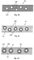
- FIG. 2a to 2d is an example of an embodiment of a manufacturing method of the optically variable element 10 according to the Fig. 1a to 1d shown.
- a first intersection point is supplied by a first container 81 with a first fluid, for example ferrofluid 100, in particular a first dispersion with magnetic particles 104.
- a second fluid in particular a second dispersion, in the present case a coloring pigment dispersion 120 'with a large number of magnetically non-alignable particles, is supplied to the first intersection point 40.
- the first dispersion and second dispersion have a different surface tension and are immiscible.
- the first fluid is hydrophobic and the second fluid is hydrophilic.
- a first emulsion 41 is formed from the first and second dispersion.
- a feed geometry determines, for example, a nozzle for combining the first or second dispersion, their feed rates, viscosities and / or temperature, whether the first fluid or the first second fluid forms the dispersion medium or the disperse phase of the first emulsion 41.
- the first emulsion 41 thus comprises a two-phase mixture of the first fluid and the second fluid.
- the first emulsion 41 is supplied via a first connection, in the present case a first chip, to a second crossing point 50.
- the first connection On the first emulsion 41 facing wall has a surface tension, which is compatible with the dispersion medium of the first emulsion 41. That is, the dispersion medium of the first emulsion 41 has hydrophilic properties, and the corresponding wall of the first compound also has hydrophilic properties, or vice versa.
- the dispersion medium of the first emulsion 41 see Fig. 2b As the dispersion medium, the hydrophilic pigment dispersion 120 'having magnetically non-alignable particles and the disperse phase hydrophobic ferrofluid 100.
- the dispersion medium in the first emulsion 41 forms.
- the fluid with incompatible surface tension comes into contact with the wall and thus is not completely surrounded by the other fluid.
- the first emulsion 41 is supplied with a third fluid 52, for example a polymer.
- a second emulsion 51 is formed from the first emulsion 41 and the third fluid 52.
- the third fluid 52 is in the present example a capsule wall material for forming a capsule wall, in particular the optically variable capsule according to the Fig. 1a-d ,
- the third fluid 52 is presently a photopolymerizable fluid, for. As acrylate, and has hydrophobic properties.
- a feed geometry such as a nozzle for combining the first emulsion 41 with the third fluid 52, their feed rates, viscosities and / or temperature at the second crossover point 50 determines whether the first emulsion 41 or the third fluid 52 is the dispersion medium or the disperse Phase of the second emulsion 51 forms.
- the second emulsion 51 thus comprises the first emulsion 41 and from the first emulsion third fluid 52 is a multiphase mixture, wherein the first emulsion 41 forms a multi-shell emulsion.
- the second emulsion 51 is supplied via a second connection (second chip) to a third intersection point 60.
- the second compound has a surface tension on the wall facing the second emulsion 51 which is compatible with the dispersion medium of the second emulsion 51. That is, the dispersion medium of the second emulsion 51 has hydrophilic properties, and the corresponding wall of the second compound also has hydrophilic properties, or vice versa.
- the dispersion medium of the second emulsion 51 (see Fig. 2c ) hydrophobic properties and the disperse phase of the second emulsion 51 have hydrophilic properties (due to hydrophilic dispersion medium of the first emulsion 41).
- the corresponding wall of the second compound thus has hydrophobic properties.
- phase (first emulsion 41 or third fluid 52) having a surface tension compatible with the second emulsion 51 forms the dispersion medium in the second emulsion 51.
- the incompatible surface tension phase is prevented from contacting the wall and thus not being completely surrounded by the other phase (first emulsion 41 or third fluid 52).
- the surface tension of the third fluid 52 may be selected such that either the first fluid or the second fluid is preferentially wetted by the third phase. Preferably, however, it wets and surrounds third phase, the dispersion medium of the first emulsion 41. In the present case, the third fluid 52 surrounds the first emulsion 41st
- a fourth fluid 62 is fed to the second emulsion 51.
- a third emulsion 61 is formed from the second emulsion 51 and the fourth fluid 62.
- the fourth fluid 62 is an external carrier fluid in the present example.
- the fourth fluid 62 has a surface tension which is not compatible with the dispersion medium of the second emulsion 51.
- the fourth fluid is a hydrophilic outer carrier liquid, in the present case water.
- a feed geometry such as a nozzle for combining the second emulsion 51 with the fourth fluid 62, their feed rates, viscosities and / or temperature at the third intersection point 60, whether the second emulsion 51 or the fourth fluid 62, determines the dispersion medium or the disperse Phase of the third emulsion 61 forms.
- the third emulsion 61 thus comprises a multiphase mixture of the second emulsion 51 and the fourth fluid 62, the second emulsion 51 forming a multi-shell emulsion.
- the third emulsion 61 is supplied to a discharge container 70 via a third connection (third chip).
- the third compound has a surface tension on the wall facing the third emulsion 61 which is compatible with the dispersion medium of the third emulsion 61. That is, the dispersion medium of the third emulsion 61 has hydrophilic properties, and the corresponding wall of the third compound also has hydrophilic properties, or vice versa.
- the associated wall of the third compound has correspondingly hydrophilic properties.
- phase (second emulsion 51 or fourth fluid 62) having a compatible surface tension of the wall facing the third emulsion 61 forms the dispersion medium of the third emulsion 51.
- the incompatible surface tension phase is prevented from contacting the wall and thus not completely surrounded by the other phase (second emulsion 51 or fourth fluid 62).
- the surface tension of the fourth fluid 62 may be selected such that either the third fluid 52 or the second emulsion 51 is wetted by the fourth fluid 62.
- the fourth fluid 62 wets and surrounds the dispersion medium of the second emulsion 51.
- the third emulsion 61 is a multi-shell emulsion.
- the multi-shell emulsion comprises particulate, preferably drop-shaped, the first emulsion 41, which is surrounded by the third fluid 52 and forms the second emulsion 51, which in turn is surrounded by the fourth fluid 62.
- the third emulsion 61 After the third emulsion 61 is formed, it is exposed to UV light according to the exemplary embodiment, as a result of which the third fluid 52 crosslinks.
- a capsule wall is formed which surrounds the second emulsion 51.
- a source of energy for UV light is particularly suitable a focused LED UV emitter.
- a focused LED UV emitter instead of or in addition to UV light, other methods of forming the capsule wall, e.g. B. thermal loading, conceivable.
- An encapsulated particle of the third emulsion 61 constitutes an optically variable element 10.
- the optically variable elements 10 formed in the third emulsion 61 are supplied to the output container 70 in the outer carrier liquid 62.
- a first, second and / or third emulsion 41, 51, 61 having a uniform, reproducible size of the particles of the respective disperse phase is possible.
- an auxiliary capsule wall is formed between the first and second fluid after or before mixing at the first crossing point 40.
- the material of the auxiliary capsule wall has a surface tension that is compatible with the surface tension of the enveloping first or second fluid, such as coloring pigment dispersion 110 or ferrofluid 104.
- the auxiliary capsule wall is destroyed, particularly preferably decomposed, for example by means of UV radiation, lasers and / or electron beams.
- the auxiliary capsule wall can be designed to be soluble in the enveloping first or second dispersion, so that the auxiliary capsule wall dissolves, for example after a certain period of time and / or by means of the introduction of temperature.
Landscapes
- Physics & Mathematics (AREA)
- Health & Medical Sciences (AREA)
- General Health & Medical Sciences (AREA)
- Toxicology (AREA)
- General Physics & Mathematics (AREA)
- Spectroscopy & Molecular Physics (AREA)
- Credit Cards Or The Like (AREA)
- Electrochromic Elements, Electrophoresis, Or Variable Reflection Or Absorption Elements (AREA)
- Inks, Pencil-Leads, Or Crayons (AREA)
- Printing Methods (AREA)
Abstract
Description
- Die vorliegende Erfindung betrifft ein optisch variables Element zur Anordnung an einem Datenträger, insbesondere Wertgegenstand wie Wertdokument, einen Datenträger mit einem optisch variablen Sicherheitselement und einer Herstellungsverfahren eines optisch variablen Elements.
- Optisch variable Elemente werden zu Gestaltungszwecken, aber auch in einem und/ oder als Echtheitsmerkmal eingesetzt. Ein derartiges Echtheitsmerkmal, auch als Sicherheitsmerkmal bezeichnet, kann beispielsweise eine besondere optische Wiedergabe in Abhängigkeit des Betrachtungswinkels, wie z. B. ein Hologramm, aufweisen. Weiterhin sind Änderungen der optischen Wiedergabe bzw. des optischen Eindrucks aufgrund veränderter physikalischer oder chemischer Bedingungen und Umwelteinflüsse denkbar, beispielsweise aufgrund thermischer Beeinflussung. Weiterhin ist eine veränderliche optische Wiedergabe aufgrund magnetischer Beaufschlagung bekannt.
- Bisherige optisch variable Elemente, welche aufgrund magnetischer Beaufschlagung bekannt sind, umfassen ein plättchenförmiges optisch variables mit Magnetit beschichtetes Pigment, welches mit einer umhüllenden Flüssigkeit verkapselt in einer Kapsel vorliegt. In Aufsicht ohne Magnetfeld ist ein wolkiger bzw. uneinheitlicher Farbeindruck in Abhängigkeit der Lagen der plättchenförmigen Pigmente in der Kapsel sichtbar. Bei Anlegen eines Magnetfelds richten sich diese Plättchen entsprechend den magnetischen Feldlinien aus. Die geringfügige Lageveränderung der plättchenförmigen magnetisch orientierbaren Pigmente führt zwangsläufig zu geringen optischen Kontrasten. Zudem kann das plättchenförmige beschichtete Pigment in der Kapsel verklemmen.
- Es ist demnach eine Aufgabe der Erfindung, ein magnetisch schaltbares optisch variables Element bereitzustellen, wobei ein Erkennungskontrast in der Fläche sichtbar ist.
- Diese Aufgabe wird mit den Merkmalen der unabhängigen Ansprüche gelöst. Besonders vorteilhafte Ausgestaltungen sind Gegenstand der abhängigen Ansprüche.
- Erfindungsgemäß wird die Aufgabe durch ein optisch variables Element zur Anordnung an einem Datenträger gelöst. Das optisch variable Element umfasst eine erste Phase mit einem ersten Fluid, welches ein magnetisch ausrichtbares Pigment umfasst und eine erste Farbgebung aufweist. Weiterhin umfasst das optisch variable Element eine zweite Phase mit einem zweiten Fluid. Das zweite Fluid weist magnetisch nichtausrichtbare Eigenschaften mit einer zweiten Farbgebung auf. Die erste und zweite Phase weisen eine unterschiedliche Oberflächenspannung auf und sind daher miteinander nicht mischbar. Die erste und zweite Phase sind von einer Kapsel umgeben. Im weiteren Verlauf ist diese Kapsel auch als optisch variable Kapsel bezeichnet.
- Das zweite Fluid kann ein magnetisch nichtausrichtbares Pigment aufweisen oder als magnetisch nichtausrichtbares Pigment ausgebildet sein. Das zweite Fluid ist im Wesentlichen unmagnetisch ausgebildet. Dabei kann das Material des zweiten Fluids, insbesondere des magnetisch nichtausrichtbaren Pigments, aus unmagnetischem Werkstoff ausgebildet sein. Weiterhin kann das Material des zweiten Fluids, insbesondere des magnetisch nichtausrichtbaren Pigments, aus magnetischem Werkstoff ausgebildet sein, jedoch derart beschaffen sein, dass es sich in einem magnetischen Feld nicht bzw. kaum ausrichtet. Dies ist beispielsweise der Fall, wenn eine magnetische Beschichtung und/ oder ein Kern (Teil des Pigments) sehr gering im Verhältnis zu dem nichtmagnetischen Teil des zweiten Fluids ist.
- Das magnetisch ausrichtbare Pigment weist ein magnetisierbares Material auf. Das magnetisierbare Material weist zumindest in Anwesenheit eines magnetischen Feldes ein magnetisches Moment auf und ist in diesem Zustand magnetisch ausgebildet. Das magnetisch ausrichtbare Pigment orientiert sich hinsichtlich seiner Nord-Süd-Richtung entlang der Magnetfeldlinien. Vorzugsweise weist das magnetisch ausrichtbare Pigment paramagnetische, insbesondere superparamagnetische, Eigenschaften auf. Das heißt, das magnetisch ausrichtbare Pigment weist in Abwesenheit eines magnetischen Feldes kein oder ein sehr geringes magnetisches Moment auf, so dass das magnetisch ausrichtbare Pigment vorzugsweise nicht magnetisch ausgebildet ist.
- Im Rahmen dieser Erfindung wird unter dem Ausrichten eines Elements in einem Magnetfeld sowohl eine Orientierung als auch eine Positionierung entsprechend dem Magnetfeld verstanden. Wie bereits dargelegt handelt es sich bei der Orientierung um eine Anordnung in Nord-Süd-Richtung entlang der Magnetfeldlinien aufgrund des magnetischen Moments. Eine Positionierung ist durch eine ortsbezogene Bezugnahme, beispielsweise eine Ortsveränderung und/ oder der Einnahme einer Ortsposition, gekennzeichnet.
- Bevorzugt sind die magnetischen Pigmente so stabilisiert, dass diese ohne Beaufschlagen mit magnetischem Feld, insbesondere nach Entfernen und/ oder Abschalten einer Magnetfeldquelle in ihrer Phase weder aggregieren noch sedimentieren.
- Mit der erfindungsgemäßen Lösung wird ein optisch variables Element bereitgestellt, womit in magnetischem Feld das erste Fluid mit dem magnetisch ausrichtbaren Pigment ausgerichtet wird. Insbesondere wird im magnetischen Feld, beispielsweise bei Verwendung der Magnetfeldquelle, z. B. ein Magnet, an einer ersten Seite des optisch variablen Elements, vorzugsweise der optisch variablen Kapsel, das erste Fluid mit dem magnetisch ausrichtbaren Pigment mit der ersten Farbgebung von einer Magnetfeldquelle angezogen und entsprechend nahe der Magnetfeldquelle an der ersten Seite des optisch variablen Elements positioniert. Weiterhin wird das magnetisch ausrichtbare Pigment im Rahmen seines magnetischen Moments entsprechend der Magnetfeldlinien orientiert. Das zweite Fluid mit dem beispielsweise magnetisch nichtausrichtbare Pigment hingegen ist im optisch variablen Element, vorzugsweise der optisch variablen Kapsel, im Wesentlichen von dem ersten Fluid verdrängt und entfernt von der Magnetfeldquelle an einer zweiten Seite angeordnet bzw. positioniert. Bei Betrachtung des optisch variablen Elements auf eine der Magnetfeldquelle gegenüberliegender Seite (zweite Seite) ist lediglich die zweite Farbgebung sichtbar.
- Wird die Magnetquelle an der zweiten Seite angeordnet, richtet sich das erste Fluid entsprechend der Magnetfeldquelle aus. Das erste Fluid verdrängt das zweite Fluid mit z. B. dem magnetisch nichtausrichtbaren Pigment. Das zweite Fluid wird dann im Wesentlichen an der ersten Seite angeordnet.
- Nach Wegnahme des Magneten bleibt vorzugsweise die Positionierung des ersten und zweiten Fluids erhalten. Somit bleibt auf der ersten und zweiten Seite zumindest bis zu einer Neuorientierung mittels Magnetfeld der Farbeindruck der ersten und zweiten Seite erhalten und die erste und zweite Farbgebung sichtbar.
- Ein Datenträger im Sinne der Erfindung ist grundsätzlich als Gegenstand zur Wiedergabe von Informationen zu verstehen, insbesondere ein Wertdokument. Unter Wertdokumenten werden dabei blattförmige Gegenstände verstanden, die beispielsweise einen monetären Wert oder eine Berechtigung repräsentieren und daher nicht beliebig durch Unbefugte herstellbar sein sollen. Sie weisen daher nicht einfach herzustellende, insbesondere zu kopierende, Merkmale auf, deren Vorhandsein ein Indiz für die Echtheit, d.h. die Herstellung durch eine dazu befugte Stelle, ist. Wichtige Beispiele für solche Wertdokumente sind Chipkarten, Coupons, Gutscheine, Schecks und insbesondere Banknoten. Mithilfe des Datenträgers soll insbesondere visuell eine Information wiedergegeben werden, welche von einem besonderen Wert ist und vorzugsweise mit einem Echtheitsmerkmal bzw. Sicherheitselement versehen werden soll. Gleichzeitig kann das Sicherheitselement zumindest Teil der Information sein.
- Die erste und/ oder zweite Farbgebung kann mithilfe einer Pigmentierung ausgebildet sein. Beispielsweise kann die Pigmentierung lumineszierende Eigenschaften umfassen und beispielsweise Licht mit Wellenlängen im sichtbaren Spektrum emittieren. Weiterhin kann die Pigmentierung eine Emission von Licht im infraroten oder ultravioletten Spektrum aufweisen.
- Weiterhin kann die Pigmentierung Licht im UV-, Vis,- und/ oder IR-Bereich absorbieren. Darüber hinaus kann die Pigmentierung Licht im längerwelligen Bereich absorbieren und/ oder im kürzerwelligen Bereich des Spektrums emittieren (Anti-Stokes).
- In einer bevorzugten Ausführungsform umfasst die optisch variable Kapsel ein Trägerfluid. Das Trägerfluid ist vorzugsweise eine Trägerflüssigkeit. Das Trägerfluid kann die erste und zweite Phase umfassen. Weiterhin kann die erste Phase oder die zweite Phase das Trägerfluid bilden.
- Weiterhin können die erste Phase und/ oder die zweite Phase als Dispersion ausgebildet sein, wobei das Trägerfluid das Dispersionsmittel der ersten oder zweiten Phase bildet und die zweite oder erste Phase die dispergierte Phase bildet.
- Vorzugsweise weisen die erste und/ oder zweite Phase eine Oberflächenspannung auf, welche kompatibel zur Oberflächenspannung des Dispersionsmittel ist, wodurch ein Benetzen der ersten und/ oder zweiten Phase durch das Trägerfluid möglich ist. Insbesondere kann vorgesehen sein, dass die erste Phase und zweite Phase unterschiedliche Oberflächenspannung aufweisen, so dass die erste und zweite Phase miteinander nicht mischbar ausgebildet sind und unterschiedliche, getrennte Phasen bilden. Beispielsweise ist die erste Phase hydrophob und die zweite Phase hydrophil, oder umgekehrt, ausgebildet.
- In einer Ausführungsform ist die Wand der optisch variablen Kapsel und/ oder eine die erste Phase und/ oder die zweite Phase umhüllende Trennschicht halbtransparent ausgebildet. Aufgrund der Halbtransparenz ist eine durchscheinende Farbgebung der ersten oder zweiten Phase gewährleistet, wobei gleichzeitig Unschärfeneffekte verhindert und eine farblich deckende Wiedergabe ermöglicht werden. Der Grad der Unschärfe ist so einzustellen, dass eine zu große Kontrastreduzierung durch die Unschärfe bzw. Streuung verhindert wird. In einer bevorzugten Ausführungsform ist die Wand der optisch variablen Kapsel und/ oder die Trennschicht transparent ausgebildet, wodurch eine uneingeschränkte und nichttransformierte Wiedergabe der Farbgebung möglich ist.
- In einer Ausführungsform kann vorgesehen sein, dass das erste Fluid, insbesondere das magnetisch ausrichtbare Pigment, Magnetit, insbesondere Nanomagnetit, vorzugsweise eine Vielzahl an aggregierte nicht- geordnete bzw. orientierte Nanomagnetite, Eisen, und/ oder Kobalt umfasst. Dabei kann das erste Fluid eine Kombination aus Nanomagnetite und Eisen, beispielsweise aufgrund einer Oxidation von Nanomagnetit von Fe3O4 zu Fe2O3 aufweisen. Insbesondere kann vorgesehen sein, dass die erste Phase bzw. das erste Fluid als Ferrofluid ausgebildet ist. Das magnetisch ausrichtbare Pigment, insbesondere die erste Phase, weist vorzugsweise eine sehr geringen bis keine Remanenz auf. Vorzugsweise umfasst das magnetisch ausrichtbare Pigment, wenigstens das erste Fluid eine Dispersion mit magnetischen Nanopartikeln, typischerweise von 2 bis 50 nm, welche in einem Dispersionsmedium kolloidal suspendiert sind.
- In einer weiteren Ausführungsform ist die Rheologie insbesondere die Viskosität der Trägerflüssigkeit bzw. ersten Phase oder zweiten Phase temperaturabhängig. Das heißt, dass bei höherer Temperatur die Viskosität geringer wird. In einer besonderen Ausführungsform ändert sich bei Temperaturerhöhung der Aggregatszustand der Trägerflüssigkeit bzw. ersten Phase oder zweiten Phase von fest nach flüssig. In diesem Fall ist die Schaltbarkeit des optisch variablen Elements nur bei erhöhter Temperatur in Gegenwart eines äußeren Magneten möglich. In einer weiteren Ausführungsform ist auch eine Kombination von optisch variablen Elementen als Figuren, Zeichen und/ oder Flächenteile mit Trägerflüssigkeiten, welche vorzugsweise eine unterschiedliche temperaturabhängige Viskosität aufweisen, vorgesehen. Diese Figuren, Zeichen und/ oder Flächenteile können als Druck auf Basis von Farben, welche die optisch variable Kapsel umfassen, bereitgestellt sein.
- Insbesondere ist vorgesehen, dass die erste Phase und die zweite Phase innerhalb der optisch variablen Kapsel beweglich angeordnet sind. Es ist möglich, dass die erste Phase sich in Anwesenheit einer Magnetfeldquelle in dessen Richtung und/ oder in Richtung des magnetischen Feldes orientiert und positioniert. Im Wesentlichen positioniert sich die erste Phase zur Magnetfeldquelle, vorzugweise Magnet, hin. Entsprechend wird die zweite Phase von der ersten Phase verdrängt und in einer Position im Wesentlichen entfernt der Magnetfeldquelle angeordnet.
- Vorzugsweise gibt die Seite des optisch variablen Elements, welche der Magnetfeldquelle nahe liegt, entsprechend in Abhängigkeit des magnetischen Feldes und einer Position der Magnetfeldquelle im Wesentlichen die zweite Farbgebung wieder.
- In einer Ausführungsform kann vorgesehen sein, dass die Farbgebung der ersten Phase zur Farbgebung der zweiten Phase einen großen Farbabstand aufweist. Aufgrund eines großen Farbabstands ist ein besonders gut erkennbarer Farbkontrast erkennbar.
- In einer Ausführungsform ist vorgesehen, dass ein optisch variables Element, bestehend aus optisch variablen Kapseln bei Betrachtung einer Seite und/ oder eines Punkts einer Seite unabhängig vom Betrachtungs- oder Beleuchtungswinkel einen gleichen bzw. ähnlichen Farbton aufweist. Insbesondere ist die zu betrachtende Seite als die Seite definiert, an welcher eine Ausrichtung der ersten oder zweiten Phase. Die erste Phase und/ oder zweite Phase ist im Wesentlichen dreidimensional, vorzugsweise sphärisch, besonders bevorzugt im Wesentlichen kugelförmig, ausgebildet. Da die erste Phase mit erster Farbgebung sich während und nach dem Beaufschlagen mit magnetischem Feld auf der Seite der Kapsel positioniert, welche nahe der Magnetfeldquelle ist und die zweite Phase mit zweiter Farbgebung sich an gegenüberliegender Seite entsprechend positioniert, ist unabhängig vom Betrachtungswinkels auf diese beiden Seiten (0°-180°) und/ oder der Beleuchtung die erste oder zweite Farbgebung deckend erkennbar.
- Vorzugsweise weist das erste Fluid bzw. die erste Phase superparamagnetische Eigenschaften auf. Nach dem Beaufschlagen der erste Phase mit magnetischem Feld, insbesondere nach Wegnahme oder Abschalten des magnetischen Feldes, verbleibt keine Remanenz, so dass ein erneutes Ausrichten der erste Phase in der optisch variablen Kapsel, ohne dass besondere Entmagnetisierungsverfahren durchgeführt werden, möglich ist.
- In einer Ausführungsform kann das optisch variable Element, insbesondere das magnetisch ausrichtbare Pigment bzw. die erste Phase, das magnetisch nichtausrichtbare Pigment bzw. die zweite Phase und/ oder die optisch variable Kapsel, insbesondere ein Teil davon, beispielsweise die Kapselwand, ein Effektpigment, insbesondere ein IR-, UV- und/ oder ein Lumineszenzpigment umfassen. Besonders bevorzugt ist eine Beschichtung der magnetisch ausrichtbaren Pigmente und/ oder das magnetisch nichtausrichtbare Pigment mit voran genannten Effektpigmenten. Die Effektpigmente können auch Farbstoffe sein. Insbesondere durch ein derartiges Effektpigment ist eine maschinenlesbare Auswertung und Erkennung des optisch variablen Elements erweitert und damit sicherer. Die magnetisch ausrichtbaren Pigmente bzw. das erste Fluid und/ oder das magnetisch nichtausrichtbare Pigment bzw. das zweite Fluid können gleichartige, gleiche oder unterschiedliche Effektpigmente aufweisen, so dass die Echtheit des optisch variablen Elements aufgrund der Übereinstimmung zwischen dem optisch variablen Element und Umfeld geprüft werden kann. Anstatt oder zusätzlich zum Effektpigment kann ein Effektfarbstoff verwendet werden. Unter Effektpigment und/ oder Effektfarbstoff werden Stoffe verstanden, welche fluoreszierende und/ oder phosphoreszierende Eigenschaften aufweisen und/ oder welche Anti-Stokes und/ oder IR-absorbierende Eigenschaften aufweisen.
- In einer weiteren Ausführungsform ist im Umfeld des optisch variablen Elementes mindestens ein erster, besonders bevorzugt beide Farbzustände (erste und zweite Farbgebungen) und/ oder soweit vorhanden beide Effektzustände als Referenzfeld angeordnet. Eine Überprüfung des optisch variablen Elements sowohl ohne als auch mit Hilfsmittel (auch maschinell) wird besonders einfach ermöglicht.
- In einer Ausführungsform umfasst die erste Phase einen farbgebenden Bereich zur Wiedergabe der ersten Farbgebung. Der farbgebende Bereich kann einen Farbstoff, vorzugsweise Ruß und/ oder organische Buntpigmente, umfassen. Weiterhin kann der farbgebende Bereich einen Farbfilter, beispielsweise mittels Beschichtung und/ oder auf atomarer Ebene, beispielsweise mittels Brechung am Atomgitter, aufweisen. Der farbgebende Bereich kann die erste Phase, das erste Fluid und/ oder das magnetisch ausrichtbare Pigment umgeben, vorzugsweise umhüllen.
- In einer Ausführungsform können die erste und zweite Phase derart angeordnet sein, dass die zweite Phase die erste Phase umgibt, vorzugsweise umhüllt. Die erste Phase ist demnach von der zweiten Phase umschlossen, wobei sich vorzugsweise eine Trennschicht, beispielsweise eine Trennwand und/ oder eine Subkapselwand ausbildet.
- In einer bevorzugten Ausführungsform kann die erste Phase, insbesondere das erste Fluid, verkapselt mit einer vorzugsweise löslichen funktionelle-Beschichtung und/ oder funktionelle Partikel ausgebildet sein. Die Beschichtung bzw. die funktionellen Partikel können zumindest temporär eine Trennwand, vorzugsweise eine Hilfskapsel, um das magnetisch ausrichtbare Pigment bilden, wobei die Beschichtung bzw. die funktionellen Partikel, d.h. vorzugsweise die Hilfskapsel innerhalb des die Hilfskapsel umgebenden zweiten Fluids, aufgelöst bzw. zerstört werden können. Selbst nach der Auflösung können die funktionelle Beschichtung bzw. die funktionellen Partikel zumindest partikulär ausgebildet bleiben. Weiterhin können die magnetisch ausrichtbaren Pigmente, insbesondere magnetische Partikel der magnetisch ausrichtbaren Pigmente, beispielsweise magnetische Nanopartikel, eine vorzugsweise farbgebende Beschichtung aufweisen.
- In einer Ausführungsform ist die optisch variable Kapsel hinsichtlich der Größe vorzugsweise als Mikrokapsel, vorzugsweise mit einem mittleren Durchmesser von 6-50 µm ausgebildet. Weiterhin kann die optisch variable Kapsel im Bezug zur Größe, insbesondere räumlichen Ausdehnung zum magnetisch ausrichtbaren Pigment bzw. ersten Phase ausgebildet sein, wobei vorzugsweise die erste Phase Pigmente umfasst, welche einen mittleren Durchmesser von weniger als 3 µm, insbesondere weniger als 1 µm. Die optisch variable Kapsel kann eine oder mehrere erste und/ oder zweite Phasen, welche unterschiedlich zueinander ausgebildet sind, umfassen.
- In einer Ausführungsform gemäß der Erfindung kann das optisch variable Element und gegebenenfalls das optisch variable Sicherheitselement an einem Datenträger, insbesondere Ausweisdokument und/ oder Wertdokument angeordnet sein.
- In einer Ausführungsform gemäß der Erfindung kann das optisch variable Element und gegebenenfalls das optisch variable Sicherheitselement an einem Datenträger, insbesondere Ausweisdokument und/ oder Wertdokument angeordnet sein.
- Damit das optisch variable Element, insbesondere das Sicherheitselement bereits bei dessen Auslieferung eine bestimmte Wiedergabe aufweist, insbesondere dass bei Verwendung einer Vielzahl von optisch variablen Elemente eine gleiche oder zumindest ähnliche Wiedergabe aufweisen, kann das optisch variable Element, insbesondere Sicherheitselement bei der Herstellung, oder nach der Herstellung, beispielsweise in einer Druckmaschine, bei einer Qualitätskontrolle bei einer Prüfeinrichtung des optisch variablen Elements beispielsweise in einer Wertdokumenteprüfvorrichtung, insbesondere Sicherheitselements, und/ oder bei einer Eingabe - und/ oder Ausgabevorrichtung von Wertdokumenten, beispielsweise in einem Ausgabeterminal, vororientiert und vorpositioniert werden.
- Bei einem Verfahren zur Herstellung eines optisch variablen Elements gemäß der Erfindung wird in einem Schritt ein erstes Fluid (erste Phase) bereitgestellt. Das erste Fluid weist eine Dispersion mit magnetischen Partikeln, vorzugsweise Ferrofluid, auf. Das erste Fluid, vorzugsweise das magnetisch ausrichtbare Partikel weist eine erste Farbgebung auf. Weiterhin wird ein zweites Fluid (zweite Phase), welches nicht mischbar zum ersten Fluid ist, bereitgestellt. Das zweite Fluid weist eine zweite Farbgebung auf. Vorzugsweise weist das zweite Fluid Farbpigmente auf, wobei das zweite Fluid besonders bevorzugt als Dispersion von Farbpigmenten ausgebildet ist. Weiterhin kann das zweite Fluid einen Farbstoff zur Wiedergabe der zweiten Farbgebung aufweisen.
- Das erste Fluid und das zweite Fluid bilden erfindungsgemäß in einem weiteren Schritt eine erste Emulsion. Dabei bildet entweder das erste Fluid das Dispersionsmittel und das zweite Fluid die disperse Phase oder das zweite Fluid das Dispersionsmittel und das erste Fluid die disperse Phase. Welches Fluid das Dispersionsmittel bildet, hängt beispielsweise von der Mischstelle, der jeweiligen Viskosität und/ der jeweiligen Strömungsgeschwindigkeit zum Bilden der ersten Emulsion ab.
- In einem weiteren Schritt wird ein drittes Fluid mit der ersten Emulsion vermengt, wobei das dritte Fluid nicht mischbar zur ersten Emulsion, insbesondere zum Dispersionsmittel der ersten Emulsion ausgebildet ist. Es wird eine zweite Emulsion gebildet, wobei die erste Emulsion als Dispersionsmittel der zweiten Emulsion und das dritte Fluid als disperse Phase der zweiten Emulsion vorliegt, oder das dritte Fluid als Dispersionsmittel der zweiten Emulsion und das Dispersionsmittel der ersten Emulsion als disperse Phase der zweiten Emulsion vorliegt. Ob das dritte Fluid oder die erste Emulsion das Dispersionsmittel bzw. die disperse Phase bildet, hängt beispielsweise von der Mischstelle, der jeweiligen Viskosität und/ der jeweiligen Strömungsgeschwindigkeit zum Bilden der zweiten Emulsion ab.
- In einem weiteren Schritt wird ein viertes Fluid bereitgestellt, wobei das vierte Fluid nicht mischbar zur zweiten Emulsion, insbesondere nicht mischbar zum Dispersionsmittel der zweiten Emulsion ausgebildet ist. Das vierte Fluid und die zweite Emulsion bilden eine dritte Emulsion. Das vierte Fluid bildet das Dispersionsmittel der dritten Emulsion und das Dispersionsmittel der zweiten Emulsion bildet die disperse Phase der dritten Emulsion. Insbesondere dient das vierte Fluid als Trägerfluid der zweiten Emulsion.
- Mit dem erfindungsgemäßen Verfahren wird eine Mehrschalenemulsion gebildet, wobei das magnetisch ausrichtbare Pigment bzw. erste Phase bzw. erste Fluid und/ oder die zweite Phase bzw. das zweite Fluid beweglich angeordnet sind. Durch Beaufschlagen mit einem magnetischen Feld richtet sich das magnetisch ausrichtbare Pigment und somit die erste Phase aus, wobei entsprechend der Ausrichtung und der Aufsichtsrichtung auf das optisch variable Element entweder die Farbgebung des ersten Fluids oder des zweiten Fluids sichtbar ist.
- In einer Ausführungsform des Verfahrens kann vorgesehen sein, dass das Dispersionsmittel der zweiten und/ oder der dritten Emulsion vernetzt wird. Somit findet eine Verkapselung des ersten und/ oder zweiten Emulsion statt. Das optisch variable Element kann einfach und in einem stabilen Zustand transportiert und weiterverarbeitet, beispielsweise als Farbpigment, werden. Das Vernetzen findet beispielsweise durch Energieeintrag, insbesondere mittels Wärme oder ultraviolettem Licht statt. Weiterhin wäre auch eine chemische Reaktion denkbar.
- In einer Ausführungsform kann das erste, zweite, dritte und/ oder vierte Fluid einen Farbstoff, insbesondere ein Farbpigment und/ oder ein Effektpigment bzw. einen Effektfarbstoff umfassen.
- Ein weiteres Herstellverfahren eines optisch variablen Elements gemäß der Erfindung umfasst die Schritte:
- Bereitstellen eines ersten Fluids,
- Verkapseln des ersten Fluids in einer Hilfskapsel,
- Bilden eines ersten Stoffgemisches aus der Hilfskapsel und eines zweiten Fluids,
- Verkapseln des ersten Stoffgemisches durch eine Kapsel; und
- zumindest teilweises Zerstören der Hilfskapsel.
- Zur Herstellung der Hilfskapsel kann aus dem ersten Fluid unter hohen Scherkräften in einem Hilfsfluid, welches eine zum ersten Fluid nichtkompatible Oberflächenspannung aufweist, eine Dispersion gebildet werden. Grundsätzlich wird in Abhängigkeit der Scherkräfte, der Temperatur, der Viskosität und/ oder der Scherzeit die gewünschte Tröpfchengröße und damit eine angestrebte Kapselgröße der optisch variablen Kapsel eingestellt. Die Tröpfchengröße kann durch elektrostatische oder sterische Stabilisierung stabil gehalten werden um eine Oswaldreifung zu vermeiden.
- Der Dispersion wird ein Hilfskapselwandmaterial für die Hilfskapsel zugegeben. Das Hilfskapselwandmaterial weist eine zumindest annähernd kompatible Oberflächenspannung zum ersten Fluid und dem Hilfsfluid auf. Das Hilfskapselwandmaterial legt sich zwischen der Grenzfläche des ersten Fluids und dem Hilfsfluid an. Das Hilfskapselwandmaterial ist vernetzbar, beispielsweise mittels pH-Wert- und/ oder Temperaturänderung des Hilfsfluids, ausgebildet.
- Vorzugsweise wird weiterhin das Hilfsfluid entfernt, beispielsweise die Dispersion mit der Hilfskapsel getrocknet, insbesondere gefriergetrocknet.
- Die Hilfskapsel wird in einem weiteren Schritt in dem zweiten Fluid dispergiert (erstes Stoffgemisch). Das zweite Fluid ist vorzugsweise eine farbige Pigmentdispersion, kann selbstverständlich auch ein anderes farbgebendes Fluid sein.
- Anschließend erfolgt ein Einemulgieren der Dispersion aus zweitem Fluid und Hilfskapsel in eine (äußere) Trägerflüssigkeit. Mithilfe von Scherkräften kann eine gewünschte Tröpfchengröße erreicht werden. Diese Tröpfchen können eine oder eine Vielzahl an Hilfskapseln in Kombination mit und umgeben vom zweiten Fluid umfassen. Die Trägerflüssigkeit weist eine zum zweiten Fluid nicht-kompatible Oberflächenspannung auf.
- Der Emulsion bzw. Dispersion von Trägerflüssigkeit (auch Trägermedium) und Kombination aus Hilfskapsel und zweitem Fluid wird ein Wandbildungsmaterial zugeführt, wobei das Wandbildungsmaterial die Tröpfchen der Emulsion bzw. Dispersion der Kombination aus Hilfskapsel und zweitem Fluid benetzt. Durch Vernetzen des Wandbildungsmaterials ist die Dispersion aus Hilfskapsel und zweitem Fluid in einer optisch variablen Kapsel verkapselt. Anschließend kann eine Trennung der optisch variablen Kapsel von der Trägerflüssigkeit erfolgen und/ oder die Hilfskapsel aufgelöst bzw. zerstört werden.
- Die Hilfskapsel wird vorzugsweise mittels (äußeren) Energieeintrag zumindest teilweise, vorzugsweise vollständig, zerstört, beispielsweise Elektronenstrahlen und/ oder Licht. Weiterhin kann ein thermischer (z. B. Erwärmung) und/ oder mechanischer (z. B. Ultraschall) Energieeintrag und/ oder ein chemische Reaktion, beispielsweise ein definiertes Auflösen der Hilfskapselwand im ersten Stoffgemisch. Beispielsweise kann die Hilfskapselwand eine zeitlich begrenzte Stabilität aufweisen, z.B. eine Hilfskapselwand aus Gelatine bei einem wässerigen Trägerfluid.
- Vorzugsweise existiert die Hilfskapsel nur temporär und wird erst nach Erstellung der (End-)Kapsel aufgelöst.
- Vorzugsweise ist das Material der Hilfskapselwand transparent ausgebildet.
- Die erfindungsgemäße optisch variable Kapsel umfasst ein Mehrphasensystem, wobei eine Phase die erste Phase bzw. das erste Fluid mit magnetisch ausrichtbarem Pigment ausgebildet ist. Diese Phase ist besonders bevorzugt als magnetorheologische Flüssigkeit ausgebildet.
- Das erste Fluid umfasst wenigstens ein magnetisch ausrichtbares Pigment, vorzugsweise Ferrofluid, mit einer ersten Farbgebung. Im Rahmen dieser Erfindung bildet das erste Fluid die erste Phase des optisch variablen Elements. Das zweite Fluid ist vorzugsweise eine farbige Pigmentdispersion mit einer zweiten Farbgebung. Im Rahmen dieser Erfindung bildet die farbige Pigmentdispersion die zweite Phase des optisch variablen Elements. Selbstverständlich kann die farbige Pigmentdispersion auch als Farbstofflösung vorliegen.
- Der Datenträger kann das erfindungsgemäße optisch variable Element und/ oder gegebenenfalls das optisch variable Sicherheitselement aufweisen. In einer Ausgestaltung kann der Datenträger ein Verifikationselement umfassen. Das Verifikationselement weist einen Bereich mit magnetischen Eigenschaften auf, d.h., der Bereich ist magnetisch ausgebildet und erzeugt ein magnetisches Feld. Zur Überprüfung des optisch variablen Elements und/ oder gegebenenfalls des optisch variablen Sicherheitselements können diese in die Nähe des magnetischen Bereichs gebracht werden, vorzugsweise in Überlappung. Die magnetisch ausrichtbaren Pigmente richten sich entsprechend dem magnetischen Feld aus.
- Vorzugsweise weist der Datenträger eine Vielzahl an optisch variablen Elemente bzw. eine Vielzahl an optisch variablen Sicherheitselementen, auf, welche bevorzugt ein- oder mehrlagig in einer Matrix angeordnet sind. Bei dem Datenträger handelt es sich vorzugsweise um ein flächiges, blattförmiges Gut. Der magnetische Bereich kann strukturiert ausgebildet sein, beispielsweise in Form eines oder mehrerer Zeichen, einer Figur und/ oder eines Symbols. Wird die Vielzahl an optisch variablen Elemente bzw. die Vielzahl an optisch variablen Sicherheitselementen in Überlappung zum strukturierten magnetischen Bereich angeordnet, richten sich die magnetisch ausrichtbaren Pigmente entsprechend dem durch den magnetischen Bereich erzeugtem Magnetfeld aus. Am Datenträger ist anhand der Vielzahl an optisch variablen Elemente bzw. der Vielzahl an optisch variablen Sicherheitselementen die Struktur des magnetischen Bereichs erkennbar. Selbst nach Entfernen der Vielzahl an optisch variablen Elemente bzw. der Vielzahl an optisch variablen Sicherheitselementen bleibt die Struktur aufgrund des bevorzugt eindeutigen Farbkontrasts erkennbar. Vorzugsweise handelt es sich beim Datenträger um ein Wertdokument, insbesondere eine Banknote. Der Datenträger weist demnach ein Selbstverifikationselement auf. Ein Echtheitselement, welches durch die optisch variablen Elemente bzw. die Vielzahl an optisch variablen Sicherheitselementen gebildet wird, kann durch das am Datenträger gleichzeitig bereitgestelltes Verifikationselement (magnetischer Bereich) von jedem Benutzer geprüft werden.
- Selbstverständlich können alle Eigenschaften, soweit wie sinnvoll, des magnetisch ausrichtbaren Pigments auch auf das erste Fluid gelesen werden, so dass das erste Fluid entsprechend ausgebildet ist.
- Die Erfindung wird im Folgenden noch weiter beispielhaft an Hand der Zeichnungen erläutert. Es zeigen:
- Fig. 1a
- eine schematische Darstellung einer ersten Ausführungsform einer optisch variablen Kapsel gemäß der Erfindung in nichtmagnetisiertem Zustand;
- Fig. 1b
- eine schematische Darstellung der ersten Ausführungsform einer optisch variablen Kapsel gemäß der Erfindung in magnetisiertem Zustand;
- Fig. 1c
- eine schematische Darstellung eines optisch variablen Elements gemäß der Erfindung in nichtmagnetisiertem Zustand;
- Fig. 1d
- eine schematische Darstellung eines optisch variablen Elements gemäß der Erfindung in magnetisiertem Zustand;
- Fig. 1e
- eine Ausführungsform einer Magnetfeldquelle gemäß der Erfindung; und
- Fig. 2a-d
- ein Herstellverfahren eines optisch variablen Elements gemäß der Erfindung.
- Zur Vereinfachung der Lesbarkeit und des Verständnisses der Erfindung werden in den nachfolgenden Figuren und Figurenbeschreibung ähnliche bzw. gleiche Merkmale, insbesondere hinsichtlich ihrer Ausprägung und/ oder Wirkung, soweit möglich mit gleichen Bezugszeichen versehen.
- In der
Figur 1a ist eine Ausführungsform eines optisch variablen Elements 10 anhand einer optisch variablen Kapsel 105 gemäß der Erfindung dargestellt. Das optisch variable Element 10 weist eine zweite Dispersion (vorliegend Pigmentdispersion; zweites Fluid) aus in einer inneren Trägerflüssigkeit 120 angeordneten magnetisch nichtausrichtbare Pigmenten 110 auf. Weiterhin weist das optisch variable Element 10 eine als erste Dispersion ausgebildetes magnetisch ausrichtbare erste Phase bzw. ein erstes Fluid auf. Das erste Fluidumfasst ein Magnetmaterial, vorliegend Ferrofluid 100. Das Ferrofluid 100 umfasst kolloidal suspendierte magnetische Nanopartikel 104. Das erste Fluid (erste Phase) weist aufgrund des Ferrofluids 104 eine erste Farbwiedergabe, nämlich rotbraun auf. Weiterhin kann das erste Fluid Farbpartikel zur Wiedergabe einer bestimmten Farbe umfassen (nicht dargestellt). Die innere Trägerflüssigkeit 120 mit den darin angeordneten magnetisch nichtausrichtbaren Pigmente 110 bilden eine zweite Phase bzw. ein zweites Fluid. - Die erste Dispersion und zweite Dispersion weisen eine unterschiedliche Oberflächenspannung auf. Die erste Dispersion und zweite Dispersion im optisch variablen Element 10 sind miteinander nicht mischbar.
- Wird das optisch variable Element 10 in ein Magnetfeld gebracht, d.h. befindet sich in der Nähe des optisch variablen Elements 10 eine Magnetfeldquelle, beispielsweise ein Magnet 20 (s.
Fig. 1b ), so orientiert sich die erste Phase mit dem Magnetmaterial (Ferrofluid 100) zum Magnet 20 hin. D.h., das Ferrofluid 104 bewegt sich zum Magnet 20 hin und verdrängt die zweite Phase bzw. das zweite Fluid, insbesondere die innere Trägerflüssigkeit 120 mit den magnetisch nichtausrichtbaren Pigmenten 110. Auf der dem Magneten 20 zugewandten Seite des optisch variablen Elements 10 ist entsprechend die Farbwiedergabe des Ferrofluids 100, auf der dem Magneten 20 gegenüberliegender Seite des optisch variablen Elements 10 ist die Farbwiedergabe der magnetisch nichtausrichtbaren Pigmente 110 erkennbar. - Die
Fig.1c zeigt eine Vielzahl an optisch variable Elemente 10 aus denFig. 1a und 1b , angeordnet auf einer ersten Seite 2 eines Substrats 30. Die optisch variablen Elemente 10 sind in einer Druckschicht 31, beispielsweise ein Aufdruck des Substrats 30, angeordnet. DieFig.1d zeigt optisch variable Elemente 10 gemäßFig. 1c bei Beaufschlagung mit einem Magneten 20. - In Bereichen des Aufdrucks 31, an denen der Magnet 20 nicht angeordnet ist, findet kaum bis keine (Neu-) Orientierung des ersten Fluids bzw. des Ferrofluids 100 statt. Bei den optisch variablen Elementen 10, welche bisher noch nicht mit magnetischem Feld beaufschlagt wurden, verbleibt eine im Wesentlichen bisher zufällige Positionierung des Ferrofluids 100 und des zweiten Fluids, insbesondere der magnetisch nichtausrichtbaren Pigmente 110, in der optisch variablen Kapsel 105 im Wesentlichen erhalten. Ist bereits ein optisch variables Element 10, insbesondere eine optisch variable Kapsel 105, anhand eines Magnetfeldes beaufschlagt worden, bleibt im Wesentlichen die Orientierung und Positionierung des magnetisch ausrichtbaren ersten Fluids, d.h. des Ferrofluids 100, und der magnetisch nichtausrichtbaren Pigmente 110 erhalten. Grundsätzlich wäre jedoch eine Beeinflussung der Positionierung des Ferrofluids 100 und der magnetisch nichtausrichtbaren Pigmente 110 durch beispielsweise Energieeintrag möglich. Im Wesentlichen wird jedoch die Positionierung des Ferrofluids 100, und der magnetisch nichtausrichtbaren Pigmente 110, welche nicht durch das Magnetfeld beaufschlagt werden, aufgrund der (Neu-) Ausrichtung der vom Magnetfeld beaufschlagten optisch variablen Elemente 10 nicht beeinflusst.
- Bei den optisch variablen Elementen 10, bei denen bereits eine Ausrichtung des Ferrofluids 100 stattgefunden hat, würde diese in der Regel ohne weitere Beaufschlagung durch das Magnetfeld erhalten bleiben. Somit wäre vorliegend in Aufsicht auf die erste Seite 2 eine schwarze Farbwiedergabe bzw. rot-braune Farbwiedergabe und eine, gemäß dem vorliegenden Beispiel, weiße Farbwiedergabe und in Durchsicht und/ oder Aufsicht auf die zweite Seite 3 eine weiße Farbwiedergabe und eine schwarze bzw. rot-braune Farbwiedergabe erkennbar, in Abhängig der beispielsweise vorhergenannten externen Beeinflussungen und/ oder der Farbwiedergabe und Transparenz des Substrats 30.
- An einer zweiten Oberfläche des Substrats 30, welche der ersten Oberfläche gegenüber liegt, ist in
Figur 1d ein Magnet 20 angeordnet. Das Magnetfeld des Magneten 20 beeinflusst die optisch variablen Elemente 10 in dem Bereich der Druckschicht 31, an dem der Magnet 20 angeordnet ist. D.h., diese optisch variablen Elemente 10 richten sich entsprechend dem Magnet 20 aus, wobei, soweit noch nicht bereits geschehen, sich das Ferrofluid 100 in den optisch variablen Elementen 10 und somit die erste Phase zu der zweiten Seite 3 der optisch variablen Elemente 10 bewegt, welche dem Magnet 20 zugeordnet ist. Die erste Phase würde dann die zweite Phase, insbesondere die in der inneren Trägerflüssigkeit 120 angeordneten magnetisch nichtausrichtbaren Pigmente 110 verdrängen und an der dem Magnet 20 gegenüberliegender Seite des optisch variablen Elements 20 positioniert werden. - In erster Aufsicht (Pfeil A) ist gemäß
Fig.1d der Farbeindruck in der Farbe der Farbpartikel bzw. der magnetisch nichtausrichtbaren Pigmente 110 zu erkennen. In Durchsicht (Pfeil B), d.h. auf die zweite Seite 3, erscheint bei teiltransparentem und/ oder transparentem Substrat 30 die Farbwiedergabe des Ferrofluids 100, so dass vorliegend eine rot-braune bis schwarze Farbe erkennbar ist. - Das Substrat 30 kann ein transparentes, transluzentes, opakes oder im Wesentlichen optisch dichtes Substrat auf Basis von Papier, insbesondere Fasermaterial, vorzugswiese Baumwollfasern, einem Folienmaterial oder einem Komposit von beiden, beispielsweise ein Hybrid-Substrat, sein. Die Druckschicht 31 umfasst eine Matrix, in der die optisch variablen Elemente 10 angeordnet sind. Die Matrix ist beispielsweise ein Bindemittel einer Farbe, insbesondere Druckfarbe, oder eines Lackes und/ oder ein Folie, vorzugsweise Kunststofffolie und/ oder Kunststofffaser, insbesondere ein Faserflies auf Basis der Kunstofffaser. Befindet sich ein Magnet 20 an einer zweiten Seite 3 des Wertdokuments 1, vorliegend dessen Unterseite, im Bereich des Aufdrucks 31 mit dem optisch variablen Element 10, richtet sich das Ferrofluid 100 des optisch variablen Elements 10 aus. D. h., das Ferrofluid 100 positioniert sich in dem optisch variablen Element 10 auf der Seite des Magnets 20. Dabei werden die magnetisch nichtausrichtbaren Partikel 110 der zweiten Phase verdrängt, insbesondere zu Positionen an der dem Magnet 20 gegenüberliegender Seite. In Aufsicht auf die erste Seite 2 (Pfeil A) ist im Bereich des Magnets 20 eine weiße Farbe (Farbe der magnetisch nichtausrichtbaren Partikel 110) erkennbar. In Aufsicht auf die zweite Seite 3 (Pfeil B) bzw. in Durchsicht ist in diesem Bereich eine schwarze Farbe (Farbe des ersten Fluids bzw. des Ferrofluids 100) erkennbar.
- Der Vorteil eines transparenten Substrats 30 liegt darin, dass eine Neuorientierung des ersten Fluids bzw. des Ferrofluids 100 und eine damit verbundene veränderte Farbwiedergabe des Sicherheitselements, d.h. des Aufdrucks 31, sowohl auf der ersten Seite 2 als auch auf der zweiten Seite 3 festgestellt werden kann. Insbesondere kann der Aufdruck 31 hinsichtlich zwei unterschiedlichen Farbwiedergaben geprüft werden. In einer besonderen Ausführungsform ist das transparente Substrat eingefärbt, so dass sich eine Mischfarbe aus dem Zustand des optisch variablen Elements 10 bzw. der Farbe 31 zeigt und somit der Farbeidruck des optisch variablen Elements immer unterschiedlich von der ersten Seite 2 zur zweiten Seite 3 ist.
- In einer Ausführungsform befindet sich zumindest in Teilbereichen auf der Druckschicht 31 und/ oder unterhalb der Druckschicht 31, vorzugsweise bei transparentem Substrat 30 und/ oder auf der zweiten Seite 3, eine optisch variable Farbschicht auf Basis von Interferenzpigmenten. Bei Verwendung von dunkler erster oder zweiter Farbgebung (beispielsweise mit Ferrofluid 100 als erstes Fluid) ist ein besonders guter Farbeffekt in Form eines Colorschifts erkennbar.
- In einer besonders attraktiven Ausführungsform enthält das transparente Substrat 30 zusätzlich visuell nicht sichtbare UV-absorbierende und/ oder IR-absorbierende Stoffe. Dadurch ist es möglich, auf der ersten Seite 2 und zweiten Seite 3 unabhängig vom visuellen Eindruck unterschiedliche Zusatzeigenschaften zu generieren. Beispielsweise weist das magnetisch nichtausrichtbare Pigment 110 eine Fluoreszenzbeschichtung auf. Befindet sich der Magnet 20 bei der zweiten Seite 3, ist bei Aufsicht gemäß Pfeil A auf die erste Seite 2, welche dem Magneten 20 gegenüberliegt, bei Bestrahlung mit UV-Licht eine Fluoreszenz feststellbar. Wird hingegen der Magnet 20 an der ersten Seite 2 angeordnet, ist bei Bestrahlung des Wertdokuments 1, insbesondere der zweiten Seite 3, mit UV-Licht von der zweiten Seite 3 keine Fluoreszenz feststellbar. Somit weisen bei Beaufschlagung mit UV-Licht die erste Seite 2 und zweite Seite 3 einen unterschiedlichen Farbeindruck auf.
- Bei transluzentem oder opakem Substrat 30 dagegen ist für eine Verifizierung der beiden Farbwiedergaben ein Positionswechsel der Magnetfeldquelle, vorliegend des Magneten 20, sinnvoll, bei bis optisch dichtem Substrat 30 notwendig, so dass zum einen Mal die magnetisch ausrichtbaren Pigmente 100 und zum anderen Mal die magnetisch nichtausrichtbaren Pigmente 110 an der ersten Seite 2 sichtbar sind. Erst dann wäre insbesondere eine Beurteilung auf des Aufdrucks 31, insbesondere dessen Farbgebung und dessen Echtheit möglich.
- Anstelle des in den
Fig.1b und1d dargestellten Magneten 20 mit einer im Wesentlichen homogenen, quaderförmigen Struktur, kann gemäßFig. 1e ein Magnet 20' mit strukturierter Oberfläche oder strukturiertem Volumen 201 verwendet werden. Die Strukturierung 201 codiert reliefartig eine Information mit Höhen 202 und Senken 203. Im Bereich der Senken 203 erfährt ein Sicherheitselement, beispielsweise mit dem Aufdruck 31 gemäß denFig.1c und 1d , ein geringeres Magnetfeld, so dass sich in diesem Bereich das Ferrofluid 100 bzw. das die magnetisch ausrichtbaren Pigmente weniger stark bis vorzugsweise nicht ausrichten. Die optisch variablen Kapseln 105 geben entsprechend die Strukturierung 203 des Magneten 20' und somit die codierte Information wieder. - In den
Fig. 2a bis 2d ist beispielhaft eine Ausführungsform eines Herstellungsverfahrens des optisch variablen Elements 10 gemäß denFig. 1a bis 1d dargestellt. Einem ersten Kreuzungspunkt wird von einem ersten Behälter 81 ein erstes Fluid, beispielsweise Ferrofluid 100, insbesondere eine erste Dispersion mit magnetischen Partikeln 104, zugeführt. Weiterhin wird ein zweites Fluid, insbesondere eine zweite Dispersion, vorliegend eine farbgebende Pigmentdispersion 120' mit einer Vielzahl an magnetisch nichtausrichtbare Partikel, dem ersten Kreuzungspunkt 40 zugeführt. Die erste Dispersion und zweite Dispersion weisen eine unterschiedliche Oberflächenspannung auf und sind nicht mischbar. Beispielsweise ist das erste Fluid hydrophob und das zweite Fluid hydrophil. - Am ersten Kreuzungspunkt 40 bildet sich aus der ersten und zweiten Dispersion eine erste Emulsion 41. Unter Anderem bestimmt eine Zuführgeometrie bspw. eine Düse zum Zusammenführen der ersten bzw. zweiten Dispersion, deren Zuführgeschwindigkeiten, Viskositäten und/ oder Temperatur, ob das erste Fluid oder das zweite Fluid das Dispersionsmedium oder die disperse Phase der ersten Emulsion 41 bildet. Die erste Emulsion 41 umfasst somit aus dem ersten Fluid und aus dem zweiten Fluid ein Zweiphasengemisch.
- Die erste Emulsion 41 wird über eine erste Verbindung, vorliegend ein erster Chip, einem zweiten Kreuzungspunkt 50 zugeführt. Die erste Verbindung weist auf der der ersten Emulsion 41 zugewandten Wand eine Oberflächenspannung auf, welche Kompatibel zum Dispersionsmedium der ersten Emulsion 41 ist. D. h., weist das Dispersionsmedium der ersten Emulsion 41 hydrophile Eigenschaften auf, weist die entsprechende Wand der ersten Verbindung ebenfalls hydrophile Eigenschaften auf, oder umgekehrt. Am vorliegenden Beispiel weist das Dispersionsmedium der ersten Emulsion 41 (siehe
Fig. 2b ) als Dispersionsmedium die hydrophile Pigmentdispersion 120' mit magnetisch nichtausrichtbaren Partikeln und als disperse Phase hydrophobes Ferrofluid 100. Aufgrund der Oberflächenspannung der ersten Verbindung wird zusätzlich bestimmt, dass das Fluid, welches eine zur ersten Emulsion 41 zugewandter Wand kompatible Oberflächenspannung aufweist, das Dispersionsmedium in der ersten Emulsion 41 bildet. Insbesondere wird verhindert, dass das Fluid mit nichtkompatibler Oberflächenspannung mit der Wand in Berührung kommt und somit nicht vollständig von dem anderen Fluid umgeben bzw. umhüllt wird. - Am zweiten Kreuzungspunkt 50 wird der ersten Emulsion 41 ein drittes Fluid 52, beispielsweise ein Polymer, zugeführt. Dabei wird aus der ersten Emulsion 41 und dem dritten Fluid 52 eine zweite Emulsion 51 gebildet. Das dritte Fluid 52 ist im vorliegenden Beispiel ein Kapselwandmaterial zur Bildung einer Kapselwand, insbesondere der optisch variablen Kapsel gemäß den
Fig. 1a-d . Das dritte Fluid 52 ist vorliegend ein photopolymerisierbares Fluid, z. B. Acrylat, und weist hydrophobe Eigenschaften auf. Unter Anderem bestimmt eine Zuführgeometrie, bspw. eine Düse zum Zusammenführen der ersten Emulsion 41 mit dem dritten Fluid 52, deren Zuführgeschwindigkeiten, Viskositäten und/ oder Temperatur am zweiten Kreuzungspunkt 50, ob die erste Emulsion 41 oder das dritte Fluid 52 das Dispersionsmedium oder die disperse Phase der zweiten Emulsion 51 bildet. Die zweite Emulsion 51 umfasst somit aus der ersten Emulsion 41 und aus dem dritten Fluid 52 ein Mehrphasengemisch, wobei die erste Emulsion 41 eine Mehrschalenemulsion bildet. - Die zweite Emulsion 51 wird über eine zweite Verbindung (zweiter Chip) einem dritten Kreuzungspunkt 60 zugeführt. Die zweite Verbindung weist auf der der zweiten Emulsion 51 zugewandten Wand eine Oberflächenspannung auf, welche Kompatibel zum Dispersionsmedium der zweiten Emulsion 51 ist. D. h., weist das Dispersionsmedium der zweiten Emulsion 51 hydrophile Eigenschaften auf, weist die entsprechende Wand der zweiten Verbindung ebenfalls hydrophile Eigenschaften auf, oder umgekehrt. Am vorliegenden Beispiel weist das Dispersionsmedium der zweiten Emulsion 51 (siehe
Fig. 2c ) hydrophobe Eigenschaften und die disperse Phase der zweiten Emulsion 51 hydrophile Eigenschaften (wegen hydrophilem Dispersionsmedium der ersten Emulsion 41) auf. Die entsprechende Wand der zweiten Verbindung weist somit hydrophobe Eigenschaften auf. - Aufgrund der Oberflächenspannung der entsprechenden Wand der zweiten Verbindung wird zusätzlich bestimmt, dass die Phase (erste Emulsion 41 oder drittes Fluid 52), welche eine zur zweiten Emulsion 51 zugewandter Wand kompatible Oberflächenspannung aufweist, das Dispersionsmedium in der zweiten Emulsion 51 bildet. Insbesondere wird verhindert, dass die Phase mit nichtkompatibler Oberflächenspannung mit der Wand in Berührung kommt und somit nicht vollständiges von der anderen Phase (erste Emulsion 41 oder drittes Fluid 52) umgeben bzw. umhüllt wird.
- Weiterhin kann die Oberflächenspannung des dritten Fluids 52 gewählt werden, dass entweder das erste Fluid oder das zweite Fluid von der dritten Phase bevorzugt benetzt wird. Vorzugsweise benetzt und umgibt jedoch die dritte Phase das Dispersionsmedium der ersten Emulsion 41. Vorliegend umgibt das dritte Fluid 52 die erste Emulsion 41.
- Am dritten Kreuzungspunkt 60 wird der zweiten Emulsion 51 ein viertes Fluid 62 zugeführt. Am dritten Kreuzungspunkt 60 wird aus der zweiten Emulsion 51 und dem vierten Fluid 62 eine dritte Emulsion 61 gebildet. Das vierte Fluid 62 ist im vorliegenden Beispiel ein äußeres Trägerfluid. Das vierte Fluid 62 weist eine Oberflächenspannung auf, welche nicht-kompatibel zum Dispersionsmedium der zweiten Emulsion 51 ist. Im vorliegenden Beispiel ist das vierte Fluid eine hydrophile äußere Trägerflüssigkeit, vorliegend Wasser. Unter Anderem bestimmt eine Zuführgeometrie, bspw. eine Düse zum Zusammenführen der zweiten Emulsion 51 mit dem vierten Fluid 62, deren Zuführgeschwindigkeiten, Viskositäten und/ oder Temperatur am dritten Kreuzungspunkt 60, ob die zweite Emulsion 51 oder das vierte Fluid 62 das Dispersionsmedium oder die disperse Phase der dritten Emulsion 61 bildet. Die dritte Emulsion 61 umfasst somit aus der zweiten Emulsion 51 und aus dem vierten Fluid 62 ein Mehrphasengemisch, wobei die zweite Emulsion 51 eine Mehrschalenemulsion bildet.
- Die dritte Emulsion 61 wird über eine dritte Verbindung (dritter Chip) einem Ausgabebehälter 70 zugeführt. Die dritte Verbindung weist auf der der dritten Emulsion 61 zugewandten Wand eine Oberflächenspannung auf, welche Kompatibel zum Dispersionsmedium der dritten Emulsion 61 ist. D. h., weist das Dispersionsmedium der dritte Emulsion 61 hydrophile Eigenschaften auf, weist die entsprechende Wand der dritten Verbindung ebenfalls hydrophile Eigenschaften auf, oder umgekehrt. Am vorliegenden Beispiel weist das Dispersionsmedium der dritten Emulsion 61 (siehe
Fig. 2d ) hydrophile Eigenschaften und die disperse Phase der zweiten Emulsion 51 hydrophobe Eigenschaften (wegen hydrophobem Dispersionsmedium (Kapselwandmaterial = drittes Fluid 52) der zweiten Emulsion 51) auf. Die zugehörige Wand der dritten Verbindung weist entsprechend hydrophile Eigenschaften auf. - Aufgrund der Oberflächenspannung der entsprechenden Wand der dritten Verbindung wird zusätzlich bestimmt, dass die Phase (zweite Emulsion 51 oder viertes Fluid 62), welche eine kompatible Oberflächenspannung der zur dritten Emulsion 61 zugewandten Wand aufweist, das Dispersionsmedium der dritten Emulsion 51 bildet. Insbesondere wird verhindert, dass die Phase mit nichtkompatibler Oberflächenspannung mit der Wand in Berührung kommt und somit nicht vollständig von der anderen Phase (zweite Emulsion 51 oder viertes Fluid 62) umgeben bzw. umhüllt wird.
- Weiterhin kann die Oberflächenspannung des vierten Fluids 62 gewählt werden, dass entweder das dritte Fluid 52 oder die zweite Emulsion 51 von dem vierten Fluid 62 benetzt wird. Vorzugsweise benetzt und umgibt jedoch das vierte Fluid 62 das Dispersionsmedium der zweiten Emulsion 51.
- Im Wesentlichen umfasst gemäß dem Ausführungsbeispiel der
Fig. 2a-d die dritte Emulsion 61 eine Mehrschalenemulsion. Die Mehrschalenemulsion umfasst partikelförmig, vorzugsweise tropfenförmig, die erste Emulsion 41, welche von dem dritten Fluid 52 umgeben ist und die zweite Emulsion 51 bildet, welche wiederum von dem vierten Fluid 62 umgeben ist. - Nach dem Bilden der dritten Emulsion 61 wird diese gemäß dem Ausführungsbeispiel mit UV-Licht beaufschlagt, wodurch das dritte Fluid 52 vernetzt. Somit bildet sich eine Kapselwand aus, welche die zweite Emulsion 51 umgibt. Als Energiequelle für UV-Licht eignet sich insbesondere ein fokussierter LED-UV-Strahler. Anstelle oder zusätzlich zum UV-Licht sind andere Verfahren zum Bilden der Kapselwand, z. B. thermisches Beaufschlagen, denkbar. Ein verkapseltes Partikel der dritten Emulsion 61 stellt ein optisch variables Element 10 dar. Die in der dritten Emulsion 61 ausgebildeten optisch variablen Elemente 10 werden in der äußeren Trägerflüssigkeit 62 dem Ausgabebehälter 70 zugeführt.
- Wie dem Aufbau gemäß den
Figuren 2a-d zu entnehmen ist, kann die Größe der "Partikel" in der ersten, zweiten und/ oder dritten Emulsion 41, 51, 61 durch den Volumenstrom, der Viskosität, der Geometrie der Zuführelemente, beispielsweise Düsen, Beschichtungen und/ oder Material von Verbindung zwischen Kreuzungsstellen und Behälter zur Aufnahme von Fluiden, eingestellt werden. Insbesondere ist eine erste, zweite und/ oder dritte Emulsion 41, 51, 61 mit einheitlicher, reproduzierbarer Größe der Partikel der jeweiligen dispersen Phase möglich. - Es kann vorgesehen sein, dass zwischen dem ersten und zweiten Fluid nach oder vor dem Vermengen am ersten Kreuzungspunkt 40 eine Hilfskapselwand ausgebildet wird. Das Material der Hilfskapselwand weist eine Oberflächenspannung auf, welche mit der Oberflächenspannung des umhüllenden ersten oder zweiten Fluids, beispielsweise farbgebende Pigmentdispersion 110 oder Ferrofluid 104, kompatibel ist. Vorzugsweise wird, nachdem die Kapselwand (s.o.) ausgebildet ist, die Hilfskapselwand zerstört, besonders bevorzugt zersetzt, beispielsweise mittels UV-Strahlung, Laser und/ oder Elektronenstrahlen. Weiterhin kann die Hilfskapselwand löslich abgestimmt zur umhüllenden ersten bzw. zweiten Dispersion ausgebildet sein, so dass sich die Hilfskapselwand, beispielsweise nach einer bestimmten Zeitdauer und/ oder mittels Temperatureintrag, auflöst.
Claims (18)
- Optisch variables Element (10) zur Anordnung an einem Datenträger wie Wertgegenstand, wobei das optisch variable Element (10) eine erste Phase mit einem ersten Fluid, welches ein magnetisch ausrichtbares Pigment umfasst, mit einer ersten Farbgebung, und eine zweite Phase mit einem zweiten Fluid, welches magnetisch nichtausrichtbar mit einer zweiten Farbgebung ausgebildet ist, aufweist, wobei die erste und zweite Phase unterschiedliche Oberflächenspannung aufweisen und eine Emulsion bilden, wobei eine optisch variable Kapsel (105) die erste Phase und die zweite Phase umgibt.
- Optisch variables Element (10) nach Anspruch 1, dadurch gekennzeichnet, dass das optisch variable Element (10) ausgebildet ist, in Abhängigkeit eines magnetischen Feldes und einer Position einer Magnetfeldquelle bei Betrachtung in Aufsicht auf eine erste Seite (2) des optisch variablen Elements (10), welche der Magnetfeldquelle gegenüber liegt, die zweite Farbgebung aufweist und auf der zweiten Seite (3), welche nahe der Magnetfeldquelle und gegenüber der ersten Seite (2) festgelegt ist, die erste Farbgebung aufweist.
- Optisch variables Element (10) nach einem der vorhergehenden Ansprüche, dadurch gekennzeichnet, dass die optisch variable Kapsel (105) ein verkapseltes zweiphasiges Trägerfluid, insbesondere eine verkapselte Trägerflüssigkeit (120), umfasst und vorzugsweise die erste Phase oder die zweite Phase die Trägerflüssigkeit ausbildet.
- Optisch variables Element (10) nach einem der vorhergehenden Ansprüche, dadurch gekennzeichnet, dass eine Wand der optisch variable Kapsel (105) und/ oder eine die erste Phase und/ oder die zweite Phase umhüllende Trennschicht und/ oder eine gegebenenfalls vorhandene Hilfskapsel halbtransparent, vorzugsweise transparent, ausgebildet sind
- Optisch variables Element (10) nach einem der vorhergehenden Ansprüche, dadurch gekennzeichnet, dass das magnetisch ausrichtbare Pigment Magnetit, insbesondere Nanomagnetit, vorzugsweise eine Vielzahl an aggregierte nicht- geordnete bzw. orientierte Nanomagnetite, Eisen, Kobalt vorzugsweise in einer flüssigen Phase, und/ oder Ferrofluid (100) mit vorzugswiese einer sehr geringen bis keiner Remanenz umfasst.
- Optisch variables Element (10) nach einem der vorhergehenden Ansprüche, dadurch gekennzeichnet, dass die zweite Phase bei Raumtemperatur in flüssigem oder gasförmigen Aggregatszustand vorliegt.
- Optisch variables Element (10) nach einem der vorhergehenden Ansprüche, dadurch gekennzeichnet, dass die Farbgebung der ersten Phase zur Farbgebung der zweiten Phase einen großen Farbabstand aufweist.
- Optisch variables Element (10) nach einem der vorhergehenden Ansprüche, dadurch gekennzeichnet, dass das optisch variable Element (100), insbesondere die erste und/ oder zweite Phase, vorzugsweise das magnetisch ausrichtbare Pigment beziehungsweise das magnetisch nichtausrichtbare Pigment (110), wenigstens einen farbgebende Bereich umfasst, wobei der farbgebende Bereich vorzugsweise einen Farbstoff und/ oder eine Pigmentierung, vorzugsweise ein Effektpigment, insbesondere ein IR-, UV- und/ oder ein Lumineszenzpigment, Ruß und/ oder Farbpigmente, insbesondere organische Buntpigmente, umfasst.
- Optisch variables Element (100) nach einem der vorhergehenden Ansprüche, dadurch gekennzeichnet, dass die zweite Phase die erste Phase oder die erste Phase die zweite Phase umgibt, vorzugsweise umhüllt.
- Optisch variables Element (10) nach einem der vorhergehenden Ansprüche, dadurch gekennzeichnet, dass die optisch variable Kapsel (105), als Mikrokapsel vorzugsweise mit einem mittleren Durchmesser von 6 - 50 µm, ausgebildet ist.
- Optisch variables Sicherheitselement zur Anordnung an einem Wertelement, insbesondere einem Wertdokument (1), wobei das optisch variable Sicherheitselement wenigstens ein optisch variables Element (10) nach einem der Ansprüche 1 bis 10, vorzugsweise eine Vielzahl davon, umfasst.
- Datenträger, insbesondere Chipkarte, Ausweisdokument und/ oder Wertdokument (1), mit einem optisch variablen Sicherheitselement gemäß Anspruch 11 oder einem optisch variablen Element (10) gemäß einem der Ansprüche 1 bis 10.
- Verfahren zur Herstellung eines optisch variablen Elements (10), insbesondere nach einem der Ansprüche 1 bis 10, umfassend die Schritte:- Bereitstellen eines ersten Fluids, wobei das erste Fluid eine Dispersion mit magnetischen Partikeln, vorzugsweise Ferrofluid (100) umfasst, und eine erste Farbgebung aufweist;- Bereitstellen eines zweiten Fluids (zweite Phase), wobei das zweite Fluid nicht mischbar zum ersten Fluid ausgebildet ist und eine zweite Farbgebung aufweist;- Bilden einer ersten Emulsion (41) aus dem ersten und zweiten Fluid, wobei das erste Fluid als Dispersionsmittel der ersten Emulsion und das zweite Fluid als disperse Phase der ersten Emulsion vorliegt, oder das zweite Fluid als Dispersionsmittel der ersten Emulsion (41) und das erste Fluid als disperse Phase vorliegt;- Bereitstellen eines dritten Fluids (52), wobei das dritte Fluid nicht mischbar zur ersten Emulsion (41), insbesondere nicht mischbar zum Dispersionsmittel der ersten Emulsion (41) ausgebildet ist; und- Bilden einer zweiten Emulsion (51), wobei die erste Emulsion (41) als Dispersionsmittel der zweiten Emulsion (51) und das dritte Fluid (52) als disperse Phase der zweiten Emulsion (51) vorliegt, oder das dritte Fluid (52) als Dispersionsmittel der zweiten Emulsion (51) und das Dispersionsmittel der ersten Emulsion (41) als disperse Phase der zweiten Emulsion (51) vorliegt.
- Verfahren nach Anspruch 13, gekennzeichnet durch die Schritte:- Bereitstellen eines vierten Fluids (62), wobei das vierte Fluid (62) nicht mischbar zur zweiten Emulsion (51), insbesondere nicht mischbar zum Dispersionsmittel der zweiten Emulsion (51) ausgebildet ist;- Bilden einer dritten Emulsion (61), wobei das vierte Fluid (62) als Dispersionsmittel der dritten Emulsion (61) und das Dispersionsmittel der zweiten Emulsion (51) als disperse Phase der dritten Emulsion (61) ausgebildet sind.
- Verfahren nach einem der Ansprüche 13 oder 14, dadurch gekennzeichnet, dass das Verfahren weiterhin einen Schritt des Vernetzens des Dispersionsmittels der zweiten und/ oder dritten Emulsion (51, 61).
- Verfahren nach einem der Ansprüche 13 bis 15, dadurch gekennzeichnet, dass die dritte Emulsion (61) in einer optisch variablen Kapsel (105), insbesondere einer Mikrokapsel angeordnet wird, wobei vorzugsweise das dritte Fluid eine Kapselwand der optisch variablen Kapsel (105) bildet.
- Verfahren nach einem der Ansprüche 13 bis 16, dadurch gekennzeichnet, dass das erste Fluid, das zweite Fluid, das dritte Fluid (62) und/ oder das gegebenenfalls vorhandene vierte Fluid (61) einen Farbstoff umfasst.
- Verfahren zur Herstellung eines optisch variablen Elements (10), insbesondere nach einem der Ansprüche 1 bis 10, umfassend die Schritte:- Bereitstellen eines ersten Fluids mit einer ersten Farbgebung, wobei das erste Fluid wenigstens ein magnetisch ausrichtbares Pigment umfasst;- Verkapseln des ersten Fluids in einer Hilfskapsel,- Bilden eines ersten Stoffgemisches, insbesondere ersten Emulsion (41), aus der Hilfskapsel und eines zweiten Fluids, wobei das zweite Fluid vorzugsweise eine farbige Pigmentdispersion mit einer zweiten Farbgebung umfasst;- Verkapseln des ersten Stoffgemisches zu einer optisch variablen Kapsel (105); und- zumindest teilweises Zerstören der Hilfskapsel.
Applications Claiming Priority (1)
| Application Number | Priority Date | Filing Date | Title |
|---|---|---|---|
| DE102016000590.4A DE102016000590A1 (de) | 2016-01-21 | 2016-01-21 | Optisch variables Element mit magnetisch ausrichtbaren Pigment |
Publications (2)
| Publication Number | Publication Date |
|---|---|
| EP3196043A1 true EP3196043A1 (de) | 2017-07-26 |
| EP3196043B1 EP3196043B1 (de) | 2019-01-16 |
Family
ID=58231322
Family Applications (1)
| Application Number | Title | Priority Date | Filing Date |
|---|---|---|---|
| EP17000095.4A Not-in-force EP3196043B1 (de) | 2016-01-21 | 2017-01-20 | Optisch variables element mit magnetisch ausrichtbaren pigment |
Country Status (2)
| Country | Link |
|---|---|
| EP (1) | EP3196043B1 (de) |
| DE (1) | DE102016000590A1 (de) |
Cited By (2)
| Publication number | Priority date | Publication date | Assignee | Title |
|---|---|---|---|---|
| DE102017009507A1 (de) | 2017-10-12 | 2019-04-18 | Giesecke+Devrient Currency Technology Gmbh | Verfahren zur Temperatur- oder Zeitüberwachung eines Gegenstandes |
| US20230185237A1 (en) * | 2021-11-09 | 2023-06-15 | Light Field Lab, Inc. | Energy modulation systems for diffraction based holographic displays |
Families Citing this family (2)
| Publication number | Priority date | Publication date | Assignee | Title |
|---|---|---|---|---|
| DE102018222669A1 (de) * | 2018-12-20 | 2020-06-25 | Bundesdruckerei Gmbh | Verfahren zum Herstellen eines Wert- oder Sicherheitsdokuments oder eines Wert- oder Sicherheitsdokumentenrohlings und Wert- oder Sicherheitsdokument |
| DE102022002099A1 (de) | 2022-06-10 | 2023-12-21 | Giesecke+Devrient Currency Technology Gmbh | Verfahren zur Herstellung optisch variabler Elemente sowie optisch variable Elemente zur Herstellung einer Druckfarbe und/oder eines Sicherheitsmerkmals |
Citations (3)
| Publication number | Priority date | Publication date | Assignee | Title |
|---|---|---|---|---|
| WO2009074284A2 (de) * | 2007-12-11 | 2009-06-18 | Giesecke & Devrient Gmbh | Optisch variables sicherheitselement |
| DE102009023982A1 (de) * | 2009-06-05 | 2010-12-09 | Giesecke & Devrient Gmbh | Sicherheitselement |
| EP2768677A1 (de) * | 2011-10-20 | 2014-08-27 | Giesecke & Devrient GmbH | Optisch variables sicherheitselement mit mikrokapselbasierter farbschicht und verfahren zu dessen herstellung |
Family Cites Families (1)
| Publication number | Priority date | Publication date | Assignee | Title |
|---|---|---|---|---|
| DE102014019222A1 (de) * | 2014-12-19 | 2016-07-07 | Giesecke & Devrient Gmbh | Herstellung eines Sicherheitsmerkmals |
-
2016
- 2016-01-21 DE DE102016000590.4A patent/DE102016000590A1/de not_active Withdrawn
-
2017
- 2017-01-20 EP EP17000095.4A patent/EP3196043B1/de not_active Not-in-force
Patent Citations (3)
| Publication number | Priority date | Publication date | Assignee | Title |
|---|---|---|---|---|
| WO2009074284A2 (de) * | 2007-12-11 | 2009-06-18 | Giesecke & Devrient Gmbh | Optisch variables sicherheitselement |
| DE102009023982A1 (de) * | 2009-06-05 | 2010-12-09 | Giesecke & Devrient Gmbh | Sicherheitselement |
| EP2768677A1 (de) * | 2011-10-20 | 2014-08-27 | Giesecke & Devrient GmbH | Optisch variables sicherheitselement mit mikrokapselbasierter farbschicht und verfahren zu dessen herstellung |
Cited By (3)
| Publication number | Priority date | Publication date | Assignee | Title |
|---|---|---|---|---|
| DE102017009507A1 (de) | 2017-10-12 | 2019-04-18 | Giesecke+Devrient Currency Technology Gmbh | Verfahren zur Temperatur- oder Zeitüberwachung eines Gegenstandes |
| US20230185237A1 (en) * | 2021-11-09 | 2023-06-15 | Light Field Lab, Inc. | Energy modulation systems for diffraction based holographic displays |
| US11927915B2 (en) * | 2021-11-09 | 2024-03-12 | Light Field Lab, Inc. | Energy modulation systems for diffraction based holographic displays |
Also Published As
| Publication number | Publication date |
|---|---|
| EP3196043B1 (de) | 2019-01-16 |
| DE102016000590A1 (de) | 2017-07-27 |
Similar Documents
| Publication | Publication Date | Title |
|---|---|---|
| EP2473355B1 (de) | Sicherheitsmerkmal und verfahren zur herstellung eines sicherheitsmerkmals | |
| EP2440412B1 (de) | Sicherheitselement mit einem magnetischen fluid | |
| EP2694299B1 (de) | Optisch variables sicherheitselement mit optisch variabler farbschicht | |
| EP1934889B1 (de) | Echtheitssicherung von wertdokumenten mittels merkmalsstoffen | |
| EP2234816B1 (de) | Optisch variables sicherheitselement | |
| EP3196043B1 (de) | Optisch variables element mit magnetisch ausrichtbaren pigment | |
| EP2736728B1 (de) | Sicherheitselement mit fenster im substrat | |
| DE102007052477B4 (de) | Verfahren zur Herstellung eines Sicherheitsmediums und Sicherheitsmedium | |
| EP2886362A1 (de) | Wertdokument | |
| EP2437945A1 (de) | Sicherheitselement mit einem magnetischen fluid | |
| EP2734383B1 (de) | Mikrokapsel und verwendung derselben, mikrokapseln aufweisendes sicherheitselement und mit demselben ausgestatteter datenträger | |
| EP2768677B1 (de) | Optisch variables sicherheitselement mit mikrokapselbasierter farbschicht und verfahren zu dessen herstellung | |
| EP2118855B1 (de) | Sicherheits- und/oder wertdokument mit photonischem kristall | |
| EP3332982B1 (de) | Sicherheitselement mit lumineszenzmerkmal | |
| EP2768676B1 (de) | Optisch variables sicherheitselement mit mikrokapselnbasierter farbschicht | |
| DE102014019222A1 (de) | Herstellung eines Sicherheitsmerkmals | |
| EP3196045B1 (de) | Optisch variables element mit magnetisch ausrichtbarem pigment | |
| DE102014110573A1 (de) | Mit einer Signatur auf Basis von superparamagnetischen und/oder weichmagnetischen Nanopartikeln versehener Gegenstand, Verfahren zu dessen Herstellung und Verwendung von superparamagnetischen und/oder weichmagnetischen Nanopartikeln zum Sichern von Gegenständen gegen Fälschung und Nachahmung | |
| EP3047429A1 (de) | Manipulationsabgesichertes wert- oder sicherheitsprodukt und verfahren zum verifizieren der echtheit des manipulationsabgesicherten wert- oder sicherheitsproduktes | |
| EP2867030B1 (de) | Sicherheitselement, verfahren zur herstellung eines solchen sicherheitselements und verfahren zur prüfung der echtheit eines sicherheitsdokuments mit einem solchen sicherheitselement | |
| EP3079919B1 (de) | Sicherheitsdokument mit verdecktem sicherheitsmerkmal | |
| DE102015003575A1 (de) | Sicherheitselement | |
| EP2829411A1 (de) | Sicherheitsanordnung für Wertgegenstände | |
| WO2009149702A2 (de) | Mehrschichtiges abbaubares polymersystem als sicherheitselement |
Legal Events
| Date | Code | Title | Description |
|---|---|---|---|
| PUAI | Public reference made under article 153(3) epc to a published international application that has entered the european phase |
Free format text: ORIGINAL CODE: 0009012 |
|
| STAA | Information on the status of an ep patent application or granted ep patent |
Free format text: STATUS: THE APPLICATION HAS BEEN PUBLISHED |
|
| AK | Designated contracting states |
Kind code of ref document: A1 Designated state(s): AL AT BE BG CH CY CZ DE DK EE ES FI FR GB GR HR HU IE IS IT LI LT LU LV MC MK MT NL NO PL PT RO RS SE SI SK SM TR |
|
| AX | Request for extension of the european patent |
Extension state: BA ME |
|
| RAP1 | Party data changed (applicant data changed or rights of an application transferred) |
Owner name: GIESECKE+DEVRIENT CURRENCY TECHNOLOGY GMBH |
|
| STAA | Information on the status of an ep patent application or granted ep patent |
Free format text: STATUS: REQUEST FOR EXAMINATION WAS MADE |
|
| 17P | Request for examination filed |
Effective date: 20180126 |
|
| RBV | Designated contracting states (corrected) |
Designated state(s): AL AT BE BG CH CY CZ DE DK EE ES FI FR GB GR HR HU IE IS IT LI LT LU LV MC MK MT NL NO PL PT RO RS SE SI SK SM TR |
|
| GRAP | Despatch of communication of intention to grant a patent |
Free format text: ORIGINAL CODE: EPIDOSNIGR1 |
|
| STAA | Information on the status of an ep patent application or granted ep patent |
Free format text: STATUS: GRANT OF PATENT IS INTENDED |
|
| INTG | Intention to grant announced |
Effective date: 20180813 |
|
| GRAS | Grant fee paid |
Free format text: ORIGINAL CODE: EPIDOSNIGR3 |
|
| GRAA | (expected) grant |
Free format text: ORIGINAL CODE: 0009210 |
|
| STAA | Information on the status of an ep patent application or granted ep patent |
Free format text: STATUS: THE PATENT HAS BEEN GRANTED |
|
| AK | Designated contracting states |
Kind code of ref document: B1 Designated state(s): AL AT BE BG CH CY CZ DE DK EE ES FI FR GB GR HR HU IE IS IT LI LT LU LV MC MK MT NL NO PL PT RO RS SE SI SK SM TR |
|
| REG | Reference to a national code |
Ref country code: GB Ref legal event code: FG4D Free format text: NOT ENGLISH |
|
| REG | Reference to a national code |
Ref country code: CH Ref legal event code: EP |
|
| REG | Reference to a national code |
Ref country code: IE Ref legal event code: FG4D Free format text: LANGUAGE OF EP DOCUMENT: GERMAN |
|
| REG | Reference to a national code |
Ref country code: DE Ref legal event code: R096 Ref document number: 502017000655 Country of ref document: DE |
|
| REG | Reference to a national code |
Ref country code: AT Ref legal event code: REF Ref document number: 1089430 Country of ref document: AT Kind code of ref document: T Effective date: 20190215 |
|
| REG | Reference to a national code |
Ref country code: NL Ref legal event code: MP Effective date: 20190116 |
|
| REG | Reference to a national code |
Ref country code: LT Ref legal event code: MG4D |
|
| PG25 | Lapsed in a contracting state [announced via postgrant information from national office to epo] |
Ref country code: NL Free format text: LAPSE BECAUSE OF FAILURE TO SUBMIT A TRANSLATION OF THE DESCRIPTION OR TO PAY THE FEE WITHIN THE PRESCRIBED TIME-LIMIT Effective date: 20190116 |
|
| PG25 | Lapsed in a contracting state [announced via postgrant information from national office to epo] |
Ref country code: PT Free format text: LAPSE BECAUSE OF FAILURE TO SUBMIT A TRANSLATION OF THE DESCRIPTION OR TO PAY THE FEE WITHIN THE PRESCRIBED TIME-LIMIT Effective date: 20190516 Ref country code: ES Free format text: LAPSE BECAUSE OF FAILURE TO SUBMIT A TRANSLATION OF THE DESCRIPTION OR TO PAY THE FEE WITHIN THE PRESCRIBED TIME-LIMIT Effective date: 20190116 Ref country code: PL Free format text: LAPSE BECAUSE OF FAILURE TO SUBMIT A TRANSLATION OF THE DESCRIPTION OR TO PAY THE FEE WITHIN THE PRESCRIBED TIME-LIMIT Effective date: 20190116 Ref country code: LT Free format text: LAPSE BECAUSE OF FAILURE TO SUBMIT A TRANSLATION OF THE DESCRIPTION OR TO PAY THE FEE WITHIN THE PRESCRIBED TIME-LIMIT Effective date: 20190116 Ref country code: NO Free format text: LAPSE BECAUSE OF FAILURE TO SUBMIT A TRANSLATION OF THE DESCRIPTION OR TO PAY THE FEE WITHIN THE PRESCRIBED TIME-LIMIT Effective date: 20190416 Ref country code: SE Free format text: LAPSE BECAUSE OF FAILURE TO SUBMIT A TRANSLATION OF THE DESCRIPTION OR TO PAY THE FEE WITHIN THE PRESCRIBED TIME-LIMIT Effective date: 20190116 Ref country code: FI Free format text: LAPSE BECAUSE OF FAILURE TO SUBMIT A TRANSLATION OF THE DESCRIPTION OR TO PAY THE FEE WITHIN THE PRESCRIBED TIME-LIMIT Effective date: 20190116 |
|
| REG | Reference to a national code |
Ref country code: DE Ref legal event code: R119 Ref document number: 502017000655 Country of ref document: DE |
|
| PG25 | Lapsed in a contracting state [announced via postgrant information from national office to epo] |
Ref country code: RS Free format text: LAPSE BECAUSE OF FAILURE TO SUBMIT A TRANSLATION OF THE DESCRIPTION OR TO PAY THE FEE WITHIN THE PRESCRIBED TIME-LIMIT Effective date: 20190116 Ref country code: BG Free format text: LAPSE BECAUSE OF FAILURE TO SUBMIT A TRANSLATION OF THE DESCRIPTION OR TO PAY THE FEE WITHIN THE PRESCRIBED TIME-LIMIT Effective date: 20190416 Ref country code: LV Free format text: LAPSE BECAUSE OF FAILURE TO SUBMIT A TRANSLATION OF THE DESCRIPTION OR TO PAY THE FEE WITHIN THE PRESCRIBED TIME-LIMIT Effective date: 20190116 Ref country code: IS Free format text: LAPSE BECAUSE OF FAILURE TO SUBMIT A TRANSLATION OF THE DESCRIPTION OR TO PAY THE FEE WITHIN THE PRESCRIBED TIME-LIMIT Effective date: 20190516 Ref country code: HR Free format text: LAPSE BECAUSE OF FAILURE TO SUBMIT A TRANSLATION OF THE DESCRIPTION OR TO PAY THE FEE WITHIN THE PRESCRIBED TIME-LIMIT Effective date: 20190116 Ref country code: GR Free format text: LAPSE BECAUSE OF FAILURE TO SUBMIT A TRANSLATION OF THE DESCRIPTION OR TO PAY THE FEE WITHIN THE PRESCRIBED TIME-LIMIT Effective date: 20190417 |
|
| PG25 | Lapsed in a contracting state [announced via postgrant information from national office to epo] |
Ref country code: LU Free format text: LAPSE BECAUSE OF NON-PAYMENT OF DUE FEES Effective date: 20190120 |
|
| REG | Reference to a national code |
Ref country code: BE Ref legal event code: MM Effective date: 20190131 |
|
| REG | Reference to a national code |
Ref country code: IE Ref legal event code: MM4A |
|
| PG25 | Lapsed in a contracting state [announced via postgrant information from national office to epo] |
Ref country code: EE Free format text: LAPSE BECAUSE OF FAILURE TO SUBMIT A TRANSLATION OF THE DESCRIPTION OR TO PAY THE FEE WITHIN THE PRESCRIBED TIME-LIMIT Effective date: 20190116 Ref country code: IT Free format text: LAPSE BECAUSE OF FAILURE TO SUBMIT A TRANSLATION OF THE DESCRIPTION OR TO PAY THE FEE WITHIN THE PRESCRIBED TIME-LIMIT Effective date: 20190116 Ref country code: DK Free format text: LAPSE BECAUSE OF FAILURE TO SUBMIT A TRANSLATION OF THE DESCRIPTION OR TO PAY THE FEE WITHIN THE PRESCRIBED TIME-LIMIT Effective date: 20190116 Ref country code: SK Free format text: LAPSE BECAUSE OF FAILURE TO SUBMIT A TRANSLATION OF THE DESCRIPTION OR TO PAY THE FEE WITHIN THE PRESCRIBED TIME-LIMIT Effective date: 20190116 Ref country code: AL Free format text: LAPSE BECAUSE OF FAILURE TO SUBMIT A TRANSLATION OF THE DESCRIPTION OR TO PAY THE FEE WITHIN THE PRESCRIBED TIME-LIMIT Effective date: 20190116 Ref country code: MC Free format text: LAPSE BECAUSE OF FAILURE TO SUBMIT A TRANSLATION OF THE DESCRIPTION OR TO PAY THE FEE WITHIN THE PRESCRIBED TIME-LIMIT Effective date: 20190116 Ref country code: CZ Free format text: LAPSE BECAUSE OF FAILURE TO SUBMIT A TRANSLATION OF THE DESCRIPTION OR TO PAY THE FEE WITHIN THE PRESCRIBED TIME-LIMIT Effective date: 20190116 Ref country code: RO Free format text: LAPSE BECAUSE OF FAILURE TO SUBMIT A TRANSLATION OF THE DESCRIPTION OR TO PAY THE FEE WITHIN THE PRESCRIBED TIME-LIMIT Effective date: 20190116 Ref country code: DE Free format text: LAPSE BECAUSE OF NON-PAYMENT OF DUE FEES Effective date: 20190801 |
|
| PLBE | No opposition filed within time limit |
Free format text: ORIGINAL CODE: 0009261 |
|
| STAA | Information on the status of an ep patent application or granted ep patent |
Free format text: STATUS: NO OPPOSITION FILED WITHIN TIME LIMIT |
|
| PG25 | Lapsed in a contracting state [announced via postgrant information from national office to epo] |
Ref country code: BE Free format text: LAPSE BECAUSE OF NON-PAYMENT OF DUE FEES Effective date: 20190131 Ref country code: SM Free format text: LAPSE BECAUSE OF FAILURE TO SUBMIT A TRANSLATION OF THE DESCRIPTION OR TO PAY THE FEE WITHIN THE PRESCRIBED TIME-LIMIT Effective date: 20190116 |
|
| 26N | No opposition filed |
Effective date: 20191017 |
|
| PG25 | Lapsed in a contracting state [announced via postgrant information from national office to epo] |
Ref country code: IE Free format text: LAPSE BECAUSE OF NON-PAYMENT OF DUE FEES Effective date: 20190120 |
|
| PG25 | Lapsed in a contracting state [announced via postgrant information from national office to epo] |
Ref country code: SI Free format text: LAPSE BECAUSE OF FAILURE TO SUBMIT A TRANSLATION OF THE DESCRIPTION OR TO PAY THE FEE WITHIN THE PRESCRIBED TIME-LIMIT Effective date: 20190116 |
|
| PG25 | Lapsed in a contracting state [announced via postgrant information from national office to epo] |
Ref country code: TR Free format text: LAPSE BECAUSE OF FAILURE TO SUBMIT A TRANSLATION OF THE DESCRIPTION OR TO PAY THE FEE WITHIN THE PRESCRIBED TIME-LIMIT Effective date: 20190116 |
|
| PG25 | Lapsed in a contracting state [announced via postgrant information from national office to epo] |
Ref country code: MT Free format text: LAPSE BECAUSE OF FAILURE TO SUBMIT A TRANSLATION OF THE DESCRIPTION OR TO PAY THE FEE WITHIN THE PRESCRIBED TIME-LIMIT Effective date: 20190116 |
|
| REG | Reference to a national code |
Ref country code: CH Ref legal event code: PL |
|
| PG25 | Lapsed in a contracting state [announced via postgrant information from national office to epo] |
Ref country code: CH Free format text: LAPSE BECAUSE OF NON-PAYMENT OF DUE FEES Effective date: 20200131 Ref country code: LI Free format text: LAPSE BECAUSE OF NON-PAYMENT OF DUE FEES Effective date: 20200131 |
|
| PG25 | Lapsed in a contracting state [announced via postgrant information from national office to epo] |
Ref country code: CY Free format text: LAPSE BECAUSE OF FAILURE TO SUBMIT A TRANSLATION OF THE DESCRIPTION OR TO PAY THE FEE WITHIN THE PRESCRIBED TIME-LIMIT Effective date: 20190116 |
|
| PG25 | Lapsed in a contracting state [announced via postgrant information from national office to epo] |
Ref country code: HU Free format text: LAPSE BECAUSE OF FAILURE TO SUBMIT A TRANSLATION OF THE DESCRIPTION OR TO PAY THE FEE WITHIN THE PRESCRIBED TIME-LIMIT; INVALID AB INITIO Effective date: 20170120 |
|
| PG25 | Lapsed in a contracting state [announced via postgrant information from national office to epo] |
Ref country code: MK Free format text: LAPSE BECAUSE OF FAILURE TO SUBMIT A TRANSLATION OF THE DESCRIPTION OR TO PAY THE FEE WITHIN THE PRESCRIBED TIME-LIMIT Effective date: 20190116 |
|
| REG | Reference to a national code |
Ref country code: AT Ref legal event code: MM01 Ref document number: 1089430 Country of ref document: AT Kind code of ref document: T Effective date: 20220120 |
|
| PG25 | Lapsed in a contracting state [announced via postgrant information from national office to epo] |
Ref country code: AT Free format text: LAPSE BECAUSE OF NON-PAYMENT OF DUE FEES Effective date: 20220120 |
|
| PGFP | Annual fee paid to national office [announced via postgrant information from national office to epo] |
Ref country code: FR Payment date: 20230123 Year of fee payment: 7 |
|
| PGFP | Annual fee paid to national office [announced via postgrant information from national office to epo] |
Ref country code: GB Payment date: 20230124 Year of fee payment: 7 |
|
| P01 | Opt-out of the competence of the unified patent court (upc) registered |
Effective date: 20230520 |
|
| GBPC | Gb: european patent ceased through non-payment of renewal fee |
Effective date: 20240120 |
|
| PG25 | Lapsed in a contracting state [announced via postgrant information from national office to epo] |
Ref country code: GB Free format text: LAPSE BECAUSE OF NON-PAYMENT OF DUE FEES Effective date: 20240120 |
|
| PG25 | Lapsed in a contracting state [announced via postgrant information from national office to epo] |
Ref country code: FR Free format text: LAPSE BECAUSE OF NON-PAYMENT OF DUE FEES Effective date: 20240131 |
|
| PG25 | Lapsed in a contracting state [announced via postgrant information from national office to epo] |
Ref country code: GB Free format text: LAPSE BECAUSE OF NON-PAYMENT OF DUE FEES Effective date: 20240120 Ref country code: FR Free format text: LAPSE BECAUSE OF NON-PAYMENT OF DUE FEES Effective date: 20240131 |