EP3195981A1 - Drive guide for fastening bits - Google Patents
Drive guide for fastening bits Download PDFInfo
- Publication number
- EP3195981A1 EP3195981A1 EP16181615.2A EP16181615A EP3195981A1 EP 3195981 A1 EP3195981 A1 EP 3195981A1 EP 16181615 A EP16181615 A EP 16181615A EP 3195981 A1 EP3195981 A1 EP 3195981A1
- Authority
- EP
- European Patent Office
- Prior art keywords
- shaft
- socket
- sliding sleeve
- drive
- shoulder
- Prior art date
- Legal status (The legal status is an assumption and is not a legal conclusion. Google has not performed a legal analysis and makes no representation as to the accuracy of the status listed.)
- Granted
Links
Images





Classifications
-
- B—PERFORMING OPERATIONS; TRANSPORTING
- B25—HAND TOOLS; PORTABLE POWER-DRIVEN TOOLS; MANIPULATORS
- B25B—TOOLS OR BENCH DEVICES NOT OTHERWISE PROVIDED FOR, FOR FASTENING, CONNECTING, DISENGAGING, OR HOLDING
- B25B23/00—Details of, or accessories for, spanners, wrenches, screwdrivers
- B25B23/02—Arrangements for handling screws or nuts
- B25B23/08—Arrangements for handling screws or nuts for holding or positioning screw or nut prior to or during its rotation
- B25B23/12—Arrangements for handling screws or nuts for holding or positioning screw or nut prior to or during its rotation using magnetic means
-
- B—PERFORMING OPERATIONS; TRANSPORTING
- B25—HAND TOOLS; PORTABLE POWER-DRIVEN TOOLS; MANIPULATORS
- B25B—TOOLS OR BENCH DEVICES NOT OTHERWISE PROVIDED FOR, FOR FASTENING, CONNECTING, DISENGAGING, OR HOLDING
- B25B23/00—Details of, or accessories for, spanners, wrenches, screwdrivers
- B25B23/0007—Connections or joints between tool parts
- B25B23/0035—Connection means between socket or screwdriver bit and tool
-
- B—PERFORMING OPERATIONS; TRANSPORTING
- B25—HAND TOOLS; PORTABLE POWER-DRIVEN TOOLS; MANIPULATORS
- B25B—TOOLS OR BENCH DEVICES NOT OTHERWISE PROVIDED FOR, FOR FASTENING, CONNECTING, DISENGAGING, OR HOLDING
- B25B23/00—Details of, or accessories for, spanners, wrenches, screwdrivers
- B25B23/005—Screw guiding means
Definitions
- This application relates to a drive guide for a fastening bit.
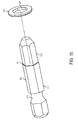
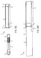
- a DeWALT DW2055 Magnetic Drive Guide 10 comprises a drive shaft 12, a socket shaft 20, and a sliding sleeve 30.
- the drive shaft 12 has a hex-shaped rear shank portion 14 configured to be received in a driving end of an electric screwdriving tool, an intermediate shaft portion 15 with longitudinal grooves 18, and a round front shaft portion 16.
- the front shaft portion 16 is non-rotatably press fit in a bore (not shown) in a rear end 22 of the socket shaft 20.
- a hex shaped socket (not shown) for receiving a screwdriving bit 36 is formed in a front end 24 of the socket shaft.
- a magnet (not shown) may be received in the socket to retain and magnetize the screwdriving bit.
- Coupled to the socket shaft 30 are a rear hog ring 26 at the rear 22 end and a front hog ring 28 at the front end 24.
- the sliding sleeve 30 is received over the socket shaft 20.
- the sliding sleeve 30 is hollow and cylindrical with a V-shaped internal annular groove 32 at its rear end 34. The sleeve can slide between a rear position ( Fig. 16A ) where the rear hog ring 26 is received in the annular groove 32, and a front position ( Fig. 16B ) where the front hog ring is received in the annular groove.
- the drive shaft 12 is composed of mild steel
- the socket shaft 20 is composed of aluminum
- the sliding sleeve 30 is composed of brass.
- a drive guide for driving fastening bits includes a drive shaft extending along an axis.
- the shaft has a rear shank portion configured to be coupled to a power tool and a front shaft portion extending axially forward of the rear shank portion.
- a socket shaft preferably composed of a non-paramagnetic material, extends along the axis.
- the socket shaft has a rear end with a coupling that non-rotationally attaches the rear end to the front shaft portion of the drive shaft and a front end having a socket open to the front end.
- the socket is configured to receive a fastening bit.
- a magnet is received in the socket with an air gap behind the magnet. The magnet is configured to magnetize a fastening bit received in the socket.
- a generally cylindrical sliding sleeve preferably composed of a non-paramagnetic material, is received over the socket shaft and is slidable along the axis between a rear position in which a front end of the sliding sleeve is aligned with or is axially rearward of the front end of the socket shaft and a forward position in which the front end of the sliding sleeve is axially forward of the front end of the socket shaft.
- the front socket may include a front hex portion for receiving a hex shaped fastening bit and a rear counterbore that receives the magnet.
- An internal shoulder may be integrally formed inside a rear end of the sliding sleeve, the internal shoulder having a second internal diameter that is less than a first internal diameter of the sliding sleeve.
- An external front shoulder may be integrally formed on the front end of the socket shaft, the front shoulder configured to abut against the internal shoulder when the sliding sleeve is in the forward position to prevent removal of the sliding sleeve from the socket shaft in the axial forward direction.
- the internal shoulder preferably is formed by swaging the rear end of the sliding sleeve.
- An external rear stop may be on one of the drive shaft and the socket shaft, the rear stop positioned to abut against the rear end of the sliding sleeve when the sliding sleeve is in the rear position.
- the rear stop may include a removable clip and/or an external rear shoulder integrally formed on one of the drive shaft and the socket shaft.
- An O-ring may be disposed on the socket shaft to frictionally resist axial movement of the sliding sleeve relative to the socket shaft.
- the drive shaft may be composed of a paramagnetic material.
- the drive shaft may be composed of a carbon steel material, and/or the socket shaft may be composed of a stainless steel material, and/or the sliding sleeve may be composed of one of a brass material, an aluminum material, and a stainless steel material.
- a drive guide for driving fastening bits includes a drive shaft extending along an axis.
- the drive shaft has a rear shank portion configured to be coupled to a power tool and a front shaft portion extending axially forward of the rear shank portion.
- a socket shaft extends along the axis and has a rear end with a coupling that non-rotationally attaches the rear end to the front shaft portion of the drive shaft and a front end having a socket open to the front end.
- the socket is configured to receive a fastening bit.
- a magnet is received in the socket and is configured to magnetize a fastening bit received in the socket.
- a generally cylindrical sliding sleeve is received over the socket shaft and is slidable along the axis between a rear position in which a front end of the sliding sleeve is aligned with or is axially rearward of the front end of the socket shaft and a forward position in which the front end of the sliding sleeve is axially forward of the front end of the socket shaft.
- the sliding sleeve has a first internal diameter.
- An internal rear stop is integrally formed inside a rear end of the sliding sleeve. The internal rear stop has a second internal diameter that is less than the first internal diameter.
- An external rear stop preferably is on one of the drive shaft and the socket shaft, the external rear stop positioned to abut against the internal rear stop of the sliding sleeve when the sliding sleeve is in the rear position.
- An external front shoulder preferably is integrally formed on the front end of the socket shaft. The external front shoulder preferably is configured to abut against the internal rear stop when the sliding sleeve is in the forward position to prevent removal of the sliding sleeve from the socket shaft in the axial forward direction.
- the internal shoulder may be formed by swaging the rear end of the sliding sleeve.
- the rear stop may include a removable clip and/or an external rear shoulder integrally formed on one of the drive shaft and the socket shaft.
- An O-ring may be disposed on the socket shaft to frictionally resist axial movement of the sliding sleeve relative to the socket shaft.
- the O-ring may be disposed on the front shoulder.
- the drive shaft may be formed of a paramagnetic material, and preferably the socket retainer and sleeve each may be formed of non-paramagnetic metal materials.
- the drive shaft may be composed of a carbon steel material
- the socket shaft may be composed of a stainless steel material
- the sliding sleeve advantageously may be composed of one of a brass material, an aluminum material, and a stainless steel material.
- a drive guide for driving fastening bits includes a drive shaft extending along an axis.
- the drive shaft has a rear shank portion configured to be coupled to a power tool and a front shaft portion extending axially forward of the rear shank portion.
- a socket shaft extends along the axis.
- the socket shaft has a rear end with a coupling that non-rotationally attaches the rear end to the front shaft portion of the drive shaft and a front end having a socket open to the front end.
- the socket is configured to receive a fastening bit.
- a magnet is received in the socket with an air gap behind the magnet and is configured to magnetize a fastening bit received in the socket.
- a generally cylindrical sliding sleeve is received over the socket shaft and is slidable along the axis between a rear position in which a front end of the sliding sleeve is aligned with or is axially rearward of the front end of the socket shaft and a forward position in which the front end of the sliding sleeve is axially forward of the front end of the socket shaft.
- the sliding sleeve has a first internal diameter.
- An internal shoulder is integrally formed inside a rear end of the sliding sleeve. The internal shoulder has a second internal diameter that is less than the first internal diameter.
- An external rear stop is on one of the drive shaft and the socket shaft, and is positioned to abut against the rear end of the sliding sleeve when the sliding sleeve is in the rear position.
- An external front shoulder preferably is integrally formed on the front end of the socket shaft, and preferably is configured to abut against the internal shoulder when the sliding sleeve is in the forward position to prevent removal of the sliding sleeve from the socket shaft in the axial forward direction.
- An O-ring preferably is disposed on the socket shaft to frictionally resist axial movement of the sliding sleeve relative to the socket shaft.
- the drive shaft preferably is composed of a paramagnetic material, and preferably the socket shaft and the sliding sleeve are each composed of a non-paramagnetic material.
- the drive shaft may be composed of a carbon steel material, and/or the socket shaft may be composed of a stainless steel material, and/or the sliding sleeve may be composed of one of a brass material, an aluminum material, and a stainless steel material.
- the drive guides have significantly improved life and durability when being used with an impact driver.
- the drive guides are better at magnetizing fastening bits in order to magnetically couple to a fastener.
- a drive guide 100 for driving fastening bits includes a drive shaft 110, a socket shaft 130, and a generally cylindrical sliding sleeve 150.
- the drive shaft 110 extends along an axis X and has a hex-shaped rear shank portion 112 with an annular groove 114 configured to be coupled to a power tool and a front shaft portion 116 extending axially forward of the rear shank portion 114 and configured to be non-rotatably coupled to the socket shaft 130.
- the front shaft portion 116 includes a round intermediate shaft 118 having a first diameter D1 and a front projection 120 of polygonal cross-section with a second diameter D2 (measured either across the flats or across the corners) that is smaller than the first diameter D1.
- the front projection 120 includes a tapered nose 122 at a front end 124.
- a rear external stop in the form of a rear external shoulder 126 is formed at a junction between the rear shank portion 114 and the front shaft portion 116.
- the rear external shoulder 126 has a third diameter D3 that is greater than both the first and second diameters D1 and D2.
- the socket shaft 130 extends along the axis X and has a rear end 132 with a coupling in the form of a bore 134 with a circular or polygonal cross-section.
- the front projection 120 is press-fit into the bore 134 to non-rotationally couple the drive shaft 110 to the socket shaft 130.
- the socket shaft 130 also has front end 138 with a hex shaped socket 136 that is configured to receive a fastening bit (e.g., a screwdriving bit, not shown).
- a fastening bit e.g., a screwdriving bit, not shown.
- At the base of the socket 136 is a round counterbore 140 that receives a magnet 142 in a press-fit manner.
- the magnet 142 fits into the counterbore 140 so that a portion of the magnet extends into the socket 136 and so that there is an air gap 144 behind the magnet 142 between the magnet 142 and the front end 124 of the drive shaft 110. This enables the magnet 142 to magnetize a fastening bit received in the socket 136, which in turn magnetically couples to a fastener to be driven, without significantly magnetizing the drive shaft 110.
- a front external stop in the form of an external front shoulder 146 is formed at the front end 138 of the socket shaft 130.
- the front shoulder 146 has a fourth diameter D4 that is greater than the second diameter D2 and less than or equal to the third diameter D3.
- the generally cylindrical sliding sleeve 150 extends along the axis X and has a front end 156 and a rear end 158.
- the sliding sleeve 150 includes a rear internal stop in the form of a rear internal shoulder 152 formed on an internal wall 154 of the sliding sleeve 150.
- the sleeve 150 is received over the drive shaft 110 and the socket shaft 130 so that it is slidable along the axis X between a rear position ( Fig. 1B ) in which the internal shoulder 152 abuts the rear external shoulder 126 and a forward position ( Fig. 1A ) in which the internal shoulder 152 abuts the front external shoulder 146.
- the front end 156 of the sliding sleeve 150 is aligned with or is axially rearward of the front end 138 of the socket shaft 130.
- the front end 156 of the sliding sleeve 150 is axially forward of the front end 138 of the socket shaft 130.
- the sliding sleeve has a fifth internal diameter D5 that is slightly greater than the fourth diameter D4 of the front external shoulder 146 of the socket shaft 130, except for the rear internal shoulder 152, which has a sixth diameter D6 that is slightly greater than the first diameter D1 of the intermediate portion 118 of the drive shaft 110.
- the rear end 158 of the sliding sleeve 150 is slid over the front shaft portion 116 of the drive shaft 110 until the internal shoulder 152 of the sliding sleeve 150 abuts the rear external shoulder 126 of the drive shaft 110.
- the socket shaft 130 is inserted through the front end 156 of the sliding sleeve 150 and the front projection 120 of the drive shaft 110 is press fit into the rear bore 134 in the socket shaft 130.
- the magnet 142 is press fit into the counterbore 140 in the socket 136, leaving an air gap 144 between the magnet 142 and the drive shaft 110.
- the sliding sleeve 150 may now slide between its rearward position ( Fig.
- a drive guide 200 for driving fastening bits includes a drive shaft 210, a socket shaft 230, and a generally cylindrical sliding sleeve 250.
- the drive shaft 210 extends along an axis X and has a hex-shaped rear shank portion 212 with an annular groove 214 configured to be coupled to a power tool and a front polygonal (e.g., hex shaped) shaft portion 216 extending axially forward of the rear shank portion 214 and configured to be non-rotatably coupled to the socket shaft 230.
- the front shaft portion 216 has a first diameter D1 (measured either across the flats or across the corners) and a tapered nose 222 at a front end 224.
- the socket shaft 230 is generally cylindrical with a second diameter D2 (which is greater than the first diameter D1) and extends along the axis X.
- the socket shaft 230 has a rear end 232 with a coupling in the form of a bore 234 with a non-circular (e.g., hex shaped) cross-section.
- the front portion 216 of the drive shaft 210 is press-fit into the bore 234 to non-rotationally couple the drive shaft 210 to the socket shaft 230.
- the socket shaft 230 also has an intermediate shaft portion 235 and a front end 238 with a hex shaped socket 236 that is configured to receive a fastening bit (e.g., a screwdriving bit, not shown).
- a round counterbore 240 that receives a magnet 242 in a press-fit manner.
- the magnet 242 fits into the counterbore 240 so that a portion of the magnet extends into the socket 236 and so that there is an air gap 244 behind the magnet 242.
- a front external stop in the form of an external front shoulder 246 is formed at the front end 238 of the socket shaft 230.
- the front shoulder 246 has a third diameter D3 that is greater than the second diameter D2.
- the front shoulder 246 also has an annular groove 251 that receives an elastomeric O-ring 249 to frictionally resist (but not stop) movement of the sliding sleeve 250 relative to the socket shaft 230.
- Received in the rear end 232 of the socket shaft 230 is rear external stop in the form of a C-clip or hog ring 245 that has an outer diameter when installed that is approximately greater than or equal to the third diameter D3.
- the generally cylindrical sliding sleeve 250 extends along the axis X and has a front end 256 and a rear end 258.
- the sliding sleeve 250 includes a rear internal stop in the form of a rear internal shoulder 252 that is formed by swaging or crimping the rear end 258 of the sliding sleeve 250.
- the sleeve 250 is received over the drive shaft 210 and the socket shaft 230 so that it is slidable along the axis X between a rear position ( Fig. 5B ) in which the internal shoulder 252 abuts the rear C-clip or hog ring 245 and a forward position ( Fig. 5A ) in which the internal shoulder 252 abuts the front external shoulder 246.
- the front end 256 of the sliding sleeve 250 is aligned with or is axially rearward of the front end 238 of the socket shaft 230.
- the front end 256 of the sliding sleeve 250 is axially forward of the front end 238 of the socket shaft 230.
- the sliding sleeve has a fourth internal diameter D4 that is slightly greater than the third diameter D3 of the front external shoulder 246 of the socket shaft 230, except for the rear internal shoulder 252, which has a fifth diameter D5 that is less than the third diameter D3 and slightly greater than the second diameter D2 of the socket shaft 230.
- the front portion 216 of the socket shaft 230 is press fit into the rear bore 234 in the socket shaft 230.
- the magnet 242 is press fit into the counterbore 240 in the socket 236, leaving an air gap 244 behind the magnet 242.
- the O-ring 249 is next coupled to the annular groove in the front shoulder 246 of the socket shaft 230.
- the front end 258 of the sliding sleeve 250 is then slid over the rear shank portion 212 of the drive shaft 210 until the internal shoulder 252 of the sliding sleeve 250 abuts the front external shoulder 246 of the socket sleeve 230.
- the C-clip or hog ring 245 is coupled to an annular groove 237 in the rear end 232 of the socket sleeve 230 to act as a rear external stop.
- the sliding sleeve 250 may now slide between its rearward position ( Fig. 5B ) where the internal shoulder 252 of the sliding sleeve 250 abuts the rear C-clip or hog ring 245 on the socket shaft 230 and its forward position ( Fig. 5A ) where the internal shoulder 252 of the sliding sleeve 250 abuts the front external shoulder 246 of the socket shaft 230.
- a drive guide 300 for driving fastening bits includes a drive shaft 310, a socket shaft 330, and a generally cylindrical sliding sleeve 350.
- the drive shaft 310 extends along an axis X and has a hex-shaped rear shank portion 312 with an annular groove 314 configured to be coupled to a power tool and a front shaft portion 316 extending axially forward of the rear shank portion 314 and configured to be non-rotatably coupled to the socket shaft 330.
- the front shaft portion 316 includes a round intermediate shaft 318 having a first diameter D1 and a front projection 320 of polygonal (e.g., hex shaped) cross section with a second diameter D2 (measured either across the flats or across the corners) that is smaller than the first diameter D1.
- the front projection 320 includes a tapered nose 322 at a front end 324.
- a rear external stop in the form of a rear external shoulder 326 is formed at a junction between the rear shank portion 314 and the front shaft portion 316.
- the rear external shoulder 326 has a third diameter D3 that is greater than both the first and second diameters D1 and D2.
- the socket shaft 330 extends along the axis X and has a rear end 332 with a coupling in the form of a bore 334 with a non-circular (e.g., hex shaped) cross-section.
- the front projection 320 is press-fit into the bore 334 to non-rotationally couple the drive shaft 310 to the socket shaft 330.
- the socket shaft 330 also has front end 338 with a hex shaped socket 336 that is configured to receive a fastening bit (e.g., a screwdriving bit, not shown).
- a fastening bit e.g., a screwdriving bit, not shown.
- At the base of the socket 336 is a round counterbore 340 that receives a magnet 342 in a press-fit manner.
- the magnet 342 fits into the counterbore 340 so that a portion of the magnet extends into the socket 336 and so that there is an air gap 344 behind the magnet 342 and between the magnet 342 and the front end 324 of the drive shaft 310. This enables the magnet 342 to magnetize a fastening bit received in the socket 336 so that the fastening bit can magnetically couple to a fastener to be driven without significantly magnetizing the drive shaft 310.
- a front external stop in the form of an external front shoulder 346 is formed at the front end 338 of the socket shaft 330.
- the front shoulder 346 has a fourth diameter D4 that is greater than the second diameter D2 and less than or equal to the third diameter D3.
- the generally cylindrical sliding sleeve 350 extends along the axis X and has a front end 356 and a rear end 358.
- the sliding sleeve 350 includes a rear internal stop in the form of a rear internal shoulder 352 that is formed by swaging or crimping the rear end 358 of the sliding sleeve 350.
- the sleeve 350 is received over the drive shaft 310 and the socket shaft 330 so that it is slidable along the axis X between a rear position ( Fig. 9B ) in which the internal shoulder 352 abuts the rear external shoulder 326 on the drive shaft 310 and a forward position ( Fig.
- the internal shoulder 352 abuts the front external shoulder 346 on the socket shaft 330.
- the front end 356 of the sliding sleeve 350 is aligned with or is axially rearward of the front end 338 of the socket shaft 330.
- the front end 356 of the sliding sleeve 350 is axially forward of the front end 338 of the socket shaft 330.
- the sliding sleeve has a fifth internal diameter D5 that is slightly greater than the fourth diameter D4 of the front external shoulder 346 of the socket shaft 330, except for the rear internal shoulder 352, which has a sixth internal diameter D6 that is less than the fifth diameter D5 and slightly greater than the first diameter D1 of the drive shaft 310.
- the rear end 358 of the sliding sleeve 350 is slid over the front shaft portion 316 of the drive shaft 310 until the internal shoulder 352 of the sliding sleeve 350 abuts the rear external shoulder 326 of the drive shaft 310.
- the socket shaft 330 is inserted through the front end 356 of the sliding sleeve 350 and the front projection 320 of the drive shaft 310 is press fit into the rear bore 334 in the socket shaft 330.
- the magnet 342 is press fit into the counterbore 340 in the socket 336, leaving an air gap 344 behind the magnet 342 and between the magnet 342 and the drive shaft 310.
- the sliding sleeve 350 may now slide between its rearward position ( Fig.
- a drive guide 400 for driving fastening bits includes a drive shaft 410, a socket shaft 430, and a generally cylindrical sliding sleeve 450 that are similar to the drive shaft 310, the socket shaft 330, and the sliding sleeve 350 of the third embodiment.
- the drive guide 400 of the fourth embodiment differs from the drive guide 300 of the third embodiment in the way that a rear stop in the form of a rear internal shoulder 452 is formed in a rear end 458 of the sliding sleeve 450.
- the sliding sleeve 450 has a first internal diameter D1 that is slightly greater than a second external diameter D2 of a front external shoulder 446 on the socket shaft 430.
- the rear end 458 of the sliding sleeve 450 is formed with a plurality of axial slots 454.
- a retaining ring 456 is received over the slotted rear end 458 of the sliding sleeve 450.
- the retaining ring 456 has an third internal diameter D3 that may be less than the first internal diameter D1 of the sliding sleeve 450.
- the retaining ring 456 compresses the slotted rear end 458 of the sliding sleeve 450 to a fourth internal diameter D4 that is smaller than the first internal diameter D1 to form the internal shoulder.
- the outer diameter of the retaining ring 456 may be the same as the outer diameter of the sliding sleeve.
- a drive shaft 500 may be substituted for one of the drive shafts 110, 210, 310, and 410 of the first, second, third, and fourth embodiments.
- the drive shaft 500 includes a hex-shaped rear shank portion 512 with an annular groove 514 configured to be coupled to a power tool and a front shaft circular or polygonal (e.g., hex-shaped) portion 516 extending axially forward of the rear shank portion 514 and configured to be non-rotatably coupled to one of the socket shafts 130, 230, 330, and 430.
- the front shaft portion 516 has a smaller diameter than a diameter of the rear shank portion 512 (measured either across the flats or across the corners) to form an internal shoulder 517 at the junction between the rear shank portion 512 and the front shaft portion 516.
- a ring 519 with a circular or polygonal (e.g., hex-shaped) opening 521 is received over the front shaft portion 516 and abuts the internal shoulder 517.
- the ring 519 has a larger outer diameter than both the rear shank portion 512 and the front shaft portion 516.
- the ring 519 acts as the rear outer shoulder in the first, second, third, and fourth embodiments described above.
- the drive shaft may be composed of a relatively strong and durable paramagnetic material such as a mild carbon steel alloy, e.g., 6150 steel.
- the socket shaft may be composed of a strong and durable non-paramagnetic material, such as a stainless steel alloy, e.g., type 302 stainless steel.
- the sliding sleeve may be composed of a relatively strong and durable non-paramagnetic material such as a stainless steel alloy (e.g., type 302 stainless steel), an aluminum alloy (e.g., 2A12-T4), or a brass alloy (e.g., H65-Y2).
- the shank of the drive shaft is coupled to a bit holder or chuck of a rotary power tool.
- the sliding sleeve is retracted to its rearward position and a fastening bit is inserted into the socket.
- the working end of the fastening bit is magnetized by the magnet and is used to engage the head of a fastener (such as a screw). While the fastener is engaged by the fastening bit, the sliding sleeve is slid forward over the fastening bit and the fastener to its forward position.
- the power tool is activated to drive the drive shaft, which in turn drives the socket shaft, the fastening bit, and the fastener to drive the fastener into a workpiece.
- the sliding sleeve retracts toward its rearward position until the fastener is seated in the workpiece.
- the sliding sleeve helps keep the fastener aligned axially with the axis X of the drive guide.
- the impact driver, drive guide, and screwdriving bit was used to drive #10 x 3" deck screws through two pieces of 2" pressure treated yellow pine to screw them together.
- the test proceeded until the drive guide was used to drive 2500 screws or until the drive guide failed by ceasing to function as intended. After completion of the test, each drive guide was inspected for damage. The results of the test are summarized in the following table.
Landscapes
- Engineering & Computer Science (AREA)
- Mechanical Engineering (AREA)
- Details Of Spanners, Wrenches, And Screw Drivers And Accessories (AREA)
Abstract
Description
- This application relates to a drive guide for a fastening bit.
- Drive guides are known to retain and drive fastening bits (such as screwdriving bits) using a power tool. As shown in
Figs. 16A-16D , in one prior art example, a DeWALT DW2055Magnetic Drive Guide 10 comprises adrive shaft 12, asocket shaft 20, and asliding sleeve 30. Thedrive shaft 12 has a hex-shapedrear shank portion 14 configured to be received in a driving end of an electric screwdriving tool, anintermediate shaft portion 15 withlongitudinal grooves 18, and a roundfront shaft portion 16. Thefront shaft portion 16 is non-rotatably press fit in a bore (not shown) in arear end 22 of thesocket shaft 20. A hex shaped socket (not shown) for receiving ascrewdriving bit 36 is formed in afront end 24 of the socket shaft. A magnet (not shown) may be received in the socket to retain and magnetize the screwdriving bit. Coupled to thesocket shaft 30 are arear hog ring 26 at the rear 22 end and afront hog ring 28 at thefront end 24. Thesliding sleeve 30 is received over thesocket shaft 20. Thesliding sleeve 30 is hollow and cylindrical with a V-shaped internalannular groove 32 at itsrear end 34. The sleeve can slide between a rear position (Fig. 16A ) where therear hog ring 26 is received in theannular groove 32, and a front position (Fig. 16B ) where the front hog ring is received in the annular groove. Thedrive shaft 12 is composed of mild steel, thesocket shaft 20 is composed of aluminum, and thesliding sleeve 30 is composed of brass. - These prior art drive guides tend to fail frequently (e.g., approximately 50% of the time or more), especially when used with an impact driver. The usual points of failure are the rear hog ring becoming jammed in the V-shaped annular groove in the sliding sleeve and the socket in the front of the socket shaft fracturing or becoming worn. After use in an impact driver, the sliding sleeve can be difficult to slide between the rearward and forward positions and tends to get stuck in one of these positions. Finally, regardless of whether the drive guide is used in an impact driver, some of the magnetism from the magnet tends to magnetize the drive shaft, which reduces the magnetic field available to magnetize the fastening bit and in turn magnetically retain a fastener. It is desirable to have a drive guide with better performance with an impact driver.
- In an aspect of the present invention, a drive guide for driving fastening bits includes a drive shaft extending along an axis. The shaft has a rear shank portion configured to be coupled to a power tool and a front shaft portion extending axially forward of the rear shank portion. A socket shaft, preferably composed of a non-paramagnetic material, extends along the axis. The socket shaft has a rear end with a coupling that non-rotationally attaches the rear end to the front shaft portion of the drive shaft and a front end having a socket open to the front end. The socket is configured to receive a fastening bit. A magnet is received in the socket with an air gap behind the magnet. The magnet is configured to magnetize a fastening bit received in the socket. A generally cylindrical sliding sleeve, preferably composed of a non-paramagnetic material, is received over the socket shaft and is slidable along the axis between a rear position in which a front end of the sliding sleeve is aligned with or is axially rearward of the front end of the socket shaft and a forward position in which the front end of the sliding sleeve is axially forward of the front end of the socket shaft.
- Implementations of this, and the following other aspects of the invention may include one or more of the following features. The front socket may include a front hex portion for receiving a hex shaped fastening bit and a rear counterbore that receives the magnet. An internal shoulder may be integrally formed inside a rear end of the sliding sleeve, the internal shoulder having a second internal diameter that is less than a first internal diameter of the sliding sleeve. An external front shoulder may be integrally formed on the front end of the socket shaft, the front shoulder configured to abut against the internal shoulder when the sliding sleeve is in the forward position to prevent removal of the sliding sleeve from the socket shaft in the axial forward direction. The internal shoulder preferably is formed by swaging the rear end of the sliding sleeve. An external rear stop may be on one of the drive shaft and the socket shaft, the rear stop positioned to abut against the rear end of the sliding sleeve when the sliding sleeve is in the rear position. The rear stop may include a removable clip and/or an external rear shoulder integrally formed on one of the drive shaft and the socket shaft. An O-ring may be disposed on the socket shaft to frictionally resist axial movement of the sliding sleeve relative to the socket shaft. The drive shaft may be composed of a paramagnetic material. The drive shaft may be composed of a carbon steel material, and/or the socket shaft may be composed of a stainless steel material, and/or the sliding sleeve may be composed of one of a brass material, an aluminum material, and a stainless steel material.
- In another aspect of the invention, a drive guide for driving fastening bits includes a drive shaft extending along an axis. The drive shaft has a rear shank portion configured to be coupled to a power tool and a front shaft portion extending axially forward of the rear shank portion. A socket shaft extends along the axis and has a rear end with a coupling that non-rotationally attaches the rear end to the front shaft portion of the drive shaft and a front end having a socket open to the front end. The socket is configured to receive a fastening bit. A magnet is received in the socket and is configured to magnetize a fastening bit received in the socket. A generally cylindrical sliding sleeve is received over the socket shaft and is slidable along the axis between a rear position in which a front end of the sliding sleeve is aligned with or is axially rearward of the front end of the socket shaft and a forward position in which the front end of the sliding sleeve is axially forward of the front end of the socket shaft. The sliding sleeve has a first internal diameter. An internal rear stop is integrally formed inside a rear end of the sliding sleeve. The internal rear stop has a second internal diameter that is less than the first internal diameter. An external rear stop preferably is on one of the drive shaft and the socket shaft, the external rear stop positioned to abut against the internal rear stop of the sliding sleeve when the sliding sleeve is in the rear position. An external front shoulder preferably is integrally formed on the front end of the socket shaft. The external front shoulder preferably is configured to abut against the internal rear stop when the sliding sleeve is in the forward position to prevent removal of the sliding sleeve from the socket shaft in the axial forward direction.
- Implementations of this, and the other aspects of the invention may include one or more of the following features. The internal shoulder may be formed by swaging the rear end of the sliding sleeve. The rear stop may include a removable clip and/or an external rear shoulder integrally formed on one of the drive shaft and the socket shaft. An O-ring may be disposed on the socket shaft to frictionally resist axial movement of the sliding sleeve relative to the socket shaft. The O-ring may be disposed on the front shoulder. The drive shaft may be formed of a paramagnetic material, and preferably the socket retainer and sleeve each may be formed of non-paramagnetic metal materials. The drive shaft may be composed of a carbon steel material, the socket shaft may be composed of a stainless steel material, and the sliding sleeve advantageously may be composed of one of a brass material, an aluminum material, and a stainless steel material.
- In another aspect of the invention, a drive guide for driving fastening bits includes a drive shaft extending along an axis. The drive shaft has a rear shank portion configured to be coupled to a power tool and a front shaft portion extending axially forward of the rear shank portion. A socket shaft extends along the axis. The socket shaft has a rear end with a coupling that non-rotationally attaches the rear end to the front shaft portion of the drive shaft and a front end having a socket open to the front end. The socket is configured to receive a fastening bit. A magnet is received in the socket with an air gap behind the magnet and is configured to magnetize a fastening bit received in the socket. A generally cylindrical sliding sleeve is received over the socket shaft and is slidable along the axis between a rear position in which a front end of the sliding sleeve is aligned with or is axially rearward of the front end of the socket shaft and a forward position in which the front end of the sliding sleeve is axially forward of the front end of the socket shaft. The sliding sleeve has a first internal diameter. An internal shoulder is integrally formed inside a rear end of the sliding sleeve. The internal shoulder has a second internal diameter that is less than the first internal diameter. An external rear stop is on one of the drive shaft and the socket shaft, and is positioned to abut against the rear end of the sliding sleeve when the sliding sleeve is in the rear position. An external front shoulder preferably is integrally formed on the front end of the socket shaft, and preferably is configured to abut against the internal shoulder when the sliding sleeve is in the forward position to prevent removal of the sliding sleeve from the socket shaft in the axial forward direction. An O-ring preferably is disposed on the socket shaft to frictionally resist axial movement of the sliding sleeve relative to the socket shaft. The drive shaft preferably is composed of a paramagnetic material, and preferably the socket shaft and the sliding sleeve are each composed of a non-paramagnetic material. In one implementation of this aspect of the invention, the drive shaft may be composed of a carbon steel material, and/or the socket shaft may be composed of a stainless steel material, and/or the sliding sleeve may be composed of one of a brass material, an aluminum material, and a stainless steel material.
- Advantages may include one or more of the following. The drive guides have significantly improved life and durability when being used with an impact driver. In addition, the drive guides are better at magnetizing fastening bits in order to magnetically couple to a fastener. These and other advantages and features of example embodiments of the invention will be apparent from the following description and the drawings.
-
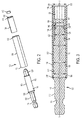
FIG. 1A is a perspective view of a first embodiment of a drive guide with the sliding sleeve in a forward position. -
FIG. 1B is a perspective view of the drive guide ofFIG. 1A with the sliding sleeve in a rearward position. -
FIG. 2 is an exploded perspective view of the drive guide ofFIG. 1A . -
FIG. 3 is an assembled cross-sectional view of the drive guide ofFIG. 1A . -
FIG. 4 is an exploded cross-sectional view of the drive guide ofFIG. 1A . -
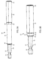
FIG. 5A is a perspective view of a second embodiment of a drive guide with the sliding sleeve in a forward position. -
FIG. 5B is a perspective view of the drive guide ofFIG. 5A with the sliding sleeve in a rearward position. -
FIG. 6 is an exploded perspective view of the drive guide ofFIG. 5A . -
FIG. 7 is an assembled cross-sectional view of the drive guide ofFIG. 5A . -
FIG. 8 is an exploded cross-sectional view of the drive guide ofFIG. 5A . -
FIG. 9A is a perspective view of a third embodiment of a drive guide with the sliding sleeve in a forward position. -
FIG. 9B is a perspective view of the drive guide ofFIG. 9A with the sliding sleeve in a rearward position. -
FIG. 10 is an exploded perspective view of the drive guide ofFIG. 9A . -
FIG. 11 is an assembled cross-sectional view of the drive guide ofFIG. 9A . -
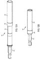
FIG. 12A is a perspective view of a fourth embodiment of a drive guide with the sliding sleeve in a forward position. -
FIG. 12B is a perspective view of the drive guide ofFIG. 12A with the sliding sleeve in a rearward position. -
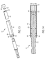
FIG. 13 is an exploded perspective view of the drive guide ofFIG. 12A . -
FIG. 14 is an assembled cross-sectional view of the drive guide ofFIG. 12A . -
FIG. 15 is a perspective view of another embodiment of a drive shaft for use with the drive guides ofFIGS. 1A ,5A ,9A , and12A . -
FIG. 16A is a perspective view of a prior art design of a drive guide with the sliding sleeve in a forward position. -
FIG. 16B is a perspective view of the drive guide ofFIG. 16A with the sliding sleeve in a rearward position. -
FIG. 16C is a partially exploded perspective view of the drive guide ofFIG. 16A . -
FIG. 16D close-up perspective view of a portion of the drive guide ofFIG. 16A . - Referring to
FIGS. 1A-4 , in a first embodiment of the invention, adrive guide 100 for driving fastening bits includes adrive shaft 110, asocket shaft 130, and a generally cylindrical slidingsleeve 150. Thedrive shaft 110 extends along an axis X and has a hex-shapedrear shank portion 112 with anannular groove 114 configured to be coupled to a power tool and afront shaft portion 116 extending axially forward of therear shank portion 114 and configured to be non-rotatably coupled to thesocket shaft 130. Thefront shaft portion 116 includes a roundintermediate shaft 118 having a first diameter D1 and afront projection 120 of polygonal cross-section with a second diameter D2 (measured either across the flats or across the corners) that is smaller than the first diameter D1. Thefront projection 120 includes atapered nose 122 at afront end 124. A rear external stop in the form of a rearexternal shoulder 126 is formed at a junction between therear shank portion 114 and thefront shaft portion 116. The rearexternal shoulder 126 has a third diameter D3 that is greater than both the first and second diameters D1 and D2. - The
socket shaft 130 extends along the axis X and has arear end 132 with a coupling in the form of abore 134 with a circular or polygonal cross-section. Thefront projection 120 is press-fit into thebore 134 to non-rotationally couple thedrive shaft 110 to thesocket shaft 130. Thesocket shaft 130 also hasfront end 138 with a hex shapedsocket 136 that is configured to receive a fastening bit (e.g., a screwdriving bit, not shown). At the base of thesocket 136 is around counterbore 140 that receives amagnet 142 in a press-fit manner. Themagnet 142 fits into thecounterbore 140 so that a portion of the magnet extends into thesocket 136 and so that there is anair gap 144 behind themagnet 142 between themagnet 142 and thefront end 124 of thedrive shaft 110. This enables themagnet 142 to magnetize a fastening bit received in thesocket 136, which in turn magnetically couples to a fastener to be driven, without significantly magnetizing thedrive shaft 110. A front external stop in the form of an externalfront shoulder 146 is formed at thefront end 138 of thesocket shaft 130. Thefront shoulder 146 has a fourth diameter D4 that is greater than the second diameter D2 and less than or equal to the third diameter D3. - The generally cylindrical sliding
sleeve 150 extends along the axis X and has afront end 156 and arear end 158. The slidingsleeve 150 includes a rear internal stop in the form of a rearinternal shoulder 152 formed on aninternal wall 154 of the slidingsleeve 150. Thesleeve 150 is received over thedrive shaft 110 and thesocket shaft 130 so that it is slidable along the axis X between a rear position (Fig. 1B ) in which theinternal shoulder 152 abuts the rearexternal shoulder 126 and a forward position (Fig. 1A ) in which theinternal shoulder 152 abuts the frontexternal shoulder 146. In the rear position, thefront end 156 of the slidingsleeve 150 is aligned with or is axially rearward of thefront end 138 of thesocket shaft 130. In the forward position, thefront end 156 of the slidingsleeve 150 is axially forward of thefront end 138 of thesocket shaft 130. The sliding sleeve has a fifth internal diameter D5 that is slightly greater than the fourth diameter D4 of the frontexternal shoulder 146 of thesocket shaft 130, except for the rearinternal shoulder 152, which has a sixth diameter D6 that is slightly greater than the first diameter D1 of theintermediate portion 118 of thedrive shaft 110. - As shown in
FIG. 4 , to assemble thedrive guide 100, therear end 158 of the slidingsleeve 150 is slid over thefront shaft portion 116 of thedrive shaft 110 until theinternal shoulder 152 of the slidingsleeve 150 abuts the rearexternal shoulder 126 of thedrive shaft 110. Next, thesocket shaft 130 is inserted through thefront end 156 of the slidingsleeve 150 and thefront projection 120 of thedrive shaft 110 is press fit into therear bore 134 in thesocket shaft 130. Finally, themagnet 142 is press fit into thecounterbore 140 in thesocket 136, leaving anair gap 144 between themagnet 142 and thedrive shaft 110. The slidingsleeve 150 may now slide between its rearward position (Fig. 1B ) where theinternal shoulder 152 of the slidingsleeve 150 abuts the rearexternal shoulder 126 of thedrive shaft 110 and its forward position (Fig. 1A ) where theinternal shoulder 152 of the slidingsleeve 150 abuts the frontexternal shoulder 146 of thesocket shaft 130.
Referring toFIGS. 5A-8 , in a second embodiment of the invention, adrive guide 200 for driving fastening bits includes adrive shaft 210, asocket shaft 230, and a generally cylindrical slidingsleeve 250. Thedrive shaft 210 extends along an axis X and has a hex-shapedrear shank portion 212 with anannular groove 214 configured to be coupled to a power tool and a front polygonal (e.g., hex shaped)shaft portion 216 extending axially forward of therear shank portion 214 and configured to be non-rotatably coupled to thesocket shaft 230. Thefront shaft portion 216 has a first diameter D1 (measured either across the flats or across the corners) and atapered nose 222 at afront end 224. - The
socket shaft 230 is generally cylindrical with a second diameter D2 (which is greater than the first diameter D1) and extends along the axis X. Thesocket shaft 230 has arear end 232 with a coupling in the form of abore 234 with a non-circular (e.g., hex shaped) cross-section. Thefront portion 216 of thedrive shaft 210 is press-fit into thebore 234 to non-rotationally couple thedrive shaft 210 to thesocket shaft 230. Thesocket shaft 230 also has anintermediate shaft portion 235 and afront end 238 with a hex shapedsocket 236 that is configured to receive a fastening bit (e.g., a screwdriving bit, not shown). At the base of thesocket 236 is around counterbore 240 that receives amagnet 242 in a press-fit manner. Themagnet 242 fits into thecounterbore 240 so that a portion of the magnet extends into thesocket 236 and so that there is anair gap 244 behind themagnet 242. This enables themagnet 242 to magnetize a fastening bit received in thesocket 236 so that the fastening bit can magnetically couple to a fastener to be driven, without significantly magnetizing thedrive shaft 210. A front external stop in the form of an externalfront shoulder 246 is formed at thefront end 238 of thesocket shaft 230. Thefront shoulder 246 has a third diameter D3 that is greater than the second diameter D2. Thefront shoulder 246 also has anannular groove 251 that receives an elastomeric O-ring 249 to frictionally resist (but not stop) movement of the slidingsleeve 250 relative to thesocket shaft 230. Received in therear end 232 of thesocket shaft 230 is rear external stop in the form of a C-clip orhog ring 245 that has an outer diameter when installed that is approximately greater than or equal to the third diameter D3. - The generally cylindrical sliding
sleeve 250 extends along the axis X and has afront end 256 and arear end 258. The slidingsleeve 250 includes a rear internal stop in the form of a rearinternal shoulder 252 that is formed by swaging or crimping therear end 258 of the slidingsleeve 250. Thesleeve 250 is received over thedrive shaft 210 and thesocket shaft 230 so that it is slidable along the axis X between a rear position (Fig. 5B ) in which theinternal shoulder 252 abuts the rear C-clip orhog ring 245 and a forward position (Fig. 5A ) in which theinternal shoulder 252 abuts the frontexternal shoulder 246. In the rear position, thefront end 256 of the slidingsleeve 250 is aligned with or is axially rearward of thefront end 238 of thesocket shaft 230. In the forward position, thefront end 256 of the slidingsleeve 250 is axially forward of thefront end 238 of thesocket shaft 230. The sliding sleeve has a fourth internal diameter D4 that is slightly greater than the third diameter D3 of the frontexternal shoulder 246 of thesocket shaft 230, except for the rearinternal shoulder 252, which has a fifth diameter D5 that is less than the third diameter D3 and slightly greater than the second diameter D2 of thesocket shaft 230. - As shown in
FIG. 8 , to assemble thedrive guide 200, thefront portion 216 of thesocket shaft 230 is press fit into therear bore 234 in thesocket shaft 230. Next, themagnet 242 is press fit into thecounterbore 240 in thesocket 236, leaving anair gap 244 behind themagnet 242. The O-ring 249 is next coupled to the annular groove in thefront shoulder 246 of thesocket shaft 230. Thefront end 258 of the slidingsleeve 250 is then slid over therear shank portion 212 of thedrive shaft 210 until theinternal shoulder 252 of the slidingsleeve 250 abuts the frontexternal shoulder 246 of thesocket sleeve 230. Next, the C-clip orhog ring 245 is coupled to anannular groove 237 in therear end 232 of thesocket sleeve 230 to act as a rear external stop. The slidingsleeve 250 may now slide between its rearward position (Fig. 5B ) where theinternal shoulder 252 of the slidingsleeve 250 abuts the rear C-clip orhog ring 245 on thesocket shaft 230 and its forward position (Fig. 5A ) where theinternal shoulder 252 of the slidingsleeve 250 abuts the frontexternal shoulder 246 of thesocket shaft 230. - Referring to
FIGS. 9A-11 , in a third embodiment of the invention, adrive guide 300 for driving fastening bits includes adrive shaft 310, asocket shaft 330, and a generally cylindrical slidingsleeve 350. Thedrive shaft 310 extends along an axis X and has a hex-shapedrear shank portion 312 with anannular groove 314 configured to be coupled to a power tool and afront shaft portion 316 extending axially forward of therear shank portion 314 and configured to be non-rotatably coupled to thesocket shaft 330. Thefront shaft portion 316 includes a roundintermediate shaft 318 having a first diameter D1 and afront projection 320 of polygonal (e.g., hex shaped) cross section with a second diameter D2 (measured either across the flats or across the corners) that is smaller than the first diameter D1. Thefront projection 320 includes atapered nose 322 at afront end 324. A rear external stop in the form of a rearexternal shoulder 326 is formed at a junction between therear shank portion 314 and thefront shaft portion 316. The rearexternal shoulder 326 has a third diameter D3 that is greater than both the first and second diameters D1 and D2. - The
socket shaft 330 extends along the axis X and has arear end 332 with a coupling in the form of abore 334 with a non-circular (e.g., hex shaped) cross-section. Thefront projection 320 is press-fit into thebore 334 to non-rotationally couple thedrive shaft 310 to thesocket shaft 330. Thesocket shaft 330 also hasfront end 338 with a hex shapedsocket 336 that is configured to receive a fastening bit (e.g., a screwdriving bit, not shown). At the base of thesocket 336 is around counterbore 340 that receives amagnet 342 in a press-fit manner. Themagnet 342 fits into thecounterbore 340 so that a portion of the magnet extends into thesocket 336 and so that there is anair gap 344 behind themagnet 342 and between themagnet 342 and thefront end 324 of thedrive shaft 310. This enables themagnet 342 to magnetize a fastening bit received in thesocket 336 so that the fastening bit can magnetically couple to a fastener to be driven without significantly magnetizing thedrive shaft 310. A front external stop in the form of an externalfront shoulder 346 is formed at thefront end 338 of thesocket shaft 330. Thefront shoulder 346 has a fourth diameter D4 that is greater than the second diameter D2 and less than or equal to the third diameter D3. - The generally cylindrical sliding
sleeve 350 extends along the axis X and has afront end 356 and arear end 358. The slidingsleeve 350 includes a rear internal stop in the form of a rearinternal shoulder 352 that is formed by swaging or crimping therear end 358 of the slidingsleeve 350. Thesleeve 350 is received over thedrive shaft 310 and thesocket shaft 330 so that it is slidable along the axis X between a rear position (Fig. 9B ) in which theinternal shoulder 352 abuts the rearexternal shoulder 326 on thedrive shaft 310 and a forward position (Fig. 5A ) in which theinternal shoulder 352 abuts the frontexternal shoulder 346 on thesocket shaft 330. In the rear position, thefront end 356 of the slidingsleeve 350 is aligned with or is axially rearward of thefront end 338 of thesocket shaft 330. In the forward position, thefront end 356 of the slidingsleeve 350 is axially forward of thefront end 338 of thesocket shaft 330. The sliding sleeve has a fifth internal diameter D5 that is slightly greater than the fourth diameter D4 of the frontexternal shoulder 346 of thesocket shaft 330, except for the rearinternal shoulder 352, which has a sixth internal diameter D6 that is less than the fifth diameter D5 and slightly greater than the first diameter D1 of thedrive shaft 310. - To assemble the
drive guide 300, therear end 358 of the slidingsleeve 350 is slid over thefront shaft portion 316 of thedrive shaft 310 until theinternal shoulder 352 of the slidingsleeve 350 abuts the rearexternal shoulder 326 of thedrive shaft 310. Next, thesocket shaft 330 is inserted through thefront end 356 of the slidingsleeve 350 and thefront projection 320 of thedrive shaft 310 is press fit into therear bore 334 in thesocket shaft 330. Finally, themagnet 342 is press fit into thecounterbore 340 in thesocket 336, leaving anair gap 344 behind themagnet 342 and between themagnet 342 and thedrive shaft 310. The slidingsleeve 350 may now slide between its rearward position (Fig. 9B ) where theinternal shoulder 352 of the slidingsleeve 350 abuts the rearexternal shoulder 326 of thedrive shaft 310 and its forward position (Fig. 9A ) where theinternal shoulder 352 of the slidingsleeve 350 abuts the frontexternal shoulder 346 of thesocket shaft 330. - Referring to
FIGS. 12A-14 , in a fourth embodiment of the invention, adrive guide 400 for driving fastening bits includes adrive shaft 410, asocket shaft 430, and a generally cylindrical slidingsleeve 450 that are similar to thedrive shaft 310, thesocket shaft 330, and the slidingsleeve 350 of the third embodiment. Thedrive guide 400 of the fourth embodiment differs from thedrive guide 300 of the third embodiment in the way that a rear stop in the form of a rear internal shoulder 452 is formed in arear end 458 of the slidingsleeve 450. The slidingsleeve 450 has a first internal diameter D1 that is slightly greater than a second external diameter D2 of a frontexternal shoulder 446 on thesocket shaft 430. Therear end 458 of the slidingsleeve 450 is formed with a plurality ofaxial slots 454. A retainingring 456 is received over the slottedrear end 458 of the slidingsleeve 450. The retainingring 456 has an third internal diameter D3 that may be less than the first internal diameter D1 of the slidingsleeve 450. The retainingring 456 compresses the slottedrear end 458 of the slidingsleeve 450 to a fourth internal diameter D4 that is smaller than the first internal diameter D1 to form the internal shoulder. In one embodiment, the outer diameter of the retainingring 456 may be the same as the outer diameter of the sliding sleeve. The other features of thedrive guide 400, including the method of assembly, are the same as thedrive guide 300 of the third embodiment. - Referring to
FIG. 15 , in another embodiment of the invention, a drive shaft 500 may be substituted for one of thedrive shafts rear shank portion 512 with anannular groove 514 configured to be coupled to a power tool and a front shaft circular or polygonal (e.g., hex-shaped)portion 516 extending axially forward of therear shank portion 514 and configured to be non-rotatably coupled to one of thesocket shafts front shaft portion 516 has a smaller diameter than a diameter of the rear shank portion 512 (measured either across the flats or across the corners) to form aninternal shoulder 517 at the junction between therear shank portion 512 and thefront shaft portion 516. Aring 519 with a circular or polygonal (e.g., hex-shaped)opening 521 is received over thefront shaft portion 516 and abuts theinternal shoulder 517. Thering 519 has a larger outer diameter than both therear shank portion 512 and thefront shaft portion 516. Thering 519 acts as the rear outer shoulder in the first, second, third, and fourth embodiments described above. - In each of the above embodiments of the invention, the drive shaft may be composed of a relatively strong and durable paramagnetic material such as a mild carbon steel alloy, e.g., 6150 steel. The socket shaft may be composed of a strong and durable non-paramagnetic material, such as a stainless steel alloy, e.g., type 302 stainless steel. The sliding sleeve may be composed of a relatively strong and durable non-paramagnetic material such as a stainless steel alloy (e.g., type 302 stainless steel), an aluminum alloy (e.g., 2A12-T4), or a brass alloy (e.g., H65-Y2).
- In use, in each of the above embodiments of the invention, the shank of the drive shaft is coupled to a bit holder or chuck of a rotary power tool. The sliding sleeve is retracted to its rearward position and a fastening bit is inserted into the socket. The working end of the fastening bit is magnetized by the magnet and is used to engage the head of a fastener (such as a screw). While the fastener is engaged by the fastening bit, the sliding sleeve is slid forward over the fastening bit and the fastener to its forward position. The power tool is activated to drive the drive shaft, which in turn drives the socket shaft, the fastening bit, and the fastener to drive the fastener into a workpiece. As the fastener is driven into the workpiece, the sliding sleeve retracts toward its rearward position until the fastener is seated in the workpiece. Thus, the sliding sleeve helps keep the fastener aligned axially with the axis X of the drive guide.
- The designs described in the above embodiments of the invention have vastly improved durability and life as compared to the prior art DeWALT® DW2504 Compact Drive Guide (shown in
Figs. 16A-16D ), Bosch® CC60491 Compact Drive Guide, and Irwin® 3555511C Compact Drive Guide. A set of six samples of each of the drive guides were tested using the following procedure. Each drive guide was received in the tool holder of a fully charged DEWALT DCF886 20V MAX* Impact Driver. A DEWALT PH2 x 1" FlexTorq™ screwdriving bit was coupled to the socket of the drive guide. The impact driver, drive guide, and screwdriving bit was used to drive #10 x 3" deck screws through two pieces of 2" pressure treated yellow pine to screw them together. The test proceeded until the drive guide was used to drive 2500 screws or until the drive guide failed by ceasing to function as intended. After completion of the test, each drive guide was inspected for damage. The results of the test are summarized in the following table.DeWALT DW2504 Bosch CC60491 Irwin 3555511C Present Invention Sample Screws Driven Condition Screws Driven Condition Screws Driven Condition Screws Driven Condition 1 2500 Good 500 Good 1000 Good 2500 Good 2 2500 Fail - poor bit retention 56 Fail - sleeve stuck 1000 Good 2500 Good 3 1000 Good 500 Good 1000 Good 2500 Good 4 1000 Fail - sleeve stuck 45 Fail - sleeve stuck 2500 Good 2500 Good 5 1000 Fail - poor bit retention 000 Good 1991 Fail - sleeve stuck 2500 Good 6 1480 Fail - poor bit retention 58 Fail - sleeve stuck 2373 Fail - sleeve stuck 2500 Good - As shown in the above table, in the three prior art designs of drive guides, approximately 50% of the drive guides failed with significantly reduced functionality before driving 2500 screws. In contrast, in the drive guides of the present invention, 100% of the drive guides survived 2500 cycles in good condition without significantly diminished functionality. Thus, the designs of the present invention provide a significant performance improvement over the prior art designs.
- Numerous modifications may be made to the exemplary implementations of the invention described above. These and other implementations of the invention are within the scope of the following claims.
Claims (21)
- A drive guide for driving fastening bits, comprising:a drive shaft extending along an axis, the drive shaft having a rear shank portion configured to be coupled to a power tool and a front shaft portion extending axially forward of the rear shank portion;a socket shaft composed of a non-paramagnetic material and extending along the axis, the socket shaft having a rear end with a coupling that non-rotationally attaches the rear end to the front shaft portion of the drive shaft and a front end having a socket open to the front end, the socket configured to receive a fastening bit;a magnet received in the socket with an air gap behind the magnet, the magnet configured to magnetize a fastening bit received in the socket; anda generally cylindrical sliding sleeve composed of a non-paramagnetic material, received over the socket shaft, and slidable along the axis between a rear position in which a front end of the sliding sleeve is aligned with or is axially rearward of the front end of the socket shaft and a forward position in which the front end of the sliding sleeve is axially forward of the front end of the socket shaft.
- The drive guide of claim 1, wherein the front socket comprises a front hex portion for receiving a hex shaped fastening bit and a rear counterbore that receives the magnet.
- The drive guide of claim 1 or claim 2, further comprising an internal shoulder integrally formed inside a rear end of the sliding sleeve, the internal shoulder having a second internal diameter that is less than a first internal diameter of the sliding sleeve.
- The drive guide of claim 3, further comprising an external front shoulder integrally formed on the front end of the socket shaft, the front shoulder configured to abut against the internal shoulder when the sliding sleeve is in the forward position to prevent removal of the sliding sleeve from the socket shaft in the axial forward direction.
- The drive guide of claim 3 or claim 4, wherein the internal shoulder is formed by swaging the rear end of the sliding sleeve.
- The drive guide of any one of claims 3 to 5, further comprising an external rear stop on one of the drive shaft and the socket shaft, the rear stop positioned to abut against the rear end of the sliding sleeve when the sliding sleeve is in the rear position.
- The drive guide of claim 6, wherein the rear stop comprises a removable clip.
- The drive guide of claim 6, wherein the rear stop comprises an external rear shoulder integrally formed on one of the drive shaft and the socket shaft.
- The drive guide of any preceding claim, further comprising an O-ring disposed on the socket shaft to frictionally resist axial movement of the sliding sleeve relative to the socket shaft.
- The drive guide of any preceding claim, wherein the drive shaft is composed of a paramagnetic material.
- The drive guide of any preceding claim, wherein the drive shaft is composed of a carbon steel material, the socket shaft is composed of a stainless steel material, and the sliding sleeve is composed of one of a brass material, an aluminum material, and a stainless steel material.
- A drive guide for driving fastening bits comprising:a drive shaft extending along an axis, the drive shaft having a rear shank portion configured to be coupled to a power tool and a front shaft portion extending axially forward of the rear shank portion;a socket shaft extending along the axis, the socket shaft having a rear end with a coupling that non-rotationally attaches the rear end to the front shaft portion of the drive shaft and a front end having a socket open to the front end, the socket configured to receive a fastening bit;a magnet received in the socket, the magnet configured to magnetize a fastening bit received in the socket;a generally cylindrical sliding sleeve received over the socket shaft and slidable along the axis between a rear position in which a front end of the sliding sleeve is aligned with or is axially rearward of the front end of the socket shaft and a forward position in which the front end of the sliding sleeve is axially forward of the front end of the socket shaft, the sliding sleeve having a first internal diameter;
an internal rear stop integrally formed inside a rear end of the sliding sleeve, the internal rear stop having a second internal diameter that is less than the first internal diameter;an external rear stop on one of the drive shaft and the socket shaft, the external rear stop positioned to abut against the internal rear stop of the sliding sleeve when the sliding sleeve is in the rear position; and
an external front shoulder integrally formed on the front end of the socket shaft, the external front shoulder configured to abut against the internal rear stop when the sliding sleeve is in the forward position to prevent removal of the sliding sleeve from the socket shaft in the axial forward direction. - The drive guide of claim 12, wherein the internal shoulder is formed by swaging the rear end of the sliding sleeve.
- The drive guide of claim 12 or claim 13, wherein the rear stop comprises a removable clip.
- The drive guide of claim 12 or claim 13, wherein the rear stop comprises an external rear shoulder integrally formed on one of the drive shaft and the socket shaft.
- The drive guide of claim 12 or any claim dependent thereon, further comprising an O-ring disposed on the socket shaft to frictionally resist axial movement of the sliding sleeve relative to the socket shaft.
- The drive guide of claim 16, wherein the O-ring is disposed on the front shoulder.
- The drive guide of claim 12 or any claim dependent thereon, wherein the drive shaft is formed of a paramagnetic material and the socket retainer and sleeve each are formed of non-paramagnetic metal materials.
- The drive guide of claim 18, wherein the drive shaft is composed of a carbon steel material, the socket shaft is composed of a stainless steel material, and the sliding sleeve is composed of one of a brass material, an aluminum material, and a stainless steel material.
- A drive guide for driving fastening bits comprising:a drive shaft extending along an axis, the drive shaft having a rear shank portion configured to be coupled to a power tool and a front shaft portion extending axially forward of the rear shank portion;a socket shaft extending along the axis, the socket shaft having a rear end with a coupling that non-rotationally attaches the rear end to the front shaft portion of the drive shaft and a front end having a socket open to the front end, the socket configured to receive a fastening bit;a magnet received in the socket with an air gap behind the magnet, the magnet configured to magnetize a fastening bit received in the socket;a generally cylindrical sliding sleeve received over the socket shaft and slidable along the axis between a rear position in which a front end of the sliding sleeve is aligned with or is axially rearward of the front end of the socket shaft and a forward position in which the front end of the sliding sleeve is axially forward of the front end of the socket shaft, the sliding sleeve having a first internal diameter;
an internal shoulder integrally formed inside a rear end of the sliding sleeve, the internal shoulder having a second internal diameter that is less than the first internal diameter;an external rear stop on one of the drive shaft and the socket shaft, the rear stop positioned to abut against the rear end of the sliding sleeve when the sliding sleeve is in the rear position;
an external front shoulder integrally formed on the front end of the socket shaft, the front shoulder configured to abut against the internal shoulder when the sliding sleeve is in the forward position to prevent removal of the sliding sleeve from the socket shaft in the axial forward direction; andan O-ring disposed on the socket shaft to frictionally resist axial movement of the sliding sleeve relative to the socket shaft,wherein the drive shaft is composed of a paramagnetic material and the socket shaft and the sliding sleeve are each composed of a non-paramagnetic materiai. - The drive guide of claim 20, wherein the drive shaft is composed of a carbon steel material, the socket shaft is composed of a stainless steel material, and the sliding sleeve is composed of one of a brass material, an aluminum material, and a stainless steel material.
Applications Claiming Priority (1)
| Application Number | Priority Date | Filing Date | Title |
|---|---|---|---|
| US14/811,873 US10513017B2 (en) | 2015-07-29 | 2015-07-29 | Drive guide for fastening bits |
Publications (2)
| Publication Number | Publication Date |
|---|---|
| EP3195981A1 true EP3195981A1 (en) | 2017-07-26 |
| EP3195981B1 EP3195981B1 (en) | 2018-12-26 |
Family
ID=56571159
Family Applications (1)
| Application Number | Title | Priority Date | Filing Date |
|---|---|---|---|
| EP16181615.2A Active EP3195981B1 (en) | 2015-07-29 | 2016-07-28 | Drive guide for fastening bits |
Country Status (2)
| Country | Link |
|---|---|
| US (1) | US10513017B2 (en) |
| EP (1) | EP3195981B1 (en) |
Cited By (2)
| Publication number | Priority date | Publication date | Assignee | Title |
|---|---|---|---|---|
| US10882165B2 (en) | 2017-07-25 | 2021-01-05 | Milwaukee Electric Tool Corporation | Drive guide |
| USD962733S1 (en) | 2017-07-25 | 2022-09-06 | Milwaukee Electric Tool Corporation | Drive guide |
Families Citing this family (21)
| Publication number | Priority date | Publication date | Assignee | Title |
|---|---|---|---|---|
| US11590637B2 (en) | 2017-04-27 | 2023-02-28 | Grip Holdings Llc | Methods and apparatuses for extracting and dislodging fasteners |
| US12023786B2 (en) | 2017-02-15 | 2024-07-02 | Grip Holdings Llc | Multi-directional driver bit |
| US12515302B2 (en) | 2017-03-23 | 2026-01-06 | Grip Holdings Llc | Anti-slip fastener remover tool |
| US12434360B2 (en) | 2017-03-23 | 2025-10-07 | Grip Holdings Llc | Advanced holding apparatus |
| US11701757B2 (en) | 2018-09-19 | 2023-07-18 | Grip Holdings Llc | Anti-slip fastener remover tool |
| US12611755B2 (en) | 2017-07-14 | 2026-04-28 | Grip Holdings Llc | Methods and apparatuses for dislodging foreign objects from fastener extractors |
| US12337449B2 (en) | 2017-07-14 | 2025-06-24 | Grip Holdings Llc | Foreign object removal socket adapter |
| US11491554B2 (en) | 2019-07-18 | 2022-11-08 | Apex Brands, Inc. | Compact flexible impact bit holder |
| US11383359B1 (en) * | 2019-08-05 | 2022-07-12 | Matthew Andersen | Magnetic bit holder with automatic retracting guide sleeve |
| WO2021062857A1 (en) | 2019-10-01 | 2021-04-08 | Apex Brands, Inc. | Ratchet wrench with drive pins |
| EP4121242B1 (en) | 2020-03-18 | 2026-04-15 | Apex Brands, Inc. | Radial band wedge impact driving device |
| US11583989B2 (en) | 2020-04-03 | 2023-02-21 | Apex Brands, Inc. | Multi-start threaded impact driving device |
| US11623475B2 (en) * | 2020-04-16 | 2023-04-11 | Chia-Hui Peng | Socket structure |
| WO2022047236A1 (en) * | 2020-08-27 | 2022-03-03 | Grip Holdings Llc | Selectable driving tool |
| US11235448B1 (en) | 2020-09-08 | 2022-02-01 | Apex Brands, Inc. | Overload protected impact driving device |
| USD937652S1 (en) * | 2020-12-23 | 2021-12-07 | Haiping Jiang | Winder |
| USD1045567S1 (en) * | 2021-06-27 | 2024-10-08 | Klein Tools, Inc. | Shank for a threaded fastener bit driver |
| TWI782831B (en) * | 2021-10-19 | 2022-11-01 | 鴻安國際興業有限公司 | Socket adaptor with magnetic attraction function |
| USD1042059S1 (en) | 2022-02-25 | 2024-09-17 | Grip Holdings Llc | Percussion drive |
| USD1026602S1 (en) | 2022-03-17 | 2024-05-14 | Grip Holdings Llc | Selectable twist tool |
| WO2025122551A1 (en) * | 2023-12-07 | 2025-06-12 | Apex Brands, Inc. | Segmented bit holder and driving tool including the same |
Citations (2)
| Publication number | Priority date | Publication date | Assignee | Title |
|---|---|---|---|---|
| EP1955819A1 (en) * | 2007-02-07 | 2008-08-13 | BLACK & DECKER INC. | Multi-bit drive with drive guide |
| US20130312577A1 (en) * | 2012-05-22 | 2013-11-28 | Next Level Tools, Llc | Fastener guide for rotary drivers |
Family Cites Families (28)
| Publication number | Priority date | Publication date | Assignee | Title |
|---|---|---|---|---|
| US2720804A (en) | 1952-09-13 | 1955-10-18 | Ray M Brown | Magnetic tool having yieldably slidable hollow magnet |
| US3392767A (en) | 1965-11-15 | 1968-07-16 | Gardner Denver Co | Magnetic tools |
| US5335409A (en) * | 1993-06-18 | 1994-08-09 | Enderes Tool Co., Inc. | Screwdriver including a handle with an O-ring therein for retaining a removable bit and method of assembly therefor |
| US5577426A (en) | 1994-11-08 | 1996-11-26 | Snap-On Technologies, Inc. | Magnetic bit holder and hand tool incorporating same |
| US6006630A (en) * | 1997-08-12 | 1999-12-28 | Vasichek Enterprises Llc | Magnetic keeper accessory for wrench sockets |
| US5934384A (en) | 1998-04-27 | 1999-08-10 | Wang; Peter | Transmission shaft and bit mounting arrangement of a motor-driven hand drill |
| US6520509B1 (en) * | 1999-08-13 | 2003-02-18 | Maxtech Manufacturing Inc. | Screw guide device with drill bit/screw bit and counter sink/drill stop means |
| US6530299B1 (en) | 2001-11-20 | 2003-03-11 | Tsai-Fa Liu | Joint adapter for a power drill screw driver |
| US6644150B2 (en) | 2002-01-25 | 2003-11-11 | Tsai-Ching Chen | Tool bit holding device with an improved retaining effect |
| AU2003240620A1 (en) * | 2002-06-10 | 2003-12-22 | Wera Werk | Chuck for receiving tools operated by rotating around the axis thereof |
| US6860178B2 (en) | 2003-04-23 | 2005-03-01 | Mei-Chen Wang | Extension apparatus between tool and tool bit |
| US7096768B1 (en) | 2005-04-04 | 2006-08-29 | Hsiu E Chen | Extension rod assembly |
| US7210382B2 (en) * | 2005-08-15 | 2007-05-01 | Eastway Fair Company Ltd. | Screw guide device |
| CA2662820A1 (en) | 2005-09-21 | 2007-04-05 | Rodney D. Hamon | Slide-driver |
| US20070234856A1 (en) | 2006-04-05 | 2007-10-11 | Kuo-Chen Liu | Magnetic connecting tube for a screwdriver head |
| US7669860B2 (en) | 2006-07-27 | 2010-03-02 | Hsin Ying Enterprise Co., Ltd. | Tool retaining or connecting device |
| JP5073321B2 (en) | 2007-03-07 | 2012-11-14 | 株式会社マキタ | Bit setting device for rotary tools |
| US7481136B2 (en) | 2007-04-24 | 2009-01-27 | Hsin Ying Enterprise Co., Ltd. | Tool device for driving various tool members |
| US20090139379A1 (en) | 2007-11-30 | 2009-06-04 | Hsin Ying Enterprise Co., Ltd. | Driver tool for driving various tool members |
| TW201006625A (en) | 2008-08-06 | 2010-02-16 | Hou-Fei Hu | Tool chuck for screwdriver |
| US20120272795A1 (en) | 2009-07-27 | 2012-11-01 | Tsai-Ching Chen | Hand Tool |
| US9101987B2 (en) | 2009-10-08 | 2015-08-11 | Jore Corporation | Tool connector having multiple seating positions |
| TW201219163A (en) | 2010-11-03 | 2012-05-16 | Hou-Fei Hu | comprising a slide channel in which a magnetic attraction device is received and movable between first and second positions to selectively contact the bit |
| TWM402172U (en) | 2010-11-23 | 2011-04-21 | Classic Tools Co Ltd | Quick-release linkage with small outer diameter |
| TW201221307A (en) | 2010-11-30 | 2012-06-01 | Hong Ann Tool Ind Co Ltd | Magnetic device mounted in the square hole of sleeve |
| TWI362312B (en) | 2011-04-19 | 2012-04-21 | Chung Taan Ind Co Ltd | Connecting rod |
| US9975232B2 (en) | 2012-02-27 | 2018-05-22 | Milwaukee Electric Tool Corporation | Pin anchor driver |
| US20140311302A1 (en) | 2013-04-17 | 2014-10-23 | Vessel Industrial Co., Ltd. | Attachment for rotating tool |
-
2015
- 2015-07-29 US US14/811,873 patent/US10513017B2/en active Active
-
2016
- 2016-07-28 EP EP16181615.2A patent/EP3195981B1/en active Active
Patent Citations (2)
| Publication number | Priority date | Publication date | Assignee | Title |
|---|---|---|---|---|
| EP1955819A1 (en) * | 2007-02-07 | 2008-08-13 | BLACK & DECKER INC. | Multi-bit drive with drive guide |
| US20130312577A1 (en) * | 2012-05-22 | 2013-11-28 | Next Level Tools, Llc | Fastener guide for rotary drivers |
Cited By (4)
| Publication number | Priority date | Publication date | Assignee | Title |
|---|---|---|---|---|
| US10882165B2 (en) | 2017-07-25 | 2021-01-05 | Milwaukee Electric Tool Corporation | Drive guide |
| USD962733S1 (en) | 2017-07-25 | 2022-09-06 | Milwaukee Electric Tool Corporation | Drive guide |
| US11642765B2 (en) | 2017-07-25 | 2023-05-09 | Milwaukee Electric Tool Corporation | Drive guide |
| USD1026586S1 (en) | 2017-07-25 | 2024-05-14 | Milwaukee Electric Tool Corporation | Drive guide |
Also Published As
| Publication number | Publication date |
|---|---|
| US10513017B2 (en) | 2019-12-24 |
| EP3195981B1 (en) | 2018-12-26 |
| US20170028538A1 (en) | 2017-02-02 |
Similar Documents
| Publication | Publication Date | Title |
|---|---|---|
| EP3195981B1 (en) | Drive guide for fastening bits | |
| US20160263732A1 (en) | Magnetic socket adapters and socket drivers | |
| CN201659551U (en) | Head element retaining device | |
| US7121774B2 (en) | Clamping device for hexagon bits | |
| US9975232B2 (en) | Pin anchor driver | |
| US7896357B2 (en) | Universal tool bit shank | |
| CA2651819C (en) | Flexible and extendable drill bit assembly | |
| US9597783B2 (en) | Bit assembly | |
| EP2447008A2 (en) | Anchor installation tool | |
| US20090139378A1 (en) | Driver tool having adjustable structure | |
| US5335409A (en) | Screwdriver including a handle with an O-ring therein for retaining a removable bit and method of assembly therefor | |
| US8276483B2 (en) | Hand-held power tool with a tool holder | |
| US20060260446A1 (en) | Tool connecting device | |
| EP1967326A2 (en) | Bit mounting devices | |
| US10953521B2 (en) | Driver | |
| TWM551535U (en) | Bit holder assembly | |
| US11628546B2 (en) | Tool connecting rod | |
| US12420388B2 (en) | Magnetic driving device | |
| EP1260319B1 (en) | Screw driving device for screwdriver bits | |
| US10792793B2 (en) | Tool bits with floating magnet sleeves | |
| EP1789231B1 (en) | Tool adapter and system with a tool holder and adapter | |
| US10377024B2 (en) | Tool with quick-release drill bits | |
| US12083654B1 (en) | Internal member disassembly tool | |
| JP4667026B2 (en) | Rotating tool socket | |
| US20190366447A1 (en) | Tool holder with coiled springs |
Legal Events
| Date | Code | Title | Description |
|---|---|---|---|
| PUAI | Public reference made under article 153(3) epc to a published international application that has entered the european phase |
Free format text: ORIGINAL CODE: 0009012 |
|
| STAA | Information on the status of an ep patent application or granted ep patent |
Free format text: STATUS: THE APPLICATION HAS BEEN PUBLISHED |
|
| AK | Designated contracting states |
Kind code of ref document: A1 Designated state(s): AL AT BE BG CH CY CZ DE DK EE ES FI FR GB GR HR HU IE IS IT LI LT LU LV MC MK MT NL NO PL PT RO RS SE SI SK SM TR |
|
| AX | Request for extension of the european patent |
Extension state: BA ME |
|
| STAA | Information on the status of an ep patent application or granted ep patent |
Free format text: STATUS: REQUEST FOR EXAMINATION WAS MADE |
|
| 17P | Request for examination filed |
Effective date: 20180122 |
|
| RBV | Designated contracting states (corrected) |
Designated state(s): AL AT BE BG CH CY CZ DE DK EE ES FI FR GB GR HR HU IE IS IT LI LT LU LV MC MK MT NL NO PL PT RO RS SE SI SK SM TR |
|
| GRAP | Despatch of communication of intention to grant a patent |
Free format text: ORIGINAL CODE: EPIDOSNIGR1 |
|
| STAA | Information on the status of an ep patent application or granted ep patent |
Free format text: STATUS: GRANT OF PATENT IS INTENDED |
|
| INTG | Intention to grant announced |
Effective date: 20180711 |
|
| GRAS | Grant fee paid |
Free format text: ORIGINAL CODE: EPIDOSNIGR3 |
|
| GRAA | (expected) grant |
Free format text: ORIGINAL CODE: 0009210 |
|
| STAA | Information on the status of an ep patent application or granted ep patent |
Free format text: STATUS: THE PATENT HAS BEEN GRANTED |
|
| AK | Designated contracting states |
Kind code of ref document: B1 Designated state(s): AL AT BE BG CH CY CZ DE DK EE ES FI FR GB GR HR HU IE IS IT LI LT LU LV MC MK MT NL NO PL PT RO RS SE SI SK SM TR |
|
| REG | Reference to a national code |
Ref country code: GB Ref legal event code: FG4D |
|
| REG | Reference to a national code |
Ref country code: CH Ref legal event code: EP |
|
| REG | Reference to a national code |
Ref country code: AT Ref legal event code: REF Ref document number: 1080748 Country of ref document: AT Kind code of ref document: T Effective date: 20190115 |
|
| REG | Reference to a national code |
Ref country code: DE Ref legal event code: R096 Ref document number: 602016008621 Country of ref document: DE |
|
| REG | Reference to a national code |
Ref country code: IE Ref legal event code: FG4D |
|
| PG25 | Lapsed in a contracting state [announced via postgrant information from national office to epo] |
Ref country code: LV Free format text: LAPSE BECAUSE OF FAILURE TO SUBMIT A TRANSLATION OF THE DESCRIPTION OR TO PAY THE FEE WITHIN THE PRESCRIBED TIME-LIMIT Effective date: 20181226 Ref country code: HR Free format text: LAPSE BECAUSE OF FAILURE TO SUBMIT A TRANSLATION OF THE DESCRIPTION OR TO PAY THE FEE WITHIN THE PRESCRIBED TIME-LIMIT Effective date: 20181226 Ref country code: FI Free format text: LAPSE BECAUSE OF FAILURE TO SUBMIT A TRANSLATION OF THE DESCRIPTION OR TO PAY THE FEE WITHIN THE PRESCRIBED TIME-LIMIT Effective date: 20181226 Ref country code: LT Free format text: LAPSE BECAUSE OF FAILURE TO SUBMIT A TRANSLATION OF THE DESCRIPTION OR TO PAY THE FEE WITHIN THE PRESCRIBED TIME-LIMIT Effective date: 20181226 Ref country code: NO Free format text: LAPSE BECAUSE OF FAILURE TO SUBMIT A TRANSLATION OF THE DESCRIPTION OR TO PAY THE FEE WITHIN THE PRESCRIBED TIME-LIMIT Effective date: 20190326 Ref country code: BG Free format text: LAPSE BECAUSE OF FAILURE TO SUBMIT A TRANSLATION OF THE DESCRIPTION OR TO PAY THE FEE WITHIN THE PRESCRIBED TIME-LIMIT Effective date: 20190326 |
|
| REG | Reference to a national code |
Ref country code: NL Ref legal event code: MP Effective date: 20181226 |
|
| REG | Reference to a national code |
Ref country code: LT Ref legal event code: MG4D |
|
| PG25 | Lapsed in a contracting state [announced via postgrant information from national office to epo] |
Ref country code: GR Free format text: LAPSE BECAUSE OF FAILURE TO SUBMIT A TRANSLATION OF THE DESCRIPTION OR TO PAY THE FEE WITHIN THE PRESCRIBED TIME-LIMIT Effective date: 20190327 Ref country code: RS Free format text: LAPSE BECAUSE OF FAILURE TO SUBMIT A TRANSLATION OF THE DESCRIPTION OR TO PAY THE FEE WITHIN THE PRESCRIBED TIME-LIMIT Effective date: 20181226 Ref country code: SE Free format text: LAPSE BECAUSE OF FAILURE TO SUBMIT A TRANSLATION OF THE DESCRIPTION OR TO PAY THE FEE WITHIN THE PRESCRIBED TIME-LIMIT Effective date: 20181226 Ref country code: AL Free format text: LAPSE BECAUSE OF FAILURE TO SUBMIT A TRANSLATION OF THE DESCRIPTION OR TO PAY THE FEE WITHIN THE PRESCRIBED TIME-LIMIT Effective date: 20181226 |
|
| REG | Reference to a national code |
Ref country code: AT Ref legal event code: MK05 Ref document number: 1080748 Country of ref document: AT Kind code of ref document: T Effective date: 20181226 |
|
| PG25 | Lapsed in a contracting state [announced via postgrant information from national office to epo] |
Ref country code: NL Free format text: LAPSE BECAUSE OF FAILURE TO SUBMIT A TRANSLATION OF THE DESCRIPTION OR TO PAY THE FEE WITHIN THE PRESCRIBED TIME-LIMIT Effective date: 20181226 |
|
| PG25 | Lapsed in a contracting state [announced via postgrant information from national office to epo] |
Ref country code: PL Free format text: LAPSE BECAUSE OF FAILURE TO SUBMIT A TRANSLATION OF THE DESCRIPTION OR TO PAY THE FEE WITHIN THE PRESCRIBED TIME-LIMIT Effective date: 20181226 Ref country code: PT Free format text: LAPSE BECAUSE OF FAILURE TO SUBMIT A TRANSLATION OF THE DESCRIPTION OR TO PAY THE FEE WITHIN THE PRESCRIBED TIME-LIMIT Effective date: 20190426 Ref country code: ES Free format text: LAPSE BECAUSE OF FAILURE TO SUBMIT A TRANSLATION OF THE DESCRIPTION OR TO PAY THE FEE WITHIN THE PRESCRIBED TIME-LIMIT Effective date: 20181226 Ref country code: CZ Free format text: LAPSE BECAUSE OF FAILURE TO SUBMIT A TRANSLATION OF THE DESCRIPTION OR TO PAY THE FEE WITHIN THE PRESCRIBED TIME-LIMIT Effective date: 20181226 Ref country code: IT Free format text: LAPSE BECAUSE OF FAILURE TO SUBMIT A TRANSLATION OF THE DESCRIPTION OR TO PAY THE FEE WITHIN THE PRESCRIBED TIME-LIMIT Effective date: 20181226 |
|
| PG25 | Lapsed in a contracting state [announced via postgrant information from national office to epo] |
Ref country code: RO Free format text: LAPSE BECAUSE OF FAILURE TO SUBMIT A TRANSLATION OF THE DESCRIPTION OR TO PAY THE FEE WITHIN THE PRESCRIBED TIME-LIMIT Effective date: 20181226 Ref country code: SK Free format text: LAPSE BECAUSE OF FAILURE TO SUBMIT A TRANSLATION OF THE DESCRIPTION OR TO PAY THE FEE WITHIN THE PRESCRIBED TIME-LIMIT Effective date: 20181226 Ref country code: SM Free format text: LAPSE BECAUSE OF FAILURE TO SUBMIT A TRANSLATION OF THE DESCRIPTION OR TO PAY THE FEE WITHIN THE PRESCRIBED TIME-LIMIT Effective date: 20181226 Ref country code: EE Free format text: LAPSE BECAUSE OF FAILURE TO SUBMIT A TRANSLATION OF THE DESCRIPTION OR TO PAY THE FEE WITHIN THE PRESCRIBED TIME-LIMIT Effective date: 20181226 Ref country code: IS Free format text: LAPSE BECAUSE OF FAILURE TO SUBMIT A TRANSLATION OF THE DESCRIPTION OR TO PAY THE FEE WITHIN THE PRESCRIBED TIME-LIMIT Effective date: 20190426 |
|
| REG | Reference to a national code |
Ref country code: DE Ref legal event code: R097 Ref document number: 602016008621 Country of ref document: DE |
|
| PG25 | Lapsed in a contracting state [announced via postgrant information from national office to epo] |
Ref country code: DK Free format text: LAPSE BECAUSE OF FAILURE TO SUBMIT A TRANSLATION OF THE DESCRIPTION OR TO PAY THE FEE WITHIN THE PRESCRIBED TIME-LIMIT Effective date: 20181226 Ref country code: AT Free format text: LAPSE BECAUSE OF FAILURE TO SUBMIT A TRANSLATION OF THE DESCRIPTION OR TO PAY THE FEE WITHIN THE PRESCRIBED TIME-LIMIT Effective date: 20181226 |
|
| PLBE | No opposition filed within time limit |
Free format text: ORIGINAL CODE: 0009261 |
|
| STAA | Information on the status of an ep patent application or granted ep patent |
Free format text: STATUS: NO OPPOSITION FILED WITHIN TIME LIMIT |
|
| 26N | No opposition filed |
Effective date: 20190927 |
|
| PG25 | Lapsed in a contracting state [announced via postgrant information from national office to epo] |
Ref country code: SI Free format text: LAPSE BECAUSE OF FAILURE TO SUBMIT A TRANSLATION OF THE DESCRIPTION OR TO PAY THE FEE WITHIN THE PRESCRIBED TIME-LIMIT Effective date: 20181226 Ref country code: MC Free format text: LAPSE BECAUSE OF FAILURE TO SUBMIT A TRANSLATION OF THE DESCRIPTION OR TO PAY THE FEE WITHIN THE PRESCRIBED TIME-LIMIT Effective date: 20181226 |
|
| REG | Reference to a national code |
Ref country code: CH Ref legal event code: PL |
|
| PG25 | Lapsed in a contracting state [announced via postgrant information from national office to epo] |
Ref country code: TR Free format text: LAPSE BECAUSE OF FAILURE TO SUBMIT A TRANSLATION OF THE DESCRIPTION OR TO PAY THE FEE WITHIN THE PRESCRIBED TIME-LIMIT Effective date: 20181226 |
|
| REG | Reference to a national code |
Ref country code: BE Ref legal event code: MM Effective date: 20190731 |
|
| PG25 | Lapsed in a contracting state [announced via postgrant information from national office to epo] |
Ref country code: LI Free format text: LAPSE BECAUSE OF NON-PAYMENT OF DUE FEES Effective date: 20190731 Ref country code: LU Free format text: LAPSE BECAUSE OF NON-PAYMENT OF DUE FEES Effective date: 20190728 Ref country code: CH Free format text: LAPSE BECAUSE OF NON-PAYMENT OF DUE FEES Effective date: 20190731 Ref country code: BE Free format text: LAPSE BECAUSE OF NON-PAYMENT OF DUE FEES Effective date: 20190731 |
|
| PG25 | Lapsed in a contracting state [announced via postgrant information from national office to epo] |
Ref country code: FR Free format text: LAPSE BECAUSE OF NON-PAYMENT OF DUE FEES Effective date: 20190731 |
|
| PG25 | Lapsed in a contracting state [announced via postgrant information from national office to epo] |
Ref country code: IE Free format text: LAPSE BECAUSE OF NON-PAYMENT OF DUE FEES Effective date: 20190728 |
|
| PG25 | Lapsed in a contracting state [announced via postgrant information from national office to epo] |
Ref country code: CY Free format text: LAPSE BECAUSE OF FAILURE TO SUBMIT A TRANSLATION OF THE DESCRIPTION OR TO PAY THE FEE WITHIN THE PRESCRIBED TIME-LIMIT Effective date: 20181226 |
|
| PG25 | Lapsed in a contracting state [announced via postgrant information from national office to epo] |
Ref country code: HU Free format text: LAPSE BECAUSE OF FAILURE TO SUBMIT A TRANSLATION OF THE DESCRIPTION OR TO PAY THE FEE WITHIN THE PRESCRIBED TIME-LIMIT; INVALID AB INITIO Effective date: 20160728 Ref country code: MT Free format text: LAPSE BECAUSE OF FAILURE TO SUBMIT A TRANSLATION OF THE DESCRIPTION OR TO PAY THE FEE WITHIN THE PRESCRIBED TIME-LIMIT Effective date: 20181226 |
|
| PG25 | Lapsed in a contracting state [announced via postgrant information from national office to epo] |
Ref country code: MK Free format text: LAPSE BECAUSE OF FAILURE TO SUBMIT A TRANSLATION OF THE DESCRIPTION OR TO PAY THE FEE WITHIN THE PRESCRIBED TIME-LIMIT Effective date: 20181226 |
|
| PGFP | Annual fee paid to national office [announced via postgrant information from national office to epo] |
Ref country code: DE Payment date: 20250722 Year of fee payment: 10 |
|
| PGFP | Annual fee paid to national office [announced via postgrant information from national office to epo] |
Ref country code: GB Payment date: 20250724 Year of fee payment: 10 |