EP2447008A2 - Anchor installation tool - Google Patents
Anchor installation tool Download PDFInfo
- Publication number
- EP2447008A2 EP2447008A2 EP11184716A EP11184716A EP2447008A2 EP 2447008 A2 EP2447008 A2 EP 2447008A2 EP 11184716 A EP11184716 A EP 11184716A EP 11184716 A EP11184716 A EP 11184716A EP 2447008 A2 EP2447008 A2 EP 2447008A2
- Authority
- EP
- European Patent Office
- Prior art keywords
- anchor
- drill bit
- installation tool
- bore
- body portion
- Prior art date
- Legal status (The legal status is an assumption and is not a legal conclusion. Google has not performed a legal analysis and makes no representation as to the accuracy of the status listed.)
- Withdrawn
Links
Images


Classifications
-
- B—PERFORMING OPERATIONS; TRANSPORTING
- B23—MACHINE TOOLS; METAL-WORKING NOT OTHERWISE PROVIDED FOR
- B23B—TURNING; BORING
- B23B41/00—Boring or drilling machines or devices specially adapted for particular work; Accessories specially adapted therefor
-
- B—PERFORMING OPERATIONS; TRANSPORTING
- B23—MACHINE TOOLS; METAL-WORKING NOT OTHERWISE PROVIDED FOR
- B23B—TURNING; BORING
- B23B51/00—Tools for drilling machines
- B23B51/08—Drills combined with tool parts or tools for performing additional working
-
- B—PERFORMING OPERATIONS; TRANSPORTING
- B25—HAND TOOLS; PORTABLE POWER-DRIVEN TOOLS; MANIPULATORS
- B25B—TOOLS OR BENCH DEVICES NOT OTHERWISE PROVIDED FOR, FOR FASTENING, CONNECTING, DISENGAGING OR HOLDING
- B25B21/00—Portable power-driven screw or nut setting or loosening tools; Attachments for drilling apparatus serving the same purpose
- B25B21/007—Attachments for drilling apparatus for screw or nut setting or loosening
-
- B—PERFORMING OPERATIONS; TRANSPORTING
- B25—HAND TOOLS; PORTABLE POWER-DRIVEN TOOLS; MANIPULATORS
- B25B—TOOLS OR BENCH DEVICES NOT OTHERWISE PROVIDED FOR, FOR FASTENING, CONNECTING, DISENGAGING OR HOLDING
- B25B23/00—Details of, or accessories for, spanners, wrenches, screwdrivers
- B25B23/0007—Connections or joints between tool parts
- B25B23/0035—Connection means between socket or screwdriver bit and tool
-
- B—PERFORMING OPERATIONS; TRANSPORTING
- B25—HAND TOOLS; PORTABLE POWER-DRIVEN TOOLS; MANIPULATORS
- B25B—TOOLS OR BENCH DEVICES NOT OTHERWISE PROVIDED FOR, FOR FASTENING, CONNECTING, DISENGAGING OR HOLDING
- B25B31/00—Hand tools for applying fasteners
-
- B—PERFORMING OPERATIONS; TRANSPORTING
- B25—HAND TOOLS; PORTABLE POWER-DRIVEN TOOLS; MANIPULATORS
- B25C—HAND-HELD NAILING OR STAPLING TOOLS; MANUALLY OPERATED PORTABLE STAPLING TOOLS
- B25C7/00—Accessories for nailing or stapling tools, e.g. supports
-
- B—PERFORMING OPERATIONS; TRANSPORTING
- B25—HAND TOOLS; PORTABLE POWER-DRIVEN TOOLS; MANIPULATORS
- B25D—PERCUSSIVE TOOLS
- B25D17/00—Details of, or accessories for, portable power-driven percussive tools
- B25D17/005—Attachments or adapters placed between tool and hammer
-
- Y—GENERAL TAGGING OF NEW TECHNOLOGICAL DEVELOPMENTS; GENERAL TAGGING OF CROSS-SECTIONAL TECHNOLOGIES SPANNING OVER SEVERAL SECTIONS OF THE IPC; TECHNICAL SUBJECTS COVERED BY FORMER USPC CROSS-REFERENCE ART COLLECTIONS [XRACs] AND DIGESTS
- Y10—TECHNICAL SUBJECTS COVERED BY FORMER USPC
- Y10T—TECHNICAL SUBJECTS COVERED BY FORMER US CLASSIFICATION
- Y10T279/00—Chucks or sockets
- Y10T279/17—Socket type
- Y10T279/17008—Multiple alternative
-
- Y—GENERAL TAGGING OF NEW TECHNOLOGICAL DEVELOPMENTS; GENERAL TAGGING OF CROSS-SECTIONAL TECHNOLOGIES SPANNING OVER SEVERAL SECTIONS OF THE IPC; TECHNICAL SUBJECTS COVERED BY FORMER USPC CROSS-REFERENCE ART COLLECTIONS [XRACs] AND DIGESTS
- Y10—TECHNICAL SUBJECTS COVERED BY FORMER USPC
- Y10T—TECHNICAL SUBJECTS COVERED BY FORMER US CLASSIFICATION
- Y10T279/00—Chucks or sockets
- Y10T279/17—Socket type
- Y10T279/17761—Side detent
- Y10T279/17811—Reciprocating sleeve
-
- Y—GENERAL TAGGING OF NEW TECHNOLOGICAL DEVELOPMENTS; GENERAL TAGGING OF CROSS-SECTIONAL TECHNOLOGIES SPANNING OVER SEVERAL SECTIONS OF THE IPC; TECHNICAL SUBJECTS COVERED BY FORMER USPC CROSS-REFERENCE ART COLLECTIONS [XRACs] AND DIGESTS
- Y10—TECHNICAL SUBJECTS COVERED BY FORMER USPC
- Y10T—TECHNICAL SUBJECTS COVERED BY FORMER US CLASSIFICATION
- Y10T29/00—Metal working
- Y10T29/53—Means to assemble or disassemble
- Y10T29/53796—Puller or pusher means, contained force multiplying operator
- Y10T29/53839—Puller or pusher means, contained force multiplying operator having percussion or explosive operator
-
- Y—GENERAL TAGGING OF NEW TECHNOLOGICAL DEVELOPMENTS; GENERAL TAGGING OF CROSS-SECTIONAL TECHNOLOGIES SPANNING OVER SEVERAL SECTIONS OF THE IPC; TECHNICAL SUBJECTS COVERED BY FORMER USPC CROSS-REFERENCE ART COLLECTIONS [XRACs] AND DIGESTS
- Y10—TECHNICAL SUBJECTS COVERED BY FORMER USPC
- Y10T—TECHNICAL SUBJECTS COVERED BY FORMER US CLASSIFICATION
- Y10T29/00—Metal working
- Y10T29/53—Means to assemble or disassemble
- Y10T29/53909—Means comprising hand manipulatable tool
- Y10T29/5393—Means comprising impact receiving tool
-
- Y—GENERAL TAGGING OF NEW TECHNOLOGICAL DEVELOPMENTS; GENERAL TAGGING OF CROSS-SECTIONAL TECHNOLOGIES SPANNING OVER SEVERAL SECTIONS OF THE IPC; TECHNICAL SUBJECTS COVERED BY FORMER USPC CROSS-REFERENCE ART COLLECTIONS [XRACs] AND DIGESTS
- Y10—TECHNICAL SUBJECTS COVERED BY FORMER USPC
- Y10T—TECHNICAL SUBJECTS COVERED BY FORMER US CLASSIFICATION
- Y10T408/00—Cutting by use of rotating axially moving tool
- Y10T408/89—Tool or Tool with support
- Y10T408/898—Helical ribbon Tool
-
- Y—GENERAL TAGGING OF NEW TECHNOLOGICAL DEVELOPMENTS; GENERAL TAGGING OF CROSS-SECTIONAL TECHNOLOGIES SPANNING OVER SEVERAL SECTIONS OF THE IPC; TECHNICAL SUBJECTS COVERED BY FORMER USPC CROSS-REFERENCE ART COLLECTIONS [XRACs] AND DIGESTS
- Y10—TECHNICAL SUBJECTS COVERED BY FORMER USPC
- Y10T—TECHNICAL SUBJECTS COVERED BY FORMER US CLASSIFICATION
- Y10T408/00—Cutting by use of rotating axially moving tool
- Y10T408/89—Tool or Tool with support
- Y10T408/909—Having peripherally spaced cutting edges
- Y10T408/9095—Having peripherally spaced cutting edges with axially extending relief channel
- Y10T408/9097—Spiral channel
Definitions
- the present disclosure relates to masonry construction and, more particularly, to a tool to install anchors in masonry concrete or the like.
- percussion tools are in the art. These tools enable a drill to be positioned into a hammer bit for drilling a bore into the concrete material. A beat piece is positioned on top of the drill in order to utilize the hammer drill to secure the anchor into the concrete or masonry material. While these tools function satisfactory for their intended purpose, designers strive to improve the art.
- the present disclosure provides an anchor installation tool that eliminates the use of manual hammering.
- the present disclosure provides an anchor tool that is usable in tight spaces where the wielding of a hammer is difficult and time consuming.
- the present disclosure provides a simple yet effective tool to insert anchors into the concrete material. Additionally, the installation tool provides a guide to ensure proper alignment of the anchor in the bore.
- an anchor installation tool comprises an elongated member with a body portion and a head portion.
- the body portion includes an internal bore to receive a drill bit.
- the head portion projects from and has a diameter smaller than the body portion.
- the head portion is coaxial with the body portion.
- An anchor guide is slidably secured on the elongated member.
- the anchor guide has a sleeve shaped body and a bore through the sleeve.
- the bore has a first portion size to fit over the body portion as well as a second portion size to fit over the head portion.
- the magnet is retained in the bore to enhance the retention of the anchor in the bore.
- the guide slides on the body and head portions.
- a mechanism retains the anchor guide on the body portion.
- the retaining mechanism enables the sliding movement of the anchor guide and prohibits removal of the anchor guide from the body portion.
- the retaining mechanism includes a groove in the body portion with a retaining member in the groove.
- a stop surface is on the anchor guide.
- the retaining member may be a retaining clip or an O-ring.
- the anchor guide includes a receiving portion to receive an anchor. The receiving portion is adjacent to the end of the second bore portion.
- an anchor installation tool comprises a drill bit and an elongated member with a body portion and a head portion.
- the body portion includes an internal bore to receive a drill bit.
- the head portion projects from and has a diameter smaller than the body portion.
- the head portion is coaxial with the body portion.
- An anchor guide is slidably secured on the elongated member.
- the anchor guide has a sleeve shaped body and a bore through the sleeve.
- the bore has a first portion size to fit over the body portion as well as a second portion size to fit over the head portion.
- the magnet is retained in the bore to enhance the retention of the anchor in the bore.
- the guide slides on the body and head portions.
- a mechanism retains the anchor guide on the body portion.
- the retaining mechanism enables the sliding movement of the anchor guide and prohibits removal of the anchor guide from the body portion.
- the retaining mechanism includes a groove in the body portion with a retaining member in the groove.
- a stop surface is on the anchor guide.
- the retaining member may be a retaining clip or an O-ring.
- the anchor guide includes a receiving portion to receive an anchor. The receiving portion is adjacent to the end of the second bore portion.
- a method for setting an anchor comprises drilling a hole in a structure with a drill bit.
- the anchor is positioned into the tool.
- the tool has an elongated member with a body portion and a head portion.
- the body portion including an internal bore to receive the drill bit.
- the head portion projects from and has a diameter smaller than the body portion.
- the head portion is coaxial with said body portion.
- An anchor guide with a sleeve shaped body and through bore is fit over the body and the head portions.
- the anchor is positioned in the anchor guide bore.
- a percussive movement is provided on the drill bit.
- the percussive movement drives the anchor into the structure.
- the percussive movement is provided by a hammer drill.
- an anchor installation tool comprises an elongated driving member defining an axis and having a rear body portion and a front head portion extending frontward from the body portion.
- the head has an outer diameter that is smaller than an outer diameter of the body portion.
- the body portion defines an internal bore configured to receive a drill bit.
- the body portion further includes a retaining mechanism to retain the anchor installation tool onto the drill bit.
- the mechanism includes a housing on the body portion of the elongated driving member.
- a pair of biased lugs project through the body portion of the elongated driving member into a retention mechanism on the drill bit.
- An anchor guide has a sleeve body defining a bore with a rear portion sized to slidably receive the body portion of the driving member.
- the anchor guide has a front portion sized to slidably receive the head portion of the body member.
- the front portion further includes a holding member configured to releasably hold the anchor in the front portion of the bore.
- a stopping member is coupled to at least one of the driving member and the anchor guide to prevent complete removal of the driving member from the anchor guide.
- the anchor is held in the anchor guide and a drill bit is inserted into the driving member. Axial movement of the drill bit is transferred into axial movement of the driving member which causes the head portion to strike the anchor and eject the anchor from the anchor guide.
- the retention mechanism further includes a spring band in the housing to bias the lugs.
- An elastomeric sleeve is in the anchor guide acting as the holding member.
- the elastomeric sleeve includes a bore that defines a wall.
- the wall includes a corrugated pattern.
- a second internal coaxial bore is at the rear of the body portion of the driving member.
- the junction of the first and second internal bores defines a stop.
- the drill bit includes a groove positioned from a shoulder. The shoulder has a flat surface that contacts the stop between the first and second bore in response to the axial movement of the drill bit.
- an anchor installation kit includes a drill bit and an elongating member.
- the elongating member defines an axis and has a rear body portion and a front head portion that extends forward from the body portion. The outer diameter of the front head portion is smaller than the outer diameter of the body portion.
- the body portion defines an internal bore configured to receive the drill bit.
- a retaining mechanism retains the anchor installation tool onto the drill bit.
- the mechanism includes a housing on the body portion of the elongated member.
- a pair of biasing lugs projects through the body portion of the elongated member into the retention mechanism of the drill bit.
- An anchor guide has a sleeve body defining a bore with a rear portion sized to slidably receive the body portion of the driving member.
- a front portion is sized to slidably receive the head portion of the driving member.
- the front portion further includes a holding member configured to releasably hold an anchor in the front portion of the bore.
- a stopping member is coupled to at least one of the driving members in the anchor guide to prevent complete removal of the driving member from the anchor guide.
- the anchor is held in the anchor guide and the drill bit is inserted into the driving member. Axial movement of the drill bit is transferred to the axial movement of the driving member. This causes the head portion to strike the anchor and eject the anchor from the anchor guide.
- the retention mechanism further includes a spring band in the housing to bias the lugs.
- An elastomeric sleeve is in the anchor guide to provide an anchor holding member.
- the elastomeric sleeve includes a bore that defines a wall.
- the wall includes a corrugated pattern.
- a second internal coaxial bore is at the rear of the body portion of the driving member.
- the junction of the first and second internal bores defines a stop.
- the drill bit includes a groove positioned from a shoulder. The shoulder has a flat surface that contacts the stop, between the first and second bores, in response to the axial movement of the drill bit.
- a drill bit for an anchoring tool comprises an elongated body.
- the body has a cutting portion and a shanking portion.
- the shanking portion includes a SDS shank and a peripheral groove spaced from the shank.
- a shoulder is at the junction of the cutting portion and the shanking portion.
- the shoulder includes a surface substantially perpendicular to an axis of the elongated body.
- the flat surface is spaced a desired distance from the groove so that when the drill bit is positioned in the anchoring tool, the flat surface contacts a stop in the anchoring tool. This enables the drill bit to transfer axial movement to the anchoring tool.
- the elongated body is a unitary construction.
- the cutting portion is of a masonry type.
- an installation tool in accordance with the disclosure is illustrated and designated with the reference numeral 10.
- a hammer drill 12 is illustrated receiving the anchor installation tool 10.
- a nail-in anchor 14 is illustrated being secured into a structure 16.
- the installation tool 10 includes an elongated member 20 and an anchor guide 22. Additionally, the installation tool 10 can be combined with a drill bit 24.
- the drill bit 24 includes a front fluted portion 26, and intermediate portion 23, and rear a chucking portion 28.
- the intermediate portion 23 includes a groove 30 to assist in retaining the installation tool 10 on the drill bit 24, as described in further detail below.
- the intermediate portion 23 also includes a shoulder 25 disposed at the junction between the intermediate portion 23 and the fluted portion 26, which shoulder includes a substantially flat surface 27 substantially transverse to the drill axis.
- the chucking portion 28 is configured to enable the drill bit 24 to be held in the chuck or tool holder of a hammer drill 12.
- the chucking portion includes a hexagonal shank with a groove to position the drill bit 24 into the hammer drill 12.
- the chucking portion 28 can include other types of connectors such as a round shank, a hexagonal shank without a groove, a square shank, and/or a shank with an SDS-type connection.
- the elongated body 20 includes an internal bore 32 extending through a body portion 34 of the elongated member 20.
- the body portion 34 generally has a desired diameter and a desired wall thickness with an open end 35 and a closed 36 end.
- the closed end 36 of the body member 34 includes a projecting head 38.
- the head 38 projects substantially coaxial with the body member 34.
- the internal bore 32 includes a first portion 33 and a second portion 31.
- the first and second portions 33, 31 are positioned coaxially and define a stop 29 at the transition between the first 33 and second 31 bore portions.
- the head 38 has a desired length and diameter. Ordinarily, the head 38 is a solid portion.
- a drill bit retainer 37 is positioned near the open end 35.
- the drill bit retainer 37 includes a ball 39, and a spring clip 41.
- the ball 39 is seated in a bore 43 in the body portion 34. A portion of the ball 39 projects through the bore 43 into bore 31.
- the ball 39 couples with the drill bit groove 30 to retain the installation tool 10 on the drill bit 24.
- the annular groove 30 is positioned a desired distance from the flat surface 27 so that when the drill bit 24 is positioned in the anchor tool 10, the flat surface 27 of the drill bit 24 contacts the stop 29 in the anchoring tool 10 for transferring axial movement of the drill bit 24 to the anchoring tool 10 to provide axial movement of the anchoring tool 10, as described in greater detail below.
- the elongated member 20 is generally made out of a metallic material such as steel.
- the junction where the head 38 projects from the closed end 36 forms a stop surface 40 at the end of the body portion 34.
- the stop surface 40 contacts a stop surface of the anchor guide 22 as will be explained later.
- the anchor guide 22 has a sleeve-shaped body 42.
- the sleeve 42 includes an internal bore 44 which extends through the sleeve shaped body 42.
- the bore 44 includes a first portion 46, a reduced diameter portion 47, a second portion 48 and end portion 50.
- the first portion 46 is sized to fit over the body portion 34 of the elongated member 20.
- the reduced diameter portion 47 is sized to fit over the head portion 38.
- a stop 52 is formed at the transition between the two bore portions 46, 47. The stop 52 provides a surface that abuts against the surface 40 to stop further movement of the guide anchor 22 as it slides along the head 38 and body portions 34.
- the second bore portion 48 is on the other side of the reduced diameter portion 47.
- the second portion 48 receives an annular magnet 53 and spacer 55.
- the magnet assists in retaining the anchor in the tool 10.
- the magnet 53 acts as a retention member when a duply or double head nail is used as the anchor as shown in FIG. 4 .
- the spacer 55 positions the magnets 53 adjacent the reduced diameter portion 47.
- a C-clip 57 positioned in groove 59 holds the spacer 55 and magnet in the second bore portion 48.
- other types of retention members such as an elastomeric ring or a friction fit, can be used in addition to or instead of the magnet.
- An anchor receiving member 54 is at the end of the second bore portion 48 beyond groove 59.
- the receiving member 54 is an enlarged bore that receives the head of the anchor 14. With the nail portion of the anchor extending into the bore 48 adjacent the magnet 53, and its head captured in the receiving member 54 the anchor 14 is held in the anchor guide 22 so that it may be inserted into a bore in a concrete structure as seen in FIG. 5A .
- the retention mechanism 60 includes a groove 62 a retaining clip 64 and a stop surface 66 on the anchor guide 22.
- the groove 62 is formed into the outer surface of the body member 34.
- the groove 62 is circumferentially spaced about the body member 34.
- a retention clip 64 generally a C-clip, is positioned onto the body member 34.
- the retention clip 64 extends radially outwardly above the body member 34 from the groove 62 as seen in FIG. 4 .
- the retaining clip 64 acts as a stop when the guide member 22 is slid forward on the head 38 and the body member 34.
- the stop surface 66 is formed at the junction of the first bore portion 46 and the end portion 50.
- the end portion 50 has a diameter slightly smaller than the first bore portion 46.
- a chamfer 70 is formed at the end of the guide member 22.
- the chamfer 70 enables the guide member 22 to slide over top of the C-clip 64, compressing it radially inward to move over the C-clip 64 to retain the guide 22 on the body portion 34.
- the guide 22 is pulled forward, toward head 38, on the body portion 34 until the stop surface 66 contacts the retention clip 64.
- an O-ring 65 is utilized as illustrated on the bottom half of Fig 4 . The O-ring 65 acts in the same manner to retain the guide member 22 on the body portion 34.
- a method of using the anchor installation tool to insert a nail-in type anchor 14 is as follows.
- the anchor 14 includes a front expandable portion 11 with expandable legs 19, a large diameter intermediate flange 13, and a small diameter rear head 15 that can be driven into the front expandable portion 11 to cause the legs 19 to expand.
- the anchor installation tool 10 is removed from the drill bit 24, and the drill bit 24 is coupled to the hammer drill 12.
- the drill bit 24 is used to drill a hole or bore into a workpiece, e.g., a concrete structure 16, to a desired depth as illustrated in FIG. 5A .
- the elongated body member 34 of the tool 10 is then positioned over the drill bit as illustrated in FIG. 3 .
- the guide member 22 is extended so that the stop surface 66 engages the retention clip 64.
- the nail-in type anchor 14 is positioned with the rear head 15 in the second bore portion 48 adjacent magnet 55, and a head of the insert in the receiving portion 52 of the guide 22 as seen in FIG. 5B .
- the front portion 11 of the anchor 14 is inserted into the concrete hole or bore as illustrated in FIG. 5B .
- the hammer drill is activated to percussively pound the front portion 11 of the nail into the concrete hole or bore.
- the axial movement of the drill bit 24 is transferred, via the contact of the flat surface 27 with stop 29, into axial movement of the driving member 34. This causes the head portion 38 to strike the anchor head 15 to seat the front portion 11 of the anchor 14 into the workpiece.
- the anchor installation tool 10 is removed from the nail and the drive guide 22 is positioned back over the head 38 of the elongated member 20 ready for its next use.
- FIGS. 6-9F second embodiments of an installation tool 110 and a drill bit 124 in accordance with the disclosure are illustrated.
- the reference numerals that relate to similar elements in FIGS. 1-5C have been designated with reference numerals increased by 100.
- the drill bit 124 includes a front fluted masonry portion 126, an intermediate portion 123, and a shank portion 128.
- the shank portion 128 includes a connector for connecting the drill bit to a power tool chuck or tool holder, in this embodiment an SDS-type connector 129.
- a shoulder 125 is formed at the transition between the fluted portion 126 and intermediate portion 123.
- the shoulder 125 includes a 45 degree chamfer adjacent the flat surface 127.
- the chamfer 121 enhances the insertion into the bore 131.
- a small radius portion 119 is positioned at the transition of the cutting portion 126 and the intermediate portion 127.
- the radius of the small radius portion 119 is approximately 0.75 mm or less. This enhances the strength of the drill bit 124.
- the shoulder 125 includes a substantially flat surface 127 that is oriented substantially transverse to a drill bit axis 111.
- the intermediate portion 123 includes an annular groove 130 configured to releasably connect the drill bit 124 to the installation tool 110.
- the annular groove 130 is positioned a desired distance from the flat surface 127 so that when the drill bit 124 is positioned in the anchoring tool 110, the flat surface 127 contacts a stop 129 in the anchoring tool 110 for transferring axial movement of the drill bit 124 to the anchoring tool 110 to provide axial movement of the anchoring tool 110, as described in greater detail below.
- the distance from the groove center to the flat surface 127 is between approximately 4.65 and approximately 4.85 mm.
- the anchor installation tool 110 includes an elongated driving member 120 and an anchor guide 122.
- the elongated body 120 includes an internal bore 132 extending through a body portion 134 of the elongated driving member 120.
- the body portion 134 generally has a desired diameter and a desired wall thickness with a rear open end 135 and a forward closed end 136.
- the internal bore 132 includes a first portion 133 and a second portion 131.
- the first and second portions 133, 131 are positioned coaxially and define the stop 129 at the transition between the first 133 and second 131 bore portions.
- the closed end 136 of the body member 134 includes a forward projecting head 138.
- the head 138 projects substantially co-axial with the body member 134.
- the head 138 has a desired length and diameter. Ordinarily, the head 138 is a solid portion that projects from the body.
- a drill bit retainer 137 is positioned near the open end 135.
- the retainer 137 includes an annular housing 180 supported on the opened end 135 of the body member 134.
- the housing 180 has a sleeve configuration with an opened end and a flange end 182.
- the flange end 182 defines a bore 183 with a wall that rests on the body portion 134.
- a bushing 184 is positioned in the open end 181 of the sleeve.
- Hog rings 186 retain the bushing 184 onto the body portion 134.
- hog ring 188 retains the bushing 184 onto the housing 180.
- a pair of lugs 190 is held in bores 194 in the body portion 134.
- the lugs 190 have an arcuate surface 192 that seats in the groove 130 of the drill bit 124.
- the bores 194 extend into the second internal bore portion 131 of the body portion 134.
- a spring band 196 biases the lugs 190.
- the spring band 196 enables the lugs 190 to move radially inward and outward into the retention groove 130 of the drill bit 124.
- the retention groove 130 has an arcuate surface 192 that enables the lugs 190, via surface 192, to be moved axially along the drill bit 124 into and out of the groove 130 due to the configurations of the surfaces 191 and 192.
- the retention member 137 is slid on and off of the drill bit 124.
- the elongated member 120 is generally made out of metallic material such as steel.
- the junction where the head 138 projects from the closed end 136 forms a stop surface 140.
- the stop surface 140 contacts a first stop surface of the anchor guide 122 as will be explained later.
- the junction of the head and closed end includes a second stop surface 141 that contacts a second stop surface of the anchor guide 122 as will be explained later.
- the anchor guide 122 has a sleeve shaped body 142.
- the sleeve 142 includes an internal bore 144 that extends through the sleeve shaped body 142.
- the bore 144 includes a first portion 146, a second diameter portion 147, a third diameter portion 148, and an end portion 150.
- the first portion 146 is sized to fit over the body portion 134 of the elongated drive member 120.
- the reduced diameter portion 147 is sized to receive an elastomeric sleeve 200.
- a first stop 152 is formed at the transition between the two bores 146, 147.
- the first stop 152 provides a surface that abuts against the stop surface 140 to further stop movement of the anchor guide 122 as it slides along the head 138 and the body portion 134.
- the third bore portion 148 is on the other side of the reduced diameter portion 147.
- the third bore portion 148 is sized to receive the head portion 138 of the body portion 134.
- the end portion 150 is at the end of the third bore 148.
- the end portion 150 is an enlarged bore that receives the head of the anchor 14.
- the nail portion of the anchor extends into bore 148 and is received in a bore 202 of the elastomeric sleeve 200.
- the bore 202 is defined by a wall 204 that includes a corrugated pattern, with furrows and ridges, to receive the nail portion of the anchor 14.
- the furrows and ridges receive the head of the nail and hold the anchor 14 in position on the guide anchor 122.
- FIG. 8 an enlarged cross-sectional view of the anchor guide 122 is illustrated.
- the anchor guide includes an annular bushing 204 retained at the end of the first bore 146.
- the bushing 204 provides a second stop 206 that contacts the stop 141 of the junction between the head 138 and the closed end 136.
- the bushing 204 is retained in the first bore 146 by a hog clip 208 that extends into a groove 210 in the wall of the anchor guide 122.
- the junction 160 of the head 138 and body 134 includes a groove 162 that includes an O-ring 164 that maintains smooth movement of the anchor guide 122 on the body member 134.
- the stop 141 contacts second stop 206 of the bushing 204 to prohibit further movement anchor guide 122 along the body 134.
- the junction 160 has a slightly larger diameter than the rest of the body 134. This portion provides stops 140, 141 that contact the anchor guide 122 as it is moved from position to position.
- FIGS. 9A-9F A method of using the anchor installation tool 110 to insert the nail-type anchor 14 described above is illustrated in FIGS. 9A-9F .
- the drill bit 124 is inserted into the chuck of the hammer drill, and is used to drill a hole or bore into a workpiece, e.g., a concrete structure, to a desired depth as illustrated in FIG. 9A .
- the elongated body member 134 of the anchor installation tool 110 is then positioned over the drill bit as illustrated in FIG. 9B .
- the lugs 190, via surface 192, slide on the intermediate surface 127.
- the lugs 190 are biased by spring band 196 into the groove 130 to lock the retention member 137 onto the drill bit 124.
- the guide member 122 is extended from the body member 134 until the stop 144 contacts stop 206, as illustrated in FIG. 9C .
- the nail-in type anchor 14 is positioned with the nail portion head 15 inside the bore 202 of the elastomeric sleeve 200.
- the corrugated wall 204 holds the head 15 in the elastomeric sleeve 200, as seen in FIG. 9D .
- the front portion 11 of the anchor 14 is inserted into the concrete hole or bore as illustrated in FIG. 9E . If necessary, the hammer drill is activated to percussively pound the front portion 11 of the anchor 14 into the workpiece.
- the axial movement of the drill bit 124 is transferred, via the contact of the flat surface 127 with stop 129, into axial movement of the driving member 134, which causes the head portion 138 to strike the anchor head 15 and seat the front portion 11 of the anchor 14 in the workpiece.
- the tool further drives the head 15 into the front expandable portion 11, causing legs 19 on the front expandable portion 11 to expand to help retain the anchor 14 in the workpiece, as shown in Fig. 9F .
- the anchor installation tool 110 is removed from the nail and the drive guide 122 is positioned back over the head 138 of the elongated member 120 for its next use.
- the description of the invention is merely exemplary in nature and, thus, variations that do not depart from the gist of the invention are intended to be within the scope of the invention.
- the first embodiment of the drill bit could be used with the second embodiment of the anchor installation tool, and the second embodiment of the drill bit could be used with the first embodiment of the installation tool.
- either embodiment of the anchor installation tool could be used to insert and seat anchors, nails, or other fasteners other than the nail-in type anchor described above.
Abstract
Description
- This application is a continuation-in-part of
U.S. Patent Application No. 12/134,439, filed on June 6, 2008 - The present disclosure relates to masonry construction and, more particularly, to a tool to install anchors in masonry concrete or the like.
- In the past, various types of anchor installation tools have been used. Ordinarily, a drill is used to form a hole in the concrete or masonry structure. The anchor is inserted into the bore. After that, a hammer is utilized to pound the anchor into the masonry material. While this application is satisfactory, it is time consuming and very demanding on the user. In fact, when anchors are to be inserted overhead, the user must pound upwardly with a hammer in order to sink the anchor into the structure. This is very demanding on the body of the user.
- Other types of percussion tools are in the art. These tools enable a drill to be positioned into a hammer bit for drilling a bore into the concrete material. A beat piece is positioned on top of the drill in order to utilize the hammer drill to secure the anchor into the concrete or masonry material. While these tools function satisfactory for their intended purpose, designers strive to improve the art.
- Accordingly, the present disclosure provides an anchor installation tool that eliminates the use of manual hammering. The present disclosure provides an anchor tool that is usable in tight spaces where the wielding of a hammer is difficult and time consuming. The present disclosure provides a simple yet effective tool to insert anchors into the concrete material. Additionally, the installation tool provides a guide to ensure proper alignment of the anchor in the bore.
- In accordance with the disclosure, an anchor installation tool comprises an elongated member with a body portion and a head portion. The body portion includes an internal bore to receive a drill bit. The head portion projects from and has a diameter smaller than the body portion. The head portion is coaxial with the body portion. An anchor guide is slidably secured on the elongated member. The anchor guide has a sleeve shaped body and a bore through the sleeve. The bore has a first portion size to fit over the body portion as well as a second portion size to fit over the head portion. The magnet is retained in the bore to enhance the retention of the anchor in the bore. Thus, the guide slides on the body and head portions. A mechanism retains the anchor guide on the body portion. The retaining mechanism enables the sliding movement of the anchor guide and prohibits removal of the anchor guide from the body portion. The retaining mechanism includes a groove in the body portion with a retaining member in the groove. A stop surface is on the anchor guide. The retaining member may be a retaining clip or an O-ring. The anchor guide includes a receiving portion to receive an anchor. The receiving portion is adjacent to the end of the second bore portion.
- In accordance with a second aspect of the disclosure, an anchor installation tool comprises a drill bit and an elongated member with a body portion and a head portion. The body portion includes an internal bore to receive a drill bit. The head portion projects from and has a diameter smaller than the body portion. The head portion is coaxial with the body portion. An anchor guide is slidably secured on the elongated member. The anchor guide has a sleeve shaped body and a bore through the sleeve. The bore has a first portion size to fit over the body portion as well as a second portion size to fit over the head portion. The magnet is retained in the bore to enhance the retention of the anchor in the bore. Thus, the guide slides on the body and head portions. A mechanism retains the anchor guide on the body portion. The retaining mechanism enables the sliding movement of the anchor guide and prohibits removal of the anchor guide from the body portion. The retaining mechanism includes a groove in the body portion with a retaining member in the groove. A stop surface is on the anchor guide. The retaining member may be a retaining clip or an O-ring. The anchor guide includes a receiving portion to receive an anchor. The receiving portion is adjacent to the end of the second bore portion.
- According to a further aspect, a method for setting an anchor comprises drilling a hole in a structure with a drill bit. The anchor is positioned into the tool. The tool has an elongated member with a body portion and a head portion. The body portion including an internal bore to receive the drill bit. The head portion projects from and has a diameter smaller than the body portion. The head portion is coaxial with said body portion. An anchor guide with a sleeve shaped body and through bore is fit over the body and the head portions. The anchor is positioned in the anchor guide bore. A percussive movement is provided on the drill bit. The percussive movement drives the anchor into the structure. The percussive movement is provided by a hammer drill.
- In accordance with the disclosure, an anchor installation tool comprises an elongated driving member defining an axis and having a rear body portion and a front head portion extending frontward from the body portion. The head has an outer diameter that is smaller than an outer diameter of the body portion. The body portion defines an internal bore configured to receive a drill bit. The body portion further includes a retaining mechanism to retain the anchor installation tool onto the drill bit. The mechanism includes a housing on the body portion of the elongated driving member. A pair of biased lugs project through the body portion of the elongated driving member into a retention mechanism on the drill bit. An anchor guide has a sleeve body defining a bore with a rear portion sized to slidably receive the body portion of the driving member. The anchor guide has a front portion sized to slidably receive the head portion of the body member. The front portion further includes a holding member configured to releasably hold the anchor in the front portion of the bore. A stopping member is coupled to at least one of the driving member and the anchor guide to prevent complete removal of the driving member from the anchor guide. The anchor is held in the anchor guide and a drill bit is inserted into the driving member. Axial movement of the drill bit is transferred into axial movement of the driving member which causes the head portion to strike the anchor and eject the anchor from the anchor guide. The retention mechanism further includes a spring band in the housing to bias the lugs. An elastomeric sleeve is in the anchor guide acting as the holding member. The elastomeric sleeve includes a bore that defines a wall. The wall includes a corrugated pattern. A second internal coaxial bore is at the rear of the body portion of the driving member. The junction of the first and second internal bores defines a stop. The drill bit includes a groove positioned from a shoulder. The shoulder has a flat surface that contacts the stop between the first and second bore in response to the axial movement of the drill bit.
- In accordance with an additional embodiment of the disclosure, an anchor installation kit includes a drill bit and an elongating member. The elongating member defines an axis and has a rear body portion and a front head portion that extends forward from the body portion. The outer diameter of the front head portion is smaller than the outer diameter of the body portion. The body portion defines an internal bore configured to receive the drill bit. A retaining mechanism retains the anchor installation tool onto the drill bit. The mechanism includes a housing on the body portion of the elongated member. A pair of biasing lugs projects through the body portion of the elongated member into the retention mechanism of the drill bit. An anchor guide has a sleeve body defining a bore with a rear portion sized to slidably receive the body portion of the driving member. A front portion is sized to slidably receive the head portion of the driving member. The front portion further includes a holding member configured to releasably hold an anchor in the front portion of the bore. A stopping member is coupled to at least one of the driving members in the anchor guide to prevent complete removal of the driving member from the anchor guide. The anchor is held in the anchor guide and the drill bit is inserted into the driving member. Axial movement of the drill bit is transferred to the axial movement of the driving member. This causes the head portion to strike the anchor and eject the anchor from the anchor guide. The retention mechanism further includes a spring band in the housing to bias the lugs. An elastomeric sleeve is in the anchor guide to provide an anchor holding member. The elastomeric sleeve includes a bore that defines a wall. The wall includes a corrugated pattern. A second internal coaxial bore is at the rear of the body portion of the driving member. The junction of the first and second internal bores defines a stop. The drill bit includes a groove positioned from a shoulder. The shoulder has a flat surface that contacts the stop, between the first and second bores, in response to the axial movement of the drill bit.
- According to another embodiment of the disclosure, a drill bit for an anchoring tool comprises an elongated body. The body has a cutting portion and a shanking portion. The shanking portion includes a SDS shank and a peripheral groove spaced from the shank. A shoulder is at the junction of the cutting portion and the shanking portion. The shoulder includes a surface substantially perpendicular to an axis of the elongated body. The flat surface is spaced a desired distance from the groove so that when the drill bit is positioned in the anchoring tool, the flat surface contacts a stop in the anchoring tool. This enables the drill bit to transfer axial movement to the anchoring tool. The elongated body is a unitary construction. The cutting portion is of a masonry type.
- From the following detailed description taken in conjunction with the accompanying drawings and claims, other objects and advantages will become apparent from the disclosure.
- The drawings described herein are for illustration purposes only and are not intended to limit the scope of the present disclosure in any way.
-
FIG. 1 is a perspective view of a hammer drill and installation tool driving an anchor into a structure. -
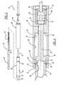
FIG. 2 is an exploded view of the anchor tool ofFIG. 1 . -
FIG.3 is a cross-section view ofFIG.2 along line 3-3 thereof. -
FIG. 4 is an enlarged cross-section view ofFIG.3 . -
FIG. 5A-5C are a schematic illustrations of positioning an anchor into a concrete structure. -
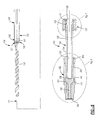
FIG. 6 is a view likeFIG. 3 of a second embodiment with the drill bit in plan view and the anchor tool in cross-section. -
FIG. 7 is an enlarged view ofFIG. 6 within circle 7. -
FIG. 8 is an enlarged view ofFIG. 6 within circle 8. -
FIG. 9A-9F are schematic illustrations of positioning an anchor into a concrete structure. -
FIG. 10 is an enlarged view ofFig. 6 withincircle 10. - The following description is merely exemplary in nature and is not intended to limit the present disclosure, application, or uses.
- Turning to the figures, an installation tool in accordance with the disclosure is illustrated and designated with the
reference numeral 10. Ahammer drill 12 is illustrated receiving theanchor installation tool 10. A nail-inanchor 14 is illustrated being secured into astructure 16. - Moving to
Figures 2 and3 , theanchor installation tool 10 is illustrated. Theinstallation tool 10 includes anelongated member 20 and ananchor guide 22. Additionally, theinstallation tool 10 can be combined with adrill bit 24. Thedrill bit 24 includes a frontfluted portion 26, and intermediate portion 23, and rear a chuckingportion 28. The intermediate portion 23 includes agroove 30 to assist in retaining theinstallation tool 10 on thedrill bit 24, as described in further detail below. The intermediate portion 23 also includes a shoulder 25 disposed at the junction between the intermediate portion 23 and thefluted portion 26, which shoulder includes a substantially flat surface 27 substantially transverse to the drill axis. The chuckingportion 28 is configured to enable thedrill bit 24 to be held in the chuck or tool holder of ahammer drill 12. In the illustrated embodiment, the chucking portion includes a hexagonal shank with a groove to position thedrill bit 24 into thehammer drill 12. However, it should be understood that the chuckingportion 28 can include other types of connectors such as a round shank, a hexagonal shank without a groove, a square shank, and/or a shank with an SDS-type connection. - The
elongated body 20 includes aninternal bore 32 extending through abody portion 34 of theelongated member 20. Thebody portion 34 generally has a desired diameter and a desired wall thickness with anopen end 35 and a closed 36 end. Theclosed end 36 of thebody member 34 includes a projectinghead 38. Thehead 38 projects substantially coaxial with thebody member 34. Theinternal bore 32 includes a first portion 33 and a second portion 31. The first and second portions 33, 31 are positioned coaxially and define a stop 29 at the transition between the first 33 and second 31 bore portions. Thehead 38 has a desired length and diameter. Ordinarily, thehead 38 is a solid portion. - A
drill bit retainer 37 is positioned near theopen end 35. Thedrill bit retainer 37 includes aball 39, and aspring clip 41. Theball 39 is seated in abore 43 in thebody portion 34. A portion of theball 39 projects through thebore 43 into bore 31. Theball 39 couples with the drill bit groove 30 to retain theinstallation tool 10 on thedrill bit 24. Theannular groove 30 is positioned a desired distance from the flat surface 27 so that when thedrill bit 24 is positioned in theanchor tool 10, the flat surface 27 of thedrill bit 24 contacts the stop 29 in theanchoring tool 10 for transferring axial movement of thedrill bit 24 to theanchoring tool 10 to provide axial movement of theanchoring tool 10, as described in greater detail below. - The
elongated member 20 is generally made out of a metallic material such as steel. The junction where thehead 38 projects from theclosed end 36 forms astop surface 40 at the end of thebody portion 34. The stop surface 40 contacts a stop surface of theanchor guide 22 as will be explained later. - The
anchor guide 22 has a sleeve-shapedbody 42. Thesleeve 42 includes aninternal bore 44 which extends through the sleeve shapedbody 42. Thebore 44 includes afirst portion 46, a reduced diameter portion 47, asecond portion 48 andend portion 50. Thefirst portion 46 is sized to fit over thebody portion 34 of theelongated member 20. The reduced diameter portion 47 is sized to fit over thehead portion 38. Astop 52 is formed at the transition between the twobore portions 46, 47. Thestop 52 provides a surface that abuts against thesurface 40 to stop further movement of theguide anchor 22 as it slides along thehead 38 andbody portions 34. - The
second bore portion 48 is on the other side of the reduced diameter portion 47. Thesecond portion 48 receives anannular magnet 53 andspacer 55. The magnet assists in retaining the anchor in thetool 10. Themagnet 53 acts as a retention member when a duply or double head nail is used as the anchor as shown inFIG. 4 . Thespacer 55 positions themagnets 53 adjacent the reduced diameter portion 47. A C-clip 57 positioned ingroove 59 holds thespacer 55 and magnet in thesecond bore portion 48. It should be understood that other types of retention members, such as an elastomeric ring or a friction fit, can be used in addition to or instead of the magnet. - An
anchor receiving member 54 is at the end of thesecond bore portion 48 beyondgroove 59. The receivingmember 54 is an enlarged bore that receives the head of theanchor 14. With the nail portion of the anchor extending into thebore 48 adjacent themagnet 53, and its head captured in the receivingmember 54 theanchor 14 is held in theanchor guide 22 so that it may be inserted into a bore in a concrete structure as seen inFIG. 5A . - Turning to
Figure 4 , an enlarged cross-sectional view of the retention mechanism is illustrated. Theretention mechanism 60 includes a groove 62 a retainingclip 64 and astop surface 66 on theanchor guide 22. Thegroove 62 is formed into the outer surface of thebody member 34. Thegroove 62 is circumferentially spaced about thebody member 34. Aretention clip 64, generally a C-clip, is positioned onto thebody member 34. Theretention clip 64 extends radially outwardly above thebody member 34 from thegroove 62 as seen inFIG. 4 . Thus, the retainingclip 64 acts as a stop when theguide member 22 is slid forward on thehead 38 and thebody member 34. Thestop surface 66 is formed at the junction of thefirst bore portion 46 and theend portion 50. Theend portion 50 has a diameter slightly smaller than thefirst bore portion 46. - A
chamfer 70 is formed at the end of theguide member 22. Thechamfer 70 enables theguide member 22 to slide over top of the C-clip 64, compressing it radially inward to move over the C-clip 64 to retain theguide 22 on thebody portion 34. Thus, after an anchor is set into the concrete structure, theguide 22 is pulled forward, towardhead 38, on thebody portion 34 until thestop surface 66 contacts theretention clip 64. In an alternative embodiment, an O-ring 65 is utilized as illustrated on the bottom half ofFig 4 . The O-ring 65 acts in the same manner to retain theguide member 22 on thebody portion 34. - A method of using the anchor installation tool to insert a nail-in
type anchor 14 is as follows. Theanchor 14 includes a front expandable portion 11 with expandable legs 19, a large diameter intermediate flange 13, and a small diameter rear head 15 that can be driven into the front expandable portion 11 to cause the legs 19 to expand. If already coupled, theanchor installation tool 10 is removed from thedrill bit 24, and thedrill bit 24 is coupled to thehammer drill 12. Thedrill bit 24 is used to drill a hole or bore into a workpiece, e.g., aconcrete structure 16, to a desired depth as illustrated inFIG. 5A . Theelongated body member 34 of thetool 10 is then positioned over the drill bit as illustrated inFIG. 3 . Additionally, theguide member 22 is extended so that thestop surface 66 engages theretention clip 64. The nail-intype anchor 14 is positioned with the rear head 15 in thesecond bore portion 48adjacent magnet 55, and a head of the insert in the receivingportion 52 of theguide 22 as seen inFIG. 5B . The front portion 11 of theanchor 14 is inserted into the concrete hole or bore as illustrated inFIG. 5B . If necessary, the hammer drill is activated to percussively pound the front portion 11 of the nail into the concrete hole or bore. The axial movement of thedrill bit 24 is transferred, via the contact of the flat surface 27 with stop 29, into axial movement of the drivingmember 34. This causes thehead portion 38 to strike the anchor head 15 to seat the front portion 11 of theanchor 14 into the workpiece. Once the front portion 11 is seated, the rear head 15 is further pounded byhead portion 38 into the front portion 11 to spread the legs 18 as illustrated inFIG. 5C . After theanchor 14 has been set, theanchor installation tool 10 is removed from the nail and thedrive guide 22 is positioned back over thehead 38 of theelongated member 20 ready for its next use. - Turning to
FIGS. 6-9F , second embodiments of aninstallation tool 110 and adrill bit 124 in accordance with the disclosure are illustrated. The reference numerals that relate to similar elements inFIGS. 1-5C have been designated with reference numerals increased by 100. - The
drill bit 124 includes a frontfluted masonry portion 126, anintermediate portion 123, and ashank portion 128. Theshank portion 128 includes a connector for connecting the drill bit to a power tool chuck or tool holder, in this embodiment an SDS-type connector 129. Ashoulder 125 is formed at the transition between thefluted portion 126 andintermediate portion 123. Theshoulder 125 includes a 45 degree chamfer adjacent theflat surface 127. Thechamfer 121 enhances the insertion into thebore 131. Asmall radius portion 119 is positioned at the transition of the cuttingportion 126 and theintermediate portion 127. The radius of thesmall radius portion 119 is approximately 0.75 mm or less. This enhances the strength of thedrill bit 124. Theshoulder 125 includes a substantiallyflat surface 127 that is oriented substantially transverse to adrill bit axis 111. Theintermediate portion 123 includes anannular groove 130 configured to releasably connect thedrill bit 124 to theinstallation tool 110. Theannular groove 130 is positioned a desired distance from theflat surface 127 so that when thedrill bit 124 is positioned in theanchoring tool 110, theflat surface 127 contacts astop 129 in theanchoring tool 110 for transferring axial movement of thedrill bit 124 to theanchoring tool 110 to provide axial movement of theanchoring tool 110, as described in greater detail below. Generally, the distance from the groove center to theflat surface 127 is between approximately 4.65 and approximately 4.85 mm. - The
anchor installation tool 110 includes an elongated drivingmember 120 and ananchor guide 122. Theelongated body 120 includes aninternal bore 132 extending through abody portion 134 of the elongated drivingmember 120. Thebody portion 134 generally has a desired diameter and a desired wall thickness with a rearopen end 135 and a forwardclosed end 136. Theinternal bore 132 includes afirst portion 133 and asecond portion 131. The first andsecond portions stop 129 at the transition between the first 133 and second 131 bore portions. Theclosed end 136 of thebody member 134 includes a forward projectinghead 138. Thehead 138 projects substantially co-axial with thebody member 134. Thehead 138 has a desired length and diameter. Ordinarily, thehead 138 is a solid portion that projects from the body. Adrill bit retainer 137 is positioned near theopen end 135. - The
retainer 137 includes anannular housing 180 supported on the openedend 135 of thebody member 134. Thehousing 180 has a sleeve configuration with an opened end and aflange end 182. Theflange end 182 defines abore 183 with a wall that rests on thebody portion 134. Abushing 184 is positioned in the open end 181 of the sleeve. Hog rings 186 retain thebushing 184 onto thebody portion 134. Additionally,hog ring 188 retains thebushing 184 onto thehousing 180. A pair oflugs 190 is held inbores 194 in thebody portion 134. Thelugs 190 have anarcuate surface 192 that seats in thegroove 130 of thedrill bit 124. Thebores 194 extend into the secondinternal bore portion 131 of thebody portion 134. Aspring band 196 biases thelugs 190. Thespring band 196 enables thelugs 190 to move radially inward and outward into theretention groove 130 of thedrill bit 124. Theretention groove 130 has anarcuate surface 192 that enables thelugs 190, viasurface 192, to be moved axially along thedrill bit 124 into and out of thegroove 130 due to the configurations of thesurfaces retention member 137 is slid on and off of thedrill bit 124. - The
elongated member 120 is generally made out of metallic material such as steel. The junction where thehead 138 projects from theclosed end 136 forms astop surface 140. Thestop surface 140 contacts a first stop surface of theanchor guide 122 as will be explained later. Additionally, the junction of the head and closed end includes asecond stop surface 141 that contacts a second stop surface of theanchor guide 122 as will be explained later. - The
anchor guide 122 has a sleeve shapedbody 142. Thesleeve 142 includes aninternal bore 144 that extends through the sleeve shapedbody 142. Thebore 144 includes afirst portion 146, asecond diameter portion 147, athird diameter portion 148, and anend portion 150. Thefirst portion 146 is sized to fit over thebody portion 134 of theelongated drive member 120. The reduceddiameter portion 147 is sized to receive anelastomeric sleeve 200. Afirst stop 152 is formed at the transition between the twobores first stop 152 provides a surface that abuts against thestop surface 140 to further stop movement of theanchor guide 122 as it slides along thehead 138 and thebody portion 134. Thethird bore portion 148 is on the other side of the reduceddiameter portion 147. Thethird bore portion 148 is sized to receive thehead portion 138 of thebody portion 134. Theend portion 150 is at the end of thethird bore 148. Theend portion 150 is an enlarged bore that receives the head of theanchor 14. The nail portion of the anchor extends intobore 148 and is received in abore 202 of theelastomeric sleeve 200. Thebore 202 is defined by awall 204 that includes a corrugated pattern, with furrows and ridges, to receive the nail portion of theanchor 14. The furrows and ridges receive the head of the nail and hold theanchor 14 in position on theguide anchor 122. - Turning to
FIG. 8 , an enlarged cross-sectional view of theanchor guide 122 is illustrated. The anchor guide includes anannular bushing 204 retained at the end of thefirst bore 146. Thebushing 204 provides asecond stop 206 that contacts thestop 141 of the junction between thehead 138 and theclosed end 136. Thebushing 204 is retained in thefirst bore 146 by ahog clip 208 that extends into agroove 210 in the wall of theanchor guide 122. - The
junction 160 of thehead 138 andbody 134 includes agroove 162 that includes an O-ring 164 that maintains smooth movement of theanchor guide 122 on thebody member 134. Thestop 141 contacts second stop 206 of thebushing 204 to prohibit furthermovement anchor guide 122 along thebody 134. Thejunction 160 has a slightly larger diameter than the rest of thebody 134. This portion providesstops anchor guide 122 as it is moved from position to position. - A method of using the
anchor installation tool 110 to insert the nail-type anchor 14 described above is illustrated inFIGS. 9A-9F . Thedrill bit 124 is inserted into the chuck of the hammer drill, and is used to drill a hole or bore into a workpiece, e.g., a concrete structure, to a desired depth as illustrated inFIG. 9A . Theelongated body member 134 of theanchor installation tool 110 is then positioned over the drill bit as illustrated inFIG. 9B . Thelugs 190, viasurface 192, slide on theintermediate surface 127. Thelugs 190 are biased byspring band 196 into thegroove 130 to lock theretention member 137 onto thedrill bit 124. Theguide member 122 is extended from thebody member 134 until thestop 144 contacts stop 206, as illustrated inFIG. 9C . The nail-intype anchor 14 is positioned with the nail portion head 15 inside thebore 202 of theelastomeric sleeve 200. Thecorrugated wall 204 holds the head 15 in theelastomeric sleeve 200, as seen inFIG. 9D . The front portion 11 of theanchor 14 is inserted into the concrete hole or bore as illustrated inFIG. 9E . If necessary, the hammer drill is activated to percussively pound the front portion 11 of theanchor 14 into the workpiece. The axial movement of thedrill bit 124 is transferred, via the contact of theflat surface 127 withstop 129, into axial movement of the drivingmember 134, which causes thehead portion 138 to strike the anchor head 15 and seat the front portion 11 of theanchor 14 in the workpiece. Next, the tool further drives the head 15 into the front expandable portion 11, causing legs 19 on the front expandable portion 11 to expand to help retain theanchor 14 in the workpiece, as shown inFig. 9F . After theanchor 14 has been set, theanchor installation tool 110 is removed from the nail and thedrive guide 122 is positioned back over thehead 138 of theelongated member 120 for its next use. - The description of the invention is merely exemplary in nature and, thus, variations that do not depart from the gist of the invention are intended to be within the scope of the invention. For example, the first embodiment of the drill bit could be used with the second embodiment of the anchor installation tool, and the second embodiment of the drill bit could be used with the first embodiment of the installation tool. In addition, either embodiment of the anchor installation tool could be used to insert and seat anchors, nails, or other fasteners other than the nail-in type anchor described above. These and other variations are not to be regarded as a departure from the spirit and scope of the invention.
Claims (11)
- An anchor installation tool comprising:an elongated driving member defining an axis and having a rear body portion and a front head portion extending frontward from the body portion and having an outer diameter that is smaller than an outer diameter of the body portion, the body portion defining an internal bore with an internal shoulder configured to receive a drill bit, the body portion further including a retaining member configured to engage with the drill bit to inhibit removal of the drill bit from the body member;an anchor guide having a sleeve body defining a bore having a rear portion sized to slidably receive the body portion of the driving member and a front portion sized to slidably receive the head portion of the driving member, the front portion further including a holding member configured to releasably hold an anchor in the front portion of the bore; anda stopping member coupled to at least one of the driving member and the anchor guide to prevent complete removal of the driving member from the anchor guide,wherein when an anchor is held in the anchor guide and a drill bit is inserted into the driving member, axial movement of the drill bit is transferred via the internal shoulder to axial movement of the driving member, which causes the head portion to strike the anchor.
- The anchor installation tool of claim 1, wherein the retaining member includes a housing on the body portion of the elongated member and a pair of biased lugs projecting through the body portion of the elongated member into a retention mechanism on the drill bit.
- The anchor installation tool of claim 2, further comprising a spring band in the housing for biasing the lugs.
- The anchor installation tool of one of claims 1-3, wherein the holding member further comprises an elastomeric sleeve.
- The anchor installation tool of claim 4, further comprising a bore in the elastomeric sleeve, the bore defines a wall that includes a corrugated pattern.
- The anchor installation tool of one of claims 1-5, further comprising a second internal coaxial bore at the rear body portion of the driving member, and a stop formed between the first and second internal bores.
- The anchor installation tool of one of claims 1-6 further comprising the drill bit, wherein the drill bit has a front cutting portion, an intermediate portion having a groove, a rear chucking portion, an a substantially transverse shoulder at a junction between the front cutting portion and the intermediate portion;
- A drill bit for an anchor installation tool comprising:a front cutting portion having at least one cutting flute,an intermediate portion having a groove configured to releasably couple the body to an anchor installation tool,a rear shank portion including a connector configured to connect the shank portion to a chuck of a drill; anda shoulder at a junction between the front cutting portion and the intermediate portion, the shoulder including a substantially flat surface oriented substantially transverse to an axis of the drill bit, the substantially flat surface spaced a desired distance from the groove so that when the drill bit is positioned in an anchor installation tool, the substantially flat surface contacts an internal shoulder in the anchor installation tool for transferring axial movement of the drill bit to the anchor installation tool.
- The drill bit of claim 8, wherein the cutting portion comprises a masonry type cutting surface, the groove comprises an annular groove, and the connector comprises a hex-shaped shank or an SDS-type connector.
- The drill bit of one of claims 8 and 9, wherein the substantially flat surface is spaced approximately 4.65 mm to approximately 4.85 mm from the groove.
- The drill bit of one of claims 8 - 10, wherein the shoulder further includes a chamfered surface or a radiused surface between the substantially flat surface and the shank portion.
Applications Claiming Priority (1)
| Application Number | Priority Date | Filing Date | Title |
|---|---|---|---|
| US12/916,972 US8602285B2 (en) | 2008-06-06 | 2010-11-01 | Anchor installation tool |
Publications (2)
| Publication Number | Publication Date |
|---|---|
| EP2447008A2 true EP2447008A2 (en) | 2012-05-02 |
| EP2447008A3 EP2447008A3 (en) | 2016-08-17 |
Family
ID=45033697
Family Applications (1)
| Application Number | Title | Priority Date | Filing Date |
|---|---|---|---|
| EP11184716.6A Withdrawn EP2447008A3 (en) | 2010-11-01 | 2011-10-11 | Anchor installation tool |
Country Status (3)
| Country | Link |
|---|---|
| US (2) | US8602285B2 (en) |
| EP (1) | EP2447008A3 (en) |
| CN (1) | CN202467214U (en) |
Cited By (1)
| Publication number | Priority date | Publication date | Assignee | Title |
|---|---|---|---|---|
| DE102020122156A1 (en) | 2020-08-25 | 2022-03-03 | Philip Alexander Goerentz | Tool for setting an anchor nail |
Families Citing this family (27)
| Publication number | Priority date | Publication date | Assignee | Title |
|---|---|---|---|---|
| US8061000B2 (en) * | 2008-06-06 | 2011-11-22 | Black & Decker Inc. | Anchor installation tool |
| US8602285B2 (en) * | 2008-06-06 | 2013-12-10 | Black & Decker | Anchor installation tool |
| DE102010030433A1 (en) * | 2010-06-23 | 2011-12-29 | Robert Bosch Gmbh | Hand tool with a striking mechanism |
| US9975232B2 (en) | 2012-02-27 | 2018-05-22 | Milwaukee Electric Tool Corporation | Pin anchor driver |
| DE102012221114B3 (en) * | 2012-11-19 | 2014-04-10 | Hilti Aktiengesellschaft | Setting tool for impact anchors |
| US10603768B2 (en) | 2013-03-15 | 2020-03-31 | Omg, Inc. | Installation tool/fastener system for roof truss framing and construction |
| CA2903804C (en) * | 2013-03-15 | 2019-04-23 | Handy & Harman | Fastener installation tool for roof truss framing and construction system |
| US11433511B2 (en) | 2013-03-15 | 2022-09-06 | Omg, Inc. | Dual positionable fastener installation tool adaptor |
| US9573260B2 (en) * | 2013-05-08 | 2017-02-21 | Arthur R. Walters, JR. | Fastening device for driving double-headed fasteners |
| US9364903B2 (en) * | 2013-10-11 | 2016-06-14 | Irwin Industrial Tool Company | Drilling apparatus and method |
| US20150290498A1 (en) * | 2014-04-14 | 2015-10-15 | Bradly W. Bussewitz | Tree step including an integrated shank |
| CN105364765B (en) * | 2014-08-28 | 2018-01-19 | 南京德朔实业有限公司 | Torsion exports instrument |
| EP3206838B1 (en) * | 2014-10-13 | 2018-12-19 | Mercator Innovations BVBA | Combination screwdriver and torquelimiting system |
| CN105625728A (en) * | 2014-11-05 | 2016-06-01 | 天津银龙预应力材料股份有限公司 | Rapid mounting tool for anchor plate |
| JP6440118B2 (en) * | 2015-03-10 | 2018-12-19 | パナソニックIpマネジメント株式会社 | Impact rotary tool |
| WO2016161523A1 (en) * | 2015-04-10 | 2016-10-13 | Robert Cousineau | Setting tool fastening system |
| TWM551535U (en) * | 2015-12-10 | 2017-11-11 | 米沃奇電子工具公司 | Bit holder assembly |
| US20180133880A1 (en) * | 2016-11-16 | 2018-05-17 | Schley Products, Inc. | Quick change pneumatic hammer |
| US10300588B2 (en) * | 2016-11-30 | 2019-05-28 | Andrew S. Pauba | Method of setting a drop-in anchor |
| US11105356B2 (en) | 2016-11-30 | 2021-08-31 | Andrew S. Pauba | Drop-in anchor setting tool |
| IT201600131235A1 (en) * | 2016-12-27 | 2018-06-27 | Automotive Lighting Italia Spa | SELF-POWERED AUTOMATIC SCREWDRIVER |
| EP3424643A1 (en) * | 2017-07-05 | 2019-01-09 | HILTI Aktiengesellschaft | Setting tool, set for a set tool system and set tool system |
| USD907452S1 (en) | 2017-07-25 | 2021-01-12 | Milwaukee Electric Tool Corporation | Drive guide |
| EP3434417B1 (en) | 2017-07-25 | 2021-02-17 | Milwaukee Electric Tool Corporation | Drive guide |
| CA3133057A1 (en) * | 2019-04-15 | 2020-10-22 | Inventio Ag | Setting tool and method for percussively driving an anchor rod into a borehole |
| AU2021224080A1 (en) * | 2020-02-17 | 2022-10-13 | Steven Scott Valdezate | Driver for nail anchor |
| US20220212327A1 (en) * | 2021-01-07 | 2022-07-07 | Eric Vilandre | Hammer Drill Driving Bit Device |
Family Cites Families (118)
| Publication number | Priority date | Publication date | Assignee | Title |
|---|---|---|---|---|
| US1089112A (en) * | 1913-06-30 | 1914-03-03 | Oscar Z Coutant | Tool. |
| US1697414A (en) * | 1927-06-02 | 1929-01-01 | Cordray Lee Roy | Reversible tool-chuck-supporting means |
| US1765729A (en) * | 1928-01-13 | 1930-06-24 | Morte William F La | Strut used in concrete fireproofing |
| US1925385A (en) * | 1932-11-08 | 1933-09-05 | Homer C Humes | Screw driver with screw holders |
| US2093261A (en) * | 1936-06-13 | 1937-09-14 | Brick V Neer Sales Company | Building wall structure |
| US2114451A (en) * | 1936-11-02 | 1938-04-19 | Lee H Mattes | Building covering construction |
| US2445674A (en) * | 1945-03-03 | 1948-07-20 | Willard E Kendall | Pneumatic nail driver |
| US2543942A (en) * | 1947-11-08 | 1951-03-06 | Keller Tool Co | Power-operated nail driver |
| US2575079A (en) * | 1949-05-13 | 1951-11-13 | Temple Velocity Equipment Inc | Explosively driven stud with knockoff head portion |
| US2641379A (en) * | 1950-05-31 | 1953-06-09 | Barbaro Joseph | Method of relining brakes |
| US2638591A (en) * | 1951-04-06 | 1953-05-19 | Lewis S Harris | Nail holding and positioning device |
| US3161242A (en) * | 1960-05-31 | 1964-12-15 | Skil Corp | Rotary-hammer devices and tool element accessories therefor |
| US3042004A (en) * | 1960-07-08 | 1962-07-03 | Chicago Pneuamtic Tool Company | Nail driving attachment for pneumatic tool |
| US3177952A (en) * | 1961-08-08 | 1965-04-13 | Cambridge Thermionic Corp | Impact tool |
| US3163865A (en) * | 1961-09-13 | 1965-01-05 | Port Clinton Mfg Company | Drive tool |
| US3136347A (en) * | 1962-10-15 | 1964-06-09 | Greenlee Bros & Co | Drill bit shank |
| DE1478856C3 (en) * | 1965-03-03 | 1973-10-04 | Dibotec Ag, Zuerich (Schweiz) | Attachment for driving in self-drilling anchors |
| US3336611A (en) * | 1966-03-01 | 1967-08-22 | Henry A Harry | Combination rotary tools |
| US3503549A (en) * | 1967-09-29 | 1970-03-31 | Olin Mathieson | Muzzle bushing for piston-type power-actuated tool |
| US3534640A (en) * | 1968-05-16 | 1970-10-20 | Gen Electro Mech Corp | Tool coupling device |
| GB1272771A (en) * | 1968-08-08 | 1972-05-03 | Avdel Ltd | Fastener placing apparatus |
| DE1775730A1 (en) * | 1968-09-17 | 1971-08-05 | Hilti Ag | Nail for corrosion-resistant fastenings |
| US3579677A (en) * | 1969-02-07 | 1971-05-25 | Ullman Devices Corp | Flexible rotary compound tool |
| US3602419A (en) * | 1969-09-29 | 1971-08-31 | Morris Doberne | Pneumatically operated nail driver |
| US3631747A (en) * | 1970-03-20 | 1972-01-04 | Grove Valve & Regulator Co | Stud driver |
| US3791660A (en) * | 1973-01-09 | 1974-02-12 | Bendix Corp | Device for gripping, driving and supplying coolant to a cutting tool having coolant passages therein |
| GB1462172A (en) * | 1973-01-12 | 1977-01-19 | Avdel Ltd | Fastener placing apparatus |
| US3847193A (en) * | 1973-06-29 | 1974-11-12 | Hi Tor Inventions Corp | Nail-screw holder |
| US3965510A (en) * | 1975-05-09 | 1976-06-29 | Illinois Tool Works Inc. | Combination drilling and wrenching tool |
| US4006996A (en) * | 1975-12-01 | 1977-02-08 | The Precise Corporation | Positively driven tool holder for a high speed rotatable spindle |
| US4007795A (en) * | 1976-02-13 | 1977-02-15 | Skil Corporation | Attachment for a rotary-hammer tool |
| US4127000A (en) * | 1977-02-07 | 1978-11-28 | Kennametal Inc. | Method and apparatus for installing chemical anchor bolt assemblies in earth formations |
| US4107800A (en) * | 1977-06-13 | 1978-08-22 | Illinois Tool Works Inc. | Combination drilling and wrenching tool |
| US4201072A (en) * | 1978-12-20 | 1980-05-06 | Snell John H | Tool for installation of toggle-screw anchors |
| US4218795A (en) * | 1979-03-07 | 1980-08-26 | Illinois Tool Works Inc. | Drill bit with fastener-driving collar assembly |
| US4289010A (en) * | 1980-05-12 | 1981-09-15 | Dale R. Badger | Universal adapter for screw anchor installation |
| US4551875A (en) * | 1980-10-23 | 1985-11-12 | International Telephone And Telegraph Corporation | Combination tool |
| US4367778A (en) * | 1980-10-28 | 1983-01-11 | Ray Bradbury | Nail driver accessor having a nail holder mechanism |
| US4448339A (en) * | 1981-12-03 | 1984-05-15 | Ronald Pettigrew | Nail driving and recessing tool |
| US4468826A (en) * | 1982-06-11 | 1984-09-04 | Black & Decker Inc. | Hammer-drill for masonry fasteners |
| US4573839A (en) * | 1982-08-16 | 1986-03-04 | Danny Finnegan | Mounting chuck for a drill having reversible tools therein |
| US4422489A (en) * | 1982-10-22 | 1983-12-27 | Gary Ross | Combination nail holder, nail shield, and nail finishing set |
| US4512693A (en) * | 1982-12-27 | 1985-04-23 | Swanson Carl A | Reversible drill and drive tool holder |
| US4890779A (en) * | 1984-08-23 | 1990-01-02 | Giannuzzi Louis | Automatic setting tool for masonry anchors |
| US4637539A (en) * | 1984-09-10 | 1987-01-20 | Turcott James L | Anchor bolt installation tool with depth stop |
| US4676424A (en) * | 1986-02-10 | 1987-06-30 | Meador A Leon | Nail guiding and driving tool |
| US4676703A (en) * | 1986-04-28 | 1987-06-30 | Swanson Carl A | Reversible drill and drive tool holder |
| US4709841A (en) * | 1986-06-09 | 1987-12-01 | Phillips Plastics Corporation | Tool for installing expandable fastener |
| US4982625A (en) * | 1986-11-10 | 1991-01-08 | A.T. & G. Company, Inc. | Adaptor and driver for an adhesive capsule anchor |
| US4818157A (en) * | 1986-12-31 | 1989-04-04 | James E. Scapillato | Quick-change adapter and tools for use with the adapter |
| US4791690A (en) * | 1987-04-20 | 1988-12-20 | Kuang Wu Huang | Combination drill bit and socket drive assembly |
| US4899431A (en) * | 1988-06-13 | 1990-02-13 | Borntrager Harvey S | Anchor setting tool |
| US4867249A (en) * | 1988-08-16 | 1989-09-19 | Watkins Jr Rex A | Driving and setting tool |
| US5011344A (en) * | 1988-12-01 | 1991-04-30 | Tapmatic Corporation | Positive drive adapter |
| US5062749A (en) * | 1989-02-21 | 1991-11-05 | Sheets Harold D | Tool coupler |
| DE3907088A1 (en) * | 1989-02-27 | 1990-11-08 | Fischer Artur Werke Gmbh | DRILL |
| DE8903996U1 (en) | 1989-04-01 | 1990-08-02 | Fischer-Werke Artur Fischer Gmbh & Co Kg, 7244 Waldachtal, De | |
| DE3914512A1 (en) | 1989-05-02 | 1990-11-08 | Fischer Artur Werke Gmbh | Hammering device for impact anchor - comprises drill inside sliding sleeve whose upper end is in contact with impact disc |
| DE3916611A1 (en) * | 1989-05-22 | 1990-11-29 | Fischer Artur Werke Gmbh | DRIVING DEVICE FOR IMPACT ANCHORS WITH SPREADING SLEEVE |
| US4995768A (en) * | 1989-07-31 | 1991-02-26 | Ralph Craft | Rapid change drill holder assembly |
| DE68910972T2 (en) * | 1989-09-08 | 1994-03-24 | Miyanaga Miku Kk | Setting tool for expansion anchors. |
| US4954025A (en) * | 1990-01-16 | 1990-09-04 | Diversified Fastening Systems, Inc. | Anchor set tool |
| US5011354A (en) * | 1990-02-28 | 1991-04-30 | Brownlee Ritch J | Concrete fastener apparatus |
| DE4008750A1 (en) * | 1990-03-19 | 1991-09-26 | Hilti Ag | Fixing device-driving tool - incorporates rotary drill and bolt-setting mechanism |
| US5165588A (en) * | 1990-06-11 | 1992-11-24 | Rowland Donald S | Nail driver and nail |
| US5184385A (en) * | 1990-07-03 | 1993-02-09 | Valesh Michael L | Retainer pin remover |
| US5038435A (en) * | 1990-12-10 | 1991-08-13 | Diversified Fastening Systems, Inc. | Anchor set tool |
| US5142954A (en) * | 1991-05-31 | 1992-09-01 | Emhart, Inc. | Masonry anchor installation tool |
| DE9110513U1 (en) | 1991-08-24 | 1992-12-24 | Fischerwerke Artur Fischer Gmbh & Co Kg, 7244 Waldachtal, De | |
| US5405221A (en) * | 1992-12-30 | 1995-04-11 | Ducker, Iii; Andrew L. | Gyro-stabilized tool bit with wide, removable mounting adaptor for use in a wide mouth chuck |
| US5470180A (en) * | 1994-05-02 | 1995-11-28 | Jore; Matthew B. | Reversible drill/driver tool |
| US5588788A (en) * | 1994-07-07 | 1996-12-31 | Dominguez; Armando | Double headed fastener |
| US5481949A (en) * | 1994-08-15 | 1996-01-09 | Yen; En-Ji | Locking member for use in hand tools |
| DE29507697U1 (en) | 1995-05-10 | 1995-07-20 | Upat Max Langensiepen Kg | Driving tool for a wire holder |
| DE29518109U1 (en) * | 1995-11-15 | 1997-03-13 | Fischer Artur Werke Gmbh | Device for mounting an impact anchor |
| US5711043A (en) * | 1996-10-08 | 1998-01-27 | Diversified Fastening Systems, Inc. | Set tool and cap |
| US5918789A (en) * | 1997-09-12 | 1999-07-06 | Illinois Tool Works Inc. | Fastner collation tube for stand-up fastener driving tool |
| US5979913A (en) * | 1998-05-19 | 1999-11-09 | Kosik; Thomas | Universal driving and setting tool and method of using same |
| US6053675A (en) * | 1998-06-26 | 2000-04-25 | Black & Decker Inc. | Quick-acting tool bit holder |
| US6062789A (en) * | 1998-09-12 | 2000-05-16 | Pope; Larry D. | Nail with tapered formed bushing |
| DE19904849A1 (en) | 1999-02-08 | 2000-08-17 | Gerhard Lauger | Nail driving-in device, with receiving device for nail having one end connected to connecting piece for hammering machine |
| AU4902200A (en) * | 1999-05-03 | 2000-11-17 | Maxtech Manufacturing Inc. | Quick-connect mechanism |
| CA2270805A1 (en) * | 1999-05-03 | 2000-11-03 | Andre Lamarre | Setting tool |
| US6520509B1 (en) * | 1999-08-13 | 2003-02-18 | Maxtech Manufacturing Inc. | Screw guide device with drill bit/screw bit and counter sink/drill stop means |
| US6223375B1 (en) * | 1999-08-24 | 2001-05-01 | Illinois Tool Works Inc | Drilling and fastener driving tool |
| US6220122B1 (en) * | 1999-10-20 | 2001-04-24 | Illinois Tool Works Inc | Fastener holding tool and system |
| US6457926B1 (en) * | 1999-12-06 | 2002-10-01 | Larry D. Pope | Screw with tapered formed bushing |
| DE10000059A1 (en) | 2000-01-03 | 2001-10-18 | Peter Kellner | Fastener for fixing faade elements on walls comprises plate holder with coil shaped part with tubular shaft and two plates and connected to positioning sleeve with openings for guiding through dowel sleeve |
| US20020124371A1 (en) * | 2001-01-25 | 2002-09-12 | Livingston Robert A. | Anchor driver tool for power hammer apparatus |
| US20040056435A1 (en) * | 2001-02-15 | 2004-03-25 | Sanjeev Bedi | Quick-connect mechanism |
| US6585143B1 (en) * | 2001-03-05 | 2003-07-01 | John M. Schultz | Anchor setting device |
| US20020194718A1 (en) * | 2001-06-21 | 2002-12-26 | David Yekutiely | Anchoring system and methods therefor |
| EP1273396B1 (en) * | 2001-07-06 | 2009-12-30 | Robert Bosch Gmbh | Chisel resp. drill bit |
| EP1281481A3 (en) | 2001-08-03 | 2005-08-03 | fischerwerke Artur Fischer GmbH & Co. KG | Tool for placing an anchor bolt |
| US6928778B2 (en) * | 2001-08-03 | 2005-08-16 | Ben L. Schmid | Stucco anchorage nail |
| US6668941B2 (en) * | 2001-11-28 | 2003-12-30 | Credo Technology Corporation | Screw holding and driving device |
| US6935821B2 (en) * | 2002-04-05 | 2005-08-30 | Illinois Tool Works, Inc. | Mushrooming expandable anchor |
| TW542030U (en) * | 2002-11-19 | 2003-07-11 | Jie-Ren Shiau | Pivot type dual head tool set |
| DE20218422U1 (en) | 2002-11-28 | 2004-04-08 | Fischerwerke Artur Fischer Gmbh & Co. Kg | Holder for fastening of insulating slab on foundation has hammer pin with drill socket with diameter which corresponds to outside diameter of expansion section, with hammer pin and expansion nail in one piece |
| US20040134312A1 (en) * | 2003-01-14 | 2004-07-15 | Hodges Shawn Carl | Concrete anchor installation tool for use to install overhead a concrete drive anchor with or without pretied wires, from the floor, for suspension of tubing, suspended ceilings or other items |
| US7065855B2 (en) * | 2003-02-25 | 2006-06-27 | Textron Inc. | Installation tool for setting anchors |
| US7127972B2 (en) * | 2003-03-05 | 2006-10-31 | Klein David T | Method and apparatus for attaching a rod member to a remote surface |
| US6848346B1 (en) * | 2003-07-09 | 2005-02-01 | Illinois Tool Work Inc | Hurricane shutter fastener installation bit |
| US7237987B2 (en) * | 2003-08-08 | 2007-07-03 | Alltrade Tools Llc | Reversible drill and drive tool |
| US6915936B2 (en) * | 2003-09-05 | 2005-07-12 | Matrix Tool, Inc. | Tool for installing nail-pin anchors and anchor bolts |
| US7141074B2 (en) * | 2003-09-17 | 2006-11-28 | Depuy Spine, Inc. | Variable depth drill with self-centering sleeve |
| US7354230B2 (en) * | 2003-12-23 | 2008-04-08 | Lynn Bauman | Bit holding apparatus for use with a power tool |
| EP1708852A4 (en) * | 2004-01-28 | 2008-09-03 | M G H Agricultural Cooperative | Nail guide |
| US7121357B1 (en) * | 2004-08-30 | 2006-10-17 | Richard Raimondi | Method of inserting a grounding rod |
| US20060048611A1 (en) * | 2004-09-07 | 2006-03-09 | Illinois Tool Works | Panel fastening and waterproofing anchor |
| SE528783C2 (en) * | 2004-10-05 | 2007-02-13 | Seco Tools Ab | Tools where the tip and holder have radial support surfaces |
| US20060213014A1 (en) * | 2005-03-28 | 2006-09-28 | Manske David R | Multipurpose tool |
| US7404563B2 (en) | 2006-02-28 | 2008-07-29 | Alltrade Tools Llc | Reversible drill and drive tool II |
| US7669860B2 (en) * | 2006-07-27 | 2010-03-02 | Hsin Ying Enterprise Co., Ltd. | Tool retaining or connecting device |
| US7814631B2 (en) | 2007-01-22 | 2010-10-19 | Thomas Allan Wallek | Expansion anchor setting apparatus |
| US8602285B2 (en) * | 2008-06-06 | 2013-12-10 | Black & Decker | Anchor installation tool |
| US8061000B2 (en) * | 2008-06-06 | 2011-11-22 | Black & Decker Inc. | Anchor installation tool |
| GB2463346B (en) * | 2008-09-11 | 2012-05-30 | Black & Decker Inc | Anchor installation tool |
-
2010
- 2010-11-01 US US12/916,972 patent/US8602285B2/en active Active
-
2011
- 2011-10-11 EP EP11184716.6A patent/EP2447008A3/en not_active Withdrawn
- 2011-11-01 CN CN2011204259619U patent/CN202467214U/en not_active Expired - Fee Related
-
2013
- 2013-06-04 US US13/909,396 patent/US20130266388A1/en not_active Abandoned
Cited By (1)
| Publication number | Priority date | Publication date | Assignee | Title |
|---|---|---|---|---|
| DE102020122156A1 (en) | 2020-08-25 | 2022-03-03 | Philip Alexander Goerentz | Tool for setting an anchor nail |
Also Published As
| Publication number | Publication date |
|---|---|
| US8602285B2 (en) | 2013-12-10 |
| EP2447008A3 (en) | 2016-08-17 |
| US20110089218A1 (en) | 2011-04-21 |
| US20130266388A1 (en) | 2013-10-10 |
| CN202467214U (en) | 2012-10-03 |
Similar Documents
| Publication | Publication Date | Title |
|---|---|---|
| US8602285B2 (en) | Anchor installation tool | |
| US8061000B2 (en) | Anchor installation tool | |
| US9731356B2 (en) | Tool connector having multiple seating positions | |
| US6261035B1 (en) | Chuck, bit, assembly thereof and methods of mounting | |
| US3060440A (en) | Fastener driving tools | |
| US7121774B2 (en) | Clamping device for hexagon bits | |
| US10513017B2 (en) | Drive guide for fastening bits | |
| US4519536A (en) | Apparatus for driving nails using an impact hammer | |
| AU2014240356B2 (en) | Drilling Apparatus and Method | |
| CN215615188U (en) | Multi-size tool bit holder | |
| US8733216B1 (en) | Depth setter bit holder | |
| US20020067008A1 (en) | Chuck for a boring tool | |
| EP0611074A1 (en) | Hammer-strikable, powder-actuated fastener-driving tool | |
| US6951153B2 (en) | Nail guiding and driving tool | |
| US20060254394A1 (en) | Fastener driver | |
| EP1795307A3 (en) | Power impact tool adapter | |
| TWM551535U (en) | Bit holder assembly | |
| US9975232B2 (en) | Pin anchor driver | |
| US5711043A (en) | Set tool and cap | |
| AU2003231723B2 (en) | Stabilizing magazine follower for fastener driving tool | |
| GB2463346A (en) | Anchor installation tool with pivoting body | |
| GB2411373A (en) | Fastner retaining device | |
| CN112739481A (en) | Hole saw assembly | |
| US6381788B2 (en) | Nailing tool capable of initially starting a connecting member with a tip | |
| TW200624227A (en) | Clamped structure of screwdriver head |
Legal Events
| Date | Code | Title | Description |
|---|---|---|---|
| PUAI | Public reference made under article 153(3) epc to a published international application that has entered the european phase |
Free format text: ORIGINAL CODE: 0009012 |
|
| AK | Designated contracting states |
Kind code of ref document: A2 Designated state(s): AL AT BE BG CH CY CZ DE DK EE ES FI FR GB GR HR HU IE IS IT LI LT LU LV MC MK MT NL NO PL PT RO RS SE SI SK SM TR |
|
| AX | Request for extension of the european patent |
Extension state: BA ME |
|
| PUAL | Search report despatched |
Free format text: ORIGINAL CODE: 0009013 |
|
| AK | Designated contracting states |
Kind code of ref document: A3 Designated state(s): AL AT BE BG CH CY CZ DE DK EE ES FI FR GB GR HR HU IE IS IT LI LT LU LV MC MK MT NL NO PL PT RO RS SE SI SK SM TR |
|
| AX | Request for extension of the european patent |
Extension state: BA ME |
|
| RIC1 | Information provided on ipc code assigned before grant |
Ipc: B25B 21/00 20060101ALI20160712BHEP Ipc: B25B 31/00 20060101AFI20160712BHEP Ipc: B23B 41/00 20060101ALI20160712BHEP Ipc: B23B 51/08 20060101ALI20160712BHEP Ipc: B25B 23/00 20060101ALI20160712BHEP Ipc: B25C 7/00 20060101ALI20160712BHEP Ipc: B25D 17/00 20060101ALI20160712BHEP |
|
| 17P | Request for examination filed |
Effective date: 20160901 |
|
| RBV | Designated contracting states (corrected) |
Designated state(s): AL AT BE BG CH CY CZ DE DK EE ES FI FR GB GR HR HU IE IS IT LI LT LU LV MC MK MT NL NO PL PT RO RS SE SI SK SM TR |
|
| 17Q | First examination report despatched |
Effective date: 20180206 |
|
| STAA | Information on the status of an ep patent application or granted ep patent |
Free format text: STATUS: THE APPLICATION IS DEEMED TO BE WITHDRAWN |
|
| 18D | Application deemed to be withdrawn |
Effective date: 20180619 |