EP3195295B1 - Omni-directional shoulder assembly for crash test dummy - Google Patents
Omni-directional shoulder assembly for crash test dummy Download PDFInfo
- Publication number
- EP3195295B1 EP3195295B1 EP15774790.8A EP15774790A EP3195295B1 EP 3195295 B1 EP3195295 B1 EP 3195295B1 EP 15774790 A EP15774790 A EP 15774790A EP 3195295 B1 EP3195295 B1 EP 3195295B1
- Authority
- EP
- European Patent Office
- Prior art keywords
- shoulder
- assembly
- ball
- crash test
- test dummy
- Prior art date
- Legal status (The legal status is an assumption and is not a legal conclusion. Google has not performed a legal analysis and makes no representation as to the accuracy of the status listed.)
- Active
Links
Images







Classifications
-
- G—PHYSICS
- G09—EDUCATION; CRYPTOGRAPHY; DISPLAY; ADVERTISING; SEALS
- G09B—EDUCATIONAL OR DEMONSTRATION APPLIANCES; APPLIANCES FOR TEACHING, OR COMMUNICATING WITH, THE BLIND, DEAF OR MUTE; MODELS; PLANETARIA; GLOBES; MAPS; DIAGRAMS
- G09B23/00—Models for scientific, medical, or mathematical purposes, e.g. full-sized devices for demonstration purposes
- G09B23/28—Models for scientific, medical, or mathematical purposes, e.g. full-sized devices for demonstration purposes for medicine
- G09B23/288—Models for scientific, medical, or mathematical purposes, e.g. full-sized devices for demonstration purposes for medicine for artificial respiration or heart massage
-
- G—PHYSICS
- G09—EDUCATION; CRYPTOGRAPHY; DISPLAY; ADVERTISING; SEALS
- G09B—EDUCATIONAL OR DEMONSTRATION APPLIANCES; APPLIANCES FOR TEACHING, OR COMMUNICATING WITH, THE BLIND, DEAF OR MUTE; MODELS; PLANETARIA; GLOBES; MAPS; DIAGRAMS
- G09B23/00—Models for scientific, medical, or mathematical purposes, e.g. full-sized devices for demonstration purposes
- G09B23/28—Models for scientific, medical, or mathematical purposes, e.g. full-sized devices for demonstration purposes for medicine
- G09B23/30—Anatomical models
- G09B23/32—Anatomical models with moving parts
Definitions
- the present invention relates to a shoulder assembly for a crash test dummy, according to the preamble part of claim 1.
- a shoulder assembly is known from US 2014/190279 A1 .
- Automotive, aviation, and other vehicle manufacturers conduct a wide variety of collision testing to measure the effects of a collision on a vehicle and its occupants.
- collision testing a vehicle manufacturer gains valuable information that can be used to improve the vehicle, authorities examine vehicles to submit type approval, and consumer organizations provide information on vehicle safety ratings to the public.
- Collision testing often involves the use of anthropomorphic test devices, better known as "crash test dummies", to estimate a human's injury risk.
- the dummy must possess the general mechanical properties, dimensions, masses, joints, and joint stiffness of the humans of interest. In addition, they must possess sufficient mechanical impact response similitude and sensitivity to cause them to interact with the vehicle's interior in a human-like manner.
- the crash test dummy typically includes a head assembly, spine assembly (including neck), rib cage assembly, abdomen, pelvis assembly, right and left arm assemblies, and right and left leg assemblies.
- the arm assembly has an upper arm assembly and a lower arm assembly.
- the upper arm assembly is typically connected to a shoulder assembly, which, in turn, is typically connected to the spine assembly.
- the present invention is a shoulder assembly for a crash test dummy according to claim 1.
- a new omni-directional shoulder assembly is provided for a crash test dummy.
- the omni-directional shoulder assembly provides for a human range of motion in all three axes of a shoulder joint for the crash test dummy.
- the omni-directional shoulder assembly includes a non-rigidly mounted scapula and clavicle that are free to move in three-dimensional space for the crash test dummy.
- the omni-directional shoulder assembly includes a humerus bone attached with a ball joint and the bone is made of a plastic material to mimic human skeletal weight and strength for the crash test dummy.
- the omnidirectional shoulder assembly is a surrogate to mimic human responses in a vehicle safety restraint system for different modes of impact during vehicle crashes for the crash test dummy.
- the crash test dummy 12 is of a 10.5 year old child and is illustrated in a standing position. This crash test dummy 12 is used primarily to test the performance of automotive interiors and restraint systems for front and rear seat occupants.
- the size and weight of the crash test dummy 12 are based on anthropometric studies, which are typically done separately by the following organizations, University of Michigan Transportation Research Institute (UMTRI), U.S. Military Anthropometry Survey (ANSUR), and Civilian American and European Surface Anthropometry Resource (CESAR). It should be appreciated that ranges of motions, centers of gravity, and segment masses simulate those of human subjects defined by the anthropometric data.
- the crash test dummy 12 includes a head assembly, generally indicated at 14.
- the crash test dummy 12 also includes a spine assembly, generally indicated at 15, ( FIG. 2 ) having an upper end mounted to the head assembly 14 and a lower end extending into a torso area of the crash test dummy 12.
- the spine assembly 15 includes a neck (not shown) attached to the head assembly 14.
- the torso area of the crash test dummy 12 also includes a rib cage or torso assembly, generally indicated at 16, connected to the spine assembly 15.
- the crash test dummy 12 also has a pair of arm assemblies including a right arm assembly, generally indicated at 18, and a left arm assembly, generally indicated at 20, which are attached to the crash test dummy 12 via an omnidirectional shoulder assembly 30, according to the present invention, to be described.
- a lower end of the spine assembly 15 is connected to a lumbar-thoracic adapter (not shown), which is connected to a lumbar to pelvic adapter (not shown).
- the crash test dummy 12 includes a pelvis assembly, generally indicated at 22, connected to the adapter.
- the crash test dummy 12 also includes a right leg assembly 24 and a left leg assembly 26, which are attached to the pelvis assembly 22.
- various components of the crash test dummy 12 may be covered in a polyvinyl skin such as a flesh and skin assembly, generally indicated at 28 and partially shown, for biofidelity of the crash test dummy 12.
- an omni-directional shoulder assembly 30, is shown for the crash test dummy 12.
- the shoulder assembly 30 can be used on both the right hand and left hand positions of the crash test dummy 12 with different parts mirrored on a mid-sagittal plane.
- one shoulder assembly 30 is on the right hand position of the crash test dummy 12 and another shoulder assembly 30 is on the left hand position of the crash test dummy 12. Since the shoulder assembly 30 is symmetric for each of the right hand and left hand positions of the crash test dummy 12, only one shoulder assembly 30 will be subsequently described. It should be appreciated that the subsequent description of the shoulder assembly 30 is the same for both the right hand and left hand positions of the crash test dummy 12.
- the shoulder assembly 30 is connected to the spine assembly 15.
- the spine assembly 15 includes a neck (not shown) connected to the head assembly 14 and a spine box 32 connected to the neck.
- the neck has a lower end connected to by a suitable attachment such as one or more fasteners (not shown) to the spine box 32.
- fasteners threadably engage apertures (not shown) in the spine box 32 to secure the neck to the spine box 32.
- the torso assembly 16 includes a sternum 34 spaced forwardly from the spine box 32.
- the sternum 34 is generally rectangular in shape, but may be any suitable shape.
- the torso assembly 16 also includes one or more ribs 36 extending between the spine box 32 and sternum 34.
- the ribs 36 are generally arcuate in shape and generally rectangular in cross-sectional shape, but may be any suitable shape.
- the ribs 36 are vertically spaced along the spine box 32 and sternum 34.
- the ribs 36 are connected to the spine box 32 and sternum 34 by a suitable mechanism such as one or more fasteners 38.
- the shoulder assembly 30 includes a pair of scapulas 40 connected to the spine box 32.
- the scapulas 40 are generally triangular and arcuate in shape.
- the scapulas 40 are made of a plastic material such as polyurethane.
- the scapulas 40 have one end mounted to one or more mounting members 41 of the spine box 32 by a suitable mechanism such as one or more fasteners 42.
- the mounting members 41 are generally rectangular in shape, but may be any suitable shape.
- the mounting members 41 are made of an elastomeric material such as rubber.
- the mounting members 41 are mounted to the spine box 32 by one or more fasteners 38.
- the scapulas 40 are non-rigidly mounted to the spine box 32 via the mounting members 41 such that the scapulas 40 are free to move in three-dimensional space. It should be appreciated that the scapula 40 has the ability to slide freely and is not rigidly affixed to the spine box 32. It should also be appreciated that the mounting members 41 allow the scapulas 40 to slide over the ribs 36 without contacting them.
- the shoulder assembly 30 also includes a pair of mounting brackets 44 at one end of the scapulas 40 and connected to the scapulas 40 by a suitable mechanism such as fasteners 46.
- the mounting bracket 44 is made of a metal material such as steel and aluminum.
- the shoulder assembly 30 also includes a pair of clavicles 48 mounted to the sternum 34 and to one or more mounting members 45 of the mounting brackets 44 by a suitable mechanism such as fasteners 50.
- the mounting members 45 are generally rectangular in shape, but may be any suitable shape.
- the mounting members 45 are made of an elastomeric material such as rubber.
- the clavicles 48 are generally cylindrical in shape and extend transversely across the torso.
- the clavicles 48 are non- rigidly mounted via the mounting members 45 to the mounting brackets 44 such that the clavicles 48 are free to move in three-dimensional space. It should be appreciated that the clavicles 48 have a free range of motion and are not rigidly attached to the sternum 34.
- an impact on the shoulder assembly 30 of the crash test dummy 12 would move the shoulder assembly 30 towards the spine assembly 15.
- the shoulder assembly 30 is supported only by the scapula 40 and clavicle 48.
- the mounting members 41 and 45 would shear and stretch towards the spine assembly 15 which, in turn, would allow the scapula 40 to slide over the ribs 36 without any contact being applied to the ribs 36.
- the scapula 40 and clavicle 48 are attached to the spine assembly 15 and sternum 34, the mounting members 41 and 45 allow for movement of the scapula 40 and clavicle 48 without having any or minimal movement to the remainder of the crash test dummy 12.
- the shoulder assembly 30 also includes a shoulder cup member 52 mounted to the mounting bracket 44.
- the shoulder cup member 52 is generally cylindrical in shape and extends laterally.
- the shoulder cup member 52 has a socket 54 extending axially therein to form a shoulder ball joint.
- the socket 54 is generally hemi-spherical in shape.
- the shoulder cup member 52 also has an aperture 55 extending from a bottom of the socket 54 axially therethrough.
- the shoulder cup member 52 is made of a metal material such as steel and aluminum.
- the shoulder cup member 52 is connected to the mounting bracket 44 by a suitable mechanism such as fasteners 56.
- the shoulder assembly 30 also includes a pair of breastplates 58 connected to the clavicles 48.
- the breastplates 58 are generally trapezoidal in shape and extend from a relatively large width first end 60 to a relatively smaller width second end 62.
- the first end 60 is generally arcuate in shape and disposed over the clavicle 48.
- the breastplates 58 are made of a plastic material.
- the breastplates 58 may be secured to the clavicle 48 and ribs 36 by a suitable mechanism such as fasteners 64.
- the shoulder assembly 30 further includes an upper arm portion 66 of the arm assembly 18, 20.
- the upper arm portion 66 includes a humerous bone 68 disposed therein and extending axially.
- the upper arm portion 66 is made with solid flesh (not shown) extending around the bone 68.
- the bone 68 is made of a plastic material such as nylon.
- the upper arm portion 66 includes a ball 70 at one end of the bone 68 having a threaded fastener 72 molded inside it.
- the ball 70 has an inner portion 73a made of a metal material such as aluminum and may have an outer portion 73b made of an elastomeric material such as urethane molded around the inner portion 73a.
- the ball 70 is disposed in the socket 54 and connected to the socket portion 54.
- the ball 70 also has a slot 74 in the outer portion 73b.
- the threaded fastener 72 on the ball 70 gets threaded into the shoulder cup 52.
- a fastener 76 is inserted into the opposite end of the shoulder cup 52 and into a threaded hole 78 in the end of the threaded fastener 72 which keeps the threaded fastener 72 from backing out when the upper arm portion 66 rotates.
- the bone 68 has an aperture 80 extending therethrough disposed about the inner portion 73 a of the ball 70 and in the slot 74 of the outer portion 73b of the ball 70. It should be appreciated that the outer portion 73 a rides inside the socket 54 on the shoulder cup 52.
- the ball joint allows the arm assembly 20 to be lifted up and down and allows the entire arm assembly 20 to rotate 360 degrees inside the shoulder cup 52. It should be appreciated that the bone 68 is attached with the ball joint and the bone structures are made of plastic materials to mimic human skeletal weight and strength.
- the omni-directional shoulder assembly 30 of the present invention allows omni direction measurements.
- the omni-directional shoulder assembly 30 of the present invention meets lateral and frontal biofidelity of the crash test dummy 12.
- the omnidirectional shoulder assembly 30 also has the ability to move in three-dimensional space (i.e., all three axes) to mimic that of a human being. It should be appreciated that the crash test dummy 12 with the omni-directional shoulder assembly 30 is a surrogate to mimic human responses in an automotive restraint system for different modes of impact during automobile crash tests.
Landscapes
- Engineering & Computer Science (AREA)
- General Physics & Mathematics (AREA)
- Physics & Mathematics (AREA)
- Health & Medical Sciences (AREA)
- Computational Mathematics (AREA)
- Mathematical Optimization (AREA)
- Medical Informatics (AREA)
- Medicinal Chemistry (AREA)
- Chemical & Material Sciences (AREA)
- Algebra (AREA)
- Theoretical Computer Science (AREA)
- Educational Technology (AREA)
- Mathematical Analysis (AREA)
- General Health & Medical Sciences (AREA)
- Mathematical Physics (AREA)
- Pure & Applied Mathematics (AREA)
- Business, Economics & Management (AREA)
- Educational Administration (AREA)
- Cardiology (AREA)
- Heart & Thoracic Surgery (AREA)
- Professional, Industrial, Or Sporting Protective Garments (AREA)
- Investigating Strength Of Materials By Application Of Mechanical Stress (AREA)
- Instructional Devices (AREA)
Description
- The present invention relates to a shoulder assembly for a crash test dummy, according to the preamble part of claim 1. Such a shoulder assembly is known from
US 2014/190279 A1 . - Automotive, aviation, and other vehicle manufacturers conduct a wide variety of collision testing to measure the effects of a collision on a vehicle and its occupants. Through collision testing, a vehicle manufacturer gains valuable information that can be used to improve the vehicle, authorities examine vehicles to submit type approval, and consumer organizations provide information on vehicle safety ratings to the public.
- Collision testing often involves the use of anthropomorphic test devices, better known as "crash test dummies", to estimate a human's injury risk. The dummy must possess the general mechanical properties, dimensions, masses, joints, and joint stiffness of the humans of interest. In addition, they must possess sufficient mechanical impact response similitude and sensitivity to cause them to interact with the vehicle's interior in a human-like manner.
- The crash test dummy typically includes a head assembly, spine assembly (including neck), rib cage assembly, abdomen, pelvis assembly, right and left arm assemblies, and right and left leg assemblies. Generally, the arm assembly has an upper arm assembly and a lower arm assembly. The upper arm assembly is typically connected to a shoulder assembly, which, in turn, is typically connected to the spine assembly.
- Currently, there are no omni-directional crash test dummies for use in vehicle crash testing. These same crash test dummies suffer from a stiff metal upper arm bone that protects the rib cage from deformation and can generate high forces on the shoulder assembly. In addition, these crash test dummies do not have a shoulder assembly to move in three-dimensional space to mimic that of the human being. Thus, there is a need in the art for an omni-directional shoulder assembly for a crash test dummy that provides for a human range of motion in all three axes of a shoulder.
- Accordingly, the present invention is a shoulder assembly for a crash test dummy according to claim 1.
- The dependent claims contain advantageous embodiments.
- One advantage of the present invention is that a new omni-directional shoulder assembly is provided for a crash test dummy. Another advantage of the present invention is that the omni-directional shoulder assembly provides for a human range of motion in all three axes of a shoulder joint for the crash test dummy. Yet another advantage of the present invention is that the omni-directional shoulder assembly includes a non-rigidly mounted scapula and clavicle that are free to move in three-dimensional space for the crash test dummy. Still another advantage of the present invention is that the omni-directional shoulder assembly includes a humerus bone attached with a ball joint and the bone is made of a plastic material to mimic human skeletal weight and strength for the crash test dummy. A further advantage of the present invention is that the omnidirectional shoulder assembly is a surrogate to mimic human responses in a vehicle safety restraint system for different modes of impact during vehicle crashes for the crash test dummy.
- Other features and advantages of the present invention will be readily appreciated, as the same becomes better understood, after reading the subsequent description taken in conjunction with the accompanying drawings.
-
-
FIG. 1 is a perspective view of one embodiment of a crash test dummy, according to one embodiment of the present invention. -
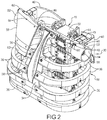
FIG. 2 is a perspective view of an omni-directional shoulder assembly, according to one embodiment of the present invention, of the crash test dummy ofFIG. 1 . -
FIG. 3 is another perspective view of the omni-directional shoulder assembly ofFIG. 2 for the crash test dummy ofFIG. 1 . -
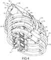
FIG. 4 is yet another perspective view of the omni-directional shoulder assembly ofFIG. 2 for the crash test dummy ofFIG. 1 . -
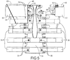
FIG. 5 is a front view of the omni-directional shoulder assembly ofFIG. 2 illustrated in operational relationship with a portion of the crash test dummy ofFIG. 1 . -
FIG. 6 is a left side view of the omni-directional shoulder assembly ofFIG. 5 . -
FIG. 7 is a rear view of the omni-directional shoulder assembly ofFIG. 5 . -
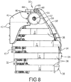
FIG. 8 is a right side view of the omni-directional shoulder assembly ofFIG. 5 . -
FIG. 9 is a top view of the omni-directional shoulder assembly ofFIG. 5 . -
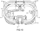
FIG. 10 is a bottom view of the omni-directional shoulder assembly ofFIG. 5 . -
FIG. 1 1 is a perspective exploded view of the omni-directional shoulder assembly ofFIG. 5 illustrating an arm assembly of the crash test dummy ofFIG. 1 . -
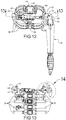
FIG. 12 is a top view of the omni-directional shoulder assembly ofFIG. 5 illustrating an arm assembly of the crash test dummy ofFIG. 1 . -
FIG. 13 is a sectional view taken along line 13 - 13 ofFIG. 12 . -
FIG. 14 is an enlarged view of a portion of the omni-directional shoulder assembly incircle 14 ofFIG. 13 . - Referring to the drawings and in particular
FIG. 1 , one embodiment of a crash test dummy, according to the present invention, is generally indicated at 12. Thecrash test dummy 12 is of a 10.5 year old child and is illustrated in a standing position. Thiscrash test dummy 12 is used primarily to test the performance of automotive interiors and restraint systems for front and rear seat occupants. The size and weight of thecrash test dummy 12 are based on anthropometric studies, which are typically done separately by the following organizations, University of Michigan Transportation Research Institute (UMTRI), U.S. Military Anthropometry Survey (ANSUR), and Civilian American and European Surface Anthropometry Resource (CESAR). It should be appreciated that ranges of motions, centers of gravity, and segment masses simulate those of human subjects defined by the anthropometric data. - As illustrated in
FIG. 1 , thecrash test dummy 12 includes a head assembly, generally indicated at 14. Thecrash test dummy 12 also includes a spine assembly, generally indicated at 15, (FIG. 2 ) having an upper end mounted to thehead assembly 14 and a lower end extending into a torso area of thecrash test dummy 12. It should be appreciated that thespine assembly 15 includes a neck (not shown) attached to thehead assembly 14. - The torso area of the
crash test dummy 12 also includes a rib cage or torso assembly, generally indicated at 16, connected to thespine assembly 15. Thecrash test dummy 12 also has a pair of arm assemblies including a right arm assembly, generally indicated at 18, and a left arm assembly, generally indicated at 20, which are attached to thecrash test dummy 12 via anomnidirectional shoulder assembly 30, according to the present invention, to be described. It should be appreciated that a lower end of thespine assembly 15 is connected to a lumbar-thoracic adapter (not shown), which is connected to a lumbar to pelvic adapter (not shown). - As illustrated in the
FIG. 1 , thecrash test dummy 12 includes a pelvis assembly, generally indicated at 22, connected to the adapter. Thecrash test dummy 12 also includes aright leg assembly 24 and aleft leg assembly 26, which are attached to thepelvis assembly 22. It should be appreciated that various components of thecrash test dummy 12 may be covered in a polyvinyl skin such as a flesh and skin assembly, generally indicated at 28 and partially shown, for biofidelity of thecrash test dummy 12. - Referring to
FIGS. 2 through 14 , one embodiment of an omni-directional shoulder assembly 30, according to the present invention, is shown for thecrash test dummy 12. Theshoulder assembly 30 can be used on both the right hand and left hand positions of thecrash test dummy 12 with different parts mirrored on a mid-sagittal plane. In the embodiment illustrated, oneshoulder assembly 30 is on the right hand position of thecrash test dummy 12 and anothershoulder assembly 30 is on the left hand position of thecrash test dummy 12. Since theshoulder assembly 30 is symmetric for each of the right hand and left hand positions of thecrash test dummy 12, only oneshoulder assembly 30 will be subsequently described. It should be appreciated that the subsequent description of theshoulder assembly 30 is the same for both the right hand and left hand positions of thecrash test dummy 12. - As illustrated, the
shoulder assembly 30 is connected to thespine assembly 15. Thespine assembly 15 includes a neck (not shown) connected to thehead assembly 14 and aspine box 32 connected to the neck. The neck has a lower end connected to by a suitable attachment such as one or more fasteners (not shown) to thespine box 32. It should be appreciated that the fasteners threadably engage apertures (not shown) in thespine box 32 to secure the neck to thespine box 32. - The
torso assembly 16 includes asternum 34 spaced forwardly from thespine box 32. Thesternum 34 is generally rectangular in shape, but may be any suitable shape. Thetorso assembly 16 also includes one ormore ribs 36 extending between thespine box 32 andsternum 34. Theribs 36 are generally arcuate in shape and generally rectangular in cross-sectional shape, but may be any suitable shape. Theribs 36 are vertically spaced along thespine box 32 andsternum 34. Theribs 36 are connected to thespine box 32 andsternum 34 by a suitable mechanism such as one ormore fasteners 38. - As illustrated in one embodiment, the
shoulder assembly 30 includes a pair ofscapulas 40 connected to thespine box 32. Thescapulas 40 are generally triangular and arcuate in shape. Thescapulas 40 are made of a plastic material such as polyurethane. Thescapulas 40 have one end mounted to one or more mountingmembers 41 of thespine box 32 by a suitable mechanism such as one ormore fasteners 42. The mountingmembers 41 are generally rectangular in shape, but may be any suitable shape. The mountingmembers 41 are made of an elastomeric material such as rubber. The mountingmembers 41 are mounted to thespine box 32 by one ormore fasteners 38. Thescapulas 40 are non-rigidly mounted to thespine box 32 via the mountingmembers 41 such that thescapulas 40 are free to move in three-dimensional space. It should be appreciated that thescapula 40 has the ability to slide freely and is not rigidly affixed to thespine box 32. It should also be appreciated that the mountingmembers 41 allow thescapulas 40 to slide over theribs 36 without contacting them. - The
shoulder assembly 30 also includes a pair of mountingbrackets 44 at one end of thescapulas 40 and connected to thescapulas 40 by a suitable mechanism such asfasteners 46. The mountingbracket 44 is made of a metal material such as steel and aluminum. Theshoulder assembly 30 also includes a pair ofclavicles 48 mounted to thesternum 34 and to one or more mountingmembers 45 of the mountingbrackets 44 by a suitable mechanism such asfasteners 50. The mountingmembers 45 are generally rectangular in shape, but may be any suitable shape. The mountingmembers 45 are made of an elastomeric material such as rubber. Theclavicles 48 are generally cylindrical in shape and extend transversely across the torso. Theclavicles 48 are non- rigidly mounted via the mountingmembers 45 to the mountingbrackets 44 such that theclavicles 48 are free to move in three-dimensional space. It should be appreciated that theclavicles 48 have a free range of motion and are not rigidly attached to thesternum 34. - In operation, an impact on the
shoulder assembly 30 of thecrash test dummy 12 would move theshoulder assembly 30 towards thespine assembly 15. Theshoulder assembly 30 is supported only by thescapula 40 andclavicle 48. The mountingmembers spine assembly 15 which, in turn, would allow thescapula 40 to slide over theribs 36 without any contact being applied to theribs 36. Although thescapula 40 andclavicle 48 are attached to thespine assembly 15 andsternum 34, the mountingmembers scapula 40 andclavicle 48 without having any or minimal movement to the remainder of thecrash test dummy 12. - The
shoulder assembly 30 also includes ashoulder cup member 52 mounted to the mountingbracket 44. Theshoulder cup member 52 is generally cylindrical in shape and extends laterally. Theshoulder cup member 52 has asocket 54 extending axially therein to form a shoulder ball joint. Thesocket 54 is generally hemi-spherical in shape. Theshoulder cup member 52 also has anaperture 55 extending from a bottom of thesocket 54 axially therethrough. Theshoulder cup member 52 is made of a metal material such as steel and aluminum. Theshoulder cup member 52 is connected to the mountingbracket 44 by a suitable mechanism such asfasteners 56. - The
shoulder assembly 30 also includes a pair ofbreastplates 58 connected to theclavicles 48. Thebreastplates 58 are generally trapezoidal in shape and extend from a relatively large widthfirst end 60 to a relatively smaller widthsecond end 62. Thefirst end 60 is generally arcuate in shape and disposed over theclavicle 48. Thebreastplates 58 are made of a plastic material. Thebreastplates 58 may be secured to theclavicle 48 andribs 36 by a suitable mechanism such asfasteners 64. - The
shoulder assembly 30 further includes anupper arm portion 66 of thearm assembly upper arm portion 66 includes ahumerous bone 68 disposed therein and extending axially. Theupper arm portion 66 is made with solid flesh (not shown) extending around thebone 68. Thebone 68 is made of a plastic material such as nylon. Theupper arm portion 66 includes aball 70 at one end of thebone 68 having a threadedfastener 72 molded inside it. Theball 70 has aninner portion 73a made of a metal material such as aluminum and may have anouter portion 73b made of an elastomeric material such as urethane molded around theinner portion 73a. Theball 70 is disposed in thesocket 54 and connected to thesocket portion 54. Theball 70 also has aslot 74 in theouter portion 73b. The threadedfastener 72 on theball 70 gets threaded into theshoulder cup 52. Afastener 76 is inserted into the opposite end of theshoulder cup 52 and into a threadedhole 78 in the end of the threadedfastener 72 which keeps the threadedfastener 72 from backing out when theupper arm portion 66 rotates. Thebone 68 has anaperture 80 extending therethrough disposed about theinner portion 73 a of theball 70 and in theslot 74 of theouter portion 73b of theball 70. It should be appreciated that theouter portion 73 a rides inside thesocket 54 on theshoulder cup 52. It should also be appreciated that the ball joint allows thearm assembly 20 to be lifted up and down and allows theentire arm assembly 20 to rotate 360 degrees inside theshoulder cup 52. It should be appreciated that thebone 68 is attached with the ball joint and the bone structures are made of plastic materials to mimic human skeletal weight and strength. - Accordingly, the omni-
directional shoulder assembly 30 of the present invention allows omni direction measurements. In addition, the omni-directional shoulder assembly 30 of the present invention meets lateral and frontal biofidelity of thecrash test dummy 12. Theomnidirectional shoulder assembly 30 also has the ability to move in three-dimensional space (i.e., all three axes) to mimic that of a human being. It should be appreciated that thecrash test dummy 12 with the omni-directional shoulder assembly 30 is a surrogate to mimic human responses in an automotive restraint system for different modes of impact during automobile crash tests.
Claims (10)
- A shoulder assembly (30) for a crash test dummy (12) comprising:a movable clavicle (48) adapted for attachment to a spine (15) of the crash test dummy (12) for freedom of movement in three-dimensional space;a scapula (40) non-rigidly adapted for attachment to the spine (15) for freedom of movement in three-dimensional space;a shoulder cup member (52) adapted for attachment to the spine (15) in a plurality of axes for a shoulder ball joint; andan upper arm assembly (66) having an arm bone (68) and having a ball (70) at one end for connection to said shoulder cup member (52), characterized inthat said shoulder cup member (52) includes a socket (54) extending axially therein to form said shoulder ball joint, said socket (54) being hemi-spherically shaped and said ball (70) being spherically shaped.that said arm bone (68) is made of a plastic material,that said shoulder cup member (52) allows an impact on the shoulder ball joint of the dummy (12) to move the shoulder assembly (30) towards the spine (15), said shoulder assembly (30) being supported only by said scapula (40) and said clavicle (48),that said ball (70) includes a slot (74) therein to allow said bone (68) to rotate; andthat a first threaded fastener (72) on said ball (70) is disposed in one end of said shoulder cup member (52) and threadingly engages said shoulder cup member (52), said first threaded fastener (72) having a threaded hole (78) and a second threaded fastener (76) extends through an opposite end of said shoulder cup member (52) and threadingly engages said threaded hole (78) of said first threaded fastener (72) to keep said threaded first fastener (72) from backing out when said upper arm assembly (66) rotates.
- A shoulder assembly as set forth in claim 1 wherein said ball (70) has an inner portion (73a) made of a metal material and an outer portion (73b) made of an elastomeric material disposed about an outer surface of said inner portion (73a).
- A shoulder assembly as set forth in claim 2 wherein said outer portion (73b) of said ball (70) includes said slot (74) therein to allow said bone (68) to rotate.
- A shoulder assembly as set forth in any one preceding claim including at least one mounting member (41) adapted to be disposed between said scapula (40) and the spine (15).
- A shoulder assembly as set forth in claim 4 wherein said at least one mounting member (41) is made of an elastomeric material.
- A shoulder assembly as set forth in any one preceding claim including at least one mounting member (45) connected to said clavicle (48).
- A shoulder assembly as set forth in any one preceding_wherein said at least one mounting member (45) is made of an elastomeric material.
- A crash test dummy (12) comprising:a body;a spine assembly (15) operatively attached to said body; anda shoulder assembly (30) according to claim 1.
- A crash test dummy as set forth in claim 8 wherein said shoulder cup portion (52) includes a socket (54) that is hemi-spherically shaped and said ball (70) is spherically shaped.
- A crash test dummy as set forth in any one of claims 8 to 9 wherein said ball (70) has an inner portion (73a) made of a metal material and an outer portion (73b) made of an elastomeric material disposed about an outer surface of said inner portion (73a)., wherein said outer portion (73b) of said ball (70) includes a slot (74) therein to allow said bone (68) to rotate, and at least one mounting member (41) disposed between said scapula (40) and said spine assembly (15).
Applications Claiming Priority (3)
| Application Number | Priority Date | Filing Date | Title |
|---|---|---|---|
| US201462051574P | 2014-09-17 | 2014-09-17 | |
| US14/855,886 US10008130B2 (en) | 2014-09-17 | 2015-09-16 | Omni-directional shoulder assembly for crash test dummy |
| PCT/US2015/050706 WO2016044601A1 (en) | 2014-09-17 | 2015-09-17 | Omni-directional shoulder assembly for crash test dummy |
Publications (2)
| Publication Number | Publication Date |
|---|---|
| EP3195295A1 EP3195295A1 (en) | 2017-07-26 |
| EP3195295B1 true EP3195295B1 (en) | 2020-05-27 |
Family
ID=55455294
Family Applications (1)
| Application Number | Title | Priority Date | Filing Date |
|---|---|---|---|
| EP15774790.8A Active EP3195295B1 (en) | 2014-09-17 | 2015-09-17 | Omni-directional shoulder assembly for crash test dummy |
Country Status (3)
| Country | Link |
|---|---|
| US (2) | US10008130B2 (en) |
| EP (1) | EP3195295B1 (en) |
| WO (1) | WO2016044601A1 (en) |
Families Citing this family (12)
| Publication number | Priority date | Publication date | Assignee | Title |
|---|---|---|---|---|
| US9970835B2 (en) | 2015-11-02 | 2018-05-15 | Humanetics Innovative Solutions, Inc. | String pot system for crash test dummy |
| CN106409104B (en) * | 2016-11-08 | 2020-04-10 | 天津天堰科技股份有限公司 | Thoracic arch spring teaching aid |
| JP6357713B1 (en) | 2016-11-30 | 2018-07-18 | 石川 輝子 | Displacement measuring device |
| GB2611200B (en) * | 2018-11-01 | 2023-11-01 | Humanetics Innovative Solutions Inc | Pad assembly for anthropomorphic test device |
| CN109559615B (en) * | 2018-12-19 | 2020-12-01 | 南方医科大学深圳医院 | Fixed structure of sports biomechanical simulation structure |
| CN111223375B (en) * | 2020-01-16 | 2021-10-29 | 京东方科技集团股份有限公司 | Grips that simulate limb movements |
| GB202004653D0 (en) * | 2020-03-30 | 2020-05-13 | Univ Loughborough | Neck assembly and uses thereof |
| CN111862756B (en) * | 2020-07-02 | 2024-10-29 | 营口巨成教学科技开发有限公司 | Simulation person for simulation chest and chest compression training |
| JP2023020951A (en) * | 2021-07-30 | 2023-02-09 | キストラー ホールディング アクチエンゲゼルシャフト | Humanoid type testing device with shoulder assembly, use of the testing device, and manufacture of shoulder assembly for humanoid type testing device |
| EP4413561A4 (en) * | 2021-10-07 | 2025-06-25 | Dynamic Research, Inc. | ARTICULATED PEDESTRIAN DUMMY FOR VEHICLE TESTING |
| CN116086823B (en) * | 2022-12-15 | 2026-04-10 | 清华大学苏州汽车研究院(相城) | Shoulder structure for vehicle collision |
| CN121207472B (en) * | 2025-11-28 | 2026-02-27 | 中国汽车技术研究中心有限公司 | Shoulder multidirectional buffering self-adaptive restraint device for side collision dummy |
Family Cites Families (23)
| Publication number | Priority date | Publication date | Assignee | Title |
|---|---|---|---|---|
| GB1232970A (en) * | 1969-08-08 | 1971-05-26 | ||
| US4261113A (en) | 1979-08-31 | 1981-04-14 | Humanetics, Inc. | Anthropomorphic dummy for use in vehicle crash testing |
| US4349339A (en) | 1981-07-31 | 1982-09-14 | Ford Motor Company | Force-indicating dummy legs |
| US5317931A (en) | 1992-05-15 | 1994-06-07 | First Technology Safety Systems, Inc. | Apparatus for sensing deflection in a crash test dummy thorax |
| US5526707A (en) | 1994-05-20 | 1996-06-18 | First Technology Safety Systems, Inc. | Fetal insert assembly for a female crash test dummy |
| US5528943A (en) | 1994-05-20 | 1996-06-25 | First Technology Safety Systems, Inc. | Female crash test dummy having fetal insert |
| US5589651A (en) | 1994-10-28 | 1996-12-31 | First Technology Safety Systems, Inc. | Lower leg for crash test dummy |
| FR2751343B1 (en) | 1996-07-16 | 1998-12-18 | Transgene Sa | PROCESS FOR THE PRESERVATION OF INFECTIOUS RECOMBINANT VIRUSES, AQUEOUS VIRAL SUSPENSION, AND USE AS A MEDICAMENT |
| JP3602829B2 (en) | 2002-02-06 | 2004-12-15 | 株式会社玉俊工業所 | Free arm connection mechanism for body mannequin |
| US6982409B2 (en) | 2002-02-21 | 2006-01-03 | First Technology Safety Systems, Inc. | Measurement system for ball joint of crash test dummy |
| US20070131043A1 (en) * | 2003-11-14 | 2007-06-14 | Frost Martha L | Ballast test dummy |
| US7086273B2 (en) | 2003-12-05 | 2006-08-08 | First Technology Safety Systems, Inc. | Flexible printed circuit cabling system for crash test dummy |
| US8407033B2 (en) | 2009-06-23 | 2013-03-26 | Humanetics Innovative Solutions, Inc. | System for modeling dynamic response changes in an anthropomorphic dummy |
| WO2012011417A1 (en) * | 2010-07-23 | 2012-01-26 | Takasu Shuhei | Human phantom training aid for mastering manipulative techniques and method for mastering manipulative techniques using human phantom training aid |
| US9422969B2 (en) * | 2010-08-12 | 2016-08-23 | Allen Forrest Jackson | Locking system |
| US8622748B2 (en) | 2010-12-30 | 2014-01-07 | Humanetics Innovative Solutions, Inc. | Ankle assembly for crash test dummy |
| US8840404B2 (en) | 2010-12-30 | 2014-09-23 | Humanetics Innovative Solutions, Inc. | Rib cage assembly for crash test dummy |
| US9043187B2 (en) | 2010-12-30 | 2015-05-26 | Humanetics Innovative Solutions, Inc. | Method of material modeling for crash test dummy finite element models |
| JP5594900B2 (en) | 2011-02-14 | 2014-09-24 | 株式会社ジャスティ | Human body dummy joint |
| US9355575B2 (en) | 2012-06-12 | 2016-05-31 | Humanetics Innovative Solutions, Inc. | Chest band assembly for crash test dummy |
| US9514659B2 (en) | 2013-01-07 | 2016-12-06 | Humanetics Innovative Solutions, Inc. | Upper arm assembly for crash test dummy |
| US9916775B2 (en) * | 2013-03-27 | 2018-03-13 | Humanetics Innovative Solutions, Inc. | Joint assembly for crash test dummy |
| US9754514B2 (en) | 2013-09-25 | 2017-09-05 | Humanetics Innovative Solutions, Inc. | Adjustable friction joint assembly for crash test dummy |
-
2015
- 2015-09-16 US US14/855,886 patent/US10008130B2/en active Active
- 2015-09-17 EP EP15774790.8A patent/EP3195295B1/en active Active
- 2015-09-17 WO PCT/US2015/050706 patent/WO2016044601A1/en not_active Ceased
-
2018
- 2018-06-11 US US16/005,362 patent/US10262557B2/en active Active
Non-Patent Citations (1)
| Title |
|---|
| None * |
Also Published As
| Publication number | Publication date |
|---|---|
| US10262557B2 (en) | 2019-04-16 |
| US20180293914A1 (en) | 2018-10-11 |
| EP3195295A1 (en) | 2017-07-26 |
| US10008130B2 (en) | 2018-06-26 |
| US20160078783A1 (en) | 2016-03-17 |
| WO2016044601A1 (en) | 2016-03-24 |
Similar Documents
| Publication | Publication Date | Title |
|---|---|---|
| US10262557B2 (en) | Omni-directional shoulder assembly for crash test dummy | |
| US9514659B2 (en) | Upper arm assembly for crash test dummy | |
| US9564069B2 (en) | Flexible surrogate spine assembly for crash test dummy | |
| US9916775B2 (en) | Joint assembly for crash test dummy | |
| US9972220B2 (en) | Omnidirectional neck assembly for crash test dummy | |
| US9947244B2 (en) | Adjustable spine joint assembly for crash test dummy | |
| US8840404B2 (en) | Rib cage assembly for crash test dummy | |
| US9965977B2 (en) | Adjustable lumbar spine assembly for crash test dummy | |
| US9754514B2 (en) | Adjustable friction joint assembly for crash test dummy | |
| US20190371207A1 (en) | Internal organ assembly for crash test dummy | |
| US10585019B2 (en) | Neck assembly for anthropomorphic test device | |
| US9721484B2 (en) | Shoulder kit assembly for crash test dummy | |
| US11200816B2 (en) | Head assembly with facial insert for crash test dummy | |
| US20240355232A1 (en) | Spine Adjustment Joint With Angle Adjustment For Crash Test Dummy | |
| EP3392638A1 (en) | Neck assembly for anthropomorphic test device | |
| US20170278430A1 (en) | Ribs for crash test dummy |
Legal Events
| Date | Code | Title | Description |
|---|---|---|---|
| STAA | Information on the status of an ep patent application or granted ep patent |
Free format text: STATUS: THE INTERNATIONAL PUBLICATION HAS BEEN MADE |
|
| PUAI | Public reference made under article 153(3) epc to a published international application that has entered the european phase |
Free format text: ORIGINAL CODE: 0009012 |
|
| STAA | Information on the status of an ep patent application or granted ep patent |
Free format text: STATUS: REQUEST FOR EXAMINATION WAS MADE |
|
| 17P | Request for examination filed |
Effective date: 20170306 |
|
| AK | Designated contracting states |
Kind code of ref document: A1 Designated state(s): AL AT BE BG CH CY CZ DE DK EE ES FI FR GB GR HR HU IE IS IT LI LT LU LV MC MK MT NL NO PL PT RO RS SE SI SK SM TR |
|
| AX | Request for extension of the european patent |
Extension state: BA ME |
|
| DAV | Request for validation of the european patent (deleted) | ||
| DAX | Request for extension of the european patent (deleted) | ||
| STAA | Information on the status of an ep patent application or granted ep patent |
Free format text: STATUS: EXAMINATION IS IN PROGRESS |
|
| 17Q | First examination report despatched |
Effective date: 20190507 |
|
| GRAP | Despatch of communication of intention to grant a patent |
Free format text: ORIGINAL CODE: EPIDOSNIGR1 |
|
| STAA | Information on the status of an ep patent application or granted ep patent |
Free format text: STATUS: GRANT OF PATENT IS INTENDED |
|
| INTG | Intention to grant announced |
Effective date: 20200122 |
|
| GRAS | Grant fee paid |
Free format text: ORIGINAL CODE: EPIDOSNIGR3 |
|
| GRAA | (expected) grant |
Free format text: ORIGINAL CODE: 0009210 |
|
| STAA | Information on the status of an ep patent application or granted ep patent |
Free format text: STATUS: THE PATENT HAS BEEN GRANTED |
|
| AK | Designated contracting states |
Kind code of ref document: B1 Designated state(s): AL AT BE BG CH CY CZ DE DK EE ES FI FR GB GR HR HU IE IS IT LI LT LU LV MC MK MT NL NO PL PT RO RS SE SI SK SM TR |
|
| REG | Reference to a national code |
Ref country code: GB Ref legal event code: FG4D |
|
| REG | Reference to a national code |
Ref country code: CH Ref legal event code: EP |
|
| REG | Reference to a national code |
Ref country code: DE Ref legal event code: R096 Ref document number: 602015053410 Country of ref document: DE |
|
| REG | Reference to a national code |
Ref country code: AT Ref legal event code: REF Ref document number: 1275361 Country of ref document: AT Kind code of ref document: T Effective date: 20200615 |
|
| REG | Reference to a national code |
Ref country code: LT Ref legal event code: MG4D |
|
| PG25 | Lapsed in a contracting state [announced via postgrant information from national office to epo] |
Ref country code: NO Free format text: LAPSE BECAUSE OF FAILURE TO SUBMIT A TRANSLATION OF THE DESCRIPTION OR TO PAY THE FEE WITHIN THE PRESCRIBED TIME-LIMIT Effective date: 20200827 Ref country code: PT Free format text: LAPSE BECAUSE OF FAILURE TO SUBMIT A TRANSLATION OF THE DESCRIPTION OR TO PAY THE FEE WITHIN THE PRESCRIBED TIME-LIMIT Effective date: 20200928 Ref country code: FI Free format text: LAPSE BECAUSE OF FAILURE TO SUBMIT A TRANSLATION OF THE DESCRIPTION OR TO PAY THE FEE WITHIN THE PRESCRIBED TIME-LIMIT Effective date: 20200527 Ref country code: LT Free format text: LAPSE BECAUSE OF FAILURE TO SUBMIT A TRANSLATION OF THE DESCRIPTION OR TO PAY THE FEE WITHIN THE PRESCRIBED TIME-LIMIT Effective date: 20200527 Ref country code: SE Free format text: LAPSE BECAUSE OF FAILURE TO SUBMIT A TRANSLATION OF THE DESCRIPTION OR TO PAY THE FEE WITHIN THE PRESCRIBED TIME-LIMIT Effective date: 20200527 Ref country code: IS Free format text: LAPSE BECAUSE OF FAILURE TO SUBMIT A TRANSLATION OF THE DESCRIPTION OR TO PAY THE FEE WITHIN THE PRESCRIBED TIME-LIMIT Effective date: 20200927 Ref country code: GR Free format text: LAPSE BECAUSE OF FAILURE TO SUBMIT A TRANSLATION OF THE DESCRIPTION OR TO PAY THE FEE WITHIN THE PRESCRIBED TIME-LIMIT Effective date: 20200828 |
|
| REG | Reference to a national code |
Ref country code: NL Ref legal event code: MP Effective date: 20200527 |
|
| PG25 | Lapsed in a contracting state [announced via postgrant information from national office to epo] |
Ref country code: BG Free format text: LAPSE BECAUSE OF FAILURE TO SUBMIT A TRANSLATION OF THE DESCRIPTION OR TO PAY THE FEE WITHIN THE PRESCRIBED TIME-LIMIT Effective date: 20200827 Ref country code: RS Free format text: LAPSE BECAUSE OF FAILURE TO SUBMIT A TRANSLATION OF THE DESCRIPTION OR TO PAY THE FEE WITHIN THE PRESCRIBED TIME-LIMIT Effective date: 20200527 Ref country code: LV Free format text: LAPSE BECAUSE OF FAILURE TO SUBMIT A TRANSLATION OF THE DESCRIPTION OR TO PAY THE FEE WITHIN THE PRESCRIBED TIME-LIMIT Effective date: 20200527 Ref country code: HR Free format text: LAPSE BECAUSE OF FAILURE TO SUBMIT A TRANSLATION OF THE DESCRIPTION OR TO PAY THE FEE WITHIN THE PRESCRIBED TIME-LIMIT Effective date: 20200527 |
|
| REG | Reference to a national code |
Ref country code: AT Ref legal event code: MK05 Ref document number: 1275361 Country of ref document: AT Kind code of ref document: T Effective date: 20200527 |
|
| PG25 | Lapsed in a contracting state [announced via postgrant information from national office to epo] |
Ref country code: AL Free format text: LAPSE BECAUSE OF FAILURE TO SUBMIT A TRANSLATION OF THE DESCRIPTION OR TO PAY THE FEE WITHIN THE PRESCRIBED TIME-LIMIT Effective date: 20200527 Ref country code: NL Free format text: LAPSE BECAUSE OF FAILURE TO SUBMIT A TRANSLATION OF THE DESCRIPTION OR TO PAY THE FEE WITHIN THE PRESCRIBED TIME-LIMIT Effective date: 20200527 |
|
| PG25 | Lapsed in a contracting state [announced via postgrant information from national office to epo] |
Ref country code: ES Free format text: LAPSE BECAUSE OF FAILURE TO SUBMIT A TRANSLATION OF THE DESCRIPTION OR TO PAY THE FEE WITHIN THE PRESCRIBED TIME-LIMIT Effective date: 20200527 Ref country code: DK Free format text: LAPSE BECAUSE OF FAILURE TO SUBMIT A TRANSLATION OF THE DESCRIPTION OR TO PAY THE FEE WITHIN THE PRESCRIBED TIME-LIMIT Effective date: 20200527 Ref country code: CZ Free format text: LAPSE BECAUSE OF FAILURE TO SUBMIT A TRANSLATION OF THE DESCRIPTION OR TO PAY THE FEE WITHIN THE PRESCRIBED TIME-LIMIT Effective date: 20200527 Ref country code: SM Free format text: LAPSE BECAUSE OF FAILURE TO SUBMIT A TRANSLATION OF THE DESCRIPTION OR TO PAY THE FEE WITHIN THE PRESCRIBED TIME-LIMIT Effective date: 20200527 Ref country code: EE Free format text: LAPSE BECAUSE OF FAILURE TO SUBMIT A TRANSLATION OF THE DESCRIPTION OR TO PAY THE FEE WITHIN THE PRESCRIBED TIME-LIMIT Effective date: 20200527 Ref country code: AT Free format text: LAPSE BECAUSE OF FAILURE TO SUBMIT A TRANSLATION OF THE DESCRIPTION OR TO PAY THE FEE WITHIN THE PRESCRIBED TIME-LIMIT Effective date: 20200527 Ref country code: RO Free format text: LAPSE BECAUSE OF FAILURE TO SUBMIT A TRANSLATION OF THE DESCRIPTION OR TO PAY THE FEE WITHIN THE PRESCRIBED TIME-LIMIT Effective date: 20200527 Ref country code: IT Free format text: LAPSE BECAUSE OF FAILURE TO SUBMIT A TRANSLATION OF THE DESCRIPTION OR TO PAY THE FEE WITHIN THE PRESCRIBED TIME-LIMIT Effective date: 20200527 |
|
| PG25 | Lapsed in a contracting state [announced via postgrant information from national office to epo] |
Ref country code: SK Free format text: LAPSE BECAUSE OF FAILURE TO SUBMIT A TRANSLATION OF THE DESCRIPTION OR TO PAY THE FEE WITHIN THE PRESCRIBED TIME-LIMIT Effective date: 20200527 Ref country code: PL Free format text: LAPSE BECAUSE OF FAILURE TO SUBMIT A TRANSLATION OF THE DESCRIPTION OR TO PAY THE FEE WITHIN THE PRESCRIBED TIME-LIMIT Effective date: 20200527 |
|
| REG | Reference to a national code |
Ref country code: DE Ref legal event code: R097 Ref document number: 602015053410 Country of ref document: DE |
|
| PLBE | No opposition filed within time limit |
Free format text: ORIGINAL CODE: 0009261 |
|
| STAA | Information on the status of an ep patent application or granted ep patent |
Free format text: STATUS: NO OPPOSITION FILED WITHIN TIME LIMIT |
|
| PG25 | Lapsed in a contracting state [announced via postgrant information from national office to epo] |
Ref country code: MC Free format text: LAPSE BECAUSE OF FAILURE TO SUBMIT A TRANSLATION OF THE DESCRIPTION OR TO PAY THE FEE WITHIN THE PRESCRIBED TIME-LIMIT Effective date: 20200527 |
|
| REG | Reference to a national code |
Ref country code: CH Ref legal event code: PL |
|
| 26N | No opposition filed |
Effective date: 20210302 |
|
| PG25 | Lapsed in a contracting state [announced via postgrant information from national office to epo] |
Ref country code: SI Free format text: LAPSE BECAUSE OF FAILURE TO SUBMIT A TRANSLATION OF THE DESCRIPTION OR TO PAY THE FEE WITHIN THE PRESCRIBED TIME-LIMIT Effective date: 20200527 |
|
| REG | Reference to a national code |
Ref country code: BE Ref legal event code: MM Effective date: 20200930 |
|
| PG25 | Lapsed in a contracting state [announced via postgrant information from national office to epo] |
Ref country code: LU Free format text: LAPSE BECAUSE OF NON-PAYMENT OF DUE FEES Effective date: 20200917 |
|
| PG25 | Lapsed in a contracting state [announced via postgrant information from national office to epo] |
Ref country code: FR Free format text: LAPSE BECAUSE OF NON-PAYMENT OF DUE FEES Effective date: 20200930 |
|
| PG25 | Lapsed in a contracting state [announced via postgrant information from national office to epo] |
Ref country code: BE Free format text: LAPSE BECAUSE OF NON-PAYMENT OF DUE FEES Effective date: 20200930 Ref country code: CH Free format text: LAPSE BECAUSE OF NON-PAYMENT OF DUE FEES Effective date: 20200930 Ref country code: LI Free format text: LAPSE BECAUSE OF NON-PAYMENT OF DUE FEES Effective date: 20200930 Ref country code: IE Free format text: LAPSE BECAUSE OF NON-PAYMENT OF DUE FEES Effective date: 20200917 |
|
| PG25 | Lapsed in a contracting state [announced via postgrant information from national office to epo] |
Ref country code: TR Free format text: LAPSE BECAUSE OF FAILURE TO SUBMIT A TRANSLATION OF THE DESCRIPTION OR TO PAY THE FEE WITHIN THE PRESCRIBED TIME-LIMIT Effective date: 20200527 Ref country code: MT Free format text: LAPSE BECAUSE OF FAILURE TO SUBMIT A TRANSLATION OF THE DESCRIPTION OR TO PAY THE FEE WITHIN THE PRESCRIBED TIME-LIMIT Effective date: 20200527 Ref country code: CY Free format text: LAPSE BECAUSE OF FAILURE TO SUBMIT A TRANSLATION OF THE DESCRIPTION OR TO PAY THE FEE WITHIN THE PRESCRIBED TIME-LIMIT Effective date: 20200527 |
|
| PG25 | Lapsed in a contracting state [announced via postgrant information from national office to epo] |
Ref country code: MK Free format text: LAPSE BECAUSE OF FAILURE TO SUBMIT A TRANSLATION OF THE DESCRIPTION OR TO PAY THE FEE WITHIN THE PRESCRIBED TIME-LIMIT Effective date: 20200527 |
|
| P01 | Opt-out of the competence of the unified patent court (upc) registered |
Effective date: 20230524 |
|
| PGFP | Annual fee paid to national office [announced via postgrant information from national office to epo] |
Ref country code: DE Payment date: 20240927 Year of fee payment: 10 |
|
| PGFP | Annual fee paid to national office [announced via postgrant information from national office to epo] |
Ref country code: GB Payment date: 20240927 Year of fee payment: 10 |