EP3195108B1 - System and method for integrating an authentication service within a network architecture - Google Patents
System and method for integrating an authentication service within a network architecture Download PDFInfo
- Publication number
- EP3195108B1 EP3195108B1 EP15841530.7A EP15841530A EP3195108B1 EP 3195108 B1 EP3195108 B1 EP 3195108B1 EP 15841530 A EP15841530 A EP 15841530A EP 3195108 B1 EP3195108 B1 EP 3195108B1
- Authority
- EP
- European Patent Office
- Prior art keywords
- authentication
- gateway
- authentication server
- user
- client
- Prior art date
- Legal status (The legal status is an assumption and is not a legal conclusion. Google has not performed a legal analysis and makes no representation as to the accuracy of the status listed.)
- Active
Links
- 238000000034 method Methods 0.000 title claims description 44
- 230000004044 response Effects 0.000 claims description 28
- 238000004891 communication Methods 0.000 claims description 17
- 230000008878 coupling Effects 0.000 claims 1
- 238000010168 coupling process Methods 0.000 claims 1
- 238000005859 coupling reaction Methods 0.000 claims 1
- 238000012545 processing Methods 0.000 description 20
- 238000013459 approach Methods 0.000 description 12
- 230000010354 integration Effects 0.000 description 11
- 238000010200 validation analysis Methods 0.000 description 9
- 230000003287 optical effect Effects 0.000 description 6
- 238000010586 diagram Methods 0.000 description 5
- 230000008569 process Effects 0.000 description 4
- 238000012795 verification Methods 0.000 description 4
- 230000003190 augmentative effect Effects 0.000 description 3
- 230000001815 facial effect Effects 0.000 description 3
- 230000007246 mechanism Effects 0.000 description 3
- 230000006872 improvement Effects 0.000 description 2
- 230000000977 initiatory effect Effects 0.000 description 2
- 230000008520 organization Effects 0.000 description 2
- 230000009467 reduction Effects 0.000 description 2
- 210000001525 retina Anatomy 0.000 description 2
- 230000003068 static effect Effects 0.000 description 2
- 230000004888 barrier function Effects 0.000 description 1
- 230000008901 benefit Effects 0.000 description 1
- 230000001413 cellular effect Effects 0.000 description 1
- 230000008859 change Effects 0.000 description 1
- 239000002131 composite material Substances 0.000 description 1
- 230000001010 compromised effect Effects 0.000 description 1
- 230000004424 eye movement Effects 0.000 description 1
- 230000006870 function Effects 0.000 description 1
- 229910000078 germane Inorganic materials 0.000 description 1
- 230000003993 interaction Effects 0.000 description 1
- 230000004048 modification Effects 0.000 description 1
- 238000012986 modification Methods 0.000 description 1
- 230000002093 peripheral effect Effects 0.000 description 1
- 230000001105 regulatory effect Effects 0.000 description 1
- 230000000717 retained effect Effects 0.000 description 1
- 230000002207 retinal effect Effects 0.000 description 1
- 238000000926 separation method Methods 0.000 description 1
- 230000011664 signaling Effects 0.000 description 1
- 230000001960 triggered effect Effects 0.000 description 1
Images


Classifications
-
- H—ELECTRICITY
- H04—ELECTRIC COMMUNICATION TECHNIQUE
- H04L—TRANSMISSION OF DIGITAL INFORMATION, e.g. TELEGRAPHIC COMMUNICATION
- H04L63/00—Network architectures or network communication protocols for network security
- H04L63/08—Network architectures or network communication protocols for network security for authentication of entities
- H04L63/0884—Network architectures or network communication protocols for network security for authentication of entities by delegation of authentication, e.g. a proxy authenticates an entity to be authenticated on behalf of this entity vis-à-vis an authentication entity
-
- H—ELECTRICITY
- H04—ELECTRIC COMMUNICATION TECHNIQUE
- H04L—TRANSMISSION OF DIGITAL INFORMATION, e.g. TELEGRAPHIC COMMUNICATION
- H04L63/00—Network architectures or network communication protocols for network security
- H04L63/02—Network architectures or network communication protocols for network security for separating internal from external traffic, e.g. firewalls
- H04L63/0272—Virtual private networks
-
- H—ELECTRICITY
- H04—ELECTRIC COMMUNICATION TECHNIQUE
- H04L—TRANSMISSION OF DIGITAL INFORMATION, e.g. TELEGRAPHIC COMMUNICATION
- H04L63/00—Network architectures or network communication protocols for network security
- H04L63/02—Network architectures or network communication protocols for network security for separating internal from external traffic, e.g. firewalls
- H04L63/0281—Proxies
-
- H—ELECTRICITY
- H04—ELECTRIC COMMUNICATION TECHNIQUE
- H04L—TRANSMISSION OF DIGITAL INFORMATION, e.g. TELEGRAPHIC COMMUNICATION
- H04L63/00—Network architectures or network communication protocols for network security
- H04L63/08—Network architectures or network communication protocols for network security for authentication of entities
- H04L63/0807—Network architectures or network communication protocols for network security for authentication of entities using tickets, e.g. Kerberos
-
- H—ELECTRICITY
- H04—ELECTRIC COMMUNICATION TECHNIQUE
- H04L—TRANSMISSION OF DIGITAL INFORMATION, e.g. TELEGRAPHIC COMMUNICATION
- H04L63/00—Network architectures or network communication protocols for network security
- H04L63/08—Network architectures or network communication protocols for network security for authentication of entities
- H04L63/0823—Network architectures or network communication protocols for network security for authentication of entities using certificates
-
- H—ELECTRICITY
- H04—ELECTRIC COMMUNICATION TECHNIQUE
- H04L—TRANSMISSION OF DIGITAL INFORMATION, e.g. TELEGRAPHIC COMMUNICATION
- H04L63/00—Network architectures or network communication protocols for network security
- H04L63/08—Network architectures or network communication protocols for network security for authentication of entities
- H04L63/083—Network architectures or network communication protocols for network security for authentication of entities using passwords
- H04L63/0838—Network architectures or network communication protocols for network security for authentication of entities using passwords using one-time-passwords
-
- H—ELECTRICITY
- H04—ELECTRIC COMMUNICATION TECHNIQUE
- H04L—TRANSMISSION OF DIGITAL INFORMATION, e.g. TELEGRAPHIC COMMUNICATION
- H04L63/00—Network architectures or network communication protocols for network security
- H04L63/10—Network architectures or network communication protocols for network security for controlling access to devices or network resources
-
- H—ELECTRICITY
- H04—ELECTRIC COMMUNICATION TECHNIQUE
- H04L—TRANSMISSION OF DIGITAL INFORMATION, e.g. TELEGRAPHIC COMMUNICATION
- H04L63/00—Network architectures or network communication protocols for network security
- H04L63/16—Implementing security features at a particular protocol layer
- H04L63/166—Implementing security features at a particular protocol layer at the transport layer
Definitions
- This invention relates generally to the field of data processing systems. More particularly, the invention relates to a system and method for integrating an authentication service within a network architecture.
- Patent Application No. 2011/0082801 (“'801 Application”) describes a framework for user registration and authentication on a network which provides strong authentication (e.g., protection against identity theft and phishing), secure transactions (e.g., protection against "malware in the browser” and “man in the middle” attacks for transactions), and enrollment/management of client authentication tokens (e.g., fingerprint readers, facial recognition devices, smartcards, trusted platform modules, etc).
- the Co-Pending applications describe authentication techniques in which a user enrolls with authentication devices (or Authenticators) such as biometric devices (e.g., fingerprint sensors) on a client device.
- authentication devices or Authenticators
- biometric devices e.g., fingerprint sensors
- biometric reference data is captured (e.g., by swiping a finger, snapping a picture, recording a voice, etc).
- the user may subsequently register/provision the authentication devices with one or more servers over a network (e.g., Websites or other relying parties equipped with secure transaction/authentication services as described in the Co-Pending Applications); and subsequently authenticate with those servers using data exchanged during the registration process (e.g., cryptographic keys provisioned into the authentication devices).
- the user is permitted to perform one or more online transactions with a Website or other relying party.
- sensitive information such as fingerprint data and other data which can be used to uniquely identify the user, may be retained locally on the user's authentication device to protect a user's privacy.
- the '504 Application describes a variety of additional techniques including techniques for designing composite authenticators, intelligently generating authentication assurance levels, using non-intrusive user verification, transferring authentication data to new authentication devices, augmenting authentication data with client risk data, and adaptively applying authentication policies, and creating trust circles, to name just a few.
- Augmenting a Relying Party's web-based or other network enabled application to leverage the remote authentication techniques described in the co-pending applications typically requires the application to integrate directly with an authentication server. This poses a barrier to the adoption of such authentication, as Relying Parties will need to expend effort to update their applications to integrate with an authentication server in order to gain the authentication flexibility provided by the techniques described in the co-pending applications.
- the Relying Party may have already integrated with federation solutions, and thus a simple integration path is to simply integrate online authentication support into the federation solution.
- this approach does not address other legacy systems (such as VPNs, Windows Kerberos deployments) that either lack awareness of federation protocols (and thus could be front-ended by a federation server augmented with online authentication functionality), or lack sufficient extensibility to enable direct integration of online authentication functionality.
- legacy systems such as VPNs, Windows Kerberos deployments
- a key problem that must be solved for certain Relying Party applications is finding a way to enable them to integrate online authentication systems, without requiring the code for the applications themselves to be modified.
- Prior art document US 8 584 224 B1 discloses a system for authenticating a user to a relying party.
- a user sends an access request to a relying party web application.
- the application sends a page with JavaScript that detects a plug-in at the user and detects the relying party domain.
- the plug-in uses its device certificate or other pre-established credentials to sign a challenge along with other site and user information including the site domain, the authentication service URL and user identifier, and send it, along with the data including the domain and the user identifier, to an authentication service.
- the service authenticates the information and sends back to the plug-in a short ticket that can be passed on to the relying party, which can validate it using the Radius protocol and an authentication service call, thereby authenticating the user.
- Prior art document US 2014/189828 A1 discloses a system, apparatus, method, and machine readable for transparently requesting a new random challenge from a server within an authentication framework.
- a method comprises: transmitting a random challenge and an indication of a timeout period associated with the random challenge from a server to a client within the context of a network registration or authentication process using authentication devices communicatively coupled to the client; automatically detecting that the random challenge is no longer valid based on the timeout period; and responsively transmitting a request for a new random challenge from the client to a server, wherein transmitting is performed transparently to a user of the client.
- the embodiments of the invention discussed below involve authentication devices with user verification capabilities such as biometric modalities or PIN entry. These devices are sometimes referred to herein as “tokens,” “authentication devices,” or “authenticators.” While certain embodiments focus on facial recognition hardware/software (e.g., a camera and associated software for recognizing a user's face and tracking a user's eye movement), some embodiments may utilize additional biometric devices including, for example, fingerprint sensors, voice recognition hardware/software (e.g., a microphone and associated software for recognizing a user's voice), and optical recognition capabilities (e.g., an optical scanner and associated software for scanning the retina of a user).
- the user verification capabilities may also include non-biometric modalities, like PIN entry.
- the authenticators might use devices like trusted platform modules (TPMs), smartcards and secure elements for cryptographic operations and key storage.
- TPMs trusted platform modules
- the biometric device may be remote from the relying party.
- the term "remote" means that the biometric sensor is not part of the security boundary of the computer it is communicatively coupled to (e.g., it is not embedded into the same physical enclosure as the relying party computer).
- the biometric device may be coupled to the relying party via a network (e.g., the Internet, a wireless network link, etc) or via a peripheral input such as a USB port.
- the relying party may know if the device is one which is authorized by the relying party (e.g., one which provides an acceptable level of authentication strength and integrity protection) and/or whether a hacker has compromised or even replaced the biometric device. Confidence in the biometric device depends on the particular implementation of the device.
- the term "local” is used herein to refer to the fact that the user is completing a transaction in person, at a particular location such as at an automatic teller machine (ATM) or a point of sale (POS) retail checkout location.
- ATM automatic teller machine
- POS point of sale
- the authentication techniques employed to authenticate the user may involve non-location components such as communication over a network with remote servers and/or other data processing devices.
- specific embodiments are described herein (such as an ATM and retail location) it should be noted that the underlying principles of the invention may be implemented within the context of any system in which a transaction is initiated locally by an end user.
- relying party is sometimes used herein to refer, not merely to the entity with which a user transaction is attempted (e.g., a Website or online service performing user transactions), but also to the secure transaction servers (sometimes referred to as "au implemented on behalf of that entity which may performed the underlying authentication techniques described herein.
- the secure transaction servers may be owned and/or under the control of the relying party or may be under the control of a third party offering secure transaction services to the relying party as part of a business arrangement.
- server is used herein to refer to software executed on a hardware platform (or across multiple hardware platforms) that receives requests over a network from a client, responsively performs one or more operations, and transmits a response to the client, typically including the results of the operations.
- the server responds to client requests to provide, or help to provide, a network "service" to the clients.
- a server is not limited to a single computer (e.g., a single hardware device for executing the server software) and may, in fact, be spread across multiple hardware platforms, potentially at multiple geographical locations.
- Figures 1A-B illustrate two embodiments of a system architecture comprising client-side and server-side components for registering authentication devices (also sometimes referred to as "provisioning") and authenticating a user.
- the embodiment shown in Figure 1A uses a web browser plugin-based architecture for communicating with a website while the embodiment shown in Figure 1B does not require a web browser.
- the various techniques described herein such as enrolling a user with authentication devices, registering the authentication devices with a secure server, and verifying a user may be implemented on either of these system architectures.
- the illustrated embodiment includes a client 100 equipped with one or more authentication devices 110-112 (sometimes referred to in the art as authentication “tokens” or “Authenticators”) for enrolling and verifying an end user.
- the authentication devices 110-112 may include biometric device such as fingerprint sensors, voice recognition hardware/software (e.g., a microphone and associated software for recognizing a user's voice), facial recognition hardware/software (e.g., a camera and associated software for recognizing a user's face), and optical recognition capabilities (e.g., an optical scanner and associated software for scanning the retina of a user) and support for non-biometric modalities, such as PIN verification.
- the authentication devices might use trusted platform modules (TPMs), smartcards or secure elements for cryptographic operations and key storage.
- TPMs trusted platform modules
- the authentication devices 110-112 are communicatively coupled to the client through an interface 102 (e.g., an application programming interface or API) exposed by a secure transaction service 101.
- the secure transaction service 101 is a secure application for communicating with one or more secure transaction servers 132-133 over a network and for interfacing with a secure transaction plugin 105 executed within the context of a web browser 104.
- the Interface 102 may also provide secure access to a secure storage device 120 on the client 100 which stores information related to each of the authentication devices 110-112 such as a device identification code, user identification code, user enrollment data (e.g., scanned fingerprint or other biometric data) protected by he authentication device, and keys wrapped by the authentication device used to perform the secure authentication techniques described herein. For example, as discussed in detail below, a unique key may be stored into each of the authentication devices and used when communicating to servers 130 over a network such as the Internet.
- the secure transaction plugin 105 is initiated in response to specific HTML tags inserted into the HTML code of a web page by the web server 131 within the secure enterprise or Web destination 130 (sometimes simply referred to below as "server 130"). In response to detecting such a tag, the secure transaction plugin 105 may forward transactions to the secure transaction service 101 for processing. In addition, for certain types of transactions (e.g., such as secure key exchange) the secure transaction service 101 may open a direct communication channel with the on-premises transaction server 132 (i.e., co-located with the website) or with an off-premises transaction server 133.
- the on-premises transaction server 132 i.e., co-located with the website
- an off-premises transaction server 133 i.e., co-located with the website
- the secure transaction servers 132-133 are coupled to a secure transaction database 120 for storing user data, authentication device data, keys and other secure information needed to support the secure authentication transactions described below. It should be noted, however, that the underlying principles of the invention do not require the separation of logical components within the secure enterprise or web destination 130 shown in Figure 1A .
- the website 131 and the secure transaction servers 132-133 may be implemented within a single physical server or separate physical servers.
- the website 131 and transaction servers 132-133 may be implemented within an integrated software module executed on one or more servers for performing the functions described below.
- Figure 1B illustrates an alternate implementation in which a stand-alone application 154 utilizes the functionality provided by the secure transaction service 101 to authenticate a user over a network.
- the application 154 is designed to establish communication sessions with one or more network services 151 which rely on the secure transaction servers 132-133 for performing the user/client authentication techniques described in detail below.
- the secure transaction servers 132-133 may generate the keys which are then securely transmitted to the secure transaction service 101 and stored into the authentication devices within the secure storage 120. Additionally, the secure transaction servers 132-133 manage the secure transaction database 120 on the server side.
- FIG 2 illustrates a series of transactions for registering authentication devices on a client (such as devices 110-112 on client 100 in Figures 1A-B ) (sometimes referred to as “provisioning" authentication devices).
- a client such as devices 110-112 on client 100 in Figures 1A-B
- provisioning authentication devices
- the secure transaction service 101 and interface 102 are combined together as authentication client 201 and the secure enterprise or web destination 130 including the secure transaction servers 132-133 are represented as a relying party 202.
- a key associated with the authenticator is shared between the authentication client 201 and the relying party 202.
- the key may be stored within the secure storage 120 of the client 100 and the secure transaction database 120 used by the secure transaction servers 132-133.
- the key is a symmetric key generated by one of the secure transaction servers 132-133.
- asymmetric keys are be used.
- the public/private key pair may be generated by the secure transaction servers 132-133.
- the public key may then be stored by the secure transaction servers 132-133 and the related private key may be stored in the secure storage 120 on the client.
- the key(s) may be generated on the client 100 (e.g., by the authentication device or the authentication device interface rather than the secure transaction servers 132-133).
- the underlying principles of the invention are not limited to any particular types of keys or manner of generating the keys.
- a secure key provisioning protocol is employed in one embodiment to share the key with the client over a secure communication channel.
- a key provisioning protocol is the Dynamic Symmetric Key Provisioning Protocol (DSKPP) (see, e.g., Request for Comments (RFC) 6063).
- DSKPP Dynamic Symmetric Key Provisioning Protocol
- RRC Request for Comments
- the client generates a public/private key pair and sends the public key to the server, which may be attested with an attestation key.
- the relying party 202 to initiate the registration process, the relying party 202 generates a randomly generated challenge (e.g., a cryptographic nonce) that must be presented by the authentication client 201 during device registration.
- the random challenge may be valid for a limited period of time.
- the authentication client 201 initiates an out-of-band secure connection with the relying party 202 (e.g., an out-of-band transaction) and communicates with the relying party 202 using the key provisioning protocol (e.g., the DSKPP protocol mentioned above).
- the authentication client 201 may provide the random challenge back to the relying party 202 (potentially with a signature generated over the random challenge).
- the authentication client 201 may transmit the identity of the user (e.g., a user ID or other code) and the identity of the authentication device(s) to be provisioned registered (e.g., using the authentication attestation ID (AAID) which uniquely identify the type of authentication device(s) being provisioned).
- AAID authentication attestation ID
- the relying party locates the user with the user name or ID code (e.g., in a user account database), validates the random challenge (e.g., using the signature or simply comparing the random challenge to the one that was sent), validates the authentication device's authentication code if one was sent (e.g., the AAID), and creates a new entry in a secure transaction database (e.g., database 120 in Figures 1A-B ) for the user and the authentication device(s).
- the relying party maintains a database of authentication devices which it accepts for authentication. It may query this database with the AAID (or other authentication device(s) code) to determine if the authentication device(s) being provisioned are acceptable for authentication. If so, then it will proceed with the registration process.
- the relying party 202 generates an authentication key for each authentication device being provisioned. It writes the key to the secure database and sends the key back to the authentication client 201 using the key provisioning protocol. Once complete, the authentication device and the relying party 202 share the same key if a symmetric key was used or different keys if asymmetric keys were used. For example, if asymmetric keys were used, then the relying party 202 may store the public key and provide the private key to the authentication client 201. Upon receipt of the private key from the relying party 202, the authentication client 201 provisions the key into the authentication device (storing it within secure storage associated with the authentication device). It may then use the key during authentication of the user (as described below).
- the key(s) are generated by the authentication client 201 and the key provisioning protocol is used to provide the key(s) to the relying party 202. In either case, once provisioning is complete, the authentication client 201 and relying party 202 each have a key and the authentication client 201 notifies the relying party of the completion.
- Figure 3 illustrates a series of transactions for user authentication with the provisioned authentication devices.
- the relying party 202 will accept an authentication response (sometimes referred to as a "token") generated by the local authentication device on the client as a valid authentication response.
- an authentication response sometimes referred to as a "token”
- the relying party 202 in response to the user initiating a transaction with the relying party 202 which requires authentication (e.g., initiating payment from the relying party's website, accessing private user account data, etc), the relying party 202 generates an authentication request which includes a random challenge (e.g., a cryptographic nonce).
- the random challenge has a time limit associated with it (e.g., it is valid for a specified period of time).
- the relying party may also identify the authenticator to be used by the authentication client 201 for authentication.
- the relying party may provision each authentication device available on the client and stores a public key for each provisioned authenticator. Thus, it may use the public key of an authenticator or may use an authenticator ID (e.g., AAID) to identify the authenticator to be used. Alternatively, it may provide the client with a list of authentication options from which the user may select.
- the user may be presented with a graphical user interface (GUI) requesting authentication (e.g., in the form of a web page or a GUI of an authentication application/app).
- GUI graphical user interface
- the user then performs the authentication (e.g., swiping a finger on a fingerprint reader, etc).
- the authentication client 201 generates an authentication response containing a signature over the random challenge with the private key associated with the authenticator. It may also include other relevant data such as the user ID code in the authentication response.
- the relying party may validate the signature over the random challenge (e.g., using the public key associated with the authenticator) and confirm the identity of the user. Once authentication is complete, the user is permitted to enter into secure transactions with the relying party, as illustrated.
- a secure communication protocol such as Transport Layer Security (TLS) or Secure Sockets Layer (SSL) may be used to establish a secure connection between the relying party 201 and the authentication client 202 for any or all of the transactions illustrated in Figures 2-3 .
- TLS Transport Layer Security
- SSL Secure Sockets Layer
- SSL secure sockets layer
- VPN virtual private network
- OTPs One Time Passwords
- Kerberos allow the user to authenticate to a network or service using a digital certificate.
- FIG. 4 illustrates an OTP validation server 425 configured to operate in combination with an SSL VPN gateway 415.
- the user opens a web browser 410 and navigates to the SSL VPN gateway 415 which renders an HTML-based login form 411 containing a user ID field 412 and password field 413.
- the user may enter a user ID in the UID field 412 and the OTP in the password field 413 (either by itself or appended to the user's static password).
- the user submits the results to the SSL VPN gateway 415.
- the SSL VPN gateway 415 validates the username and password against a user store 420 (e.g., verifying the user name exists and that the correct password was entered) and validates the OTP by providing the OTP entered by the user to the OTP validation server 425. If the OTP validation server 425 provides an affirmative response, validating the OTP, the SSL VPN gateway 415 grants the user access to the protected internal network 430.
- the SSL VPN gateway 415 may render a separate form element to enable input of the OTP while, in other cases, the SSL VPN gateway 415 may simply rely on the user appending their OTP to the password in the form's password field. In addition, the SSL VPN gateway 415 may immediately reject access if the primary username and password are not accepted by the user store 420 validation. Communication between the SSL VPN gateway 415 and the OTP validation server 425 may be facilitated by a plugin provided by either the SSL VPN gateway vendor or the OTP validation server vendor.
- RADIUS Remote Authentication Dial In User Service
- one embodiment of the invention relies on existing features of the SSL VPN gateway 515 to integrate online authentication techniques (e.g., such as those described above with respect to Figures 1A-B and 3 ) without altering the network infrastructure.
- this embodiment includes an authentication server 202 communicatively coupled to the SSL VPN gateway 515, potentially in the same (or a similar) manner as the OTP validation server 425 described above.
- the authentication server 202 is also communicatively coupled to a client device 510 with an authentication client 201 for authenticating a user using one or more authentication devices 110-112 (e.g., fingerprint authenticators, voice authenticators, retinal scanning authenticators, etc). While the authentication server 202 is coupled to the authentication client 201 via a browser in Figure 5 (e.g., in a similar manner as the embodiment shown in Figure 1A ), the underlying principles of the invention are not limited to a browser-based implementation.
- the interaction between the SSL VPN gateway 515, browser 510, and authentication server 202 is as follows.
- a user opens the web browser 510 and navigates to the SSL VPN gateway 515 which renders a web page 511 containing browser-executable code 512 such as JavaScript.
- the browser-executable code 512 triggers authentication by establishing a communication channel with the authentication server 202 and triggering the authentication client 201 to authenticate the user.
- the authentication server 202 and client 201 enter into a series of authentication transactions such as those described above with respect to Figure 3 .
- the authentication server 202 may generate an authentication request which includes a random challenge (e.g., a cryptographic nonce) and may (or may not) identify the authenticator 110-112 to be used by the authentication client 201 for authentication.
- a random challenge e.g., a cryptographic nonce
- the user may be presented with a graphical user interface (GUI) requesting authentication (e.g., in the form of a web page or a GUI of an authentication application/app).
- GUI graphical user interface
- the user then performs the authentication (e.g., swiping a finger on a fingerprint reader, etc).
- the authentication client 201 generates an authentication response containing a signature over the random challenge with the private key associated with the authenticator. It may also include other relevant data such as the user ID code in the authentication response.
- the authentication server 202 Upon receipt of the authentication response, the authentication server 202 validates the signature over the random challenge (e.g., using the public key associated with the authenticator) and confirms the identity of the user.
- the JavaScript or other browser executable code 512 passes the above authentication messages between the authentication server 202 and authentication client 201.
- the authentication server 202 in response to a successful authentication, the authentication server 202 generates and passes a cryptographic data structure, referred to herein as a "ticket," to the browser 510.
- the ticket comprises a random string of digits or other form of one time password (OTP) capable of being submitted to the SSL VPN gateway 515 via the fields of the HTML form 511.
- OTP one time password
- a separate field may be defined in the HTML form 511 for the ticket or the ticket may be appended to the end of the user's static password.
- the JavaScript or other browser executable code 512 submits ticket to the SSL VPN gateway 515.
- the SSL VPN gateway 515 validates the ticket via communication with the authentication server 202 (e.g., providing the ticket to the authentication server and receiving a communication indicating that the ticket is valid). For example, upon receipt of the ticket and other user data from the SSL VPN gateway 515 (e.g., the user ID or other form of identifier), the authentication server 202 may compare the ticket with the ticket provided to the browser 510. If the tickets match, then the authentication server 202 sends an "authentication success" message to the SSL VPN gateway 515. If the tickets do not match, then the authentication server sends an "authentication failure" message to the SSL VPN gateway 515. In one embodiment, the SSL VPN gateway 515 validates the ticket against the authentication server 202 using RADIUS (although the underlying principles of the invention are not limited to any specific protocol). Once validated, the SSL VPN gateway 515 grants the user access to the protected internal network 530.
- RADIUS although the underlying principles of the invention are not limited to any specific protocol.
- the transactions between the SSL VPN gateway 515 and authentication server 202 may be implemented in the same manner (e.g., using the same protocols and data fields) as the success/failure messages provided by the OTP validation server 425.
- the SSL VPN gateway 515 does not need to be reconfigured to implement the embodiments of the invention described herein, thereby simplifying the implementation and reducing the time and expense associated therewith.
- the SSL VPN login page 511 may be customized to include custom JavaScript or other browser executable code 512 to trigger the authentication.
- alternate embodiments may be implemented in the event that the user does not have the authentication client 201 installed.
- communication with the SSL VPN gateway 515 by the JavaScript or other browser executable code 512 may be facilitated through the same HTML form 511 that the user would normally use to authenticate to the SSL VPN gateway 515.
- the goal would be to pass the ticket obtained by the JavaScript or other executable code using the existing password or OTP fields in the default SSL VPN's HTML form 511 (once again, simplifying and reducing the time and expense associated with implementing the above techniques).
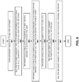
- FIG. 6 A method in accordance with one embodiment of the invention is illustrated in Figure 6 .
- the method may be implemented within the context of the architecture shown in Figure 5 , but is not limited to any specific system architecture.
- the user opens a browser and navigates to the SSL VPN gateway.
- the SSL VPN gateway renders the page containing browser-executable code to trigger authentication on the client.
- the browser-executable code establishes a connection with an authentication server to trigger authentication of the user.
- the browser-executable code exchanges messages between the authentication client and authentication server to authenticate the user (see, e.g., description above with respect to Figures 1A-B , 3 , and 5 ). Once authenticated, the authentication server returns a ticket.
- the browser-executable code submits the ticket to the SSL VPN gateway and, at 606, the SSL VPN gateway validates the ticket against the authentication server. As mentioned above, this may involve the authentication server comparing the ticket to the ticket returned in operation 604 to confirm the validity of the ticket (e.g., via RADIUS).
- the SSL VPN gateway grants the user access to the protected internal network.
- elements of the authentication client 201 are integrated into the legacy solution's client side software to achieve the integration; however, as before, no server-side integration is necessary.
- the authentication client 201 is equipped with a credential provider component 711 for managing signed certificates, which it uses to gain access to network resources via a Kerberos infrastructure 730.
- the authentication client 201 may be integrated into the Windows® operating system via the Credential Provider Framework using the credential provider component 730. It should be noted, however, that the underlying principles of the invention are not limited to a Kerberos implementation or any particular type of operating system.
- This embodiment also relies on communication between the authentication server 725 and authentication client 201 which enter into a series of authentication transactions to authenticate the end user (e.g., as described above with respect to Figures 1B and 3 ).
- the active directory 735 and Kerberos infrastructure 730 are configured to trust the root certificate held by the authentication server 725.
- the authentication server 725 issues a short-lived certificate comprising a cryptographic public/private key pair which it signs using a root certificate held by the authentication server 725 (e.g., signing the short-lived certificate with the private key of the root certificate).
- the public key of the short-lived certificate is signed with the private key of the root certificate.
- the short-lived certificate may also include timestamp/timeout data indicating a length of time for which the short-lived certificate is valid (e.g., 5 minutes, 1 hour, etc).
- the credential provider 711 receives the signed short-lived certificate from the authentication server, it enters into a challenge response transaction with the Kerberos infrastructure 730 involving the short-lived certificate.
- the Kerberos infrastructure sends a challenge (e.g., random data such as a nonce) to the credential provider 711 which then signs the challenge using the private key of the short-lived certificate. It then sends the short-lived certificate to the Kerberos infrastructure which (1) validates the signature on the short-lived certificate using the public key of the root certificate provided by the authentication server 725 (which it has been configured to trust); and (2) validates the signature over the challenge using the public key from the short-lived certificate. If both signatures are valid, then the Kerberos infrastructure issues a Kerberos ticket to the credential provider 711 which it may then use to gain access to network resources such as file servers, email accounts, etc, managed by the Kerberos infrastructure.
- a challenge e.g., random data such as a nonce
- the authentication server 725 and client 201 may be integrated without significant modification to the existing active directory 735 and Kerberos infrastructure 730. Rather, all that is required is that the active directory 735/Kerberos infrastructure are configured to trust the root certificate held by the authentication server 725.
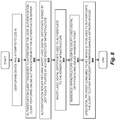
- Figure 8 illustrates one embodiment of a method for integrating an online authentication infrastructure with a legacy system. The method may be implemented within the context of the architecture shown in Figure 7 , but is not limited to any particular system architecture.
- the user opens a device such as a Windows device and attempts to log in.
- an authentication client is triggered to authenticate the user.
- the authentication client performs online authentication with an authentication server.
- the authentication client may have previously registered one or more authentication devices with the server (e.g., a fingerprint authentication device, a voice authentication device, etc). It may then authenticate with the server using a series of transactions such as those described above with respect to Figures 1A-B and 3 .
- the authentication server may send the authentication client an authentication request with a random challenge, which the authentication client signs using a private key associated with the authentication device used. The authentication server may then use the public key to validate the signature.
- the authentication server if authentication is successful, then at 803, the authentication server returns a short-lived digital certificate to the authentication client which is signed using a private key of a root certificate maintained by the authentication server.
- the root certificate is trusted by the active directory/Kerberos infrastructure.
- the authentication client then uses the short-lived digital certificate to authenticate to the Kerberos infrastructure.
- the Kerberos infrastructure may send a challenge (e.g., random data such as a nonce) to the authentication client which then signs the challenge using the private key of the short-lived certificate. It then sends the short-lived certificate to the Kerberos infrastructure which, at 805, validates the signature on the short-lived certificate using the public key of the root certificate provided by the authentication server (which it has been configured to trust); and validates the signature over the challenge using the public key from the short-lived certificate. If both signatures are valid, then the Kerberos infrastructure issues a Kerberos ticket to the authentication client which, at 806, it may then use to gain access to network resources such as file servers, email accounts, etc, managed by the Kerberos infrastructure.
- a Kerberos ticket e.g., a Kerberos ticket
- Reduction in initial integration effort Allows a Relying Party to deploy online authentication without re-writing their application to incorporate the online authentication functionality, or to enable integration with a third-party federation server.
- Simplification of policy administration By expressing the authentication policy outside of code, this approach allows the organization to easily update their authentication policies without requiring code changes. Changes to reflect new interpretations of regulatory mandates, or to respond to attacks on existing authentication mechanisms become a simple change in the policy, and can be effected quickly.
- Enablement of future refinement As new authentication devices and mechanisms become available, an organization can evaluate the appropriateness of the devices/mechanisms when addressing new or emerging risks. Integrating a newly-available authentication device only requires adding the device to a policy; no new code has to be written to deploy the new capability immediately, even to legacy applications.
- OTP approaches typically require an IT administrator to provision the end user's token with the OTP validation server; software-based desktop OTP generators still require helpdesk intervention during initial deployment.
- the online authentication approach can dramatically reduce the deployment costs by leveraging capabilities already available on the end user's device, and delivering a self-service enrollment model for deployment.
- OTP approaches require the user to not only carry their OTP generator (which many forget, resulting in additional helpdesk costs to enable temporary access) but also to manually input the OTP into the application.
- the FIDO approach can dramatically reduce the impact of authentication on the end user by replacing user name / password and OTP entry with something simpler, like swiping a finger over a fingerprint sensor.
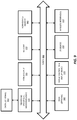
- Figure 9 is a block diagram illustrating an exemplary clients and servers which may be used in some embodiments of the invention. It should be understood that while Figure 9 illustrates various components of a computer system, it is not intended to represent any particular architecture or manner of interconnecting the components as such details are not germane to the present invention. It will be appreciated that other computer systems that have fewer components or more components may also be used with the present invention.
- the computer system 900 which is a form of a data processing system, includes the bus(es) 950 which is coupled with the processing system 920, power supply 925, memory 930, and the nonvolatile memory 940 (e.g., a hard drive, flash memory, Phase-Change Memory (PCM), etc.).
- the bus(es) 950 may be connected to each other through various bridges, controllers, and/or adapters as is well known in the art.
- the processing system 920 may retrieve instruction(s) from the memory 930 and/or the nonvolatile memory 940, and execute the instructions to perform operations as described above.
- the bus 950 interconnects the above components together and also interconnects those components to the optional dock 960, the display controller & display device 990, Input/Output devices 980 (e.g., NIC (Network Interface Card), a cursor control (e.g., mouse, touchscreen, touchpad, etc.), a keyboard, etc.), and the optional wireless transceiver(s) 990 (e.g., Bluetooth, WiFi, Infrared, etc.).
- NIC Network Interface Card
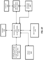
- Figure 10 is a block diagram illustrating an exemplary data processing system which may be used in some embodiments of the invention.
- the data processing system 1000 may be a handheld computer, a personal digital assistant (PDA), a mobile telephone, a portable gaming system, a portable media player, a tablet or a handheld computing device which may include a mobile telephone, a media player, and/or a gaming system.
- the data processing system 1000 may be a network computer or an embedded processing device within another device.
- the exemplary architecture of the data processing system 1000 may be used for the mobile devices described above.
- the data processing system 1000 includes the processing system 1020, which may include one or more microprocessors and/or a system on an integrated circuit.
- the processing system 1020 is coupled with a memory 1010, a power supply 1025 (which includes one or more batteries) an audio input/output 1040, a display controller and display device 1060, optional input/output 1050, input device(s) 1070, and wireless transceiver(s) 1030.
- additional components not shown in Figure 10
- one or more buses, not shown in Figure 10 may be used to interconnect the various components as is well known in the art.
- the memory 1010 may store data and/or programs for execution by the data processing system 1000.
- the audio input/output 1040 may include a microphone and/or a speaker to, for example, play music and/or provide telephony functionality through the speaker and microphone.
- the display controller and display device 1060 may include a graphical user interface (GUI).
- the wireless (e.g., RF) transceivers 1030 e.g., a WiFi transceiver, an infrared transceiver, a Bluetooth transceiver, a wireless cellular telephony transceiver, etc.
- the one or more input devices 1070 allow a user to provide input to the system. These input devices may be a keypad, keyboard, touch panel, multi touch panel, etc.
- the optional other input/output 1050 may be a connector for a dock.
- Embodiments of the invention may include various steps as set forth above.
- the steps may be embodied in machine-executable instructions which cause a general-purpose or special-purpose processor to perform certain steps.
- these steps may be performed by specific hardware components that contain hardwired logic for performing the steps, or by any combination of programmed computer components and custom hardware components.
- Elements of the present invention may also be provided as a machine-readable medium for storing the machine-executable program code.
- the machine-readable medium may include, but is not limited to, floppy diskettes, optical disks, CD-ROMs, and magneto-optical disks, ROMs, RAMs, EPROMs, EEPROMs, magnetic or optical cards, or other type of media/machine-readable medium suitable for storing electronic program code.
- Embodiments of the invention may include various steps as set forth above.
- the steps may be embodied in machine-executable instructions which cause a general-purpose or special-purpose processor to perform certain steps.
- these steps may be performed by specific hardware components that contain hardwired logic for performing the steps, or by any combination of programmed computer components and custom hardware components.
Description
- This invention relates generally to the field of data processing systems. More particularly, the invention relates to a system and method for integrating an authentication service within a network architecture.
- Systems have also been designed for providing secure user authentication over a network using biometric sensors. In such systems, the a score generated by an authenticator, and/or other authentication data, may be sent over a network to authenticate the user with a remote server. For example, Patent Application No.
2011/0082801 ("'801 Application") describes a framework for user registration and authentication on a network which provides strong authentication (e.g., protection against identity theft and phishing), secure transactions (e.g., protection against "malware in the browser" and "man in the middle" attacks for transactions), and enrollment/management of client authentication tokens (e.g., fingerprint readers, facial recognition devices, smartcards, trusted platform modules, etc). - The assignee of the present application has developed a variety of improvements to the authentication framework described in the '801 application. Some of these improvements are described in the following set of US Patent Applications, which are assigned to the present assignee: Serial No.
13/730,761 13/730,776 13/730,780 13/730,791 13/730,795 14/218,504 - Briefly, the Co-Pending applications describe authentication techniques in which a user enrolls with authentication devices (or Authenticators) such as biometric devices (e.g., fingerprint sensors) on a client device. When a user enrolls with a biometric device, biometric reference data is captured (e.g., by swiping a finger, snapping a picture, recording a voice, etc). The user may subsequently register/provision the authentication devices with one or more servers over a network (e.g., Websites or other relying parties equipped with secure transaction/authentication services as described in the Co-Pending Applications); and subsequently authenticate with those servers using data exchanged during the registration process (e.g., cryptographic keys provisioned into the authentication devices). Once authenticated, the user is permitted to perform one or more online transactions with a Website or other relying party. In the framework described in the Co-Pending Applications, sensitive information such as fingerprint data and other data which can be used to uniquely identify the user, may be retained locally on the user's authentication device to protect a user's privacy.
- The '504 Application describes a variety of additional techniques including techniques for designing composite authenticators, intelligently generating authentication assurance levels, using non-intrusive user verification, transferring authentication data to new authentication devices, augmenting authentication data with client risk data, and adaptively applying authentication policies, and creating trust circles, to name just a few.
- Augmenting a Relying Party's web-based or other network enabled application to leverage the remote authentication techniques described in the co-pending applications typically requires the application to integrate directly with an authentication server. This poses a barrier to the adoption of such authentication, as Relying Parties will need to expend effort to update their applications to integrate with an authentication server in order to gain the authentication flexibility provided by the techniques described in the co-pending applications.
- In some cases, the Relying Party may have already integrated with federation solutions, and thus a simple integration path is to simply integrate online authentication support into the federation solution. Unfortunately, this approach does not address other legacy systems (such as VPNs, Windows Kerberos deployments) that either lack awareness of federation protocols (and thus could be front-ended by a federation server augmented with online authentication functionality), or lack sufficient extensibility to enable direct integration of online authentication functionality. Hence, a key problem that must be solved for certain Relying Party applications is finding a way to enable them to integrate online authentication systems, without requiring the code for the applications themselves to be modified.
- Prior art document
US 8 584 224 B1 discloses a system for authenticating a user to a relying party. A user sends an access request to a relying party web application. In response, the application sends a page with JavaScript that detects a plug-in at the user and detects the relying party domain. The plug-in uses its device certificate or other pre-established credentials to sign a challenge along with other site and user information including the site domain, the authentication service URL and user identifier, and send it, along with the data including the domain and the user identifier, to an authentication service. The service authenticates the information and sends back to the plug-in a short ticket that can be passed on to the relying party, which can validate it using the Radius protocol and an authentication service call, thereby authenticating the user. - Prior art document
US 2014/189828 A1 discloses a system, apparatus, method, and machine readable for transparently requesting a new random challenge from a server within an authentication framework. For example, one embodiment of a method comprises: transmitting a random challenge and an indication of a timeout period associated with the random challenge from a server to a client within the context of a network registration or authentication process using authentication devices communicatively coupled to the client; automatically detecting that the random challenge is no longer valid based on the timeout period; and responsively transmitting a request for a new random challenge from the client to a server, wherein transmitting is performed transparently to a user of the client. - The present invention is defined by the appended independent claims 1 and 6.
- A better understanding of the present invention can be obtained from the following detailed description in conjunction with the following drawings, in which:
-
FIGS. 1A-B illustrate two different embodiments of a secure authentication system architecture; -
FIG. 2 is a transaction diagram showing how keys may be registered into authentication devices; -
FIG. 3 illustrates a transaction diagram showing remote authentication; -
FIG. 4 illustrates a system for connecting a user to an internal network through a secure sockets layer (SSL) virtual private network (VPN) gateway; -
FIG. 5 illustrates one embodiment of a system for integrating an authentication server within a network infrastructure; -
FIG. 6 illustrates one embodiment of a method for performing authentication using an authentication server integrated within a network infrastructure; -
FIG. 7 illustrates one embodiment of a system for integrating an authentication server within a Kerberos infrastructure; -
FIG. 8 illustrates one embodiment of a method for performing authentication using an authentication server integrated within a Kerberos infrastructure; -
FIG. 9 illustrates one embodiment of a computer architecture used for servers and/or clients; and -
FIG. 10 illustrates one embodiment of a computer architecture used for servers and/or clients. - Described below are embodiments of an apparatus, method, and machine-readable medium for implementing advanced authentication techniques and associated applications. Throughout the description, for the purposes of explanation, numerous specific details are set forth in order to provide a thorough understanding of the present invention. It will be apparent, however, to one skilled in the art that the present invention may be practiced without some of these specific details. In other instances, well-known structures and devices are not shown or are shown in a block diagram form to avoid obscuring the underlying principles of the present invention.
- The embodiments of the invention discussed below involve authentication devices with user verification capabilities such as biometric modalities or PIN entry. These devices are sometimes referred to herein as "tokens," "authentication devices," or "authenticators." While certain embodiments focus on facial recognition hardware/software (e.g., a camera and associated software for recognizing a user's face and tracking a user's eye movement), some embodiments may utilize additional biometric devices including, for example, fingerprint sensors, voice recognition hardware/software (e.g., a microphone and associated software for recognizing a user's voice), and optical recognition capabilities (e.g., an optical scanner and associated software for scanning the retina of a user). The user verification capabilities may also include non-biometric modalities, like PIN entry. The authenticators might use devices like trusted platform modules (TPMs), smartcards and secure elements for cryptographic operations and key storage.
- In a mobile biometric implementation, the biometric device may be remote from the relying party. As used herein, the term "remote" means that the biometric sensor is not part of the security boundary of the computer it is communicatively coupled to (e.g., it is not embedded into the same physical enclosure as the relying party computer). By way of example, the biometric device may be coupled to the relying party via a network (e.g., the Internet, a wireless network link, etc) or via a peripheral input such as a USB port. Under these conditions, there may be no way for the relying party to know if the device is one which is authorized by the relying party (e.g., one which provides an acceptable level of authentication strength and integrity protection) and/or whether a hacker has compromised or even replaced the biometric device. Confidence in the biometric device depends on the particular implementation of the device.
- The term "local" is used herein to refer to the fact that the user is completing a transaction in person, at a particular location such as at an automatic teller machine (ATM) or a point of sale (POS) retail checkout location. However, as discussed below, the authentication techniques employed to authenticate the user may involve non-location components such as communication over a network with remote servers and/or other data processing devices. Moreover, while specific embodiments are described herein (such as an ATM and retail location) it should be noted that the underlying principles of the invention may be implemented within the context of any system in which a transaction is initiated locally by an end user.
- The term "relying party" is sometimes used herein to refer, not merely to the entity with which a user transaction is attempted (e.g., a Website or online service performing user transactions), but also to the secure transaction servers (sometimes referred to as "au implemented on behalf of that entity which may performed the underlying authentication techniques described herein. The secure transaction servers may be owned and/or under the control of the relying party or may be under the control of a third party offering secure transaction services to the relying party as part of a business arrangement.
- The term "server" is used herein to refer to software executed on a hardware platform (or across multiple hardware platforms) that receives requests over a network from a client, responsively performs one or more operations, and transmits a response to the client, typically including the results of the operations. The server responds to client requests to provide, or help to provide, a network "service" to the clients. Significantly, a server is not limited to a single computer (e.g., a single hardware device for executing the server software) and may, in fact, be spread across multiple hardware platforms, potentially at multiple geographical locations.
-
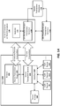
Figures 1A-B illustrate two embodiments of a system architecture comprising client-side and server-side components for registering authentication devices (also sometimes referred to as "provisioning") and authenticating a user. The embodiment shown inFigure 1A uses a web browser plugin-based architecture for communicating with a website while the embodiment shown inFigure 1B does not require a web browser. The various techniques described herein such as enrolling a user with authentication devices, registering the authentication devices with a secure server, and verifying a user may be implemented on either of these system architectures. Thus, while the architecture shown inFigure 1A is used to demonstrate the operation of several of the embodiments described below, the same basic principles may be easily implemented on the system shown inFigure 1B (e.g., by removing thebrowser plugin 105 as the intermediary for communication between theserver 130 and thesecure transaction service 101 on the client). - Turning first to
Figure 1A , the illustrated embodiment includes aclient 100 equipped with one or more authentication devices 110-112 (sometimes referred to in the art as authentication "tokens" or "Authenticators") for enrolling and verifying an end user. As mentioned above, the authentication devices 110-112 may include biometric device such as fingerprint sensors, voice recognition hardware/software (e.g., a microphone and associated software for recognizing a user's voice), facial recognition hardware/software (e.g., a camera and associated software for recognizing a user's face), and optical recognition capabilities (e.g., an optical scanner and associated software for scanning the retina of a user) and support for non-biometric modalities, such as PIN verification. The authentication devices might use trusted platform modules (TPMs), smartcards or secure elements for cryptographic operations and key storage. - The authentication devices 110-112 are communicatively coupled to the client through an interface 102 (e.g., an application programming interface or API) exposed by a
secure transaction service 101. Thesecure transaction service 101 is a secure application for communicating with one or more secure transaction servers 132-133 over a network and for interfacing with asecure transaction plugin 105 executed within the context of aweb browser 104. As illustrated, theInterface 102 may also provide secure access to asecure storage device 120 on theclient 100 which stores information related to each of the authentication devices 110-112 such as a device identification code, user identification code, user enrollment data (e.g., scanned fingerprint or other biometric data) protected by he authentication device, and keys wrapped by the authentication device used to perform the secure authentication techniques described herein. For example, as discussed in detail below, a unique key may be stored into each of the authentication devices and used when communicating toservers 130 over a network such as the Internet. - As discussed below, certain types of network transactions are supported by the
secure transaction plugin 105 such as HTTP or HTTPS transactions withwebsites 131 or other servers. In one embodiment, the secure transaction plugin is initiated in response to specific HTML tags inserted into the HTML code of a web page by theweb server 131 within the secure enterprise or Web destination 130 (sometimes simply referred to below as "server 130"). In response to detecting such a tag, thesecure transaction plugin 105 may forward transactions to thesecure transaction service 101 for processing. In addition, for certain types of transactions (e.g., such as secure key exchange) thesecure transaction service 101 may open a direct communication channel with the on-premises transaction server 132 (i.e., co-located with the website) or with an off-premises transaction server 133. - The secure transaction servers 132-133 are coupled to a
secure transaction database 120 for storing user data, authentication device data, keys and other secure information needed to support the secure authentication transactions described below. It should be noted, however, that the underlying principles of the invention do not require the separation of logical components within the secure enterprise orweb destination 130 shown inFigure 1A . For example, thewebsite 131 and the secure transaction servers 132-133 may be implemented within a single physical server or separate physical servers. Moreover, thewebsite 131 and transaction servers 132-133 may be implemented within an integrated software module executed on one or more servers for performing the functions described below. - As mentioned above, the underlying principles of the invention are not limited to a browser-based architecture shown in
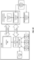
Figure 1A .Figure 1B illustrates an alternate implementation in which a stand-alone application 154 utilizes the functionality provided by thesecure transaction service 101 to authenticate a user over a network. In one embodiment, theapplication 154 is designed to establish communication sessions with one or more network services 151 which rely on the secure transaction servers 132-133 for performing the user/client authentication techniques described in detail below. - In either of the embodiments shown in
Figures 1A-B , the secure transaction servers 132-133 may generate the keys which are then securely transmitted to thesecure transaction service 101 and stored into the authentication devices within thesecure storage 120. Additionally, the secure transaction servers 132-133 manage thesecure transaction database 120 on the server side. - Certain basic principles associated with remotely registering authentication devices and authenticating with a relying party will be described with respect to
Figures 2-3 , followed by a detailed description of embodiments of the invention for establishing trust using secure communication protocols. -
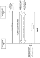
Figure 2 illustrates a series of transactions for registering authentication devices on a client (such as devices 110-112 onclient 100 inFigures 1A-B ) (sometimes referred to as "provisioning" authentication devices). For simplicity, thesecure transaction service 101 andinterface 102 are combined together asauthentication client 201 and the secure enterprise orweb destination 130 including the secure transaction servers 132-133 are represented as a relyingparty 202. - During registration of an authenticator (e.g., a fingerprint authenticator, voice authenticator, etc), a key associated with the authenticator is shared between the
authentication client 201 and the relyingparty 202. Referring back toFigures 1A-B , the key may be stored within thesecure storage 120 of theclient 100 and thesecure transaction database 120 used by the secure transaction servers 132-133. In one embodiment, the key is a symmetric key generated by one of the secure transaction servers 132-133. However, in another embodiment discussed below, asymmetric keys are be used. In this embodiment, the public/private key pair may be generated by the secure transaction servers 132-133. The public key may then be stored by the secure transaction servers 132-133 and the related private key may be stored in thesecure storage 120 on the client. In an alternate embodiment, the key(s) may be generated on the client 100 (e.g., by the authentication device or the authentication device interface rather than the secure transaction servers 132-133). The underlying principles of the invention are not limited to any particular types of keys or manner of generating the keys. - A secure key provisioning protocol is employed in one embodiment to share the key with the client over a secure communication channel. One example of a key provisioning protocol is the Dynamic Symmetric Key Provisioning Protocol (DSKPP) (see, e.g., Request for Comments (RFC) 6063). However, the underlying principles of the invention are not limited to any particular key provisioning protocol. In one particular embodiment, the client generates a public/private key pair and sends the public key to the server, which may be attested with an attestation key.
- Turning to the specific details shown in
Figure 2 , to initiate the registration process, the relyingparty 202 generates a randomly generated challenge (e.g., a cryptographic nonce) that must be presented by theauthentication client 201 during device registration. The random challenge may be valid for a limited period of time. In response, theauthentication client 201 initiates an out-of-band secure connection with the relying party 202 (e.g., an out-of-band transaction) and communicates with the relyingparty 202 using the key provisioning protocol (e.g., the DSKPP protocol mentioned above). To initiate the secure connection, theauthentication client 201 may provide the random challenge back to the relying party 202 (potentially with a signature generated over the random challenge). In addition, theauthentication client 201 may transmit the identity of the user (e.g., a user ID or other code) and the identity of the authentication device(s) to be provisioned registered (e.g., using the authentication attestation ID (AAID) which uniquely identify the type of authentication device(s) being provisioned). - The relying party locates the user with the user name or ID code (e.g., in a user account database), validates the random challenge (e.g., using the signature or simply comparing the random challenge to the one that was sent), validates the authentication device's authentication code if one was sent (e.g., the AAID), and creates a new entry in a secure transaction database (e.g.,
database 120 inFigures 1A-B ) for the user and the authentication device(s). In one embodiment, the relying party maintains a database of authentication devices which it accepts for authentication. It may query this database with the AAID (or other authentication device(s) code) to determine if the authentication device(s) being provisioned are acceptable for authentication. If so, then it will proceed with the registration process. - In one embodiment, the relying
party 202 generates an authentication key for each authentication device being provisioned. It writes the key to the secure database and sends the key back to theauthentication client 201 using the key provisioning protocol. Once complete, the authentication device and the relyingparty 202 share the same key if a symmetric key was used or different keys if asymmetric keys were used. For example, if asymmetric keys were used, then the relyingparty 202 may store the public key and provide the private key to theauthentication client 201. Upon receipt of the private key from the relyingparty 202, theauthentication client 201 provisions the key into the authentication device (storing it within secure storage associated with the authentication device). It may then use the key during authentication of the user (as described below). In an alternate embodiment, the key(s) are generated by theauthentication client 201 and the key provisioning protocol is used to provide the key(s) to the relyingparty 202. In either case, once provisioning is complete, theauthentication client 201 and relyingparty 202 each have a key and theauthentication client 201 notifies the relying party of the completion. -
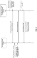
Figure 3 illustrates a series of transactions for user authentication with the provisioned authentication devices. Once device registration is complete (as described inFigure 2 ), the relyingparty 202 will accept an authentication response (sometimes referred to as a "token") generated by the local authentication device on the client as a valid authentication response. - Turning to the specific details shown in
Figure 3 , in response to the user initiating a transaction with the relyingparty 202 which requires authentication (e.g., initiating payment from the relying party's website, accessing private user account data, etc), the relyingparty 202 generates an authentication request which includes a random challenge (e.g., a cryptographic nonce). In one embodiment, the random challenge has a time limit associated with it (e.g., it is valid for a specified period of time). The relying party may also identify the authenticator to be used by theauthentication client 201 for authentication. As mentioned above, the relying party may provision each authentication device available on the client and stores a public key for each provisioned authenticator. Thus, it may use the public key of an authenticator or may use an authenticator ID (e.g., AAID) to identify the authenticator to be used. Alternatively, it may provide the client with a list of authentication options from which the user may select. - In response to receipt of the authentication request, the user may be presented with a graphical user interface (GUI) requesting authentication (e.g., in the form of a web page or a GUI of an authentication application/app). The user then performs the authentication (e.g., swiping a finger on a fingerprint reader, etc). In response, the
authentication client 201 generates an authentication response containing a signature over the random challenge with the private key associated with the authenticator. It may also include other relevant data such as the user ID code in the authentication response. - Upon receipt of the authentication response, the relying party may validate the signature over the random challenge (e.g., using the public key associated with the authenticator) and confirm the identity of the user. Once authentication is complete, the user is permitted to enter into secure transactions with the relying party, as illustrated.
- A secure communication protocol such as Transport Layer Security (TLS) or Secure Sockets Layer (SSL) may be used to establish a secure connection between the relying
party 201 and theauthentication client 202 for any or all of the transactions illustrated inFigures 2-3 . - Many legacy systems may feature support for an authentication methods other than usernames and passwords. For example, secure sockets layer (SSL) virtual private network (VPN) systems support the use of One Time Passwords (OTPs). Systems such as Kerberos allow the user to authenticate to a network or service using a digital certificate.
- The embodiments of the invention described herein leverage these features to integrate an online authentication service with such legacy systems without requiring any changes to the legacy system itself (other than configuration changes).
- To augment the security of secure socket layer (SSL) virtual private networks (VPNs), enterprises deploy second factor authentication solutions based on OTP approaches. Solutions such as RSA SecurlD or OATH require the user to carry an OTP generator and input the OTP generated by this generator in combination with the username and password to authenticate to VPN.
-
Figure 4 illustrates an OTP validation server 425 configured to operate in combination with anSSL VPN gateway 415. In operation, the user opens aweb browser 410 and navigates to theSSL VPN gateway 415 which renders an HTML-basedlogin form 411 containing auser ID field 412 andpassword field 413. The user may enter a user ID in theUID field 412 and the OTP in the password field 413 (either by itself or appended to the user's static password). After entering the user name and password via theHTML form 411, the user submits the results to theSSL VPN gateway 415. - The
SSL VPN gateway 415 validates the username and password against a user store 420 (e.g., verifying the user name exists and that the correct password was entered) and validates the OTP by providing the OTP entered by the user to the OTP validation server 425. If the OTP validation server 425 provides an affirmative response, validating the OTP, theSSL VPN gateway 415 grants the user access to the protectedinternal network 430. - As mentioned, in the above example, the
SSL VPN gateway 415 may render a separate form element to enable input of the OTP while, in other cases, theSSL VPN gateway 415 may simply rely on the user appending their OTP to the password in the form's password field. In addition, theSSL VPN gateway 415 may immediately reject access if the primary username and password are not accepted by the user store 420 validation. Communication between theSSL VPN gateway 415 and the OTP validation server 425 may be facilitated by a plugin provided by either the SSL VPN gateway vendor or the OTP validation server vendor. However the majority of SSL VPN gateways support Remote Authentication Dial In User Service (RADIUS; see RFC 2865) integration. Thus, RADIUS support by the OTP solution obviates the need for the OTP server provider to develop SSL VPN gateway-specific connectors. - As illustrated in
Figure 5 , one embodiment of the invention relies on existing features of theSSL VPN gateway 515 to integrate online authentication techniques (e.g., such as those described above with respect toFigures 1A-B and3 ) without altering the network infrastructure. As illustrated, this embodiment includes anauthentication server 202 communicatively coupled to theSSL VPN gateway 515, potentially in the same (or a similar) manner as the OTP validation server 425 described above. Theauthentication server 202 is also communicatively coupled to aclient device 510 with anauthentication client 201 for authenticating a user using one or more authentication devices 110-112 (e.g., fingerprint authenticators, voice authenticators, retinal scanning authenticators, etc). While theauthentication server 202 is coupled to theauthentication client 201 via a browser inFigure 5 (e.g., in a similar manner as the embodiment shown inFigure 1A ), the underlying principles of the invention are not limited to a browser-based implementation. - In one embodiment, the interaction between the
SSL VPN gateway 515,browser 510, andauthentication server 202 is as follows. A user opens theweb browser 510 and navigates to theSSL VPN gateway 515 which renders aweb page 511 containing browser-executable code 512 such as JavaScript. In one embodiment, the browser-executable code 512 triggers authentication by establishing a communication channel with theauthentication server 202 and triggering theauthentication client 201 to authenticate the user. In one embodiment, theauthentication server 202 andclient 201 enter into a series of authentication transactions such as those described above with respect toFigure 3 . For example, theauthentication server 202 may generate an authentication request which includes a random challenge (e.g., a cryptographic nonce) and may (or may not) identify the authenticator 110-112 to be used by theauthentication client 201 for authentication. In response to receipt of the authentication request, the user may be presented with a graphical user interface (GUI) requesting authentication (e.g., in the form of a web page or a GUI of an authentication application/app). The user then performs the authentication (e.g., swiping a finger on a fingerprint reader, etc). In response, theauthentication client 201 generates an authentication response containing a signature over the random challenge with the private key associated with the authenticator. It may also include other relevant data such as the user ID code in the authentication response. Upon receipt of the authentication response, theauthentication server 202 validates the signature over the random challenge (e.g., using the public key associated with the authenticator) and confirms the identity of the user. In one embodiment, the JavaScript or other browser executable code 512 passes the above authentication messages between theauthentication server 202 andauthentication client 201. - In one embodiment, in response to a successful authentication, the
authentication server 202 generates and passes a cryptographic data structure, referred to herein as a "ticket," to thebrowser 510. In one embodiment, the ticket comprises a random string of digits or other form of one time password (OTP) capable of being submitted to theSSL VPN gateway 515 via the fields of theHTML form 511. For example, as mentioned above, a separate field may be defined in theHTML form 511 for the ticket or the ticket may be appended to the end of the user's static password. Regardless of how the ticket is entered, in one embodiment, the JavaScript or other browser executable code 512 submits ticket to theSSL VPN gateway 515. Once received, theSSL VPN gateway 515 validates the ticket via communication with the authentication server 202 (e.g., providing the ticket to the authentication server and receiving a communication indicating that the ticket is valid). For example, upon receipt of the ticket and other user data from the SSL VPN gateway 515 (e.g., the user ID or other form of identifier), theauthentication server 202 may compare the ticket with the ticket provided to thebrowser 510. If the tickets match, then theauthentication server 202 sends an "authentication success" message to theSSL VPN gateway 515. If the tickets do not match, then the authentication server sends an "authentication failure" message to theSSL VPN gateway 515. In one embodiment, theSSL VPN gateway 515 validates the ticket against theauthentication server 202 using RADIUS (although the underlying principles of the invention are not limited to any specific protocol). Once validated, theSSL VPN gateway 515 grants the user access to the protectedinternal network 530. - Significantly, the transactions between the
SSL VPN gateway 515 andauthentication server 202 may be implemented in the same manner (e.g., using the same protocols and data fields) as the success/failure messages provided by the OTP validation server 425. As a result, theSSL VPN gateway 515 does not need to be reconfigured to implement the embodiments of the invention described herein, thereby simplifying the implementation and reducing the time and expense associated therewith. - In the above approach, the SSL
VPN login page 511 may be customized to include custom JavaScript or other browser executable code 512 to trigger the authentication. Of course, alternate embodiments may be implemented in the event that the user does not have theauthentication client 201 installed. - In addition, communication with the
SSL VPN gateway 515 by the JavaScript or other browser executable code 512 may be facilitated through thesame HTML form 511 that the user would normally use to authenticate to theSSL VPN gateway 515. The goal would be to pass the ticket obtained by the JavaScript or other executable code using the existing password or OTP fields in the default SSL VPN's HTML form 511 (once again, simplifying and reducing the time and expense associated with implementing the above techniques). - Because these techniques address a well defined problem for a large number of VPN solutions without developing VPN-specific integrations, achieving this integration would require relatively little effort, and allow the authentication service provider (i.e., the entity managing the
authentication server 202 and client 201) to provide a packaged solution for delivering secure remote access. - A method in accordance with one embodiment of the invention is illustrated in
Figure 6 . The method may be implemented within the context of the architecture shown inFigure 5 , but is not limited to any specific system architecture. - At 601, the user opens a browser and navigates to the SSL VPN gateway. At 602, the SSL VPN gateway renders the page containing browser-executable code to trigger authentication on the client. At 603, the browser-executable code establishes a connection with an authentication server to trigger authentication of the user. At 604, the browser-executable code exchanges messages between the authentication client and authentication server to authenticate the user (see, e.g., description above with respect to
Figures 1A-B ,3 , and5 ). Once authenticated, the authentication server returns a ticket. - At 605, the browser-executable code submits the ticket to the SSL VPN gateway and, at 606, the SSL VPN gateway validates the ticket against the authentication server. As mentioned above, this may involve the authentication server comparing the ticket to the ticket returned in
operation 604 to confirm the validity of the ticket (e.g., via RADIUS). At 607, once the ticket is validated, the SSL VPN gateway grants the user access to the protected internal network. - An alternative approach to integrating with legacy systems is possible in cases where the legacy system accepts the use of digital certificates for authentication. These solutions, such as VPNs or Windows Active Directory using Kerberos, typically involve a client-side component to perform the certificate authentication.
- Unlike the integration approach outlined above, where the integration on the client side was primarily browser-based (e.g., using JavaScript), in this embodiment, elements of the
authentication client 201 are integrated into the legacy solution's client side software to achieve the integration; however, as before, no server-side integration is necessary. - In the specific embodiment shown in
Figure 7 , theauthentication client 201 is equipped with acredential provider component 711 for managing signed certificates, which it uses to gain access to network resources via aKerberos infrastructure 730. For example, in one embodiment, theauthentication client 201 may be integrated into the Windows® operating system via the Credential Provider Framework using thecredential provider component 730. It should be noted, however, that the underlying principles of the invention are not limited to a Kerberos implementation or any particular type of operating system. - This embodiment also relies on communication between the authentication server 725 and
authentication client 201 which enter into a series of authentication transactions to authenticate the end user (e.g., as described above with respect toFigures 1B and3 ). In one embodiment, theactive directory 735 andKerberos infrastructure 730 are configured to trust the root certificate held by the authentication server 725. Once the user is authenticated, the authentication server 725 issues a short-lived certificate comprising a cryptographic public/private key pair which it signs using a root certificate held by the authentication server 725 (e.g., signing the short-lived certificate with the private key of the root certificate). In particular, in one embodiment, the public key of the short-lived certificate is signed with the private key of the root certificate. In addition to the key pairs, the short-lived certificate may also include timestamp/timeout data indicating a length of time for which the short-lived certificate is valid (e.g., 5 minutes, 1 hour, etc). - In one embodiment, once the
credential provider 711 receives the signed short-lived certificate from the authentication server, it enters into a challenge response transaction with theKerberos infrastructure 730 involving the short-lived certificate. In particular, the Kerberos infrastructure sends a challenge (e.g., random data such as a nonce) to thecredential provider 711 which then signs the challenge using the private key of the short-lived certificate. It then sends the short-lived certificate to the Kerberos infrastructure which (1) validates the signature on the short-lived certificate using the public key of the root certificate provided by the authentication server 725 (which it has been configured to trust); and (2) validates the signature over the challenge using the public key from the short-lived certificate. If both signatures are valid, then the Kerberos infrastructure issues a Kerberos ticket to thecredential provider 711 which it may then use to gain access to network resources such as file servers, email accounts, etc, managed by the Kerberos infrastructure. - Using these techniques, the authentication server 725 and
client 201 may be integrated without significant modification to the existingactive directory 735 andKerberos infrastructure 730. Rather, all that is required is that theactive directory 735/Kerberos infrastructure are configured to trust the root certificate held by the authentication server 725. -
Figure 8 illustrates one embodiment of a method for integrating an online authentication infrastructure with a legacy system. The method may be implemented within the context of the architecture shown inFigure 7 , but is not limited to any particular system architecture. - At 801, the user opens a device such as a Windows device and attempts to log in. At 802, an authentication client is triggered to authenticate the user. In response, the authentication client performs online authentication with an authentication server. For example, as discussed above, the authentication client may have previously registered one or more authentication devices with the server (e.g., a fingerprint authentication device, a voice authentication device, etc). It may then authenticate with the server using a series of transactions such as those described above with respect to
Figures 1A-B and3 . For example, the authentication server may send the authentication client an authentication request with a random challenge, which the authentication client signs using a private key associated with the authentication device used. The authentication server may then use the public key to validate the signature. - Regardless of the specific protocol used for authentication, if authentication is successful, then at 803, the authentication server returns a short-lived digital certificate to the authentication client which is signed using a private key of a root certificate maintained by the authentication server. As mentioned, the root certificate is trusted by the active directory/Kerberos infrastructure.
- At 804, the authentication client then uses the short-lived digital certificate to authenticate to the Kerberos infrastructure. For example, the Kerberos infrastructure may send a challenge (e.g., random data such as a nonce) to the authentication client which then signs the challenge using the private key of the short-lived certificate. It then sends the short-lived certificate to the Kerberos infrastructure which, at 805, validates the signature on the short-lived certificate using the public key of the root certificate provided by the authentication server (which it has been configured to trust); and validates the signature over the challenge using the public key from the short-lived certificate. If both signatures are valid, then the Kerberos infrastructure issues a Kerberos ticket to the authentication client which, at 806, it may then use to gain access to network resources such as file servers, email accounts, etc, managed by the Kerberos infrastructure.
- The end result is that online authentication using an authentication server and authentication client may be used to front-end authentication for a legacy system, gaining all the flexibility of efficient online authentication, without requiring changes to the back end legacy application infrastructure.
- Numerous benefits are realized through the embodiments of the invention described herein including, but not limited to:
- Reduction in initial integration effort: Allows a Relying Party to deploy online authentication without re-writing their application to incorporate the online authentication functionality, or to enable integration with a third-party federation server.
- Simplification of policy administration: By expressing the authentication policy outside of code, this approach allows the organization to easily update their authentication policies without requiring code changes. Changes to reflect new interpretations of regulatory mandates, or to respond to attacks on existing authentication mechanisms become a simple change in the policy, and can be effected quickly.
- Enablement of future refinement: As new authentication devices and mechanisms become available, an organization can evaluate the appropriateness of the devices/mechanisms when addressing new or emerging risks. Integrating a newly-available authentication device only requires adding the device to a policy; no new code has to be written to deploy the new capability immediately, even to legacy applications.
- Reduction in direct token costs: Legacy OTP approaches rely on physical hardware tokens that tend to be both relatively expensive on a per-user basis (though they are getting cheaper), and carry the problem of loss/breakage replacement costs. The online authentication approach described herein can dramatically reduce the deployment costs by leveraging capabilities already available on the end user's device, eliminating the cost of acquiring dedicated authentication hardware for each end user.
- Indirect deployment costs: OTP approaches typically require an IT administrator to provision the end user's token with the OTP validation server; software-based desktop OTP generators still require helpdesk intervention during initial deployment. The online authentication approach can dramatically reduce the deployment costs by leveraging capabilities already available on the end user's device, and delivering a self-service enrollment model for deployment.
- Improved end user experience: OTP approaches require the user to not only carry their OTP generator (which many forget, resulting in additional helpdesk costs to enable temporary access) but also to manually input the OTP into the application. The FIDO approach can dramatically reduce the impact of authentication on the end user by replacing user name / password and OTP entry with something simpler, like swiping a finger over a fingerprint sensor.
-
Figure 9 is a block diagram illustrating an exemplary clients and servers which may be used in some embodiments of the invention. It should be understood that whileFigure 9 illustrates various components of a computer system, it is not intended to represent any particular architecture or manner of interconnecting the components as such details are not germane to the present invention. It will be appreciated that other computer systems that have fewer components or more components may also be used with the present invention. - As illustrated in
Figure 9 , the computer system 900, which is a form of a data processing system, includes the bus(es) 950 which is coupled with theprocessing system 920,power supply 925,memory 930, and the nonvolatile memory 940 (e.g., a hard drive, flash memory, Phase-Change Memory (PCM), etc.). The bus(es) 950 may be connected to each other through various bridges, controllers, and/or adapters as is well known in the art. Theprocessing system 920 may retrieve instruction(s) from thememory 930 and/or thenonvolatile memory 940, and execute the instructions to perform operations as described above. The bus 950 interconnects the above components together and also interconnects those components to theoptional dock 960, the display controller &display device 990, Input/Output devices 980 (e.g., NIC (Network Interface Card), a cursor control (e.g., mouse, touchscreen, touchpad, etc.), a keyboard, etc.), and the optional wireless transceiver(s) 990 (e.g., Bluetooth, WiFi, Infrared, etc.). -
Figure 10 is a block diagram illustrating an exemplary data processing system which may be used in some embodiments of the invention. For example, the data processing system 1000 may be a handheld computer, a personal digital assistant (PDA), a mobile telephone, a portable gaming system, a portable media player, a tablet or a handheld computing device which may include a mobile telephone, a media player, and/or a gaming system. As another example, the data processing system 1000 may be a network computer or an embedded processing device within another device. - According to one embodiment of the invention, the exemplary architecture of the data processing system 1000 may used for the mobile devices described above. The data processing system 1000 includes the processing system 1020, which may include one or more microprocessors and/or a system on an integrated circuit. The processing system 1020 is coupled with a
memory 1010, a power supply 1025 (which includes one or more batteries) an audio input/output 1040, a display controller anddisplay device 1060, optional input/output 1050, input device(s) 1070, and wireless transceiver(s) 1030. It will be appreciated that additional components, not shown inFigure 10 , may also be a part of the data processing system 1000 in certain embodiments of the invention, and in certain embodiments of the invention fewer components than shown inFigure 10 may be used. In addition, it will be appreciated that one or more buses, not shown inFigure 10 , may be used to interconnect the various components as is well known in the art. - The
memory 1010 may store data and/or programs for execution by the data processing system 1000. The audio input/output 1040 may include a microphone and/or a speaker to, for example, play music and/or provide telephony functionality through the speaker and microphone. The display controller anddisplay device 1060 may include a graphical user interface (GUI). The wireless (e.g., RF) transceivers 1030 (e.g., a WiFi transceiver, an infrared transceiver, a Bluetooth transceiver, a wireless cellular telephony transceiver, etc.) may be used to communicate with other data processing systems. The one ormore input devices 1070 allow a user to provide input to the system. These input devices may be a keypad, keyboard, touch panel, multi touch panel, etc. The optional other input/output 1050 may be a connector for a dock. - Embodiments of the invention may include various steps as set forth above. The steps may be embodied in machine-executable instructions which cause a general-purpose or special-purpose processor to perform certain steps. Alternatively, these steps may be performed by specific hardware components that contain hardwired logic for performing the steps, or by any combination of programmed computer components and custom hardware components.
- Elements of the present invention may also be provided as a machine-readable medium for storing the machine-executable program code. The machine-readable medium may include, but is not limited to, floppy diskettes, optical disks, CD-ROMs, and magneto-optical disks, ROMs, RAMs, EPROMs, EEPROMs, magnetic or optical cards, or other type of media/machine-readable medium suitable for storing electronic program code.
- Throughout the foregoing description, for the purposes of explanation, numerous specific details were set forth in order to provide a thorough understanding of the invention. It will be apparent, however, to one skilled in the art that the invention may be practiced without some of these specific details. For example, it will be readily apparent to those of skill in the art that the functional modules and methods described herein may be implemented as software, hardware or any combination thereof. Moreover, although some embodiments of the invention are described herein within the context of a mobile computing environment, the underlying principles of the invention are not limited to a mobile computing implementation. Virtually any type of client or peer data processing devices may be used in some embodiments including, for example, desktop or workstation computers.
- Embodiments of the invention may include various steps as set forth above. The steps may be embodied in machine-executable instructions which cause a general-purpose or special-purpose processor to perform certain steps. Alternatively, these steps may be performed by specific hardware components that contain hardwired logic for performing the steps, or by any combination of programmed computer components and custom hardware components.
Claims (10)
- A system comprising:a gateway configured to restrict access to an internal network;an authentication server communicatively coupled to the gateway;a client device with an authentication client having a plurality of authentication devices coupled thereto for authenticating a user, the authentication client configured to establish a communication channel with the authentication server and to register one or more of the authentication devices with the authentication server, the authentication devices usable for performing online authentication with the authentication server following registration;the authentication client to authenticate the user with the authentication server using a specific one of the one or more of the registered authentication devices identified by the authentication server in response to an attempt to gain access to the internal network via the gateway;the authentication server to provide the client device with a cryptographic data structure in response to a successful authentication;the client device to provide the cryptographic data structure to the gateway as proof of the successful authentication;the gateway to validate the cryptographic data structure with the authentication server by providing the cryptographic data structure to the authentication server; andthe authentication server to validate the cryptographic data structure provided by the gateway using a key associated with the authentication device used for authentication, wherein upon receiving an indication from the authentication server that the cryptographic data structure is valid, the gateway to provide access by the client device to the internal network.
- The system as in claim 1 further comprising:
a browser configured on the client device, wherein in response to an attempt by the user to access the internal network via the browser, the gateway provides browser-executable code which, when executed by the browser, triggers the authentication by establishing a communication channel between the authentication server and the authentication client. - The system as in claim 2 wherein the cryptographic data structure comprises a ticket and, optionally, wherein the gateway is configured to provide the browser with an Hypertext Markup Language (HTML) form which includes the browser- executable code, the HTML form having one or more fields for entry of a user name and one or more passwords and, optionally, wherein the ticket comprises a random string of digits or other form of one time password (OTP) capable of being submitted to the gateway via a field of the HTML form.
- The system as in claim 1 wherein the gateway validates the cryptographic data structure with the authentication server using a Remote Authentication Dial In User Service (RADI US) protocol.
- The system as in claim 1 wherein the gateway comprises a secure sockets layer (SSL) virtual private network (VPN) gateway.
- A method comprising:
configuring a gateway to restrict access to an internal network;
communicatively coupling an authentication server to the gateway;
configuring an authentication client of a client device to establish a communication channel with the authentication server and to register one or more authentication devices with the authentication server, the authentication devices usable for performing online authentication with the authentication server following registration;
the authentication client to authenticate the user with the authentication server using a specific one of the one or more of the registered authentication devices identified by the authentication server in response to an attempt to gain access to the internal network via the gateway;
the authentication server to provide the client device with a cryptographic data structure in response to a successful authentication ;
the client device to provide the cryptographic data structure to the gateway as proof of the successful authentication;
the gateway to validate the cryptographic data structure with the authentication server by providing the cryptographic data structure to the authentication server; and
the authentication server to validate the cryptographic data structure provided by the gateway using a key associated with the authentication device used for authentication, wherein upon receiving an indication from the authentication server that the cryptographic data structure is valid, the gateway to provide access by the client device to the internal network. - The method as in claim 6 wherein a browser is configured on the client device, wherein in response to an attempt by the user to access the internal network via the browser, the gateway provides browser-executable code which, when executed by the browser, triggers the authentication by establishing a communication channel between the authentication server and the authentication client.
- The method as in claim 7 wherein the cryptographic data structure comprises a ticket and, optionally, wherein the gateway is configured to provide the browser with an Hypertext Markup Language (HTML) form which includes the browser- executable code, the HTML form having one or more fields for entry of a user name and one or more passwords and, optionally, wherein the ticket comprises a random string of digits or other form of one time password (OTP) capable of being submitted to the gateway via a field of the HTML form.
- The method as in claim 6 wherein the gateway validates the cryptographic data structure with the authentication server using a Remote Authentication Dial In User Service (RADI US) protocol.
- The method as in claim 6 wherein the gateway comprises a secure sockets layer (SSL) virtual private network (VPN) gateway.
Applications Claiming Priority (2)
| Application Number | Priority Date | Filing Date | Title |
|---|---|---|---|
| US14/487,992 US9736154B2 (en) | 2014-09-16 | 2014-09-16 | System and method for integrating an authentication service within a network architecture |
| PCT/US2015/050348 WO2016044373A1 (en) | 2014-09-16 | 2015-09-16 | System and method for integrating an authentication service within a network architecture |
Publications (3)
| Publication Number | Publication Date |
|---|---|
| EP3195108A1 EP3195108A1 (en) | 2017-07-26 |
| EP3195108A4 EP3195108A4 (en) | 2018-04-25 |
| EP3195108B1 true EP3195108B1 (en) | 2020-01-01 |
Family
ID=55533778
Family Applications (1)
| Application Number | Title | Priority Date | Filing Date |
|---|---|---|---|
| EP15841530.7A Active EP3195108B1 (en) | 2014-09-16 | 2015-09-16 | System and method for integrating an authentication service within a network architecture |
Country Status (6)
| Country | Link |
|---|---|
| US (1) | US9736154B2 (en) |
| EP (1) | EP3195108B1 (en) |
| JP (1) | JP6689828B2 (en) |
| KR (1) | KR102420969B1 (en) |
| CN (1) | CN107111478B (en) |
| WO (1) | WO2016044373A1 (en) |
Families Citing this family (37)
| Publication number | Priority date | Publication date | Assignee | Title |
|---|---|---|---|---|
| US10032011B2 (en) | 2014-08-12 | 2018-07-24 | At&T Intellectual Property I, L.P. | Method and device for managing authentication using an identity avatar |
| FR3030817B1 (en) * | 2014-12-22 | 2017-01-13 | Oberthur Technologies | USER AUTHENTICATION METHOD, SECURE MODULE, ELECTRONIC APPARATUS AND SYSTEM THEREOF |
| US20160253664A1 (en) * | 2015-02-27 | 2016-09-01 | Samsung Electronics Co., Ltd | Attestation by proxy |
| US9692757B1 (en) * | 2015-05-20 | 2017-06-27 | Amazon Technologies, Inc. | Enhanced authentication for secure communications |
| US10171447B2 (en) | 2015-06-15 | 2019-01-01 | Airwatch Llc | Single sign-on for unmanaged mobile devices |
| US10812464B2 (en) | 2015-06-15 | 2020-10-20 | Airwatch Llc | Single sign-on for managed mobile devices |
| US10944738B2 (en) * | 2015-06-15 | 2021-03-09 | Airwatch, Llc. | Single sign-on for managed mobile devices using kerberos |
| US11057364B2 (en) | 2015-06-15 | 2021-07-06 | Airwatch Llc | Single sign-on for managed mobile devices |
| US10171439B2 (en) * | 2015-09-24 | 2019-01-01 | International Business Machines Corporation | Owner based device authentication and authorization for network access |
| US10454917B2 (en) * | 2015-11-05 | 2019-10-22 | Red Hat, Inc. | Enabling single sign-on authentication for accessing protected network services |
| US9906531B2 (en) | 2015-11-23 | 2018-02-27 | International Business Machines Corporation | Cross-site request forgery (CSRF) prevention |
| US10171457B2 (en) * | 2015-12-29 | 2019-01-01 | International Business Machines Corporation | Service provider initiated additional authentication in a federated system |
| US11025618B2 (en) * | 2016-06-09 | 2021-06-01 | Logmein, Inc. | Mobile device access to a protected account associated with a website |
| JP6487392B2 (en) * | 2016-08-15 | 2019-03-20 | 日本電信電話株式会社 | Client terminal authentication system and client terminal authentication method |
| US11431509B2 (en) | 2016-09-13 | 2022-08-30 | Queralt, Inc. | Bridging digital identity validation and verification with the FIDO authentication framework |
| US10771451B2 (en) * | 2016-09-13 | 2020-09-08 | Queralt, Inc. | Mobile authentication and registration for digital certificates |
| US10887113B2 (en) | 2016-09-13 | 2021-01-05 | Queralt, Inc. | Mobile authentication interoperability for digital certificates |
| US10397215B2 (en) | 2016-09-27 | 2019-08-27 | Visa International Service Assocation | Secure element installation and provisioning |
| US20180167383A1 (en) * | 2016-12-12 | 2018-06-14 | Qualcomm Incorporated | Integration of password-less authentication systems with legacy identity federation |
| DE102017000768A1 (en) | 2017-01-27 | 2018-08-02 | Giesecke+Devrient Mobile Security Gmbh | Method for performing two-factor authentication |
| US9992029B1 (en) * | 2017-04-05 | 2018-06-05 | Stripe, Inc. | Systems and methods for providing authentication to a plurality of devices |
| CN107547205A (en) * | 2017-07-01 | 2018-01-05 | 郑州云海信息技术有限公司 | A kind of method for establishing CA server automatically under linux system |
| TWI647942B (en) * | 2017-12-28 | 2019-01-11 | 中華電信股份有限公司 | A system and method for accessing and authenticating an electronic certificate |
| US10999081B2 (en) * | 2018-04-12 | 2021-05-04 | Microsoft Technology Licensing, Llc | Dynamic certificate management for a distributed authentication system |
| US10999080B2 (en) | 2018-06-22 | 2021-05-04 | Okta, Inc. | Dynamically analyzing third-party application website certificates across users to detect malicious activity |
| US10846701B1 (en) | 2019-05-10 | 2020-11-24 | Bank Of America Corporation | Multi-vector authentication unit (MVAU) |
| US11876798B2 (en) * | 2019-05-20 | 2024-01-16 | Citrix Systems, Inc. | Virtual delivery appliance and system with remote authentication and related methods |
| US11296862B2 (en) | 2019-08-29 | 2022-04-05 | Visa International Service Association | Provisioning method and system with message conversion |
| JP7338386B2 (en) * | 2019-10-04 | 2023-09-05 | 富士フイルムビジネスイノベーション株式会社 | Information processing device, information processing system and program |
| US11310059B2 (en) * | 2020-06-02 | 2022-04-19 | Microsoft Technology Licensing, Llc | Ephemeral cryptography keys for authenticating computing services |
| CN112202710B (en) * | 2020-08-25 | 2023-08-04 | 奇安信科技集团股份有限公司 | Method and device for preventing data leakage, electronic equipment and storage medium |
| SE544580C2 (en) * | 2020-09-04 | 2022-07-26 | Mideye Ab | Methods and authentication server for authentication of users requesting access to a restricted data resource |
| US11258617B1 (en) * | 2020-12-04 | 2022-02-22 | Salesforce.Com, Inc. | Device identity using key agreement |
| CN112954675B (en) * | 2021-03-02 | 2023-03-24 | 西安电子科技大学 | Multi-gateway authentication method, system, storage medium, computer device and terminal |
| US11736445B2 (en) | 2021-03-12 | 2023-08-22 | Journey.ai | Personalized secure communication session management |
| KR102444356B1 (en) * | 2021-11-19 | 2022-09-16 | 주식회사 제론소프트엔 | Security-enhanced intranet connecting method and system |
| CN114221759B (en) * | 2021-11-29 | 2024-04-12 | 成都卫士通信息产业股份有限公司 | Remote monitoring deployment method and device, electronic equipment and storage medium |
Family Cites Families (264)
| Publication number | Priority date | Publication date | Assignee | Title |
|---|---|---|---|---|
| US5280527A (en) | 1992-04-14 | 1994-01-18 | Kamahira Safe Co., Inc. | Biometric token for authorizing access to a host system |
| US5764789A (en) | 1994-11-28 | 1998-06-09 | Smarttouch, Llc | Tokenless biometric ATM access system |
| US6088450A (en) | 1996-04-17 | 2000-07-11 | Intel Corporation | Authentication system based on periodic challenge/response protocol |
| US6377691B1 (en) | 1996-12-09 | 2002-04-23 | Microsoft Corporation | Challenge-response authentication and key exchange for a connectionless security protocol |
| US6378072B1 (en) | 1998-02-03 | 2002-04-23 | Compaq Computer Corporation | Cryptographic system |
| US6618806B1 (en) | 1998-04-01 | 2003-09-09 | Saflink Corporation | System and method for authenticating users in a computer network |
| US6178511B1 (en) | 1998-04-30 | 2001-01-23 | International Business Machines Corporation | Coordinating user target logons in a single sign-on (SSO) environment |
| JP2000092046A (en) | 1998-09-11 | 2000-03-31 | Mitsubishi Electric Corp | Remote authentication system |
| US7047416B2 (en) | 1998-11-09 | 2006-05-16 | First Data Corporation | Account-based digital signature (ABDS) system |
| US7505941B2 (en) | 1999-08-31 | 2009-03-17 | American Express Travel Related Services Company, Inc. | Methods and apparatus for conducting electronic transactions using biometrics |
| US7085931B1 (en) | 1999-09-03 | 2006-08-01 | Secure Computing Corporation | Virtual smart card system and method |
| US6842896B1 (en) | 1999-09-03 | 2005-01-11 | Rainbow Technologies, Inc. | System and method for selecting a server in a multiple server license management system |
| US7260724B1 (en) | 1999-09-20 | 2007-08-21 | Security First Corporation | Context sensitive dynamic authentication in a cryptographic system |
| US7444368B1 (en) | 2000-02-29 | 2008-10-28 | Microsoft Corporation | Methods and systems for selecting methodology for authenticating computer systems on a per computer system or per user basis |
| US7698565B1 (en) | 2000-03-30 | 2010-04-13 | Digitalpersona, Inc. | Crypto-proxy server and method of using the same |
| US7263506B2 (en) | 2000-04-06 | 2007-08-28 | Fair Isaac Corporation | Identification and management of fraudulent credit/debit card purchases at merchant ecommerce sites |
| US7487112B2 (en) | 2000-06-29 | 2009-02-03 | Barnes Jr Melvin L | System, method, and computer program product for providing location based services and mobile e-commerce |
| CA2417770C (en) | 2000-08-04 | 2011-10-25 | First Data Corporation | Trusted authentication digital signature (tads) system |
| AU2001288679A1 (en) | 2000-09-11 | 2002-03-26 | Sentrycom Ltd. | A biometric-based system and method for enabling authentication of electronic messages sent over a network |
| US20020040344A1 (en) | 2000-10-04 | 2002-04-04 | Preiser Randall F. | Check guarantee, verification, processing, credit reports and collection system and method awarding purchase points for usage of checks |
| US7356704B2 (en) | 2000-12-07 | 2008-04-08 | International Business Machines Corporation | Aggregated authenticated identity apparatus for and method therefor |
| FI115098B (en) | 2000-12-27 | 2005-02-28 | Nokia Corp | Authentication in data communication |
| US7941669B2 (en) | 2001-01-03 | 2011-05-10 | American Express Travel Related Services Company, Inc. | Method and apparatus for enabling a user to select an authentication method |
| US20020112170A1 (en) | 2001-01-03 | 2002-08-15 | Foley James M. | Method and apparatus for using one financial instrument to authenticate a user for accessing a second financial instrument |
| US7398549B2 (en) | 2001-05-18 | 2008-07-08 | Imprivata, Inc. | Biometric authentication with security against eavesdropping |
| SG124290A1 (en) | 2001-07-23 | 2006-08-30 | Ntt Docomo Inc | Electronic payment method, system, and devices |
| AU2002343424A1 (en) * | 2001-09-28 | 2003-04-14 | Bluesocket, Inc. | Method and system for managing data traffic in wireless networks |
| JP2003132160A (en) | 2001-10-23 | 2003-05-09 | Nec Corp | Personal information management system and device, and personal information management program |
| US20030115142A1 (en) | 2001-12-12 | 2003-06-19 | Intel Corporation | Identity authentication portfolio system |
| EP1600898B1 (en) | 2002-02-05 | 2018-10-17 | Panasonic Intellectual Property Management Co., Ltd. | Personal authentication method, personal authentication apparatus and image capturing device |
| GB0210692D0 (en) | 2002-05-10 | 2002-06-19 | Assendon Ltd | Smart card token for remote authentication |
| US20030226036A1 (en) | 2002-05-30 | 2003-12-04 | International Business Machines Corporation | Method and apparatus for single sign-on authentication |
| US7322043B2 (en) | 2002-06-20 | 2008-01-22 | Hewlett-Packard Development Company, L.P. | Allowing an electronic device accessing a service to be authenticated |
| US20160072787A1 (en) | 2002-08-19 | 2016-03-10 | Igor V. Balabine | Method for creating secure subnetworks on a general purpose network |
| JP2004288156A (en) | 2002-11-20 | 2004-10-14 | Stmicroelectronics Sa | Evaluation of definition of eye iris image |
| US7353533B2 (en) | 2002-12-18 | 2008-04-01 | Novell, Inc. | Administration of protection of data accessible by a mobile device |
| JP4374904B2 (en) | 2003-05-21 | 2009-12-02 | 株式会社日立製作所 | Identification system |
| JP2005025337A (en) * | 2003-06-30 | 2005-01-27 | Sony Corp | Appliance registration system, appliance registration server, appliance registration method, appliance registration program, storage medium and terminal appliance |
| US7716469B2 (en) | 2003-07-25 | 2010-05-11 | Oracle America, Inc. | Method and system for providing a circle of trust on a network |
| AU2004272083B2 (en) | 2003-09-12 | 2009-11-26 | Emc Corporation | System and method for risk based authentication |
| JP2005092614A (en) * | 2003-09-18 | 2005-04-07 | Toda Constr Co Ltd | Biometrics system, program, and information storage medium |
| US20050080716A1 (en) | 2003-09-25 | 2005-04-14 | Boris Belyi | Data validation systems and methods for use in financial transactions |
| US9130921B2 (en) * | 2003-09-30 | 2015-09-08 | Ca, Inc. | System and method for bridging identities in a service oriented architectureprofiling |
| US7415138B2 (en) | 2003-11-25 | 2008-08-19 | Ultra-Scan Corporation | Biometric authorization method and system |
| US20050125295A1 (en) | 2003-12-09 | 2005-06-09 | Tidwell Lisa C. | Systems and methods for obtaining payor information at a point of sale |
| US7263717B1 (en) | 2003-12-17 | 2007-08-28 | Sprint Communications Company L.P. | Integrated security framework and privacy database scheme |
| US9191215B2 (en) | 2003-12-30 | 2015-11-17 | Entrust, Inc. | Method and apparatus for providing authentication using policy-controlled authentication articles and techniques |
| JP4257250B2 (en) | 2004-03-30 | 2009-04-22 | 富士通株式会社 | Biometric information matching device, biometric feature information narrowing device, biometric feature information narrowing program, and computer-readable recording medium recording the program |
| US8762283B2 (en) | 2004-05-03 | 2014-06-24 | Visa International Service Association | Multiple party benefit from an online authentication service |
| US20050278253A1 (en) | 2004-06-15 | 2005-12-15 | Microsoft Corporation | Verifying human interaction to a computer entity by way of a trusted component on a computing device or the like |
| EP2264956B1 (en) * | 2004-07-23 | 2017-06-14 | Citrix Systems, Inc. | Method for securing remote access to private networks |
| US7194763B2 (en) | 2004-08-02 | 2007-03-20 | Cisco Technology, Inc. | Method and apparatus for determining authentication capabilities |
| US7298873B2 (en) | 2004-11-16 | 2007-11-20 | Imageware Systems, Inc. | Multimodal biometric platform |
| WO2006063118A2 (en) | 2004-12-07 | 2006-06-15 | Pure Networks, Inc. | Network management |
| EP1825413A2 (en) | 2004-12-16 | 2007-08-29 | Mark Dwight Bedworth | User validation using images |
| WO2006068998A1 (en) | 2004-12-20 | 2006-06-29 | Rsa Security Inc. | Consumer internet authentication service |
| US7844816B2 (en) | 2005-06-08 | 2010-11-30 | International Business Machines Corporation | Relying party trust anchor based public key technology framework |
| US8079079B2 (en) | 2005-06-29 | 2011-12-13 | Microsoft Corporation | Multimodal authentication |
| US20070077915A1 (en) | 2005-09-30 | 2007-04-05 | Black Greg R | Method and apparatus for module authentication |
| AU2006303992A1 (en) | 2005-10-11 | 2007-04-26 | Citrix Systems, Inc. | Systems and methods for facilitating distributed authentication |
| US8407146B2 (en) | 2005-10-28 | 2013-03-26 | Microsoft Corporation | Secure storage |
| US7623659B2 (en) | 2005-11-04 | 2009-11-24 | Cisco Technology, Inc. | Biometric non-repudiation network security systems and methods |
| US8458465B1 (en) | 2005-11-16 | 2013-06-04 | AT&T Intellectual Property II, L. P. | Biometric authentication |
| EP1955471A4 (en) | 2005-12-01 | 2009-03-11 | Firestar Software Inc | System and method for exchanging information among exchange applications |
| US20080005562A1 (en) | 2005-12-13 | 2008-01-03 | Microsoft Corporation | Public key infrastructure certificate entrustment |
| WO2007076476A2 (en) | 2005-12-22 | 2007-07-05 | Mastercard International Incorporated | Methods and systems for two-factor authentication using contactless chip cards or devices and mobile devices or dedicated personal readers |
| CN1992596A (en) | 2005-12-27 | 2007-07-04 | 国际商业机器公司 | User authentication device and method |
| US7941835B2 (en) | 2006-01-13 | 2011-05-10 | Authenticor Identity Protection Services, Inc. | Multi-mode credential authorization |
| EP1997066A4 (en) | 2006-02-06 | 2011-05-25 | Yt Acquisition Corp | Method and system for providing online authentication utilizing biometric data |
| JPWO2007094165A1 (en) | 2006-02-15 | 2009-07-02 | 日本電気株式会社 | Identification system and program, and identification method |
| WO2007103818A2 (en) | 2006-03-02 | 2007-09-13 | Vxv Solutions, Inc. | Methods and apparatus for implementing secure and adaptive proxies |
| US7818264B2 (en) | 2006-06-19 | 2010-10-19 | Visa U.S.A. Inc. | Track data encryption |
| JP4929803B2 (en) | 2006-04-10 | 2012-05-09 | 富士通株式会社 | Authentication method, authentication apparatus, and authentication program |
| WO2007122726A1 (en) | 2006-04-21 | 2007-11-01 | Mitsubishi Denki Kabushiki Kaisha | Authenticating server device, terminal device, authenticating system and authenticating method |
| US9002018B2 (en) | 2006-05-09 | 2015-04-07 | Sync Up Technologies Corporation | Encryption key exchange system and method |
| US8259647B2 (en) | 2006-06-12 | 2012-09-04 | Samsung Electronics Co., Ltd. | System and method for wireless communication of uncompressed video having a link control and bandwidth reservation scheme for control/management message exchanges and asynchronous traffic |
| US20100242102A1 (en) * | 2006-06-27 | 2010-09-23 | Microsoft Corporation | Biometric credential verification framework |
| US7512567B2 (en) | 2006-06-29 | 2009-03-31 | Yt Acquisition Corporation | Method and system for providing biometric authentication at a point-of-sale via a mobile device |
| CN101106452B (en) | 2006-07-12 | 2010-12-08 | 华为技术有限公司 | Generation and distribution method and system for mobile IP secret key |
| US20080025234A1 (en) | 2006-07-26 | 2008-01-31 | Qi Zhu | System and method of managing a computer network using hierarchical layer information |
| US7966489B2 (en) | 2006-08-01 | 2011-06-21 | Cisco Technology, Inc. | Method and apparatus for selecting an appropriate authentication method on a client |
| US8689287B2 (en) | 2006-08-17 | 2014-04-01 | Northrop Grumman Systems Corporation | Federated credentialing system and method |
| EP2080142B1 (en) | 2006-08-31 | 2014-09-24 | International Business Machines Corporation | Attestation of computing platforms |
| US8239677B2 (en) | 2006-10-10 | 2012-08-07 | Equifax Inc. | Verification and authentication systems and methods |
| US9135444B2 (en) | 2006-10-19 | 2015-09-15 | Novell, Inc. | Trusted platform module (TPM) assisted data center management |
| US7986786B2 (en) | 2006-11-30 | 2011-07-26 | Hewlett-Packard Development Company, L.P. | Methods and systems for utilizing cryptographic functions of a cryptographic co-processor |
| US9055107B2 (en) * | 2006-12-01 | 2015-06-09 | Microsoft Technology Licensing, Llc | Authentication delegation based on re-verification of cryptographic evidence |
| EP1933522B1 (en) | 2006-12-11 | 2013-10-23 | Sap Ag | Method and system for authentication |
| JP2008176407A (en) | 2007-01-16 | 2008-07-31 | Toshiba Corp | Biometrics system, device, and program |
| JP2008181295A (en) | 2007-01-24 | 2008-08-07 | Sony Corp | Authentication system, information processor and method, program and recording medium |
| GB0703759D0 (en) | 2007-02-27 | 2007-04-04 | Skype Ltd | A Communication system |
| US8302196B2 (en) | 2007-03-20 | 2012-10-30 | Microsoft Corporation | Combining assessment models and client targeting to identify network security vulnerabilities |
| US8413221B2 (en) | 2007-03-23 | 2013-04-02 | Emc Corporation | Methods and apparatus for delegated authentication |
| US20080271150A1 (en) | 2007-04-30 | 2008-10-30 | Paul Boerger | Security based on network environment |
| US8627409B2 (en) | 2007-05-15 | 2014-01-07 | Oracle International Corporation | Framework for automated dissemination of security metadata for distributed trust establishment |
| US8359045B1 (en) | 2007-05-31 | 2013-01-22 | United Services Automobile Association (Usaa) | Method and system for wireless device communication |
| US7627522B2 (en) | 2007-06-04 | 2009-12-01 | Visa U.S.A. Inc. | System, apparatus and methods for comparing fraud parameters for application during prepaid card enrollment and transactions |
| US9003488B2 (en) | 2007-06-06 | 2015-04-07 | Datavalet Technologies | System and method for remote device recognition at public hotspots |
| US7913086B2 (en) | 2007-06-20 | 2011-03-22 | Nokia Corporation | Method for remote message attestation in a communication system |
| US8782801B2 (en) | 2007-08-15 | 2014-07-15 | Samsung Electronics Co., Ltd. | Securing stored content for trusted hosts and safe computing environments |
| US20090089870A1 (en) | 2007-09-28 | 2009-04-02 | Mark Frederick Wahl | System and method for validating interactions in an identity metasystem |
| FR2922396B1 (en) | 2007-10-12 | 2009-12-25 | Compagnie Ind Et Financiere Dingenierie Ingenico | BIOMETRIC AUTHENTICATION METHOD, COMPUTER PROGRAM, AUTHENTICATION SERVER, CORRESPONDING TERMINAL AND PORTABLE OBJECT |
| US20090204964A1 (en) | 2007-10-12 | 2009-08-13 | Foley Peter F | Distributed trusted virtualization platform |
| US20090132813A1 (en) | 2007-11-08 | 2009-05-21 | Suridx, Inc. | Apparatus and Methods for Providing Scalable, Dynamic, Individualized Credential Services Using Mobile Telephones |
| US8347374B2 (en) | 2007-11-15 | 2013-01-01 | Red Hat, Inc. | Adding client authentication to networked communications |
| US8978117B2 (en) | 2007-11-19 | 2015-03-10 | Avaya Inc. | Authentication frequency and challenge type based on environmental and physiological properties |
| TWI350486B (en) | 2007-11-26 | 2011-10-11 | Ind Tech Res Inst | Biometrics method and apparatus and biometric data encryption method thereof |
| US8312269B2 (en) | 2007-11-28 | 2012-11-13 | Hitachi Global Storage Technologies Netherlands, B.V. | Challenge and response access control providing data security in data storage devices |
| US9575558B2 (en) | 2007-12-05 | 2017-02-21 | Hewlett-Packard Development Company, L.P. | System and method for electronically assisting a customer at a product retail location |
| US8650616B2 (en) | 2007-12-18 | 2014-02-11 | Oracle International Corporation | User definable policy for graduated authentication based on the partial orderings of principals |
| US8220032B2 (en) * | 2008-01-29 | 2012-07-10 | International Business Machines Corporation | Methods, devices, and computer program products for discovering authentication servers and establishing trust relationships therewith |
| US8635662B2 (en) | 2008-01-31 | 2014-01-21 | Intuit Inc. | Dynamic trust model for authenticating a user |
| US8175276B2 (en) | 2008-02-04 | 2012-05-08 | Freescale Semiconductor, Inc. | Encryption apparatus with diverse key retention schemes |
| US8639630B2 (en) | 2008-02-15 | 2014-01-28 | Ddn Ip Holdings Limited | Distribution of digital content |
| US8353016B1 (en) | 2008-02-29 | 2013-01-08 | Adobe Systems Incorporated | Secure portable store for security skins and authentication information |
| US8555078B2 (en) | 2008-02-29 | 2013-10-08 | Adobe Systems Incorporated | Relying party specifiable format for assertion provider token |
| US8302167B2 (en) | 2008-03-11 | 2012-10-30 | Vasco Data Security, Inc. | Strong authentication token generating one-time passwords and signatures upon server credential verification |
| US20090327131A1 (en) | 2008-04-29 | 2009-12-31 | American Express Travel Related Services Company, Inc. | Dynamic account authentication using a mobile device |
| US8402526B2 (en) | 2008-05-27 | 2013-03-19 | Open Invention Network Llc | System integrating an identity selector and user-portable device and method of use in a user-centric identity management system |
| US8229812B2 (en) | 2009-01-28 | 2012-07-24 | Headwater Partners I, Llc | Open transaction central billing system |
| US20090307140A1 (en) | 2008-06-06 | 2009-12-10 | Upendra Mardikar | Mobile device over-the-air (ota) registration and point-of-sale (pos) payment |
| WO2010003239A1 (en) | 2008-07-09 | 2010-01-14 | Xtreme Mobility Inc. | Secure wireless deposit system and method |
| US8250627B2 (en) | 2008-07-28 | 2012-08-21 | International Business Machines Corporation | Transaction authorization |
| US20100029300A1 (en) | 2008-07-30 | 2010-02-04 | Arima Communications Corp. | Method for inquiring real-time travel-related information using a mobile communication device |
| US20100042848A1 (en) | 2008-08-13 | 2010-02-18 | Plantronics, Inc. | Personalized I/O Device as Trusted Data Source |
| US20130125222A1 (en) | 2008-08-19 | 2013-05-16 | James D. Pravetz | System and Method for Vetting Service Providers Within a Secure User Interface |
| US8666904B2 (en) | 2008-08-20 | 2014-03-04 | Adobe Systems Incorporated | System and method for trusted embedded user interface for secure payments |
| US8880036B2 (en) | 2008-09-08 | 2014-11-04 | Qualcomm Incorporated | Retrieving data wirelessly from a mobile device |
| US20100083000A1 (en) | 2008-09-16 | 2010-04-01 | Validity Sensors, Inc. | Fingerprint Sensor Device and System with Verification Token and Methods of Using |
| US7933836B2 (en) | 2008-09-30 | 2011-04-26 | Avaya Inc. | Proxy-based, transaction authorization system |
| US8494482B2 (en) | 2008-10-24 | 2013-07-23 | Centurylink Intellectual Property Llc | Telecommunications system and method for monitoring the body temperature of a user |
| US8943311B2 (en) * | 2008-11-04 | 2015-01-27 | Securekey Technologies Inc. | System and methods for online authentication |
| CA2742963A1 (en) | 2008-11-06 | 2010-05-14 | Visa International Service Association | Online challenge-response |
| US8245030B2 (en) | 2008-12-19 | 2012-08-14 | Nai-Yu Pai | Method for authenticating online transactions using a browser |
| US20100169650A1 (en) | 2008-12-31 | 2010-07-01 | Brickell Ernest F | Storage minimization technique for direct anonymous attestation keys |
| US8961619B2 (en) | 2009-01-06 | 2015-02-24 | Qualcomm Incorporated | Location-based system permissions and adjustments at an electronic device |
| US20100186072A1 (en) | 2009-01-21 | 2010-07-22 | Akshay Kumar | Distributed secure telework |
| US8284043B2 (en) | 2009-01-23 | 2012-10-09 | Honeywell International Inc. | Method of formulating response to expired timer for data link message |
| US8590021B2 (en) | 2009-01-23 | 2013-11-19 | Microsoft Corporation | Passive security enforcement |
| US8756674B2 (en) | 2009-02-19 | 2014-06-17 | Securekey Technologies Inc. | System and methods for online authentication |
| US9015789B2 (en) | 2009-03-17 | 2015-04-21 | Sophos Limited | Computer security lock down methods |
| US20110307707A1 (en) | 2009-03-25 | 2011-12-15 | Pacid Technologies, Llc | Method and system for securing a file |
| US8291468B1 (en) | 2009-03-30 | 2012-10-16 | Juniper Networks, Inc. | Translating authorization information within computer networks |
| US9105027B2 (en) | 2009-05-15 | 2015-08-11 | Visa International Service Association | Verification of portable consumer device for secure services |
| US20100325684A1 (en) | 2009-06-17 | 2010-12-23 | Microsoft Corporation | Role-based security for messaging administration and management |
| KR20100137655A (en) | 2009-06-23 | 2010-12-31 | 삼성전자주식회사 | Method and apparatus for displaying electrical program guide |
| US8452960B2 (en) | 2009-06-23 | 2013-05-28 | Netauthority, Inc. | System and method for content delivery |
| WO2011017099A2 (en) | 2009-07-27 | 2011-02-10 | Suridx, Inc. | Secure communication using asymmetric cryptography and light-weight certificates |
| US7865937B1 (en) | 2009-08-05 | 2011-01-04 | Daon Holdings Limited | Methods and systems for authenticating users |
| US8756661B2 (en) | 2009-08-24 | 2014-06-17 | Ufp Identity, Inc. | Dynamic user authentication for access to online services |
| US8429404B2 (en) | 2009-09-30 | 2013-04-23 | Intel Corporation | Method and system for secure communications on a managed network |
| IL201351A0 (en) | 2009-10-01 | 2010-05-31 | Michael Feldbau | Device and method for electronic signature via proxy |
| US20110083018A1 (en) * | 2009-10-06 | 2011-04-07 | Validity Sensors, Inc. | Secure User Authentication |
| US8719905B2 (en) | 2010-04-26 | 2014-05-06 | Authentify Inc. | Secure and efficient login and transaction authentication using IPhones™ and other smart mobile communication devices |
| US8769784B2 (en) | 2009-11-02 | 2014-07-08 | Authentify, Inc. | Secure and efficient authentication using plug-in hardware compatible with desktops, laptops and/or smart mobile communication devices such as iPhones |
| US8713325B2 (en) | 2011-04-19 | 2014-04-29 | Authentify Inc. | Key management using quasi out of band authentication architecture |
| US8621460B2 (en) | 2009-11-02 | 2013-12-31 | International Business Machines Corporation | Endpoint-hosted hypervisor management |
| KR20110048974A (en) | 2009-11-04 | 2011-05-12 | 삼성전자주식회사 | Apparatus and method for refreshing master session key in wireless communication system |
| US8949978B1 (en) * | 2010-01-06 | 2015-02-03 | Trend Micro Inc. | Efficient web threat protection |
| CN102763111B (en) | 2010-01-22 | 2015-08-05 | 交互数字专利控股公司 | For the method and apparatus of the management of credible identity federation and data access mandate |
| US9070146B2 (en) | 2010-02-04 | 2015-06-30 | Playspan Inc. | Method and system for authenticating online transactions |
| WO2011094869A1 (en) | 2010-02-05 | 2011-08-11 | Lipso Systèmes Inc. | Secure authentication system and method |
| US20110219427A1 (en) | 2010-03-04 | 2011-09-08 | RSSBus, Inc. | Smart Device User Authentication |
| US9065823B2 (en) | 2010-03-08 | 2015-06-23 | Gemalto Sa | System and method for using a portable security device to cryptograhically sign a document in response to signature requests from a relying party to a digital signature service |
| US8930713B2 (en) | 2010-03-10 | 2015-01-06 | Dell Products L.P. | System and method for general purpose encryption of data |
| JP2011199458A (en) | 2010-03-18 | 2011-10-06 | Brother Industries Ltd | Wireless communication system |
| CN102196407B (en) | 2010-03-18 | 2015-09-16 | 中兴通讯股份有限公司 | Anchoring authentication device method for relocating and system |
| US8826030B2 (en) | 2010-03-22 | 2014-09-02 | Daon Holdings Limited | Methods and systems for authenticating users |
| US9171306B1 (en) | 2010-03-29 | 2015-10-27 | Bank Of America Corporation | Risk-based transaction authentication |
| CA2795206C (en) | 2010-03-31 | 2014-12-23 | Rick L. Orsini | Systems and methods for securing data in motion |
| US9356916B2 (en) | 2010-04-30 | 2016-05-31 | T-Central, Inc. | System and method to use a cloud-based platform supported by an API to authenticate remote users and to provide PKI- and PMI-based distributed locking of content and distributed unlocking of protected content |
| US8926335B2 (en) | 2010-05-12 | 2015-01-06 | Verificient Technologies, Inc. | System and method for remote test administration and monitoring |
| US8973125B2 (en) | 2010-05-28 | 2015-03-03 | Alcatel Lucent | Application layer authentication in packet networks |
| US20110314549A1 (en) | 2010-06-16 | 2011-12-22 | Fujitsu Limited | Method and apparatus for periodic context-aware authentication |
| US8832461B2 (en) | 2010-06-25 | 2014-09-09 | Microsoft Corporation | Trusted sensors |
| EP2591424A4 (en) | 2010-07-08 | 2014-12-10 | Hewlett Packard Development Co | System and method for document policy enforcement |
| US8412158B2 (en) | 2010-08-17 | 2013-04-02 | Qualcomm Incorporated | Mobile device having increased security that is less obtrusive |
| EP2424185B1 (en) | 2010-08-23 | 2014-10-22 | 3M Innovative Properties Co. | Method and device for challenge-response authentication |
| US8590014B1 (en) | 2010-09-13 | 2013-11-19 | Zynga Inc. | Network application security utilizing network-provided identities |
| US9183683B2 (en) | 2010-09-28 | 2015-11-10 | Sony Computer Entertainment Inc. | Method and system for access to secure resources |
| US8819437B2 (en) * | 2010-09-30 | 2014-08-26 | Microsoft Corporation | Cryptographic device that binds an additional authentication factor to multiple identities |
| US20120084545A1 (en) | 2010-10-04 | 2012-04-05 | Ralph Rabat Farina | Methods and systems for implementing a secure boot device using cryptographically secure communications across unsecured networks |
| US8566915B2 (en) | 2010-10-22 | 2013-10-22 | Microsoft Corporation | Mixed-mode authentication |
| US8904472B2 (en) | 2010-11-12 | 2014-12-02 | Riaz Ahmed SHAIKH | Validation of consistency and completeness of access control policy sets |
| CN103283204B (en) | 2010-11-24 | 2015-12-16 | 西班牙电信公司 | To the method that the access of protected content is authorized |
| US8555355B2 (en) | 2010-12-07 | 2013-10-08 | Verizon Patent And Licensing Inc. | Mobile pin pad |
| US8955035B2 (en) | 2010-12-16 | 2015-02-10 | Microsoft Corporation | Anonymous principals for policy languages |
| US8549145B2 (en) | 2011-02-08 | 2013-10-01 | Aventura Hq, Inc. | Pre-access location-based rule initiation in a virtual computing environment |
| US8595507B2 (en) | 2011-02-16 | 2013-11-26 | Novell, Inc. | Client-based authentication |
| US20130144785A1 (en) | 2011-03-29 | 2013-06-06 | Igor Karpenko | Social network payment authentication apparatuses, methods and systems |
| US8810368B2 (en) | 2011-03-29 | 2014-08-19 | Nokia Corporation | Method and apparatus for providing biometric authentication using distributed computations |
| US9092605B2 (en) | 2011-04-11 | 2015-07-28 | NSS Lab Works LLC | Ongoing authentication and access control with network access device |
| US8584224B1 (en) | 2011-04-13 | 2013-11-12 | Symantec Corporation | Ticket based strong authentication with web service |
| US9600679B2 (en) | 2011-04-29 | 2017-03-21 | Micro Focus Software Inc. | Techniques for resource operation based on usage, sharing, and recommendations with modular authentication |
| EP2712454A4 (en) | 2011-05-10 | 2015-04-15 | Bionym Inc | System and method for enabling continuous or instantaneous identity recognition based on physiological biometric signals |
| US8839395B2 (en) | 2011-05-13 | 2014-09-16 | Cch Incorporated | Single sign-on between applications |
| US8561152B2 (en) | 2011-05-17 | 2013-10-15 | Microsoft Corporation | Target-based access check independent of access request |
| EP2716094A4 (en) | 2011-06-03 | 2014-12-03 | Blackberry Ltd | System and method for accessing private networks |
| US8843649B2 (en) | 2011-06-07 | 2014-09-23 | Microsoft Corporation | Establishment of a pairing relationship between two or more communication devices |
| US20120313746A1 (en) | 2011-06-10 | 2012-12-13 | Aliphcom | Device control using sensory input |
| US8800056B2 (en) | 2011-08-12 | 2014-08-05 | Palo Alto Research Center Incorporated | Guided implicit authentication |
| US8713314B2 (en) | 2011-08-30 | 2014-04-29 | Comcast Cable Communications, Llc | Reoccuring keying system |
| US8590018B2 (en) | 2011-09-08 | 2013-11-19 | International Business Machines Corporation | Transaction authentication management system with multiple authentication levels |
| US8838982B2 (en) | 2011-09-21 | 2014-09-16 | Visa International Service Association | Systems and methods to secure user identification |
| US20130133054A1 (en) | 2011-09-24 | 2013-05-23 | Marc E. Davis | Relationship Based Trust Verification Schema |
| US9621404B2 (en) | 2011-09-24 | 2017-04-11 | Elwha Llc | Behavioral fingerprinting with social networking |
| US9081951B2 (en) | 2011-09-29 | 2015-07-14 | Oracle International Corporation | Mobile application, identity interface |
| US20130090939A1 (en) | 2011-10-11 | 2013-04-11 | Robert N. Robinson | Sytem and method for preventing healthcare fraud |
| US9043480B2 (en) | 2011-10-11 | 2015-05-26 | Citrix Systems, Inc. | Policy-based application management |
| US9021565B2 (en) * | 2011-10-13 | 2015-04-28 | At&T Intellectual Property I, L.P. | Authentication techniques utilizing a computing device |
| US20130104187A1 (en) | 2011-10-18 | 2013-04-25 | Klaus Helmut Weidner | Context-dependent authentication |
| US20140189807A1 (en) | 2011-10-18 | 2014-07-03 | Conor P. Cahill | Methods, systems and apparatus to facilitate client-based authentication |
| EP4333554A3 (en) | 2011-10-31 | 2024-03-13 | CosmoKey Solutions GmbH & Co. KG | Authentication method |
| MX2014005691A (en) | 2011-11-14 | 2014-08-22 | Vasco Data Security Inc | A smart card reader with a secure logging feature. |
| US8607319B2 (en) | 2011-11-22 | 2013-12-10 | Daon Holdings Limited | Methods and systems for determining biometric data for use in authentication transactions |
| WO2013082190A1 (en) | 2011-11-28 | 2013-06-06 | Visa International Service Association | Transaction security graduated seasoning and risk shifting apparatuses, methods and systems |
| US8863299B2 (en) | 2012-01-06 | 2014-10-14 | Mobile Iron, Inc. | Secure virtual file management system |
| US8958599B1 (en) | 2012-01-06 | 2015-02-17 | Google Inc. | Input method and system based on ambient glints |
| CA2861660A1 (en) | 2012-01-08 | 2013-07-11 | Imagistar Llc | System and method for item self-assessment as being extant or displaced |
| KR101716743B1 (en) | 2012-02-14 | 2017-03-15 | 애플 인크. | Mobile apparatus supporting a plurality of access control clients, and corresponding methods |
| WO2013123548A2 (en) | 2012-02-20 | 2013-08-29 | Lock Box Pty Ltd. | Cryptographic method and system |
| US20130239173A1 (en) | 2012-03-12 | 2013-09-12 | Stephen T. Dispensa | Computer program and method for administering secure transactions using secondary authentication |
| US9338656B2 (en) | 2012-03-28 | 2016-05-10 | Intel Corporation | Conditional limited service grant based on device verification |
| US9092616B2 (en) | 2012-05-01 | 2015-07-28 | Taasera, Inc. | Systems and methods for threat identification and remediation |
| US9130837B2 (en) | 2012-05-22 | 2015-09-08 | Cisco Technology, Inc. | System and method for enabling unconfigured devices to join an autonomic network in a secure manner |
| US20140007215A1 (en) * | 2012-06-15 | 2014-01-02 | Lockheed Martin Corporation | Mobile applications platform |
| US20130346176A1 (en) | 2012-06-20 | 2013-12-26 | Zachery Alolabi | System and method for payment incentivizing |
| US20140013422A1 (en) | 2012-07-03 | 2014-01-09 | Scott Janus | Continuous Multi-factor Authentication |
| TW201417598A (en) | 2012-07-13 | 2014-05-01 | Interdigital Patent Holdings | Characteristics of security associations |
| US10771448B2 (en) | 2012-08-10 | 2020-09-08 | Cryptography Research, Inc. | Secure feature and key management in integrated circuits |
| US9088891B2 (en) | 2012-08-13 | 2015-07-21 | Wells Fargo Bank, N.A. | Wireless multi-factor authentication with captive portals |
| US9867043B2 (en) | 2012-08-28 | 2018-01-09 | Visa International Service Association | Secure device service enrollment |
| US8955067B2 (en) | 2012-09-12 | 2015-02-10 | Capital One, Na | System and method for providing controlled application programming interface security |
| US9215249B2 (en) | 2012-09-29 | 2015-12-15 | Intel Corporation | Systems and methods for distributed trust computing and key management |
| US9172544B2 (en) | 2012-10-05 | 2015-10-27 | General Electric Company | Systems and methods for authentication between networked devices |
| US20140250523A1 (en) | 2012-10-11 | 2014-09-04 | Carnegie Mellon University | Continuous Authentication, and Methods, Systems, and Software Therefor |
| US8910239B2 (en) * | 2012-10-15 | 2014-12-09 | Citrix Systems, Inc. | Providing virtualized private network tunnels |
| US9176838B2 (en) | 2012-10-19 | 2015-11-03 | Intel Corporation | Encrypted data inspection in a network environment |
| US8584219B1 (en) | 2012-11-07 | 2013-11-12 | Fmr Llc | Risk adjusted, multifactor authentication |
| US9166962B2 (en) | 2012-11-14 | 2015-10-20 | Blackberry Limited | Mobile communications device providing heuristic security authentication features and related methods |
| US8935808B2 (en) | 2012-12-18 | 2015-01-13 | Bank Of America Corporation | Identity attribute exchange and validation broker |
| US9219732B2 (en) | 2012-12-28 | 2015-12-22 | Nok Nok Labs, Inc. | System and method for processing random challenges within an authentication framework |
| US9083689B2 (en) | 2012-12-28 | 2015-07-14 | Nok Nok Labs, Inc. | System and method for implementing privacy classes within an authentication framework |
| US9374369B2 (en) * | 2012-12-28 | 2016-06-21 | Lookout, Inc. | Multi-factor authentication and comprehensive login system for client-server networks |
| US9172687B2 (en) | 2012-12-28 | 2015-10-27 | Nok Nok Labs, Inc. | Query system and method to determine authentication capabilities |
| US9306754B2 (en) | 2012-12-28 | 2016-04-05 | Nok Nok Labs, Inc. | System and method for implementing transaction signing within an authentication framework |
| US9015482B2 (en) | 2012-12-28 | 2015-04-21 | Nok Nok Labs, Inc. | System and method for efficiently enrolling, registering, and authenticating with multiple authentication devices |
| US20140189835A1 (en) | 2012-12-28 | 2014-07-03 | Pitney Bowes Inc. | Systems and methods for efficient authentication of users |
| US8856541B1 (en) | 2013-01-10 | 2014-10-07 | Google Inc. | Liveness detection |
| US9143506B2 (en) | 2013-02-13 | 2015-09-22 | Daniel Duncan | Systems and methods for identifying biometric information as trusted and authenticating persons using trusted biometric information |
| JP6069039B2 (en) * | 2013-03-11 | 2017-01-25 | 日立オートモティブシステムズ株式会社 | Gateway device and service providing system |
| US20140282868A1 (en) | 2013-03-15 | 2014-09-18 | Micah Sheller | Method And Apparatus To Effect Re-Authentication |
| US9137247B2 (en) | 2013-03-15 | 2015-09-15 | Intel Corporation | Technologies for secure storage and use of biometric authentication information |
| US9305298B2 (en) | 2013-03-22 | 2016-04-05 | Nok Nok Labs, Inc. | System and method for location-based authentication |
| US10270748B2 (en) | 2013-03-22 | 2019-04-23 | Nok Nok Labs, Inc. | Advanced authentication techniques and applications |
| JP6307593B2 (en) | 2013-04-26 | 2018-04-04 | インターデイジタル パテント ホールディングス インコーポレイテッド | Multi-factor authentication to achieve the required level of certification assurance |
| US8646060B1 (en) | 2013-07-30 | 2014-02-04 | Mourad Ben Ayed | Method for adaptive authentication using a mobile device |
| US10366391B2 (en) | 2013-08-06 | 2019-07-30 | Visa International Services Association | Variable authentication process and system |
| US20150142628A1 (en) | 2013-11-20 | 2015-05-21 | Bank Of America Corporation | Detecting structured transactions |
| US20150180869A1 (en) | 2013-12-23 | 2015-06-25 | Samsung Electronics Company, Ltd. | Cloud-based scalable authentication for electronic devices |
| US9652354B2 (en) | 2014-03-18 | 2017-05-16 | Microsoft Technology Licensing, Llc. | Unsupervised anomaly detection for arbitrary time series |
| US9654463B2 (en) | 2014-05-20 | 2017-05-16 | Airwatch Llc | Application specific certificate management |
| US9992207B2 (en) | 2014-09-23 | 2018-06-05 | Qualcomm Incorporated | Scalable authentication process selection based upon sensor inputs |
| US10387882B2 (en) | 2015-07-01 | 2019-08-20 | Klarna Ab | Method for using supervised model with physical store |
-
2014
- 2014-09-16 US US14/487,992 patent/US9736154B2/en active Active
-
2015
- 2015-09-16 EP EP15841530.7A patent/EP3195108B1/en active Active
- 2015-09-16 WO PCT/US2015/050348 patent/WO2016044373A1/en active Application Filing
- 2015-09-16 JP JP2017514840A patent/JP6689828B2/en active Active
- 2015-09-16 CN CN201580049696.XA patent/CN107111478B/en active Active
- 2015-09-16 KR KR1020177007634A patent/KR102420969B1/en active IP Right Grant
Non-Patent Citations (1)
| Title |
|---|
| None * |
Also Published As
| Publication number | Publication date |
|---|---|
| JP2017535837A (en) | 2017-11-30 |
| CN107111478B (en) | 2020-12-01 |
| US9736154B2 (en) | 2017-08-15 |
| US20170034168A1 (en) | 2017-02-02 |
| EP3195108A4 (en) | 2018-04-25 |
| JP6689828B2 (en) | 2020-04-28 |
| KR20170056566A (en) | 2017-05-23 |
| WO2016044373A1 (en) | 2016-03-24 |
| CN107111478A (en) | 2017-08-29 |
| KR102420969B1 (en) | 2022-07-13 |
| EP3195108A1 (en) | 2017-07-26 |
Similar Documents
| Publication | Publication Date | Title |
|---|---|---|
| EP3195108B1 (en) | System and method for integrating an authentication service within a network architecture | |
| EP3175414B1 (en) | System and method for authenticating a client to a device | |
| KR102382474B1 (en) | System and method for establishing trust using secure transmission protocols | |
| EP3175367B1 (en) | System and method for implementing a hosted authentication service | |
| EP3138265B1 (en) | Enhanced security for registration of authentication devices | |
| US20170109751A1 (en) | System and method for carrying strong authentication events over different channels | |
| US11792024B2 (en) | System and method for efficient challenge-response authentication |
Legal Events
| Date | Code | Title | Description |
|---|---|---|---|
| STAA | Information on the status of an ep patent application or granted ep patent |
Free format text: STATUS: THE INTERNATIONAL PUBLICATION HAS BEEN MADE |
|
| PUAI | Public reference made under article 153(3) epc to a published international application that has entered the european phase |
Free format text: ORIGINAL CODE: 0009012 |
|
| STAA | Information on the status of an ep patent application or granted ep patent |
Free format text: STATUS: REQUEST FOR EXAMINATION WAS MADE |
|
| 17P | Request for examination filed |
Effective date: 20170331 |
|
| AK | Designated contracting states |
Kind code of ref document: A1 Designated state(s): AL AT BE BG CH CY CZ DE DK EE ES FI FR GB GR HR HU IE IS IT LI LT LU LV MC MK MT NL NO PL PT RO RS SE SI SK SM TR |
|
| AX | Request for extension of the european patent |
Extension state: BA ME |
|
| DAV | Request for validation of the european patent (deleted) | ||
| DAX | Request for extension of the european patent (deleted) | ||
| A4 | Supplementary search report drawn up and despatched |
Effective date: 20180326 |
|
| RIC1 | Information provided on ipc code assigned before grant |
Ipc: H04L 29/06 20060101ALI20180320BHEP Ipc: G06F 7/04 20060101AFI20180320BHEP |
|
| STAA | Information on the status of an ep patent application or granted ep patent |
Free format text: STATUS: EXAMINATION IS IN PROGRESS |
|
| 17Q | First examination report despatched |
Effective date: 20190208 |
|
| GRAP | Despatch of communication of intention to grant a patent |
Free format text: ORIGINAL CODE: EPIDOSNIGR1 |
|
| STAA | Information on the status of an ep patent application or granted ep patent |
Free format text: STATUS: GRANT OF PATENT IS INTENDED |
|
| INTG | Intention to grant announced |
Effective date: 20190719 |
|
| GRAS | Grant fee paid |
Free format text: ORIGINAL CODE: EPIDOSNIGR3 |
|
| GRAA | (expected) grant |
Free format text: ORIGINAL CODE: 0009210 |
|
| STAA | Information on the status of an ep patent application or granted ep patent |
Free format text: STATUS: THE PATENT HAS BEEN GRANTED |
|
| AK | Designated contracting states |
Kind code of ref document: B1 Designated state(s): AL AT BE BG CH CY CZ DE DK EE ES FI FR GB GR HR HU IE IS IT LI LT LU LV MC MK MT NL NO PL PT RO RS SE SI SK SM TR |
|
| RAP1 | Party data changed (applicant data changed or rights of an application transferred) |
Owner name: NOK NOK LABS, INC. |
|
| REG | Reference to a national code |
Ref country code: GB Ref legal event code: FG4D |
|
| RIN1 | Information on inventor provided before grant (corrected) |
Inventor name: WILSON, BRENDON J. Inventor name: BAGHDASARYAN, DAVIT |
|
| REG | Reference to a national code |
Ref country code: CH Ref legal event code: EP Ref country code: AT Ref legal event code: REF Ref document number: 1220644 Country of ref document: AT Kind code of ref document: T Effective date: 20200115 |
|
| REG | Reference to a national code |
Ref country code: IE Ref legal event code: FG4D |
|
| REG | Reference to a national code |
Ref country code: DE Ref legal event code: R096 Ref document number: 602015044871 Country of ref document: DE |
|
| REG | Reference to a national code |
Ref country code: NL Ref legal event code: MP Effective date: 20200101 |
|
| REG | Reference to a national code |
Ref country code: LT Ref legal event code: MG4D |
|
| PG25 | Lapsed in a contracting state [announced via postgrant information from national office to epo] |
Ref country code: FI Free format text: LAPSE BECAUSE OF FAILURE TO SUBMIT A TRANSLATION OF THE DESCRIPTION OR TO PAY THE FEE WITHIN THE PRESCRIBED TIME-LIMIT Effective date: 20200101 Ref country code: LT Free format text: LAPSE BECAUSE OF FAILURE TO SUBMIT A TRANSLATION OF THE DESCRIPTION OR TO PAY THE FEE WITHIN THE PRESCRIBED TIME-LIMIT Effective date: 20200101 Ref country code: RS Free format text: LAPSE BECAUSE OF FAILURE TO SUBMIT A TRANSLATION OF THE DESCRIPTION OR TO PAY THE FEE WITHIN THE PRESCRIBED TIME-LIMIT Effective date: 20200101 Ref country code: NO Free format text: LAPSE BECAUSE OF FAILURE TO SUBMIT A TRANSLATION OF THE DESCRIPTION OR TO PAY THE FEE WITHIN THE PRESCRIBED TIME-LIMIT Effective date: 20200401 Ref country code: NL Free format text: LAPSE BECAUSE OF FAILURE TO SUBMIT A TRANSLATION OF THE DESCRIPTION OR TO PAY THE FEE WITHIN THE PRESCRIBED TIME-LIMIT Effective date: 20200101 Ref country code: CZ Free format text: LAPSE BECAUSE OF FAILURE TO SUBMIT A TRANSLATION OF THE DESCRIPTION OR TO PAY THE FEE WITHIN THE PRESCRIBED TIME-LIMIT Effective date: 20200101 Ref country code: PT Free format text: LAPSE BECAUSE OF FAILURE TO SUBMIT A TRANSLATION OF THE DESCRIPTION OR TO PAY THE FEE WITHIN THE PRESCRIBED TIME-LIMIT Effective date: 20200527 |
|
| PG25 | Lapsed in a contracting state [announced via postgrant information from national office to epo] |
Ref country code: HR Free format text: LAPSE BECAUSE OF FAILURE TO SUBMIT A TRANSLATION OF THE DESCRIPTION OR TO PAY THE FEE WITHIN THE PRESCRIBED TIME-LIMIT Effective date: 20200101 Ref country code: BG Free format text: LAPSE BECAUSE OF FAILURE TO SUBMIT A TRANSLATION OF THE DESCRIPTION OR TO PAY THE FEE WITHIN THE PRESCRIBED TIME-LIMIT Effective date: 20200401 Ref country code: GR Free format text: LAPSE BECAUSE OF FAILURE TO SUBMIT A TRANSLATION OF THE DESCRIPTION OR TO PAY THE FEE WITHIN THE PRESCRIBED TIME-LIMIT Effective date: 20200402 Ref country code: LV Free format text: LAPSE BECAUSE OF FAILURE TO SUBMIT A TRANSLATION OF THE DESCRIPTION OR TO PAY THE FEE WITHIN THE PRESCRIBED TIME-LIMIT Effective date: 20200101 Ref country code: IS Free format text: LAPSE BECAUSE OF FAILURE TO SUBMIT A TRANSLATION OF THE DESCRIPTION OR TO PAY THE FEE WITHIN THE PRESCRIBED TIME-LIMIT Effective date: 20200501 Ref country code: SE Free format text: LAPSE BECAUSE OF FAILURE TO SUBMIT A TRANSLATION OF THE DESCRIPTION OR TO PAY THE FEE WITHIN THE PRESCRIBED TIME-LIMIT Effective date: 20200101 |
|
| REG | Reference to a national code |
Ref country code: DE Ref legal event code: R097 Ref document number: 602015044871 Country of ref document: DE |
|
| PG25 | Lapsed in a contracting state [announced via postgrant information from national office to epo] |
Ref country code: RO Free format text: LAPSE BECAUSE OF FAILURE TO SUBMIT A TRANSLATION OF THE DESCRIPTION OR TO PAY THE FEE WITHIN THE PRESCRIBED TIME-LIMIT Effective date: 20200101 Ref country code: SK Free format text: LAPSE BECAUSE OF FAILURE TO SUBMIT A TRANSLATION OF THE DESCRIPTION OR TO PAY THE FEE WITHIN THE PRESCRIBED TIME-LIMIT Effective date: 20200101 Ref country code: ES Free format text: LAPSE BECAUSE OF FAILURE TO SUBMIT A TRANSLATION OF THE DESCRIPTION OR TO PAY THE FEE WITHIN THE PRESCRIBED TIME-LIMIT Effective date: 20200101 Ref country code: DK Free format text: LAPSE BECAUSE OF FAILURE TO SUBMIT A TRANSLATION OF THE DESCRIPTION OR TO PAY THE FEE WITHIN THE PRESCRIBED TIME-LIMIT Effective date: 20200101 Ref country code: SM Free format text: LAPSE BECAUSE OF FAILURE TO SUBMIT A TRANSLATION OF THE DESCRIPTION OR TO PAY THE FEE WITHIN THE PRESCRIBED TIME-LIMIT Effective date: 20200101 Ref country code: EE Free format text: LAPSE BECAUSE OF FAILURE TO SUBMIT A TRANSLATION OF THE DESCRIPTION OR TO PAY THE FEE WITHIN THE PRESCRIBED TIME-LIMIT Effective date: 20200101 |
|
| PLBE | No opposition filed within time limit |
Free format text: ORIGINAL CODE: 0009261 |
|
| STAA | Information on the status of an ep patent application or granted ep patent |
Free format text: STATUS: NO OPPOSITION FILED WITHIN TIME LIMIT |
|
| REG | Reference to a national code |
Ref country code: AT Ref legal event code: MK05 Ref document number: 1220644 Country of ref document: AT Kind code of ref document: T Effective date: 20200101 |
|
| 26N | No opposition filed |
Effective date: 20201002 |
|
| PG25 | Lapsed in a contracting state [announced via postgrant information from national office to epo] |
Ref country code: IT Free format text: LAPSE BECAUSE OF FAILURE TO SUBMIT A TRANSLATION OF THE DESCRIPTION OR TO PAY THE FEE WITHIN THE PRESCRIBED TIME-LIMIT Effective date: 20200101 Ref country code: AT Free format text: LAPSE BECAUSE OF FAILURE TO SUBMIT A TRANSLATION OF THE DESCRIPTION OR TO PAY THE FEE WITHIN THE PRESCRIBED TIME-LIMIT Effective date: 20200101 |
|
| PG25 | Lapsed in a contracting state [announced via postgrant information from national office to epo] |
Ref country code: PL Free format text: LAPSE BECAUSE OF FAILURE TO SUBMIT A TRANSLATION OF THE DESCRIPTION OR TO PAY THE FEE WITHIN THE PRESCRIBED TIME-LIMIT Effective date: 20200101 Ref country code: SI Free format text: LAPSE BECAUSE OF FAILURE TO SUBMIT A TRANSLATION OF THE DESCRIPTION OR TO PAY THE FEE WITHIN THE PRESCRIBED TIME-LIMIT Effective date: 20200101 |
|
| PG25 | Lapsed in a contracting state [announced via postgrant information from national office to epo] |
Ref country code: MC Free format text: LAPSE BECAUSE OF FAILURE TO SUBMIT A TRANSLATION OF THE DESCRIPTION OR TO PAY THE FEE WITHIN THE PRESCRIBED TIME-LIMIT Effective date: 20200101 |
|
| REG | Reference to a national code |
Ref country code: CH Ref legal event code: PL |
|
| REG | Reference to a national code |
Ref country code: BE Ref legal event code: MM Effective date: 20200930 |
|
| PG25 | Lapsed in a contracting state [announced via postgrant information from national office to epo] |
Ref country code: LU Free format text: LAPSE BECAUSE OF NON-PAYMENT OF DUE FEES Effective date: 20200916 |
|
| PG25 | Lapsed in a contracting state [announced via postgrant information from national office to epo] |
Ref country code: FR Free format text: LAPSE BECAUSE OF NON-PAYMENT OF DUE FEES Effective date: 20200930 |
|
| PG25 | Lapsed in a contracting state [announced via postgrant information from national office to epo] |
Ref country code: LI Free format text: LAPSE BECAUSE OF NON-PAYMENT OF DUE FEES Effective date: 20200930 Ref country code: IE Free format text: LAPSE BECAUSE OF NON-PAYMENT OF DUE FEES Effective date: 20200916 Ref country code: CH Free format text: LAPSE BECAUSE OF NON-PAYMENT OF DUE FEES Effective date: 20200930 Ref country code: BE Free format text: LAPSE BECAUSE OF NON-PAYMENT OF DUE FEES Effective date: 20200930 |
|
| PG25 | Lapsed in a contracting state [announced via postgrant information from national office to epo] |
Ref country code: TR Free format text: LAPSE BECAUSE OF FAILURE TO SUBMIT A TRANSLATION OF THE DESCRIPTION OR TO PAY THE FEE WITHIN THE PRESCRIBED TIME-LIMIT Effective date: 20200101 Ref country code: MT Free format text: LAPSE BECAUSE OF FAILURE TO SUBMIT A TRANSLATION OF THE DESCRIPTION OR TO PAY THE FEE WITHIN THE PRESCRIBED TIME-LIMIT Effective date: 20200101 Ref country code: CY Free format text: LAPSE BECAUSE OF FAILURE TO SUBMIT A TRANSLATION OF THE DESCRIPTION OR TO PAY THE FEE WITHIN THE PRESCRIBED TIME-LIMIT Effective date: 20200101 |
|
| PG25 | Lapsed in a contracting state [announced via postgrant information from national office to epo] |
Ref country code: MK Free format text: LAPSE BECAUSE OF FAILURE TO SUBMIT A TRANSLATION OF THE DESCRIPTION OR TO PAY THE FEE WITHIN THE PRESCRIBED TIME-LIMIT Effective date: 20200101 Ref country code: AL Free format text: LAPSE BECAUSE OF FAILURE TO SUBMIT A TRANSLATION OF THE DESCRIPTION OR TO PAY THE FEE WITHIN THE PRESCRIBED TIME-LIMIT Effective date: 20200101 |
|
| PGFP | Annual fee paid to national office [announced via postgrant information from national office to epo] |
Ref country code: GB Payment date: 20230927 Year of fee payment: 9 |
|
| PGFP | Annual fee paid to national office [announced via postgrant information from national office to epo] |
Ref country code: DE Payment date: 20230927 Year of fee payment: 9 |