EP3194900B1 - Verfahren zur herstellung eines magnetisch-induktiven durchflussmessgeräts mit zum teil reduziertem querschnitt - Google Patents
Verfahren zur herstellung eines magnetisch-induktiven durchflussmessgeräts mit zum teil reduziertem querschnitt Download PDFInfo
- Publication number
- EP3194900B1 EP3194900B1 EP15751020.7A EP15751020A EP3194900B1 EP 3194900 B1 EP3194900 B1 EP 3194900B1 EP 15751020 A EP15751020 A EP 15751020A EP 3194900 B1 EP3194900 B1 EP 3194900B1
- Authority
- EP
- European Patent Office
- Prior art keywords
- section
- measuring tube
- procedure
- collar
- previous
- Prior art date
- Legal status (The legal status is an assumption and is not a legal conclusion. Google has not performed a legal analysis and makes no representation as to the accuracy of the status listed.)
- Active
Links
Images

Classifications
-
- G—PHYSICS
- G01—MEASURING; TESTING
- G01F—MEASURING VOLUME, VOLUME FLOW, MASS FLOW OR LIQUID LEVEL; METERING BY VOLUME
- G01F1/00—Measuring the volume flow or mass flow of fluid or fluent solid material wherein the fluid passes through a meter in a continuous flow
- G01F1/56—Measuring the volume flow or mass flow of fluid or fluent solid material wherein the fluid passes through a meter in a continuous flow by using electric or magnetic effects
- G01F1/58—Measuring the volume flow or mass flow of fluid or fluent solid material wherein the fluid passes through a meter in a continuous flow by using electric or magnetic effects by electromagnetic flowmeters
-
- G—PHYSICS
- G01—MEASURING; TESTING
- G01F—MEASURING VOLUME, VOLUME FLOW, MASS FLOW OR LIQUID LEVEL; METERING BY VOLUME
- G01F1/00—Measuring the volume flow or mass flow of fluid or fluent solid material wherein the fluid passes through a meter in a continuous flow
- G01F1/56—Measuring the volume flow or mass flow of fluid or fluent solid material wherein the fluid passes through a meter in a continuous flow by using electric or magnetic effects
- G01F1/58—Measuring the volume flow or mass flow of fluid or fluent solid material wherein the fluid passes through a meter in a continuous flow by using electric or magnetic effects by electromagnetic flowmeters
- G01F1/588—Measuring the volume flow or mass flow of fluid or fluent solid material wherein the fluid passes through a meter in a continuous flow by using electric or magnetic effects by electromagnetic flowmeters combined constructions of electrodes, coils or magnetic circuits, accessories therefor
-
- G—PHYSICS
- G01—MEASURING; TESTING
- G01F—MEASURING VOLUME, VOLUME FLOW, MASS FLOW OR LIQUID LEVEL; METERING BY VOLUME
- G01F15/00—Details of, or accessories for, apparatus of groups G01F1/00 - G01F13/00 insofar as such details or appliances are not adapted to particular types of such apparatus
- G01F15/14—Casings, e.g. of special material
-
- G—PHYSICS
- G01—MEASURING; TESTING
- G01F—MEASURING VOLUME, VOLUME FLOW, MASS FLOW OR LIQUID LEVEL; METERING BY VOLUME
- G01F15/00—Details of, or accessories for, apparatus of groups G01F1/00 - G01F13/00 insofar as such details or appliances are not adapted to particular types of such apparatus
- G01F15/18—Supports or connecting means for meters
Definitions
- the invention relates to a method for producing a device for measuring the flow of a flowing fluid through a measuring tube according to the magnetic-inductive measuring principle.
- Magnetic-inductive flowmeters are widely used in process and automation technology for fluids with an electrical conductivity of approx. 5 ⁇ S / cm.
- Corresponding flowmeters are sold by the applicant in various embodiments for various applications, for example, under the name PROMAG.
- the measuring principle is based on the Faraday law of magnetic induction and is known from various publications.
- a magnet system attached to a measuring section, a magnetic field of constant strength is generated substantially perpendicular to the flow direction of the conductive fluid.
- the electrical voltage resulting from this charge separation is tapped off by means of at least one measuring electrode pair likewise fixed in the measuring tube section.
- the tapped voltage is proportional to the flow rate of the fluid and thus proportional to the volume flow.
- the measuring accuracy of a magnetic-inductive flowmeter depends on many different factors. Some of these relate to the design itself, such as the positioning accuracy of the magnet system, or the reading of the measurement signal via the at least one measuring electrode pair and its geometry. Furthermore, the measurement performance and accuracy have a sensitive dependence on the prevailing flow profile of the fluid.
- the prevailing flow profile in turn depends on the Reynolds number, which depends on the flow velocity, the geometry of the measuring tube and its Surface roughness in the interior region, of physical and / or chemical material parameters of the fluid, such as the viscosity, and of the inlet conditions of the flowing fluid in the measuring tube in front of the measuring section, the so-called inlet section, in which the meter is attached.
- the flow rate of the fluid is determined from the cross-sectional area of the measuring tube.
- a laminar flow profile is typically present with a sufficiently long straight inlet section of the measuring tube, which is followed by the measuring section. If the flow velocity or the Reynolds number increases, one arrives at a transition region in which the flow becomes susceptible to the slightest disturbance. In this area, a comparatively high measured value deviation can be observed.
- Increasing the flow rate further, there is an increasingly turbulent flow profile, for which the measurement deviation is again comparable to that which prevails for a laminar flow profile.
- very high flow rates can disadvantageously lead to the occurrence of cavitation.
- An attempt to improve the measurement accuracy with respect to the dependence on the prevailing flow profile consists in a partial reduction of the cross-sectional area of the measuring tube in the region of the measuring section.
- a reduction in cross-sectional area offers the advantage that the flow rate of the fluid in this area is higher.
- the prevailing flow profile is conditioned, which leads to an improvement in the measurement performance or measurement sensitivity in a large range for the flow rate.
- the inlet section and outflow section of the measuring tube can be selected to be shorter, which may be advantageous in particular with regard to the cost of materials.
- a construction of a measuring tube with partially reduced cross-sectional area is for example in the EP2600119A1 known.
- a magnetic-inductive flowmeter is described, wherein the cross-sectional area of the measuring section is both smaller than the cross-sectional area of the inflow section, as well as smaller than the cross-sectional area of the adjoining the measuring section outflow section.
- a rectangular measuring tube profile is chosen in particular for the measuring section.
- Another method for reducing the cross-sectional area of the measuring section consists in the application of hydroforming, the so-called hydroforming method and is in the DE102008057755A1 known.
- the liner which can be integrated only after the deformation of the measuring tube.
- this is much more complicated than the integration of a liner in a measuring tube with a constant cross-sectional area.
- the present invention has for its object to provide a method for producing a device for measuring the flow according to the magnetic-inductive measuring principle, with which the cross-sectional area in the measuring section can be easily and reliably reduced.
- the cross-sectional area of the measuring tube in the region of the measuring section can be purposefully reduced. Since the temperatures remain below the recrystallization temperature of the respective material during a cold forming, this process is gentler compared to those mentioned in the introduction. For example, it typically does not cause scaling of individual areas. Furthermore, the method allows tight dimensional tolerances for the forming, which also increases the strength and ductility of the material.
- the process can be implemented with low investment costs and in a simple manner.
- the attachment of the first and second collar has an additional stabilizing effect for the forming process.
- Another advantage of the method according to the invention relates to the liner. This can already be introduced into the measuring tube before forming. This facilitates the production process dramatically, because a precisely fitting integration of a liner into a measuring tube with a variable cross-sectional area is considerably more complicated.
- the first collar is located in the region of the transition between the inflow section and the measuring section t and the second collar in the region of the transition between the measuring section and the outflow section.
- first collar is in the region of the inflow section and the second collar is in the region of the outflow section.
- first and the second collar are in the region of the measuring section.
- first and second collar on the measuring tube can be adapted to the particular application. If a particularly compact construction is desired for reasons of space, it is advisable to attach the first and second collar in the area of the measuring section. Otherwise, the nominal diameter of the measuring tube is generally decisive for the positioning of the first and second collar. It goes without saying that, in addition to the arrangements mentioned here, there are also further possibilities for precise positioning, which likewise fall under the invention.
- first and second collars thus also have a dual functionality - the stabilizing effect during forming as well as a fastening component for the housing.
- the measuring section after the cold forming on a modified cross-sectional area geometry in particular a rectangular profile on. It is not only the cross-sectional area is reduced, but also made a change in their geometry.
- the cold forming is mediated by means of at least two pressure punches, which are pressed from the outer region of the measuring tube between the first and the second collar of two opposite sides of the measuring tube. The collars are then supported during the deformation of the plunger and cause corresponding stabilization.
- At least two welding studs are fastened on at least two opposite sides of the measuring tube from the outer region, said welding stud being centered along a connecting line parallel to the tube axis is positioned by the first and second collars. It is particularly advantageous if the magnet system is attached to the at least two welding studs. It is likewise advantageous if the welding studs are fastened to the measuring tube before the cold forming, and if at least two pressure stamps are used for the cold forming, which pressure stamps have cutouts for the welding studs.
- At least two measuring electrodes are fixed in or on the measuring tube after cold forming.
- a liner with a hardness less than Shore 90A is used. By using such a liner it can be ensured that the liner is not damaged during the cold forming because it has sufficient elasticity.
- first and second collars are welded and the weld studs are spot-welded to the measuring tube.
- the cross-sectional area of the measuring section is reduced by a factor of 1.1 to 1.5 compared with the cross-sectional areas of the inflow section and outflow section.
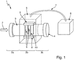
- a magnetic-inductive flowmeter 1 for measuring the flow of a flowing fluid 2 through a measuring tube 3 is shown.
- the measuring tube 3 is provided with an electrically insulating liner 4 in the area facing the fluid, ie on the inside over the entire length. It is convenient to divide the measuring tube 3 virtually into an inlet section 3a, a measuring section 3b to which the sensor unit is attached, and an outflow section 3c.
- a pair of measuring electrodes 8 for picking up the induced voltage and the magnet system 9, 9 ' which is represented by two cuboids for the sake of simplicity, are shown.
- the magnet system 9,9 ' comprises at least two coils 9,9' for generating the magnetic field 10 and possibly also pole pieces for realizing an advantageous spatial distribution and / or field plates.
- the connecting axes of the measuring electrode pair 8 and the field coils 9 each extend perpendicular to one another, wherein the two field coils and the two measuring electrodes 8 are respectively positioned on opposite sides of the measuring tube 3.
- the sensor unit with their respective components such. B, the measuring electrode pair 8 and the magnet system 9,9 ' is usually at least partially surrounded by a housing 5.
- an electronics unit 6 is further provided which is electrically connected via a connecting cable 7 to the field device 1.
- the electronics unit is used for signal acquisition and / or evaluation and the supply of the coils, as well as an interface to the environment, eg. B. the measured value output or setting the device.
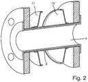
- the first steps of the inventive method for reducing the cross section of the measuring tube in the measuring section are in Fig. 2 shown.
- the measuring tube 3 has a circular cross-sectional area.
- a cold forming according to the invention is in Fig. 3 illustrated.
- the cold forming is carried out by means of two pressure pistons 12, 12 ', which are pressed in the region between the first 11 and second collar 11' from two opposite sides of the measuring tube 3 to the measuring tube.
- the first and second collars 11, 11 ' cause a stabilizing effect for the measuring tube 3 during this process.
- no welding studs are provided.
- the plunger 12,12 'in another embodiment may also have recesses for previously mounted weld studs.
- the respectively required components of the sensor unit of the flowmeter can be attached.
- the at least two measuring electrodes 8, 8 ' can be fastened and then the magnet system 9, 9'.
- a cold-formed measuring tube 3 'with mounted magnet system 9, 9' is shown, which are attached to two welding studs 13, 13 '. Further, a welded to the first and second collar 11,11 'housing 5 can be seen.
- the arrangement of a housing 5 directly on the first and second collar 11,11 ' is particularly easy to implement and requires no further design means.
- the first and second collar in principle has a dual function: a stabilization of the measuring tube 3 during cold forming and a receiving device for the housing. 5
Landscapes
- Physics & Mathematics (AREA)
- Fluid Mechanics (AREA)
- General Physics & Mathematics (AREA)
- Electromagnetism (AREA)
- Measuring Volume Flow (AREA)
Description
- Die Erfindung betrifft ein Verfahren zur Herstellung einer Vorrichtung zur Messung des Durchflusses eines strömenden Fluides durch ein Messrohr nach dem magnetisch-induktiven Messprinzip.
- Magnetisch-induktive Durchflussmessgeräte finden vielfach Anwendung in der Prozess- und Automatisierungstechnik für Fluide ab einer elektrischen Leitfähigkeit von etwa 5µS/cm. Entsprechende Durchflussmessgeräte werden von der Anmelderin in unterschiedlichsten Ausführungsformen für verschiedene Anwendungsbereiche beispielsweise unter der Bezeichnung PROMAG vertrieben.
- Das Messprinzip beruht auf dem Faraday'schen Gesetz der magnetischen Induktion und ist aus diversen Veröffentlichungen bekannt. Mittels eines an einem Messabschnitt befestigten Magnetsystems wird im Wesentlichen senkrecht zur Strömungsrichtung des leitfähigen Fluides ein Magnetfeld zeitlich konstanter Stärke erzeugt. Dadurch werden die im strömenden Fluid vorhandenen Ionen in entgegengesetzte Richtungen abgelenkt. Die durch diese Ladungstrennung entstehende elektrische Spannung wird mittels mindestens eines ebenfalls im Messrohrteilabschnitt befestigten Messelektrodenpaares abgegriffen. Die abgegriffene Spannung ist proportional zur Strömungsgeschwindigkeit des Fluides und damit proportional zum Volumendurchfluss.
- Die Messgenauigkeit eines magnetisch-induktiven Durchflussmessgeräts hängt dabei von vielen verschiedenen Faktoren ab. Manche davon betreffen die Konstruktion an sich, wie beispielsweise die Positioniergenauigkeit des Magnetsystems, oder die Auslesung des Messsignals über das mindestens eine Messelektrodenpaar sowie dessen Geometrie. Weiterhin weisen die Messperformance und Messgenauigkeit eine empfindliche Abhängigkeit vom vorherrschenden Strömungsprofil des Fluides auf.
- Das vorherrschende Strömungsprofil wiederum ist abhängig von der Reynoldszahl, welche von der Fließgeschwindigkeit, der Geometrie des Messrohres und dessen Oberflächenrauhigkeit im Inneren Bereich, von physikalischen und/oder chemischen Materialparametern des Fluides, wie beispielsweise der Viskosität, und von den Einlaufbedingungen des strömenden Fluides im Messrohr vor dem Messabschnitt, dem sogenannten Einlaufabschnitt, in welchem das Messgerät befestigt ist.
- Bei gegebener Durchflussmenge bzw. bei gegebenem Volumendurchfluss bestimmt sich die Fließgeschwindigkeit des Fluides aus der Querschnittsfläche des Messrohres. Für sehr geringe Fließgeschwindigkeiten liegt bei einem ausreichend langen geraden Einlaufabschnitt des Messrohres, an welchen sich der Messabschnitt anschließt, typischerweise ein laminares Strömungsprofil vor. Erhöht sich die Fließgeschwindigkeit bzw. die Reynoldszahl, gelangt man in einen Übergangsbereich, in welchem die Strömung anfällig wird für kleinste Störungen. In diesem Bereich ist eine vergleichsweise hohe Messwertabweichung zu beobachten. Erhöht man die Fließgeschwindigkeit weiter, so liegt ein zunehmend turbulentes Strömungsprofil vor, für welches die Messwertabweichung wieder vergleichbar ist mit derjenigen, welche für ein laminares Strömungsprofil vorherrscht. Sehr hohe Fließgeschwindigkeiten können allerdings nachteilig zum Auftreten von Kavitation führen.
- Eine Bestrebung, die Messgenauigkeit in Bezug auf die Abhängigkeit vom vorherrschenden Strömungsprofil zu verbessern, besteht in einer teilweisen Reduzierung der Querschnittsfläche des Messrohres im Bereich des Messabschnitts. Eine Reduzierung der Querschnittsfläche bietet den Vorteil, dass die Fließgeschwindigkeit des Fluides in diesem Bereich höher ist. Dadurch wird das vorherrschende Strömungsprofil konditioniert, was in einem großen Bereich für die Fließgeschwindigkeit zu einer Verbesserung der Messperformance bzw. Messempfindlichkeit führt. Dadurch können dann wiederum der Einlaufabschnitt und Ausströmabschnitt des Messrohres kürzer gewählt werden, was insbesondere in Bezug auf den Materialaufwand von Vorteil sein kann.
- Eine Konstruktion eines Messrohres mit teilweise reduzierter Querschnittsfläche ist beispielsweise in der
EP2600119A1 bekannt geworden. Dort ist ein magnetisch-induktives Durchflussmessgerät beschrieben, wobei die Querschnittsfläche des Messabschnitts sowohl kleiner ist als die Querschnittsfläche des Einströmabschnitts, als auch kleiner als die Querschnittsfläche des sich an den Messabschnitt anschließenden Ausströmabschnitts. Darüber hinaus wird für den Messabschnitt insbesondere ein rechteckiges Messrohrprofil gewählt. In Bezug auf die Herstellung eines solchen Messrohres ist beschrieben, dass die Querschnittsreduktion durch von außen auf das Messrohr einwirkende Kräfte erreicht wird. Wie die Querschnittsreduzierung jedoch im Detail umgesetzt wird und wie die Krafteinwirkung kontrolliert werden kann, derart dass durch die Krafteinwirkung eine bestimmte Form des Messrohres erreicht werden kann, ist nicht offenbart. Ferner ist nicht beschrieben, wie gewährleistet werden kann, dass ein im Inneren des Messrohres angeordneter Liner durch die Querschnittsreduzierung nicht beschädigt wird. - Eine weitere Methode zur Reduzierung der Querschnittsfläche des Messabschnitts besteht in der Anwendung einer Innenhochdruckumformung, dem sogenannten Hydroforming Verfahren und ist in der
DE102008057755A1 bekannt geworden. Jedoch besteht auch bei diesem Verfahren die Problematik in Bezug auf den Liner, der erst im Anschluss an die Umformung des Messrohres integriert werden kann. Dies ist aber wesentlich komplizierter, als die Integration eines Liners in ein Messrohr mit gleichbleibender Querschnittsfläche. - Der vorliegenden Erfindung liegt die Aufgabe zugrunde, ein Verfahren zur Herstellung einer Vorrichtung zur Messung des Durchflusses nach dem magnetisch-induktiven Messprinzip bereitzustellen, mit welchem die Querschnittsfläche im Messabschnitt einfach und zuverlässig reduziert werden kann.
- Diese Aufgabe wird erfindungsgemäß gelöst durch ein Verfahren zur Herstellung einer Vorrichtung zur Messung des Durchflusses eines strömenden Fluides durch ein Messrohr aus Metall nach dem magnetisch-induktiven Prinzip mit folgenden Verfahrensschritten
- ein erster und ein zweiter Kragen aus Metall werden vom äußeren Bereich am Messrohr mit einer Ausrichtung senkrecht zur Rohrachse des Messrohres befestigt,
- das Messrohr wird im inneren Bereich mit einem elektrisch nicht leitfähigen, elastischen Liner ausgekleidet,
- ein Messabschnitt des Messrohres, welcher sich zumindest teilweise zwischen dem ersten und dem zweiten Kragen befindet, wird mittels einer Kaltumformung derart verändert, dass die Querschnittsfläche des Messabschnittes gegenüber den Querschnittsflächen eines sich vor dem Messabschnitt befindenden Einströmabschnitts des Messrohres und eines sich an den Messabschnitt anschließenden Ausströmabschnitts des Messrohres reduziert wird.
- Durch die Kaltumformung kann die Querschnittsfläche des Messrohres im Bereich des Messabschnitts gezielt reduziert werden. Da die Temperaturen während einer Kaltumformung unterhalb der Rekristallisationstemperatur des jeweiligen Materials bleibt, ist dieses Verfahren im Vergleich zu den in der Beschreibungseinleitung genannten schonender. Es kommt beispielsweise typischerweise nicht zum Verzundern einzelner Bereiche. Weiterhin erlaubt die Methode enge Maßtoleranzen für die Umformung, bei welcher sich außerdem die Festigkeit bzw. Duktilität des Werkstoffes erhöht.
- Vorteilhaft lässt sich das Verfahren mit geringen Investitionskosten und auf einfache Weise realisieren. Das Anbringen des ersten und zweiten Kragens hat eine zusätzliche stabilisierende Wirkung für den Umformprozess. Ein weiterer Vorteil des erfindungsgemäßen Verfahrens betrifft den Liner. Dieser kann bereits vor der Umformung in das Messrohr eingebracht werden. Dies erleichtert den Herstellungsprozess ungemein, denn eine passgenaue Integrierung eines Liners in ein Messrohr mit variabler Querschnittsfläche ist deutlich aufwendiger.
- In einer vorteilhaften Ausgestaltung befindet sich sich der erste Kragen im Bereich des Übergangs zwischen dem Einströmabschnitt und Messabschnitt t und der zweite Kragen im Bereich des Übergangs zwischen dem Messabschnitt und dem Ausströmabschnitt.
- Alternativ befindet sich der erste Kragen im Bereich des Einströmabschnittes und der zweite Kragen im Bereich des Ausströmabschnitts. Außerdem sieht eine Ausgestaltung vor, dass sich der erste und der zweite Kragen im Bereich des Messabschnitts befinden.
- Die genaue Ausgestaltung und Anordnung des ersten und zweiten Kragens am Messrohr kann dabei auf die jeweilige Anwendung angepasst werden. Ist aus Platzgründen eine besonders kompakte Konstruktion erwünscht, empfiehlt sich eine Anbringung des ersten und zweiten Kragens im Bereich des Messabschnitts. Ansonsten ist in der Regel die Nennweite des Messrohres entscheidend für die Positionierung des ersten und zweiten Kragens. Es versteht sich ferner von selbst, dass neben den hier genannten Anordnungen noch weitere Möglichkeiten für die genaue Positionierung vorhanden sind, welche ebenfalls unter die Erfindung fallen.
- Es ist von Vorteil, wenn am ersten und am zweiten Kragen ein Gehäuse für das Durchflussmessgerät befestigt wird. Durch diese Maßnahme werden keinerlei weitere Konstruktionen am Messrohr oder Bauteil benötigt, um das Gehäuse des Durchflussmessgeräts zu befestigen. Dem ersten und zweiten Kragen kommt somit zudem eine Doppelfunktionalität zu - die stabilisierende Wirkung während der Umformung sowie die einer Befestigungskomponente für das Gehäuse.
- Es ist außerdem von Vorteil, wenn ein Messrohr mit kreisrundem oder rechteckigem Querschnitt verwendet wird.
- In einer bevorzugten Ausgestaltung weist der Messabschnitt nach der Kaltumformung eine veränderte Querschnittsflächengeometrie, insbesondere ein Rechteckprofil, auf. Es wird also nicht nur die Querschnittsfläche reduziert, sondern auch eine Änderung ihrer Geometrie vorgenommen.
- In einer besonders bevorzugten Ausgestaltung wird die Kaltumformung mittels zumindest zwei Druckstempeln vermittelt, welche vom äußeren Bereich des Messrohres zwischen dem ersten und dem zweiten Kragen von zwei sich gegenüberliegenden Seiten an das Messrohr gepresst werden. Die Krägen stützen sich dann während der Umformung auf die Druckstempel und bewirken entsprechend eine Stabilisierung.
- Es ist weiterhin von Vorteil, wenn auf zumindest zwei gegenüberliegenden Seiten des Messrohres vom äußeren Bereich jeweils zumindest ein Schweißbolzen befestigt wird, welcher mittig entlang einer zur Rohrachse parallelen Verbindunglinie durch den ersten und zweiten Kragen positioniert wird. Dabei ist es insbesondere von Vorteil, wenn das Magnetsystem an den zumindest zwei Schweißbolzen befestigt wird. Ebenfalls ist es von Vorteil, wenn die Schweißbolzen vor der Kaltumformung am Messrohr befestigt werden, und wenn für die Kaltumformung zumindest zwei Druckstempel verwendet werden, welche Druckstempel Aussparungen für die Schweißbolzen aufweisen.
- In einer weiteren Ausgestaltung werden nach der Kaltumformung zumindest zwei Messelektroden im oder am Messrohr befestigt.
- In einer besonders bevorzugten Ausgestaltung wird ein Liner mit einer Härte weniger als Shore 90A verwendet. Durch die Verwendung eines solchen Liners kann gewährleistet werden, dass der Liner während der Kaltumformung nicht beschädigt wird, da er eine ausreichende Elastizität aufweist.
- Es ist dabei von Vorteil, wenn ein Liner aus Polyurethan, Weichgummi, Hartgummi oder PTFE verwendet wird.
- In einer bevorzugten Ausgestaltung werden der erste und zweite Kragen geschweißt und die Schweißbolzen durch Punktschweißen am Messrohr befestigt.
- In einer weiteren bevorzugten Ausgestaltung wird die Querschnittsfläche des Messabschnittes gegenüber der Querschnittsflächen des Einströmabschnitts und Ausströmabschnitts um den Faktor 1,1 bis 1,5 reduziert.
- Die Erfindung sowie ihre vorteilhaften Ausgestaltungen werden im Folgenden anhand der Figuren
Fig. 1 bis Fig.3 beschrieben. Es zeigt: -
Fig. 1 : ein magnetisch-induktives Durchflussmessgerät gemäß dem Stand der Technik, -
Fig. 2 : ein mit einem Liner ausgekleidetes Messrohr, an welchem ein erster und ein zweiter Kragen befestigt sind, -
Fig. 3 : eine Illustrierung einer Kaltumformung mittels zweier Druckstempel an einem Messrohr wie inFig. 2 dargestellt. -
Fig. 4 : ein kaltumformtes Messrohr mit montiertem Magnetsystem. - In
Fig. 1 ist ein magnetisch-induktives Durchflussmessgerät 1 zur Messung des Durchflusses eines strömenden Fluides 2 durch ein Messrohr 3 gezeigt. Das Messrohr 3 ist im dem Fluid zugewandten Bereich, d. h. an der Innenseite über die ganze Länge, mit einem elektrisch isolierenden Liner 4 versehen. Es ist zweckdienlich, das Messrohr 3 virtuell in einen Einlaufabschnitt 3a, einen Messabschnitt 3b, an welchem die Sensoreinheit angebracht ist, und einen Ausströmabschnitt 3c zu unterteilen. Für die Sensoreinheit sind ein Messelektrodenpaar 8 zum Abgreifen der induzierten Spannung sowie das Magnetsystem 9,9', welches der Einfachheit halber durch zwei Quader dargestellt ist, gezeigt. Das Magnetsystem 9,9' umfasst zumindest zwei Spulen 9,9' zur Erzeugung des Magnetfeldes 10 und gegebenenfalls auch Polschuhe zur Realisierung einer vorteilhaften räumlichen Verteilung und/oder Feldbleche. Die Verbindungsachsen des Messelektrodenpaares 8 und der Feldspulen 9 verlaufen jeweils senkrecht zueinander, wobei die beiden Feldspulen und die beiden Messelektroden 8 jeweils auf gegenüberliegenden Seiten des Messrohres 3 positioniert sind. - Die Sensoreinheit mit ihren jeweiligen Komponenten wie z. B, dem Messelektrodenpaar 8 und dem Magnetsystem 9,9' ist üblicherweise zumindest teilweise von einem Gehäuse 5 umgeben. Im Gehäuse 5 oder im vorliegenden Falle außerhalb des Gehäuses 5 ist weiterhin eine Elektronikeinheit 6 vorgesehen welche über ein Verbindungskabel 7 mit dem Feldgerät 1 elektrisch verbunden ist. Die Elektronikeinheit dient der Signalerfassung und/oder -auswertung und der Speisung der Spulen, sowie als Schnittstelle zur Umgebung, z. B. der Messwertausgabe oder Einstellung des Geräts.
- Die ersten Schritte des erfindungsgemäßen Verfahrens zur Reduzierung des Querschnitts des Messrohres im Messabschnitt sind in
Fig. 2 gezeigt. Zuerst werden ein erster Kragen 11 und ein zweiter Kragen 11' vom äußeren Bereich am Messrohr 3 befestigt. Anschließend wird das Messrohr 3 im inneren Bereich mit einem elektrisch nicht leitfähigen Liner 4 ausgekleidet. In diesem Beispiel weist das Messrohr 3 eine kreisrunde Querschnittsfläche auf. - Die Durchführung einer erfindungsgemäßen Kaltumformung ist in
Fig. 3 illustriert. Die Kaltumformung wird mittels zweier Druckstempel 12, 12' vorgenommen, welche im Bereich zwischen dem ersten 11 und zweiten Kragen 11' von zwei gegenüberliegenden Seiten des Messrohres 3 an das Messrohr gepresst werden. Der erste und zweite Kragen 11,11' bewirken während dieses Vorgangs eine stabilisierende Wirkung für das Messrohr 3. In diesem Beispiel sind keine Schweißbolzen vorgesehen. Es versteht sich jedoch von selbst, dass die Druckstempel 12,12' in einem anderen Ausführungsbeispiel auch Aussparungen für zuvor angebrachte Schweißbolzen aufweisen können. - Nach der Umformung können die jeweils benötigten Komponenten der Sensoreinheit des Durchflussmessgeräts angebracht werden. Zuerst können beispielsweise die zumindest zwei Messelektroden 8,8' befestigt werden und anschließend das Magnetsystem 9,9'.
- In
Fig. 4 ist schließlich ein kaltumformtes Messrohr 3' mit montiertem Magnetsystem 9,9' gezeigt, welche an zwei Schweißbolzen 13,13' angebracht sind. Ferner ist ein an den ersten und zweiten Kragen 11,11' geschweißtes Gehäuse 5 zu sehen. Die Anordnung eines Gehäuses 5 direkt am ersten und zweiten Kragen 11,11' ist besonders einfach umzusetzen und bedarf keiner weiteren konstruktiven Mittel. Damit kommt dem ersten und zweiten Kragen im Prinzip eine Doppelfunktion zu: eine Stabilisierung des Messrohres 3 während der Kaltumformung und eine Aufnahmevorrichtung für das Gehäuse 5. -
- 1
- magnetisch induktives Durchflussmessgerät gemäß Stand der Technik
- 2
- strömendes Fluid
- 3
- Messrohr
- 4
- elektrisch isolierende Auskleidung, Liner
- 5
- Gehäuseeinheit oder Gehäuse
- 6
- Elektronikeinheit
- 7
- Verbindungskabel
- 8,8'
- Messelektroden
- 9,9'
- Magnetsystem mit zumindest zwei Spulen
- 10
- Magnetfeld senkrecht zur Strömungsrichtung des Fluides und zur Verbindungsachse durch die Messelektroden
- 11,11'
- erster und zweiter Kragen
- 12,12'
- Druckstempel
- 13,13'
- Schweißbolzen
Claims (16)
- Verfahren zur Herstellung einer Vorrichtung (1) zur Messung des Durchflusses eines strömenden Fluides durch ein Messrohr (3) aus Metall nach dem magnetisch-induktiven Prinzip mit folgenden Verfahrensschritten- Ein erster und ein zweiter Kragen (11,11') aus Metall werden vom äußeren Bereich am Messrohr (3) mit einer Ausrichtung senkrecht zur Rohrachse des Messrohres (3) befestigt,- das Messrohr (3) wird im inneren Bereich mit einem elektrisch nicht leitfähigen, elastischen Liner (4) ausgekleidet,- ein Messabschnitt (3b) des Messrohres (3), welcher sich zumindest teilweise zwischen dem ersten (11) und dem zweiten Kragen (11') befindet, wird mittels einer Kaltumformung derart verändert, dass die Querschnittsfläche des Messabschnittes (3b) gegenüber den Querschnittsflächen eines sich vor dem Messabschnitt befindenden Einströmabschnitts (3a) des Messrohres (3) und eines sich an den Messabschnitt (3b) anschließenden Ausströmabschnitts (3c) des Messrohres (3) reduziert wird.
- Verfahren nach Anspruch 1,
wobei sich der erste Kragen (11) im Bereich des Übergangs zwischen dem Einströmabschnitt (3a) und Messabschnitt (3b) befindet und der zweite Kragen (11') im Bereich des Übergangs zwischen dem Messabschnitt (3b) und dem Ausströmabschnitt (3c). - Verfahren nach Anspruch 1,
wobei sich der erste Kragen (11) im Bereich des Einströmabschnittes (3a) befindet und der zweite Kragen (11') im Bereich des Ausströmabschnitts (3c). - Verfahren nach Anspruch 1,
wobei sich der erste (11) und der zweite Kragen (11') im Bereich des Messabschnitts (3b) befinden. - Verfahren nach zumindest einem der vorhergehenden Ansprüche,
wobei am ersten (11) und am zweiten Kragen (11') ein Gehäuse (5) befestigt wird. - Verfahren nach einem der vorhergehenden Ansprüche,
wobei ein Messrohr (3) mit kreisrundem oder rechteckigem Querschnitt verwendet wird. - Verfahren nach zumindest einem der vorhergehenden Ansprüche, wobei der Messabschnitt (3b) nach der Kaltumformung eine veränderte Querschnittsflächengeometrie, insbesondere ein Rechteckprofil, aufweist.
- Verfahren nach zumindest einem der vorhergehenden Ansprüche, wobei die Kaltumformung mittels zumindest zwei Druckstempeln (12,12') vermittelt wird, welche vom äußeren Bereich des Messrohres (3) zwischen dem ersten (11) und dem zweiten Kragen (11') von zwei sich gegenüberliegenden Seiten an das Messrohr gepresst werden.
- Verfahren nach zumindest einem der vorhergehenden Ansprüche, wobei auf zumindest zwei gegenüberliegenden Seiten des Messrohres (3) vom äußeren Bereich jeweils zumindest ein Schweißbolzen (13,13') befestigt wird, welcher mittig entlang einer zur Rohrachse parallelen Verbindunglinie durch den ersten (11) und zweiten Kragen (11') positioniert wird.
- Verfahren nach Anspruch 9,
wobei das Magnetsystem (9,9') an den Schweißbolzen (13,13') befestigt wird. - Verfahren nach zumindest einem der Ansprüche 9 oder 10,
wobei die Schweißbolzen (13,13') vor der Kaltumformung am Messrohr (3) befestigt werden, und wobei für die Kaltumformung zumindest zwei Drucktempel (12,12') verwendet werden, welche Druckstempel (12,12') Aussparungen für die Schweißbolzen (13,13') aufweisen. - Verfahren nach einem der vorhergehenden Ansprüche,
wobei nach der Kaltumformung zumindest zwei Messelektroden (8,8') im oder am Messrohr (3) befestigt werden. - Verfahren nach zumindest einem der vorhergehenden Ansprüche, wobei ein Liner (4) mit einer Härte weniger als Shore 90A verwendet wird.
- Verfahren nach Anspruch 13,
wobei ein Liner (4) aus Polyurethan, Weichgummi, Hartgummi oder PTFE verwendet wird. - Verfahren nach zumindest einem der vorhergehenden Ansprüche, wobei der erste (11) und zweite Kragen (11') geschweißt werden und die Schweißbolzen (13,13') durch Punktschweißen am Messrohr (3) befestigt werden.
- Verfahren nach zumindest einem der vorhergehenden Ansprüche, wobei die Querschnittsfläche des Messabschnittes (3b) gegenüber der Querschnittsflächen des Einströmabschnitts (3a) und Ausströmabschnitts (3c) um den Faktor 1,1 bis 1,5 reduziert wird.
Applications Claiming Priority (2)
| Application Number | Priority Date | Filing Date | Title |
|---|---|---|---|
| DE102014113408.7A DE102014113408A1 (de) | 2014-09-17 | 2014-09-17 | Verfahren zur Herstellung eines Magnetisch-induktives Durchfluss- messgeräts mit zum Teil reduziertem Querschnitt |
| PCT/EP2015/069053 WO2016041724A1 (de) | 2014-09-17 | 2015-08-19 | Verfahren zur herstellung eines magnetisch-induktives durchflussmessgeräts mit zum teil reduziertem querschnitt |
Publications (2)
| Publication Number | Publication Date |
|---|---|
| EP3194900A1 EP3194900A1 (de) | 2017-07-26 |
| EP3194900B1 true EP3194900B1 (de) | 2018-10-31 |
Family
ID=53879521
Family Applications (1)
| Application Number | Title | Priority Date | Filing Date |
|---|---|---|---|
| EP15751020.7A Active EP3194900B1 (de) | 2014-09-17 | 2015-08-19 | Verfahren zur herstellung eines magnetisch-induktiven durchflussmessgeräts mit zum teil reduziertem querschnitt |
Country Status (4)
| Country | Link |
|---|---|
| US (1) | US10551228B2 (de) |
| EP (1) | EP3194900B1 (de) |
| DE (1) | DE102014113408A1 (de) |
| WO (1) | WO2016041724A1 (de) |
Families Citing this family (11)
| Publication number | Priority date | Publication date | Assignee | Title |
|---|---|---|---|---|
| US20150315666A1 (en) * | 2014-04-30 | 2015-11-05 | Ford Global Technologies, Llc | Induction annealing as a method for expanded hydroformed tube formability |
| DE102014113408A1 (de) | 2014-09-17 | 2016-03-17 | Endress + Hauser Flowtec Ag | Verfahren zur Herstellung eines Magnetisch-induktives Durchfluss- messgeräts mit zum Teil reduziertem Querschnitt |
| DE102018108197B4 (de) | 2018-04-06 | 2024-11-28 | Endress+Hauser Flowtec Ag | Magnetisch-induktives Durchflussmessgerät und Messstelle mit einem solchen |
| DE102018131167A1 (de) | 2018-12-06 | 2020-06-10 | Endress+Hauser Flowtec Ag | Magnetisch-induktives Durchflussmessgerät |
| DE102018132935A1 (de) | 2018-12-19 | 2020-06-25 | Endress+Hauser Flowtec Ag | Magnetisch-induktives Durchflussmessgerät und Messstelle |
| DE102019108985A1 (de) | 2019-04-05 | 2020-10-08 | Endress+Hauser Flowtec Ag | Magnetisch-induktives Durchflussmessgerät |
| DE102019123413A1 (de) | 2019-09-02 | 2021-03-04 | Endress+Hauser Flowtec Ag | Magnetisch-induktives Durchflussmessgerät |
| DE102020111126A1 (de) | 2020-04-23 | 2021-10-28 | Endress+Hauser Flowtec Ag | Messrohr, Verfahren zur Herstellung eines Messrohres und magnetisch-induktives Durchflussmessgerät |
| DE102023120595A1 (de) | 2023-08-03 | 2025-02-06 | Endress + Hauser Flowtec Ag | Magnetisch-induktives Durchflussmessgerät und Verfahren zum Auslegen eines magnetisch-induktiven Durchflussmessgerätes |
| WO2025026986A1 (de) | 2023-08-03 | 2025-02-06 | Endress+Hauser Flowtec Ag | Magnetisch-induktives durchflussmessgerät und verfahren zum auslegen eines magnetisch-induktiven durchflussmessgerätes |
| DE102023135864A1 (de) * | 2023-12-19 | 2025-06-26 | Endress+Hauser Flowtec Ag | Durchflussmessgerät |
Family Cites Families (15)
| Publication number | Priority date | Publication date | Assignee | Title |
|---|---|---|---|---|
| US2733604A (en) * | 1956-02-07 | coulter | ||
| US3406569A (en) * | 1965-07-07 | 1968-10-22 | Fischer & Porter Co | Magnetic flowmeter of improved linearity |
| JP3043087B2 (ja) * | 1991-03-25 | 2000-05-22 | 愛知時計電機株式会社 | 残留磁気式電磁流量計 |
| US6983661B2 (en) * | 2003-05-15 | 2006-01-10 | Endress + Hauser Flowtec Ag | Electromagnetic flow sensor |
| DE102006054008B4 (de) * | 2006-11-16 | 2013-11-28 | Abb Ag | Magnetisch-induktiver Durchflussmesser mit einem mit Losflanschen ausgestattetem Messrohr |
| DE102008057756A1 (de) | 2008-11-17 | 2010-05-27 | Krohne Ag | Magnetisch-induktives Durchflußmeßgerät |
| DE102008057755B4 (de) | 2008-11-17 | 2015-12-17 | Krohne Ag | Magnetisch-induktives Durchflußmeßgerät |
| DE102008059067A1 (de) * | 2008-11-26 | 2010-06-02 | Krohne Ag | Magnetisch-induktives Durchflußmeßgerät |
| DE102008054961A1 (de) | 2008-12-19 | 2010-07-01 | Endress + Hauser Flowtec Ag | Durchfluss-Messgerät und Verfahren zur Herstellung eines Messrohrs eines Durchfluss-Messgerätes |
| CN103124558B (zh) | 2010-08-23 | 2015-06-24 | 电气化学工业株式会社 | 交联透明质酸组合物和自交联透明质酸颗粒 |
| DE102011104799B4 (de) | 2011-06-06 | 2013-04-25 | Krohne Messtechnik Gmbh | Magnetisch-induktives Durchflussmessgerät und Verfahren zu dessen Betreiben |
| DE102011119982A1 (de) * | 2011-12-02 | 2013-06-06 | Krohne Ag | Magnetisch-induktives Durchflussmessgerät |
| DE102012017904A1 (de) * | 2012-08-21 | 2014-03-20 | Krohne Ag | Magnetisch-induktives Durchflussmessgerät und Verfahren zu seiner Herstellung |
| CN102840357B (zh) | 2012-08-23 | 2013-11-13 | 杭州云谷科技有限公司 | 流量测量和控制一体化装置 |
| DE102014113408A1 (de) | 2014-09-17 | 2016-03-17 | Endress + Hauser Flowtec Ag | Verfahren zur Herstellung eines Magnetisch-induktives Durchfluss- messgeräts mit zum Teil reduziertem Querschnitt |
-
2014
- 2014-09-17 DE DE102014113408.7A patent/DE102014113408A1/de not_active Withdrawn
-
2015
- 2015-08-19 US US15/510,853 patent/US10551228B2/en active Active
- 2015-08-19 WO PCT/EP2015/069053 patent/WO2016041724A1/de not_active Ceased
- 2015-08-19 EP EP15751020.7A patent/EP3194900B1/de active Active
Non-Patent Citations (1)
| Title |
|---|
| None * |
Also Published As
| Publication number | Publication date |
|---|---|
| CN106796131A (zh) | 2017-05-31 |
| DE102014113408A1 (de) | 2016-03-17 |
| EP3194900A1 (de) | 2017-07-26 |
| US20170261356A1 (en) | 2017-09-14 |
| US10551228B2 (en) | 2020-02-04 |
| WO2016041724A1 (de) | 2016-03-24 |
Similar Documents
| Publication | Publication Date | Title |
|---|---|---|
| WO2016041724A1 (de) | Verfahren zur herstellung eines magnetisch-induktives durchflussmessgeräts mit zum teil reduziertem querschnitt | |
| EP2044392B1 (de) | MESSSYSTEM FÜR EIN IN EINER PROZEßLEITUNG STRÖMENDES MEDIUM | |
| EP2187180B1 (de) | Magnetisch-induktives Durchflussmessgerät | |
| EP2227677B1 (de) | MEßSYSTEM FÜR EIN IN EINER PROZESSLEITUNG STRÖMENDES MEDIUM | |
| DE102014111047B4 (de) | Magnetisch-induktives Durchflussmessgerät mit mehreren Messelektrodenpaaren und unterschiedlichen Messrohrquerschnitten und Verfahren zur Messung des Durchflusses | |
| EP2700912B1 (de) | Magnetisch-induktives Durchflussmessgerät und Verfahren zu seiner Herstellung | |
| DE102014113404A1 (de) | Magnetisch-induktives Durchflussmessgerät mit einem Vierspulen- Magnetsystem | |
| EP3899439B1 (de) | Verfahren zur auslegung eines magnetisch-induktiven durchflussmessgerätes | |
| DE102011119982A1 (de) | Magnetisch-induktives Durchflussmessgerät | |
| EP2687827B1 (de) | Magnetisch-induktives Durchflussmessgerät | |
| DE102006034296A1 (de) | Meßsystem für ein in einer Prozeßleitung strömendes Medium | |
| EP3891475B1 (de) | Magnetisch-induktives durchflussmessgerät | |
| AT521356B1 (de) | Druckdifferenzaufnehmer für ein Durchflussmessgerät sowie Durchflussmessgerät | |
| WO2016041725A1 (de) | Magnetisch-induktives durchflussmessgerät mit einem magnetsystem mit mindestens vier spulen | |
| EP4025880B1 (de) | Magnetisch-induktives durchflussmessgerät | |
| DE102014113406A1 (de) | Magnetisch-induktives Durchflussmessgerät mit Einschub | |
| DE102016120303B4 (de) | Magnetisch-induktives Durchflussmessgerät zur Detektion von Fremdkörpern in einem ein Messrohr durchströmendes Medium | |
| DE102014105645B4 (de) | Durchflussmessgerät für strömende Fluide | |
| DE102006047815A1 (de) | Meßsystem für ein in einer Prozeßleitung strömendes Medium | |
| DE102019108985A1 (de) | Magnetisch-induktives Durchflussmessgerät | |
| EP3045875B1 (de) | Magnetisch-induktives durchflussmessgerät | |
| EP4562374A1 (de) | Magnetisch-induktives durchflussmessgerät | |
| EP3058318A1 (de) | Messrohr für magnetisch-induktive durchflussmesssysteme | |
| EP3045874A2 (de) | Magnetisch-induktives durchflussmessgerät | |
| DE102019123409A1 (de) | Magnetisch-induktives Durchflussmessgerät |
Legal Events
| Date | Code | Title | Description |
|---|---|---|---|
| STAA | Information on the status of an ep patent application or granted ep patent |
Free format text: STATUS: THE INTERNATIONAL PUBLICATION HAS BEEN MADE |
|
| PUAI | Public reference made under article 153(3) epc to a published international application that has entered the european phase |
Free format text: ORIGINAL CODE: 0009012 |
|
| STAA | Information on the status of an ep patent application or granted ep patent |
Free format text: STATUS: REQUEST FOR EXAMINATION WAS MADE |
|
| 17P | Request for examination filed |
Effective date: 20170213 |
|
| AK | Designated contracting states |
Kind code of ref document: A1 Designated state(s): AL AT BE BG CH CY CZ DE DK EE ES FI FR GB GR HR HU IE IS IT LI LT LU LV MC MK MT NL NO PL PT RO RS SE SI SK SM TR |
|
| AX | Request for extension of the european patent |
Extension state: BA ME |
|
| DAV | Request for validation of the european patent (deleted) | ||
| DAX | Request for extension of the european patent (deleted) | ||
| GRAP | Despatch of communication of intention to grant a patent |
Free format text: ORIGINAL CODE: EPIDOSNIGR1 |
|
| STAA | Information on the status of an ep patent application or granted ep patent |
Free format text: STATUS: GRANT OF PATENT IS INTENDED |
|
| RIC1 | Information provided on ipc code assigned before grant |
Ipc: G01F 15/14 20060101ALI20180530BHEP Ipc: G01F 1/58 20060101AFI20180530BHEP |
|
| INTG | Intention to grant announced |
Effective date: 20180612 |
|
| GRAS | Grant fee paid |
Free format text: ORIGINAL CODE: EPIDOSNIGR3 |
|
| GRAA | (expected) grant |
Free format text: ORIGINAL CODE: 0009210 |
|
| STAA | Information on the status of an ep patent application or granted ep patent |
Free format text: STATUS: THE PATENT HAS BEEN GRANTED |
|
| AK | Designated contracting states |
Kind code of ref document: B1 Designated state(s): AL AT BE BG CH CY CZ DE DK EE ES FI FR GB GR HR HU IE IS IT LI LT LU LV MC MK MT NL NO PL PT RO RS SE SI SK SM TR |
|
| REG | Reference to a national code |
Ref country code: GB Ref legal event code: FG4D Free format text: NOT ENGLISH Ref country code: CH Ref legal event code: EP |
|
| REG | Reference to a national code |
Ref country code: AT Ref legal event code: REF Ref document number: 1059942 Country of ref document: AT Kind code of ref document: T Effective date: 20181115 |
|
| REG | Reference to a national code |
Ref country code: DE Ref legal event code: R096 Ref document number: 502015006690 Country of ref document: DE |
|
| REG | Reference to a national code |
Ref country code: IE Ref legal event code: FG4D Free format text: LANGUAGE OF EP DOCUMENT: GERMAN |
|
| REG | Reference to a national code |
Ref country code: NL Ref legal event code: FP |
|
| REG | Reference to a national code |
Ref country code: LT Ref legal event code: MG4D |
|
| PG25 | Lapsed in a contracting state [announced via postgrant information from national office to epo] |
Ref country code: NO Free format text: LAPSE BECAUSE OF FAILURE TO SUBMIT A TRANSLATION OF THE DESCRIPTION OR TO PAY THE FEE WITHIN THE PRESCRIBED TIME-LIMIT Effective date: 20190131 Ref country code: PL Free format text: LAPSE BECAUSE OF FAILURE TO SUBMIT A TRANSLATION OF THE DESCRIPTION OR TO PAY THE FEE WITHIN THE PRESCRIBED TIME-LIMIT Effective date: 20181031 Ref country code: LT Free format text: LAPSE BECAUSE OF FAILURE TO SUBMIT A TRANSLATION OF THE DESCRIPTION OR TO PAY THE FEE WITHIN THE PRESCRIBED TIME-LIMIT Effective date: 20181031 Ref country code: FI Free format text: LAPSE BECAUSE OF FAILURE TO SUBMIT A TRANSLATION OF THE DESCRIPTION OR TO PAY THE FEE WITHIN THE PRESCRIBED TIME-LIMIT Effective date: 20181031 Ref country code: BG Free format text: LAPSE BECAUSE OF FAILURE TO SUBMIT A TRANSLATION OF THE DESCRIPTION OR TO PAY THE FEE WITHIN THE PRESCRIBED TIME-LIMIT Effective date: 20190131 Ref country code: LV Free format text: LAPSE BECAUSE OF FAILURE TO SUBMIT A TRANSLATION OF THE DESCRIPTION OR TO PAY THE FEE WITHIN THE PRESCRIBED TIME-LIMIT Effective date: 20181031 Ref country code: HR Free format text: LAPSE BECAUSE OF FAILURE TO SUBMIT A TRANSLATION OF THE DESCRIPTION OR TO PAY THE FEE WITHIN THE PRESCRIBED TIME-LIMIT Effective date: 20181031 Ref country code: ES Free format text: LAPSE BECAUSE OF FAILURE TO SUBMIT A TRANSLATION OF THE DESCRIPTION OR TO PAY THE FEE WITHIN THE PRESCRIBED TIME-LIMIT Effective date: 20181031 Ref country code: IS Free format text: LAPSE BECAUSE OF FAILURE TO SUBMIT A TRANSLATION OF THE DESCRIPTION OR TO PAY THE FEE WITHIN THE PRESCRIBED TIME-LIMIT Effective date: 20190228 |
|
| PG25 | Lapsed in a contracting state [announced via postgrant information from national office to epo] |
Ref country code: AL Free format text: LAPSE BECAUSE OF FAILURE TO SUBMIT A TRANSLATION OF THE DESCRIPTION OR TO PAY THE FEE WITHIN THE PRESCRIBED TIME-LIMIT Effective date: 20181031 Ref country code: PT Free format text: LAPSE BECAUSE OF FAILURE TO SUBMIT A TRANSLATION OF THE DESCRIPTION OR TO PAY THE FEE WITHIN THE PRESCRIBED TIME-LIMIT Effective date: 20190301 Ref country code: RS Free format text: LAPSE BECAUSE OF FAILURE TO SUBMIT A TRANSLATION OF THE DESCRIPTION OR TO PAY THE FEE WITHIN THE PRESCRIBED TIME-LIMIT Effective date: 20181031 Ref country code: GR Free format text: LAPSE BECAUSE OF FAILURE TO SUBMIT A TRANSLATION OF THE DESCRIPTION OR TO PAY THE FEE WITHIN THE PRESCRIBED TIME-LIMIT Effective date: 20190201 Ref country code: SE Free format text: LAPSE BECAUSE OF FAILURE TO SUBMIT A TRANSLATION OF THE DESCRIPTION OR TO PAY THE FEE WITHIN THE PRESCRIBED TIME-LIMIT Effective date: 20181031 |
|
| PG25 | Lapsed in a contracting state [announced via postgrant information from national office to epo] |
Ref country code: DK Free format text: LAPSE BECAUSE OF FAILURE TO SUBMIT A TRANSLATION OF THE DESCRIPTION OR TO PAY THE FEE WITHIN THE PRESCRIBED TIME-LIMIT Effective date: 20181031 Ref country code: CZ Free format text: LAPSE BECAUSE OF FAILURE TO SUBMIT A TRANSLATION OF THE DESCRIPTION OR TO PAY THE FEE WITHIN THE PRESCRIBED TIME-LIMIT Effective date: 20181031 |
|
| REG | Reference to a national code |
Ref country code: DE Ref legal event code: R097 Ref document number: 502015006690 Country of ref document: DE |
|
| PG25 | Lapsed in a contracting state [announced via postgrant information from national office to epo] |
Ref country code: RO Free format text: LAPSE BECAUSE OF FAILURE TO SUBMIT A TRANSLATION OF THE DESCRIPTION OR TO PAY THE FEE WITHIN THE PRESCRIBED TIME-LIMIT Effective date: 20181031 Ref country code: EE Free format text: LAPSE BECAUSE OF FAILURE TO SUBMIT A TRANSLATION OF THE DESCRIPTION OR TO PAY THE FEE WITHIN THE PRESCRIBED TIME-LIMIT Effective date: 20181031 Ref country code: SK Free format text: LAPSE BECAUSE OF FAILURE TO SUBMIT A TRANSLATION OF THE DESCRIPTION OR TO PAY THE FEE WITHIN THE PRESCRIBED TIME-LIMIT Effective date: 20181031 Ref country code: SM Free format text: LAPSE BECAUSE OF FAILURE TO SUBMIT A TRANSLATION OF THE DESCRIPTION OR TO PAY THE FEE WITHIN THE PRESCRIBED TIME-LIMIT Effective date: 20181031 |
|
| PLBE | No opposition filed within time limit |
Free format text: ORIGINAL CODE: 0009261 |
|
| STAA | Information on the status of an ep patent application or granted ep patent |
Free format text: STATUS: NO OPPOSITION FILED WITHIN TIME LIMIT |
|
| 26N | No opposition filed |
Effective date: 20190801 |
|
| PG25 | Lapsed in a contracting state [announced via postgrant information from national office to epo] |
Ref country code: SI Free format text: LAPSE BECAUSE OF FAILURE TO SUBMIT A TRANSLATION OF THE DESCRIPTION OR TO PAY THE FEE WITHIN THE PRESCRIBED TIME-LIMIT Effective date: 20181031 |
|
| PG25 | Lapsed in a contracting state [announced via postgrant information from national office to epo] |
Ref country code: TR Free format text: LAPSE BECAUSE OF FAILURE TO SUBMIT A TRANSLATION OF THE DESCRIPTION OR TO PAY THE FEE WITHIN THE PRESCRIBED TIME-LIMIT Effective date: 20181031 |
|
| PG25 | Lapsed in a contracting state [announced via postgrant information from national office to epo] |
Ref country code: CH Free format text: LAPSE BECAUSE OF NON-PAYMENT OF DUE FEES Effective date: 20190831 Ref country code: MC Free format text: LAPSE BECAUSE OF FAILURE TO SUBMIT A TRANSLATION OF THE DESCRIPTION OR TO PAY THE FEE WITHIN THE PRESCRIBED TIME-LIMIT Effective date: 20181031 Ref country code: LI Free format text: LAPSE BECAUSE OF NON-PAYMENT OF DUE FEES Effective date: 20190831 Ref country code: LU Free format text: LAPSE BECAUSE OF NON-PAYMENT OF DUE FEES Effective date: 20190819 |
|
| REG | Reference to a national code |
Ref country code: BE Ref legal event code: MM Effective date: 20190831 |
|
| PG25 | Lapsed in a contracting state [announced via postgrant information from national office to epo] |
Ref country code: IE Free format text: LAPSE BECAUSE OF NON-PAYMENT OF DUE FEES Effective date: 20190819 |
|
| PG25 | Lapsed in a contracting state [announced via postgrant information from national office to epo] |
Ref country code: BE Free format text: LAPSE BECAUSE OF NON-PAYMENT OF DUE FEES Effective date: 20190831 |
|
| PG25 | Lapsed in a contracting state [announced via postgrant information from national office to epo] |
Ref country code: CY Free format text: LAPSE BECAUSE OF FAILURE TO SUBMIT A TRANSLATION OF THE DESCRIPTION OR TO PAY THE FEE WITHIN THE PRESCRIBED TIME-LIMIT Effective date: 20181031 |
|
| PG25 | Lapsed in a contracting state [announced via postgrant information from national office to epo] |
Ref country code: HU Free format text: LAPSE BECAUSE OF FAILURE TO SUBMIT A TRANSLATION OF THE DESCRIPTION OR TO PAY THE FEE WITHIN THE PRESCRIBED TIME-LIMIT; INVALID AB INITIO Effective date: 20150819 Ref country code: MT Free format text: LAPSE BECAUSE OF FAILURE TO SUBMIT A TRANSLATION OF THE DESCRIPTION OR TO PAY THE FEE WITHIN THE PRESCRIBED TIME-LIMIT Effective date: 20181031 |
|
| REG | Reference to a national code |
Ref country code: AT Ref legal event code: MM01 Ref document number: 1059942 Country of ref document: AT Kind code of ref document: T Effective date: 20200819 |
|
| PG25 | Lapsed in a contracting state [announced via postgrant information from national office to epo] |
Ref country code: AT Free format text: LAPSE BECAUSE OF NON-PAYMENT OF DUE FEES Effective date: 20200819 |
|
| PG25 | Lapsed in a contracting state [announced via postgrant information from national office to epo] |
Ref country code: MK Free format text: LAPSE BECAUSE OF FAILURE TO SUBMIT A TRANSLATION OF THE DESCRIPTION OR TO PAY THE FEE WITHIN THE PRESCRIBED TIME-LIMIT Effective date: 20181031 |
|
| P01 | Opt-out of the competence of the unified patent court (upc) registered |
Effective date: 20230601 |
|
| PGFP | Annual fee paid to national office [announced via postgrant information from national office to epo] |
Ref country code: NL Payment date: 20250821 Year of fee payment: 11 |
|
| PGFP | Annual fee paid to national office [announced via postgrant information from national office to epo] |
Ref country code: DE Payment date: 20250820 Year of fee payment: 11 |
|
| PGFP | Annual fee paid to national office [announced via postgrant information from national office to epo] |
Ref country code: IT Payment date: 20250825 Year of fee payment: 11 |
|
| PGFP | Annual fee paid to national office [announced via postgrant information from national office to epo] |
Ref country code: GB Payment date: 20250821 Year of fee payment: 11 |
|
| PGFP | Annual fee paid to national office [announced via postgrant information from national office to epo] |
Ref country code: FR Payment date: 20250829 Year of fee payment: 11 |