EP3194661B1 - Deployable flexible fluid retention wall system - Google Patents
Deployable flexible fluid retention wall system Download PDFInfo
- Publication number
- EP3194661B1 EP3194661B1 EP14902096.8A EP14902096A EP3194661B1 EP 3194661 B1 EP3194661 B1 EP 3194661B1 EP 14902096 A EP14902096 A EP 14902096A EP 3194661 B1 EP3194661 B1 EP 3194661B1
- Authority
- EP
- European Patent Office
- Prior art keywords
- flexible wall
- trench
- posts
- deployable
- post
- Prior art date
- Legal status (The legal status is an assumption and is not a legal conclusion. Google has not performed a legal analysis and makes no representation as to the accuracy of the status listed.)
- Active
Links
Images


Classifications
-
- E—FIXED CONSTRUCTIONS
- E02—HYDRAULIC ENGINEERING; FOUNDATIONS; SOIL SHIFTING
- E02B—HYDRAULIC ENGINEERING
- E02B3/00—Engineering works in connection with control or use of streams, rivers, coasts, or other marine sites; Sealings or joints for engineering works in general
- E02B3/04—Structures or apparatus for, or methods of, protecting banks, coasts, or harbours
- E02B3/10—Dams; Dykes; Sluice ways or other structures for dykes, dams, or the like
- E02B3/102—Permanently installed raisable dykes
-
- E—FIXED CONSTRUCTIONS
- E06—DOORS, WINDOWS, SHUTTERS, OR ROLLER BLINDS IN GENERAL; LADDERS
- E06B—FIXED OR MOVABLE CLOSURES FOR OPENINGS IN BUILDINGS, VEHICLES, FENCES OR LIKE ENCLOSURES IN GENERAL, e.g. DOORS, WINDOWS, BLINDS, GATES
- E06B9/00—Screening or protective devices for wall or similar openings, with or without operating or securing mechanisms; Closures of similar construction
- E06B9/02—Shutters, movable grilles, or other safety closing devices, e.g. against burglary
- E06B9/06—Shutters, movable grilles, or other safety closing devices, e.g. against burglary collapsible or foldable, e.g. of the bellows or lazy-tongs type
- E06B9/0692—Shutters, movable grilles, or other safety closing devices, e.g. against burglary collapsible or foldable, e.g. of the bellows or lazy-tongs type comprising flexible sheets as closing screen
-
- E—FIXED CONSTRUCTIONS
- E02—HYDRAULIC ENGINEERING; FOUNDATIONS; SOIL SHIFTING
- E02B—HYDRAULIC ENGINEERING
- E02B3/00—Engineering works in connection with control or use of streams, rivers, coasts, or other marine sites; Sealings or joints for engineering works in general
- E02B3/04—Structures or apparatus for, or methods of, protecting banks, coasts, or harbours
- E02B3/10—Dams; Dykes; Sluice ways or other structures for dykes, dams, or the like
- E02B3/106—Temporary dykes
-
- E—FIXED CONSTRUCTIONS
- E06—DOORS, WINDOWS, SHUTTERS, OR ROLLER BLINDS IN GENERAL; LADDERS
- E06B—FIXED OR MOVABLE CLOSURES FOR OPENINGS IN BUILDINGS, VEHICLES, FENCES OR LIKE ENCLOSURES IN GENERAL, e.g. DOORS, WINDOWS, BLINDS, GATES
- E06B9/00—Screening or protective devices for wall or similar openings, with or without operating or securing mechanisms; Closures of similar construction
- E06B2009/007—Flood panels
Definitions
- the present invention relates to a Flexible Flood Mitigation Device system that is scalable in size, shape, and orientation to a wide variety of applications.
- the invention can be used to seal part or all of an opening from flood water or other fluid threats, or completely surround a building or structure for protection.
- Flooding events can be precipitated by natural and manmade inputs. These events can be particularly challenging for buildings and infrastructure located at or near a body of water. Transportation systems or buildings in these areas that are below the normal waterline are particularly vulnerable. Severe storms with high tidal surges or flash floods, rising sea levels, and seismic activity are some of the challenges posed by nature. Accidents, terrorism, and mechanical failures are manmade threats that can cause flooding, or magnify flooding from natural events.
- flood mitigation wall systems There are many types of flood mitigation wall systems available commercially. This includes sand bags, inflatable walls, deployable mechanical wails, and flood doors. Most of these devices are stored remotely and transported to the point of use when needed. This requires the user to have extensive logistical plans and training in place to provide effective protection. Mechanical systems such as rigid doors that are stored at point-of-use often require significant modification to the infrastructure during installation, a considerable amount of storage space for concealment, frequent maintenance, and are costly to install. Because of this, they are often found to be unacceptable in numerous applications.
- Textile and membrane based Flexible Flood Mitigation Walls offer significant benefits over the existing wall devices. Most notable is the ability to pack the wall system into a small volume for point-of-use storage. This not only allows the Flexible Flood Mitigation Wall to be stored in a small volume that is compatible with space available, but it also minimizes the modifications required on the infrastructure to install it.
- the membrane wall itself is shaped to minimize stress in the material (governed by thin-walled pressure vessel equations, specifically pressure and radius).
- the wall is deployed by first removing the cover over its storage trench which is in-front of, or surrounding the opening/property to be protected. The posts, winch are stored in the trench with the membrane wall, are lifted and positioned in receivers.
- the fabric wall which is attached to the trench along its base, is then raised and attached to the posts.
- the posts can be straight beams or can be buttressed for additional bending strength and control of loads in the trench.
- the flexible fabric wall can be constituted of one or several layers or different types of materials to provide protection from threats of all kinds including water pressure, wave action, floating debris impact, or even chemical threats.
- the Flexible Flood Mitigation Wail can follow any perimeter shape with positive and negative recesses, angular changes, or grade changes. It can be continuous and completely surround a structure, or simply bridge an opening and seal against the sides of the opening via the addition to sealing materials on the posts that abut the buildings.
- the Flexible Flood Mitigation Wall can also be used as a containment device that keeps a fluid inside an area and prevents its escape. This could be in the form of a deployable wall around a location where hazardous materials are used and spills are required to be contained.
- US 4,321,774 relates to a flood barrier comprising a flexible membrane, the end and base part terminating in a beading of polypropylene rope.
- the side parts of the barrier are located in a vertical channel in the side walls and base in a horizontal extending channel in the floor.
- US 6,991,403 relates to a system for anchoring fabric panels having an anchor housing which includes a base, walls on the ends of the base, a chamber, and an extension attached to the first wall, wherein the extension projects over the chamber.
- This system is designed to allow rapid deployment of flood barriers, wind barriers, and other fabric barrier products.
- US 5,645,373 relates to temporary flood control barrier system comprising elongated flexible, inflatable, tubular ballast members secured to each other and adapted for anchoring a generally sheetlike vertically extendible barrier wall or an inflatable tubular barrier member disposed above and connected to the ballast members.
- the ballast members are at least partially fillable with a dense ballast liquid, such as water, and may be inflated with pressure air to add rigidity and increase the height of the flood control barrier system.
- DE 10 2012 005 329 relates to a flood protection wall with a pole bolt, with which one end introduces a bolt holder and another end introduces another bolt holder, wherein the pole bolt is detachably fixed in a tub by a bolt fixing unit.
- DE 10 2007 040 744 relates to temporary flood protection system, which has a partition provided between a side and a base-fixed partition edges in a support-free manner, wherein the partition is a textile inductile partition or a wall-partition.
- the Flexible Flood Mitigation Device is deployable wall that leverages the unique advantages of textile & membrane materials to advance the state of the art in flood mitigation devices.
- the Flexible Flood Mitigation Device is comprised of a textile and membrane wall, posts that support the wall when deployed, a base plate for mounting the post receivers and wall, and a trench with a protective cover.
- the flexible wall is folded and stored in the trench along with the posts until a potential flooding event is identified.
- the trench cover is removed, the posts are raised and inserted into their receivers; and the flexible wall is lifted and attached to the posts.
- the wall When deployed, the wall will prevent the passage of water under significant hydrostatic pressure (from zero to approximately ten feet of pressure head).
- the wall terminates under a clamping bar and seal that are located at the base of the lough on a mounting plate.
- a deadman assembly can be used in conjunction with the clamp to prevent pull-out of the flexible wall when under load.
- the wall is detached from the posts, folded and stored back in the trench.
- the posts are then removed from their receivers and stored in the trench.
- the covers arc then reinstalled over the trench to protect the system.
- the covers can be applied with tamperproof fasteners or. hinges if desirable, and can also be load rated to withstand vehicle traffic.
- the wall assembly is stored below-ground at the point of use and is simple to deploy, so users can deploy their flood mitigation, system quickly and as close to the flooding event as possible. This-is important in high traffic applications such as transit systems or businesses, where downtime. equates to lost revenue. Point of use storage excludes the potential for lost parts fiver time when items are stored remotely. It also permanently fixes the seal of the fabric wall to the ground such that a high reliability system with no leakage is ensured. Most deployable systems cannot seal effectively to the ground because of surface roughness, cracks, and undulations in the surface, and therefore leak. This often results in the need for pumps to remove leakage of the water, and therefore power which is often unavailable in storm and flooding events.
- the trench and wall assembly can be designed to form a perimeter around a structure of any shape, and can include concave and convex features. It can be formed on slopes, across curbs, or can be placed above ground in the form of a bench.
- the trench usually formed in concrete to react the loads from water impinging on the deployable wall, can be any shape or size to. accommodate short or tall walls. If the reaction loads on the trench from the post loads become prohibitive on the trench then a deployable buttress can be added to the posts. The buttress will direct loads to the landing point of the buttress and greatly reduce the loads induced on the trench.
- the spacing of the posts can also be altered to increase the strength of the wall when spaced close together, or reduce the cost of the wall by spreading them apart.
- the flexible wall assembly can prevent impingement of the wall, and thus force of the water, on the structure it is protecting (glass windows, etc.). This can be done by positioning the trench away from the structure, or by angling the posts away from the structure if the trench is near the structure. Independent flexible members (rope, cable, etc.) can be strung from the post top to the trench such that a channel or large series of belt loops is created, such that the wall will be captive and can be easily deployed in wind.
- the flexible wall system can abut and seal against structures such as buildings, walls, or doorways. This is accomplished by adding a seal between the last post and the building.
- the flexible wall can also have interruptions so passageways can be created that will allow the flow of pedestrian traffic until the last possible minute when sealing the wall is required. This is possible because the wall can start or stop at columns through the use of an overlapping wall sealing system.
- This is comprised of the flexible wall with a deadman assembly, being captured between two abutting posts.
- the deadman is a 'flexible assembly that is larger than the gap between the posts and therefore will not slip between the posts and is therefore permanently captured. Face seals on the posts in this area prevent leakage past the joined wall sections.
- a second aspect of the present disclosure is the use of a the same, or similar but less structural version, to be used as a protective barrier against human or vehicular traffic flow, wind, flying objects, etc.
- the functionality of the system is the same, but the forces on the system are potentially lower in these cases so different materials could be used.
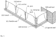
- FIG. 1 illustrates a perspective view of a Deployable Flexible Flood Wall with the wall in the deployed position 100 according to an embodiment of the present invention.
- FIG. 2 illustrates the Deployable Flexible Flood Wall 100 in its stowed condition with the cover removed.
- FIGS, 3 through 8 respectively illustrate detailed views of critical features of the Deployable Flexible Flood Wall 100 .
- the Deployable Flexible Flood Wall is also referred to as the Flex-Wall.
- the Deployable Flexible Flood Wall 100 is comprised of a textile & membrane flexible wall 101, a trench 102, a sealing clamp 103, a mounting plate 104, a post 105, a clamping post 106, a buttress 107, a receiver 108, a wall seal 109, a tether 110, an anchor 111, and cover 112 .
- the flexible wall 101 is folded and stored in the trench 102 and can be moved from a stowed to a deployed position and visa-versa.
- the flexible wall 101 is attached to the mounting plate 104 with the sealing clamp 103, and possibly the use of a deadman 113 termination to the flexible wall 101, to prevent pull-out from the sealing clamp 103.
- the sealing clamp 103 provided a leak-free seal between the flexible wall 101 and the mounting plate 104
- a gasket seal 114 is situated between the mounting plate 104, and the trench 102 to provide a leak-free seal.
- the cover 112 on the trench 102 In order to deploy the flexible wall 101, the cover 112 on the trench 102 must first be removed.
- the posts 105 are lifted or rotated into receivers 108 that are fixed to the mounting plate 104.
- the flexible wall 101 is then lifted vertically and attached to the posts 105 via a tether 110 on the flexible wall 101, and an anchor 111 on the post 105. Any water or other fluid impinging on the flexible wall 101 drives the load into the posts 105, and then into the receivers 108 where they are reacted by the trench 102.
- the flexible wall 101 can be stowed in a number of ways including rolling or folding.
- the flexible wall 101 can be terminated at a post 105 by clamping it between the post 105 and the clamping post 106.
- a gasket seal 114 on the clamping post 106 will seal the flexible wall 101 to prevent water pass by.
- a "deadman" 113 termination can be added to the ends of the wall to prevent pull-out when the wall is loaded.
- the sealing posts 106 can be located on any side of the post 105 for convenience. This clamping arrangement can be used to terminate the deployable flexible flood wall 100 against a building or structure, create a doorway along the span, create a join at a corner, or any other configuration required where the flexible wall 101 needs to be terminated or two flexible walls 101 joined in a leak-tree assembly.
- the post 105 can be fitted with a fixed or removable wall seal 109 to form a leak-free seal between the deployable flexible flood wall 100 and a building or structure.
- the deadman 1 07 is comprised of an inner core wrapped by a flexible wall webbing 115, flexible wall membrane 112.
- the inner core provides strength and a geometric feature that can't be compressed through the clamping systems.
- the webbing 115 is an extension of the webbing structure of the flexible wall 102.
- the webbings wrap around the inner core and are sewn to create a loop. This junction provides a path for loads from the flexible wall 10 1 to the mounting plate 104 and subsequently the trench 102.
- the mounting plate 104 may or may not be physically connected to the trench 102.
- a protective covering 113 may be added to improve resiliency to the flexible wall 101 if rough handling or impacts are anticipated.
- the webbings 115 can be joined at regular intervals via stitching, sealing, bonding, combinations thereof or some similar activity.
- the webbing 115 can be coated or impregnated with plastic or elastomeric coatings, or is can be uncoated.
- the membrane 116 is positioned adjacent to the webbing 115 assembly and is oversized to ensure load transfer in the webbing 115 assembly.
- the membrane 116 prevents water transmission past the flexible wall 101.
- the membrane can be any number of materials including polymer coated fabrics, elastomeric sheets, plastic films, etc. It should be understood that any of the fabric, webbings, straps, etc, can be created from high strength materials, such as KEVLAR®, graphite, glass, metal, ceramic, composite fibers and combinations thereof.
- Figs. 3A-3D illustrate some potential combinations of materials, which are for exemplary purposes only as those skilled in the art, upon reading this disclosure will envision equivalents and alternatives to the illustrated exemplary configurations.
- Figure 8 illustrates that for more highly stressed walls that resist higher water threats or impacts, a buttress 107 can be added to the post 105. This will reduce the bending loads in the posts 105 to keep them small and manageable, and reduce the torsional load in the trench 102 and allow it to be smaller.
Landscapes
- Engineering & Computer Science (AREA)
- General Engineering & Computer Science (AREA)
- Structural Engineering (AREA)
- Civil Engineering (AREA)
- Environmental & Geological Engineering (AREA)
- Ocean & Marine Engineering (AREA)
- Mechanical Engineering (AREA)
- Architecture (AREA)
- Buildings Adapted To Withstand Abnormal External Influences (AREA)
- Special Wing (AREA)
- Barrages (AREA)
Description
- The present invention relates to a Flexible Flood Mitigation Device system that is scalable in size, shape, and orientation to a wide variety of applications. The invention can be used to seal part or all of an opening from flood water or other fluid threats, or completely surround a building or structure for protection.
- Flooding events can be precipitated by natural and manmade inputs. These events can be particularly challenging for buildings and infrastructure located at or near a body of water. Transportation systems or buildings in these areas that are below the normal waterline are particularly vulnerable. Severe storms with high tidal surges or flash floods, rising sea levels, and seismic activity are some of the challenges posed by nature. Accidents, terrorism, and mechanical failures are manmade threats that can cause flooding, or magnify flooding from natural events.
- Many subway and vehicular tunnels that operate below waterline around the world have experienced flooding. Countless buildings and structures such as power substations have also experienced flooding. Hurricane Sandy was particularly devastating to New York City in 2012 because a significant portion of the subway system was flooded and economic losses were unprecedented. Water entrance points included subway portals, stairwell entrance points, ventilation shafts, emergency exits, and elevator shafts. Vehicular tunnels were also flooded, as well as many buildings. This was one of the worst flooding events in history, but it was just one in a string of events in subway systems in major cities around the world.
- There are many types of flood mitigation wall systems available commercially. This includes sand bags, inflatable walls, deployable mechanical wails, and flood doors. Most of these devices are stored remotely and transported to the point of use when needed. This requires the user to have extensive logistical plans and training in place to provide effective protection. Mechanical systems such as rigid doors that are stored at point-of-use often require significant modification to the infrastructure during installation, a considerable amount of storage space for concealment, frequent maintenance, and are costly to install. Because of this, they are often found to be unacceptable in numerous applications.
- Textile and membrane based Flexible Flood Mitigation Walls offer significant benefits over the existing wall devices. Most notable is the ability to pack the wall system into a small volume for point-of-use storage. This not only allows the Flexible Flood Mitigation Wall to be stored in a small volume that is compatible with space available, but it also minimizes the modifications required on the infrastructure to install it. The membrane wall itself is shaped to minimize stress in the material (governed by thin-walled pressure vessel equations, specifically pressure and radius). The wall is deployed by first removing the cover over its storage trench which is in-front of, or surrounding the opening/property to be protected. The posts, winch are stored in the trench with the membrane wall, are lifted and positioned in receivers. The fabric wall, which is attached to the trench along its base, is then raised and attached to the posts. When water, waves, and floating debris impact the wall, the loads are transferred from the fabric into the posts and then into the ground. The posts can be straight beams or can be buttressed for additional bending strength and control of loads in the trench. The flexible fabric wall can be constituted of one or several layers or different types of materials to provide protection from threats of all kinds including water pressure, wave action, floating debris impact, or even chemical threats.
- The Flexible Flood Mitigation Wail can follow any perimeter shape with positive and negative recesses, angular changes, or grade changes. It can be continuous and completely surround a structure, or simply bridge an opening and seal against the sides of the opening via the addition to sealing materials on the posts that abut the buildings.
- The Flexible Flood Mitigation Wall can also be used as a containment device that keeps a fluid inside an area and prevents its escape. This could be in the form of a deployable wall around a location where hazardous materials are used and spills are required to be contained.
-
US 4,321,774 relates to a flood barrier comprising a flexible membrane, the end and base part terminating in a beading of polypropylene rope. The side parts of the barrier are located in a vertical channel in the side walls and base in a horizontal extending channel in the floor. -
US 6,991,403 relates to a system for anchoring fabric panels having an anchor housing which includes a base, walls on the ends of the base, a chamber, and an extension attached to the first wall, wherein the extension projects over the chamber. This system is designed to allow rapid deployment of flood barriers, wind barriers, and other fabric barrier products. -
US 5,645,373 relates to temporary flood control barrier system comprising elongated flexible, inflatable, tubular ballast members secured to each other and adapted for anchoring a generally sheetlike vertically extendible barrier wall or an inflatable tubular barrier member disposed above and connected to the ballast members. The ballast members are at least partially fillable with a dense ballast liquid, such as water, and may be inflated with pressure air to add rigidity and increase the height of the flood control barrier system. -
DE 10 2012 005 329 relates to a flood protection wall with a pole bolt, with which one end introduces a bolt holder and another end introduces another bolt holder, wherein the pole bolt is detachably fixed in a tub by a bolt fixing unit. -
DE 10 2007 040 744 relates to temporary flood protection system, which has a partition provided between a side and a base-fixed partition edges in a support-free manner, wherein the partition is a textile inductile partition or a wall-partition. - According to the present invention, there is provided a deployable flexible fluid retention wall system according to claim 1 and claim 14. Dependent claims 2 to 13 and 15 define further features of the system.
- The Flexible Flood Mitigation Device is deployable wall that leverages the unique advantages of textile & membrane materials to advance the state of the art in flood mitigation devices.
- The Flexible Flood Mitigation Device is comprised of a textile and membrane wall, posts that support the wall when deployed, a base plate for mounting the post receivers and wall, and a trench with a protective cover.
- The flexible wall is folded and stored in the trench along with the posts until a potential flooding event is identified. At this time, the trench cover is removed, the posts are raised and inserted into their receivers; and the flexible wall is lifted and attached to the posts. When deployed, the wall will prevent the passage of water under significant hydrostatic pressure (from zero to approximately ten feet of pressure head). The wall terminates under a clamping bar and seal that are located at the base of the lough on a mounting plate. A deadman assembly can be used in conjunction with the clamp to prevent pull-out of the flexible wall when under load. After the event is over, the wall is detached from the posts, folded and stored back in the trench. The posts are then removed from their receivers and stored in the trench. The covers arc then reinstalled over the trench to protect the system. The covers can be applied with tamperproof fasteners or. hinges if desirable, and can also be load rated to withstand vehicle traffic.
- The wall assembly is stored below-ground at the point of use and is simple to deploy, so users can deploy their flood mitigation, system quickly and as close to the flooding event as possible. This-is important in high traffic applications such as transit systems or businesses, where downtime. equates to lost revenue. Point of use storage excludes the potential for lost parts fiver time when items are stored remotely. It also permanently fixes the seal of the fabric wall to the ground such that a high reliability system with no leakage is ensured. Most deployable systems cannot seal effectively to the ground because of surface roughness, cracks, and undulations in the surface, and therefore leak. This often results in the need for pumps to remove leakage of the water, and therefore power which is often unavailable in storm and flooding events.
- The trench and wall assembly can be designed to form a perimeter around a structure of any shape, and can include concave and convex features. It can be formed on slopes, across curbs, or can be placed above ground in the form of a bench. The trench, usually formed in concrete to react the loads from water impinging on the deployable wall, can be any shape or size to. accommodate short or tall walls. If the reaction loads on the trench from the post loads become prohibitive on the trench then a deployable buttress can be added to the posts. The buttress will direct loads to the landing point of the buttress and greatly reduce the loads induced on the trench. The spacing of the posts can also be altered to increase the strength of the wall when spaced close together, or reduce the cost of the wall by spreading them apart.
- The flexible wall assembly can prevent impingement of the wall, and thus force of the water, on the structure it is protecting (glass windows, etc.). This can be done by positioning the trench away from the structure, or by angling the posts away from the structure if the trench is near the structure. Independent flexible members (rope, cable, etc.) can be strung from the post top to the trench such that a channel or large series of belt loops is created, such that the wall will be captive and can be easily deployed in wind.
- The flexible wall system can abut and seal against structures such as buildings, walls, or doorways. This is accomplished by adding a seal between the last post and the building. The flexible wall can also have interruptions so passageways can be created that will allow the flow of pedestrian traffic until the last possible minute when sealing the wall is required. This is possible because the wall can start or stop at columns through the use of an overlapping wall sealing system. This is comprised of the flexible wall with a deadman assembly, being captured between two abutting posts. The deadman is a 'flexible assembly that is larger than the gap between the posts and therefore will not slip between the posts and is therefore permanently captured. Face seals on the posts in this area prevent leakage past the joined wall sections.
- A second aspect of the present disclosure is the use of a the same, or similar but less structural version, to be used as a protective barrier against human or vehicular traffic flow, wind, flying objects, etc. The functionality of the system is the same, but the forces on the system are potentially lower in these cases so different materials could be used.
-
-
FIG. 1 illustrates the assembly with a corner, and the flexible wall deployed -
FIG. 2 illustrates the assembly with a corner, and the flexible wall packed with the cover removed -
FIGS. 3A -3D illustrate several potential constructions of the fabric wall -
FIG. 4 illustrates the termination assembly of the flexible wall -
FIG. 5 illustrates the assembly in the packed state -
FIG. 6 illustrates the assembly in the deployed position -
FIG. 7 illustrates the assembly in the deployed position at a building / structure abutment -
FIG. 8 illustrates the assembly in the deployed position with a buttress -
FIG. 1 illustrates a perspective view of a Deployable Flexible Flood Wall with the wall in the deployed position 100 according to an embodiment of the present invention.FIG. 2 illustrates the Deployable Flexible Flood Wall 100 in its stowed condition with the cover removed.FIGS, 3 through 8 respectively illustrate detailed views of critical features of the Deployable Flexible Flood Wall 100. The Deployable Flexible Flood Wall is also referred to as the Flex-Wall. - As shown in
FIGS. 1 ,2 ,5 ,6 and 7 , the Deployable Flexible Flood Wall 100 is comprised of a textile & membraneflexible wall 101, atrench 102, a sealingclamp 103, a mountingplate 104, apost 105, a clampingpost 106, abuttress 107, areceiver 108, awall seal 109, atether 110, ananchor 111, and cover 112 . - The
flexible wall 101 is folded and stored in thetrench 102 and can be moved from a stowed to a deployed position and visa-versa. Theflexible wall 101 is attached to the mountingplate 104 with the sealingclamp 103, and possibly the use of adeadman 113 termination to theflexible wall 101, to prevent pull-out from the sealingclamp 103. The sealingclamp 103 provided a leak-free seal between theflexible wall 101 and the mountingplate 104, Agasket seal 114 is situated between the mountingplate 104, and thetrench 102 to provide a leak-free seal. In order to deploy theflexible wall 101, thecover 112 on thetrench 102 must first be removed. Theposts 105 are lifted or rotated intoreceivers 108 that are fixed to the mountingplate 104. Theflexible wall 101 is then lifted vertically and attached to theposts 105 via atether 110 on theflexible wall 101, and ananchor 111 on thepost 105. Any water or other fluid impinging on theflexible wall 101 drives the load into theposts 105, and then into thereceivers 108 where they are reacted by thetrench 102. Theflexible wall 101 can be stowed in a number of ways including rolling or folding. - The
flexible wall 101 can be terminated at apost 105 by clamping it between thepost 105 and the clampingpost 106. Agasket seal 114 on the clampingpost 106 will seal theflexible wall 101 to prevent water pass by. A "deadman" 113 termination can be added to the ends of the wall to prevent pull-out when the wall is loaded. The sealing posts 106 can be located on any side of thepost 105 for convenience. This clamping arrangement can be used to terminate the deployable flexible flood wall 100 against a building or structure, create a doorway along the span, create a join at a corner, or any other configuration required where theflexible wall 101 needs to be terminated or twoflexible walls 101 joined in a leak-tree assembly. Thepost 105 can be fitted with a fixed orremovable wall seal 109 to form a leak-free seal between the deployable flexible flood wall 100 and a building or structure. - As shown in
FIGS. 4 and 5 the deadman 1 07 is comprised of an inner core wrapped by aflexible wall webbing 115,flexible wall membrane 112. The inner core provides strength and a geometric feature that can't be compressed through the clamping systems. Thewebbing 115 is an extension of the webbing structure of theflexible wall 102. The webbings wrap around the inner core and are sewn to create a loop. This junction provides a path for loads from the flexible wall 10 1 to the mountingplate 104 and subsequently thetrench 102. The mountingplate 104 may or may not be physically connected to thetrench 102. Aprotective covering 113 may be added to improve resiliency to theflexible wall 101 if rough handling or impacts are anticipated. Thewebbings 115 can be joined at regular intervals via stitching, sealing, bonding, combinations thereof or some similar activity. Thewebbing 115 can be coated or impregnated with plastic or elastomeric coatings, or is can be uncoated. Themembrane 116 is positioned adjacent to thewebbing 115 assembly and is oversized to ensure load transfer in thewebbing 115 assembly. Themembrane 116 prevents water transmission past theflexible wall 101. The membrane can be any number of materials including polymer coated fabrics, elastomeric sheets, plastic films, etc. It should be understood that any of the fabric, webbings, straps, etc, can be created from high strength materials, such as KEVLAR®, graphite, glass, metal, ceramic, composite fibers and combinations thereof.Figs. 3A-3D illustrate some potential combinations of materials, which are for exemplary purposes only as those skilled in the art, upon reading this disclosure will envision equivalents and alternatives to the illustrated exemplary configurations. -
Figure 8 illustrates that for more highly stressed walls that resist higher water threats or impacts, a buttress 107 can be added to thepost 105. This will reduce the bending loads in theposts 105 to keep them small and manageable, and reduce the torsional load in thetrench 102 and allow it to be smaller.
Claims (15)
- A deployable flexible fluid retention wall system (100) comprising: a membrane flexible wall (101); the flexible wall (101) comprising at least a lower end thereof; a series of rigid posts (105) that support the flexible wall (101); a trench (102); a cover (112) for the trench; each of the series of posts (105) being initially contained within the trench (102) and beneath the cover (112) when the posts (105) are in a stowed position such that the posts (105) are protected from exposure to the environment by the cover for the trench (102); the trench (102) further comprising a mounting plate (104) at the bottom of the trench (102); and the mounting plate (104) additionally comprising a plurality of receivers (108), each receiver (108) being fixed to the mounting plate (104) and sized so as to receive the lower end of the post (105) when the post (105) is in its deployed position and which receiver (108) is also protected from exposure to the environment by the cover (112) for the trench (102) ; and a clamping bar (103) and a seal (114); the flexible wall (101) being attached to the posts (105); characterised in that the lower end of the flexible wall (100) is attached between the clamping bar (103) and the seal (114) to the mounting plate (104) within the trench (102) to prevent the passage of fluid beyond the flexible wall (101).
- The deployable flexible wall system (100) of claim 1, wherein the flexible wall (101) is comprised of one selected from the group consisting of one and multiple layers of material, wherein said one or multiple layers of material provide fluid retention and structural support to restrain static and dynamic fluid pressure, and floating debris impacts.
- The deployable flexible wall system (100) of claim 2, wherein the flexible wall (101) is concavely shaped to reduce stress in the flexible wall (101).
- The deployable flexible wall system (100) of claim 2, wherein the flexible wall (101) is comprised of a least one member selected from the group consisting of fabric, webbing, straps, belts, tapes and combinations thereof, for structural support.
- The deployable flexible wall system (100) of claim 2, wherein the flexible wall (101) is comprised of a coated fabric or membrane for fluid retention.
- The deployable flexible wall system (100) of claim 2, wherein at least some of the perimeter of the flexible wall (101) is comprised of a deadman (113) which is connected to the flexible wall (101) by surrounding the deadman (113) with at least one selected from the group consisting of said one layer and multiple layers of material that provide structural support and fluid retention.
- The deployable flexible wall system (100) of claim 6, wherein the deadman (113) transmits the load from the flexible wall (101) into at least one selected from the group consisting of the posts (105) and mounting plate (104).
- The deployable flexible wall system (100) of claim 2, wherein the flexible nature of the flexible wall (101) facilitates at least one of rolling, folding and combinations thereof, of the flexible wall (101) for storage.
- The deployable flexible wall system (100) of claim 1, further comprising at least one clamping post (106) wherein one or more posts (105) and the clamping post (106) are situated together to clamp the flexible wall (101) and react to loading.
- The deployable flexible wall system (100) of claim 1, wherein the flexible wall (101) is terminated and sealed at a post location.
- The deployable flexible wall system (100) of claim 1, where the flexible wall (101) is sealed against a structure, building or opening in a building.
- The deployable flexible wall system (100) of claim 1, wherein the lower end of the flexible wall (101) comprises a deadman (113) and the deadman (113) prevents pull-out of the flexible wall (101) from the clamping bar (103) under load.
- The deployable flexible wall system (100) of claim 1, wherein the flexible wall (101) is used to stop the flow of liquid.
- A deployable flexible fluid retention wall system (100) comprising:a membrane flexible wall (101); a series of rigid posts (105) that support the flexible wall (101);at least one clamping post (106);a trench (102) and a cover (112) for the trench (102);each of the series of posts (105), and the at least one clamping post (106), being initially contained within the trench (102) and beneath the cover (112) when the posts (105) and the at least one clamping post (106), are in a stowed position such that the posts (105) and the at least one clamping post (106) are protected from exposure to the environment by the cover (112) for the trench (102); the trench (102) further comprising a mounting plate (104) at the bottom of the trench (102); and the mounting plate (104) additionally comprising a plurality of receivers (108), each receiver (108) being fixed to the mounting plate (104), and sized so as to receive the lower end of the post (105) when the post (105) is in its deployed position and which receiver (108) is also protected from exposure to the environment by the cover (112) for the trench (102);the trench (102) being sized and shaped so as to stow the membrane flexible wall (101), the series of rigid posts (105) and the at least one clamping post (106) in the trench (102) beneath the cover (112) for the trench (102) when the membrane flexible wall (101) is not deployed;a clamping bar (103) and a seal (114); a lower end of the flexible wall (101) being attached between the clamping bar (103) and seal (114) to the mounting plate (104); and,a gasket seal (114); the gasket seal (114) being on the at least one clamping post (106);characterised in that a portion of the flexible wall (101) is also clamped between at least one of said rigid posts (105) and the at least one clamping post (106).
- The deployable flexible wall system (100) of claim 14, wherein the lower end of the flexible wall (101) comprises a deadman (113) and the deadman (113) prevents pull-out of the flexible wall (101) from the clamping bar (103) under load.
Priority Applications (1)
| Application Number | Priority Date | Filing Date | Title |
|---|---|---|---|
| PL14902096T PL3194661T3 (en) | 2014-09-18 | 2014-10-16 | Deployable flexible fluid retention wall system |
Applications Claiming Priority (2)
| Application Number | Priority Date | Filing Date | Title |
|---|---|---|---|
| US14/490,058 US9453314B2 (en) | 2014-09-18 | 2014-09-18 | Deployable flexible flood mitigation wall |
| PCT/US2014/060894 WO2016043785A1 (en) | 2014-09-18 | 2014-10-16 | Deployable flexible flood mitigation wall |
Publications (3)
| Publication Number | Publication Date |
|---|---|
| EP3194661A1 EP3194661A1 (en) | 2017-07-26 |
| EP3194661A4 EP3194661A4 (en) | 2018-06-20 |
| EP3194661B1 true EP3194661B1 (en) | 2020-01-01 |
Family
ID=55525235
Family Applications (1)
| Application Number | Title | Priority Date | Filing Date |
|---|---|---|---|
| EP14902096.8A Active EP3194661B1 (en) | 2014-09-18 | 2014-10-16 | Deployable flexible fluid retention wall system |
Country Status (12)
| Country | Link |
|---|---|
| US (1) | US9453314B2 (en) |
| EP (1) | EP3194661B1 (en) |
| JP (2) | JP2017533358A (en) |
| KR (2) | KR20170058929A (en) |
| CN (1) | CN107075825B (en) |
| AU (1) | AU2014406459B2 (en) |
| CA (1) | CA2961365C (en) |
| DK (1) | DK3194661T3 (en) |
| ES (1) | ES2775227T3 (en) |
| PL (1) | PL3194661T3 (en) |
| PT (1) | PT3194661T (en) |
| WO (1) | WO2016043785A1 (en) |
Families Citing this family (20)
| Publication number | Priority date | Publication date | Assignee | Title |
|---|---|---|---|---|
| US11795645B2 (en) * | 2011-10-31 | 2023-10-24 | Gary E. Abeles | Portable water inflatable barrier integral with support base |
| US11060313B2 (en) * | 2018-05-11 | 2021-07-13 | Ghw Solutions, Llc | Systems and methods for flood prevention and pest control |
| AU2019265220B2 (en) * | 2018-05-11 | 2020-12-24 | Innoventive Solutions Pty Ltd | A barrier system |
| CN108843187A (en) * | 2018-06-22 | 2018-11-20 | 邵珠冉 | A kind of liftable flexible water blocking threshold |
| JP6467747B1 (en) * | 2018-08-16 | 2019-02-13 | 日新興業株式会社 | View window structure of the embankment |
| US11885121B2 (en) * | 2019-01-30 | 2024-01-30 | Donald Ouimette | System and method for protecting structures |
| US10557239B1 (en) * | 2019-03-19 | 2020-02-11 | Kevin Malaney | Inflatable flood barrier |
| US10927520B1 (en) | 2020-02-07 | 2021-02-23 | Mooring Manufacturing LLC | Watertight flexible flood barrier system |
| US11313097B2 (en) * | 2020-04-15 | 2022-04-26 | George Mason University | Dynamically deployable low-visibility pneumatic cofferdam system, method and apparatus |
| CN112081067B (en) * | 2020-08-20 | 2022-05-06 | 童宗明 | Combined flood prevention plate based on guide plate shunting buffering |
| US11255100B1 (en) * | 2020-08-21 | 2022-02-22 | Christopher T. Hughes | Permanent below ground flood barrier installation |
| US11702810B2 (en) * | 2021-01-22 | 2023-07-18 | The United States Of America, As Represented By The Secretary Of The Navy | Barrier for hazardous liquids |
| GB2607597A (en) * | 2021-06-07 | 2022-12-14 | Hanchant Penny | Modular flood defence barrier system |
| TWI768983B (en) * | 2021-06-23 | 2022-06-21 | 國立成功大學 | Membrane flood barrier |
| CN113684911B (en) * | 2021-08-17 | 2023-03-10 | 山东红三叶钢结构工程有限公司 | Over-and-under type flood control ground storehouse structure |
| WO2023076750A1 (en) * | 2021-11-01 | 2023-05-04 | Near Space Corporation | Deployable structures |
| CN115434285A (en) * | 2022-10-24 | 2022-12-06 | 江苏永景水利科技有限公司 | Flood control device |
| JP7551962B1 (en) * | 2023-03-29 | 2024-09-17 | バンドー化学株式会社 | Flood prevention system and flood prevention method |
| JP7551963B1 (en) * | 2023-03-29 | 2024-09-17 | バンドー化学株式会社 | Flood prevention system and flood prevention method |
| JP7478314B1 (en) * | 2023-03-29 | 2024-05-02 | バンドー化学株式会社 | Flood prevention system and flood prevention method |
Family Cites Families (45)
| Publication number | Priority date | Publication date | Assignee | Title |
|---|---|---|---|---|
| CA1068913A (en) * | 1977-09-28 | 1980-01-01 | Leigh Flexible Structures Ltd. | Portable dams |
| US4321774A (en) | 1980-05-20 | 1982-03-30 | Leigh Flexible Structures Limited | Flood barrier |
| US4458456A (en) * | 1980-08-29 | 1984-07-10 | Battle Daniel S | Apparatus and method for protecting structures from flooding water |
| US4375929A (en) * | 1980-09-02 | 1983-03-08 | Clark Travis B | Protective flood barrier |
| DE3527100A1 (en) * | 1985-07-29 | 1987-02-05 | Mehler Ag V | Device for protection against high-water |
| JPS63147071A (en) * | 1986-12-08 | 1988-06-20 | 日本鋼管株式会社 | Base material for blocking running water |
| US4787774A (en) * | 1987-07-01 | 1988-11-29 | Grove William M | Fluid control apparatus |
| JP2849871B2 (en) * | 1990-11-16 | 1999-01-27 | 株式会社大和エンジニヤリング | Land lock |
| US5460462A (en) * | 1993-09-09 | 1995-10-24 | Regan; Patrick | Liquid and flood water barrier wall forming-apparatus |
| US5645373A (en) | 1995-07-11 | 1997-07-08 | Maca/Orsi, L.L.C. | Flood control barrier system and method |
| SE505394C2 (en) | 1995-11-14 | 1997-08-18 | Sahbi Belarbi | flood |
| GB2327971B (en) | 1997-08-09 | 2002-03-13 | Malcolm Baxter | Flood protection device |
| CA2254790A1 (en) | 1998-03-23 | 1999-09-23 | Equipement Industriel Gba Inc. | Flood control barrier |
| US6029405A (en) * | 1998-04-23 | 2000-02-29 | Wood; Barbara A. | Apparatus and method for inhibiting water from entering a structure |
| US5988946A (en) * | 1998-05-27 | 1999-11-23 | Reed; Charles | Multiple bladder flood control system |
| JP2001227255A (en) * | 2000-02-18 | 2001-08-24 | Suzuki Shutter Mfg Co Ltd | Tide plate device |
| DE10040047A1 (en) * | 2000-08-11 | 2002-02-28 | Hierl Elisabeth | Temporary protection device |
| US6460299B1 (en) | 2000-08-15 | 2002-10-08 | Linda R. Burrow | Flood protection assembly |
| US6425213B1 (en) | 2000-11-01 | 2002-07-30 | Gilles Lachapelle | Water impermeable adhering liner device for structure protection against natural disasters and method of using the same |
| JP2004514814A (en) | 2000-12-01 | 2004-05-20 | ブレイク,テリー | Flood barrier |
| NO314414B1 (en) | 2001-03-16 | 2003-03-17 | Aquafence As | A flood barrier section and a flood barrier |
| US6443655B1 (en) | 2001-04-21 | 2002-09-03 | Robert Bennett | Flood barrier |
| US6991403B1 (en) | 2004-09-15 | 2006-01-31 | Hendee Charles C | System for anchoring fabric panels |
| FR2876716B1 (en) * | 2004-10-18 | 2007-03-16 | Cie Du Sol Soc Civ Ile | DEVICE FOR PRODUCING ANTI-CRANE SEALED BARRIER |
| JP2007231574A (en) * | 2006-02-28 | 2007-09-13 | Kaneso Co Ltd | Water cut-off device |
| US7214005B1 (en) | 2006-06-12 | 2007-05-08 | Davis George T | Sectionalized flood control barrier |
| US7712998B2 (en) | 2007-04-13 | 2010-05-11 | Bernard Salemie | Flood wall |
| DE102007037476A1 (en) | 2007-08-08 | 2009-04-23 | Adam Gillich | Flexible wall covering for building, providing protection against flooding by high water level, comprises plastic tarpaulin anchored-down in surrounding trench |
| US7614825B2 (en) | 2007-08-09 | 2009-11-10 | Polystar Incorporated | Deployable containment system |
| DE102007040744A1 (en) * | 2007-08-28 | 2009-03-05 | Stev Bringmann | Temporary flood protection system, has partition provided between base side and base-fixed partition edges in support-free manner, where partition is textile inductile partition or double-walled partition |
| GB0801290D0 (en) | 2008-01-24 | 2008-03-05 | Cintec Int Ltd | Inflatable flood defence |
| DE202008010500U1 (en) * | 2008-08-07 | 2010-11-11 | Limonow, Aleksej | Flood barrier to protect against flooding |
| JP5357472B2 (en) * | 2008-09-08 | 2013-12-04 | 重治 面来 | Water stop device |
| US7690865B1 (en) | 2009-07-21 | 2010-04-06 | Stewart Tommy D | Flood prevention device |
| US7976240B2 (en) | 2009-08-27 | 2011-07-12 | Mun Kam C | Flood barrier |
| DE102010046504A1 (en) * | 2010-09-24 | 2012-03-29 | Hartmut Wibbeler | Flood protection wall |
| CN102561272B (en) * | 2010-12-17 | 2014-02-12 | 上海华滋奔腾防汛设备制造有限公司 | Flexibly-foldable movable flood control gate |
| DE102012005329A1 (en) * | 2012-03-19 | 2013-09-19 | Hartmut Wibbeler | Flood protection wall has pole bolt, with which one end introduces bolt holder and another end introduces another bolt holder, where pole bolt is detachably fixed in tub by bolt fixing unit |
| JP5955599B2 (en) * | 2012-03-27 | 2016-07-20 | 文化シヤッター株式会社 | Inundation prevention device |
| CZ306685B6 (en) | 2012-07-18 | 2017-05-10 | Eismann | A device for protection of buildings against floods |
| KR101395741B1 (en) * | 2012-09-12 | 2014-05-16 | 부산대학교 산학협력단 | Water-proof Sheet, Method for Manufacturing the Sheet, and Apparatus Using the Sheet |
| JP6148807B2 (en) * | 2012-11-10 | 2017-06-14 | 大同機工株式会社 | Sheet-type flood prevention device |
| JP3181355U (en) * | 2012-11-21 | 2013-01-31 | 株式会社日本ピット | Entrance closing device in building |
| GB201310847D0 (en) * | 2013-06-18 | 2013-07-31 | Flood Control Internat Ltd | Flood barrier |
| CN203701050U (en) * | 2014-02-18 | 2014-07-09 | 亓勇 | Light flexible flood control device for hydraulic engineering |
-
2014
- 2014-09-18 US US14/490,058 patent/US9453314B2/en active Active
- 2014-10-16 PL PL14902096T patent/PL3194661T3/en unknown
- 2014-10-16 WO PCT/US2014/060894 patent/WO2016043785A1/en not_active Ceased
- 2014-10-16 AU AU2014406459A patent/AU2014406459B2/en active Active
- 2014-10-16 EP EP14902096.8A patent/EP3194661B1/en active Active
- 2014-10-16 KR KR1020177007323A patent/KR20170058929A/en not_active Ceased
- 2014-10-16 ES ES14902096T patent/ES2775227T3/en active Active
- 2014-10-16 CA CA2961365A patent/CA2961365C/en active Active
- 2014-10-16 JP JP2017516957A patent/JP2017533358A/en active Pending
- 2014-10-16 DK DK14902096.8T patent/DK3194661T3/en active
- 2014-10-16 CN CN201480081993.8A patent/CN107075825B/en active Active
- 2014-10-16 KR KR1020197022350A patent/KR102190234B1/en active Active
- 2014-10-16 PT PT149020968T patent/PT3194661T/en unknown
-
2018
- 2018-07-05 JP JP2018128398A patent/JP6676707B2/en active Active
Non-Patent Citations (1)
| Title |
|---|
| None * |
Also Published As
| Publication number | Publication date |
|---|---|
| DK3194661T3 (en) | 2020-04-06 |
| CN107075825B (en) | 2019-07-02 |
| ES2775227T3 (en) | 2020-07-24 |
| US9453314B2 (en) | 2016-09-27 |
| PL3194661T3 (en) | 2020-07-27 |
| KR20170058929A (en) | 2017-05-29 |
| US20160083918A1 (en) | 2016-03-24 |
| KR20190095494A (en) | 2019-08-14 |
| JP6676707B2 (en) | 2020-04-08 |
| CA2961365A1 (en) | 2016-03-24 |
| CA2961365C (en) | 2018-04-03 |
| CN107075825A (en) | 2017-08-18 |
| PT3194661T (en) | 2020-03-06 |
| JP2018178707A (en) | 2018-11-15 |
| AU2014406459A1 (en) | 2017-04-06 |
| JP2017533358A (en) | 2017-11-09 |
| EP3194661A1 (en) | 2017-07-26 |
| AU2014406459B2 (en) | 2017-06-29 |
| KR102190234B1 (en) | 2020-12-11 |
| EP3194661A4 (en) | 2018-06-20 |
| WO2016043785A1 (en) | 2016-03-24 |
Similar Documents
| Publication | Publication Date | Title |
|---|---|---|
| CA2961365C (en) | Deployable flexible flood mitigation wall | |
| EP3277890B1 (en) | Extendible flexible flood barrier | |
| EP3052721B1 (en) | Deployable flexible flood mitigation device | |
| CA2379559A1 (en) | A rapid emergency dam | |
| US20170233966A1 (en) | Integrated marine barrier | |
| WO2016057136A1 (en) | Portable flexible sealing device for grated openings | |
| US10240310B2 (en) | Berm or levee expansion system and method | |
| DE102014006783A1 (en) | System for protecting a building during flood | |
| WO2021077362A1 (en) | Portable modular air and water inflatable barrier system | |
| GB2347709A (en) | Emergency dam |
Legal Events
| Date | Code | Title | Description |
|---|---|---|---|
| STAA | Information on the status of an ep patent application or granted ep patent |
Free format text: STATUS: THE INTERNATIONAL PUBLICATION HAS BEEN MADE |
|
| PUAI | Public reference made under article 153(3) epc to a published international application that has entered the european phase |
Free format text: ORIGINAL CODE: 0009012 |
|
| STAA | Information on the status of an ep patent application or granted ep patent |
Free format text: STATUS: REQUEST FOR EXAMINATION WAS MADE |
|
| 17P | Request for examination filed |
Effective date: 20170413 |
|
| AK | Designated contracting states |
Kind code of ref document: A1 Designated state(s): AL AT BE BG CH CY CZ DE DK EE ES FI FR GB GR HR HU IE IS IT LI LT LU LV MC MK MT NL NO PL PT RO RS SE SI SK SM TR |
|
| AX | Request for extension of the european patent |
Extension state: BA ME |
|
| DAX | Request for extension of the european patent (deleted) | ||
| REG | Reference to a national code |
Ref country code: DE Ref legal event code: R079 Ref document number: 602014059532 Country of ref document: DE Free format text: PREVIOUS MAIN CLASS: E02B0007020000 Ipc: E02B0003100000 |
|
| A4 | Supplementary search report drawn up and despatched |
Effective date: 20180518 |
|
| RIC1 | Information provided on ipc code assigned before grant |
Ipc: E02B 3/10 20060101AFI20180514BHEP |
|
| STAA | Information on the status of an ep patent application or granted ep patent |
Free format text: STATUS: EXAMINATION IS IN PROGRESS |
|
| 17Q | First examination report despatched |
Effective date: 20190424 |
|
| GRAP | Despatch of communication of intention to grant a patent |
Free format text: ORIGINAL CODE: EPIDOSNIGR1 |
|
| STAA | Information on the status of an ep patent application or granted ep patent |
Free format text: STATUS: GRANT OF PATENT IS INTENDED |
|
| INTG | Intention to grant announced |
Effective date: 20190724 |
|
| GRAS | Grant fee paid |
Free format text: ORIGINAL CODE: EPIDOSNIGR3 |
|
| GRAA | (expected) grant |
Free format text: ORIGINAL CODE: 0009210 |
|
| STAA | Information on the status of an ep patent application or granted ep patent |
Free format text: STATUS: THE PATENT HAS BEEN GRANTED |
|
| AK | Designated contracting states |
Kind code of ref document: B1 Designated state(s): AL AT BE BG CH CY CZ DE DK EE ES FI FR GB GR HR HU IE IS IT LI LT LU LV MC MK MT NL NO PL PT RO RS SE SI SK SM TR |
|
| REG | Reference to a national code |
Ref country code: GB Ref legal event code: FG4D |
|
| REG | Reference to a national code |
Ref country code: CH Ref legal event code: EP Ref country code: AT Ref legal event code: REF Ref document number: 1219915 Country of ref document: AT Kind code of ref document: T Effective date: 20200115 |
|
| REG | Reference to a national code |
Ref country code: IE Ref legal event code: FG4D |
|
| REG | Reference to a national code |
Ref country code: DE Ref legal event code: R096 Ref document number: 602014059532 Country of ref document: DE |
|
| REG | Reference to a national code |
Ref country code: PT Ref legal event code: SC4A Ref document number: 3194661 Country of ref document: PT Date of ref document: 20200306 Kind code of ref document: T Free format text: AVAILABILITY OF NATIONAL TRANSLATION Effective date: 20200302 |
|
| REG | Reference to a national code |
Ref country code: CH Ref legal event code: NV Representative=s name: ISLER AND PEDRAZZINI AG, CH |
|
| REG | Reference to a national code |
Ref country code: DK Ref legal event code: T3 Effective date: 20200401 |
|
| REG | Reference to a national code |
Ref country code: NL Ref legal event code: FP |
|
| REG | Reference to a national code |
Ref country code: LT Ref legal event code: MG4D |
|
| REG | Reference to a national code |
Ref country code: ES Ref legal event code: FG2A Ref document number: 2775227 Country of ref document: ES Kind code of ref document: T3 Effective date: 20200724 |
|
| PG25 | Lapsed in a contracting state [announced via postgrant information from national office to epo] |
Ref country code: NO Free format text: LAPSE BECAUSE OF FAILURE TO SUBMIT A TRANSLATION OF THE DESCRIPTION OR TO PAY THE FEE WITHIN THE PRESCRIBED TIME-LIMIT Effective date: 20200401 Ref country code: LT Free format text: LAPSE BECAUSE OF FAILURE TO SUBMIT A TRANSLATION OF THE DESCRIPTION OR TO PAY THE FEE WITHIN THE PRESCRIBED TIME-LIMIT Effective date: 20200101 Ref country code: CZ Free format text: LAPSE BECAUSE OF FAILURE TO SUBMIT A TRANSLATION OF THE DESCRIPTION OR TO PAY THE FEE WITHIN THE PRESCRIBED TIME-LIMIT Effective date: 20200101 Ref country code: FI Free format text: LAPSE BECAUSE OF FAILURE TO SUBMIT A TRANSLATION OF THE DESCRIPTION OR TO PAY THE FEE WITHIN THE PRESCRIBED TIME-LIMIT Effective date: 20200101 Ref country code: RS Free format text: LAPSE BECAUSE OF FAILURE TO SUBMIT A TRANSLATION OF THE DESCRIPTION OR TO PAY THE FEE WITHIN THE PRESCRIBED TIME-LIMIT Effective date: 20200101 |
|
| PG25 | Lapsed in a contracting state [announced via postgrant information from national office to epo] |
Ref country code: SE Free format text: LAPSE BECAUSE OF FAILURE TO SUBMIT A TRANSLATION OF THE DESCRIPTION OR TO PAY THE FEE WITHIN THE PRESCRIBED TIME-LIMIT Effective date: 20200101 Ref country code: HR Free format text: LAPSE BECAUSE OF FAILURE TO SUBMIT A TRANSLATION OF THE DESCRIPTION OR TO PAY THE FEE WITHIN THE PRESCRIBED TIME-LIMIT Effective date: 20200101 Ref country code: LV Free format text: LAPSE BECAUSE OF FAILURE TO SUBMIT A TRANSLATION OF THE DESCRIPTION OR TO PAY THE FEE WITHIN THE PRESCRIBED TIME-LIMIT Effective date: 20200101 Ref country code: IS Free format text: LAPSE BECAUSE OF FAILURE TO SUBMIT A TRANSLATION OF THE DESCRIPTION OR TO PAY THE FEE WITHIN THE PRESCRIBED TIME-LIMIT Effective date: 20200501 Ref country code: GR Free format text: LAPSE BECAUSE OF FAILURE TO SUBMIT A TRANSLATION OF THE DESCRIPTION OR TO PAY THE FEE WITHIN THE PRESCRIBED TIME-LIMIT Effective date: 20200402 Ref country code: BG Free format text: LAPSE BECAUSE OF FAILURE TO SUBMIT A TRANSLATION OF THE DESCRIPTION OR TO PAY THE FEE WITHIN THE PRESCRIBED TIME-LIMIT Effective date: 20200401 |
|
| REG | Reference to a national code |
Ref country code: DE Ref legal event code: R097 Ref document number: 602014059532 Country of ref document: DE |
|
| PG25 | Lapsed in a contracting state [announced via postgrant information from national office to epo] |
Ref country code: RO Free format text: LAPSE BECAUSE OF FAILURE TO SUBMIT A TRANSLATION OF THE DESCRIPTION OR TO PAY THE FEE WITHIN THE PRESCRIBED TIME-LIMIT Effective date: 20200101 Ref country code: SM Free format text: LAPSE BECAUSE OF FAILURE TO SUBMIT A TRANSLATION OF THE DESCRIPTION OR TO PAY THE FEE WITHIN THE PRESCRIBED TIME-LIMIT Effective date: 20200101 Ref country code: EE Free format text: LAPSE BECAUSE OF FAILURE TO SUBMIT A TRANSLATION OF THE DESCRIPTION OR TO PAY THE FEE WITHIN THE PRESCRIBED TIME-LIMIT Effective date: 20200101 Ref country code: SK Free format text: LAPSE BECAUSE OF FAILURE TO SUBMIT A TRANSLATION OF THE DESCRIPTION OR TO PAY THE FEE WITHIN THE PRESCRIBED TIME-LIMIT Effective date: 20200101 |
|
| PLBE | No opposition filed within time limit |
Free format text: ORIGINAL CODE: 0009261 |
|
| STAA | Information on the status of an ep patent application or granted ep patent |
Free format text: STATUS: NO OPPOSITION FILED WITHIN TIME LIMIT |
|
| REG | Reference to a national code |
Ref country code: AT Ref legal event code: MK05 Ref document number: 1219915 Country of ref document: AT Kind code of ref document: T Effective date: 20200101 |
|
| 26N | No opposition filed |
Effective date: 20201002 |
|
| PG25 | Lapsed in a contracting state [announced via postgrant information from national office to epo] |
Ref country code: AT Free format text: LAPSE BECAUSE OF FAILURE TO SUBMIT A TRANSLATION OF THE DESCRIPTION OR TO PAY THE FEE WITHIN THE PRESCRIBED TIME-LIMIT Effective date: 20200101 |
|
| PG25 | Lapsed in a contracting state [announced via postgrant information from national office to epo] |
Ref country code: SI Free format text: LAPSE BECAUSE OF FAILURE TO SUBMIT A TRANSLATION OF THE DESCRIPTION OR TO PAY THE FEE WITHIN THE PRESCRIBED TIME-LIMIT Effective date: 20200101 |
|
| PG25 | Lapsed in a contracting state [announced via postgrant information from national office to epo] |
Ref country code: MC Free format text: LAPSE BECAUSE OF FAILURE TO SUBMIT A TRANSLATION OF THE DESCRIPTION OR TO PAY THE FEE WITHIN THE PRESCRIBED TIME-LIMIT Effective date: 20200101 |
|
| PG25 | Lapsed in a contracting state [announced via postgrant information from national office to epo] |
Ref country code: TR Free format text: LAPSE BECAUSE OF FAILURE TO SUBMIT A TRANSLATION OF THE DESCRIPTION OR TO PAY THE FEE WITHIN THE PRESCRIBED TIME-LIMIT Effective date: 20200101 Ref country code: MT Free format text: LAPSE BECAUSE OF FAILURE TO SUBMIT A TRANSLATION OF THE DESCRIPTION OR TO PAY THE FEE WITHIN THE PRESCRIBED TIME-LIMIT Effective date: 20200101 Ref country code: CY Free format text: LAPSE BECAUSE OF FAILURE TO SUBMIT A TRANSLATION OF THE DESCRIPTION OR TO PAY THE FEE WITHIN THE PRESCRIBED TIME-LIMIT Effective date: 20200101 |
|
| PG25 | Lapsed in a contracting state [announced via postgrant information from national office to epo] |
Ref country code: MK Free format text: LAPSE BECAUSE OF FAILURE TO SUBMIT A TRANSLATION OF THE DESCRIPTION OR TO PAY THE FEE WITHIN THE PRESCRIBED TIME-LIMIT Effective date: 20200101 Ref country code: AL Free format text: LAPSE BECAUSE OF FAILURE TO SUBMIT A TRANSLATION OF THE DESCRIPTION OR TO PAY THE FEE WITHIN THE PRESCRIBED TIME-LIMIT Effective date: 20200101 |
|
| PGFP | Annual fee paid to national office [announced via postgrant information from national office to epo] |
Ref country code: FR Payment date: 20221025 Year of fee payment: 9 |
|
| PGFP | Annual fee paid to national office [announced via postgrant information from national office to epo] |
Ref country code: PT Payment date: 20221003 Year of fee payment: 9 Ref country code: LU Payment date: 20221027 Year of fee payment: 9 Ref country code: IT Payment date: 20221020 Year of fee payment: 9 Ref country code: ES Payment date: 20221102 Year of fee payment: 9 Ref country code: DK Payment date: 20221027 Year of fee payment: 9 |
|
| PGFP | Annual fee paid to national office [announced via postgrant information from national office to epo] |
Ref country code: PL Payment date: 20221003 Year of fee payment: 9 Ref country code: CH Payment date: 20221116 Year of fee payment: 9 Ref country code: BE Payment date: 20221027 Year of fee payment: 9 |
|
| P01 | Opt-out of the competence of the unified patent court (upc) registered |
Effective date: 20230528 |
|
| REG | Reference to a national code |
Ref country code: CH Ref legal event code: PL |
|
| REG | Reference to a national code |
Ref country code: DK Ref legal event code: EBP Effective date: 20231031 |
|
| REG | Reference to a national code |
Ref country code: BE Ref legal event code: MM Effective date: 20231031 |
|
| PG25 | Lapsed in a contracting state [announced via postgrant information from national office to epo] |
Ref country code: LU Free format text: LAPSE BECAUSE OF NON-PAYMENT OF DUE FEES Effective date: 20231016 |
|
| PG25 | Lapsed in a contracting state [announced via postgrant information from national office to epo] |
Ref country code: LU Free format text: LAPSE BECAUSE OF NON-PAYMENT OF DUE FEES Effective date: 20231016 |
|
| PG25 | Lapsed in a contracting state [announced via postgrant information from national office to epo] |
Ref country code: CH Free format text: LAPSE BECAUSE OF NON-PAYMENT OF DUE FEES Effective date: 20231031 |
|
| PG25 | Lapsed in a contracting state [announced via postgrant information from national office to epo] |
Ref country code: FR Free format text: LAPSE BECAUSE OF NON-PAYMENT OF DUE FEES Effective date: 20231031 Ref country code: CH Free format text: LAPSE BECAUSE OF NON-PAYMENT OF DUE FEES Effective date: 20231031 |
|
| PG25 | Lapsed in a contracting state [announced via postgrant information from national office to epo] |
Ref country code: PT Free format text: LAPSE BECAUSE OF NON-PAYMENT OF DUE FEES Effective date: 20240416 |
|
| PG25 | Lapsed in a contracting state [announced via postgrant information from national office to epo] |
Ref country code: PT Free format text: LAPSE BECAUSE OF NON-PAYMENT OF DUE FEES Effective date: 20240416 Ref country code: BE Free format text: LAPSE BECAUSE OF NON-PAYMENT OF DUE FEES Effective date: 20231031 |
|
| PG25 | Lapsed in a contracting state [announced via postgrant information from national office to epo] |
Ref country code: DK Free format text: LAPSE BECAUSE OF NON-PAYMENT OF DUE FEES Effective date: 20231031 |
|
| PG25 | Lapsed in a contracting state [announced via postgrant information from national office to epo] |
Ref country code: DK Free format text: LAPSE BECAUSE OF NON-PAYMENT OF DUE FEES Effective date: 20231031 |
|
| PG25 | Lapsed in a contracting state [announced via postgrant information from national office to epo] |
Ref country code: IT Free format text: LAPSE BECAUSE OF NON-PAYMENT OF DUE FEES Effective date: 20231016 |
|
| REG | Reference to a national code |
Ref country code: ES Ref legal event code: FD2A Effective date: 20241204 |
|
| PG25 | Lapsed in a contracting state [announced via postgrant information from national office to epo] |
Ref country code: IT Free format text: LAPSE BECAUSE OF NON-PAYMENT OF DUE FEES Effective date: 20231016 |
|
| PG25 | Lapsed in a contracting state [announced via postgrant information from national office to epo] |
Ref country code: ES Free format text: LAPSE BECAUSE OF NON-PAYMENT OF DUE FEES Effective date: 20231017 |
|
| PG25 | Lapsed in a contracting state [announced via postgrant information from national office to epo] |
Ref country code: ES Free format text: LAPSE BECAUSE OF NON-PAYMENT OF DUE FEES Effective date: 20231017 |
|
| PG25 | Lapsed in a contracting state [announced via postgrant information from national office to epo] |
Ref country code: PL Free format text: LAPSE BECAUSE OF NON-PAYMENT OF DUE FEES Effective date: 20231016 |
|
| PGFP | Annual fee paid to national office [announced via postgrant information from national office to epo] |
Ref country code: NL Payment date: 20251026 Year of fee payment: 12 |
|
| PGFP | Annual fee paid to national office [announced via postgrant information from national office to epo] |
Ref country code: DE Payment date: 20251029 Year of fee payment: 12 |
|
| PGFP | Annual fee paid to national office [announced via postgrant information from national office to epo] |
Ref country code: GB Payment date: 20251027 Year of fee payment: 12 |
|
| PGFP | Annual fee paid to national office [announced via postgrant information from national office to epo] |
Ref country code: IE Payment date: 20251027 Year of fee payment: 12 |