EP3194284B1 - Cap assembly having inside seal - Google Patents
Cap assembly having inside seal Download PDFInfo
- Publication number
- EP3194284B1 EP3194284B1 EP15842003.4A EP15842003A EP3194284B1 EP 3194284 B1 EP3194284 B1 EP 3194284B1 EP 15842003 A EP15842003 A EP 15842003A EP 3194284 B1 EP3194284 B1 EP 3194284B1
- Authority
- EP
- European Patent Office
- Prior art keywords
- container
- cap
- seal
- opening
- diameter
- Prior art date
- Legal status (The legal status is an assumption and is not a legal conclusion. Google has not performed a legal analysis and makes no representation as to the accuracy of the status listed.)
- Active
Links
- 239000000463 material Substances 0.000 claims description 35
- 229910052751 metal Inorganic materials 0.000 claims description 28
- 239000002184 metal Substances 0.000 claims description 28
- 238000007789 sealing Methods 0.000 claims description 25
- 239000012530 fluid Substances 0.000 claims description 24
- 238000000034 method Methods 0.000 claims description 13
- 230000008569 process Effects 0.000 claims description 13
- 230000015572 biosynthetic process Effects 0.000 claims 4
- 230000004323 axial length Effects 0.000 claims 1
- 229910052782 aluminium Inorganic materials 0.000 description 5
- XAGFODPZIPBFFR-UHFFFAOYSA-N aluminium Chemical compound [Al] XAGFODPZIPBFFR-UHFFFAOYSA-N 0.000 description 5
- 239000011521 glass Substances 0.000 description 5
- 230000008901 benefit Effects 0.000 description 4
- 230000006835 compression Effects 0.000 description 4
- 238000007906 compression Methods 0.000 description 4
- 230000000712 assembly Effects 0.000 description 3
- 238000000429 assembly Methods 0.000 description 3
- 235000014171 carbonated beverage Nutrition 0.000 description 3
- 230000000994 depressogenic effect Effects 0.000 description 2
- 230000014759 maintenance of location Effects 0.000 description 2
- 229920000642 polymer Polymers 0.000 description 2
- 229910000831 Steel Inorganic materials 0.000 description 1
- 230000009471 action Effects 0.000 description 1
- 239000011324 bead Substances 0.000 description 1
- 235000013361 beverage Nutrition 0.000 description 1
- 230000003247 decreasing effect Effects 0.000 description 1
- 238000005429 filling process Methods 0.000 description 1
- 238000010438 heat treatment Methods 0.000 description 1
- 238000004519 manufacturing process Methods 0.000 description 1
- 230000005012 migration Effects 0.000 description 1
- 238000013508 migration Methods 0.000 description 1
- 239000005026 oriented polypropylene Substances 0.000 description 1
- 238000009928 pasteurization Methods 0.000 description 1
- 230000009467 reduction Effects 0.000 description 1
- 230000004044 response Effects 0.000 description 1
- 238000007493 shaping process Methods 0.000 description 1
- 238000004904 shortening Methods 0.000 description 1
- 238000004513 sizing Methods 0.000 description 1
- 239000010959 steel Substances 0.000 description 1
- 238000005382 thermal cycling Methods 0.000 description 1
- 229920005992 thermoplastic resin Polymers 0.000 description 1
- 238000013022 venting Methods 0.000 description 1
Images


Classifications
-
- B—PERFORMING OPERATIONS; TRANSPORTING
- B65—CONVEYING; PACKING; STORING; HANDLING THIN OR FILAMENTARY MATERIAL
- B65D—CONTAINERS FOR STORAGE OR TRANSPORT OF ARTICLES OR MATERIALS, e.g. BAGS, BARRELS, BOTTLES, BOXES, CANS, CARTONS, CRATES, DRUMS, JARS, TANKS, HOPPERS, FORWARDING CONTAINERS; ACCESSORIES, CLOSURES, OR FITTINGS THEREFOR; PACKAGING ELEMENTS; PACKAGES
- B65D41/00—Caps, e.g. crown caps or crown seals, i.e. members having parts arranged for engagement with the external periphery of a neck or wall defining a pouring opening or discharge aperture; Protective cap-like covers for closure members, e.g. decorative covers of metal foil or paper
- B65D41/02—Caps or cap-like covers without lines of weakness, tearing strips, tags, or like opening or removal devices
- B65D41/04—Threaded or like caps or cap-like covers secured by rotation
- B65D41/0435—Threaded or like caps or cap-like covers secured by rotation with separate sealing elements
- B65D41/0442—Collars or rings
-
- B—PERFORMING OPERATIONS; TRANSPORTING
- B29—WORKING OF PLASTICS; WORKING OF SUBSTANCES IN A PLASTIC STATE IN GENERAL
- B29C—SHAPING OR JOINING OF PLASTICS; SHAPING OF MATERIAL IN A PLASTIC STATE, NOT OTHERWISE PROVIDED FOR; AFTER-TREATMENT OF THE SHAPED PRODUCTS, e.g. REPAIRING
- B29C70/00—Shaping composites, i.e. plastics material comprising reinforcements, fillers or preformed parts, e.g. inserts
- B29C70/68—Shaping composites, i.e. plastics material comprising reinforcements, fillers or preformed parts, e.g. inserts by incorporating or moulding on preformed parts, e.g. inserts or layers, e.g. foam blocks
- B29C70/78—Moulding material on one side only of the preformed part
- B29C70/80—Moulding sealing material into closure members
-
- B—PERFORMING OPERATIONS; TRANSPORTING
- B65—CONVEYING; PACKING; STORING; HANDLING THIN OR FILAMENTARY MATERIAL
- B65D—CONTAINERS FOR STORAGE OR TRANSPORT OF ARTICLES OR MATERIALS, e.g. BAGS, BARRELS, BOTTLES, BOXES, CANS, CARTONS, CRATES, DRUMS, JARS, TANKS, HOPPERS, FORWARDING CONTAINERS; ACCESSORIES, CLOSURES, OR FITTINGS THEREFOR; PACKAGING ELEMENTS; PACKAGES
- B65D1/00—Containers having bodies formed in one piece, e.g. by casting metallic material, by moulding plastics, by blowing vitreous material, by throwing ceramic material, by moulding pulped fibrous material, by deep-drawing operations performed on sheet material
- B65D1/12—Cans, casks, barrels, or drums
- B65D1/14—Cans, casks, barrels, or drums characterised by shape
- B65D1/16—Cans, casks, barrels, or drums characterised by shape of curved cross-section, e.g. cylindrical
- B65D1/165—Cylindrical cans
-
- B—PERFORMING OPERATIONS; TRANSPORTING
- B65—CONVEYING; PACKING; STORING; HANDLING THIN OR FILAMENTARY MATERIAL
- B65D—CONTAINERS FOR STORAGE OR TRANSPORT OF ARTICLES OR MATERIALS, e.g. BAGS, BARRELS, BOTTLES, BOXES, CANS, CARTONS, CRATES, DRUMS, JARS, TANKS, HOPPERS, FORWARDING CONTAINERS; ACCESSORIES, CLOSURES, OR FITTINGS THEREFOR; PACKAGING ELEMENTS; PACKAGES
- B65D1/00—Containers having bodies formed in one piece, e.g. by casting metallic material, by moulding plastics, by blowing vitreous material, by throwing ceramic material, by moulding pulped fibrous material, by deep-drawing operations performed on sheet material
- B65D1/12—Cans, casks, barrels, or drums
- B65D1/20—Cans, casks, barrels, or drums characterised by location or arrangement of filling or discharge apertures
-
- B—PERFORMING OPERATIONS; TRANSPORTING
- B65—CONVEYING; PACKING; STORING; HANDLING THIN OR FILAMENTARY MATERIAL
- B65D—CONTAINERS FOR STORAGE OR TRANSPORT OF ARTICLES OR MATERIALS, e.g. BAGS, BARRELS, BOTTLES, BOXES, CANS, CARTONS, CRATES, DRUMS, JARS, TANKS, HOPPERS, FORWARDING CONTAINERS; ACCESSORIES, CLOSURES, OR FITTINGS THEREFOR; PACKAGING ELEMENTS; PACKAGES
- B65D41/00—Caps, e.g. crown caps or crown seals, i.e. members having parts arranged for engagement with the external periphery of a neck or wall defining a pouring opening or discharge aperture; Protective cap-like covers for closure members, e.g. decorative covers of metal foil or paper
- B65D41/02—Caps or cap-like covers without lines of weakness, tearing strips, tags, or like opening or removal devices
- B65D41/04—Threaded or like caps or cap-like covers secured by rotation
- B65D41/0435—Threaded or like caps or cap-like covers secured by rotation with separate sealing elements
- B65D41/045—Discs
-
- B—PERFORMING OPERATIONS; TRANSPORTING
- B65—CONVEYING; PACKING; STORING; HANDLING THIN OR FILAMENTARY MATERIAL
- B65D—CONTAINERS FOR STORAGE OR TRANSPORT OF ARTICLES OR MATERIALS, e.g. BAGS, BARRELS, BOTTLES, BOXES, CANS, CARTONS, CRATES, DRUMS, JARS, TANKS, HOPPERS, FORWARDING CONTAINERS; ACCESSORIES, CLOSURES, OR FITTINGS THEREFOR; PACKAGING ELEMENTS; PACKAGES
- B65D41/00—Caps, e.g. crown caps or crown seals, i.e. members having parts arranged for engagement with the external periphery of a neck or wall defining a pouring opening or discharge aperture; Protective cap-like covers for closure members, e.g. decorative covers of metal foil or paper
- B65D41/02—Caps or cap-like covers without lines of weakness, tearing strips, tags, or like opening or removal devices
- B65D41/04—Threaded or like caps or cap-like covers secured by rotation
- B65D41/0471—Threaded or like caps or cap-like covers secured by rotation with means for positioning the cap on the container, or for limiting the movement of the cap, or for preventing accidental loosening of the cap
-
- B—PERFORMING OPERATIONS; TRANSPORTING
- B65—CONVEYING; PACKING; STORING; HANDLING THIN OR FILAMENTARY MATERIAL
- B65D—CONTAINERS FOR STORAGE OR TRANSPORT OF ARTICLES OR MATERIALS, e.g. BAGS, BARRELS, BOTTLES, BOXES, CANS, CARTONS, CRATES, DRUMS, JARS, TANKS, HOPPERS, FORWARDING CONTAINERS; ACCESSORIES, CLOSURES, OR FITTINGS THEREFOR; PACKAGING ELEMENTS; PACKAGES
- B65D41/00—Caps, e.g. crown caps or crown seals, i.e. members having parts arranged for engagement with the external periphery of a neck or wall defining a pouring opening or discharge aperture; Protective cap-like covers for closure members, e.g. decorative covers of metal foil or paper
- B65D41/32—Caps or cap-like covers with lines of weakness, tearing-strips, tags, or like opening or removal devices, e.g. to facilitate formation of pouring openings
- B65D41/34—Threaded or like caps or cap-like covers provided with tamper elements formed in, or attached to, the closure skirt
- B65D41/348—Threaded or like caps or cap-like covers provided with tamper elements formed in, or attached to, the closure skirt the tamper element being rolled or pressed to conform to the shape of the container, e.g. metallic closures
-
- B—PERFORMING OPERATIONS; TRANSPORTING
- B65—CONVEYING; PACKING; STORING; HANDLING THIN OR FILAMENTARY MATERIAL
- B65D—CONTAINERS FOR STORAGE OR TRANSPORT OF ARTICLES OR MATERIALS, e.g. BAGS, BARRELS, BOTTLES, BOXES, CANS, CARTONS, CRATES, DRUMS, JARS, TANKS, HOPPERS, FORWARDING CONTAINERS; ACCESSORIES, CLOSURES, OR FITTINGS THEREFOR; PACKAGING ELEMENTS; PACKAGES
- B65D53/00—Sealing or packing elements; Sealings formed by liquid or plastics material
- B65D53/04—Discs
-
- B—PERFORMING OPERATIONS; TRANSPORTING
- B65—CONVEYING; PACKING; STORING; HANDLING THIN OR FILAMENTARY MATERIAL
- B65D—CONTAINERS FOR STORAGE OR TRANSPORT OF ARTICLES OR MATERIALS, e.g. BAGS, BARRELS, BOTTLES, BOXES, CANS, CARTONS, CRATES, DRUMS, JARS, TANKS, HOPPERS, FORWARDING CONTAINERS; ACCESSORIES, CLOSURES, OR FITTINGS THEREFOR; PACKAGING ELEMENTS; PACKAGES
- B65D81/00—Containers, packaging elements, or packages, for contents presenting particular transport or storage problems, or adapted to be used for non-packaging purposes after removal of contents
- B65D81/18—Containers, packaging elements, or packages, for contents presenting particular transport or storage problems, or adapted to be used for non-packaging purposes after removal of contents providing specific environment for contents, e.g. temperature above or below ambient
- B65D81/20—Containers, packaging elements, or packages, for contents presenting particular transport or storage problems, or adapted to be used for non-packaging purposes after removal of contents providing specific environment for contents, e.g. temperature above or below ambient under vacuum or superatmospheric pressure, or in a special atmosphere, e.g. of inert gas
- B65D81/2007—Containers, packaging elements, or packages, for contents presenting particular transport or storage problems, or adapted to be used for non-packaging purposes after removal of contents providing specific environment for contents, e.g. temperature above or below ambient under vacuum or superatmospheric pressure, or in a special atmosphere, e.g. of inert gas under vacuum
- B65D81/2015—Containers, packaging elements, or packages, for contents presenting particular transport or storage problems, or adapted to be used for non-packaging purposes after removal of contents providing specific environment for contents, e.g. temperature above or below ambient under vacuum or superatmospheric pressure, or in a special atmosphere, e.g. of inert gas under vacuum in an at least partially rigid container
-
- B—PERFORMING OPERATIONS; TRANSPORTING
- B65—CONVEYING; PACKING; STORING; HANDLING THIN OR FILAMENTARY MATERIAL
- B65D—CONTAINERS FOR STORAGE OR TRANSPORT OF ARTICLES OR MATERIALS, e.g. BAGS, BARRELS, BOTTLES, BOXES, CANS, CARTONS, CRATES, DRUMS, JARS, TANKS, HOPPERS, FORWARDING CONTAINERS; ACCESSORIES, CLOSURES, OR FITTINGS THEREFOR; PACKAGING ELEMENTS; PACKAGES
- B65D81/00—Containers, packaging elements, or packages, for contents presenting particular transport or storage problems, or adapted to be used for non-packaging purposes after removal of contents
- B65D81/18—Containers, packaging elements, or packages, for contents presenting particular transport or storage problems, or adapted to be used for non-packaging purposes after removal of contents providing specific environment for contents, e.g. temperature above or below ambient
- B65D81/20—Containers, packaging elements, or packages, for contents presenting particular transport or storage problems, or adapted to be used for non-packaging purposes after removal of contents providing specific environment for contents, e.g. temperature above or below ambient under vacuum or superatmospheric pressure, or in a special atmosphere, e.g. of inert gas
- B65D81/2046—Containers, packaging elements, or packages, for contents presenting particular transport or storage problems, or adapted to be used for non-packaging purposes after removal of contents providing specific environment for contents, e.g. temperature above or below ambient under vacuum or superatmospheric pressure, or in a special atmosphere, e.g. of inert gas under superatmospheric pressure
- B65D81/2053—Containers, packaging elements, or packages, for contents presenting particular transport or storage problems, or adapted to be used for non-packaging purposes after removal of contents providing specific environment for contents, e.g. temperature above or below ambient under vacuum or superatmospheric pressure, or in a special atmosphere, e.g. of inert gas under superatmospheric pressure in an least partially rigid container
-
- B—PERFORMING OPERATIONS; TRANSPORTING
- B29—WORKING OF PLASTICS; WORKING OF SUBSTANCES IN A PLASTIC STATE IN GENERAL
- B29K—INDEXING SCHEME ASSOCIATED WITH SUBCLASSES B29B, B29C OR B29D, RELATING TO MOULDING MATERIALS OR TO MATERIALS FOR MOULDS, REINFORCEMENTS, FILLERS OR PREFORMED PARTS, e.g. INSERTS
- B29K2705/00—Use of metals, their alloys or their compounds, for preformed parts, e.g. for inserts
-
- B—PERFORMING OPERATIONS; TRANSPORTING
- B29—WORKING OF PLASTICS; WORKING OF SUBSTANCES IN A PLASTIC STATE IN GENERAL
- B29L—INDEXING SCHEME ASSOCIATED WITH SUBCLASS B29C, RELATING TO PARTICULAR ARTICLES
- B29L2031/00—Other particular articles
- B29L2031/56—Stoppers or lids for bottles, jars, or the like, e.g. closures
- B29L2031/565—Stoppers or lids for bottles, jars, or the like, e.g. closures for containers
Definitions
- the present disclosure relates to containers or cans of a wide variety of sizes, volume, etc., and more particularly to a resealable container assembly according to the preamble of claim 1, and to a process of assembling a metal cap and a metal container.
- Use of these types of resealable containers may find application in the food and beverage industry, or with still other fluid products.
- a seal received on an inner surface of a threaded cap where the seal is compressed along an angular, circumferential surface of the container.
- a compressible disk type seal is typically inserted on the inner surface of the cap. The seal is not adhered to the cap. Thread p"osition is important for correct compression of the seal. Likewise, correct compression is important for on-torque, as well as for holding pressure in the container. As a result, pressure retention and on/off torque are directly related to the compression of the seal.
- a top load or down force was required to flatten out the seal.
- This force could range as high as 113 to 181 kg (250 to 400 pounds) of down force particularly when dealing with sealing pressurized containers (e.g., fluid contents such as carbonated beverages under a typical pressure of about 621 kPa (90 psi) for aluminum and approximately 1207 kPa (175 psi) or greater for a glass container).
- the seal was required to be compressed and was smashed on to form a so-called roll on pilfer proof (ROPP) seal. Once the down force was applied, then the cap was crimped to complete the cap and container assembly.
- ROPP roll on pilfer proof
- twist-on/twist-off cap that can be used with a reclosable container in a pressurized or carbonated environment that substantially reduces the downward force and on-torque required to provide an effective seal.
- US 4,340,149 A describes a cap adapted for use as a container cover where the cap has a thermoplastic resin liner pressed formed onto the inner surface of a cap shell.
- WO 2010/099566 A1 describes a sealing member for a closure that is applied to an opening.
- the sealing member includes a cap portion for seating the sealing member in a roof portion of the closure and a flexible skirt portion extending from the cap portion and operable to contact an inner wall region of the opening on application of the closure to the opening.
- the sealing member may be used in combination with a roll on tamper evident screw cap.
- US 2011/0278255 discloses a resealable container assembly according to the preamble of claim 1.
- a reclosable container assembly includes a container closed at a first end.
- the container has an open, second end through which an associated fluid is introduced into and poured from the container.
- a metal, cup-shaped cap has an end wall and a perimeter sidewall extending therefrom. The cap is dimensioned for receipt on the container to selectively close the second end of the container.
- a seal includes a continuous, first axial region extending outwardly from the inner surface of the cap. The seal first region is dimensioned for engagement with the opening in the container and sealing the container along an inner diameter thereof.
- the seal is adhered to the inner surface of the end wall of the cap,
- the container includes a curl at the second end that forms an innermost diameter of the container second end.
- the first region of the seal includes a lip that extends inwardly into the container second end an axial dimension beyond the innermost diameter of the container second end.
- the seal first region deforms in response to internal pressure in the container to urge the seal first region to conform radially outward along the curvilinear contour at a location inward of the innermost diameter of the container second end.
- the seal includes a second region adjacent an interface of the first region with the end wall of the cap that is not required for sealing purposes but is advantageously used to exert a drag force between the cap and container.
- the cap and container include cooperating lugs and thread lug portions for selectively opening and closing the container.
- a process of assembling a metal cap and a container so as to seal an associated fluid therein under pressure includes placing a predetermined amount of fluid seal material on an inner surface of the cap.
- a tool is advanced and forms a perimeter seal with the inner surface of the cap around the fluid seal material and engages the fluid seal material.
- the tool forms a desired profile of the seal material on the inner surface of the metal cap.
- the placing step includes extruding melted, fluid seal material on the inner surface of the cap.
- the tool sealing step with the inner surface of the cap occurs by engaging the cap inner surface around the perimeter of the deposited seal material.
- the forming step includes sizing a portion of the profiled seal to engage the metal container opening along an inner diameter thereof.
- the seal material is cold formed by the tool to define the final profile of the seal.
- the cap is pre-heated prior to introducing the seal material into the cap.
- the seal provides for pressure retention independent of the on/off-torque.
- An inner diameter seal is beneficially created between the cap and container opening.
- Another advantage of the present disclosure is associated with caps having formed seals where the caps are twisted on pressurized products such as carbonated beverages during the filling process, in contrast to conventional cap seals for carbonated product that are compressed on using crowns or ROPP.
- Still another advantage resides in the ability to use seal material between the cap and upper surface of the container to control a desired drag or force during assembly.
- the container and cap assembly is easy to manufacture, repeatable, effective, inexpensive, and usable in a wide array of environments (e.g., pressure, vacuum, steel cap, aluminum cap, thermal extremes, thermal cycling, etc.).
- environments e.g., pressure, vacuum, steel cap, aluminum cap, thermal extremes, thermal cycling, etc.
- this seal arrangement finds particular application in a resealable container assembly 1000 ( Figure 1 ) of the type that includes a metal container 1002 closed at a first or lower end 1004, and having a sidewall 1006 that connects with a first or upper end 1008 that has an opening 1010.
- the opening 1010 receives an associated fluid therethrough, i.e., the fluid is introduced into and poured from the container 1002 through the opening. More particularly, the opening 1010 is located in a reduced diameter region sometimes referred to as a dome that has neck 1020 formed in the metal container 1002.
- the sidewall 1006 of the container 1002 is typically significantly larger in diameter than the opening 1010 in the neck 1020.
- the opening 1010 is formed by a curl 1030 ( Figure 2 ) shown here as a curl that preferably curves radially outward about 360 degrees, although it will be understood that the curl could also curl inwardly.
- a metal cup-shaped cap 1040 has an end wall 1042, and a perimeter sidewall 1044 extending from the end wall. An inner surface or product side 1046 of the cap end wall 1042 is selectively received over the opening 1010 in the container 1002.
- Lugs 1050 are provided on the cap at spaced perimeter locations of the sidewall 1044, and cooperate with thread lug portions 1060 formed in the dome 1020 of the container. When fully engaged, the thread lug portions 1060 are engaged by the cap lugs 1050 in a manner well known in the industry and retain the cap 1040 on the container 1002 to seal the opening 1010 in the upper end of the container.
- This assembly of the twist-on/twist-off cap 1040 and container 1002 assembly is in contrast to those container assemblies such as oriented polypropylene assemblies, also referred to as ROPP assemblies, where an unthreaded cap is axially advanced over or received on to the container (not twisted on), and the cap threads and container threads are simultaneously formed in a stamping operation or the threads simultaneously rolled on/off the cap and container.
- container assemblies such as oriented polypropylene assemblies, also referred to as ROPP assemblies, where an unthreaded cap is axially advanced over or received on to the container (not twisted on), and the cap threads and container threads are simultaneously formed in a stamping operation or the threads simultaneously rolled on/off the cap and container.
- annular seal 1070 is adhered to the inner surface of end wall 1042 of the metal cap 1040.
- the cup-shaped metal cap 1040 is typically inverted ( Figure 3 ) and the cap heated to raise the temperature of the cap to a level above ambient temperature and aid in adhering the seal material to the cap.
- the cap may be inductively heated to raise the temperature of the cap between 240° and 400°, and more preferably in the range of 350°-400°.
- a predetermined amount or dollop 1072 of seal material is placed in a central region of the inner surface 1046 of the cap end wall 1042.
- the seal material may be any of a wide range of materials (typically a polymer) suitable for the food industry where polymer beads, for example, are melted (e.g., around 350°) and then extruded to form the dollop 1072 of seal material on the inner surface 1046 of the heated cap 1040.
- materials typically a polymer
- polymer beads for example, are melted (e.g., around 350°) and then extruded to form the dollop 1072 of seal material on the inner surface 1046 of the heated cap 1040.
- a tool assembly 1080 is then introduced into the interior portion of the cap 1040 ( Figure 5 ).
- the tool assembly 1080 may be at ambient i.e., significantly below the elevated temperature of the cap and seal material.
- a first or inner portion (also referred to as an anvil portion) 1082 of the tool assembly 1080 makes initial contact with the dollop 1072 of seal material.
- the entire tool assembly 1080 continues to advance toward the cap 1040 until an outwardly extending portion (also referred to as a seal form tool or gate) 1084 of the second portion 1086 of the tool assembly 1080 engages the inner wall surface 1046 of the cap 1040.
- the final profile 1074 of seal 1070 includes a circumferentially continuous first region 1076 extending axially outwardly from the inner surface 1046 of the cap 1040 ( Figs. 2 and 7-9 ).
- the first region 1076 is dimensioned for engagement within the opening 1010 and thereby seals the container 1002 along the inner diameter (i.e., the innermost diameter) of curl 1030.
- the first region 1076 has an axial dimension that extends from the product side of the cap 1040 beyond the lowermost edge of the curl 1030 so that the first region sealingly conforms to the inner curvature of the curl, extending from along the upper edge of the opening 1010 and continuously to the underside, lowermost region of the curl.
- the shaping of the container 1002 allows the internal pressure in the container to assist in pressure holding capability.
- the profile 1074 of the seal 1070 is configured so that in addition to the first region 1076 sealing the inner diameter of the opening 1010 (i.e., the curl 1030), an enlarged, outer shoulder 1078 of the seal engages and seals an upper edge or face of the curl, and also extends radially outward where an angled surface portion of the cap 1040 urges the shoulder 1078 against a radially outer region of the curl.
- the seal 1070 conforms to the curvature of the curl 1030 and is sealed along the curl from interiorly of the innermost diameter of the curl that defines the minimal dimension of opening 1010, and continuously axially and radially outward to an outer portion of the curl (i.e., from approximately 4 o'clock to 10 o'clock as shown in a counterclockwise direction of Figure 9).
- Figure 9 also shows in broken line that when the container and fluid content thereof are pressurized (e.g., carbonated beverages are typically pressurized to around 621 kPa (90 psi) for aluminum containers and about 1207 kPa (175 psi) or greater for glass containers), the pressure urges a terminal end 1076A of the first region 1076 to further conform to the curvature of the curl 1030 interiorly of the innermost diameter of the curl, i.e., the first region wraps along the surface of the curl. Further, the seal material extends over the inner wall 1046 of the cap 1040 at a shoulder region or location 1078 outwardly of the first region 1076.
- pressurized e.g., carbonated beverages are typically pressurized to around 621 kPa (90 psi) for aluminum containers and about 1207 kPa (175 psi) or greater for glass containers
- the pressure urges a terminal end 1076A of the first region 1076 to further conform to the curvature of the
- the seal material in this shoulder region 1078 is not necessarily required for sealing purposes (all sealing is accomplished along the inner diameter of the curl) but provides a desired drag or pressure that alters the on/off torque of the cap 1040 relative to the container 1002. That is, the thicker the layer of seal material, the higher the torque required to close and open the cap 1040 on to the container 1002. As a result of controlling the thickness of the seal material layer, the on/off torque can be controlled at least in part.
- the present disclosure provides a twist-on/twist-off cap 1040 having a seal liner 1070 that that seals along the inner diameter of the opening 1010 to retain contents under pressure (around 621 kPa (90 psi) for aluminum or 1207+ kPa (175+ psi) for glass containers), and where the cap can be applied with little on-torque and at a substantially reduced level of down force.
- the cap 1040 provides an effective, reliable initial seal with the container 1002 to maintain the contents under pressure, as well as re-sealing the container subsequent to opening.
- Fig. 10 shows a seal forming system 1100 for applying the seal to the caps 1040.
- the caps are introduced in an inverted position (e.g., like Fig. 3 ) or product side up at ambient cap feed station 1102.
- a cap feed screw 1104 advances the caps 1040 through a heating zone 1106 and to an extruding gun or nozzle 1108 where the dollop 1072 of seal material is located in the central region of the inner wall 1046 of the cap.
- the heated individual caps with dollops of seal material applied thereto are introduced into the rotary seal forming head 1112 where the seal forming tool assembly 1080 ( Figs 5-6 ) forms the desired seal profile as described above.
- the rotary motion is shown as advancing in a clockwise direction where the dollop of seal material is formed and the tool assembly 1080 remains engaged with the cap 1040 for an extended period of time, i.e., as an individual cap rotates from approximately 4 o'clock as shown to an outfeed station 1114 where the seal has sufficiently cured to retain the desired final profile once the tool assembly has been removed.
- Fig. 11 is another embodiment of a seal 1200 applied to a modified cap 1202 that seals along the inner diameter 1204 of the curl opening.
- the axially innermost portion of the seal 1200 has a generally planar conformation with a tapered lead-in edge 1206 along an outer perimeter portion to assist in advancing the cap 1202 into position.
- a central portion or panel 1208 of the cap 1202 is also recessed or depressed to provide increased strength.
- the seal 1200 is still an inside seal much like the previous seal of Figs. 2-9 except that the cap 1202 is modified to provide the central depressed panel 1208 in the cap 1202 to resist the internal pressure because the opening area is substantially larger. Nevertheless, the arrangement still relies on the inner diameter or side seal for holding pressure.
- the seal 1200 is radially positioned between the central panel 1208 of the cap and the opening in the container.
- the chart below illustrates the versatility of the present disclosure, showing various cap sizes that advantageously achieve an effective seal with the container along the inner diameter opening of the curl as disclosed herein (represented in the second column as the held seal pressure) with a minimum of on-torque required to twist the cap on to the container.
- the container is preferably sealed along the inner diameter interface between the cap seal and a curl on the container.
- the seal extends from the metal cap and is formed to extend beyond a lowermost part of the curl so that pressure inside of the container can enhance the seal along the "underside" of the inner diameter of the curl.
- the metal cap can be twisted on to a container and forms an effective seal (as opposed to being received on a container and the cap being stamped or deformed to create the threaded arrangement between the cap and container).
- the on-torque is preferably sufficiently low, e.g.
- the preferred design uses minimal downforce (e.g., less than 45 kg (100 pounds), and more preferably less than 32 kg (70 pounds)) on the metal cap to achieve a seal with the container without using steam to soften or make the seal more slick.
- minimal downforce e.g., less than 45 kg (100 pounds), and more preferably less than 32 kg (70 pounds)
- this feature of sealing along the inner diameter interface between the cap seal and the container seal could find application in connection with ROPP, and thereby result in a substantial reduction in down force used during the ROPP process (e.g., about 45 kg (100 pounds) or less of down force imposed on the cap during the roll on process).
- the seal is effective at elevated temperatures such as encountered in pasteurization, and the seal is enhanced during the temperature rise and increased pressure as a result of the lip of the seal extending beyond a lowermost part of the container curl to enhance the seal along the underside of the inner diameter of the curl.
- the outside 1078 of the cap 1042 ( Figure 9 ) can also add to the seal and the threads of the cap and container cooperate to apply the desired force that seals in these regions.
- dimension "A” relates to the outer dimension or diameter of the seal 2070, and more specifically relates to that portion of the profiled seal that extends axially into the container opening 2010 and sealingly engages with the inner perimeter of the opening 2010.
- dimension "A” relates to the outer dimension or diameter of the seal 2070, and more specifically relates to that portion of the profiled seal that extends axially into the container opening 2010 and sealingly engages with the inner perimeter of the opening 2010.
- Increasing or decreasing the dimension A alters the amount of compression and thus determines whether more or less pressure is held by the container 2002 with the cap 2040 in place. If the diameter or A dimension is increased, the holding pressure of the cap is likewise increased.
- the diameter was increased by 0.508 mm (0.020 inches) and resulted in the holding pressure being increased from 931 kPa (135 psi) to 1379 kPa (200 psi).
- the holding pressure was increased from 931 kPa (135 psi) to 1379 kPa (200 psi).
- the B dimension can be changed. For example, shortening the B dimension which represents the dimension of the first region 2076 of the profiled seal protruding from the inner surface of the cap 2040 reduces the amount of pressure that the container can hold. This results because the first region 2076 of the profiled seal 2070 is not long enough to wrap around and underneath the curl of the container opening 2010. Alternatively, lengthening the dimension B generally increases the amount of pressure that the container 2010 can hold.
- a depression, valley, recess, or deformation 2090 is provided in the end wall 2042 of the cap 2040.
- the depression 2090 is formed in the end wall 2042 at a location spaced inwardly from the sidewall 2044 of the cap 2040.
- the depression 2090 is preferably circumferentially continuous and generally aligns with the axially extending first region 2076 of the profiled seal. Adding the depression 2090 to the end wall 2042 eliminates variation and provides for a stiffer central panel of the cap end wall.
- the depression also serves as a pivot when the outer panel rises as a result of increased internal pressure. As a result of this increased pressure and resultant pivoting action, the first region 2076 of the profiled seal 2070 is drawn away from the opening 2010 in the container. This allows the container to vent.
- the manufacturer would like to control the level at which the container vents.
- altering the dimension A determines the maximum pressure that can be held by the cap, for example, approximately 621 kPa (90 psi) is desired for metal/aluminum containers and in other instances approximately 1207 kPa (175 psi) or greater is required for a glass container.
Description
- The present disclosure relates to containers or cans of a wide variety of sizes, volume, etc., and more particularly to a resealable container assembly according to the preamble of claim 1, and to a process of assembling a metal cap and a metal container. Use of these types of resealable containers may find application in the food and beverage industry, or with still other fluid products.
- In certain industries, it is known to use a seal received on an inner surface of a threaded cap where the seal is compressed along an angular, circumferential surface of the container. For example, a compressible disk type seal is typically inserted on the inner surface of the cap. The seal is not adhered to the cap. Thread p"osition is important for correct compression of the seal. Likewise, correct compression is important for on-torque, as well as for holding pressure in the container. As a result, pressure retention and on/off torque are directly related to the compression of the seal.
- In the past, a top load or down force was required to flatten out the seal. This force could range as high as 113 to 181 kg (250 to 400 pounds) of down force particularly when dealing with sealing pressurized containers (e.g., fluid contents such as carbonated beverages under a typical pressure of about 621 kPa (90 psi) for aluminum and approximately 1207 kPa (175 psi) or greater for a glass container). The seal was required to be compressed and was smashed on to form a so-called roll on pilfer proof (ROPP) seal. Once the down force was applied, then the cap was crimped to complete the cap and container assembly.
- It would be advantageous to reduce the down force and on-torque required to seal the cap to the container. It would be further advantageous to eliminate the need for requiring a top seal, or a side seal between the cap and container.
- Thus, a need exists for a twist-on/twist-off cap that can be used with a reclosable container in a pressurized or carbonated environment that substantially reduces the downward force and on-torque required to provide an effective seal.
-
US 4,340,149 A describes a cap adapted for use as a container cover where the cap has a thermoplastic resin liner pressed formed onto the inner surface of a cap shell. -
WO 2010/099566 A1 describes a sealing member for a closure that is applied to an opening. The sealing member includes a cap portion for seating the sealing member in a roof portion of the closure and a flexible skirt portion extending from the cap portion and operable to contact an inner wall region of the opening on application of the closure to the opening. In one form the sealing member may be used in combination with a roll on tamper evident screw cap. -
US 2011/0278255 discloses a resealable container assembly according to the preamble of claim 1. - The invention is defined by the claims. According to a first aspect of the invention there is provided a resealable container assembly according to claim 1. A reclosable container assembly includes a container closed at a first end. The container has an open, second end through which an associated fluid is introduced into and poured from the container. A metal, cup-shaped cap has an end wall and a perimeter sidewall extending therefrom. The cap is dimensioned for receipt on the container to selectively close the second end of the container. A seal includes a continuous, first axial region extending outwardly from the inner surface of the cap. The seal first region is dimensioned for engagement with the opening in the container and sealing the container along an inner diameter thereof.
- The seal is adhered to the inner surface of the end wall of the cap,
The container includes a curl at the second end that forms an innermost diameter of the container second end. - The first region of the seal includes a lip that extends inwardly into the container second end an axial dimension beyond the innermost diameter of the container second end.
- The seal first region deforms in response to internal pressure in the container to urge the seal first region to conform radially outward along the curvilinear contour at a location inward of the innermost diameter of the container second end.
- The seal includes a second region adjacent an interface of the first region with the end wall of the cap that is not required for sealing purposes but is advantageously used to exert a drag force between the cap and container.
- The cap and container include cooperating lugs and thread lug portions for selectively opening and closing the container.
- According to a second aspect of the invention there is provided a process of assembling a metal cap and a container so as to seal an associated fluid therein under pressure according to claim 8. One embodiment of forming a seal in a metal cap that closes an opening of a resealable container includes placing a predetermined amount of fluid seal material on an inner surface of the cap. A tool is advanced and forms a perimeter seal with the inner surface of the cap around the fluid seal material and engages the fluid seal material. The tool forms a desired profile of the seal material on the inner surface of the metal cap.
- The placing step includes extruding melted, fluid seal material on the inner surface of the cap.
- The tool sealing step with the inner surface of the cap occurs by engaging the cap inner surface around the perimeter of the deposited seal material.
- The forming step includes sizing a portion of the profiled seal to engage the metal container opening along an inner diameter thereof.
- The seal material is cold formed by the tool to define the final profile of the seal.
- The cap is pre-heated prior to introducing the seal material into the cap.
- The seal provides for pressure retention independent of the on/off-torque.
- An inner diameter seal is beneficially created between the cap and container opening.
- Another advantage of the present disclosure is associated with caps having formed seals where the caps are twisted on pressurized products such as carbonated beverages during the filling process, in contrast to conventional cap seals for carbonated product that are compressed on using crowns or ROPP.
- Still another advantage resides in the ability to use seal material between the cap and upper surface of the container to control a desired drag or force during assembly.
- The container and cap assembly is easy to manufacture, repeatable, effective, inexpensive, and usable in a wide array of environments (e.g., pressure, vacuum, steel cap, aluminum cap, thermal extremes, thermal cycling, etc.).
- Benefits and advantages of the present disclosure will become more apparent from reading and understanding the following detailed description.
-
-
Figure 1 is an elevational view of a reclosable container having a cap received thereon. -
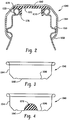
Figure 2 is an enlarged cross-sectional view through the assembled cap on the container. -
Figure 3 shows a cross-sectioned cap in an inverted position (closed end facing upwardly). -
Figure 4 shows the cap ofFigure 3 with the seal material deposited on and inner face of the cap. -
Figure 5 illustrates initial advancement of a tool into the cap. -
Figure 6 shows a cold forming of the seal material on the inner face of the cap. -
Figure 7 shows the final seal profile formed in the cap. -
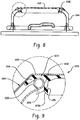
Figure 8 shows the cap rotated through 180° (closed end facing downwardly) from the orientation ofFigure 7 and into threaded engagement with the thread lugs on the container. -
Figure 9 is an enlarged view showing the sealing engagement between the seal and the inner diameter of the container. -
Figure 10 is an illustration of the introduction of individual caps into a seal forming station. -
Figure 11 is an enlarged cross-sectional view of a cap received in sealing engagement with the inner diameter of the container opening. -
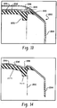
Figure 12 is an enlarged cross-sectional view of a cap that includes a recess, depression, or valley formed in the cap where the cap is received in sealing engagement with a container. -
Figure 13 is an image representing how the seal would engage in inner surface of the container opening under little or no pressure. -
Figure 14 is an image similar toFigure 13 where the sealed container has been pressurized to an elevated level and illustrating how the seal would provide venting. -
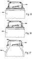
Figure 15 is an elevational view of a cap having the valley with the profiled seal received on a metal container under little or no pressure. -
Figure 16 is an elevational view of a cap having the valley with the profiled seal received on a metal container at an elevated pressure. -
Figure 17 shows the cap and seal on a glass container. - Turning to
Figures 1-11 , this seal arrangement finds particular application in a resealable container assembly 1000 (Figure 1 ) of the type that includes ametal container 1002 closed at a first orlower end 1004, and having asidewall 1006 that connects with a first orupper end 1008 that has anopening 1010. Theopening 1010 receives an associated fluid therethrough, i.e., the fluid is introduced into and poured from thecontainer 1002 through the opening. More particularly, theopening 1010 is located in a reduced diameter region sometimes referred to as a dome that hasneck 1020 formed in themetal container 1002. Thus, in this embodiment thesidewall 1006 of thecontainer 1002 is typically significantly larger in diameter than theopening 1010 in theneck 1020. As shown, theopening 1010 is formed by a curl 1030 (Figure 2 ) shown here as a curl that preferably curves radially outward about 360 degrees, although it will be understood that the curl could also curl inwardly. - A metal cup-shaped
cap 1040 has anend wall 1042, and aperimeter sidewall 1044 extending from the end wall. An inner surface orproduct side 1046 of thecap end wall 1042 is selectively received over theopening 1010 in thecontainer 1002.Lugs 1050 are provided on the cap at spaced perimeter locations of thesidewall 1044, and cooperate withthread lug portions 1060 formed in thedome 1020 of the container. When fully engaged, thethread lug portions 1060 are engaged by the cap lugs 1050 in a manner well known in the industry and retain thecap 1040 on thecontainer 1002 to seal theopening 1010 in the upper end of the container. This assembly of the twist-on/twist-off cap 1040 andcontainer 1002 assembly is in contrast to those container assemblies such as oriented polypropylene assemblies, also referred to as ROPP assemblies, where an unthreaded cap is axially advanced over or received on to the container (not twisted on), and the cap threads and container threads are simultaneously formed in a stamping operation or the threads simultaneously rolled on/off the cap and container. - An
annular seal 1070 is adhered to the inner surface ofend wall 1042 of themetal cap 1040. More particularly, the cup-shapedmetal cap 1040 is typically inverted (Figure 3 ) and the cap heated to raise the temperature of the cap to a level above ambient temperature and aid in adhering the seal material to the cap. For example, the cap may be inductively heated to raise the temperature of the cap between 240° and 400°, and more preferably in the range of 350°-400°. As represented inFigure 4 , while the cap is at an elevated temperature, a predetermined amount ordollop 1072 of seal material is placed in a central region of theinner surface 1046 of thecap end wall 1042. The seal material may be any of a wide range of materials (typically a polymer) suitable for the food industry where polymer beads, for example, are melted (e.g., around 350°) and then extruded to form thedollop 1072 of seal material on theinner surface 1046 of theheated cap 1040. - A
tool assembly 1080 is then introduced into the interior portion of the cap 1040 (Figure 5 ). For example, thetool assembly 1080 may be at ambient i.e., significantly below the elevated temperature of the cap and seal material. A first or inner portion (also referred to as an anvil portion) 1082 of thetool assembly 1080 makes initial contact with thedollop 1072 of seal material. Theentire tool assembly 1080 continues to advance toward thecap 1040 until an outwardly extending portion (also referred to as a seal form tool or gate) 1084 of thesecond portion 1086 of thetool assembly 1080 engages theinner wall surface 1046 of thecap 1040. This engagement (for example, at the bottom of the tool stroke) of theseal form portion 1084 of thetool assembly 1080 with theinner wall 1042 of thecap 1040 limits outward migration of the seal material on the inner wall, and the continued advancement of theanvil portion 1082 relative to theseal form portion 1084 and thecap 1040 presses down on thedollop 1072 and spreads the seal material into a thinner, final profile 1074 (Figures 6-7 ). As will be described more fully below in connection withFigure 10 , the tool assembly remains engaged with the seal material for an extended period of time so that the seal material at least partially cures or sets to an extent that the seal retains the desiredprofile 1074. - More particularly, the
final profile 1074 ofseal 1070 includes a circumferentially continuousfirst region 1076 extending axially outwardly from theinner surface 1046 of the cap 1040 (Figs. 2 and7-9 ). Thefirst region 1076 is dimensioned for engagement within theopening 1010 and thereby seals thecontainer 1002 along the inner diameter (i.e., the innermost diameter) ofcurl 1030. Particularly, thefirst region 1076 has an axial dimension that extends from the product side of thecap 1040 beyond the lowermost edge of thecurl 1030 so that the first region sealingly conforms to the inner curvature of the curl, extending from along the upper edge of theopening 1010 and continuously to the underside, lowermost region of the curl. Further, the shaping of thecontainer 1002 allows the internal pressure in the container to assist in pressure holding capability. As evident inFigures 2 and7-9 , theprofile 1074 of theseal 1070 is configured so that in addition to thefirst region 1076 sealing the inner diameter of the opening 1010 (i.e., the curl 1030), an enlarged,outer shoulder 1078 of the seal engages and seals an upper edge or face of the curl, and also extends radially outward where an angled surface portion of thecap 1040 urges theshoulder 1078 against a radially outer region of the curl. Thus, as shown inFigures 2 and9 , theseal 1070 conforms to the curvature of thecurl 1030 and is sealed along the curl from interiorly of the innermost diameter of the curl that defines the minimal dimension ofopening 1010, and continuously axially and radially outward to an outer portion of the curl (i.e., from approximately 4 o'clock to 10 o'clock as shown in a counterclockwise direction ofFigure 9). Figure 9 also shows in broken line that when the container and fluid content thereof are pressurized (e.g., carbonated beverages are typically pressurized to around 621 kPa (90 psi) for aluminum containers and about 1207 kPa (175 psi) or greater for glass containers), the pressure urges aterminal end 1076A of thefirst region 1076 to further conform to the curvature of thecurl 1030 interiorly of the innermost diameter of the curl, i.e., the first region wraps along the surface of the curl. Further, the seal material extends over theinner wall 1046 of thecap 1040 at a shoulder region orlocation 1078 outwardly of thefirst region 1076. The seal material in thisshoulder region 1078 is not necessarily required for sealing purposes (all sealing is accomplished along the inner diameter of the curl) but provides a desired drag or pressure that alters the on/off torque of thecap 1040 relative to thecontainer 1002. That is, the thicker the layer of seal material, the higher the torque required to close and open thecap 1040 on to thecontainer 1002. As a result of controlling the thickness of the seal material layer, the on/off torque can be controlled at least in part. As a result, the present disclosure provides a twist-on/twist-off cap 1040 having aseal liner 1070 that that seals along the inner diameter of theopening 1010 to retain contents under pressure (around 621 kPa (90 psi) for aluminum or 1207+ kPa (175+ psi) for glass containers), and where the cap can be applied with little on-torque and at a substantially reduced level of down force. Thecap 1040 provides an effective, reliable initial seal with thecontainer 1002 to maintain the contents under pressure, as well as re-sealing the container subsequent to opening. -
Fig. 10 shows aseal forming system 1100 for applying the seal to thecaps 1040. The caps are introduced in an inverted position (e.g., likeFig. 3 ) or product side up at ambientcap feed station 1102. Acap feed screw 1104 advances thecaps 1040 through aheating zone 1106 and to an extruding gun ornozzle 1108 where thedollop 1072 of seal material is located in the central region of theinner wall 1046 of the cap. Atinfeed station 1110, the heated individual caps with dollops of seal material applied thereto are introduced into the rotaryseal forming head 1112 where the seal forming tool assembly 1080 (Figs 5-6 ) forms the desired seal profile as described above. The rotary motion is shown as advancing in a clockwise direction where the dollop of seal material is formed and thetool assembly 1080 remains engaged with thecap 1040 for an extended period of time, i.e., as an individual cap rotates from approximately 4 o'clock as shown to anoutfeed station 1114 where the seal has sufficiently cured to retain the desired final profile once the tool assembly has been removed. -
Fig. 11 is another embodiment of aseal 1200 applied to a modifiedcap 1202 that seals along theinner diameter 1204 of the curl opening. The axially innermost portion of theseal 1200 has a generally planar conformation with a tapered lead-inedge 1206 along an outer perimeter portion to assist in advancing thecap 1202 into position. A central portion orpanel 1208 of thecap 1202 is also recessed or depressed to provide increased strength. Thus, theseal 1200 is still an inside seal much like the previous seal ofFigs. 2-9 except that thecap 1202 is modified to provide the centraldepressed panel 1208 in thecap 1202 to resist the internal pressure because the opening area is substantially larger. Nevertheless, the arrangement still relies on the inner diameter or side seal for holding pressure. Theseal 1200 is radially positioned between thecentral panel 1208 of the cap and the opening in the container. - The chart below illustrates the versatility of the present disclosure, showing various cap sizes that advantageously achieve an effective seal with the container along the inner diameter opening of the curl as disclosed herein (represented in the second column as the held seal pressure) with a minimum of on-torque required to twist the cap on to the container.
Cap Diameter kPa (Psi) On-Torque Top Load Pressure/Force 28 mm 689 (100) 0.3 Nm (3 in-lbs) and up < 32 kg (< 70 lbs) 41 621 (90) 0.3 Nm (3 in-lbs) and up < 32 kg (<70 lbs) 52 621 (90) 2.5 Nm (22 in-lbs) < 32 kg (< 70 lbs) - In summary, the container is preferably sealed along the inner diameter interface between the cap seal and a curl on the container. The seal extends from the metal cap and is formed to extend beyond a lowermost part of the curl so that pressure inside of the container can enhance the seal along the "underside" of the inner diameter of the curl. In particular, the metal cap can be twisted on to a container and forms an effective seal (as opposed to being received on a container and the cap being stamped or deformed to create the threaded arrangement between the cap and container). The on-torque is preferably sufficiently low, e.g. 5.6 Nm (50 inch-pounds) or less, and more preferably 0.3-4.0 Nm (3-35 inch-pounds) or less for cap diameters ranging from 28 mm to 52 mm (see chart above) while applying the cap. Some drag torque may be desired to keep the containers from twisting while making the seal with the inner diameter of the container. Thus, the seal material at the top is only used to control the drag force since all sealing between the cap and container occurs at the inner diameter opening of the container. When the cap is tilted relative to the container, it may be possible to vent past the extended length of the seal if so desired. Moreover, the preferred design uses minimal downforce (e.g., less than 45 kg (100 pounds), and more preferably less than 32 kg (70 pounds)) on the metal cap to achieve a seal with the container without using steam to soften or make the seal more slick.
- It is also contemplated that this feature of sealing along the inner diameter interface between the cap seal and the container seal could find application in connection with ROPP, and thereby result in a substantial reduction in down force used during the ROPP process (e.g., about 45 kg (100 pounds) or less of down force imposed on the cap during the roll on process).
- Moreover, the seal is effective at elevated temperatures such as encountered in pasteurization, and the seal is enhanced during the temperature rise and increased pressure as a result of the lip of the seal extending beyond a lowermost part of the container curl to enhance the seal along the underside of the inner diameter of the curl.
- Although not necessary for an effective seal for all of the reasons noted above in connection with the inner diameter seal formed with the container curl, the outside 1078 of the cap 1042 (
Figure 9 ) can also add to the seal and the threads of the cap and container cooperate to apply the desired force that seals in these regions. - Turning to
Figures 12 - 17 , there are two dimensions "A" and "B" of the profiledseal 2070 that can be selectively altered or changed to determine the amount of pressure being held by thecap 2040 when the cap is received on thecontainer assembly 2000. More specifically, dimension "A" relates to the outer dimension or diameter of theseal 2070, and more specifically relates to that portion of the profiled seal that extends axially into thecontainer opening 2010 and sealingly engages with the inner perimeter of theopening 2010. Increasing or decreasing the dimension A alters the amount of compression and thus determines whether more or less pressure is held by thecontainer 2002 with thecap 2040 in place. If the diameter or A dimension is increased, the holding pressure of the cap is likewise increased. In one example, the diameter was increased by 0.508 mm (0.020 inches) and resulted in the holding pressure being increased from 931 kPa (135 psi) to 1379 kPa (200 psi). Of course these dimensions and pressures are representative only. - Alternatively, the B dimension can be changed. For example, shortening the B dimension which represents the dimension of the
first region 2076 of the profiled seal protruding from the inner surface of thecap 2040 reduces the amount of pressure that the container can hold. This results because thefirst region 2076 of the profiledseal 2070 is not long enough to wrap around and underneath the curl of thecontainer opening 2010. Alternatively, lengthening the dimension B generally increases the amount of pressure that thecontainer 2010 can hold. - A depression, valley, recess, or
deformation 2090 is provided in theend wall 2042 of thecap 2040. Thedepression 2090 is formed in theend wall 2042 at a location spaced inwardly from thesidewall 2044 of thecap 2040. Thedepression 2090 is preferably circumferentially continuous and generally aligns with the axially extendingfirst region 2076 of the profiled seal. Adding thedepression 2090 to theend wall 2042 eliminates variation and provides for a stiffer central panel of the cap end wall. The depression also serves as a pivot when the outer panel rises as a result of increased internal pressure. As a result of this increased pressure and resultant pivoting action, thefirst region 2076 of the profiledseal 2070 is drawn away from theopening 2010 in the container. This allows the container to vent. As will be appreciated, the manufacturer would like to control the level at which the container vents. Thus, altering the dimension A determines the maximum pressure that can be held by the cap, for example, approximately 621 kPa (90 psi) is desired for metal/aluminum containers and in other instances approximately 1207 kPa (175 psi) or greater is required for a glass container. Once again, these are representative examples only and should not be deemed to limit the present disclosure. - In some instances, it may also be desirable to remove a portion of the
seal material 2070 in the region 2092 (Figure 12 ). This removed material in theregion 2092 above the apex of the curl of the container that forms theopening 2010 can reduce the on-torque required to assemble thecap 2040 to thecontainer 2002. - This written description uses examples to describe the disclosure, including the best mode, and also to enable any person skilled in the art to make and use the disclosure. The patentable scope of the disclosure is defined by the claims, and may include other examples that occur to those skilled in the art.
Claims (15)
- A resealable container assembly (1000) comprising:a metal container (1002) that is closed at a first end (1004) so as to be configured for holding an associated fluid at a pressure of at least 621 kPa (90 psi) therein, and having an opening (1010) at a second end (1008), the opening having an inner diameter through which the associated fluid is introduced into and poured from the container (1002), the container (1002) having thread portions (1060) adjacent the second end (1008) along an external surface thereof;a metal cup-shaped cap (1040) having an end wall (1042), and a perimeter sidewall (1044) extending from the end wall (1042), wherein the cap (1040) includes one of (i) roll on pilfer proof thread portions, or (ii) circumferentially spaced lugs (1050), the roll on pilfer proof thread portions or lugs (1050) dimensioned for selective twist-on/twist-off receipt relative to the thread portions (1060) of the container (1002); anda seal (1070) adhered to an inner surface (1046) of the end wall (1042) of the cap (1040),characterized in that the seal includes a continuous axial region (1076) extending outwardly from the cap end wall (1042) a larger extent than a remainder of the seal (1070), the axial region (1076) of the seal (1070) having a radially outer, external surface dimensioned and configured for sealing engagement with a smallest inner diameter of the container opening (1010), such that the external surface of the axial region (1076) seals the container (1002) along the smallest inner diameter of the container opening (1010), whereby the seal formed between the axial region (1076) and the smallest inner diameter of the container opening (1010) maintains the associated fluid within the container (1002) at pressure (i) while holding the cap (1040) on the container (1002) with less than 45 kg (100 pounds) of down force during formation of the roll on pilfer proof thread portions, or (ii) when the cap is twisted to place the circumferentially spaced lugs (1050) into threaded engagement with the container (1002) using an on-torque value measured in newton-meters that is less than 0.0565 times a diameter of the cap (1040) measured in millimeters (using an on-torque value measured in inch-pounds that is less than one-half a diameter of the cap (1040) measured in millimeters).
- The container assembly (1000) of claim 1 wherein the container (1002) includes a curl (1030) at the second end (1008) to form the opening (1010), the curl (1030) defining an apex portion of the container opening (1010).
- The container assembly (1000) of claim 2 wherein the seal (1070) includes a shoulder region (1078) adjacent an interface of the axial region (1076) with the end wall (1042) of the cap (1040), the shoulder region (1078) dimensioned for engagement along the apex portion.
- The container assembly (1000) of claim 3 wherein the engagement of the shoulder region (1078) along the apex portion controls drag forces generated when the cap (1040) is moved relative to the container (1002) rather than sealing the pressure of the associated fluid within the container (1002), which is performed solely by the seal formed between the axial region (1076) in the smallest inner diameter of the container opening (1010).
- The container assembly (1000) of claim 1 wherein the seal formed between the axial region (1076) and the smallest inner diameter of the container opening (1010) maintains the associated fluid within the container (1002) at pressure when less than 32 kg (70 pounds) of down force is used during formation of the roll on pilfer proof thread portions.
- The container assembly (1000) of claim 1 wherein the on-torque maximum value used when the cap (1040) having circumferentially spaced lugs (1050) is twisted into threaded engagement with the container (1002) is between 0.34 Nm (3 inch-pounds) and a value in newton-meters that is less than 0.0565 times the diameter of the cap (1040) measured in millimeters (a value in inch-pounds that is less than one-half the diameter of the cap (1040) measured in millimeters).
- The container assembly (1000) of claim 6, wherein the seal (1070) formed between the axial region (1076) and the smallest inner diameter of the container opening (1010) maintains the associated fluid within the container (1002) at pressure when the cap (1040) with circumferentially spaced lugs (1050) is twisted into threaded engagement with the container (1002) with a down force applied of less than 32 kg (70 pounds).
- A process of assembling a metal cap (1040) and a metal container (1002) so as to seal an associated fluid therein under pressure, the process comprising:providing a metal cap (1040) having an end wall (1042) with an inner surface (1046);providing a metal container (1002) that is closed at a first end (1004) and having an opening (1010) with thread portions (1060) at a second end (1008);providing a seal (1070) on the metal cap (1040) that extends outwardly therefrom for sealing engagement with an innermost diameter of the opening (1010), including (i) providing a continuous axial region (1076) extending outwardly from the cap inner surface (1046) a larger extent than a remainder of the seal (1070), and (ii) dimensioning and configuring the axial region (1076) of the seal (1070) to have a radially outer, external surface dimensioned and configured for sealing engagement with a smallest inner diameter of the container opening (1010);installing the cap (1040) on the container such that the sealing engagement is formed between the axial region (1076) and the smallest inner diameter of the container opening (1010), the sealing engagement configured to hold the associated fluid at a pressure of at least 621 kPa (90 psi); andone of (i) forming roll on pilfer proof thread portions on the cap (1040) while the cap (1040) is held on the container (1002) with less than 45 kg (100 pounds) of down force during formation of the roll on pilfer proof thread portions and the sealing engagement of the axial region (1076) with the smallest inner diameter of the container opening (1010) maintains the associated fluid within the container (1002) at pressure during the formation of the roll on pilfer proof thread portions, or (ii) providing circumferentially spaced lugs (1050) on the metal cap (1040) that cooperate with the container thread portions (1060) for selective twist-on/twist-off receipt of the lugged metal cap (1040) relative to the thread portions (1060) on the container (1002) with an on-torque maximum value used when the cap (1040) is twisted into threaded engagement with the container (1002) at a value measured in newton-meters less than 0.0565 times a diameter of the cap (1040) measured in millimeters (at a value measured in inch-pounds less than one-half a diameter of the cap (1040) measured in millimeters) to maintain the associated fluid within the container at pressure.
- The process of claim 8 further comprising providing a shoulder region (1078) of the seal (1070) disposed radially outward of an interface of the axial region (1076) with the inner surface (1046) of the end wall (1042) of the cap (1040), and dimensioning the shoulder region (1078) for engagement along an apex portion of the container opening (1010) and terminating adjacent the apex portion and radially inward of an outermost diameter of the second end (1008) of the container (1002).
- The process of claim 8 wherein the seal forming step includes dimensioning the seal (1070) to have an axial length that extends axially inward of the innermost diameter of the opening (1010).
- The process of claim 8 further comprising placing a dollop (1072) of seal material in a central region of the inner surface (1046) of the cap (1040);
engaging the cap inner surface (1046) with a tool (1080) that forms a seal around a perimeter of the dollop of seal material; and
providing a desired profile of the seal material on the inner surface (1046) of the metal cap (1040). - The process of claim 8 further comprising twisting the cap (1040) with circumferentially spaced lugs (1050) on to the container (1002) with an on-torque maximum value measured at a value between 0.34 Nm (3 inch-pounds) and a value measured in newton-meters that is less than 0.0565 times the diameter of the cap (1040) measured in millimeters (a value measured in inch-pounds that is less than one-half the diameter of the cap (1040) measured in millimeters).
- The process of claim 12 further comprising applying the cap (1040) to the container (1002) with less than 32 kg (70 pounds) of down force to seal the cap (1040) to the container (1002) while holding the associated fluid within the container (1002) under pressure.
- The process of claim 8 further comprising including a shoulder region (1078) adjacent an interface of the axial region (1076) with an end wall (1042) of the cap (1040), the shoulder region (1078) dimensioned for engagement along an apex portion of the container opening (1010), and generating drag forces when the cap (1040) is moved relative to the container (1002) rather than sealing the pressure of the associated fluid within the container (1002), which is performed solely by the seal formed between the axial region (1076) and the smallest inner diameter of the container opening (1010).
- The process of claim 8 further comprising applying the cap (1040) to the container (1002) with less than 32 kg (70 pounds) of down force to seal the cap (1040) to the container (1002) while holding the associated fluid within the container (1002) under pressure.
Priority Applications (1)
| Application Number | Priority Date | Filing Date | Title |
|---|---|---|---|
| PL15842003T PL3194284T3 (en) | 2014-09-16 | 2015-09-16 | Cap assembly having inside seal |
Applications Claiming Priority (3)
| Application Number | Priority Date | Filing Date | Title |
|---|---|---|---|
| US201462051213P | 2014-09-16 | 2014-09-16 | |
| US201562136847P | 2015-03-23 | 2015-03-23 | |
| PCT/US2015/050491 WO2016044460A1 (en) | 2014-09-16 | 2015-09-16 | Cap assembly having inside seal |
Publications (3)
| Publication Number | Publication Date |
|---|---|
| EP3194284A1 EP3194284A1 (en) | 2017-07-26 |
| EP3194284A4 EP3194284A4 (en) | 2018-04-18 |
| EP3194284B1 true EP3194284B1 (en) | 2020-01-01 |
Family
ID=55533804
Family Applications (1)
| Application Number | Title | Priority Date | Filing Date |
|---|---|---|---|
| EP15842003.4A Active EP3194284B1 (en) | 2014-09-16 | 2015-09-16 | Cap assembly having inside seal |
Country Status (10)
| Country | Link |
|---|---|
| US (3) | US9676524B2 (en) |
| EP (1) | EP3194284B1 (en) |
| JP (1) | JP6784678B2 (en) |
| CN (1) | CN107148386B (en) |
| AU (1) | AU2015317738B2 (en) |
| CA (1) | CA2961494C (en) |
| ES (1) | ES2769855T3 (en) |
| MX (1) | MX2017003542A (en) |
| PL (1) | PL3194284T3 (en) |
| WO (1) | WO2016044460A1 (en) |
Families Citing this family (15)
| Publication number | Priority date | Publication date | Assignee | Title |
|---|---|---|---|---|
| US11952164B1 (en) | 2012-08-10 | 2024-04-09 | Powercan Holding, Llc | Resealable container lid and accessories including methods of manufacture and use |
| US10093460B2 (en) | 2015-08-14 | 2018-10-09 | Yeti Coolers, Llc | Container with magnetic cap |
| USD787893S1 (en) | 2015-11-20 | 2017-05-30 | Yeti Coolers, Llc | Jug |
| US10959552B2 (en) | 2016-10-17 | 2021-03-30 | Yeti Coolers, Llc | Container and method of forming a container |
| CA3040708A1 (en) | 2016-10-17 | 2018-04-26 | John Alan Tolman | Container and method of forming a container |
| US10959553B2 (en) | 2016-10-17 | 2021-03-30 | Yeti Coolers, Llc | Container and method of forming a container |
| US11034505B2 (en) | 2016-10-17 | 2021-06-15 | Yeti Coolers, Llc | Container and method of forming a container |
| USD860716S1 (en) | 2017-03-27 | 2019-09-24 | Yeti Coolers, Llc | Container lid |
| CN110615174B (en) * | 2018-06-19 | 2022-05-06 | 义乌市易开盖实业公司 | Packaging container with safety reminding structure |
| USD896572S1 (en) | 2018-08-20 | 2020-09-22 | Yeti Coolers, Llc | Container lid |
| USD871133S1 (en) | 2018-10-17 | 2019-12-31 | Yeti Coolers, Llc | Lid |
| USD883737S1 (en) | 2018-10-17 | 2020-05-12 | Yeti Coolers, Llc | Lid |
| USD897151S1 (en) | 2018-10-17 | 2020-09-29 | Yeti Coolers, Llc | Lid |
| USD883738S1 (en) | 2018-10-17 | 2020-05-12 | Yeti Coolers, Llc | Lid |
| CN114082744B (en) * | 2021-11-15 | 2023-02-07 | 烟台华正医疗器械科技有限公司 | Foreign matter removing apparatus for composite cover |
Citations (1)
| Publication number | Priority date | Publication date | Assignee | Title |
|---|---|---|---|---|
| US20060169665A1 (en) * | 2003-02-28 | 2006-08-03 | Daiwa Can Company | Metal pilfer-proof cap |
Family Cites Families (23)
| Publication number | Priority date | Publication date | Assignee | Title |
|---|---|---|---|---|
| US888818A (en) * | 1906-11-05 | 1908-05-26 | Julius Karrmann | Closure for jars, bottles, and the like. |
| US1972280A (en) * | 1930-07-18 | 1934-09-04 | Anchor Cap & Closure Corp | Sealed package |
| BE636571A (en) * | 1962-12-22 | |||
| US3411649A (en) * | 1966-09-19 | 1968-11-19 | Owens Illinois Inc | Closure for reducing heat transfer to product during processing |
| US3450291A (en) * | 1966-11-29 | 1969-06-17 | Walter C Lovell | Bottle caps |
| JPS5520126A (en) * | 1978-07-22 | 1980-02-13 | Crown Cork Japan | Container cover with liner and method of producing same |
| JPH0637222B2 (en) * | 1985-12-04 | 1994-05-18 | 喜多産業株式会社 | Container lid with liner and method of manufacturing the same |
| JPH04339772A (en) * | 1991-05-09 | 1992-11-26 | Toyo Seikan Kaisha Ltd | Container lid with liner and production thereof |
| US5622280A (en) * | 1995-07-06 | 1997-04-22 | North American Packaging Company | Method and apparatus for sealing an open head drum |
| US6015062A (en) * | 1997-11-17 | 2000-01-18 | Dayton Systems Group, Inc. | Resealable beverage container and top therefor |
| JP2004083128A (en) * | 2001-12-28 | 2004-03-18 | Mitsubishi Materials Corp | Bottle can body and bottle |
| AU2003247736A1 (en) * | 2002-06-26 | 2004-01-19 | Dayton Systems Group, Inc. | Container and closure |
| JP2004175388A (en) * | 2002-11-26 | 2004-06-24 | Alcoa Closure Systems Japan Ltd | Cap, closing device, and beverage filled in container |
| JP4382372B2 (en) * | 2003-02-17 | 2009-12-09 | 大和製罐株式会社 | Molding method of sealing liner |
| JP4503308B2 (en) * | 2004-02-13 | 2010-07-14 | 日本クラウンコルク株式会社 | Container lid for sheet metal container |
| JP4307347B2 (en) * | 2004-08-20 | 2009-08-05 | 東洋製罐株式会社 | Metal cap winding container and metal cap winding method of container |
| US20080190882A1 (en) * | 2005-04-28 | 2008-08-14 | Matthew Eric Smith | Beverage Containers |
| JP4925158B2 (en) * | 2005-08-19 | 2012-04-25 | 大和製罐株式会社 | Structure of resin liner for cap |
| US9957076B2 (en) * | 2008-01-15 | 2018-05-01 | Rexam Beverage Can Company | Outsert for a metal container |
| US8496131B2 (en) * | 2008-10-21 | 2013-07-30 | Rexam Beverage Can Company | Cap for a lug-type closure |
| WO2010099566A1 (en) * | 2009-03-02 | 2010-09-10 | Manfred Imand Kurmis | A sealing member for a closure |
| JP5414616B2 (en) * | 2010-05-14 | 2014-02-12 | ユニバーサル製缶株式会社 | Metal cap and bottle with cap |
| CN103298704B (en) * | 2010-12-23 | 2016-08-24 | M·I·克尔梅斯 | Black box for closure member |
-
2015
- 2015-09-16 ES ES15842003T patent/ES2769855T3/en active Active
- 2015-09-16 MX MX2017003542A patent/MX2017003542A/en unknown
- 2015-09-16 PL PL15842003T patent/PL3194284T3/en unknown
- 2015-09-16 CN CN201580061003.9A patent/CN107148386B/en active Active
- 2015-09-16 EP EP15842003.4A patent/EP3194284B1/en active Active
- 2015-09-16 CA CA2961494A patent/CA2961494C/en active Active
- 2015-09-16 WO PCT/US2015/050491 patent/WO2016044460A1/en active Application Filing
- 2015-09-16 AU AU2015317738A patent/AU2015317738B2/en active Active
- 2015-09-16 JP JP2017534898A patent/JP6784678B2/en active Active
-
2016
- 2016-05-04 US US15/146,658 patent/US9676524B2/en active Active
-
2017
- 2017-04-14 US US15/487,976 patent/US9821931B2/en active Active
- 2017-10-25 US US15/793,017 patent/US10214323B2/en active Active
Patent Citations (1)
| Publication number | Priority date | Publication date | Assignee | Title |
|---|---|---|---|---|
| US20060169665A1 (en) * | 2003-02-28 | 2006-08-03 | Daiwa Can Company | Metal pilfer-proof cap |
Also Published As
| Publication number | Publication date |
|---|---|
| US20170217645A1 (en) | 2017-08-03 |
| US9821931B2 (en) | 2017-11-21 |
| BR112017005281A2 (en) | 2018-11-06 |
| US10214323B2 (en) | 2019-02-26 |
| JP2017532265A (en) | 2017-11-02 |
| AU2015317738A1 (en) | 2017-05-04 |
| AU2015317738B2 (en) | 2020-05-21 |
| CN107148386A (en) | 2017-09-08 |
| ES2769855T3 (en) | 2020-06-29 |
| JP6784678B2 (en) | 2020-11-11 |
| PL3194284T3 (en) | 2020-05-18 |
| US20160244213A1 (en) | 2016-08-25 |
| CN107148386B (en) | 2020-11-24 |
| CA2961494C (en) | 2022-12-13 |
| US9676524B2 (en) | 2017-06-13 |
| EP3194284A4 (en) | 2018-04-18 |
| MX2017003542A (en) | 2017-12-11 |
| EP3194284A1 (en) | 2017-07-26 |
| CA2961494A1 (en) | 2016-03-24 |
| WO2016044460A1 (en) | 2016-03-24 |
| US20180044071A1 (en) | 2018-02-15 |
Similar Documents
| Publication | Publication Date | Title |
|---|---|---|
| EP3194284B1 (en) | Cap assembly having inside seal | |
| US10040608B2 (en) | Metal bottle seal | |
| EP1247750B1 (en) | Metal container with thread | |
| US3868038A (en) | Closures for containers | |
| US20180370694A1 (en) | Method of forming a metal closure and closure for container | |
| JP2011037497A (en) | Metal cap with liner, manufacturing method of the same, container with cap, and manufacturing method of the same | |
| US2979218A (en) | Closure cap and sealed package | |
| US20080283486A1 (en) | Closure for a Container, Especially a Bottle | |
| US4356680A (en) | Method of applying closures to containers | |
| US2974816A (en) | Closing and sealing bottles and other receptacles | |
| JP4201264B2 (en) | Capping method and apparatus | |
| US20160107802A1 (en) | Second generation low gauge crown cap | |
| BR112017005281B1 (en) | REUSABLE CONTAINER ASSEMBLY AND FORMATION PROCESS OF A METAL LID AND A METAL CONTAINER ASSEMBLY | |
| WO1998009879A1 (en) | Wine bottle and closure | |
| AU3934497A (en) | Wine bottle and closure |
Legal Events
| Date | Code | Title | Description |
|---|---|---|---|
| STAA | Information on the status of an ep patent application or granted ep patent |
Free format text: STATUS: THE INTERNATIONAL PUBLICATION HAS BEEN MADE |
|
| PUAI | Public reference made under article 153(3) epc to a published international application that has entered the european phase |
Free format text: ORIGINAL CODE: 0009012 |
|
| STAA | Information on the status of an ep patent application or granted ep patent |
Free format text: STATUS: REQUEST FOR EXAMINATION WAS MADE |
|
| 17P | Request for examination filed |
Effective date: 20170322 |
|
| AK | Designated contracting states |
Kind code of ref document: A1 Designated state(s): AL AT BE BG CH CY CZ DE DK EE ES FI FR GB GR HR HU IE IS IT LI LT LU LV MC MK MT NL NO PL PT RO RS SE SI SK SM TR |
|
| AX | Request for extension of the european patent |
Extension state: BA ME |
|
| DAV | Request for validation of the european patent (deleted) | ||
| DAX | Request for extension of the european patent (deleted) | ||
| REG | Reference to a national code |
Ref country code: DE Ref legal event code: R079 Ref document number: 602015044872 Country of ref document: DE Free format text: PREVIOUS MAIN CLASS: B65D0041040000 Ipc: B65D0053040000 |
|
| A4 | Supplementary search report drawn up and despatched |
Effective date: 20180321 |
|
| RIC1 | Information provided on ipc code assigned before grant |
Ipc: B65D 81/20 20060101ALI20180315BHEP Ipc: B65D 41/04 20060101ALI20180315BHEP Ipc: B65D 53/04 20060101AFI20180315BHEP Ipc: B65D 41/34 20060101ALI20180315BHEP |
|
| GRAP | Despatch of communication of intention to grant a patent |
Free format text: ORIGINAL CODE: EPIDOSNIGR1 |
|
| STAA | Information on the status of an ep patent application or granted ep patent |
Free format text: STATUS: GRANT OF PATENT IS INTENDED |
|
| INTG | Intention to grant announced |
Effective date: 20190621 |
|
| GRAS | Grant fee paid |
Free format text: ORIGINAL CODE: EPIDOSNIGR3 |
|
| GRAA | (expected) grant |
Free format text: ORIGINAL CODE: 0009210 |
|
| STAA | Information on the status of an ep patent application or granted ep patent |
Free format text: STATUS: THE PATENT HAS BEEN GRANTED |
|
| RAP1 | Party data changed (applicant data changed or rights of an application transferred) |
Owner name: DSG TECHNOLOGY LLC |
|
| AK | Designated contracting states |
Kind code of ref document: B1 Designated state(s): AL AT BE BG CH CY CZ DE DK EE ES FI FR GB GR HR HU IE IS IT LI LT LU LV MC MK MT NL NO PL PT RO RS SE SI SK SM TR |
|
| REG | Reference to a national code |
Ref country code: GB Ref legal event code: FG4D |
|
| REG | Reference to a national code |
Ref country code: CH Ref legal event code: EP Ref country code: CH Ref legal event code: NV Representative=s name: NOVAGRAAF INTERNATIONAL SA, CH Ref country code: AT Ref legal event code: REF Ref document number: 1219538 Country of ref document: AT Kind code of ref document: T Effective date: 20200115 |
|
| REG | Reference to a national code |
Ref country code: IE Ref legal event code: FG4D |
|
| REG | Reference to a national code |
Ref country code: DE Ref legal event code: R096 Ref document number: 602015044872 Country of ref document: DE |
|
| REG | Reference to a national code |
Ref country code: NL Ref legal event code: MP Effective date: 20200101 |
|
| REG | Reference to a national code |
Ref country code: ES Ref legal event code: FG2A Ref document number: 2769855 Country of ref document: ES Kind code of ref document: T3 Effective date: 20200629 |
|
| REG | Reference to a national code |
Ref country code: LT Ref legal event code: MG4D |
|
| PG25 | Lapsed in a contracting state [announced via postgrant information from national office to epo] |
Ref country code: LT Free format text: LAPSE BECAUSE OF FAILURE TO SUBMIT A TRANSLATION OF THE DESCRIPTION OR TO PAY THE FEE WITHIN THE PRESCRIBED TIME-LIMIT Effective date: 20200101 Ref country code: RS Free format text: LAPSE BECAUSE OF FAILURE TO SUBMIT A TRANSLATION OF THE DESCRIPTION OR TO PAY THE FEE WITHIN THE PRESCRIBED TIME-LIMIT Effective date: 20200101 Ref country code: NO Free format text: LAPSE BECAUSE OF FAILURE TO SUBMIT A TRANSLATION OF THE DESCRIPTION OR TO PAY THE FEE WITHIN THE PRESCRIBED TIME-LIMIT Effective date: 20200401 Ref country code: FI Free format text: LAPSE BECAUSE OF FAILURE TO SUBMIT A TRANSLATION OF THE DESCRIPTION OR TO PAY THE FEE WITHIN THE PRESCRIBED TIME-LIMIT Effective date: 20200101 Ref country code: CZ Free format text: LAPSE BECAUSE OF FAILURE TO SUBMIT A TRANSLATION OF THE DESCRIPTION OR TO PAY THE FEE WITHIN THE PRESCRIBED TIME-LIMIT Effective date: 20200101 Ref country code: NL Free format text: LAPSE BECAUSE OF FAILURE TO SUBMIT A TRANSLATION OF THE DESCRIPTION OR TO PAY THE FEE WITHIN THE PRESCRIBED TIME-LIMIT Effective date: 20200101 Ref country code: PT Free format text: LAPSE BECAUSE OF FAILURE TO SUBMIT A TRANSLATION OF THE DESCRIPTION OR TO PAY THE FEE WITHIN THE PRESCRIBED TIME-LIMIT Effective date: 20200527 |
|
| PG25 | Lapsed in a contracting state [announced via postgrant information from national office to epo] |
Ref country code: HR Free format text: LAPSE BECAUSE OF FAILURE TO SUBMIT A TRANSLATION OF THE DESCRIPTION OR TO PAY THE FEE WITHIN THE PRESCRIBED TIME-LIMIT Effective date: 20200101 Ref country code: GR Free format text: LAPSE BECAUSE OF FAILURE TO SUBMIT A TRANSLATION OF THE DESCRIPTION OR TO PAY THE FEE WITHIN THE PRESCRIBED TIME-LIMIT Effective date: 20200402 Ref country code: BG Free format text: LAPSE BECAUSE OF FAILURE TO SUBMIT A TRANSLATION OF THE DESCRIPTION OR TO PAY THE FEE WITHIN THE PRESCRIBED TIME-LIMIT Effective date: 20200401 Ref country code: LV Free format text: LAPSE BECAUSE OF FAILURE TO SUBMIT A TRANSLATION OF THE DESCRIPTION OR TO PAY THE FEE WITHIN THE PRESCRIBED TIME-LIMIT Effective date: 20200101 Ref country code: SE Free format text: LAPSE BECAUSE OF FAILURE TO SUBMIT A TRANSLATION OF THE DESCRIPTION OR TO PAY THE FEE WITHIN THE PRESCRIBED TIME-LIMIT Effective date: 20200101 Ref country code: IS Free format text: LAPSE BECAUSE OF FAILURE TO SUBMIT A TRANSLATION OF THE DESCRIPTION OR TO PAY THE FEE WITHIN THE PRESCRIBED TIME-LIMIT Effective date: 20200501 |
|
| REG | Reference to a national code |
Ref country code: DE Ref legal event code: R097 Ref document number: 602015044872 Country of ref document: DE |
|
| PG25 | Lapsed in a contracting state [announced via postgrant information from national office to epo] |
Ref country code: RO Free format text: LAPSE BECAUSE OF FAILURE TO SUBMIT A TRANSLATION OF THE DESCRIPTION OR TO PAY THE FEE WITHIN THE PRESCRIBED TIME-LIMIT Effective date: 20200101 Ref country code: SK Free format text: LAPSE BECAUSE OF FAILURE TO SUBMIT A TRANSLATION OF THE DESCRIPTION OR TO PAY THE FEE WITHIN THE PRESCRIBED TIME-LIMIT Effective date: 20200101 Ref country code: DK Free format text: LAPSE BECAUSE OF FAILURE TO SUBMIT A TRANSLATION OF THE DESCRIPTION OR TO PAY THE FEE WITHIN THE PRESCRIBED TIME-LIMIT Effective date: 20200101 Ref country code: SM Free format text: LAPSE BECAUSE OF FAILURE TO SUBMIT A TRANSLATION OF THE DESCRIPTION OR TO PAY THE FEE WITHIN THE PRESCRIBED TIME-LIMIT Effective date: 20200101 Ref country code: EE Free format text: LAPSE BECAUSE OF FAILURE TO SUBMIT A TRANSLATION OF THE DESCRIPTION OR TO PAY THE FEE WITHIN THE PRESCRIBED TIME-LIMIT Effective date: 20200101 |
|
| PLBE | No opposition filed within time limit |
Free format text: ORIGINAL CODE: 0009261 |
|
| STAA | Information on the status of an ep patent application or granted ep patent |
Free format text: STATUS: NO OPPOSITION FILED WITHIN TIME LIMIT |
|
| REG | Reference to a national code |
Ref country code: AT Ref legal event code: MK05 Ref document number: 1219538 Country of ref document: AT Kind code of ref document: T Effective date: 20200101 |
|
| 26N | No opposition filed |
Effective date: 20201002 |
|
| PG25 | Lapsed in a contracting state [announced via postgrant information from national office to epo] |
Ref country code: AT Free format text: LAPSE BECAUSE OF FAILURE TO SUBMIT A TRANSLATION OF THE DESCRIPTION OR TO PAY THE FEE WITHIN THE PRESCRIBED TIME-LIMIT Effective date: 20200101 Ref country code: IT Free format text: LAPSE BECAUSE OF FAILURE TO SUBMIT A TRANSLATION OF THE DESCRIPTION OR TO PAY THE FEE WITHIN THE PRESCRIBED TIME-LIMIT Effective date: 20200101 |
|
| PG25 | Lapsed in a contracting state [announced via postgrant information from national office to epo] |
Ref country code: SI Free format text: LAPSE BECAUSE OF FAILURE TO SUBMIT A TRANSLATION OF THE DESCRIPTION OR TO PAY THE FEE WITHIN THE PRESCRIBED TIME-LIMIT Effective date: 20200101 |
|
| PG25 | Lapsed in a contracting state [announced via postgrant information from national office to epo] |
Ref country code: MC Free format text: LAPSE BECAUSE OF FAILURE TO SUBMIT A TRANSLATION OF THE DESCRIPTION OR TO PAY THE FEE WITHIN THE PRESCRIBED TIME-LIMIT Effective date: 20200101 |
|
| PG25 | Lapsed in a contracting state [announced via postgrant information from national office to epo] |
Ref country code: LU Free format text: LAPSE BECAUSE OF NON-PAYMENT OF DUE FEES Effective date: 20200916 |
|
| PG25 | Lapsed in a contracting state [announced via postgrant information from national office to epo] |
Ref country code: IE Free format text: LAPSE BECAUSE OF NON-PAYMENT OF DUE FEES Effective date: 20200916 |
|
| PG25 | Lapsed in a contracting state [announced via postgrant information from national office to epo] |
Ref country code: TR Free format text: LAPSE BECAUSE OF FAILURE TO SUBMIT A TRANSLATION OF THE DESCRIPTION OR TO PAY THE FEE WITHIN THE PRESCRIBED TIME-LIMIT Effective date: 20200101 Ref country code: MT Free format text: LAPSE BECAUSE OF FAILURE TO SUBMIT A TRANSLATION OF THE DESCRIPTION OR TO PAY THE FEE WITHIN THE PRESCRIBED TIME-LIMIT Effective date: 20200101 Ref country code: CY Free format text: LAPSE BECAUSE OF FAILURE TO SUBMIT A TRANSLATION OF THE DESCRIPTION OR TO PAY THE FEE WITHIN THE PRESCRIBED TIME-LIMIT Effective date: 20200101 |
|
| PG25 | Lapsed in a contracting state [announced via postgrant information from national office to epo] |
Ref country code: MK Free format text: LAPSE BECAUSE OF FAILURE TO SUBMIT A TRANSLATION OF THE DESCRIPTION OR TO PAY THE FEE WITHIN THE PRESCRIBED TIME-LIMIT Effective date: 20200101 Ref country code: AL Free format text: LAPSE BECAUSE OF FAILURE TO SUBMIT A TRANSLATION OF THE DESCRIPTION OR TO PAY THE FEE WITHIN THE PRESCRIBED TIME-LIMIT Effective date: 20200101 |
|
| PGFP | Annual fee paid to national office [announced via postgrant information from national office to epo] |
Ref country code: GB Payment date: 20230810 Year of fee payment: 9 |
|
| PGFP | Annual fee paid to national office [announced via postgrant information from national office to epo] |
Ref country code: PL Payment date: 20230808 Year of fee payment: 9 Ref country code: FR Payment date: 20230808 Year of fee payment: 9 Ref country code: DE Payment date: 20230808 Year of fee payment: 9 Ref country code: BE Payment date: 20230809 Year of fee payment: 9 |
|
| PGFP | Annual fee paid to national office [announced via postgrant information from national office to epo] |
Ref country code: ES Payment date: 20231011 Year of fee payment: 9 |
|
| PGFP | Annual fee paid to national office [announced via postgrant information from national office to epo] |
Ref country code: CH Payment date: 20231001 Year of fee payment: 9 |