EP3193495A1 - Information device control method and program - Google Patents
Information device control method and program Download PDFInfo
- Publication number
- EP3193495A1 EP3193495A1 EP14878398.8A EP14878398A EP3193495A1 EP 3193495 A1 EP3193495 A1 EP 3193495A1 EP 14878398 A EP14878398 A EP 14878398A EP 3193495 A1 EP3193495 A1 EP 3193495A1
- Authority
- EP
- European Patent Office
- Prior art keywords
- room
- display
- screen
- subject
- list screen
- Prior art date
- Legal status (The legal status is an assumption and is not a legal conclusion. Google has not performed a legal analysis and makes no representation as to the accuracy of the status listed.)
- Ceased
Links
Images












Classifications
-
- H—ELECTRICITY
- H04—ELECTRIC COMMUNICATION TECHNIQUE
- H04N—PICTORIAL COMMUNICATION, e.g. TELEVISION
- H04N5/00—Details of television systems
- H04N5/44—Receiver circuitry for the reception of television signals according to analogue transmission standards
- H04N5/445—Receiver circuitry for the reception of television signals according to analogue transmission standards for displaying additional information
- H04N5/45—Picture in picture, e.g. displaying simultaneously another television channel in a region of the screen
-
- H—ELECTRICITY
- H04—ELECTRIC COMMUNICATION TECHNIQUE
- H04L—TRANSMISSION OF DIGITAL INFORMATION, e.g. TELEGRAPHIC COMMUNICATION
- H04L67/00—Network arrangements or protocols for supporting network services or applications
- H04L67/01—Protocols
- H04L67/02—Protocols based on web technology, e.g. hypertext transfer protocol [HTTP]
- H04L67/025—Protocols based on web technology, e.g. hypertext transfer protocol [HTTP] for remote control or remote monitoring of applications
-
- G—PHYSICS
- G06—COMPUTING OR CALCULATING; COUNTING
- G06F—ELECTRIC DIGITAL DATA PROCESSING
- G06F3/00—Input arrangements for transferring data to be processed into a form capable of being handled by the computer; Output arrangements for transferring data from processing unit to output unit, e.g. interface arrangements
- G06F3/01—Input arrangements or combined input and output arrangements for interaction between user and computer
- G06F3/048—Interaction techniques based on graphical user interfaces [GUI]
- G06F3/0481—Interaction techniques based on graphical user interfaces [GUI] based on specific properties of the displayed interaction object or a metaphor-based environment, e.g. interaction with desktop elements like windows or icons, or assisted by a cursor's changing behaviour or appearance
- G06F3/04817—Interaction techniques based on graphical user interfaces [GUI] based on specific properties of the displayed interaction object or a metaphor-based environment, e.g. interaction with desktop elements like windows or icons, or assisted by a cursor's changing behaviour or appearance using icons
-
- G—PHYSICS
- G06—COMPUTING OR CALCULATING; COUNTING
- G06F—ELECTRIC DIGITAL DATA PROCESSING
- G06F3/00—Input arrangements for transferring data to be processed into a form capable of being handled by the computer; Output arrangements for transferring data from processing unit to output unit, e.g. interface arrangements
- G06F3/01—Input arrangements or combined input and output arrangements for interaction between user and computer
- G06F3/048—Interaction techniques based on graphical user interfaces [GUI]
- G06F3/0481—Interaction techniques based on graphical user interfaces [GUI] based on specific properties of the displayed interaction object or a metaphor-based environment, e.g. interaction with desktop elements like windows or icons, or assisted by a cursor's changing behaviour or appearance
- G06F3/0482—Interaction with lists of selectable items, e.g. menus
-
- G—PHYSICS
- G06—COMPUTING OR CALCULATING; COUNTING
- G06F—ELECTRIC DIGITAL DATA PROCESSING
- G06F3/00—Input arrangements for transferring data to be processed into a form capable of being handled by the computer; Output arrangements for transferring data from processing unit to output unit, e.g. interface arrangements
- G06F3/01—Input arrangements or combined input and output arrangements for interaction between user and computer
- G06F3/048—Interaction techniques based on graphical user interfaces [GUI]
- G06F3/0484—Interaction techniques based on graphical user interfaces [GUI] for the control of specific functions or operations, e.g. selecting or manipulating an object, an image or a displayed text element, setting a parameter value or selecting a range
- G06F3/04847—Interaction techniques to control parameter settings, e.g. interaction with sliders or dials
-
- H—ELECTRICITY
- H04—ELECTRIC COMMUNICATION TECHNIQUE
- H04L—TRANSMISSION OF DIGITAL INFORMATION, e.g. TELEGRAPHIC COMMUNICATION
- H04L12/00—Data switching networks
- H04L12/28—Data switching networks characterised by path configuration, e.g. LAN [Local Area Networks] or WAN [Wide Area Networks]
- H04L12/2803—Home automation networks
- H04L12/2807—Exchanging configuration information on appliance services in a home automation network
- H04L12/2809—Exchanging configuration information on appliance services in a home automation network indicating that an appliance service is present in a home automation network
-
- H—ELECTRICITY
- H04—ELECTRIC COMMUNICATION TECHNIQUE
- H04N—PICTORIAL COMMUNICATION, e.g. TELEVISION
- H04N21/00—Selective content distribution, e.g. interactive television or video on demand [VOD]
- H04N21/40—Client devices specifically adapted for the reception of or interaction with content, e.g. set-top-box [STB]; Operations thereof
- H04N21/41—Structure of client; Structure of client peripherals
- H04N21/426—Internal components of the client ; Characteristics thereof
-
- H—ELECTRICITY
- H04—ELECTRIC COMMUNICATION TECHNIQUE
- H04N—PICTORIAL COMMUNICATION, e.g. TELEVISION
- H04N5/00—Details of television systems
- H04N5/44—Receiver circuitry for the reception of television signals according to analogue transmission standards
-
- G—PHYSICS
- G05—CONTROLLING; REGULATING
- G05B—CONTROL OR REGULATING SYSTEMS IN GENERAL; FUNCTIONAL ELEMENTS OF SUCH SYSTEMS; MONITORING OR TESTING ARRANGEMENTS FOR SUCH SYSTEMS OR ELEMENTS
- G05B15/00—Systems controlled by a computer
- G05B15/02—Systems controlled by a computer electric
-
- G—PHYSICS
- G05—CONTROLLING; REGULATING
- G05B—CONTROL OR REGULATING SYSTEMS IN GENERAL; FUNCTIONAL ELEMENTS OF SUCH SYSTEMS; MONITORING OR TESTING ARRANGEMENTS FOR SUCH SYSTEMS OR ELEMENTS
- G05B2219/00—Program-control systems
- G05B2219/20—Pc systems
- G05B2219/26—Pc applications
- G05B2219/2642—Domotique, domestic, home control, automation, smart house
Definitions
- the present invention relates to a control method of an information device.
- PTL 1 discloses a technology for remote operation of one or more subject devices from a television monitor. Specifically, icons for the one or more subject devices are displayed on the right side of the monitor, and upon any icon being selected therefrom (i), a room layout diagram is displayed at the left side of the monitor screen (ii), and upon moving a pointer to a position in the room layout diagram where the subject device to be operated is installed (iii), an operating screen for the subjected device selected by moving a pointer on the monitor is displayed (iv) (paragraphs [0138] through [0140] and Fig. 25(a) and Fig. 25(b) ).
- an aspect of the present invention is a control method of an information device, which connects to a network where one or more subject devices are controlled, and which has a display, wherein a computer of the information device is caused
- a display screen showing the room layout diagram for the building sections the one or more divides installed in the building into increments of the rooms included in the room layout diagram for the building. Accordingly, the placement of the subject devices sectioned into increments of rooms on the display screen match the sense of daily life of the user using the subject devices, so it is anticipated that the display screen showing the room layout diagram for the building will be easy for users to use. For example, in the aforementioned PTL 1, upon the user selecting a desired icon from icons for one or more subject devices, displayed at the right edge of the monitor screen, the room layout diagram is displayed on the left side of the same monitor screen, showing where in the room layout diagram that the subject device has been installed.
- the room layout diagram for the building will differ for each building, accordingly, a common room layout diagram cannot be used among multiple users for the display screen showing the room layout diagram for the buildings, and individual screens need to be created for each building.
- the display screen displaying the room layout diagram for the building is a specialized item customized for each individual user. Accordingly, since a common room layout diagram cannot be used among multiple users for the display screen showing the room layout diagram for the buildings, the cost is expensive, and consequently will not come into widespread use despite the anticipated ease of use.
- PTL 2 discloses technology where a room layout image is created using an editing screen, and subject devices are placed in the room layout image.
- the editing screen displays a layout area where the room layout image is displayed, and a list area where unregistered device not placed in the room layout diagram yet are shown.
- the layout area has a button in the room layout image to add rooms. Pressing this button enables rooms to be added to the room layout image.
- the user him/herself has to generate the room layout image using the button for adding rooms to the room layout image in the aforementioned PTL 2, placing that much more of a burden on the user.
- the aforementioned PTL 2 requires the user to perform the operation of dragging and moving the unregistered device, meaning that the user him/herself performs the correlation between the unregistered device and the room, placing that much more of a burden on the user.
- PTL 2 goes no further than disclosing a technology for editing the room layout image using the editing screen, and does not disclose how each device is to be displayed in an operating screen for operating the devices, using the edited room layout image, so the relationship between the edited room layout image and the operating screen for operating the devices is unclear.
- the present inventor studied a control method of information devices where, although a display screen showing the room layout diagram of the building cannot be used in common among multiple users, a display screen can be generated showing a room layout diagram of the building which can be individually customized for each user extremely easily, and thus has arrived at the invention of the aspects in the present disclosure described below.
- a computer of the information device is caused
- a room selection screen for selection of a room where an unregistered first subject device is installed is caused to be displayed on the display, so that the first room is caused to be selected in the room selection screen.
- the first room is caused to be managed in a correlated manner with the unregistered first subject device. That is to say, all the user has to do in the room selection screen is simply to select the first room, so operations of dragging the unregistered first subject device, moving the unregistered first subject device to the first room, and dropping the unregistered first subject device on the first room, are not required.
- the user has to generate a room layout image before dragging the unregistered first subject device.
- a room list screen including a first room icon representing the first room is caused to be displayed. Accordingly, information relating to the first subject device is not displayed, but the room list screen including the first room icon is displayed in a state where the unregistered first subject device is correlated with the first room.
- the room list screen can be easily generated with the unregistered first subject device and the first room correlated. That is to say, when the room list screen is displayed, correlating of the unregistered first subject device and the first room has already been finished. Accordingly, the burden on the user can be markedly reduced as compared to the technology where a room layout image is displayed, and thereafter the room layout image is used to correlate devices and rooms, as in PTL 2.
- a device list screen relating to the first room and including an operating screen for operating the first subject device is caused to be displayed on the display instead of the room list screen. That is to say, the screen switches from the room list screen to the device list screen including the operating screen. Accordingly, the user can efficiently search for subject devices regarding which operating is desired, in increments of rooms using the room list screen.
- the room list screen can be easily generated with the unregistered first subject device and the first room correlated, and the user can efficiently search for operating screens of subject devices regarding which operating is desired, in increments of rooms, using the room list screen.
- a control command for controlling the first subject device may be output to the network, based on an operation using the first operating screen.
- the room selection screen for selection of a room where an unregistered second subject device is installed may be caused to be displayed on the display, in a case of managing in the memory the unregistered second subject device as the one or more subject devices, the unregistered second subject device may be caused to be correlated with the first room and managed as a registered subject device, based on the same room as the first room having been selected from the room selection screen, and the room list screen including the first room icon displayed on the display, and in a case of detecting selection of the first room icon from the room list screen, the device list screen relating to the first room and including the first operating screen and a second operating screen for operating the second subject device may be caused to be generated, and displayed on the display, instead of the room list screen.
- the first room icon representing the first room is already included in the room list screen, by relationship with the first device. Accordingly, when the second subject device is to be installed in the same room as the first room, there is no need to include another first room icon separately in the room list screen. In this case, the room list screen including the first room icon is caused to be displayed on the display without change.
- the device list screen includes not only the first operating screen for operating the first subject device but also the second operating screen for operating the second subject device, in correlation with the first room.
- the room list screen can be used as it is, and the device list screen can be easily changed to add the second subject device in relation with the first room.
- the room selection screen for selection of a room where an unregistered second subject device is installed may be caused to be displayed on the display, in a case of managing in the memory the unregistered second subject device as the one or more subject devices, the unregistered second subject device may be caused to be correlated with a second room which is different from the first room, based on selection of the second room from the room selection screen and managed as a registered subject device, and the room list screen including the first room icon and a second room icon which represents the second room is caused to be generated and displayed on the display, and in a case of detecting selection of the second room icon from the room list screen, the device list screen relating to the second room and including a second operating screen for operating the second subject device may be caused to be displayed on the display, instead of the room list screen.
- a second room icon representing the second room is included in the room list screen separately from the first room icon.
- the room list screen is changed so as to include the first room icon and the second room icon, and is displayed on the display.
- the device list screen includes the first operating screen for operating the first subject device, correlated with the first room, and the second operating screen for operating the second subject device, correlated with the second room.
- the room list screen is changed. Also, the device list screen displays the first operating screen in relation to the first room, and the second subject device in relation to the second room.
- the second subject device can be easily added, in a suitable and appropriate form, depending on whether the room where the second subject device is installed is the same or not the same as the first room.
- the room list screen may be caused to be displayed on the display, and the device list screen may be caused to be displayed on the display instead of the room list screen, by selection of the first room icon using the room list screen, and on the other hand, in a case where the room where the any of the subject devices are installed is only the first room, the device list screen may be caused to be displayed on the display instead of the menu screen.
- a step for displaying the room list screen is omitted, and the device list screen is displayed without displaying the room list screen. Accordingly, in a case where there is only the first room icon included in the room list screen, the user is spared the trouble of selecting the first room icon included in the room list screen, and thus the operating burden can be reduced.
- the memory configuration may be such that manages information representing rooms where any of the one or more subject devices are installed. That is to say, information is managed regarding rooms where any of the subject devices are installed is managed, and information regarding rooms where none of the subject devices are installed is not managed. For example, if there are no subject devices managed correlated with the bedroom, information including the bedroom is not included in the memory.
- the room list screen may be caused to be displayed on the display, and the device list screen is caused to be displayed on the display instead of the room list screen, by selection of the first room icon using the room list screen, and on the other hand, in a case where the room where the any of the subject devices are installed is only the first room, the device list screen may be caused to be displayed on the display instead of the menu screen.
- a step for displaying the room list screen is omitted, and the device list screen is displayed without displaying the room list screen. Accordingly, in a case where there is only the first room icon included in the room list screen, the user is spared the trouble of selecting the first room icon included in the room list screen, and thus the operating burden can be reduced.
- the memory configuration may be such that manages information representing whether or not any of the subject devices have been installed in the rooms. That is to say, information is managed regarding rooms where any of the subject devices are installed, and information regarding rooms where none of the subject devices are installed is also managed. For example, all rooms are managed beforehand using memory, and when the number of subject devices installed in each room increases, the number of installed subject devices increases from 0 to 1, from 1 to 2, for example.
- a room icon representing a room which is not managed correlated with any of the one or more subject devices may be arranged to not be displayed on the room list screen.
- room icons representing such rooms are not displayed on the room list screen.
- the user selecting such a room icon from the room list screen will display an empty device list screen not including any operating screens. This will have made the user perform useless operations. According to the above aspect, the user can be prevented from needlessly selecting such room icons.
- first device information representing each of the one or more subject devices acquired via the network, and second device information representing each of the one or more subject devices managed as registered subject devices in the memory may be caused to be matched, and in a case where the unregistered first subject device exists as a result of the matching, the room selection screen may be caused to be displayed on the display, to select the room where the unregistered first subject device has been installed.
- unregistered subject devices can be comprehended without missing any.
- first device information representing each of the one or more subject devices acquired via the network, and second device information representing each of the one or more subject devices managed as registered subject devices in the memory may be caused to be matched, and in a case where one or more unregistered subject devices exist as a result of the matching, a subject device list screen including the one or more unregistered subject devices may be caused to be displayed on the display, and when selection of the unregistered first subject device from the subject device list screen is detected, the room selection screen may be caused to be displayed on the display, to select the room where the unregistered first subject device has been installed.
- the user is caused to select the unregistered first subject device, using a registered device list screen including the one or more unregistered subject devices. Accordingly, the user simply has to select the unregistered first subject device. That is to say, operations of dragging the unregistered first subject device, moving the unregistered first subject device to the first room, and dropping the unregistered first subject device on the first room, are not required. Thus, the load on the user can be markedly reduced as compared to the technology in PTL 2.
- the information device may manage log information of the one or more subject devices, and the computer of the information device be caused to
- an active display is made of the first room icon representing the first room in the room list screen. Accordingly, the user can instantly distinguish which rooms have subject devices installed of which the power is on, simply by looking at the room list screen. Accordingly, subject devices with the power on can be efficiently found, so forgetting to turn off the power to subject devices which need to be turned off can be effectively prevented.
- the information device may manage log information of the one or more subject devices, and the computer of the information device be caused to
- inactive display is caused to be performed of the first room icon representing the first room in the room list screen. Accordingly, the user can instantly distinguish which rooms have subject devices installed of which the power is not on, simply by looking at the room list screen. Accordingly, unnecessarily selecting room icons representing rooms where only subject devices with the power not turned on are installed can be prevented, so the waste of selecting room icons which do not need to be selected can be effectively prevented.
- the inactive display may include a grayed out display.
- the computer of the information device may be caused
- a room selection screen for selecting the room where the first subject device has been installed is displayed on the display, and the second room after changing, which is different from the first room, is selected from the room selection screen. Accordingly, the second room is managed having been newly correlated with the first subject device. That is to say, the user simply has to select the second room at the room selection screen, so operations of dragging the unregistered first subject device, moving the first subject device from the first room to the second room, and dropping the first subject device on the second room, are not required.
- a room list screen including a second room icon representing the second room is caused to be displayed. Accordingly, information relating to the first subject device is not displayed, but the room list screen including the second room icon is displayed in a state where the first subject device is correlated with the second room.
- the room list screen can be easily generated with the first subject device and the second room correlated. That is to say, when the room list screen is displayed, correlating of the first subject device and the second room has already been finished. Accordingly, the burden on the user can be markedly reduced as compared to the technology where a room layout image is displayed, and thereafter the room layout image is used to correlate devices and rooms, as in PTL 2.
- a device list screen relating to the second room and including an operating screen for operating the first subject device is caused to be displayed on the display instead of the room list screen. That is to say, the screen switches from the room list screen to the device list screen including the operating screen. Accordingly, the user can efficiently search for subject devices regarding which operating is desired, in increments of rooms using the room list screen.
- the room list screen can be easily generated with the first subject device and the second room correlated, and the user can efficiently search for the operating screens for subject devices regarding which operating is desired, in increments of rooms, using the room list screen.
- the first room icon representing the first room may be arranged to not be displayed on the room list screen.
- the first subject device e.g., a lighting fixture
- the second room e.g., a bedroom
- the first subject device which had been managed correlated with the first room is managed correlated with the second room that is different from the first room.
- the first subject device e.g., a lighting fixture
- the first room e.g., the living room
- the second room e.g., a bedroom
- none of the subject devices are managed correlated in relation with the first room.
- a room which had been managed correlated with any one of the subject devices, but then later has come to be managed correlated with none of the subject devices does not lead to an operating screen for operating any of the subject devices.
- the user selecting such a room icon from the room list screen will display an empty device list screen not including any operating screens. This will have made the user perform useless operations.
- the room icon representing that room is deleted from the room list screen.
- the user can be prevented from needlessly selecting such room icons.
- a control command for controlling the first subject device may be caused to be output to the network, based on an operation using the first operating screen.
- Another aspect of the present invention is a program executed at an information device, which connects to a network where one or more subject devices are controlled, and which has a display, wherein a computer of the information device is caused
- Another aspect of the present invention may be an information device, in which the program according to the above-described aspect is installed.
- the information device may include a television receiver.
- a home controller which can singlehandedly control one or more devices will be described in the present embodiment.
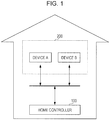
- Fig. 1 is an overall configuration diagram of a home controller system to which the home controller according to the present disclosure has been applied.
- the home controller system includes a home controller 100 (example of an information device) and devices 200 (examples of subject devices).
- the home controller 100 and one or more devices 200 are disposed within a house.
- the home controller 100 and the devices 200 perform communication with each other via a wired or wireless network, or a network including both cable and wireless.
- Examples of a cabled network which may be used include wired LAN according to the IEEE 802.3 series, and examples of a wireless network which may be used include wireless LAN according to the IEEE 802.11 series.
- the home controller 100 is not necessarily restricted to being in the house, and may be disposed outside the house. In this case, the user can control one or more devices 200 when away from home or the like.
- a mobile information terminal such as a smartphone or tablet terminal or the like is employed as the home controller 100.
- a button-operated mobile information terminal such as a cellular telephone or the like may be employed as the home controller 100.
- a laptop personal computer or desktop personal computer may be employed as the home controller 100.
- Fig. 2 is a diagram illustrating primary devices 200 to be controlled by the home controller 100.
- the home controller 100 controls devices 200 such as an air conditioning device (hereinafter referred to as "air conditioner") 201, lighting fixtures 202 and 203, a bath 204, a refrigerator 205, a washing machine 206, a toilet 207, a power curtain device 208, and so forth.
- air conditioner air conditioning device
- the devices 200 such as the air conditioner 201 and so forth illustrated in Fig. 2 are only exemplary, and devices 200 such as a television receiver (hereinafter referred to as "television"), a Blu-Ray recorder, an audio device, or the like, may be employed as devices 200. That is to say, any device may be employed as a device 200 as long as it is an electric device capable of communicating with the home controller 100.
- any device may be employed as a device 200 as long as it is an electric device capable of communicating with the home controller 100.
- electric devices used in common homes have been illustrated in Fig. 2 as devices 200, the present disclosure is not restricted to this, and office equipment used in offices and the like may be employed. Examples of office equipment include printers, personal computers, scanners, copiers, and so forth. While a house is employed as an example of a building in the present disclosure, this is not restrictive, and a concrete building, schoolhouse, or the like, may be employed.
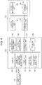
- Fig. 3 is a block diagram illustrating an example of the configuration of the home controller 100 and the devices 200.
- the home controller 100 shown in Fig. 3 includes a display 101, a touch panel control unit 102, a display control unit 103, a storage unit 104, a device registration management unit 105, a device control unit 106, and a communication control unit 107.
- the display 101 is configured including a touch panel display, for example, displaying a user interface for the user to operate the home controller 100 by, and so forth.
- the user can input various types of operations to the home controller 100 by touching the display 101.
- the touch panel control unit 102 Upon recognizing a user operation at the display 101, the touch panel control unit 102 interprets the content of the operation, and notifies the content of the operation to other components. For example, in a case where an object is displayed at the position on the display 101 where the user has tapped, the touch panel control unit 102 determines that the user has selected that object.
- Various GUI parts accepting user operations such as buttons and so forth, are employed as objects.
- the display control unit 103 generates a GUI (Graphical User Interface) for the home controller 100, to be displayed on the display 101.
- the display control unit 103 includes a room list display unit 108 and a device list display unit 109.
- the room list display unit 108 primarily governs display control of a room list screen 600 such as illustrated in Fig. 12 or Fig. 14 .
- the device list display unit 109 primarily governs display control of a device list screen 1300 such as illustrated in Fig. 13 .
- the storage unit 104 is configured using a non-volatile storage device, for example, and stores information necessary for operations of the home controller 100, such as a room list 2300 (see Fig. 23 ), a room list 2400 (see Fig. 24 ), a device list 2500 (see Fig. 25 ), and so forth, which are managed by the device registration management unit 105.
- the device registration management unit 105 follows user operations to correlate the devices 200 and rooms, creates a room list 2300 or room list 2400, and manages the room list 2300 or room list 2400. Upon a device 200 being connected to the network in the house, the device registration management unit 105 detects that device 200. The device registration management unit 105 also manages devices 200 to be controlled using a device list 2500 stored in the storage unit 104.
- the device control unit 106 issues control commands to the devices 200.
- the communication control unit 107 controls communication between the home controller 100 and the devices 200.
- the communication control unit 107 also accepts transmission requests for various types of data from other blocks, and transmits these to the devices 200, and also receives data transmitted from the devices 200 and hands this data to the relevant blocks.
- a normal display may be employed for the display 101, instead of a touch panel display.
- the user may move a pointer displayed on the display 101 using an external input device such as a mouse or the like that is not illustrated, click on the intended object, and input selection instruction of objects. That is to say, the series of operations performed by the user touching the display 101 in the present disclosure can be substituted by operations of moving the pointer using an external input device such as a mouse, clicking, and so forth.
- the device 200 has a control execution unit 211, a state management unit 212, a communication control unit 213, and a storage unit 214, as illustrated in Fig. 3 .
- the control execution unit 211 receives control commands from the home controller 100, and controls the device 200 according to the received control commands.
- the content of control of the device 200 by the control execution unit 211 depends on the type of the device 200. For example, if the device 200 is a lighting fixture, the control execution unit 211 turns the lighting fixture on/off.
- the control execution unit 211 also transmits the results of executing the control commands, and the state of the device 200, to the home controller 100.
- the state management unit 212 manages the state of the device 200.
- the content of management of the device 200 by the state management unit 212 depends on the type of the device 200. For example, in a case where the device 200 is a lighting fixture, the state management unit 212 manages whether the lighting fixture is currently in an on state or an off state.
- the storage unit 214 stores information relating to the state of the devices 200 which the state management unit 212 is managing.
- the communication control unit 213 controls communication between the devices 200 and the home controller 100.
- the communication control unit 213 also accepts transmission requests for various types of data from other blocks, and transmits these to the home controller 100, and also receives data transmitted from the home controller 100 and hands this data to the relevant blocks.
- a television 100X may be employed as an example of the information device, as illustrated in Fig. 4 .
- Fig. 4 is a block diagram illustrating an example of the configuration of the television 100X and a device 200 in a case where the television 100X has been employed as the information device.
- the points of difference in Fig. 4 as to Fig. 3 are that a remote controller instruction accepting unit 102X is provided instead of the touch panel control unit 102, and that the television 100X has a remote controller 110.
- a television capable of receiving digital terrestrial broadcasting can be employed as the television 100X.
- the remote controller 110 is a remote controller which is used with the television capable of receiving digital terrestrial broadcasting. This sort of remote controller 110 has a direction buttons for up, down, left, right, to move a cursor displayed on the display 101, and an OK button to finalize the selection made by the user, and so forth.
- this remote controller 110 can handle the same functions as the touch panel display. For example, in a case of selecting one out of multiple objects, the user of a touch panel display inputs a tapping operation on the one object to be selected. On the other hand, the user of the remote controller 110 can select one object by positioning the cursor on the one object to be selected, and pressing the OK button. Thus, the remote controller 110 has direction buttons and an OK button, so the user can operate a GUI by making a certain amount of changes to the GUI designed from the touch panel display. Accordingly, the television 100X is employed as an example of the information device, as well as the home controller 100. In this case, the television 100X serves the functions of the home controller 100.
- the remote controller instruction accepting unit 102X is configured including a communication device that receives instruction signals transmitted from the remote controller 110, and a processor or the like which decodes the instruction signals received by the communication unit, for example.
- the remote controller instruction accepting unit 102X receives instruction signals representing instructions which the user has given as to the television 100X by operating the remote controller 110, and decodes the received instruction signals. While the processing of the remote controller instruction accepting unit 102X will not be described in detail hereinafter, since description will be made primarily regarding the home controller 100, the remote controller instruction accepting unit 102X serves the same role as the touch panel control unit 102.
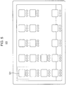
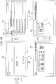
- Fig. 5 is a diagram illustrating an example of an application list screen 500.
- the application list screen 500 (an example of a menu screen) is a home screen displayed on the display of a standard smartphone or tablet terminal.
- a matrix of one or more icons to execute one or more applications is displayed on the application list screen 500.
- a home controller application icon 501 to execute a home controller application which causes the computer to function as the home controller 100 is included in the one or more icons.
- the home controller application icon 501 is situated to the left side.
- the room list display unit 108 of the display control unit 103 displays the room list screen 600 illustrated in Fig. 6 on the display 101.
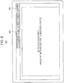
- Fig. 6 is a diagram illustrating an example of a room list screen 600 in a case where there are no devices 200 registered at the home controller 100.
- the room list screen 600 is a screen displaying a list of icons (room icons) correlated with devices 200 already registered at the home controller 100.
- Batch device operation buttons 602 and a settings button 601 are placed at the top of the room list screen 600.
- the batch device operation buttons 602 are to operate all devices set in the house of the user at once.
- four batch device operation buttons 602 of "OUT”, “TIMER”, “MODE 1", and “MODE 2" are provided as the batch device operation buttons 602.
- Control patterns of all devices 200 installed in the house are registered in each of these four batch device operation buttons 602 beforehand. For example, a control pattern is registered as the control pattern for the "OUT" batch device operation button 602 where all devices 200 are turned off at once, except for devices to remain in an on state at all times like the refrigerator. Accordingly, when the user selects the "OUT" batch device operation button 602, all devices 200 other than devices 200 to be kept on at all times are set to an off state all at once.
- the settings button 601 is a button to transition the home controller 100 to a phase for registering devices 200 at the home controller 100.
- the device list display unit 109 of the display control unit 103 displays a subject device list screen 700 illustrated in Fig. 7 on the display 101.
- Fig. 7 is a diagram illustrating an example of the subject device list screen 700.
- the subject device list screen 700 includes a device list display space 703 for displaying a list of the devices 200 installed in the house.
- the device list display space 703 displays a list of devices 200 which have responded to a device search request transmitted from the home controller 100. That is to say, devices 200 which the home controller 100 has detected are displayed as a list in the device list display space 703.
- the device list display space 703 has one device display space 706 provided for each device.
- three air conditioners and two air conditioners have responded, so five device display spaces 706 corresponding to the five devices 200 are displayed in the device list display space 703.
- each of these five devices 200 is unregistered at the home controller 100, so the device display space 706 has a mark 707 displayed indicating that these are unregistered.
- a message "YOU CAN REGISTER THIS DEVICE FROM THE "OK” BUTTON OF YOUR REMOTE CONTROLLER.” is displayed in each device display space 706 for each of these five devices 200, prompting the user to register the device 200.
- a tab 704 that says “NETWORK DEVICES” and a tab 705 that says “INFRARED DEVICES” are situated at the top of the device list display space 703.
- a list is displayed in the device list display space 703 of the devices 200 that are connected to the home controller 100 via network such as LAN or the like.
- a list is displayed in the device list display space 703 of the devices 200 that are connected to the home controller 100 via infrared communication.
- a search-again button 702 is displayed at the upper right of the subject device list screen 700, for causing the home controller 100 to search for devices 200 again.
- the device registration management unit 105 transmits a device search request to the network again, and executes a search for devices 200.
- the devices 200 detected by this search are displayed as a list in the device list display space 703, thereby updating the device list display space 703.
- a back button 701 provided to the upper left of the subject device list screen 700 is a button for returning the current display screen on the display 101 to the display screen that had been displayed one screen prior.
- the screen which had been displayed prior to the subject device list screen 700 being displayed is the room list screen 600 illustrated in Fig. 6 , so when the user selects the back button 701, the display 101 displays the room list screen 600 illustrated in Fig. 6 .
- the room list display unit 108 displays a device registration screen 800 on the display 101, as illustrated in Fig. 8 .
- the user may select the device 200 to be registered by tapping on the device display space 706 corresponding to the device 200 to be registered.
- the user may use the remote controller 110 to position the cursor on the device display space 706 corresponding to the device to be registered, and press the OK button on the remote controller 110, thus selecting the device 200 to be registered.
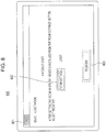
- Fig. 8 is a diagram illustrating an example of the device registration screen 800.
- the device registration screen 800 is for registering one device 200 to be registered at the home controller 100.
- the air conditioner displayed in the first-row device display space 706 in the subject device list screen 700 illustrated in Fig. 7 has been selected by the user, thereby bringing up the device registration screen 800.
- the device registration screen 800 in Fig. 8 says "AIR CONDITIONER". Accordingly, the user can confirm that the device 200 to be registered is the air conditioner, thereby preventing another device 200 from being the object of registration.
- a message "AFTER SETTING THE ROOM WHERE THE DEVICE IS INSTALLED FROM THE 'ROOM SETTINGS' BUTTON, SELECT 'REGISTER'.” is displayed below the display "AIR CONDITIONER" in the device registration screen 800, informing the user that the device 200 and the room can be correlated by operating a room selection screen display button 802 and a device registration button 803.
- the display screen of the display 101 returns to the subject device list screen 700 illustrated in Fig. 7 .
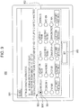
- Fig. 9 is a diagram illustrating an example of the room selection screen 900.
- the room selection screen 900 is a screen for the user to correlate a device 200 to be registered with the room in which that device 200 is installed.
- a heading "SETTINGS FOR INSTALLATION ROOMS" is at the top of the room selection screen 900, information the user that the room selection screen 900 is a screen for selecting rooms. Below the "SETTINGS FOR INSTALLATION ROOMS" heading, a message "SET THE ROOM WHERE THE DEVICE IS INSTALLED. SELECT FROM THE ROOM NAMES, AND SELECT 'SET'.” is displayed. Thus, the user can comprehend that selecting one room from the rooms displayed in a room candidate list 902 and selecting a room set button 905 correlates the device 200 to be registered and the room.
- the room candidate list 902 displays a list of candidates of rooms to be correlated with the device 200 to be registered. What is displayed in the room candidate list 902 here is not a list or rooms which actually exist in the houses of each of the users, but rather a list of rooms which generally exist in homes, such as "living room”, “reception room”, and "bedroom”. That is to say, a list of rooms registered beforehand by a designer of the home control system according to the present disclosure is displayed in the room candidate list 902. Accordingly, the same rooms are displayed in the list in the room candidate list 902 for all users using the home control system according to the present disclosure.
- Rooms making up a house can often be identified by common names, such as the living room, reception room, and so forth. Also, if simply correlating a device 200 and a room is sufficient, room layout information indicating which part of which floor of the house that room is situated is unnecessary. Accordingly, in the present disclosure, a list of commonly-existing rooms is displayed in the room candidate list 902, for the user to select one from. Accordingly, the present disclosure realizes correlating the devices 200 with rooms without having users to input room layout information of the houses of individual users.
- 20 radio buttons 904 are disposed, corresponding to each of the rooms displayed in the list.
- the 15 rooms displayed in the first row through the third row are rooms having general names, such as living room, reception room, and so forth.
- the five rooms displayed in the fourth row, out of the rooms displayed in the list in the room candidate list 902, are rooms where the user can input any preferred room name.
- the room candidate list 902 according to the present disclosure provides rooms where users can input preferred names, to accommodate such user demands.
- the room having the input name is registered in the home control system.
- Input of the preferred name may be performed by the user tapping on the space that says “CUSTOMER SETTING 1", to bring up a software keyboard (omitted from illustration) on the display 101, and using this software keyboard to perform input.
- the room list display unit 108 displays a selection mark 9041 in that radio button 904.
- the room list display unit 108 displays the device registration screen 800 illustrated in Fig. 10 on the display 101.
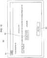
- Fig. 10 is a diagram illustrating an example of a device registration screen 800 displayed after a user has selected a room from the room selection screen 900 illustrated in Fig. 9 .
- the device registration screen 800 illustrated in Fig. 10 which represents the device 200 to be registered, is displayed at the top of the device registration screen 800 illustrated in Fig. 10 .
- the user can confirm that the "LIVING ROOM” and the "AIR CONDITIONER” are about to be correlated.
- the device list display unit 109 displays the subject device list screen 700 illustrated in Fig. 11 on the display 101.
- the device registration management unit 105 correlates the "LIVING ROOM” and the "AIR CONDITIONER” and registers in a device list 2500.
- correlation of the "LIVING ROOM" and the "AIR CONDITIONER" in the home controller 100 is finalized.
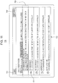
- Fig. 11 is a diagram illustrating an example of the subject device list screen 700 displayed in a case where the device registration button 803 has been selected from the device registration screen 800 illustrated in Fig. 10 .
- the subject device list screen 700 illustrated in Fig. 11 reflects the registration of the air conditioner that has been performed in the device registration screen 800 in Fig. 10 . Accordingly, the mark 707 representing the unregistered state in Fig. 7 has been deleted from the device display space 760 displayed in the first row in Fig. 11 . Further, there are two other air conditioners besides the air conditioner displayed in the first row device display space 760 in the example in Fig. 11 . Accordingly, the name of the air conditioner in the first row device display space 760 has been set to "AIR CONDITIONER 1", to distinguish the registered air conditioner in the first row device display space 760 from the other two unregistered air conditioners.
- the first row device display space 760 has a message that says "YOU CAN CHANGE THE ROOM SETTINGS OR DEREGISTER THE DEVICE FROM THE 'OK' BUTTON OF THE REMOTE CONTROLLER.” displayed.
- the user can recognize that the registration content of the "AIR CONDITIONER 1" can be changed.
- the subject device list screen 700 illustrated in Fig. 11 is the same as the subject device list screen 700 illustrated in Fig. 7 .
- the room list display unit 108 displays the room list screen 600 illustrated in Fig. 12 on the display 101.
- Fig. 12 is a diagram illustrating an example of the room list screen 600 in a case where there is only one room correlated with a device 200.
- the room list display unit 108 displays the room list screen 600 where only one room icon 603, representing the living room, is shown, on the display 101.
- the room icon 603 is a rectangular image which includes the name of the relevant room, and a simplified image representing the state of the relevant room.
- the room icon 603 shown in Fig. 12 is a room icon 603 for a living room, and accordingly includes an image showing a sofa, an ornamental plant, and furniture, which represent a living room, in a simplified manner.
- the device list display unit 109 displays the device list screen 1300 illustrated in Fig. 13 on the display 101.
- Fig. 13 is a diagram illustrating an example of the device list screen 1300.
- the device list screen 1300 is a list display of a device control screen 1306 (example of first operating screen, second operating screen) of the device 200 correlated with the room icon 603 selected from the room list screen 600.
- a device control screen 1306 example of first operating screen, second operating screen
- a temperature display space 1304 and a humidity display space 1305 are laid out at the top of the device control screen 1306 for the air conditioner 1 in the device list screen 1300.
- the temperature display space 1304 is a space for displaying the room temperature of the relevant room (living room in this case).
- the humidity display space 1305 is a space for displaying the humidity of the relevant room (living room in this case).
- the temperature and humidity of the relevant room may be acquired from the air conditioner installed in this room, by the home controller 100 for example.
- the device control screen 1306 shown in Fig. 13 is the device control screen 1306 of the air conditioner 1, so an image R1 representing the air conditioner in a simplified manner, and a name R2 (air conditioner 1 in this case) are displayed. Accordingly, the user can tell in a glance that this device control screen 1306 is that of the air conditioner 1.
- the device control screen 1306 also includes a state display space R3, a temperature display space R4, an airflow display space R5, a wind direction display space R6, and a mode display space R7.
- the state display space R3 displays information indicating whether or not the air conditioner 1 is running.
- the air conditioner 1 is running in this case, so "RUNNING" is displayed in the state display space R3.
- the state display space R3 also includes an auto button B1 to start the air conditioner 1 operating, and a stop button B2 to stop the operation of the air conditioner 1.
- the auto button B1 is selected in this case, so the auto button B1 is displayed in an active state.
- the temperature display space R4 displays the currently set temperature of the air conditioner 1.
- the temperature display space R4 has an up button B3 to raise the set temperature of the air conditioner 1 and a down button B4 to lower the set temperature of the air conditioner 1.
- the currently set temperature of the air conditioner 1 in this case is 28 degrees, so "28°C" is displayed in the temperature display space R4.
- the airflow display space R5 displays the current airflow of the air conditioner 1.
- the airflow display space R5 has an up button B5 to raise the airflow of the air conditioner 1 and a down button B6 to lower the airflow of the air conditioner 1.
- the current airflow of the air conditioner 1 is 3, so "3" is displayed in the state display space R5.
- the wind direction display space R6 displays the current wind direction of the air conditioner 1.
- the wind direction display space R6 has a wind direction button B7 to adjust the wind direction of the air conditioner 1, and multiple indicators B8 representing the current wind direction.
- the wind direction of the air conditioner 1 can be adjusted in five stages in the vertical direction, so five indicators B8 are laid out in a radial manner corresponding to the five stages of wind direction.
- the indicator B8 corresponding to the current wind direction of the air conditioner 1 is displayed in an active state, and the remaining four indicators B8 are displayed in an inactive state.
- the wind direction button B7 is pressed, the wind direction moves up or down one stage, and the indicator B8 displayed in an active state also changes accordingly.
- the mode display space R7 displays the mode of the air conditioner 1 that is currently set.
- the modes of the air conditioner 1 are cooling mode, heating mode, and dehumidifying mode, so the mode display space R7 has a cooling button B9, a heating button B10, and a dehumidify button B11, for selecting one of these three modes.
- the one of the cooling button B9, heating button B10, and dehumidify button B11 corresponding to the currently set mode is displayed in an active state, and the two remaining buttons are displayed in an inactive state.
- the cooling mode is selected is selected in the example in Fig. 13 , so the cooling button B9 is displayed in the active state, and the heating button B10 and dehumidify button B11 are displayed in an inactive state.
- the room list display unit 108 Upon the touch panel control unit 102 detecting an operation of selecting a back button 1303 in the device list screen 1300 illustrated in Fig. 13 , the room list display unit 108 returns the display screen of the display 101 to the room list screen 600 illustrated in Fig. 12 .
- a settings button 1301 and batch device operation buttons 1302 are placed at the upper side of the device list screen 1300 illustrated in Fig. 13 .
- the device list display unit 109 displays the subject device list screen 700 on the display 101, in the same way as in a case where the settings button 601 is selected in Fig. 6 .
- the device control unit 106 performs batch control of the devices 200 within the house, in the same way as in a case where the batch device operation buttons 602 are selected in Fig. 6 . Note that in a case where the batch device operation buttons 602 are selected, the device control unit 106 may perform batch control only of the devices 200 correlated with the relevant room (living room in this case).
- Fig. 14 is a diagram illustrating an example of the room list screen 600 in a case where there are multiple rooms which have been correlated with devices 200.
- there are multiple rooms which have been correlated with devices 200 so multiple room icons 603 are laid out on the room list screen 600.
- the room list screen 600 displays the room icons 603 in a matrix in order of registration, such as the room icon 603 of the room that was registered first in a tile at the first row and first column, the room icon 603 of the room that was registered second in a tile at the first row and second column, and so on.
- the display order of the room icons 603 is not restricted to the order of registration.
- the room list screen 600 has a size that is capable of displaying three columns worth of room icons 603 in each row, the room icon 603 of the room that was registered fourth is displayed in a tile at the second row and first column, and the room icon 603 of the room that was registered seventh in a tile at the third row and first column.
- the room list screen 600 has a size capable of displaying the entire regions of a total of six room icons 603, made up of two rows x three columns, and a region of about two thirds from the top of a third row of three room icons 603, at the same time, for example.
- the number of rooms to which devices 200 have been correlated is nine or more, so all room icons 603 cannot be displayed in the room list screen 600 at once. Accordingly, a switch button 1401 to switch the display of the room list screen 600 is provided at the lower middle portion of the room list screen 600 in Fig. 14 .
- the room list display unit 108 scrolls the room icons 603 one tile worth upwards. Accordingly, the three room icons 603 "Japanese room”, “kitchen”, and “study”, displayed in the second row are displayed in the first row, and the three room icons 603 "reception room”, "bedroom 2", and “children's room 2", displayed in the third row are displayed in the second row. In this case, if there are room icons 603 in the tiles one below the "reception room”, "bedroom 2", and “children's room 2", these room icons 603 will be displayed in the third row. Further, upon an operation of selecting the switch button 1401 being input, the room list display unit 108 scrolls the room icons 603 another one tile worth upwards. Thus, each time the switch button 1401 is selected, the room icons 603 are scrolled one tile worth upwards.
- a switch button (omitted from illustration) to scroll the room icons 603 downwards by one row worth is provided at the upper middle portion of the room list screen 600.
- the "living room”, “bedroom 1", and “children's room 1”, which had been removed from display by operating the switch button 1401 are displayed on the display 101.
- Fig. 14 if one of the devices 200 out of the devices 200 correlated with a corresponding room is in an on state, the room icon 603 thereof is displayed in an active state. For example, a device 200 correlated with the living room is in an on state, so the room icon 603 of the "living room” is displayed in an active state. On the other hand, if all of the devices 200 correlated with a corresponding room are in an off state, the room icon 603 thereof is displayed in an inactive state. For example, all devices 200 correlated with the study are in an off state, so the room icon 603 of the "study" is displayed in an inactive state.
- a display form of displaying room icons 603 in an inactive state may be a form of graying out the room icon 603, for example. Displaying the images and text within the room icon 603 in a monotone gray color here grays out the display of the room icon 603.
- a display form of displaying room icons 603 in an active state may be a normal display form of the room icon 603. Displaying the images and text within the room icon 603 in the original color without graying out is the normal display form here.
- the room list screen 600 displays in a list the room icons 603 representing rooms in the house with which devices 200 have been correlated, so primary rooms existing in the house can be presented to the user. Accordingly, while the position of the rooms in the layout of the house cannot be displayed in the room list screen 600, the functionality borne is one such as if it were that of a room layout diagram.
- the room icon 603 of that room is automatically displayed in the room list screen 600. Accordingly, the user does not have to perform separate work to input the room layout information to create the room list screen 600.
- this home control system enables the room list screen 600, which has a function as if it were a room layout diagram, to be displayed on the display 101, without imposing the work of inputting room layout information on the user.
- the device list display unit 109 displays the device list screen 1300 illustrated in Fig. 15 on the display 101.
- Fig. 15 is a diagram illustrating an example of the device list screen 1300 where multiple devices 200 are correlated.
- An air conditioner 1, lighting fixture 1, and air conditioner 2 are correlated with the living room in the device list screen 1300 in Fig. 15 , so three device control screens 1306, corresponding to the three devices 200, are displayed in the device list screen 1300 in Fig. 15 . Otherwise, the device list screen 1300 in Fig. 15 is the same as the device list screen in Fig. 13 .
- the device control screens 1306 are displayed in order of registration of order in the device list screen 1300, such as the device control screen 1306 of the device 200 registered first in the living room at the first row, the device control screen 1306 of the device 200 registered second at the second row, and so forth.
- symbols to identify order of registration are employed as device IDs ( Fig. 25 ), such as the device 200 registered first being "A”, the device 200 registered second being "B”, and so on.
- the device list display unit 109 only has to display the device control screens 1306 of the devices 200 correlated with the relevant room in order of the device IDs.
- the air conditioner 1 has been correlated first in the living room, the lighting fixture 1 has been correlated second, and the air conditioner 2 has been correlated third, so the device control screens 1306 for air conditioner 1, lighting fixture 1, and air conditioner 2 are displayed in the first, second, and third rows.
- the device list screen 1300 has a size capable of displaying the entire regions of two device control screens 1306, and the upper half of another device control screen 1306, at the same time, for example. Accordingly, if four or more devices 200 are correlated with the living room, the fourth and subsequent device control screens 1306 cannot be displayed. Accordingly, a switch button 1307 to display the unshown device control screens 1306 on the display 101 is provided at the lower middle portion of the device list screen 1300.
- the device list display unit 109 scrolls the device list screen 1300 one row upwards. Accordingly, the device control screen 1306 of the lighting fixture 1 displayed in the second row is displayed in the first row, and the device control screen 1306 of the air conditioner 2 displayed in the third row is displayed in the second row. In this case, if there is another device control screen 1306 situated below the air conditioner 2, the device control screen 1306 of this device is displayed in the third row. Inputting further operation to select the switch button 1307 scrolls the device control screens 1306 one row further upwards. Thus, each time the switch button 1307 is selected, the device list display unit 109 scrolls the device control screen 1306 upwards in increments of rows.
- a switch button (omitted from illustration) to scroll the device control screen 1306 downwards by one row worth is provided at the upper middle portion of the device list screen 1300.
- the device control screen 1306 for the air conditioner 1 which had been removed from display by operating the switch button 1307, is displayed on the display 101.
- a settings button 1301 and batch device operation buttons 1302 are placed at the upper side of the device list screen 1300 illustrated in Fig. 15 , the same way as in the device list screen 1300 illustrated in Fig. 13 .
- Fig. 16 is a diagram illustrating an example of a screen flow for initial settings.
- the term initial settings here means a device 200 being registered for the first time, in a state where there are no devices 200 at all that have been registered.
- the room list display unit 108 switches the display screen of the display 101 from the application list screen 500 to the room list screen 600 (C161).
- the room list screen 600 illustrated in Fig. 6 is displayed on the display 101.
- a touch pen may be employed as the instructing object X, or a finger of the user may be used.
- Fig. 17 is a diagram illustrating an example of the screen flow continued from Fig. 16 .
- the room list screen 600 at the upper left in Fig. 17 is the room list screen 600 in Fig. 6 .
- the device list display unit 109 switches the display screen on the display 101 from the room list screen 600 to the subject device list screen 700 (C171).
- the subject device list screen 700 displayed here is the subject device list screen 700 illustrated in Fig. 7 .
- the room list display unit 108 switches the display screen on the display 101 from the subject device list screen 700 to the device registration screen 800 (C172).
- the device registration screen 800 displayed here is the device registration screen 800 illustrated in Fig. 8 .
- the room list display unit 108 switches the display screen of the display 101 from the device registration screen 800 to the room selection screen 900 (C173).
- the room list display unit 108 switches the display screen on the display 101 from the room selection screen 900 to the device registration screen 800 (C174).
- the name or the room which has been correlated with this device 200 is displayed to the right of the room selection screen display button 802 in the device registration screen 800.
- the room selection screen display button 802 is selected, the room selection screen 900 is displayed, and the user can correlate this device 200 with another room using the room selection screen 900.
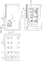
- Fig. 18 a diagram illustrating an example of the screen flow continued from Fig. 17 .
- the device registration screen 800 at the upper left in Fig. 18 is the device registration screen 800 illustrated in Fig. 10 , for correlating the air conditioner and the living room, since the living room has been selected for the air conditioner.
- the device list display unit 109 switches the display screen on the display 101 from the device registration screen 800 to the subject device list screen 700 (C181).
- the subject device list screen 700 displayed here is the subject device list screen 700 in Fig. 11 , showing that the air conditioner 1 is a registered device 200.
- the room list display unit 108 switches the display screen on the display 101 from the subject device list screen 700 to the room list screen 600 (C182).
- the room list screen 600 displayed here is the room list screen 600 illustrated in Fig. 12 , where only the room icon 603 of the living room is displayed.
- the device list display unit 109 switches the display screen on the display 101 from the room list screen 600 to the device list screen 1300 (C183). Only the air conditioner 1 is correlated with the living room here, so the device list screen 1300 illustrated in Fig. 13 , including only the device control screen 1306 of the air conditioner 1 is displayed.
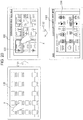
- Fig. 19 is a diagram illustrating an example of a screen flow where a home controller application icon is activated in a case where only one room is registered.
- the room list display unit 108 switches the display screen of the display 101 from the application list screen 500 to the room list screen 600 (C191).
- the room list screen 600 illustrated in Fig. 12 including only the room icon 603 for the living room, is displayed on the display 101 here.
- the device list display unit 109 switches the display screen on the display 101 from the room list screen 600 to the device list screen 1300 (C192).
- the air conditioner 1, lighting fixture 1, and air conditioner 2 are correlated with the living room here, so the device list screen 1300 shown in Fig. 15 , which includes the three device control screens 1306 for the air conditioner 1, lighting fixture 1, and air conditioner 2, is displayed on the display 101.
- Fig. 20 is a diagram illustrating an example of a screen flow where a home controller application is activated in a case where multiple rooms are registered.
- the difference of Fig. 20 as to Fig. 19 is the point that, upon the touch panel control unit 102 detecting an operation of an instructing object X tapping a home controller application icon 501 at the application list screen 500, the room list screen 600 illustrated in Fig. 14 , which includes multiple room icons 603, is displayed on the display 101 (C191). That is to say, multiple rooms that have been correlated with devices 200 exist in the example in Fig. 20 , so the room list screen 600 displaying a list of the room icons 603 of these rooms is displayed on the display 101.
- the instructing object X has tapped the room icon 603 for the living room from the room list screen 600, so the display screen of the display 101 has switched from the room list screen 600 to the device list screen 1300 (C192).
- the device list screen 1300 displayed here is the device list screen 1300 in Fig. 15 .
- the room list screen 600 is displayed on the display 101 regardless of the number of registered rooms. Note however, that this is only an example, and that an arrangement may be made where the home controller 100 bypasses display of the room list screen 600 in a case where the number of registered rooms is one, and displays the device list screen 1300.
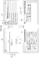
- Fig. 21 is a diagram illustrating a first modification of the screen flow.
- the room list display unit 108 switches the display screen 101 from the application list screen 500 to the room list screen 600 if the number of registered rooms is multiple (C2101).
- the device list display unit 109 switches the display screen of the display 101 from the room list screen 600 to the device list screen 1300 (C2102).
- the room list display unit 108 switches the display screen of the display 101 from the application list screen 500 to the device list screen 1300 (C2103).
- the display screen of the display 101 is switched from the application list screen 500 to the device list screen 1300 without going through the room list screen 600. This reduces the number of operating steps by the user, and the number of processing steps by the home controller 100.
- Fig. 22 is a diagram illustrating a second modification of the screen flow.
- the screen flow in Fig. 22 is a modification of the screen flow illustrated in Fig. 18 , and is a configuration of the screen flow from Fig. 17 .
- the device list display unit 109 switches the display screen on the display 101 from the device registration screen 800 to the subject device list screen 700 (C181). This point is the same as in Fig. 18 . If the number of registered rooms is multiple, upon the back button 701 being tapped by the instructing object X in the subject device list screen 700, the room list display unit 108 switches the display screen of the display 101 from the subject device list screen 700 to the room list screen 600 (C2202).
- the device list display unit 109 switches the display screen of the display 101 from the subject device list screen 700 to the device list screen 1300, without going through the room list screen 600 (C2201).
- the display screen of the display 101 is switched from the subject device list screen 700 to the device list screen 1300 without going through the room list screen 600. This reduces the number of operating steps by the user, and the number of processing steps by the home controller 100.
- the present disclosure may combine both the first modification and the second modification, or may use just one.
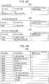
- Fig. 23 is a diagram illustrating a room list 2300 according to a first example which the device registration management unit 105 manages.
- the room list 2300 is data for managing the number of devices 200 correlated with each room.
- a feature of the room list 2300 according to the first example is that rooms regarding which the number of registered devices 200 is one or more are registered, and rooms regarding which the number of registered devices 200 is 0 are not registered.
- the top tier in Fig. 23 represents the room list 2300 in an initial state
- the middle tier represents the room list 2300 in a case where the number of registered rooms is one
- the bottom tier represents the room list 2300 in a case where the number of registered rooms is two.
- the room list 2300 has a data structure where one record is assigned to each room, having the items of "ROOM ID”, "ROOM NAME”, and “NUMBER OF DEVICES REGISTERED".
- ROOM ID is an identifier for identifying each room uniquely.
- ROOM NAME is the name of each room.
- NUMBER OF DEVICES REGISTERED is the number of devices 200 which have been correlated with the room at the device registration screen 800.
- the number of registered rooms in the initial state is 0, so the number of rooms registered in the room list 2300 is 0.
- the room list 2300 has one record corresponding to this one room, as can be seen from the middle tier.
- the "LIVING ROOM” is registered as this one room, so "LIVING ROOM” is registered as "ROOM NAME”.
- Room names displayed in the list in the room candidate list 902 of the room selection screen 900 are registered in the "ROOM NAME". In a case where a room having a room name which the user has optionally input at the room selection screen 900 is selected, the name of that room is registered to "ROOM NAME".
- the living room is the room registered first, so "R001” is registered as “ROOM ID”.
- a symbol string is employed for the "ROOM ID”, where a numerical value is increment by 1 in order of registration.
- the room list display unit 108 decides the order of array of the room icons 603 on the room list screen 600 according to the order of "ROOM ID". For example, the room icon 603 of the room of which the "ROOM ID” is "R001" is arrayed in the tile at the first row and first column, and the room icon 603 of the room of which the "ROOM ID” is “R002" is arrayed in the tile at the first row and second column.
- the room list 2300 has two or more records corresponding to this one room, as can be seen from the lower tier.
- the "LIVING ROOM” and “RECEPTION ROOM” are registered here, so two records corresponding to "LIVING ROOM” and “RECEPTION ROOM” are registered as “ROOM NAME”.
- the reception room has been registered second, so “R002” is registered as “ROOM ID”.
- the room list 2300 has registered therein the rooms with one or more devices registered thereto and the name of the rooms, so the room list display unit 108 can identify how many room icons 603 to display representing which rooms in the room list screen 600 by referencing the room list 2300.
- the room list display unit 108 and device list display unit 109 can determine whether the number of registered rooms is one or multiple by referencing the room list 2300.
- rooms where the number of correlated devices 200 is 0 are not registered in the room list 2300, so the amount of data is reduced.
- Fig. 24 is a diagram illustrating a room list 2400 according to a second example, which the device registration management unit 105 manages.
- the room list 2400 differs from the room list 2300 in that all rooms set beforehand to be managed by the home controller system are registered, regardless of the number of registered devices. For example, the "ENTRANCE" is registered in the room list 2400 even through the "NUMBER OF DEVICES REGISTERED" is 0. Otherwise, the room list 2400 is the same as the room list 2300.
- Rooms which are set beforehand to be managed correspond to the room candidate list 902 in the room selection screen 900. Accordingly, the records corresponding to each room displayed as a list in the room candidate list 902 are registered in the room list 2400 beforehand.
- the records corresponding to the "CUSTOMER SETTING 1" through “CUSTOMER SETTING 5" shown in the room candidate list 902 are also registered in the room list 2400 beforehand.
- the room name "CUSTOMER SETTING 1" in the room list 2400 is rewritten to "so-and-so's bedroom".
- rooms where the "NUMBER OF DEVICES REGISTERED" is one or more correspond to registered rooms, and rooms where the "NUMBER OF DEVICES REGISTERED" is 0 correspond to unregistered rooms.
- the room list display unit 108 may extract one or more rooms from the room list 2400 where the "NUMBER OF DEVICES REGISTERED" is one or more, and arrange room icons 603 for the extracted rooms on the room list screen 600 in order of the room ID.
- the room icons 603 are arrayed on the order of living room, reception room, and so forth, for example, but the number of devices registered for the entrance is "0", so the room icon 603 for the bedroom 1 is disposed next after the Japanese room. Accordingly, when the room list 2400 is employed, the room icons 603 is arrayed not in order of registration, rather, the room icons 603 are arrayed in order of room IDs provided beforehand to each room.
- the room icons 603 are arrayed on the room list screen 600 in the order of room IDs, the array of the room icons 603 may be changed according to user preferences.
- the room icon 603 may be thereafter situated at the position to which it was moved.
- the home controller 100 may have tile information in the room lists 2300 and 2400, indicating the position where the room icon 603 is to be placed.
- Tile information is information such as the tile at row 1 and column 1, the tile at row 1 and column 2, and so forth. Assuming a situation where the room icon 603 for the living room that was situated at the tile at row 1 and column 1 in the room list screen 600 in Fig.
- the room list display unit 108 displays the room icon 603 for the living room at the tile at row 1 and column, so the icons for the bedroom at row 1 and column 2, and the children's bedroom at row 1 and column 3, can be shifted to the tile at row 1 and column 1, and the tile at row 1 and column 2, and thus displayed.
- Fig. 25 is a diagram illustrating an example of data configuration of a device list 2500 which the device registration management unit 105 manages. Based on the information in this device list 2500, the device list display unit 109 displays marks 707 in the subject device list screen 700 indicating that devices are not registered, displays device control screens 1306 of devices 200 correlated with the relevant room in the device list screen 1300, and so forth.
- the device list 2500 includes device ID 2501, device type 2502, model number 2503, room-where-installed 2504, capability information 2505, control command transmission destination 2506, IP address 2507, energy consumption 2508, and status 2509.
- the device ID 2501 is an identifier for the device 200.
- the device type 2502 indicates the type of the device 200.
- the model number 2503 indicates the model number of the device 200.
- the room-where-installed 2504 indicates the room with which the device 200 has been correlated. Correlating the device 200 and the room is performed by the user using the device registration screen 800 and room selection screen 900.
- the capability information 2505 indicates what about the device 200 can be controlled, and states that can be acquired from the device 200. For example, the temperature, wind direction, and airflow of the air conditioner with device ID A can be controlled.
- the home controller 100 may acquire capability information from the device 200 via the network, and register it in the capability information 2505.
- the control command transmission destination 2506 indicates the destination of the control command for controlling the device 200.
- "DEVICE" is registered as the control command transmission destination 2506 for all devices 200, so the control commands are directly transmitted from the home controller 100 to the device 200.
- control commands are transmitted via a server (omitted from illustration) on the Internet, for the manufacturer of the device 200 to provide services to the user.
- a server (omitted from illustration) on the Internet
- "SERVER" is registered as the control command transmission destination, and the home controller 100 transmits control commands to the device 200 via the server.
- a control command is a command for operating the device 200, confirming the state of the device 200, and so forth.
- the IP address 2507 is an IP address assigned to the device 200.
- the home controller 100 may register the IP address which it has assigned itself in the IP address 2507.
- the IP address may be acquired from the external device or the device 200, and registered in the IP address 2507.
- the energy consumption 2508 represents the amount of electric power consumed by the devices 200.
- the energy consumption per hour (kwh) of the device 200 is used as the energy consumption. If the energy consumption is managed by a smart distribution board (omitted from illustration) installed in the house, the home controller 100 may acquire the energy consumption from the smart distribution board, and if managed by each device 200, the home controller 100 may acquire the energy consumption directly from the device 200.
- the status 2509 represents the current state of the device 200.
- the current set temperature of the air conditioner of which the device ID is A is 27 degrees, so "27°C" is registered as the status.
- the home controller 100 may periodically query the device 200 for the state, and update the status 2509 with the state which the response from the device 200 indicates.
- Fig. 26 is a sequence diagram illustrating an example of processing at the time of the home controller 100 detecting devices 200. Explanation will be made regarding an arrangement where there are two devices 200, device A and device B, on a network to which the home controller 100 is connected. Note however, that this is an example, and that any number of devices 200 connected to the network may be employed, from 0 or more.
- the device list display unit 109 of the home controller 100 displays the subject device list screen 700 on the display 101 (S2601).
- the device registration management unit 105 of the home controller 100 transmits a device search request to device A and device B (S2602).
- the device registration management unit 105 may transmit a device search request immediately after the display screen of the display 101 has been changed to the subject device list screen 700, and thereafter transmit a device search request each time the search-again button 702 is selected at the subject device list screen 700.
- the device registration management unit 105 may transmit the device search request to the network by broadcasting.
- the device A transmits a device search response to the home controller 100 (S2603).
- the device registration management unit 105 transmits an acquisition request for device information of the device A (S2604), and acquires device information of the device A.
- This device information includes a device ID.
- the device registration management unit 105 determines whether the device A is a registered device 200 or an unregistered device 200, using the acquired device information (S2605). If the device ID included in the acquired device information is registered in the device list 2500, determination may be made that the device A has been registered, and if not registered, that the device A is not registered.
- the device list display unit 109 updates the subject device list screen 700 in accordance with the determination results of S2605 (S2606).
- the mark 707 indicating not registered is displayed in the device display space 706 for the device A
- the mark 707 indicating not registered is not displayed in the device display space 706 for the device A.
- the device B transmits the device search response to the home controller 100 (S2607).
- the device registration management unit 105 transmits an acquisition request for device information of the device B (S2608), and acquires device information of the device B.
- the device registration management unit 105 determines whether the device B is a registered device 200, in the same way as with the device A (S2609).
- the device list display unit 109 updates the subject device list screen 700 in accordance with the determination results in S2609 (S2610).
- Fig. 27 is a flowchart illustrating an example of the overall processing of the home controller 100.
- the home controller 100 activates the home controller application icon (S2701).
- the device registration management unit 105 acquires the room list 2300 or the room list 2400 (S2702). Now, the device registration management unit 105 acquires the room list 2300 or the room list 2400 by reading out the room list 2300 or room list 2400 from the storage unit 104.
- the room list 2300 or room list 2400 will collectively be referred to as room list 2300.
- the device registration management unit 105 references the room list 2300 and determines whether or not the number of rooms with one or more registered devices is two or more (S2703). In a case where the number of rooms with one or more registered devices is two or more (YES in S2703), the device registration management unit 105 instructs the room list display unit 108 to display the room list screen 600 (S2704).
- the room list 2300 at the bottom tier in Fig. 23 the number of registered devices for the living room is "4" and the number of registered devices for the reception room is "1", so the number of rooms with one or more registered devices is two or more, and accordingly a determination of YES is made in S2703.
- room list screen display processing is executed (S2705), and the processing is returned to S2702. This processing will be described in detail later.
- the device registration management unit 105 references the room list 2300, and determines whether or not the number of rooms with one or more registered devices is one or more (S2706). In a case where the number of rooms with one or more registered devices is one or more (YES in S2706), the device registration management unit 105 instructs the device list display unit 109 to display the device list screen 1300 for the one room where devices are registered (S2707). In the example of the room list 2300 at the middle tier in Fig. 23 , so the number of rooms with one or more registered devices is one, the "LIVING ROOM", and accordingly a determination of YES is made in S2706.
- the device registration management unit 105 determines that not one device 200 is registered (YES in S2709), and the room list display unit 108 displays an empty room list screen 600 ( Fig. 6 ) with no room icons 603 displayed (S2710).
- the room list display unit 108 accepts operations of selecting the settings button 601 at the empty room list screen 600 (S2711).
- device registration processing is executed (S2712), and the flow returns to S2702. Note that the processing is also returned to S2702 in the case of NO at S2709 as well.
- Fig. 28 is a flowchart illustrating an example of room list screen display processing.
- the room list display unit 108 acquires the room list 2300 (S2801).
- the room list display unit 108 confirms the number of registered device for each room registered in the room list 2300, one room at a time (S2802).
- a room which is the object of confirmation regarding registered devices will be referred to as room for confirmation.
- the room list display unit 108 determines whether the number of registered devices in a room for confirmation is one or more (S2804). In a case where the number of registered devices at the room for confirmation is one or more (YES in S2804), the room list display unit 108 sets the room for confirmation to be displayed in the room list screen 600 (S2805). On the other hand, in a case where the number of registered devices at the room for confirmation is 0 (NO in S2804), the room list display unit 108 sets the room for confirmation as a non-display room in the room list screen 600 (S2810), and the flow returns to S2803.
- the room list display unit 108 references the device list 2500, and acquires a device list of devices set in the room for confirmation.
- the room for configuration is the living room
- the living room has the air conditioner, shutter, and lighting fixture correlated, so the device information of these devices 200 is included in the device list.
- One device information is information registered in one record in the device list 2500, i.e., information whereby the installation room of the device and the device ID can be identified.
- the room list display unit 108 determines whether or not all devices 200 are off in the acquired device list (S2807). Now, the room list display unit 108 may determine whether or not all devices 200 are in an off state, by referencing the status 2509 of the device list 2500.
- the room list display unit 108 displays the room icon 603 of the room for confirmation in a grayed out form in the room list screen 600 (S2808).
- the room list display unit 108 displays the room icon 603 of the room for confirmation in a color state (active state) in the room list screen 600 (S2809).
- the room list screen 600 in Fig. 14 all devices 200 are off in the Japanese room and the study, so the room icons 603 for the Japanese room and the study are displayed grayed out.
- at least one device 200 is on in all other rooms besides the Japanese room and the study, and accordingly these are displayed in an active state.
- Fig. 29 is a flowchart illustrating an example of room list screen display processing continuing from Fig. 28 .
- the home controller 100 goes into a standby state, awaiting input from the user to the room list screen 600.
- the touch panel control unit 102 instructs the device list display unit 109 to display the device list screen 1300 of the room corresponding to the selected room icon 603 (S2905).
- device list screen display processing is executed (S2708), and room list screen display processing ends.
- the device list screen display processing will be described in detail later.
- the device control unit 106 executes device batch control according to the batch device operation button 602 that has been selected (S2908), and the flow returns to S2901.
- NO is yielded in S2907, i.e., in a case where none of the settings button 601, room icon 603, and batch device operation button 602 are selected from the room list screen 600, the flow returns to S2901, and the standby state for user input is maintained.
- Fig. 30 is a flowchart illustrating an example of device list screen display processing in S2708 in Fig. 27 and Fig. 29 .
- the device list screen display processing is executed in a case where the home controller application icon 501 has been selected from the application list screen 500 and there is one room where the number of registered devices is one or more in Fig. 27 (YES in S2706).
- the device list screen display processing is executed in a case where a room icon 603 has been selected from the room list screen 600 in Fig. 29 (YES in S2904).
- the device list display unit 109 references the device list 2500, and displays the device list screen 1300 for the specified room (S3001).
- the specified room means one room registered in the room list 2300
- the specified room means the room corresponding to the room icon 603 selected by the user from the room list screen 600.
- the device list display unit 109 displays the device list screen 1300 where the device control screens 1306 for the air conditioner, shutter, and lighting fixture are arrayed.
- the home controller 100 goes to a standby state for user input to the device list screen 1300 (S3002).
- the flow returns top S3001 after device registration processing (S2712) is executed.
- the device registration processing will be described later in detail.
- the device control unit 106 executes device control processing (S3006).
- S3006 A case where any button included in a device control screen 1306 is selected falls under selection of the device control screen 1306.
- device control processing means transmitting a control command corresponding to the button selected at the device control screen 1306 to the relevant device 200, to cause this device 200 to execute control correlated with the selected button.
- the device control unit 106 executes batch device control according to the selected batch device operation button 1302 (S3008).
- the device list screen display processing ends.
- the flow returns to S3002. Also, the display of the device list screen 1300 is maintained even after the processing in S3006 and S3008 ends, so the flow returns to S3002.
- Fig. 31 is a flowchart illustrating an example of device registration processing shown in S2712 in Fig. 27 and Fig. 30 .
- the device registration processing is execute in a case where the settings button 601 has been set from an empty room list screen 600 in Fig. 27 (S2711), or in a case where the settings button 1301 has been selected from the device list screen 1300 in Fig. 30 (YES in S3003).
- the device registration management unit 105 acquires device information from the devices 200 on the network (S3101). Next, the device registration management unit 105 compares the acquired device information with the device list 2500, and determines whether or not the devices 200 regarding which device information has been acquired are registered devices 200 (S3102). Next, the device list display unit 109 displays the subject device list screen 700.
- S3101 corresponds to S2604 and S2608 in Fig. 26
- S3102 corresponds to S2605 and S2609 in Fig. 26
- S3103 corresponds to S2606 and S2610 in Fig. 26 . That is to say, a sequence diagram of the processing of S3101 through S3103 looks like Fig. 26 .
- the device registration processing ends.
- the flow returns to S2702.
- the flow returns to S3001, and the display screen is switched from the subject device list screen 700 to the device list screen 1300.
- the room list display unit 108 displays a device registration screen 800 (S3106).
- the flow returns to S3102, and the display of the subject device list screen 700 is maintained.
- the room list display unit 108 displays the room selection screen 900 (S3108).
- the touch panel control unit 102 accepts operation of selecting one of the rooms from the room selection screen 900 (S3109).
- the touch panel control unit 102 accepts operation of selecting the room set button 905 (S3910).
- the room list display unit 108 returns the flow to S3106, and switches the display screen from the room selection screen 900 to the device registration screen 800.
- the device registration screen 800 displays the device 200 selected in S3105 and the room selected in S3109.
- the flow advances to a device registration processing subroutine (SB).
- SB device registration processing subroutine
- the flow returns to S3106, and display of the device registration screen 800 is maintained.
- Fig. 32 is a flowchart illustrating the device registration processing subroutine (SB) according to the first pattern.
- the subroutine (SB) according to the first pattern uses the room list 2300 as a device list.
- the device registration management unit 105 determines whether or not the device 200 selected in S3105 is unregistered in the device list 2500 (S3201). If unregistered (YES in S3202), the device registration management unit 105 registers this device 200 in the device list 2500.
- the device registration management unit 105 determines whether or not the room correlated to this device 200 has been changed (S3205). In a case where the room correlated with this device 200 has ben changed (YES in S3205), in the room list 2300 the device registration management unit 105 subtracts 1 from the number of registered devices for this room before change (S3206). For example, if the room correlated with a certain device 200 has been changed from the living room to a different room, the number of registered devices for the living room is changed from "4" to "3" in the room list 2300 at the lower tier on Fig. 23 .
- the flow advances to S3203.
- the record of the living room is deleted from the room list 2300.
- the room icon 603 for the living room is also deleted from the room list screen 600.
- the device registration management unit 105 adds one to the number of registered devices to the newly correlated room (S3204). For example, in a case where the correlation of a certain device 200 has been changed from the living room to the reception room, the number of registered devices at the reception room is changed from "1" to "2" in the room list 2300 at the lower tier in Fig. 23 .
- the device registration management unit 105 newly registers the newly correlated room in the room list 2300. For example, in a case where the correlation of a certain device 200 has been changed from the living room to the bedroom 1, a record for the bedroom 1 is added to the lower tier in Fig. 23 .
- the subroutine (SB) according to the first pattern ends, and the processing returns to S3102 in Fig. 31 . Accordingly, the device 200 newly registered in the device list 2500 is handled as a registered device 200 in S3102, and is reflected in the subject device list screen 700 in S3103. This is the same with a subroutine (SB) according to a second pattern in Fig. 33 as well.
- Fig. 33 is a flowchart illustrating a subroutine (SB) according to the second pattern.
- the subroutine (SB) according to the second pattern uses the room list 2400 as the device list.
- the room list 2400 has records of all rooms set beforehand by the control system. Accordingly, even if the number of registered devices of a certain room reaches "0", that room is not deleted from the room list 2400. Accordingly, the processing of determining whether or not a room with which a device 200 is to be newly correlated is registered in the room list 2300 (S3203 in Fig. 32 ), and processing of added that room to the room list 2300 if that room is not roistered to the room list 2300 (S3207 in Fig. 32 ) are omitted from Fig. 33 . Otherwise, the processing of S3301, S3302, S3304, S3305, and S3306, in Fig. 33 , is the same processing as the processing of S3201, S3202, S3204, S3205, and S3206 in Fig. 32 .
- the present disclosure is useful in the technical field of controlling devices installed in a building using a single home controller.
Landscapes
- Engineering & Computer Science (AREA)
- Signal Processing (AREA)
- General Engineering & Computer Science (AREA)
- Theoretical Computer Science (AREA)
- Automation & Control Theory (AREA)
- Multimedia (AREA)
- Human Computer Interaction (AREA)
- Physics & Mathematics (AREA)
- General Physics & Mathematics (AREA)
- Computer Networks & Wireless Communication (AREA)
- User Interface Of Digital Computer (AREA)
- Selective Calling Equipment (AREA)
Abstract
Description
- The present invention relates to a control method of an information device.
- There has been proposed a technology where one or more subject devices are remotely monitored or remotely controlled using one remote controller.
-
PTL 1 discloses a technology for remote operation of one or more subject devices from a television monitor. Specifically, icons for the one or more subject devices are displayed on the right side of the monitor, and upon any icon being selected therefrom (i), a room layout diagram is displayed at the left side of the monitor screen (ii), and upon moving a pointer to a position in the room layout diagram where the subject device to be operated is installed (iii), an operating screen for the subjected device selected by moving a pointer on the monitor is displayed (iv) (paragraphs [0138] through [0140] andFig. 25(a) and Fig. 25(b) ). -
- PTL 1: Japanese Unexamined Patent Application Publication No.
2007-104567 - PTL 2: Japanese Patent No.
5474238 - However, further improvement has been needed with the
aforementioned PTL 1. - In order to solve the above problem, an aspect of the present invention is a control method of an information device, which connects to a network where one or more subject devices are controlled, and which has a display,
wherein a computer of the information device is caused - to display, on the display, a room selection screen for selection of a room where an unregistered first subject device is installed, in a case of managing in memory the unregistered first subject device as the one or more subject devices,
- to correlate the unregistered first subject device with a first room and manage as a registered subject device, based on selection of the first room from the room selection screen, and to generate a room list screen including a first room icon representing the first room and display the room list screen on the display, and
- in a case of detecting selection of the first room icon from the room list screen, to display, on the display, a device list screen relating to the first room and including a first operating screen for operating the first subject device, instead of the room list screen.
- According to the above aspect, further improvement can be realized.
-
- [
Fig. 1] Fig. 1 is an overall configuration diagram illustrating a home control system where a home controller according to the present disclosure has been applied. - [
Fig. 2] Fig. 2 is a diagram illustrating primary devices to be controlled by the home controller. - [
Fig. 3] Fig. 3 is a block diagram illustrating an example of the configuration of the home controller and a device. - [
Fig. 4] Fig. 4 is a block diagram illustrating an example of the configuration of a television and a device in a case where the television has been employed as the information device. - [
Fig. 5] Fig. 5 is a diagram illustrating an example of an application list screen. - [
Fig. 6] Fig. 6 is a diagram illustrating an example of a room list screen in a case where devices are not registered at the home controller. - [
Fig. 7] Fig. 7 is a diagram illustrating an example of subject devices. - [
Fig. 8] Fig. 8 is a diagram illustrating an example of a device registration screen. - [
Fig. 9] Fig. 9 is a diagram illustrating an example of a room selection screen. - [
Fig. 10] Fig. 10 is a diagram illustrating an example of a device registration screen displayed after a user has selected one room from the room selection screen illustrated inFig. 9 . - [
Fig. 11] Fig. 11 is a diagram illustrating an example of a subject device list screen displayed in a case where the registration button has been selected in the device registration screen illustrated inFig. 10 . - [
Fig. 12] Fig. 12 is a diagram illustrating an example of a room list screen in a case where only one room has been correlated with a device. - [
Fig. 13] Fig. 13 is a diagram illustrating an example of a device list screen. - [
Fig. 14] Fig. 14 is a diagram illustrating an example of a room list screen in a case where there are multiple rooms which have been correlated with devices. - [
Fig. 15] Fig. 15 is a diagram illustrating an example of a device list screen for a living room with which multiple devices have been correlated. - [
Fig. 16] Fig. 16 is a diagram illustrating an example of a screen flow for initial registration. - [
Fig. 17] Fig. 17 is a diagram illustrating an example of a screen flow continued fromFig. 16 . - [
Fig. 18] Fig. 18 is a diagram illustrating an example of a screen flow continued fromFig. 17 . - [
Fig. 19] Fig. 19 is a diagram illustrating an example of a screen flow for when a home controller applications is activated, in a case where only one room has been registered. - [
Fig. 20] Fig. 20 is a diagram illustrating an example of a screen flow for when a home controller applications is activated, in a case where only multiple rooms have been registered. - [
Fig. 21] Fig. 21 is a diagram illustrating a first modification of a screen flow. - [
Fig. 22] Fig. 22 is a diagram illustrating a second modification of a screen flow. - [
Fig. 23] Fig. 23 is a diagram illustrating a room list according to a first example which a device registration management unit manages. - [
Fig. 24] Fig. 24 is a diagram illustrating a room list according to a second example which the device registration management unit manages. - [
Fig. 25] Fig. 25 is a diagram illustrating an example of data configuration of a device list which the device registration management unit manages. - [
Fig. 26] Fig. 26 is a sequence diagram illustrating an example of processing performed when the home controller detects devices. - [
Fig. 27] Fig. 27 is a flowchart illustrating an example of overall processing performed by the home controller. - [
Fig. 28] Fig. 28 is a flowchart illustrating an example of room list screen display processing. - [
Fig. 29] Fig. 29 is a flowchart illustrating an example of room list screen display processing, continued fromFig. 28 . - [
Fig. 30] Fig. 30 is a flowchart illustrating an example of device list screen display processing at step S2708 inFig. 27 andFig. 29 . - [
Fig. 31] Fig. 31 is a flowchart illustrating an example of device registration processing at step S2712 inFig. 27 andFig. 30 . - [
Fig. 32] Fig. 32 is a flowchart illustrating a subroutine of a first pattern of device registration processing. - [
Fig. 33] Fig. 33 is a flowchart illustrating a subroutine of a second pattern of device registration processing. - First, points that were given attention regarding the aspect of the present disclosure will be described.
- Technology to display a display screen showing a room layout diagram of a building on a display of a remote controller, to control one or more subject devices installed in a building such as a house, using a remote controller via a network, has been studied as in the
aforementioned PTL 1, for example. - A display screen showing the room layout diagram for the building sections the one or more divides installed in the building into increments of the rooms included in the room layout diagram for the building. Accordingly, the placement of the subject devices sectioned into increments of rooms on the display screen match the sense of daily life of the user using the subject devices, so it is anticipated that the display screen showing the room layout diagram for the building will be easy for users to use. For example, in the
aforementioned PTL 1, upon the user selecting a desired icon from icons for one or more subject devices, displayed at the right edge of the monitor screen, the room layout diagram is displayed on the left side of the same monitor screen, showing where in the room layout diagram that the subject device has been installed. - However, the room layout diagram for the building will differ for each building, accordingly, a common room layout diagram cannot be used among multiple users for the display screen showing the room layout diagram for the buildings, and individual screens need to be created for each building. This means that the display screen displaying the room layout diagram for the building is a specialized item customized for each individual user. Accordingly, since a common room layout diagram cannot be used among multiple users for the display screen showing the room layout diagram for the buildings, the cost is expensive, and consequently will not come into widespread use despite the anticipated ease of use.
- Also, if the same user moves to a new dwelling, and has to live in a building with a new and different room layout diagram, a new room layout diagram will need to be obtained. That is to say, there are cases where even the same user cannot use a common room layout diagram. In this case, if the same user is to continue to use the remote controller after moving, a display screen showing the layout customized for the new dwelling is necessary, placing additional costs on the same user. This point also can be conceived to have been a factor in preventing display screens showing the room layout diagrams from coming into widespread use.
- With respect to this point,
PTL 2 discloses technology where a room layout image is created using an editing screen, and subject devices are placed in the room layout image. - The editing screen displays a layout area where the room layout image is displayed, and a list area where unregistered device not placed in the room layout diagram yet are shown.
- The layout area has a button in the room layout image to add rooms. Pressing this button enables rooms to be added to the room layout image.
-
- (i) One of the unregistered devices in the list area is dragged, (ii) the dragged unregistered device is moved to one of the rooms in the room layout image in the layout area, and (iii) the dragged unregistered device is dropped on the desired room, whereby the device dropped in the editing screen is placed in the room where it was dropped.
- However, the user him/herself has to generate the room layout image using the button for adding rooms to the room layout image in the
aforementioned PTL 2, placing that much more of a burden on the user. - Also, the
aforementioned PTL 2 requires the user to perform the operation of dragging and moving the unregistered device, meaning that the user him/herself performs the correlation between the unregistered device and the room, placing that much more of a burden on the user. - Also, in the
aforementioned PTL 2, there may be cases where, at the time of dragging and moving the unregistered device, the user may inadvertently drop the device in a different room from the intended room. In this case, there may be cases where the room layout image needs to be reedited by moving the unregistered device from the different room to the intended room. - Moreover,
PTL 2 goes no further than disclosing a technology for editing the room layout image using the editing screen, and does not disclose how each device is to be displayed in an operating screen for operating the devices, using the edited room layout image, so the relationship between the edited room layout image and the operating screen for operating the devices is unclear. - Accordingly, further improvement has been needed with the
aforementioned PTL 2. - In light of the above consideration, the present inventor studied a control method of information devices where, although a display screen showing the room layout diagram of the building cannot be used in common among multiple users, a display screen can be generated showing a room layout diagram of the building which can be individually customized for each user extremely easily, and thus has arrived at the invention of the aspects in the present disclosure described below.
- According to an aspect of the present disclosure, in a control method of an information device, which connects to a network where one or more subject devices are controlled, and which has a display,
a computer of the information device is caused - to display, on the display, a room selection screen for selection of a room where an unregistered first subject device is installed, in a case of managing in memory the unregistered first subject device as the one or more subject devices,
- to correlate the unregistered first subject device with a first room and manage as a registered subject device, based on selection of the first room from the room selection screen, and to generate a room list screen including a first room icon representing the first room and display the room list screen on the display, and
- in a case of detecting selection of the first room icon from the room list screen, to display, on the display, a device list screen relating to the first room and including a first operating screen for operating the first subject device, instead of the room list screen.
- According to this aspect, in a case of managing in memory an unregistered first subject device as one or more subject devices, a room selection screen for selection of a room where an unregistered first subject device is installed is caused to be displayed on the display, so that the first room is caused to be selected in the room selection screen. Thus, the first room is caused to be managed in a correlated manner with the unregistered first subject device. That is to say, all the user has to do in the room selection screen is simply to select the first room, so operations of dragging the unregistered first subject device, moving the unregistered first subject device to the first room, and dropping the unregistered first subject device on the first room, are not required. Moreover, in
PTL 2 the user has to generate a room layout image before dragging the unregistered first subject device. - Also, a room list screen including a first room icon representing the first room is caused to be displayed. Accordingly, information relating to the first subject device is not displayed, but the room list screen including the first room icon is displayed in a state where the unregistered first subject device is correlated with the first room. Thus, the room list screen can be easily generated with the unregistered first subject device and the first room correlated. That is to say, when the room list screen is displayed, correlating of the unregistered first subject device and the first room has already been finished. Accordingly, the burden on the user can be markedly reduced as compared to the technology where a room layout image is displayed, and thereafter the room layout image is used to correlate devices and rooms, as in
PTL 2. - Also, in a case of detecting selection of the first room icon from the room list screen, a device list screen relating to the first room and including an operating screen for operating the first subject device is caused to be displayed on the display instead of the room list screen. That is to say, the screen switches from the room list screen to the device list screen including the operating screen. Accordingly, the user can efficiently search for subject devices regarding which operating is desired, in increments of rooms using the room list screen.
- Thus, according to the present aspect, the room list screen can be easily generated with the unregistered first subject device and the first room correlated, and the user can efficiently search for operating screens of subject devices regarding which operating is desired, in increments of rooms, using the room list screen.
- Also, in the above aspect, for example,
a control command for controlling the first subject device may be output to the network, based on an operation using the first operating screen. - Also, in the above aspect, for example,
the room selection screen for selection of a room where an unregistered second subject device is installed, may be caused to be displayed on the display, in a case of managing in the memory the unregistered second subject device as the one or more subject devices,
the unregistered second subject device may be caused to be correlated with the first room and managed as a registered subject device, based on the same room as the first room having been selected from the room selection screen, and the room list screen including the first room icon displayed on the display, and
in a case of detecting selection of the first room icon from the room list screen, the device list screen relating to the first room and including the first operating screen and a second operating screen for operating the second subject device may be caused to be generated, and displayed on the display, instead of the room list screen. - According to the above aspect, the first room icon representing the first room is already included in the room list screen, by relationship with the first device. Accordingly, when the second subject device is to be installed in the same room as the first room, there is no need to include another first room icon separately in the room list screen. In this case, the room list screen including the first room icon is caused to be displayed on the display without change.
- On the other hand, the device list screen includes not only the first operating screen for operating the first subject device but also the second operating screen for operating the second subject device, in correlation with the first room.
- Accordingly, in a case where the second subject device is installed in the same room as the first room, the room list screen can be used as it is, and the device list screen can be easily changed to add the second subject device in relation with the first room.
- Also, in the above aspect, for example,
the room selection screen for selection of a room where an unregistered second subject device is installed, may be caused to be displayed on the display, in a case of managing in the memory the unregistered second subject device as the one or more subject devices,
the unregistered second subject device may be caused to be correlated with a second room which is different from the first room, based on selection of the second room from the room selection screen and managed as a registered subject device, and the room list screen including the first room icon and a second room icon which represents the second room is caused to be generated and displayed on the display, and
in a case of detecting selection of the second room icon from the room list screen, the device list screen relating to the second room and including a second operating screen for operating the second subject device may be caused to be displayed on the display, instead of the room list screen. - According to the above aspect, in a case where the second subject device is installed in a second room different from the first room, a second room icon representing the second room is included in the room list screen separately from the first room icon. In this case, the room list screen is changed so as to include the first room icon and the second room icon, and is displayed on the display.
- Also, the device list screen includes the first operating screen for operating the first subject device, correlated with the first room, and the second operating screen for operating the second subject device, correlated with the second room.
- Accordingly, in a case where the second subject device is installed in a second room different from the first room, the room list screen is changed. Also, the device list screen displays the first operating screen in relation to the first room, and the second subject device in relation to the second room. Thus, the second subject device can be easily added, in a suitable and appropriate form, depending on whether the room where the second subject device is installed is the same or not the same as the first room.
- Also, in the above aspect, for example,
in a case of operating the first subject device, when selection of a menu icon for operating the one or more subject devices from the menu screen is detected, in a case where determination is made using memory managing information representing rooms where any of the one or more devices have been installed that the room where the any of the subject devices are installed is a plurality, the room list screen may be caused to be displayed on the display, and the device list screen may be caused to be displayed on the display instead of the room list screen, by selection of the first room icon using the room list screen,
and on the other hand, in a case where the room where the any of the subject devices are installed is only the first room, the device list screen may be caused to be displayed on the display instead of the menu screen. - According to the above aspect, in a case where there is only the first room icon included in the room list screen, a step for displaying the room list screen is omitted, and the device list screen is displayed without displaying the room list screen. Accordingly, in a case where there is only the first room icon included in the room list screen, the user is spared the trouble of selecting the first room icon included in the room list screen, and thus the operating burden can be reduced.
- Note that the memory configuration may be such that manages information representing rooms where any of the one or more subject devices are installed. That is to say, information is managed regarding rooms where any of the subject devices are installed is managed, and information regarding rooms where none of the subject devices are installed is not managed. For example, if there are no subject devices managed correlated with the bedroom, information including the bedroom is not included in the memory.
- Also, in the above aspect, for example,
in a case of operating the first subject device, when selection of a menu icon for operating the one or more subject devices from the menu screen is detected, in a case where determination is made, using memory managing information representing whether or not any of the subject devices have been installed in each room, that the room where the any of the subject devices are installed is a plurality, the room list screen may be caused to be displayed on the display, and the device list screen is caused to be displayed on the display instead of the room list screen, by selection of the first room icon using the room list screen,
and on the other hand, in a case where the room where the any of the subject devices are installed is only the first room, the device list screen may be caused to be displayed on the display instead of the menu screen. - According to the above aspect, in a case where there is only one room icon included in the room list screen, a step for displaying the room list screen is omitted, and the device list screen is displayed without displaying the room list screen. Accordingly, in a case where there is only the first room icon included in the room list screen, the user is spared the trouble of selecting the first room icon included in the room list screen, and thus the operating burden can be reduced.
- Note that the memory configuration may be such that manages information representing whether or not any of the subject devices have been installed in the rooms. That is to say, information is managed regarding rooms where any of the subject devices are installed, and information regarding rooms where none of the subject devices are installed is also managed. For example, all rooms are managed beforehand using memory, and when the number of subject devices installed in each room increases, the number of installed subject devices increases from 0 to 1, from 1 to 2, for example.
- Also, in the above aspect, for example,
a room icon representing a room which is not managed correlated with any of the one or more subject devices may be arranged to not be displayed on the room list screen. - In this case, regarding rooms which do not lead to operating screens for operating any of the subject devices, room icons representing such rooms are not displayed on the room list screen. In a case of displaying a room icon not leading to an operating screen for operating any one of the subject devices on the room list screen, for example, the user selecting such a room icon from the room list screen will display an empty device list screen not including any operating screens. This will have made the user perform useless operations. According to the above aspect, the user can be prevented from needlessly selecting such room icons.
- Also, in the above aspect, for example,
first device information representing each of the one or more subject devices acquired via the network, and second device information representing each of the one or more subject devices managed as registered subject devices in the memory, may be caused to be matched,
and in a case where the unregistered first subject device exists as a result of the matching, the room selection screen may be caused to be displayed on the display, to select the room where the unregistered first subject device has been installed. - According to the above aspect, unregistered subject devices can be comprehended without missing any.
- Also, in the above aspect, for example,
first device information representing each of the one or more subject devices acquired via the network, and second device information representing each of the one or more subject devices managed as registered subject devices in the memory, may be caused to be matched,
and in a case where one or more unregistered subject devices exist as a result of the matching, a subject device list screen including the one or more unregistered subject devices may be caused to be displayed on the display,
and when selection of the unregistered first subject device from the subject device list screen is detected, the room selection screen may be caused to be displayed on the display, to select the room where the unregistered first subject device has been installed. - According to the above aspect, the user is caused to select the unregistered first subject device, using a registered device list screen including the one or more unregistered subject devices. Accordingly, the user simply has to select the unregistered first subject device. That is to say, operations of dragging the unregistered first subject device, moving the unregistered first subject device to the first room, and dropping the unregistered first subject device on the first room, are not required. Thus, the load on the user can be markedly reduced as compared to the technology in
PTL 2. - Also, in the above aspect, for example,
the information device may manage log information of the one or more subject devices,
and the computer of the information device be caused to - determine whether or not the power is on at one or more subject devices out of subject devices installed in the first room, based on the log information, and
- in a case where determination is made that power is on at one or more subject devices out of subject devices installed in the first room, perform active display of the first room icon representing the first room in the room list screen.
- According to the above aspect, in a case where the power of one or more subject devices out of the subject devices installed in the first room is on, an active display is made of the first room icon representing the first room in the room list screen. Accordingly, the user can instantly distinguish which rooms have subject devices installed of which the power is on, simply by looking at the room list screen. Accordingly, subject devices with the power on can be efficiently found, so forgetting to turn off the power to subject devices which need to be turned off can be effectively prevented.
- Also, in the above aspect, for example,
the information device may manage log information of the one or more subject devices,
and the computer of the information device be caused to - determine whether or not the power is off at all subject devices out of subject devices installed in the first room, based on the log information, and
- in a case where determination is made that power is off at all subject devices out of subject devices installed in the first room, perform inactive display of the first room icon representing the first room in the room list screen.
- According to the above aspect, in a case where the power is off at all subject devices out of subject devices installed in the first room, inactive display is caused to be performed of the first room icon representing the first room in the room list screen. Accordingly, the user can instantly distinguish which rooms have subject devices installed of which the power is not on, simply by looking at the room list screen. Accordingly, unnecessarily selecting room icons representing rooms where only subject devices with the power not turned on are installed can be prevented, so the waste of selecting room icons which do not need to be selected can be effectively prevented.
- Also, in the above aspect, for example,
the inactive display may include a grayed out display. - Also, in the above aspect, for example,
the computer of the information device may be caused - to display, on the display, a subject device list screen representing the one or more subject devices, based on device information representing each of the one or more subject devices registered in the memory,
- to display, on the display, the room selection screen for selecting a room where the first subject device is installed, when selection of the first subject device from the subject device list screen is detected,
- in a case where the first subject device is managed in the memory as a registered device correlated with the first room where the first device is installed, to re-correlate and to manage the first device with a second room different from the first room based on having detected selection of the second room using the room selection screen, and to display, on the display, the room list screen including a room icon representing the second room, and
- when detecting selection of the first room icon representing the second room from the room list screen, to display, on the display, the device list screen relating to the first room and including the first operating screen for operating the first subject device, instead of the room list screen.
- According to the above aspect, in a case where the room where an already-registered first subject device is installed is changed, a room selection screen for selecting the room where the first subject device has been installed is displayed on the display, and the second room after changing, which is different from the first room, is selected from the room selection screen. Accordingly, the second room is managed having been newly correlated with the first subject device. That is to say, the user simply has to select the second room at the room selection screen, so operations of dragging the unregistered first subject device, moving the first subject device from the first room to the second room, and dropping the first subject device on the second room, are not required.
- Also, a room list screen including a second room icon representing the second room is caused to be displayed. Accordingly, information relating to the first subject device is not displayed, but the room list screen including the second room icon is displayed in a state where the first subject device is correlated with the second room. Thus, the room list screen can be easily generated with the first subject device and the second room correlated. That is to say, when the room list screen is displayed, correlating of the first subject device and the second room has already been finished. Accordingly, the burden on the user can be markedly reduced as compared to the technology where a room layout image is displayed, and thereafter the room layout image is used to correlate devices and rooms, as in
PTL 2. - Also, in a case of detecting selection of the second room icon from the room list screen anew, a device list screen relating to the second room and including an operating screen for operating the first subject device is caused to be displayed on the display instead of the room list screen. That is to say, the screen switches from the room list screen to the device list screen including the operating screen. Accordingly, the user can efficiently search for subject devices regarding which operating is desired, in increments of rooms using the room list screen.
- Thus, according to the present aspect, the room list screen can be easily generated with the first subject device and the second room correlated, and the user can efficiently search for the operating screens for subject devices regarding which operating is desired, in increments of rooms, using the room list screen.
- Also, in the above aspect, for example,
in a case where the first room is not managed correlated with any of the one or more subject devices, the first room icon representing the first room may be arranged to not be displayed on the room list screen. - In a case where the first subject device (e.g., a lighting fixture) has been reinstalled from the first room (e.g., the living room) to the second room (e.g., a bedroom), the first subject device which had been managed correlated with the first room is managed correlated with the second room that is different from the first room. In this case, there may be cases where none of the subject devices are managed correlated in relation with the first room.
- In this case, a room which had been managed correlated with any one of the subject devices, but then later has come to be managed correlated with none of the subject devices, does not lead to an operating screen for operating any of the subject devices. For example, in a case of displaying a room icon not leading to an operating screen for operating one any of the subject devices on the room list screen, the user selecting such a room icon from the room list screen will display an empty device list screen not including any operating screens. This will have made the user perform useless operations.
- According to the above aspect, the room icon representing that room is deleted from the room list screen. Thus, the user can be prevented from needlessly selecting such room icons.
- Also, in the above aspect, for example,
a control command for controlling the first subject device may be caused to be output to the network, based on an operation using the first operating screen. - Another aspect of the present invention is
a program executed at an information device, which connects to a network where one or more subject devices are controlled, and which has a display,
wherein a computer of the information device is caused - to display, on the display, a room selection screen for selection of a room where the unregistered first subject device is installed, in a case of managing in memory the unregistered first subject device as the one or more subject devices,
- to correlate the unregistered first subject device with a first room and manage as a registered subject device, based on selection of the first room from the room selection screen, and to generate a room list screen including a first room icon representing the first room and display the room list screen on the display, and
- in a case of detecting selection of the first room icon from the room list screen, to display, on the display, a device list screen relating to the first room and including a first operating screen for operating the first subject device, instead of the room list screen.
- Another aspect of the present invention may be
an information device, in which the program according to the above-described aspect is installed. - Also, in the above aspect, for example,
the information device may include a television receiver. - An embodiment of the present invention will be described with reference to the drawings. Note that the same components in the drawings will be denoted by the same reference numerals, and description thereof will be omitted.
- A home controller which can singlehandedly control one or more devices will be described in the present embodiment.
-
Fig. 1 is an overall configuration diagram of a home controller system to which the home controller according to the present disclosure has been applied. As illustrated inFig. 1 , the home controller system includes a home controller 100 (example of an information device) and devices 200 (examples of subject devices). - The
home controller 100 and one or more devices 200 (e.g., device A and device B) are disposed within a house. Thehome controller 100 and thedevices 200 perform communication with each other via a wired or wireless network, or a network including both cable and wireless. Examples of a cabled network which may be used include wired LAN according to the IEEE 802.3 series, and examples of a wireless network which may be used include wireless LAN according to the IEEE 802.11 series. - Note that the
home controller 100 is not necessarily restricted to being in the house, and may be disposed outside the house. In this case, the user can control one ormore devices 200 when away from home or the like. - A mobile information terminal such as a smartphone or tablet terminal or the like is employed as the
home controller 100. Note however, that this is only an example, and a button-operated mobile information terminal such as a cellular telephone or the like may be employed as thehome controller 100. Alternatively, a laptop personal computer or desktop personal computer may be employed as thehome controller 100. -
Fig. 2 is a diagram illustratingprimary devices 200 to be controlled by thehome controller 100. Thehome controller 100controls devices 200 such as an air conditioning device (hereinafter referred to as "air conditioner") 201,lighting fixtures bath 204, arefrigerator 205, awashing machine 206, atoilet 207, apower curtain device 208, and so forth. There may bemultiple devices 200 of the same type in thedevices 200 which thehome controller 100 controls, such aslighting fixtures - Also, the
devices 200 such as theair conditioner 201 and so forth illustrated inFig. 2 are only exemplary, anddevices 200 such as a television receiver (hereinafter referred to as "television"), a Blu-Ray recorder, an audio device, or the like, may be employed asdevices 200. That is to say, any device may be employed as adevice 200 as long as it is an electric device capable of communicating with thehome controller 100. Although electric devices used in common homes have been illustrated inFig. 2 asdevices 200, the present disclosure is not restricted to this, and office equipment used in offices and the like may be employed. Examples of office equipment include printers, personal computers, scanners, copiers, and so forth. While a house is employed as an example of a building in the present disclosure, this is not restrictive, and a concrete building, schoolhouse, or the like, may be employed. -
Fig. 3 is a block diagram illustrating an example of the configuration of thehome controller 100 and thedevices 200. Thehome controller 100 shown inFig. 3 includes adisplay 101, a touchpanel control unit 102, adisplay control unit 103, astorage unit 104, a deviceregistration management unit 105, adevice control unit 106, and acommunication control unit 107. - The
display 101 is configured including a touch panel display, for example, displaying a user interface for the user to operate thehome controller 100 by, and so forth. The user can input various types of operations to thehome controller 100 by touching thedisplay 101. - Upon recognizing a user operation at the
display 101, the touchpanel control unit 102 interprets the content of the operation, and notifies the content of the operation to other components. For example, in a case where an object is displayed at the position on thedisplay 101 where the user has tapped, the touchpanel control unit 102 determines that the user has selected that object. Various GUI parts accepting user operations, such as buttons and so forth, are employed as objects. - The
display control unit 103 generates a GUI (Graphical User Interface) for thehome controller 100, to be displayed on thedisplay 101. In the present disclosure, thedisplay control unit 103 includes a roomlist display unit 108 and a devicelist display unit 109. The roomlist display unit 108 primarily governs display control of aroom list screen 600 such as illustrated inFig. 12 orFig. 14 . The devicelist display unit 109 primarily governs display control of adevice list screen 1300 such as illustrated inFig. 13 . - The
storage unit 104 is configured using a non-volatile storage device, for example, and stores information necessary for operations of thehome controller 100, such as a room list 2300 (seeFig. 23 ), a room list 2400 (seeFig. 24 ), a device list 2500 (seeFig. 25 ), and so forth, which are managed by the deviceregistration management unit 105. - The device
registration management unit 105 follows user operations to correlate thedevices 200 and rooms, creates aroom list 2300 orroom list 2400, and manages theroom list 2300 orroom list 2400. Upon adevice 200 being connected to the network in the house, the deviceregistration management unit 105 detects thatdevice 200. The deviceregistration management unit 105 also managesdevices 200 to be controlled using adevice list 2500 stored in thestorage unit 104. - The
device control unit 106 issues control commands to thedevices 200. Thecommunication control unit 107 controls communication between thehome controller 100 and thedevices 200. Thecommunication control unit 107 also accepts transmission requests for various types of data from other blocks, and transmits these to thedevices 200, and also receives data transmitted from thedevices 200 and hands this data to the relevant blocks. - Note that a normal display may be employed for the
display 101, instead of a touch panel display. In this case, the user may move a pointer displayed on thedisplay 101 using an external input device such as a mouse or the like that is not illustrated, click on the intended object, and input selection instruction of objects. That is to say, the series of operations performed by the user touching thedisplay 101 in the present disclosure can be substituted by operations of moving the pointer using an external input device such as a mouse, clicking, and so forth. - The
device 200 has acontrol execution unit 211, astate management unit 212, acommunication control unit 213, and astorage unit 214, as illustrated inFig. 3 . Thecontrol execution unit 211 receives control commands from thehome controller 100, and controls thedevice 200 according to the received control commands. The content of control of thedevice 200 by thecontrol execution unit 211 depends on the type of thedevice 200. For example, if thedevice 200 is a lighting fixture, thecontrol execution unit 211 turns the lighting fixture on/off. Thecontrol execution unit 211 also transmits the results of executing the control commands, and the state of thedevice 200, to thehome controller 100. - The
state management unit 212 manages the state of thedevice 200. The content of management of thedevice 200 by thestate management unit 212 depends on the type of thedevice 200. For example, in a case where thedevice 200 is a lighting fixture, thestate management unit 212 manages whether the lighting fixture is currently in an on state or an off state. Thestorage unit 214 stores information relating to the state of thedevices 200 which thestate management unit 212 is managing. - The
communication control unit 213 controls communication between thedevices 200 and thehome controller 100. Thecommunication control unit 213 also accepts transmission requests for various types of data from other blocks, and transmits these to thehome controller 100, and also receives data transmitted from thehome controller 100 and hands this data to the relevant blocks. - While an example of the
home controller 100 has been illustrated inFig. 3 as an example of the information device, the present disclosure is not restricted to this, and atelevision 100X may be employed as an example of the information device, as illustrated inFig. 4 . -
Fig. 4 is a block diagram illustrating an example of the configuration of thetelevision 100X and adevice 200 in a case where thetelevision 100X has been employed as the information device. The points of difference inFig. 4 as toFig. 3 are that a remote controllerinstruction accepting unit 102X is provided instead of the touchpanel control unit 102, and that thetelevision 100X has aremote controller 110. - A television capable of receiving digital terrestrial broadcasting, for example, can be employed as the
television 100X. Theremote controller 110 is a remote controller which is used with the television capable of receiving digital terrestrial broadcasting. This sort ofremote controller 110 has a direction buttons for up, down, left, right, to move a cursor displayed on thedisplay 101, and an OK button to finalize the selection made by the user, and so forth. - Accordingly, this
remote controller 110 can handle the same functions as the touch panel display. For example, in a case of selecting one out of multiple objects, the user of a touch panel display inputs a tapping operation on the one object to be selected. On the other hand, the user of theremote controller 110 can select one object by positioning the cursor on the one object to be selected, and pressing the OK button. Thus, theremote controller 110 has direction buttons and an OK button, so the user can operate a GUI by making a certain amount of changes to the GUI designed from the touch panel display. Accordingly, thetelevision 100X is employed as an example of the information device, as well as thehome controller 100. In this case, thetelevision 100X serves the functions of thehome controller 100. - The remote controller
instruction accepting unit 102X is configured including a communication device that receives instruction signals transmitted from theremote controller 110, and a processor or the like which decodes the instruction signals received by the communication unit, for example. The remote controllerinstruction accepting unit 102X receives instruction signals representing instructions which the user has given as to thetelevision 100X by operating theremote controller 110, and decodes the received instruction signals. While the processing of the remote controllerinstruction accepting unit 102X will not be described in detail hereinafter, since description will be made primarily regarding thehome controller 100, the remote controllerinstruction accepting unit 102X serves the same role as the touchpanel control unit 102. -
Fig. 5 is a diagram illustrating an example of anapplication list screen 500. The application list screen 500 (an example of a menu screen) is a home screen displayed on the display of a standard smartphone or tablet terminal. A matrix of one or more icons to execute one or more applications is displayed on theapplication list screen 500. A homecontroller application icon 501 to execute a home controller application which causes the computer to function as thehome controller 100 is included in the one or more icons. In the example inFig. 5 , the homecontroller application icon 501 is situated to the left side. Upon the touchpanel control unit 102 detecting an operation of the homecontroller application icon 501 being selected, the roomlist display unit 108 of thedisplay control unit 103 displays theroom list screen 600 illustrated inFig. 6 on thedisplay 101. -
Fig. 6 is a diagram illustrating an example of aroom list screen 600 in a case where there are nodevices 200 registered at thehome controller 100. Theroom list screen 600 is a screen displaying a list of icons (room icons) correlated withdevices 200 already registered at thehome controller 100. - In the
room list screen 600 inFig. 6 , there are notdevices 200 registered at thehome controller 100, and no rooms correlated with adevice 200. Accordingly, a message "NO DEVICES REGISTERED. PRESS THE SETTINGS BUTTON TO REGISTER A DEVICE." is displayed at the middle of the screen in theroom list screen 600 inFig. 6 , prompting the user to register adevice 200. - Batch
device operation buttons 602 and asettings button 601 are placed at the top of theroom list screen 600. The batchdevice operation buttons 602 are to operate all devices set in the house of the user at once. In the example inFig. 6 four batchdevice operation buttons 602 of "OUT", "TIMER", "MODE 1", and "MODE 2" are provided as the batchdevice operation buttons 602. Control patterns of alldevices 200 installed in the house are registered in each of these four batchdevice operation buttons 602 beforehand. For example, a control pattern is registered as the control pattern for the "OUT" batchdevice operation button 602 where alldevices 200 are turned off at once, except for devices to remain in an on state at all times like the refrigerator. Accordingly, when the user selects the "OUT" batchdevice operation button 602, alldevices 200 other thandevices 200 to be kept on at all times are set to an off state all at once. - The
settings button 601 is a button to transition thehome controller 100 to a phase for registeringdevices 200 at thehome controller 100. Upon the touchpanel control unit 102 detecting an operation of selecting thesettings button 601, the devicelist display unit 109 of thedisplay control unit 103 displays a subjectdevice list screen 700 illustrated inFig. 7 on thedisplay 101. -
Fig. 7 is a diagram illustrating an example of the subjectdevice list screen 700. The subjectdevice list screen 700 includes a devicelist display space 703 for displaying a list of thedevices 200 installed in the house. The devicelist display space 703 displays a list ofdevices 200 which have responded to a device search request transmitted from thehome controller 100. That is to say,devices 200 which thehome controller 100 has detected are displayed as a list in the devicelist display space 703. - The device
list display space 703 has onedevice display space 706 provided for each device. In the example inFig. 7 , three air conditioners and two air conditioners have responded, so fivedevice display spaces 706 corresponding to the fivedevices 200 are displayed in the devicelist display space 703. Also, each of these fivedevices 200 is unregistered at thehome controller 100, so thedevice display space 706 has amark 707 displayed indicating that these are unregistered. Further, a message "YOU CAN REGISTER THIS DEVICE FROM THE "OK" BUTTON OF YOUR REMOTE CONTROLLER." is displayed in eachdevice display space 706 for each of these fivedevices 200, prompting the user to register thedevice 200. - A
tab 704 that says "NETWORK DEVICES" and atab 705 that says "INFRARED DEVICES" are situated at the top of the devicelist display space 703. When a user selects thetab 704, a list is displayed in the devicelist display space 703 of thedevices 200 that are connected to thehome controller 100 via network such as LAN or the like. On the other hand, when a user selects thetab 705, a list is displayed in the devicelist display space 703 of thedevices 200 that are connected to thehome controller 100 via infrared communication. - While three air conditioners and two lighting fixtures are displayed as a list in the device
list display space 703 in the example illustrated inFig. 7 , if thehome controller 100 detectsother devices 200 thesedevices 200 are displayed in the devicelist display space 703. In a case where the number ofdevices 200 that thehome controller 100 has detected is great, the devicelist display space 703 cannot display thedevices 200 which thehome controller 100 has detected all at once. In this case, the devicelist display unit 109 may provide a scroll button to the devicelist display space 703, so as to perform a scrolling display in the vertical direction for the devicelist display space 703, in accordance with the amount of operation of the scroll button. Thus, the user can displaydevices 200 that were not displayed on the devicelist display space 703, and can confirm whether or not the devices are unregistered. - A search-again
button 702 is displayed at the upper right of the subjectdevice list screen 700, for causing thehome controller 100 to search fordevices 200 again. Upon the user selecting the search-againbutton 702, the deviceregistration management unit 105 transmits a device search request to the network again, and executes a search fordevices 200. Thedevices 200 detected by this search are displayed as a list in the devicelist display space 703, thereby updating the devicelist display space 703. - A
back button 701 provided to the upper left of the subjectdevice list screen 700 is a button for returning the current display screen on thedisplay 101 to the display screen that had been displayed one screen prior. In the example inFig. 7 , the screen which had been displayed prior to the subjectdevice list screen 700 being displayed is theroom list screen 600 illustrated inFig. 6 , so when the user selects theback button 701, thedisplay 101 displays theroom list screen 600 illustrated inFig. 6 . - Upon the user selecting a
device 200 to be registered from the list display ofunregistered devices 200 in the devicelist display space 703, the roomlist display unit 108 displays adevice registration screen 800 on thedisplay 101, as illustrated inFig. 8 . The user may select thedevice 200 to be registered by tapping on thedevice display space 706 corresponding to thedevice 200 to be registered. In a case where thetelevision 100X is used as the information device, the user may use theremote controller 110 to position the cursor on thedevice display space 706 corresponding to the device to be registered, and press the OK button on theremote controller 110, thus selecting thedevice 200 to be registered. -
Fig. 8 is a diagram illustrating an example of thedevice registration screen 800. Thedevice registration screen 800 is for registering onedevice 200 to be registered at thehome controller 100. In the example inFig. 8 , the air conditioner displayed in the first-rowdevice display space 706 in the subjectdevice list screen 700 illustrated inFig. 7 has been selected by the user, thereby bringing up thedevice registration screen 800. Accordingly, thedevice registration screen 800 inFig. 8 says "AIR CONDITIONER". Accordingly, the user can confirm that thedevice 200 to be registered is the air conditioner, thereby preventing anotherdevice 200 from being the object of registration. - A message "AFTER SETTING THE ROOM WHERE THE DEVICE IS INSTALLED FROM THE 'ROOM SETTINGS' BUTTON, SELECT 'REGISTER'." is displayed below the display "AIR CONDITIONER" in the
device registration screen 800, informing the user that thedevice 200 and the room can be correlated by operating a room selectionscreen display button 802 and adevice registration button 803. - In a case where the user selects the
return button 801 inFig. 8 , the display screen of thedisplay 101 returns to the subjectdevice list screen 700 illustrated inFig. 7 . - Upon the room selection
screen display button 802 being selected, the roomlist display unit 108 displays aroom selection screen 900 illustrated inFig. 9 on thedisplay 101.Fig. 9 is a diagram illustrating an example of theroom selection screen 900. Theroom selection screen 900 is a screen for the user to correlate adevice 200 to be registered with the room in which thatdevice 200 is installed. - A heading "SETTINGS FOR INSTALLATION ROOMS" is at the top of the
room selection screen 900, information the user that theroom selection screen 900 is a screen for selecting rooms. Below the "SETTINGS FOR INSTALLATION ROOMS" heading, a message "SET THE ROOM WHERE THE DEVICE IS INSTALLED. SELECT FROM THE ROOM NAMES, AND SELECT 'SET'." is displayed. Thus, the user can comprehend that selecting one room from the rooms displayed in aroom candidate list 902 and selecting aroom set button 905 correlates thedevice 200 to be registered and the room. - Further below this message, a message "YOU CAN SET A ROOM NAME YOU LIKE, FOR '
CUSTOMER SETTINGS 1 TO 5' (UP TO 12 1-BYTE CHARACTERS)." is displayed. Thus, the user can comprehend that any preferred room name, different from the default room names, can be input for the "CUSTOMER SETTING 1" through "CUSTOMER SETTING 5" displayed in theroom candidate list 902. - The
room candidate list 902 displays a list of candidates of rooms to be correlated with thedevice 200 to be registered. What is displayed in theroom candidate list 902 here is not a list or rooms which actually exist in the houses of each of the users, but rather a list of rooms which generally exist in homes, such as "living room", "reception room", and "bedroom". That is to say, a list of rooms registered beforehand by a designer of the home control system according to the present disclosure is displayed in theroom candidate list 902. Accordingly, the same rooms are displayed in the list in theroom candidate list 902 for all users using the home control system according to the present disclosure. - Rooms making up a house can often be identified by common names, such as the living room, reception room, and so forth. Also, if simply correlating a
device 200 and a room is sufficient, room layout information indicating which part of which floor of the house that room is situated is unnecessary. Accordingly, in the present disclosure, a list of commonly-existing rooms is displayed in theroom candidate list 902, for the user to select one from. Accordingly, the present disclosure realizes correlating thedevices 200 with rooms without having users to input room layout information of the houses of individual users. - Conventional home controller systems assumed that the user would input room layout information of the house of the individual user, and correlation of devices and rooms has been performed based upon this assumption. However, inputting room layout information to the home controller necessitates the work of obtaining the room layout drawings from the house builder, and reading the room layout drawings in by scanner. It is not practical to place the burden of such work on the end user. The home controller system according to the present disclosure does not need to acquire room layout information, so the trouble the user has to go to regarding correlating the
devices 200 with rooms can be markedly reduced. - Returning to
Fig. 9 , a list of 20 rooms, 4 rows by 5 columns, is displayed in theroom candidate list 902 inFig. 9 .20 radio buttons 904 are disposed, corresponding to each of the rooms displayed in the list. - Of the rooms displayed in the list in the
room candidate list 902, the 15 rooms displayed in the first row through the third row are rooms having general names, such as living room, reception room, and so forth. The five rooms displayed in the fourth row, out of the rooms displayed in the list in theroom candidate list 902, are rooms where the user can input any preferred room name. For example, there will be users who want to give the rooms unique names, such as "so-and-so's (e.g., name of oldest son) bedroom", "such-and-such's (e.g., name of second son) bedroom", instead of names likebedroom 1 andbedroom 2. Theroom candidate list 902 according to the present disclosure provides rooms where users can input preferred names, to accommodate such user demands. - For example, upon a user entering a preferred name to a space that says "
CUSTOMER SETTING 1", the room having the input name is registered in the home control system. Input of the preferred name may be performed by the user tapping on the space that says "CUSTOMER SETTING 1", to bring up a software keyboard (omitted from illustration) on thedisplay 101, and using this software keyboard to perform input. - Upon the touch
panel control unit 102 detecting an operation of selecting aradio button 904 corresponding to one room in theroom candidate list 902, the roomlist display unit 108 displays aselection mark 9041 in thatradio button 904. Upon the touchpanel control unit 102 detecting an operation of selecting the room setbutton 905 in this state, the roomlist display unit 108 displays thedevice registration screen 800 illustrated inFig. 10 on thedisplay 101.Fig. 10 is a diagram illustrating an example of adevice registration screen 800 displayed after a user has selected a room from theroom selection screen 900 illustrated inFig. 9 . - "LIVING ROOM" has been selected in the
room selection screen 900, so "LIVING ROOM" is displayed at the right side of the room selectionscreen display button 802 in thedevice registration screen 800 illustrated inFig. 10 . Also, selection of thedevice registration button 803 can now be made, so thedevice registration button 803 which had been displayed in an inactive state inFig. 8 now is displayed in an active state. Other than these points, thedevice registration screen 800 illustrated inFig. 10 is the same as thedevice registration screen 800 illustrated inFig. 8 . - "AIR CONDITIONER" which represents the
device 200 to be registered, is displayed at the top of thedevice registration screen 800 illustrated inFig. 10 . Thus, the user can confirm that the "LIVING ROOM" and the "AIR CONDITIONER" are about to be correlated. Upon the touchpanel control unit 102 detecting an operation of selecting thedevice registration button 803 in thedevice registration screen 800 illustrated inFig. 10 , the devicelist display unit 109 displays the subjectdevice list screen 700 illustrated inFig. 11 on thedisplay 101. Also, upon the touchpanel control unit 102 detecting the operation of selecting thedevice registration button 803, the deviceregistration management unit 105 correlates the "LIVING ROOM" and the "AIR CONDITIONER" and registers in adevice list 2500. Thus, correlation of the "LIVING ROOM" and the "AIR CONDITIONER" in thehome controller 100 is finalized. -
Fig. 11 is a diagram illustrating an example of the subjectdevice list screen 700 displayed in a case where thedevice registration button 803 has been selected from thedevice registration screen 800 illustrated inFig. 10 . The subjectdevice list screen 700 illustrated inFig. 11 reflects the registration of the air conditioner that has been performed in thedevice registration screen 800 inFig. 10 . Accordingly, themark 707 representing the unregistered state inFig. 7 has been deleted from the device display space 760 displayed in the first row inFig. 11 . Further, there are two other air conditioners besides the air conditioner displayed in the first row device display space 760 in the example inFig. 11 . Accordingly, the name of the air conditioner in the first row device display space 760 has been set to "AIR CONDITIONER 1", to distinguish the registered air conditioner in the first row device display space 760 from the other two unregistered air conditioners. - Also, the first row device display space 760 has a message that says "YOU CAN CHANGE THE ROOM SETTINGS OR DEREGISTER THE DEVICE FROM THE 'OK' BUTTON OF THE REMOTE CONTROLLER." displayed. Thus, the user can recognize that the registration content of the "
AIR CONDITIONER 1" can be changed. Other than these points, the subjectdevice list screen 700 illustrated inFig. 11 is the same as the subjectdevice list screen 700 illustrated inFig. 7 . - Upon the touch
panel control unit 102 detecting an operation of selecting theback button 701 in the subjectdevice list screen 700 inFig. 11 , the roomlist display unit 108 displays theroom list screen 600 illustrated inFig. 12 on thedisplay 101.Fig. 12 is a diagram illustrating an example of theroom list screen 600 in a case where there is only one room correlated with adevice 200. In theroom list screen 600 inFig. 12 , only the living room has ben correlated with adevice 200, and the other rooms have not been correlated withdevices 200. That is to say, only the living room has been registered. Accordingly, the roomlist display unit 108 displays theroom list screen 600 where only oneroom icon 603, representing the living room, is shown, on thedisplay 101. Theroom icon 603 is a rectangular image which includes the name of the relevant room, and a simplified image representing the state of the relevant room. Theroom icon 603 shown inFig. 12 is aroom icon 603 for a living room, and accordingly includes an image showing a sofa, an ornamental plant, and furniture, which represent a living room, in a simplified manner. - Upon the touch
panel control unit 102 detecting an operation of selecting theroom icon 603 in theroom list screen 600 illustrated inFig. 12 , the devicelist display unit 109 displays thedevice list screen 1300 illustrated inFig. 13 on thedisplay 101. -
Fig. 13 is a diagram illustrating an example of thedevice list screen 1300. Thedevice list screen 1300 is a list display of a device control screen 1306 (example of first operating screen, second operating screen) of thedevice 200 correlated with theroom icon 603 selected from theroom list screen 600. In the example inFig. 13 , only theair conditioner 1 has been correlated with the living room, so thedevice control screen 1306 corresponding to theair conditioner 1 is displayed. - A
temperature display space 1304 and ahumidity display space 1305 are laid out at the top of thedevice control screen 1306 for theair conditioner 1 in thedevice list screen 1300. Thetemperature display space 1304 is a space for displaying the room temperature of the relevant room (living room in this case). Thehumidity display space 1305 is a space for displaying the humidity of the relevant room (living room in this case). The temperature and humidity of the relevant room may be acquired from the air conditioner installed in this room, by thehome controller 100 for example. - The
device control screen 1306 shown inFig. 13 is thedevice control screen 1306 of theair conditioner 1, so an image R1 representing the air conditioner in a simplified manner, and a name R2 (air conditioner 1 in this case) are displayed. Accordingly, the user can tell in a glance that thisdevice control screen 1306 is that of theair conditioner 1. Thedevice control screen 1306 also includes a state display space R3, a temperature display space R4, an airflow display space R5, a wind direction display space R6, and a mode display space R7. The state display space R3 displays information indicating whether or not theair conditioner 1 is running. Theair conditioner 1 is running in this case, so "RUNNING" is displayed in the state display space R3. The state display space R3 also includes an auto button B1 to start theair conditioner 1 operating, and a stop button B2 to stop the operation of theair conditioner 1. The auto button B1 is selected in this case, so the auto button B1 is displayed in an active state. - The temperature display space R4 displays the currently set temperature of the
air conditioner 1. The temperature display space R4 has an up button B3 to raise the set temperature of theair conditioner 1 and a down button B4 to lower the set temperature of theair conditioner 1. The currently set temperature of theair conditioner 1 in this case is 28 degrees, so "28°C" is displayed in the temperature display space R4. - The airflow display space R5 displays the current airflow of the
air conditioner 1. The airflow display space R5 has an up button B5 to raise the airflow of theair conditioner 1 and a down button B6 to lower the airflow of theair conditioner 1. The current airflow of theair conditioner 1 is 3, so "3" is displayed in the state display space R5. - The wind direction display space R6 displays the current wind direction of the
air conditioner 1. The wind direction display space R6 has a wind direction button B7 to adjust the wind direction of theair conditioner 1, and multiple indicators B8 representing the current wind direction. In this case, the wind direction of theair conditioner 1 can be adjusted in five stages in the vertical direction, so five indicators B8 are laid out in a radial manner corresponding to the five stages of wind direction. Of the five indicators B8, the indicator B8 corresponding to the current wind direction of theair conditioner 1 is displayed in an active state, and the remaining four indicators B8 are displayed in an inactive state. Each time the wind direction button B7 is pressed, the wind direction moves up or down one stage, and the indicator B8 displayed in an active state also changes accordingly. - The mode display space R7 displays the mode of the
air conditioner 1 that is currently set. The modes of theair conditioner 1 are cooling mode, heating mode, and dehumidifying mode, so the mode display space R7 has a cooling button B9, a heating button B10, and a dehumidify button B11, for selecting one of these three modes. The one of the cooling button B9, heating button B10, and dehumidify button B11 corresponding to the currently set mode is displayed in an active state, and the two remaining buttons are displayed in an inactive state. The cooling mode is selected is selected in the example inFig. 13 , so the cooling button B9 is displayed in the active state, and the heating button B10 and dehumidify button B11 are displayed in an inactive state. - Upon the touch
panel control unit 102 detecting an operation of selecting aback button 1303 in thedevice list screen 1300 illustrated inFig. 13 , the roomlist display unit 108 returns the display screen of thedisplay 101 to theroom list screen 600 illustrated inFig. 12 . - Also, a
settings button 1301 and batchdevice operation buttons 1302 are placed at the upper side of thedevice list screen 1300 illustrated inFig. 13 . Upon the touchpanel control unit 102 detecting operations of selecting thesettings button 1301, the devicelist display unit 109 displays the subjectdevice list screen 700 on thedisplay 101, in the same way as in a case where thesettings button 601 is selected inFig. 6 . Upon the touchpanel control unit 102 detecting operation of the batchdevice operation buttons 1302, thedevice control unit 106 performs batch control of thedevices 200 within the house, in the same way as in a case where the batchdevice operation buttons 602 are selected inFig. 6 . Note that in a case where the batchdevice operation buttons 602 are selected, thedevice control unit 106 may perform batch control only of thedevices 200 correlated with the relevant room (living room in this case). -
Fig. 14 is a diagram illustrating an example of theroom list screen 600 in a case where there are multiple rooms which have been correlated withdevices 200. In the example inFig. 14 , there are multiple rooms which have been correlated withdevices 200, somultiple room icons 603 are laid out on theroom list screen 600. - Now, the
room list screen 600 displays theroom icons 603 in a matrix in order of registration, such as theroom icon 603 of the room that was registered first in a tile at the first row and first column, theroom icon 603 of the room that was registered second in a tile at the first row and second column, and so on. Note that the display order of theroom icons 603 is not restricted to the order of registration. Also, theroom list screen 600 has a size that is capable of displaying three columns worth ofroom icons 603 in each row, theroom icon 603 of the room that was registered fourth is displayed in a tile at the second row and first column, and theroom icon 603 of the room that was registered seventh in a tile at the third row and first column. - In the example in
Fig. 14 , theroom list screen 600 has a size capable of displaying the entire regions of a total of sixroom icons 603, made up of two rows x three columns, and a region of about two thirds from the top of a third row of threeroom icons 603, at the same time, for example. - In the example in
Fig. 14 , the number of rooms to whichdevices 200 have been correlated is nine or more, so allroom icons 603 cannot be displayed in theroom list screen 600 at once. Accordingly, aswitch button 1401 to switch the display of theroom list screen 600 is provided at the lower middle portion of theroom list screen 600 inFig. 14 . - For example, upon an operation of selecting the
switch button 1401 being input, the roomlist display unit 108 scrolls theroom icons 603 one tile worth upwards. Accordingly, the threeroom icons 603 "Japanese room", "kitchen", and "study", displayed in the second row are displayed in the first row, and the threeroom icons 603 "reception room", "bedroom 2", and "children'sroom 2", displayed in the third row are displayed in the second row. In this case, if there areroom icons 603 in the tiles one below the "reception room", "bedroom 2", and "children'sroom 2", theseroom icons 603 will be displayed in the third row. Further, upon an operation of selecting theswitch button 1401 being input, the roomlist display unit 108 scrolls theroom icons 603 another one tile worth upwards. Thus, each time theswitch button 1401 is selected, theroom icons 603 are scrolled one tile worth upwards. - In a state where the three
room icon 603 "Japanese room", "kitchen", and "study", are displayed in the first row, a switch button (omitted from illustration) to scroll theroom icons 603 downwards by one row worth is provided at the upper middle portion of theroom list screen 600. Thus, the "living room", "bedroom 1", and "children'sroom 1", which had been removed from display by operating theswitch button 1401, are displayed on thedisplay 101. - While description has been made above that the
room icons 603 are scrolled upwards by one tile worth for each operation of theswitch button 1401, an arrangement may be made where the roomlist display unit 108 continuously scrolls theroom icons 603 upwards while the operation of selecting theswitch button 1401 is being performed. This is also true for the switch button (omitted from illustration) to scroll theroom icons 603 downwards. - In
Fig. 14 , if one of thedevices 200 out of thedevices 200 correlated with a corresponding room is in an on state, theroom icon 603 thereof is displayed in an active state. For example, adevice 200 correlated with the living room is in an on state, so theroom icon 603 of the "living room" is displayed in an active state. On the other hand, if all of thedevices 200 correlated with a corresponding room are in an off state, theroom icon 603 thereof is displayed in an inactive state. For example, alldevices 200 correlated with the study are in an off state, so theroom icon 603 of the "study" is displayed in an inactive state. A display form of displayingroom icons 603 in an inactive state may be a form of graying out theroom icon 603, for example. Displaying the images and text within theroom icon 603 in a monotone gray color here grays out the display of theroom icon 603. On the other hand, a display form of displayingroom icons 603 in an active state may be a normal display form of theroom icon 603. Displaying the images and text within theroom icon 603 in the original color without graying out is the normal display form here. - Thus, the
room list screen 600 displays in a list theroom icons 603 representing rooms in the house with whichdevices 200 have been correlated, so primary rooms existing in the house can be presented to the user. Accordingly, while the position of the rooms in the layout of the house cannot be displayed in theroom list screen 600, the functionality borne is one such as if it were that of a room layout diagram. Now, upon the user performing a task of correlating adevice 200 to be registered with the room where it is installed, at the time of registering thedevices 200, theroom icon 603 of that room is automatically displayed in theroom list screen 600. Accordingly, the user does not have to perform separate work to input the room layout information to create theroom list screen 600. As a result, this home control system enables theroom list screen 600, which has a function as if it were a room layout diagram, to be displayed on thedisplay 101, without imposing the work of inputting room layout information on the user. - In a case where the touch
panel control unit 102 detects operation of selection of theroom icon 603 "living room", for example, from theroom list screen 600 inFig. 14 , the devicelist display unit 109 displays thedevice list screen 1300 illustrated inFig. 15 on thedisplay 101. -
Fig. 15 is a diagram illustrating an example of thedevice list screen 1300 wheremultiple devices 200 are correlated. Anair conditioner 1,lighting fixture 1, andair conditioner 2 are correlated with the living room in thedevice list screen 1300 inFig. 15 , so threedevice control screens 1306, corresponding to the threedevices 200, are displayed in thedevice list screen 1300 inFig. 15 . Otherwise, thedevice list screen 1300 inFig. 15 is the same as the device list screen inFig. 13 . - Now, the
device control screens 1306 are displayed in order of registration of order in thedevice list screen 1300, such as thedevice control screen 1306 of thedevice 200 registered first in the living room at the first row, thedevice control screen 1306 of thedevice 200 registered second at the second row, and so forth. To realize this, symbols to identify order of registration are employed as device IDs (Fig. 25 ), such as thedevice 200 registered first being "A", thedevice 200 registered second being "B", and so on. The devicelist display unit 109 only has to display thedevice control screens 1306 of thedevices 200 correlated with the relevant room in order of the device IDs. - In the example in
Fig. 15 , theair conditioner 1 has been correlated first in the living room, thelighting fixture 1 has been correlated second, and theair conditioner 2 has been correlated third, so thedevice control screens 1306 forair conditioner 1,lighting fixture 1, andair conditioner 2 are displayed in the first, second, and third rows. - The
device list screen 1300 has a size capable of displaying the entire regions of twodevice control screens 1306, and the upper half of anotherdevice control screen 1306, at the same time, for example. Accordingly, if four ormore devices 200 are correlated with the living room, the fourth and subsequentdevice control screens 1306 cannot be displayed. Accordingly, aswitch button 1307 to display the unshowndevice control screens 1306 on thedisplay 101 is provided at the lower middle portion of thedevice list screen 1300. - In the display state in
Fig. 15 , upon the touchpanel control unit 102 detecting an operation of selecting theswitch button 1307, the devicelist display unit 109 scrolls thedevice list screen 1300 one row upwards. Accordingly, thedevice control screen 1306 of thelighting fixture 1 displayed in the second row is displayed in the first row, and thedevice control screen 1306 of theair conditioner 2 displayed in the third row is displayed in the second row. In this case, if there is anotherdevice control screen 1306 situated below theair conditioner 2, thedevice control screen 1306 of this device is displayed in the third row. Inputting further operation to select theswitch button 1307 scrolls thedevice control screens 1306 one row further upwards. Thus, each time theswitch button 1307 is selected, the devicelist display unit 109 scrolls thedevice control screen 1306 upwards in increments of rows. - In a state where the two
device control screens 1306 for thelighting fixture 1 andair conditioner 2 are displayed in the first row and the second row, a switch button (omitted from illustration) to scroll thedevice control screen 1306 downwards by one row worth is provided at the upper middle portion of thedevice list screen 1300. Thus, thedevice control screen 1306 for theair conditioner 1, which had been removed from display by operating theswitch button 1307, is displayed on thedisplay 101. - While description has been made above that the
device control screens 1306 are scrolled upwards by one row worth for each operation of theswitch button 1307, an arrangement may be made where the devicelist display unit 109 continuously scrolls thedevice control screens 1306 upwards while the operation of selecting theswitch button 1307 is being performed. This is also true for the switch button (omitted from illustration) to scroll thedevice control screens 1306 downwards. - Also, a
settings button 1301 and batchdevice operation buttons 1302 are placed at the upper side of thedevice list screen 1300 illustrated inFig. 15 , the same way as in thedevice list screen 1300 illustrated inFig. 13 . -
Fig. 16 is a diagram illustrating an example of a screen flow for initial settings. The term initial settings here means adevice 200 being registered for the first time, in a state where there are nodevices 200 at all that have been registered. First, upon the touchpanel control unit 102 detecting an operation of an instructing object X tapping a homecontroller application icon 501 at theapplication list screen 500, the roomlist display unit 108 switches the display screen of thedisplay 101 from theapplication list screen 500 to the room list screen 600 (C161). There are notdevices 200 at all that are registered here, so theroom list screen 600 illustrated inFig. 6 is displayed on thedisplay 101. Note that a touch pen may be employed as the instructing object X, or a finger of the user may be used. -
Fig. 17 is a diagram illustrating an example of the screen flow continued fromFig. 16 . Theroom list screen 600 at the upper left inFig. 17 is theroom list screen 600 inFig. 6 . Upon the touchpanel control unit 102 detecting a tap by the instructing object X on thesettings button 601 in theroom list screen 600, the devicelist display unit 109 switches the display screen on thedisplay 101 from theroom list screen 600 to the subject device list screen 700 (C171). The subjectdevice list screen 700 displayed here is the subjectdevice list screen 700 illustrated inFig. 7 . - Upon the touch
panel control unit 102 detecting the instructing object X tapping thedevice display space 706 of the air conditioner displayed at the first row in the subjectdevice list screen 700, the roomlist display unit 108 switches the display screen on thedisplay 101 from the subjectdevice list screen 700 to the device registration screen 800 (C172). Thedevice registration screen 800 displayed here is thedevice registration screen 800 illustrated inFig. 8 . - Upon the touch
panel control unit 102 detecting a tap by the instructing object X on the room selectionscreen display button 802 in thedevice registration screen 800, the roomlist display unit 108 switches the display screen of thedisplay 101 from thedevice registration screen 800 to the room selection screen 900 (C173). - Upon the touch
panel control unit 102 detecting a tap by the instructing object X on theradio button 904 for the living room in theroom selection screen 900, the roomlist display unit 108 switches the display screen on thedisplay 101 from theroom selection screen 900 to the device registration screen 800 (C174). - Note that in a case where a registered
device 200 is selected in the subjectdevice list screen 700 inFig. 17 , the name or the room which has been correlated with thisdevice 200 is displayed to the right of the room selectionscreen display button 802 in thedevice registration screen 800. Upon the room selectionscreen display button 802 being selected, theroom selection screen 900 is displayed, and the user can correlate thisdevice 200 with another room using theroom selection screen 900. -
Fig. 18 a diagram illustrating an example of the screen flow continued fromFig. 17 . Thedevice registration screen 800 at the upper left inFig. 18 is thedevice registration screen 800 illustrated inFig. 10 , for correlating the air conditioner and the living room, since the living room has been selected for the air conditioner. - Upon the touch
panel control unit 102 detecting a tap by the instructing object X on thedevice registration button 803, the devicelist display unit 109 switches the display screen on thedisplay 101 from thedevice registration screen 800 to the subject device list screen 700 (C181). The subjectdevice list screen 700 displayed here is the subjectdevice list screen 700 inFig. 11 , showing that theair conditioner 1 is a registereddevice 200. - Upon the touch
panel control unit 102 detecting a tap by the instructing object X on theback button 701 in the subjectdevice list screen 700, the roomlist display unit 108 switches the display screen on thedisplay 101 from the subjectdevice list screen 700 to the room list screen 600 (C182). Theroom list screen 600 displayed here is theroom list screen 600 illustrated inFig. 12 , where only theroom icon 603 of the living room is displayed. - Upon the touch
panel control unit 102 detecting a tap by the instructing object X on theroom icon 603 in theroom list screen 600, the devicelist display unit 109 switches the display screen on thedisplay 101 from theroom list screen 600 to the device list screen 1300 (C183). Only theair conditioner 1 is correlated with the living room here, so thedevice list screen 1300 illustrated inFig. 13 , including only thedevice control screen 1306 of theair conditioner 1 is displayed. -
Fig. 19 is a diagram illustrating an example of a screen flow where a home controller application icon is activated in a case where only one room is registered. First, upon the touchpanel control unit 102 detecting an operation of an instructing object X tapping a homecontroller application icon 501 at theapplication list screen 500, the roomlist display unit 108 switches the display screen of thedisplay 101 from theapplication list screen 500 to the room list screen 600 (C191). Theroom list screen 600 illustrated inFig. 12 , including only theroom icon 603 for the living room, is displayed on thedisplay 101 here. - Upon the touch
panel control unit 102 detecting a tap by the instructing object X on theroom icon 603 of the living room in theroom list screen 600, the devicelist display unit 109 switches the display screen on thedisplay 101 from theroom list screen 600 to the device list screen 1300 (C192). Theair conditioner 1,lighting fixture 1, andair conditioner 2 are correlated with the living room here, so thedevice list screen 1300 shown inFig. 15 , which includes the threedevice control screens 1306 for theair conditioner 1,lighting fixture 1, andair conditioner 2, is displayed on thedisplay 101. -
Fig. 20 is a diagram illustrating an example of a screen flow where a home controller application is activated in a case where multiple rooms are registered. The difference ofFig. 20 as toFig. 19 is the point that, upon the touchpanel control unit 102 detecting an operation of an instructing object X tapping a homecontroller application icon 501 at theapplication list screen 500, theroom list screen 600 illustrated inFig. 14 , which includesmultiple room icons 603, is displayed on the display 101 (C191). That is to say, multiple rooms that have been correlated withdevices 200 exist in the example inFig. 20 , so theroom list screen 600 displaying a list of theroom icons 603 of these rooms is displayed on thedisplay 101. - The instructing object X has tapped the
room icon 603 for the living room from theroom list screen 600, so the display screen of thedisplay 101 has switched from theroom list screen 600 to the device list screen 1300 (C192). Thedevice list screen 1300 displayed here is thedevice list screen 1300 inFig. 15 . - Description has been made above that upon a home controller application icon being activated from the
application list screen 500, theroom list screen 600 is displayed on thedisplay 101 regardless of the number of registered rooms. Note however, that this is only an example, and that an arrangement may be made where thehome controller 100 bypasses display of theroom list screen 600 in a case where the number of registered rooms is one, and displays thedevice list screen 1300. -
Fig. 21 is a diagram illustrating a first modification of the screen flow. Upon a homecontroller application icon 501 being tapped by the instructing object X from theapplication list screen 500, the roomlist display unit 108 switches thedisplay screen 101 from theapplication list screen 500 to theroom list screen 600 if the number of registered rooms is multiple (C2101). Upon theroom icon 603 of the living room being tapped by the instructing object X from theroom list screen 600, the devicelist display unit 109 switches the display screen of thedisplay 101 from theroom list screen 600 to the device list screen 1300 (C2102). - On the other hand, in a case where the number of registered rooms is one, upon the home
controller application icon 501 being tapped by the instructing object X from the application list screen, the roomlist display unit 108 switches the display screen of thedisplay 101 from theapplication list screen 500 to the device list screen 1300 (C2103). - If the number of registered rooms is one, there is no need to cause the user to select the one
room icon 603 using theroom list screen 600, since there is only the oneroom icon 603 displayed in theroom list screen 600. Accordingly, in a case where the number of registered rooms is one, in the first modification, the display screen of thedisplay 101 is switched from theapplication list screen 500 to thedevice list screen 1300 without going through theroom list screen 600. This reduces the number of operating steps by the user, and the number of processing steps by thehome controller 100. -
Fig. 22 is a diagram illustrating a second modification of the screen flow. The screen flow inFig. 22 is a modification of the screen flow illustrated inFig. 18 , and is a configuration of the screen flow fromFig. 17 . - Upon the
device registration button 803 being tapped by the instructing object X from thedevice registration screen 800, the devicelist display unit 109 switches the display screen on thedisplay 101 from thedevice registration screen 800 to the subject device list screen 700 (C181). This point is the same as inFig. 18 . If the number of registered rooms is multiple, upon theback button 701 being tapped by the instructing object X in the subjectdevice list screen 700, the roomlist display unit 108 switches the display screen of thedisplay 101 from the subjectdevice list screen 700 to the room list screen 600 (C2202). - On the other hand, if the number of registered rooms is one, the device
list display unit 109 switches the display screen of thedisplay 101 from the subjectdevice list screen 700 to thedevice list screen 1300, without going through the room list screen 600 (C2201). - If the number of registered rooms is one, there is only the one
room icon 603 displayed in theroom list screen 600, so there is no need to cause the user to select the oneroom icon 603 using theroom list screen 600. Accordingly, in a case where the number of registered rooms is one, in the second modification, the display screen of thedisplay 101 is switched from the subjectdevice list screen 700 to thedevice list screen 1300 without going through theroom list screen 600. This reduces the number of operating steps by the user, and the number of processing steps by thehome controller 100. Note that the present disclosure may combine both the first modification and the second modification, or may use just one. -
Fig. 23 is a diagram illustrating aroom list 2300 according to a first example which the deviceregistration management unit 105 manages. Theroom list 2300 is data for managing the number ofdevices 200 correlated with each room. A feature of theroom list 2300 according to the first example is that rooms regarding which the number of registereddevices 200 is one or more are registered, and rooms regarding which the number of registereddevices 200 is 0 are not registered. - The top tier in
Fig. 23 represents theroom list 2300 in an initial state, the middle tier represents theroom list 2300 in a case where the number of registered rooms is one, and the bottom tier represents theroom list 2300 in a case where the number of registered rooms is two. - The
room list 2300 has a data structure where one record is assigned to each room, having the items of "ROOM ID", "ROOM NAME", and "NUMBER OF DEVICES REGISTERED". "ROOM ID" is an identifier for identifying each room uniquely. "ROOM NAME" is the name of each room. "NUMBER OF DEVICES REGISTERED" is the number ofdevices 200 which have been correlated with the room at thedevice registration screen 800. - As can be seen in the top tier, the number of registered rooms in the initial state is 0, so the number of rooms registered in the
room list 2300 is 0. - If the number of registered rooms is one, the
room list 2300 has one record corresponding to this one room, as can be seen from the middle tier. The "LIVING ROOM" is registered as this one room, so "LIVING ROOM" is registered as "ROOM NAME". Room names displayed in the list in theroom candidate list 902 of theroom selection screen 900 are registered in the "ROOM NAME". In a case where a room having a room name which the user has optionally input at theroom selection screen 900 is selected, the name of that room is registered to "ROOM NAME". - The living room is the room registered first, so "R001" is registered as "ROOM ID". Thus, a symbol string is employed for the "ROOM ID", where a numerical value is increment by 1 in order of registration. There are four
devices 200 correlated with the living room, so "4" is registered for the "NUMBER OF DEVICES REGISTERED". The roomlist display unit 108 decides the order of array of theroom icons 603 on theroom list screen 600 according to the order of "ROOM ID". For example, theroom icon 603 of the room of which the "ROOM ID" is "R001" is arrayed in the tile at the first row and first column, and theroom icon 603 of the room of which the "ROOM ID" is "R002" is arrayed in the tile at the first row and second column. - If the number of registered rooms is two or more, the
room list 2300 has two or more records corresponding to this one room, as can be seen from the lower tier. The "LIVING ROOM" and "RECEPTION ROOM" are registered here, so two records corresponding to "LIVING ROOM" and "RECEPTION ROOM" are registered as "ROOM NAME". The reception room has been registered second, so "R002" is registered as "ROOM ID". There is onedevice 200 correlated with the "RECEPTION ROOM", so "1" is registered for the "NUMBER OF DEVICES REGISTERED". - Thus, the
room list 2300 has registered therein the rooms with one or more devices registered thereto and the name of the rooms, so the roomlist display unit 108 can identify howmany room icons 603 to display representing which rooms in theroom list screen 600 by referencing theroom list 2300. In a case of employing the first modification or second modification of the screen flow, the roomlist display unit 108 and devicelist display unit 109 can determine whether the number of registered rooms is one or multiple by referencing theroom list 2300. - Further, rooms where the number of correlated
devices 200 is 0 are not registered in theroom list 2300, so the amount of data is reduced. -
Fig. 24 is a diagram illustrating aroom list 2400 according to a second example, which the deviceregistration management unit 105 manages. Theroom list 2400 differs from theroom list 2300 in that all rooms set beforehand to be managed by the home controller system are registered, regardless of the number of registered devices. For example, the "ENTRANCE" is registered in theroom list 2400 even through the "NUMBER OF DEVICES REGISTERED" is 0. Otherwise, theroom list 2400 is the same as theroom list 2300. - Rooms which are set beforehand to be managed correspond to the
room candidate list 902 in theroom selection screen 900. Accordingly, the records corresponding to each room displayed as a list in theroom candidate list 902 are registered in theroom list 2400 beforehand. - Note that the records corresponding to the "
CUSTOMER SETTING 1" through "CUSTOMER SETTING 5" shown in theroom candidate list 902 are also registered in theroom list 2400 beforehand. In a case that the user has input an optional room name, such as "so-and-so's bedroom" for the "CUSTOMER SETTING 1", the room name "CUSTOMER SETTING 1" in theroom list 2400 is rewritten to "so-and-so's bedroom". In theroom list 2400, rooms where the "NUMBER OF DEVICES REGISTERED" is one or more correspond to registered rooms, and rooms where the "NUMBER OF DEVICES REGISTERED" is 0 correspond to unregistered rooms. - In a case where the
room list 2400 is employed, the roomlist display unit 108 may extract one or more rooms from theroom list 2400 where the "NUMBER OF DEVICES REGISTERED" is one or more, and arrangeroom icons 603 for the extracted rooms on theroom list screen 600 in order of the room ID. In the example inFig. 24 , theroom icons 603 are arrayed on the order of living room, reception room, and so forth, for example, but the number of devices registered for the entrance is "0", so theroom icon 603 for thebedroom 1 is disposed next after the Japanese room. Accordingly, when theroom list 2400 is employed, theroom icons 603 is arrayed not in order of registration, rather, theroom icons 603 are arrayed in order of room IDs provided beforehand to each room. - Note that although description has been made that the
room icons 603 are arrayed on theroom list screen 600 in the order of room IDs, the array of theroom icons 603 may be changed according to user preferences. - For example, if the user moves a
room icon 603 to a desired position on theroom list screen 600, theroom icon 603 may be thereafter situated at the position to which it was moved. In this case, thehome controller 100 may have tile information in the room lists 2300 and 2400, indicating the position where theroom icon 603 is to be placed. Tile information is information such as the tile atrow 1 andcolumn 1, the tile atrow 1 andcolumn 2, and so forth. Assuming a situation where theroom icon 603 for the living room that was situated at the tile atrow 1 andcolumn 1 in theroom list screen 600 inFig. 14 is moved to the tile atrow 1 andcolumn 3, in this case the roomlist display unit 108 displays theroom icon 603 for the living room at the tile atrow 1 and column, so the icons for the bedroom atrow 1 andcolumn 2, and the children's bedroom atrow 1 andcolumn 3, can be shifted to the tile atrow 1 andcolumn 1, and the tile atrow 1 andcolumn 2, and thus displayed. -
Fig. 25 is a diagram illustrating an example of data configuration of adevice list 2500 which the deviceregistration management unit 105 manages. Based on the information in thisdevice list 2500, the devicelist display unit 109 displays marks 707 in the subjectdevice list screen 700 indicating that devices are not registered, displaysdevice control screens 1306 ofdevices 200 correlated with the relevant room in thedevice list screen 1300, and so forth. - The
device list 2500 includesdevice ID 2501,device type 2502,model number 2503, room-where-installed 2504,capability information 2505, controlcommand transmission destination 2506,IP address 2507,energy consumption 2508, andstatus 2509. - The
device ID 2501 is an identifier for thedevice 200. Thedevice type 2502 indicates the type of thedevice 200. Themodel number 2503 indicates the model number of thedevice 200. The room-where-installed 2504 indicates the room with which thedevice 200 has been correlated. Correlating thedevice 200 and the room is performed by the user using thedevice registration screen 800 androom selection screen 900. - The
capability information 2505 indicates what about thedevice 200 can be controlled, and states that can be acquired from thedevice 200. For example, the temperature, wind direction, and airflow of the air conditioner with device ID A can be controlled. Thehome controller 100 may acquire capability information from thedevice 200 via the network, and register it in thecapability information 2505. - The control
command transmission destination 2506 indicates the destination of the control command for controlling thedevice 200. In the example inFig. 25 , "DEVICE" is registered as the controlcommand transmission destination 2506 for alldevices 200, so the control commands are directly transmitted from thehome controller 100 to thedevice 200. - On the other hand, there are some
devices 200 where control commands are transmitted via a server (omitted from illustration) on the Internet, for the manufacturer of thedevice 200 to provide services to the user. In the case ofsuch devices 200, "SERVER" is registered as the control command transmission destination, and thehome controller 100 transmits control commands to thedevice 200 via the server. Note that a control command is a command for operating thedevice 200, confirming the state of thedevice 200, and so forth. - The
IP address 2507 is an IP address assigned to thedevice 200. In a case of employing a configuration where thehome controller 100 automatically assigns an IP address to thedevice 200, thehome controller 100 may register the IP address which it has assigned itself in theIP address 2507. In a case where thedevice 200 is assigned an IP address by an external device, or thedevice 200 already has its own IP address beforehand, the IP address may be acquired from the external device or thedevice 200, and registered in theIP address 2507. - The
energy consumption 2508 represents the amount of electric power consumed by thedevices 200. The energy consumption per hour (kwh) of thedevice 200 is used as the energy consumption. If the energy consumption is managed by a smart distribution board (omitted from illustration) installed in the house, thehome controller 100 may acquire the energy consumption from the smart distribution board, and if managed by eachdevice 200, thehome controller 100 may acquire the energy consumption directly from thedevice 200. - The status 2509 (example of log information) represents the current state of the
device 200. In the example inFig. 25 , the current set temperature of the air conditioner of which the device ID is A is 27 degrees, so "27°C" is registered as the status. If thehome controller 100 has transmitted a control command to acertain device 200 to realize a certain state, thestatus 2509 may be updated at that time with the state that the control command indicates. Alternatively, if thedevice 200 has a state notification function, thehome controller 100 may periodically query thedevice 200 for the state, and update thestatus 2509 with the state which the response from thedevice 200 indicates. -
Fig. 26 is a sequence diagram illustrating an example of processing at the time of thehome controller 100 detectingdevices 200. Explanation will be made regarding an arrangement where there are twodevices 200, device A and device B, on a network to which thehome controller 100 is connected. Note however, that this is an example, and that any number ofdevices 200 connected to the network may be employed, from 0 or more. - First, the device
list display unit 109 of thehome controller 100 displays the subjectdevice list screen 700 on the display 101 (S2601). Next, the deviceregistration management unit 105 of thehome controller 100 transmits a device search request to device A and device B (S2602). Here, the deviceregistration management unit 105 may transmit a device search request immediately after the display screen of thedisplay 101 has been changed to the subjectdevice list screen 700, and thereafter transmit a device search request each time the search-againbutton 702 is selected at the subjectdevice list screen 700. The deviceregistration management unit 105 may transmit the device search request to the network by broadcasting. - Next, the device A transmits a device search response to the home controller 100 (S2603). Next, the device
registration management unit 105 transmits an acquisition request for device information of the device A (S2604), and acquires device information of the device A. This device information includes a device ID. - Next, the device
registration management unit 105 determines whether the device A is a registereddevice 200 or anunregistered device 200, using the acquired device information (S2605). If the device ID included in the acquired device information is registered in thedevice list 2500, determination may be made that the device A has been registered, and if not registered, that the device A is not registered. - Next, the device
list display unit 109 updates the subjectdevice list screen 700 in accordance with the determination results of S2605 (S2606). In this case, if the device A is an unregistered device, themark 707 indicating not registered is displayed in thedevice display space 706 for the device A, and if the device A is a registered device, themark 707 indicating not registered is not displayed in thedevice display space 706 for the device A. - Next, the device B transmits the device search response to the home controller 100 (S2607). Next, the device
registration management unit 105 transmits an acquisition request for device information of the device B (S2608), and acquires device information of the device B. Next, the deviceregistration management unit 105 determines whether the device B is a registereddevice 200, in the same way as with the device A (S2609). Next, the devicelist display unit 109 updates the subjectdevice list screen 700 in accordance with the determination results in S2609 (S2610). -
Fig. 27 is a flowchart illustrating an example of the overall processing of thehome controller 100. First, upon an operation of selecting a homecontroller application icon 501 being input at theapplication list screen 500, thehome controller 100 activates the home controller application icon (S2701). - Next, the device
registration management unit 105 acquires theroom list 2300 or the room list 2400 (S2702). Now, the deviceregistration management unit 105 acquires theroom list 2300 or theroom list 2400 by reading out theroom list 2300 orroom list 2400 from thestorage unit 104. Hereinafter, theroom list 2300 orroom list 2400 will collectively be referred to asroom list 2300. - Next, the device
registration management unit 105 references theroom list 2300 and determines whether or not the number of rooms with one or more registered devices is two or more (S2703). In a case where the number of rooms with one or more registered devices is two or more (YES in S2703), the deviceregistration management unit 105 instructs the roomlist display unit 108 to display the room list screen 600 (S2704). In the example of theroom list 2300 at the bottom tier inFig. 23 , the number of registered devices for the living room is "4" and the number of registered devices for the reception room is "1", so the number of rooms with one or more registered devices is two or more, and accordingly a determination of YES is made in S2703. - Next, room list screen display processing is executed (S2705), and the processing is returned to S2702. This processing will be described in detail later.
- On the other hand, in a case where the number of rooms with one or more registered devices is not two or more (NO in S2703), the device
registration management unit 105 references theroom list 2300, and determines whether or not the number of rooms with one or more registered devices is one or more (S2706). In a case where the number of rooms with one or more registered devices is one or more (YES in S2706), the deviceregistration management unit 105 instructs the devicelist display unit 109 to display thedevice list screen 1300 for the one room where devices are registered (S2707). In the example of theroom list 2300 at the middle tier inFig. 23 , so the number of rooms with one or more registered devices is one, the "LIVING ROOM", and accordingly a determination of YES is made in S2706. - Now, in a case where YES is yielded in S2706, the number of registered rooms is one, so the processing of displaying the room list screen 600 (S2704, S2705) is not executed, and processing of displaying the device list screen 1300 (S2707, S2708) is executed. Accordingly, screen transition from the
application list screen 500 to thedevice list screen 1300 is realized without going through theroom list screen 600 indicated by C2103 inFig. 21 . On the other hand, in a case where YES is yielded in S2703, the number of registered rooms is multiple, so the processing of displaying the room list screen 600 (S2704, S2705) is executed. Thus, screen transition from theapplication list screen 500 to theroom list screen 600 indicated by C2101 inFig. 21 is realized. - Next, device list screen display processing is executed (S2708), and the flow returns to S2702. This processing will be described in detail later.
- On the other hand, in a case where determination is made that the number of rooms of which the number of registered device is one or more is not one (NO in S2706), the device
registration management unit 105 determines that not onedevice 200 is registered (YES in S2709), and the roomlist display unit 108 displays an empty room list screen 600 (Fig. 6 ) with noroom icons 603 displayed (S2710). - Next, the room
list display unit 108 accepts operations of selecting thesettings button 601 at the empty room list screen 600 (S2711). Next, device registration processing is executed (S2712), and the flow returns to S2702. Note that the processing is also returned to S2702 in the case of NO at S2709 as well. -
Fig. 28 is a flowchart illustrating an example of room list screen display processing. First, the roomlist display unit 108 acquires the room list 2300 (S2801). Next, the roomlist display unit 108 confirms the number of registered device for each room registered in theroom list 2300, one room at a time (S2802). Now, a room which is the object of confirmation regarding registered devices will be referred to as room for confirmation. - Next, in a case where confirmation of all rooms registered in the
room list 2300 has not ended (NO in S2803), the roomlist display unit 108 determines whether the number of registered devices in a room for confirmation is one or more (S2804). In a case where the number of registered devices at the room for confirmation is one or more (YES in S2804), the roomlist display unit 108 sets the room for confirmation to be displayed in the room list screen 600 (S2805). On the other hand, in a case where the number of registered devices at the room for confirmation is 0 (NO in S2804), the roomlist display unit 108 sets the room for confirmation as a non-display room in the room list screen 600 (S2810), and the flow returns to S2803. - In S2806, the room
list display unit 108 references thedevice list 2500, and acquires a device list of devices set in the room for confirmation. In the example inFig. 25 , if the room for configuration is the living room, the living room has the air conditioner, shutter, and lighting fixture correlated, so the device information of thesedevices 200 is included in the device list. One device information is information registered in one record in thedevice list 2500, i.e., information whereby the installation room of the device and the device ID can be identified. - Next, the room
list display unit 108 determines whether or not alldevices 200 are off in the acquired device list (S2807). Now, the roomlist display unit 108 may determine whether or not alldevices 200 are in an off state, by referencing thestatus 2509 of thedevice list 2500. - In a case where all
devices 200 are in the off state in the room for confirmation (YES in S2807), the roomlist display unit 108 displays theroom icon 603 of the room for confirmation in a grayed out form in the room list screen 600 (S2808). On the other hand, in a case where not alldevices 200 are in the off state in the room for confirmation (NO in S2807), the roomlist display unit 108 displays theroom icon 603 of the room for confirmation in a color state (active state) in the room list screen 600 (S2809). Upon the processing of S2808 and S2809 ending, the flow returns to S2803. - In the example of the
room list screen 600 inFig. 14 , alldevices 200 are off in the Japanese room and the study, so theroom icons 603 for the Japanese room and the study are displayed grayed out. On the other hand, at least onedevice 200 is on in all other rooms besides the Japanese room and the study, and accordingly these are displayed in an active state. - Once confirmation of all rooms ends in S2803 (YES in S2803), the flow advances to S2901 in
Fig. 29 . At the stage that a determination of YES is made in S2803, aroom list screen 600 such as illustrated inFig. 14 is displayed on thedisplay 101.Fig. 29 is a flowchart illustrating an example of room list screen display processing continuing fromFig. 28 . - In S2901, the
home controller 100 goes into a standby state, awaiting input from the user to theroom list screen 600. - Upon the
settings button 601 being selected in the room list screen 600 (YES in S2902), device registration processing is executed (S2712), and the room list screen display processing ends. Device registration processing will be described later in detail. - On the other hand, upon a
room icon 603 being selected from theroom list screen 600 NO in S2902 and YES at S2904), the touchpanel control unit 102 instructs the devicelist display unit 109 to display thedevice list screen 1300 of the room corresponding to the selected room icon 603 (S2905). Next, device list screen display processing is executed (S2708), and room list screen display processing ends. The device list screen display processing will be described in detail later. - On the other hand, in a case where the batch
device operation button 602 has been selected from the room list screen 600 (NO in S2904 and YES in S2907), thedevice control unit 106 executes device batch control according to the batchdevice operation button 602 that has been selected (S2908), and the flow returns to S2901. Note that in a case where NO is yielded in S2907, i.e., in a case where none of thesettings button 601,room icon 603, and batchdevice operation button 602 are selected from theroom list screen 600, the flow returns to S2901, and the standby state for user input is maintained. -
Fig. 30 is a flowchart illustrating an example of device list screen display processing in S2708 inFig. 27 andFig. 29 . The device list screen display processing is executed in a case where the homecontroller application icon 501 has been selected from theapplication list screen 500 and there is one room where the number of registered devices is one or more inFig. 27 (YES in S2706). Alternatively, the device list screen display processing is executed in a case where aroom icon 603 has been selected from theroom list screen 600 inFig. 29 (YES in S2904). - First, the device
list display unit 109 references thedevice list 2500, and displays thedevice list screen 1300 for the specified room (S3001). In a case where the device list screen display processing inFig. 27 is being executed, the specified room means one room registered in theroom list 2300, and in a case where the device list screen display processing inFig. 29 is being executed, the specified room means the room corresponding to theroom icon 603 selected by the user from theroom list screen 600. - If the specified room is the living room here, the air conditioner, shutter, and lighting fixture are correlated with the living room in the example of the
device list 2500 inFig. 25 . Accordingly, the devicelist display unit 109 displays thedevice list screen 1300 where thedevice control screens 1306 for the air conditioner, shutter, and lighting fixture are arrayed. - Next, the
home controller 100 goes to a standby state for user input to the device list screen 1300 (S3002). - If the
settings button 1301 is selected from the device list screen 1300 (YES in S3003), the flow returns top S3001 after device registration processing (S2712) is executed. The device registration processing will be described later in detail. - If a
device control screen 1306 is selected in the device list screen 1300 (NO in S3003 and YES in S3005), thedevice control unit 106 executes device control processing (S3006). A case where any button included in adevice control screen 1306 is selected falls under selection of thedevice control screen 1306. Also, device control processing means transmitting a control command corresponding to the button selected at thedevice control screen 1306 to therelevant device 200, to cause thisdevice 200 to execute control correlated with the selected button. - Upon a batch
device operation button 1302 being selected from the device list screen 1300 (NO in S3005 and YES in S3007), thedevice control unit 106 executes batch device control according to the selected batch device operation button 1302 (S3008). - In a case where the
back button 1303 is selected from the device list screen (YES in S3009), the device list screen display processing ends. On the other hand, if nothing is selected from the device list screen 1300 (NO in S3009), the flow returns to S3002. Also, the display of thedevice list screen 1300 is maintained even after the processing in S3006 and S3008 ends, so the flow returns to S3002. - The reason why the flow returns to S3001 after the processing of S2712 ends is because the conditions for the device registration processing (S2712) to end is that the
back button 701 is selected from the subjectdevice list screen 700, and upon theback button 701 being selected from the subjectdevice list screen 700, the screen display needs to be switched from the subjectdevice list screen 700 to thedevice list screen 1300, which will be described later with reference toFig. 31 . -
Fig. 31 is a flowchart illustrating an example of device registration processing shown in S2712 inFig. 27 andFig. 30 . The device registration processing is execute in a case where thesettings button 601 has been set from an emptyroom list screen 600 inFig. 27 (S2711), or in a case where thesettings button 1301 has been selected from thedevice list screen 1300 inFig. 30 (YES in S3003). - First, the device
registration management unit 105 acquires device information from thedevices 200 on the network (S3101). Next, the deviceregistration management unit 105 compares the acquired device information with thedevice list 2500, and determines whether or not thedevices 200 regarding which device information has been acquired are registered devices 200 (S3102). Next, the devicelist display unit 109 displays the subjectdevice list screen 700. - Note that S3101 corresponds to S2604 and S2608 in
Fig. 26 , S3102 corresponds to S2605 and S2609 inFig. 26 , and S3103 corresponds to S2606 and S2610 inFig. 26 . That is to say, a sequence diagram of the processing of S3101 through S3103 looks likeFig. 26 . - Next, upon the
back button 701 being selected from the subject device list screen 700 (YES in S3104), the device registration processing ends. In this case, if the device registration processing has been performed inFig. 27 , the flow returns to S2702. On the other hand, if the device registration processing has been performed inFig. 30 , the flow returns to S3001, and the display screen is switched from the subjectdevice list screen 700 to thedevice list screen 1300. - In a case where a
device 200 has been selected from the subject device list screen 700 (NO in S3104 and YES in S3105), the roomlist display unit 108 displays a device registration screen 800 (S3106). In a case where nothing is selected at the subject device list screen 700 (NO in S3105), the flow returns to S3102, and the display of the subjectdevice list screen 700 is maintained. - If the room selection
screen display button 802 is selected from the device registration screen 800 (YES in S3107), the roomlist display unit 108 displays the room selection screen 900 (S3108). - Next, the touch
panel control unit 102 accepts operation of selecting one of the rooms from the room selection screen 900 (S3109). Next, the touchpanel control unit 102 accepts operation of selecting the room set button 905 (S3910). Next, the roomlist display unit 108 returns the flow to S3106, and switches the display screen from theroom selection screen 900 to thedevice registration screen 800. In this case, thedevice registration screen 800 displays thedevice 200 selected in S3105 and the room selected in S3109. - Upon the
device registration button 803 being selected from thedevice registration screen 800 NO in S3107 and YES in S3111), the flow advances to a device registration processing subroutine (SB). On the other hand, if nothing is selected from the device registration screen 800 (NO in S3111) the flow returns to S3106, and display of thedevice registration screen 800 is maintained. - There are two patterns to the device registration processing subroutine (SB). First, a subroutine (SB) according to a first pattern will be described.
Fig. 32 is a flowchart illustrating the device registration processing subroutine (SB) according to the first pattern. The subroutine (SB) according to the first pattern uses theroom list 2300 as a device list. - First, the device
registration management unit 105 determines whether or not thedevice 200 selected in S3105 is unregistered in the device list 2500 (S3201). If unregistered (YES in S3202), the deviceregistration management unit 105 registers thisdevice 200 in thedevice list 2500. - On the other hand, if already registered (NO in S3201), the device
registration management unit 105 determines whether or not the room correlated to thisdevice 200 has been changed (S3205). In a case where the room correlated with thisdevice 200 has ben changed (YES in S3205), in theroom list 2300 the deviceregistration management unit 105 subtracts 1 from the number of registered devices for this room before change (S3206). For example, if the room correlated with acertain device 200 has been changed from the living room to a different room, the number of registered devices for the living room is changed from "4" to "3" in theroom list 2300 at the lower tier onFig. 23 . On the other hand, if there is no change in the installed room (NO in S3205), the flow advances to S3203. Now, if the number of registered devices to the living room reaches "0", the record of the living room is deleted from theroom list 2300. In accordance with this, theroom icon 603 for the living room is also deleted from theroom list screen 600. - In S3203, if a room with which this
device 200 has been newly correlated exists in the room list 2300 (YES in S3203), the deviceregistration management unit 105 adds one to the number of registered devices to the newly correlated room (S3204). For example, in a case where the correlation of acertain device 200 has been changed from the living room to the reception room, the number of registered devices at the reception room is changed from "1" to "2" in theroom list 2300 at the lower tier inFig. 23 . - On the other hand, if the newly correlated room does not exist in the room list 2300 (NO in S3203), the device
registration management unit 105 newly registers the newly correlated room in theroom list 2300. For example, in a case where the correlation of acertain device 200 has been changed from the living room to thebedroom 1, a record for thebedroom 1 is added to the lower tier inFig. 23 . - Upon the processing of S3204 ending, the subroutine (SB) according to the first pattern ends, and the processing returns to S3102 in
Fig. 31 . Accordingly, thedevice 200 newly registered in thedevice list 2500 is handled as aregistered device 200 in S3102, and is reflected in the subjectdevice list screen 700 in S3103. This is the same with a subroutine (SB) according to a second pattern inFig. 33 as well. -
Fig. 33 is a flowchart illustrating a subroutine (SB) according to the second pattern. The subroutine (SB) according to the second pattern uses theroom list 2400 as the device list. - According to the second pattern, the
room list 2400 has records of all rooms set beforehand by the control system. Accordingly, even if the number of registered devices of a certain room reaches "0", that room is not deleted from theroom list 2400. Accordingly, the processing of determining whether or not a room with which adevice 200 is to be newly correlated is registered in the room list 2300 (S3203 inFig. 32 ), and processing of added that room to theroom list 2300 if that room is not roistered to the room list 2300 (S3207 inFig. 32 ) are omitted fromFig. 33 . Otherwise, the processing of S3301, S3302, S3304, S3305, and S3306, inFig. 33 , is the same processing as the processing of S3201, S3202, S3204, S3205, and S3206 inFig. 32 . - The present disclosure is useful in the technical field of controlling devices installed in a building using a single home controller.
-
- 100
- home controller
- 100X
- television
- 101
- display
- 102
- touch panel control unit
- 102X
- remote controller instruction accepting unit
- 103
- display control unit
- 104
- storage unit
- 105
- device registration management unit
- 106
- device control unit
- 107
- communication control unit
- 108
- room list display unit
- 109
- device list display unit
- 110
- remote controller
- 200
- device
- 500
- application list screen
- 600
- room list screen
- 603
- room icon
- 700
- subject device list screen
- 800
- device registration screen
- 900
- room selection screen
- 1300
- device list screen
- 2300
- room list
- 2400
- room list
- 2500
- device list
Claims (18)
- A control method of an information device, which connects to a network where one or more subject devices are controlled, and which has a display,
wherein a computer of the information device is causedto display, on the display, a room selection screen for selection of a room where an unregistered first subject device is installed, in a case of managing in memory the unregistered first subject device as the one or more subject devices,to correlate the unregistered first subject device with a first room and manage as a registered subject device, based on selection of the first room from the room selection screen, and to generate a room list screen including a first room icon representing the first room and display the room list screen on the display, andin a case of detecting selection of the first room icon from the room list screen, to display, on the display, a device list screen relating to the first room and including a first operating screen for operating the first subject device, instead of the room list screen. - The control method according to Claim 1,
wherein a control command for controlling the first subject device is output to the network, based on an operation using the first operating screen. - The control method according to either Claim 1 or 2,
wherein the room selection screen for selection of a room where an unregistered second subject device is installed, is caused to be displayed on the display, in a case of managing in the memory the unregistered second subject device as the one or more subject devices,
the unregistered second subject device is caused to be correlated with the first room and managed as a registered subject device, based on the same room as the first room having been selected from the room selection screen, and the room list screen including the first room icon displayed on the display, and
in a case of detecting selection of the first room icon from the room list screen, the device list screen relating to the first room and including the first operating screen and a second operating screen for operating the second subject device is caused to be generated, and displayed on the display, instead of the room list screen. - The control method according to any one of Claims 1 through 3,
wherein the room selection screen for selection of a room where an unregistered second subject device is installed, is caused to be displayed on the display, in a case of managing in the memory the unregistered second subject device as the one or more subject devices,
the unregistered second subject device is caused to be correlated with a second room which is different from the first room, based on selection of the second room from the room selection screen and managed as a registered subject device, and the room list screen including the first room icon and a second room icon which represents the second room is caused to be generated and displayed on the display, and
in a case of detecting selection of the second room icon from the room list screen, the device list screen relating to the second room and including a second operating screen for operating the second subject device is caused to be displayed on the display, instead of the room list screen. - The control method according to either Claim 1 or 2,
wherein, in a case of operating the first subject device, when selection of a menu icon for operating the one or more subject devices from the menu screen is detected, in a case where determination is made using memory managing information representing rooms where any of the one or more devices have been installed that the room where the any of the subject devices are installed is a plurality, the room list screen is caused to be displayed on the display, and the device list screen is caused to be displayed on the display instead of the room list screen, by selection of the first room icon using the room list screen,
and wherein, on the other hand, in a case where the room where the any of the subject devices are installed is only the first room, the device list screen is caused to be displayed on the display instead of the menu screen. - The control method according to either Claim 1 or 2,
wherein, in a case of operating the first subject device, when selection of a menu icon for operating the one or more subject devices from the menu screen is detected, in a case where determination is made, using memory managing information representing whether or not any of the subject devices have been installed in each room, that the room where the any of the subject devices are installed is a plurality, the room list screen is caused to be displayed on the display, and the device list screen is caused to be displayed on the display instead of the room list screen, by selection of the first room icon using the room list screen,
and wherein, on the other hand, in a case where the room where the any of the subject devices are installed is only the first room, the device list screen is caused to be displayed on the display instead of the menu screen. - The control method according to any one of Claims 1 through 6,
wherein a room icon representing a room which is not managed correlated with any of the one or more subject devices is not displayed on the room list screen. - The control method according to any one of Claims 1 through 7,
wherein first device information representing each of the one or more subject devices acquired via the network, and second device information representing each of the one or more subject devices managed as registered subject devices in the memory, are caused to be matched,
and wherein, in a case where the unregistered first subject device exists as a result of the matching, the room selection screen is caused to be displayed on the display, to select the room where the unregistered first subject device has been installed. - The control method according to any one of Claims 1 through 7,
wherein first device information representing each of the one or more subject devices acquired via the network, and second device information representing each of the one or more subject devices managed as registered subject devices in the memory, are caused to be matched,
and wherein, in a case where one or more unregistered subject first devices exist as a result of the matching, a subject device list screen including the one or more unregistered subject devices is caused to be displayed on the display,
and when selection of the unregistered first subject device from the subject device list screen is detected, the room selection screen is caused to be displayed on the display, to select the room where the unregistered first subject device has been installed. - The control method according to any one of Claims 1 through 9,
wherein the information device manages log information of the one or more subject devices,
and wherein the computer of the information device is caused todetermine whether or not the power is on at one or more subject devices out of subject devices installed in the first room, based on the log information, andin a case where determination is made that power is on at one or more subject devices out of subject devices installed in the first room, perform active display of the first room icon representing the first room in the room list screen. - The control method according to any one of Claims 1 through 10,
wherein the information device manages log information of the one or more subject devices,
and wherein the computer of the information device is caused todetermine whether or not the power is off at all subject devices out of subject devices installed in the first room, based on the log information, andin a case where determination is made that power is off at all subject devices out of subject devices installed in the first room, perform inactive display of the first room icon representing the first room in the room list screen. - The control method according to Claim 11,
wherein the inactive display includes a grayed out display. - The control method according to Claim 1,
wherein the computer of the information device is causedto display, on the display, a subject device list screen representing the one or more subject devices, based on device information representing each of the one or more subject devices registered in the memory,to display, on the display, the room selection screen for selecting a room where the first subject device is installed, when selection of the first subject device from the subject device list screen is detected,in a case where the first subject device is managed in the memory as a registered device correlated with the first room where the first device is installed, to re-correlate and to manage the first device with a second room different from the first room based on having detected selection of the second room using the room selection screen, and to display, on the display, the room list screen including a room icon representing the second room, andwhen detecting selection of the second room icon representing the second room from the room list screen, to display, on the display, the device list screen relating to the second room and including the first operating screen for operating the first subject device, instead of the room lost screen. - The control method according to Claim 13,
wherein, in a case where the first room is not managed correlated with any of the one or more subject devices, the first room icon representing the first room is not displayed on the room list screen. - The control method according to any one of Claims 1 through 14,
wherein a control command for controlling the first subject device is caused to be output to the network, based on an operation using the first operating screen. - A program executed at an information device, which connects to a network where one or more subject devices are controlled, and which has a display,
wherein a computer of the information device is causedto display, on the display, a room selection screen for selection of a room where the unregistered first subject device is installed, in a case of managing in memory the unregistered first subject device as the one or more subject devices,to correlate the unregistered first subject device with a first room and manage as a registered subject device, based on selection of the first room from the room selection screen, and to generate a room list screen including a first room icon representing the first room and display the room list screen on the display, andin a case of detecting selection of the first room icon from the room list screen, to display, on the display, a device list screen relating to the first room and including a first operating screen for operating the first subject device, instead of the room list screen. - An information device, in which the program according to Claim 16 is installed.
- The information device according to Claim 17, comprising:a television receiver.
Applications Claiming Priority (3)
| Application Number | Priority Date | Filing Date | Title |
|---|---|---|---|
| US201462049504P | 2014-09-12 | 2014-09-12 | |
| JP2014218482A JP6028008B2 (en) | 2014-09-12 | 2014-10-27 | Information device control method and program |
| PCT/JP2014/005770 WO2016038650A1 (en) | 2014-09-12 | 2014-11-18 | Information device control method and program |
Publications (2)
| Publication Number | Publication Date |
|---|---|
| EP3193495A1 true EP3193495A1 (en) | 2017-07-19 |
| EP3193495A4 EP3193495A4 (en) | 2017-07-19 |
Family
ID=55798427
Family Applications (1)
| Application Number | Title | Priority Date | Filing Date |
|---|---|---|---|
| EP14878398.8A Ceased EP3193495A4 (en) | 2014-09-12 | 2014-11-18 | Information device control method and program |
Country Status (7)
| Country | Link |
|---|---|
| US (1) | US10362091B2 (en) |
| EP (1) | EP3193495A4 (en) |
| JP (1) | JP6028008B2 (en) |
| CN (1) | CN105874749B (en) |
| MY (1) | MY181400A (en) |
| SG (1) | SG11201505982VA (en) |
| WO (1) | WO2016038650A1 (en) |
Cited By (1)
| Publication number | Priority date | Publication date | Assignee | Title |
|---|---|---|---|---|
| CN109218516A (en) * | 2018-07-04 | 2019-01-15 | 珠海格力电器股份有限公司 | Interaction control method and device of intelligent equipment |
Families Citing this family (33)
| Publication number | Priority date | Publication date | Assignee | Title |
|---|---|---|---|---|
| USD799526S1 (en) | 2014-03-30 | 2017-10-10 | Sorenson Ip Holdings, Llc | Display screen or portion thereof of a captioning communication device with graphical user interface |
| USD777189S1 (en) | 2015-03-30 | 2017-01-24 | Captioncall, Llc | Display screen of a captioning communication device with graphical user interface |
| USD777190S1 (en) | 2015-03-30 | 2017-01-24 | Captioncall, Llc | Display screen of a captioning communication device with graphical user interface |
| KR20170055295A (en) * | 2015-11-11 | 2017-05-19 | 엘지전자 주식회사 | Mobile terminal and method for controlling the same |
| US10416865B2 (en) * | 2016-05-19 | 2019-09-17 | Welch Allyn, Inc. | Medical device with enhanced user interface controls |
| DK179594B1 (en) | 2016-06-12 | 2019-02-25 | Apple Inc. | USER INTERFACE FOR MANAGING CONTROLLABLE EXTERNAL DEVICES |
| JP6909990B2 (en) * | 2016-07-06 | 2021-07-28 | パナソニックIpマネジメント株式会社 | Display control system, display control method, and display control program |
| CN106301946B (en) * | 2016-08-30 | 2018-08-07 | 北京小米移动软件有限公司 | device identification method and device |
| US12526361B2 (en) | 2017-05-16 | 2026-01-13 | Apple Inc. | Methods for outputting an audio output in accordance with a user being within a range of a device |
| JP7009899B2 (en) * | 2017-10-10 | 2022-01-26 | コニカミノルタ株式会社 | Control device, shortcut icon registration method and shortcut icon registration control program |
| JP6956798B2 (en) * | 2017-11-06 | 2021-11-02 | 三菱電機株式会社 | Operation terminal, program and air conditioning system |
| US11455076B2 (en) * | 2017-11-13 | 2022-09-27 | Lutron Technology Company Llc | Communicating with and controlling load control systems |
| US11134056B2 (en) * | 2018-01-31 | 2021-09-28 | Sophos Limited | Portal for managing admission of unrecognized devices to an enterprise network |
| US11310275B2 (en) | 2018-01-31 | 2022-04-19 | Sophos Limited | Managing admission of unrecognized devices onto an enterprise network |
| US11019056B2 (en) * | 2018-01-31 | 2021-05-25 | Sophos Limited | Managing claiming of unrecognized devices for admission to an enterprise network |
| WO2019244304A1 (en) * | 2018-06-21 | 2019-12-26 | 三菱電機株式会社 | Device control signal registration apparatus, device control signal registration system, device control signal registration method, and device control signal registration program |
| JP7163717B2 (en) * | 2018-10-23 | 2022-11-01 | ブラザー工業株式会社 | Image processing device |
| US10904029B2 (en) * | 2019-05-31 | 2021-01-26 | Apple Inc. | User interfaces for managing controllable external devices |
| JP2021043759A (en) * | 2019-09-12 | 2021-03-18 | アズビル株式会社 | Facility management equipment and facility management method |
| WO2021065558A1 (en) * | 2019-10-04 | 2021-04-08 | ソニー株式会社 | Information processing device, information processing method, electrical appliance, and electrical appliance processing method |
| JP2021149870A (en) * | 2020-03-23 | 2021-09-27 | 株式会社リコー | Display processing apparatus, display processing method, and program |
| US11513667B2 (en) | 2020-05-11 | 2022-11-29 | Apple Inc. | User interface for audio message |
| JP7486158B2 (en) * | 2020-05-14 | 2024-05-17 | パナソニックIpマネジメント株式会社 | Information processing system and information processing method |
| JP7458949B2 (en) * | 2020-09-18 | 2024-04-01 | 三菱電機株式会社 | Equipment management device |
| US20220365667A1 (en) | 2021-05-15 | 2022-11-17 | Apple Inc. | User interfaces for managing accessories |
| US12425695B2 (en) | 2021-05-19 | 2025-09-23 | Apple Inc. | Methods and user interfaces for auditory features |
| JP7577901B2 (en) * | 2021-06-22 | 2024-11-06 | ダイキン工業株式会社 | Interlocking control method, program, device, and system |
| JP7649951B2 (en) * | 2021-07-19 | 2025-03-24 | パナソニックIpマネジメント株式会社 | Control system and display method |
| US12596520B2 (en) | 2021-09-24 | 2026-04-07 | Apple Inc. | Media controls user interface |
| EP4405811A1 (en) * | 2021-09-24 | 2024-07-31 | Google LLC | Hierarchical mobile application launch |
| US12379827B2 (en) | 2022-06-03 | 2025-08-05 | Apple Inc. | User interfaces for managing accessories |
| US12615491B2 (en) | 2022-09-06 | 2026-04-28 | Apple Inc. | Interfaces for device interactions |
| JP2024047912A (en) * | 2022-09-27 | 2024-04-08 | リンナイ株式会社 | Terminal device and computer program |
Family Cites Families (25)
| Publication number | Priority date | Publication date | Assignee | Title |
|---|---|---|---|---|
| US6756998B1 (en) * | 2000-10-19 | 2004-06-29 | Destiny Networks, Inc. | User interface and method for home automation system |
| JP2005020650A (en) * | 2003-06-30 | 2005-01-20 | Hitachi Ltd | Operation terminal with auto button |
| CN100480962C (en) * | 2003-11-03 | 2009-04-22 | 无极公司 | User interface for multi-device control |
| JP3817249B2 (en) * | 2004-04-28 | 2006-09-06 | 株式会社エヌ・ティ・ティ・ドコモ | Mobile device and communication control method |
| JP2007104567A (en) | 2005-10-07 | 2007-04-19 | Sharp Corp | Electronic equipment |
| CN101285599B (en) * | 2008-04-11 | 2012-03-14 | 陈力 | Flame simulation device of electric fireplace |
| FR2939556B1 (en) * | 2008-12-10 | 2011-01-14 | Somfy Sas | METHOD FOR LEARNING A DEVICE FOR CONTROLLING DOMOTIC EQUIPMENT OF A BUILDING |
| CN101540829A (en) * | 2009-04-23 | 2009-09-23 | 中山大学 | Intelligent home control system based on SDF digital home middleware |
| JP2012134957A (en) * | 2010-12-02 | 2012-07-12 | Sharp Corp | Controller and information processing method |
| TW201308933A (en) * | 2011-08-11 | 2013-02-16 | Hon Hai Prec Ind Co Ltd | Electrical appliance remote controlling system and method |
| CN102955464B (en) * | 2011-08-26 | 2015-11-11 | 欧姆龙株式会社 | Electric quantity display device and system and method |
| WO2013033455A1 (en) * | 2011-08-31 | 2013-03-07 | Creative Realities, Llc | Wayfinding system and method |
| JP6035014B2 (en) * | 2011-08-31 | 2016-11-30 | サターン ライセンシング エルエルシーSaturn Licensing LLC | Wireless operation device, wireless operation system, and wireless operation method |
| JP5908253B2 (en) * | 2011-10-28 | 2016-04-26 | シャープ株式会社 | Device control apparatus and device control method |
| JP5819763B2 (en) * | 2012-03-30 | 2015-11-24 | 楽天株式会社 | Information providing apparatus, information providing method, and information providing program |
| KR20150005952A (en) * | 2012-05-01 | 2015-01-15 | 듀크 매뉴팩쳐링 코. | Can bus commercial appliance system and method |
| US8489469B1 (en) * | 2012-08-30 | 2013-07-16 | Elbex Video Ltd. | Method and structure for simplified coding of display pages for operating a closed circuit E-commerce |
| WO2014128798A1 (en) * | 2013-02-20 | 2014-08-28 | パナソニック株式会社 | Program and method for controlling information terminal |
| JP5605523B1 (en) | 2013-02-20 | 2014-10-15 | パナソニック インテレクチュアル プロパティ コーポレーション オブ アメリカ | Control method and program for portable information terminal |
| EP2961187B1 (en) | 2013-02-20 | 2018-10-03 | Panasonic Intellectual Property Corporation of America | Method for controlling information apparatus and program |
| SG2014010086A (en) * | 2013-02-20 | 2015-02-27 | Panasonic Ip Corp America | Control method for information apparatus and program |
| JP5666754B1 (en) | 2013-02-20 | 2015-02-12 | パナソニック インテレクチュアル プロパティ コーポレーション オブアメリカPanasonic Intellectual Property Corporation of America | Information terminal control method and program |
| JP5670498B2 (en) * | 2013-03-08 | 2015-02-18 | シャープ株式会社 | Function management device, remote control system, function management device control method, control program, and recording medium |
| JP5474238B1 (en) | 2013-06-05 | 2014-04-16 | 三菱電機株式会社 | Layout generation system, energy management system, terminal device, layout creation method, and program |
| US9405769B2 (en) * | 2014-01-09 | 2016-08-02 | Ricoh Company, Ltd. | Searching for devices in an information technology environment with aid of maps |
-
2014
- 2014-10-27 JP JP2014218482A patent/JP6028008B2/en active Active
- 2014-11-18 WO PCT/JP2014/005770 patent/WO2016038650A1/en not_active Ceased
- 2014-11-18 CN CN201480003132.8A patent/CN105874749B/en active Active
- 2014-11-18 SG SG11201505982VA patent/SG11201505982VA/en unknown
- 2014-11-18 EP EP14878398.8A patent/EP3193495A4/en not_active Ceased
- 2014-11-18 MY MYPI2015702432A patent/MY181400A/en unknown
-
2015
- 2015-07-23 US US14/806,892 patent/US10362091B2/en active Active
Cited By (1)
| Publication number | Priority date | Publication date | Assignee | Title |
|---|---|---|---|---|
| CN109218516A (en) * | 2018-07-04 | 2019-01-15 | 珠海格力电器股份有限公司 | Interaction control method and device of intelligent equipment |
Also Published As
| Publication number | Publication date |
|---|---|
| JP6028008B2 (en) | 2016-11-16 |
| WO2016038650A1 (en) | 2016-03-17 |
| US10362091B2 (en) | 2019-07-23 |
| CN105874749A (en) | 2016-08-17 |
| MY181400A (en) | 2020-12-21 |
| CN105874749B (en) | 2020-06-09 |
| SG11201505982VA (en) | 2016-04-28 |
| US20160080465A1 (en) | 2016-03-17 |
| EP3193495A4 (en) | 2017-07-19 |
| JP2016063531A (en) | 2016-04-25 |
Similar Documents
| Publication | Publication Date | Title |
|---|---|---|
| JP6028008B2 (en) | Information device control method and program | |
| JP5663711B1 (en) | Information terminal control method and program | |
| US20150261427A1 (en) | Method for controlling information apparatus and computer-readable recording medium | |
| US10728053B2 (en) | System and method for remote monitoring and controlling of building automation devices | |
| US20150033136A1 (en) | Method for controlling information apparatus and computer-readable recording medium | |
| US9778634B2 (en) | Method of controlling a target apparatus, selected from a plurality of apparatuses based on a selection from displayed apparatus information, place information, or operator information | |
| US20150331396A1 (en) | System and method for automating electrical devices at a building structure | |
| US20150007038A1 (en) | Method for controlling information apparatus and computer-readable recording medium | |
| US20150005952A1 (en) | Method for controlling information apparatus and computer-readable recording medium | |
| US8788072B2 (en) | Method and apparatus for altering the behavior of a networked control system | |
| JP5875625B2 (en) | Energy management system, energy management controller, energy management method, and program | |
| WO2014103307A1 (en) | Control method | |
| WO2015019991A1 (en) | Energy management system, terminal device, display control method, and program | |
| JP5150166B2 (en) | Equipment set generation support apparatus and method | |
| CN102346879A (en) | Management system for digital environment | |
| JP4612619B2 (en) | Device association setting method, automatic device setting system, recording medium | |
| WO2017187664A1 (en) | Measurement information transmission device, management system, and information processing program | |
| US10477644B2 (en) | Method for controlling information apparatus and computer-readable recording medium | |
| KR100575447B1 (en) | Method for Control electric home appliances for home automation | |
| JP2016144146A (en) | Information distribution device, information distribution system, information distribution method, and intercom terminal | |
| JP6181486B2 (en) | Communication system, server device, portable terminal device, and information processing method | |
| CN117693766A (en) | Information output method, information output device and program | |
| JP5852066B2 (en) | Server, server control method, server control program, communication system, and information processing apparatus | |
| JP2016038873A (en) | Device setting system, device setting method, information processing apparatus, and device setting program | |
| KR100841953B1 (en) | Remote control ID setting method for controller of home automation system |
Legal Events
| Date | Code | Title | Description |
|---|---|---|---|
| STAA | Information on the status of an ep patent application or granted ep patent |
Free format text: STATUS: THE INTERNATIONAL PUBLICATION HAS BEEN MADE |
|
| PUAI | Public reference made under article 153(3) epc to a published international application that has entered the european phase |
Free format text: ORIGINAL CODE: 0009012 |
|
| STAA | Information on the status of an ep patent application or granted ep patent |
Free format text: STATUS: REQUEST FOR EXAMINATION WAS MADE |
|
| 17P | Request for examination filed |
Effective date: 20170412 |
|
| A4 | Supplementary search report drawn up and despatched |
Effective date: 20170607 |
|
| AK | Designated contracting states |
Kind code of ref document: A1 Designated state(s): AL AT BE BG CH CY CZ DE DK EE ES FI FR GB GR HR HU IE IS IT LI LT LU LV MC MK MT NL NO PL PT RO RS SE SI SK SM TR |
|
| AX | Request for extension of the european patent |
Extension state: BA ME |
|
| DAX | Request for extension of the european patent (deleted) | ||
| STAA | Information on the status of an ep patent application or granted ep patent |
Free format text: STATUS: EXAMINATION IS IN PROGRESS |
|
| 17Q | First examination report despatched |
Effective date: 20180509 |
|
| REG | Reference to a national code |
Ref country code: DE Ref legal event code: R003 |
|
| STAA | Information on the status of an ep patent application or granted ep patent |
Free format text: STATUS: THE APPLICATION HAS BEEN REFUSED |
|
| 18R | Application refused |
Effective date: 20211012 |