EP3193444A1 - Inverter - Google Patents
Inverter Download PDFInfo
- Publication number
- EP3193444A1 EP3193444A1 EP16198585.8A EP16198585A EP3193444A1 EP 3193444 A1 EP3193444 A1 EP 3193444A1 EP 16198585 A EP16198585 A EP 16198585A EP 3193444 A1 EP3193444 A1 EP 3193444A1
- Authority
- EP
- European Patent Office
- Prior art keywords
- voltage
- motor
- link
- output
- frequency
- Prior art date
- Legal status (The legal status is an assumption and is not a legal conclusion. Google has not performed a legal analysis and makes no representation as to the accuracy of the status listed.)
- Granted
Links
Images


Classifications
-
- H—ELECTRICITY
- H02—GENERATION; CONVERSION OR DISTRIBUTION OF ELECTRIC POWER
- H02P—CONTROL OR REGULATION OF ELECTRIC MOTORS, ELECTRIC GENERATORS OR DYNAMO-ELECTRIC CONVERTERS; CONTROLLING TRANSFORMERS, REACTORS OR CHOKE COILS
- H02P27/00—Arrangements or methods for the control of AC motors characterised by the kind of supply voltage
- H02P27/04—Arrangements or methods for the control of AC motors characterised by the kind of supply voltage using variable-frequency supply voltage, e.g. inverter or converter supply voltage
- H02P27/06—Arrangements or methods for the control of AC motors characterised by the kind of supply voltage using variable-frequency supply voltage, e.g. inverter or converter supply voltage using DC to AC converters or inverters
-
- H—ELECTRICITY
- H02—GENERATION; CONVERSION OR DISTRIBUTION OF ELECTRIC POWER
- H02J—ELECTRIC POWER NETWORKS; CIRCUIT ARRANGEMENTS OR SYSTEMS FOR SUPPLYING OR DISTRIBUTING ELECTRIC POWER; SYSTEMS FOR STORING ELECTRIC ENERGY
- H02J3/00—Circuit arrangements for AC mains or AC distribution networks
- H02J3/38—Arrangements for feeding a single network from two or more generators or sources in parallel; Arrangements for feeding already energised networks from additional generators or sources in parallel
- H02J3/388—Arrangements for the handling of islanding, e.g. for disconnection or for avoiding the disconnection of power
-
- H—ELECTRICITY
- H02—GENERATION; CONVERSION OR DISTRIBUTION OF ELECTRIC POWER
- H02P—CONTROL OR REGULATION OF ELECTRIC MOTORS, ELECTRIC GENERATORS OR DYNAMO-ELECTRIC CONVERTERS; CONTROLLING TRANSFORMERS, REACTORS OR CHOKE COILS
- H02P27/00—Arrangements or methods for the control of AC motors characterised by the kind of supply voltage
- H02P27/04—Arrangements or methods for the control of AC motors characterised by the kind of supply voltage using variable-frequency supply voltage, e.g. inverter or converter supply voltage
- H02P27/047—V/F converter, wherein the voltage is controlled proportionally with the frequency
-
- H—ELECTRICITY
- H02—GENERATION; CONVERSION OR DISTRIBUTION OF ELECTRIC POWER
- H02P—CONTROL OR REGULATION OF ELECTRIC MOTORS, ELECTRIC GENERATORS OR DYNAMO-ELECTRIC CONVERTERS; CONTROLLING TRANSFORMERS, REACTORS OR CHOKE COILS
- H02P6/00—Arrangements for controlling synchronous motors or other dynamo-electric motors using electronic commutation dependent on the rotor position; Electronic commutators therefor
- H02P6/14—Electronic commutators
-
- Y—GENERAL TAGGING OF NEW TECHNOLOGICAL DEVELOPMENTS; GENERAL TAGGING OF CROSS-SECTIONAL TECHNOLOGIES SPANNING OVER SEVERAL SECTIONS OF THE IPC; TECHNICAL SUBJECTS COVERED BY FORMER USPC CROSS-REFERENCE ART COLLECTIONS [XRACs] AND DIGESTS
- Y02—TECHNOLOGIES OR APPLICATIONS FOR MITIGATION OR ADAPTATION AGAINST CLIMATE CHANGE
- Y02E—REDUCTION OF GREENHOUSE GAS [GHG] EMISSIONS, RELATED TO ENERGY GENERATION, TRANSMISSION OR DISTRIBUTION
- Y02E10/00—Energy generation through renewable energy sources
- Y02E10/50—Photovoltaic [PV] energy
- Y02E10/56—Power conversion systems, e.g. maximum power point trackers
Definitions
- the present invention relates to an inverter and more particularly, to an inverter which is capable of adjusting an output frequency of a three-phase voltage output to a motor based on a result of comparison in magnitude between the minimum operating voltage of the motor and a DC link voltage applied to a DC link.
- a solar power system for converting solar energy into electric energy is in the most limelight.
- the solar power system is to condense sunlight through solar cells, generate electric power using an electric charge difference, and store the electric power in a battery.
- the electric power is converted from DC power to AC power by means of an inverter and is supplied to a load.
- Such a solar power system has advantages in that it can obtain high energy efficiency only with sunlight without any separate fuel and can be used semi-permanently although it requires high initial facility costs.
- the solar power system is being used, e.g., as a power supply system for a pump installed to supply water for drinking, fields, livestock farming and so on in remote areas where it is difficult to supply power.
- Electric energy generated from solar cells has electrical characteristics significantly different from those of the traditional electric energy. More specifically, since the traditional electric energy has the linear voltage source characteristics, it maintains a constant voltage and works stably when a linear or nonlinear load is applied to a load stage.
- the electric energy generated from solar cells has the characteristics that a voltage and a current are nonlinearly varied depending on power output to a load through an inverter as a nonlinear voltage source.
- a maximum power point tracking (MPPT) algorithm was used to control an output voltage of the solar cells.
- a controller for driving the MPPT algorithm and an inverter were separately provided and used to generate a control voltage value for controlling the output of the solar cells to the maximum by inputting an output voltage and output current of the solar cells to the MPPT algorithm.
- a PID module was used to perform feedback control to allow the output voltage to be kept at the control voltage value, based on an error between the actual output voltage of the solar cells and the control voltage value.
- an inverter including: a measurement part configured to measure a DC link voltage applied to a DC link; a conversion part configured to convert the DC link voltage into a three-phase voltage and output the three-phase voltage to the motor; and a control part configured to make comparison in magnitude between the DC link voltage and the minimum operating voltage of the motor and adjust an output frequency of the three-phase voltage based on a result of the comparison.
- the present invention it is possible to drive a motor with the maximum power by making comparison in magnitude between a DC link voltage applied to a DC link and the minimum operating voltage of the motor and controlling an output frequency of a three-phase voltage output to the motor based on a result of the comparison.
- the present invention by eliminating a need for a separate controller for calculating a (maximum power point tracking (MPPT) algorithm to drive the motor with the maximum power, it is possible to drive the motor with the maximum power using only the inverter and reduce an installation space and production costs which are required by the separate controller.
- MPPT maximum power point tracking
- the motor can be driven with the maximum power using only the inverter without a PID module, it is possible to utilize the PID module for control of variables required to drive the motor, such as a flow rate, a pressure and the like.
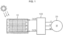
- Fig. 1 is a view illustrating the configuration of connection between a solar power system 10, a motor pump 20 and an inverter 100 according to one embodiment of the present invention.
- Fig. 2 is a view illustrating the configuration of the inverter 100 according to one embodiment of the present invention.
- the inverter 100 is configured to receive DC power generated in the solar power system 10 at its DC links DCP and DCN, convert the received DC power into AC power of a three-phase voltage, and output the AC power to the motor 20. More specifically, the DC links DCP and DCN formed in one side of the inverter 100 are connected to the solar power system 10 and a DC link voltage Vdc is applied to the DC links DCP and DCN. The AC power of the three-phase voltage is output from the other side of the inverter 100 to the motor 20.
- the solar power system 10 may be a power generator which includes a solar cell array (PV-array) consisting of a plurality of solar cells connected in series/parallel and supplies DC power generated from the solar cell array (PV-array) to the inverter 100.
- PV-array solar cell array
- the motor 20 may be an electric motor used for a water pump which pumps water up from low to high points.
- the solar power system 10 and the motor 20 are those generally used in the whole industry and are not particularly limited.
- the inverter 100 may include a measurement part 110, a conversion part 120 and a control part 130.
- the inverter 100 shown in Fig. 2 is just illustrative and elements thereof are not limited to those shown in Fig. 2 but may be partially added, changed or deleted as necessary.
- the measurement part 110 measures a DC link voltage Vdc applied from the solar power system 10 to the DC links DCP and DCN.
- a DC link capacitor for smoothing DC power generated from the solar power system 10 and storing the smoothed DC power as the DC link voltage Vdc may be connected to the DC links DCP and DCN of the inverter 100.
- the DC link voltage Vdc supplied from the solar power system 10 and applied to the DC links DCP and DCN is nonlinearly changed depending on an output W of the motor 20.
- the output W of the motor 20 may be increased in proportion to the square of the increased output frequency f.
- the DC link voltage Vdc measured by the measurement part 110 may be decreased with the increase in output W of the motor 20.
- the measurement part 110 may measure the DC link voltage Vdc stored in the DC link capacitor through a voltage sensor and transmit the measured DC link voltage Vdc to the control part 130 to be described later.
- the conversion part 120 converts the DC link voltage Vdc into a three-phase voltage and outputs the three-phase voltage to the motor 20. More specifically, the conversion part 120 can drive the motor 20 by switching the DC link voltage Vdc smoothed and stored by the DC link capacitor to be converted into the three-phase voltage and outputting the three-phase voltage to the motor 20.
- the conversion part 120 may include a switching circuit consisting of a plurality of switching elements and diodes.
- the conversion part 120 can apply the DC link voltage Vdc to the switching circuit and convert the DC link voltage Vdc into the three-phase voltage by controlling the turn-on/off of the plurality of switching elements.
- the switching elements may be insulated gate bipolar transistors (IGBTs) but are not limited thereto.
- IGBTs insulated gate bipolar transistors
- the conversion part 120 uses the switching circuit to convert the DC link voltage Vdc into the three-phase voltage.
- the conversion part 120 may employ other voltage conversion methods such as a voltage reference inverting method, a vector control method, a VF control method and the like as long as they can converting the DC link voltage Vdc into the three-phase voltage.
- Fig. 3 is a graph showing a change in output frequency f of a three-phase voltage output from the inverter 100 according to one embodiment of the present invention to the motor 20 with time.
- Fig. 4 is a graph showing a change in DC link voltage Vdc applied to the DC links DCP and DCN of the inverter 100 according to one embodiment of the present invention with time.
- Fig. 5 is a graph showing a change in output of the motor 20 driven by a three-phase voltage supplied from the inverter 100 according to one embodiment of the present invention with time.
- control part 130 will be described with reference to Figs. 3 to 5 .
- the control part 130 compares the DC link voltage Vdc with the minimum operating voltage Vmin and adjusts the output frequency f of the three-phase voltage based on a result of the comparison.
- control part 130 can adjust the output frequency f of the three-phase voltage by controlling a turn-on/off operation of the plurality of switching elements included in the conversion part 120 in response to the three-phase voltage output frequency f to be adjusted.
- control part 130 adjusts the output frequency f of the three-phase voltage to the minimum operating frequency fmin.
- the minimum operating frequency fmin may refer to the minimum frequency value of the three-phase voltage supplied to the motor 20 to be driven. That is, the motor 20 begins to be driven when the output frequency f of the three-phase voltage supplied to the motor is equal to or higher than the minimum operating frequency fmin.
- the minimum operating frequency fmin may be set differently depending on the rated specifications of the motor 20.
- the output W of the motor 20 may be "0" since the motor 20 is not driven, as shown Fig. 5 .
- the DC link voltage Vdc may not be changed.
- control part 130 can adjust a hydraulic pressure of a pump actuated by the motor 20 to a predetermined hydraulic pressure or more by driving while keeping the output frequency f of the three-phase voltage supplied to the motor 20 for a predetermined period of time.
- the predetermined period of time may be varied depending on the pump installation environments.
- control part 130 compares the DC link voltage Vdc with the minimum operating voltage Vmin of the motor 20 after the predetermined period of time and increases the output frequency f of the three-phase voltage by a first frequency or decreases it by a second frequency based on a result of the comparison.
- the control part 130 can increase the output frequency f of the three-phase voltage by the first frequency.
- the control part 130 can decrease the output frequency f of the three-phase voltage by the second frequency.
- the minimum operating voltage Vmin may be a minimum voltage value of the voltage supplied to drive the motor 20.
- the minimum operating voltage Vmin may be set differently depending on the rated specifications of the motor 20.
- the first frequency may be set as a frequency value to minimize a rapid change in the DC link voltage Vdc, which may be caused by the adjustment of the output frequency f.
- the first frequency may be 5Hz.
- the first and second frequencies may be frequencies proportional to a preset constant.
- the first frequency may be twice as high as the second frequency.
- the control part 130 can delay a time of a change in the output W of the motor 20 and the DC link voltage Vdc, which may be caused by the change in the output frequency f, by keeping the adjusted output frequency f for a preset waiting time after the adjustment of the output frequency f of the three-phase voltage.
- control part 130 increases the output frequency f of the three-phase voltage by the first frequency during a t1 to t2 interval and compares the DC link voltage Vdc, which is decreased with the increase in the output frequency f of the three-phase voltage, with the minimum operating voltage Vmin.
- the control part 130 increases the output frequency f of the three-phase voltage by the first frequency until point t2.
- the control part 130 decreases the output frequency f of the three-phase voltage by the second frequency.
- the control part 130 may repeat the above-described comparison between the DC link voltage Vdc and the minimum operating voltage Vmin and adjust the output frequency f of the three-phase voltage based on a result of the repeated comparison. Accordingly, the control part 130 can adjust the output frequency f of the three-phase voltage to the maximum while keeping an operating state where the DC link voltage Vdc exceeds the minimum operating voltage Vmin, such as during an interval after point t2. Accordingly, as shown in Fig. 5 , the output W of the motor 20 can be kept at the maximum during the interval after point t2.
- the inverter 100 can drive the motor 20 driven by electric energy of the solar power system 10 with the maximum power without using a separate controller and PID module for calculating a maximum power point tracking (MPPT) algorithm.
- MPPT maximum power point tracking
- the inverter 100 can reduce an installation space and production costs which are required by a controller for calculating the MPPT algorithm and utilize a PID module for control of variables such as a flow rate, a pressure and the like used for a pump.
- the control part 130 can keep the output frequency f of the three-phase voltage at the present frequency during a predetermined keeping period of time.
- control part 130 may again compare the DC link voltage Vdc with the minimum operating voltage Vmin after keeping the output frequency f of the three-phase voltage at the present frequency during the predetermined keeping period of time.
- control part 130 can increase a period of time during which the motor 20 is driven with the maximum power.
Landscapes
- Engineering & Computer Science (AREA)
- Power Engineering (AREA)
- Inverter Devices (AREA)
Abstract
Description
- The present invention relates to an inverter and more particularly, to an inverter which is capable of adjusting an output frequency of a three-phase voltage output to a motor based on a result of comparison in magnitude between the minimum operating voltage of the motor and a DC link voltage applied to a DC link.
- Among alternative energy sources in the future, a solar power system for converting solar energy into electric energy is in the most limelight. The solar power system is to condense sunlight through solar cells, generate electric power using an electric charge difference, and store the electric power in a battery. The electric power is converted from DC power to AC power by means of an inverter and is supplied to a load.
- Such a solar power system has advantages in that it can obtain high energy efficiency only with sunlight without any separate fuel and can be used semi-permanently although it requires high initial facility costs.
- Accordingly, the solar power system is being used, e.g., as a power supply system for a pump installed to supply water for drinking, fields, livestock farming and so on in remote areas where it is difficult to supply power.
- Electric energy generated from solar cells has electrical characteristics significantly different from those of the traditional electric energy. More specifically, since the traditional electric energy has the linear voltage source characteristics, it maintains a constant voltage and works stably when a linear or nonlinear load is applied to a load stage.
- In addition, since it has a single operating point, it always works stably under any input/output conditions. That is, when the electric energy having the linear voltage source is used, it is possible to obtain desired operation conditions irrespective of load conditions.
- However, the electric energy generated from solar cells has the characteristics that a voltage and a current are nonlinearly varied depending on power output to a load through an inverter as a nonlinear voltage source.
- Accordingly, conventionally, in order to control the output of the solar cells to the maximum, a maximum power point tracking (MPPT) algorithm was used to control an output voltage of the solar cells.
- More specifically, conventionally, a controller for driving the MPPT algorithm and an inverter were separately provided and used to generate a control voltage value for controlling the output of the solar cells to the maximum by inputting an output voltage and output current of the solar cells to the MPPT algorithm.
- Thereafter, a PID module was used to perform feedback control to allow the output voltage to be kept at the control voltage value, based on an error between the actual output voltage of the solar cells and the control voltage value.
- However, when the above-mentioned MPPT algorithm is applied to an inverter of a pump receiving power from a solar power system, there is a problem that an expensive separate controller for calculating the control voltage value for controlling the output of the solar cells to the maximum has to be provided in addition to the inverter.
- In addition, when the PID module included in the inverter for supplying the converted power to the pump is used to control the output voltage of the solar cells to the control voltage value, there is another problem that it is necessary to perform control of variables required for pump driving, such as a flow rate, a pressure and so on, in addition to the output voltage control, with the limited capability of the PID module included in the inverter.
- It is an aspect of the present invention to provide an inverter which is capable of driving a motor with the maximum power by making comparison in magnitude between a DC link voltage applied to a DC link and the minimum operating voltage of the motor and controlling an output frequency of a three-phase voltage output to the motor based on a result of the comparison.
- The present invention is not limited to the above aspect and other aspects of the present invention will be clearly understood by those skilled in the art from the following description. The above and/or other aspects and advantages of the present invention will become apparent and more readily appreciated from the following description of the embodiments, taken in conjunction with the accompanying drawings. It should be understood that the objects and advantages of the present invention can be realized by features and combinations thereof set forth in the claims,
- In accordance with one aspect of the present invention, there is provided an inverter including: a measurement part configured to measure a DC link voltage applied to a DC link; a conversion part configured to convert the DC link voltage into a three-phase voltage and output the three-phase voltage to the motor; and a control part configured to make comparison in magnitude between the DC link voltage and the minimum operating voltage of the motor and adjust an output frequency of the three-phase voltage based on a result of the comparison.
- According to the present invention, it is possible to drive a motor with the maximum power by making comparison in magnitude between a DC link voltage applied to a DC link and the minimum operating voltage of the motor and controlling an output frequency of a three-phase voltage output to the motor based on a result of the comparison.
- In addition, according to the present invention, by eliminating a need for a separate controller for calculating a (maximum power point tracking (MPPT) algorithm to drive the motor with the maximum power, it is possible to drive the motor with the maximum power using only the inverter and reduce an installation space and production costs which are required by the separate controller.
- Furthermore, according to the present invention, since the motor can be driven with the maximum power using only the inverter without a PID module, it is possible to utilize the PID module for control of variables required to drive the motor, such as a flow rate, a pressure and the like.
-
-
Fig. 1 is a view illustrating the configuration of connection between a solar power system, a motor pump and an inverter according to one embodiment of the present invention. -
Fig. 2 is a view illustrating the configuration of the inverter according to one embodiment of the present invention. -
Fig. 3 is a graph showing a change in output frequency of a three-phase voltage output from the inverter according to one embodiment of the present invention to a motor with time. -
Fig. 4 is a graph showing a change in DC link voltage applied to DC links of the inverter according to one embodiment of the present invention with time. -
Fig. 5 is a graph showing a change in output of the motor driven by a three-phase voltage supplied from the inverter according to one embodiment of the present invention with time. - The above objects, features and advantages will become more clearly apparent from the following detailed description in conjunction with the accompanying drawings. Therefore, the technical ideas of the present invention can be easily understood and practiced by those skilled in the art. In the following detailed description of the present invention, concrete description on related functions or constructions will be omitted if it is deemed that the functions and/or constructions may unnecessarily obscure the gist of the present invention. Hereinafter, preferred embodiments of the present invention will be described in detail with reference to the accompanying drawings. Throughout the drawings, the same or similar elements are denoted by the same reference numerals.
-
Fig. 1 is a view illustrating the configuration of connection between a solar power system 10, a motor pump 20 and aninverter 100 according to one embodiment of the present invention.Fig. 2 is a view illustrating the configuration of theinverter 100 according to one embodiment of the present invention. - Referring to
Fig. 1 , theinverter 100 according to one embodiment of the present invention is configured to receive DC power generated in the solar power system 10 at its DC links DCP and DCN, convert the received DC power into AC power of a three-phase voltage, and output the AC power to the motor 20. More specifically, the DC links DCP and DCN formed in one side of theinverter 100 are connected to the solar power system 10 and a DC link voltage Vdc is applied to the DC links DCP and DCN. The AC power of the three-phase voltage is output from the other side of theinverter 100 to the motor 20. - In this embodiment, the solar power system 10 may be a power generator which includes a solar cell array (PV-array) consisting of a plurality of solar cells connected in series/parallel and supplies DC power generated from the solar cell array (PV-array) to the
inverter 100. - In addition, the motor 20 may be an electric motor used for a water pump which pumps water up from low to high points.
- It is here noted that the solar power system 10 and the motor 20 are those generally used in the whole industry and are not particularly limited.
- Referring to
Fig. 2 , theinverter 100 according to one embodiment of the present invention may include ameasurement part 110, aconversion part 120 and acontrol part 130. Theinverter 100 shown inFig. 2 is just illustrative and elements thereof are not limited to those shown inFig. 2 but may be partially added, changed or deleted as necessary. - The
measurement part 110 measures a DC link voltage Vdc applied from the solar power system 10 to the DC links DCP and DCN. In this embodiment, although not shown in the figure, a DC link capacitor for smoothing DC power generated from the solar power system 10 and storing the smoothed DC power as the DC link voltage Vdc may be connected to the DC links DCP and DCN of theinverter 100. - The DC link voltage Vdc supplied from the solar power system 10 and applied to the DC links DCP and DCN is nonlinearly changed depending on an output W of the motor 20.
- In more detail, when the output frequency f of a three-phase voltage converted by the
inverter 100 and supplied to the motor 20 is increased under control of theinverter 100, the output W of the motor 20 may be increased in proportion to the square of the increased output frequency f. In addition, the DC link voltage Vdc measured by themeasurement part 110 may be decreased with the increase in output W of the motor 20. - The
measurement part 110 may measure the DC link voltage Vdc stored in the DC link capacitor through a voltage sensor and transmit the measured DC link voltage Vdc to thecontrol part 130 to be described later. - The
conversion part 120 converts the DC link voltage Vdc into a three-phase voltage and outputs the three-phase voltage to the motor 20. More specifically, theconversion part 120 can drive the motor 20 by switching the DC link voltage Vdc smoothed and stored by the DC link capacitor to be converted into the three-phase voltage and outputting the three-phase voltage to the motor 20. - To this end, in one embodiment, the
conversion part 120 may include a switching circuit consisting of a plurality of switching elements and diodes. Theconversion part 120 can apply the DC link voltage Vdc to the switching circuit and convert the DC link voltage Vdc into the three-phase voltage by controlling the turn-on/off of the plurality of switching elements. - In this embodiment, the switching elements may be insulated gate bipolar transistors (IGBTs) but are not limited thereto.
- It has been illustrated in the above that the
conversion part 120 uses the switching circuit to convert the DC link voltage Vdc into the three-phase voltage. However, theconversion part 120 may employ other voltage conversion methods such as a voltage reference inverting method, a vector control method, a VF control method and the like as long as they can converting the DC link voltage Vdc into the three-phase voltage. -
Fig. 3 is a graph showing a change in output frequency f of a three-phase voltage output from theinverter 100 according to one embodiment of the present invention to the motor 20 with time.Fig. 4 is a graph showing a change in DC link voltage Vdc applied to the DC links DCP and DCN of theinverter 100 according to one embodiment of the present invention with time.Fig. 5 is a graph showing a change in output of the motor 20 driven by a three-phase voltage supplied from theinverter 100 according to one embodiment of the present invention with time. - Hereinafter, the
control part 130 will be described with reference toFigs. 3 to 5 . - The
control part 130 compares the DC link voltage Vdc with the minimum operating voltage Vmin and adjusts the output frequency f of the three-phase voltage based on a result of the comparison. - At this time, the
control part 130 can adjust the output frequency f of the three-phase voltage by controlling a turn-on/off operation of the plurality of switching elements included in theconversion part 120 in response to the three-phase voltage output frequency f to be adjusted. - In addition, at the time of start of the operation of the motor 20, the
control part 130 adjusts the output frequency f of the three-phase voltage to the minimum operating frequency fmin. - Here, the minimum operating frequency fmin may refer to the minimum frequency value of the three-phase voltage supplied to the motor 20 to be driven. That is, the motor 20 begins to be driven when the output frequency f of the three-phase voltage supplied to the motor is equal to or higher than the minimum operating frequency fmin.
- At this time, the minimum operating frequency fmin may be set differently depending on the rated specifications of the motor 20.
- In a t0 to t1 interval from during which the three-phase voltage whose output frequency f is lower than the minimum operating frequency fmin, as shown in
Fig. 3 , the output W of the motor 20 may be "0" since the motor 20 is not driven, as shownFig. 5 . - In addition, as shown in
Fig. 4 , since the three-phase voltage whose output frequency f is lower than the minimum operating frequency fmin is supplied to the motor 20 to prevent the motor 200 from being driven, the DC link voltage Vdc may not be changed. - Thereafter, at the point t1 at which the
control part 130 adjusts the output frequency f of the three-phase voltage to the minimum operation frequency fmin, as the motor 20 begins to be driven, the DC voltage Vdc begins to decrease. - At this time, the
control part 130 can adjust a hydraulic pressure of a pump actuated by the motor 20 to a predetermined hydraulic pressure or more by driving while keeping the output frequency f of the three-phase voltage supplied to the motor 20 for a predetermined period of time. - In this embodiment, the predetermined period of time may be varied depending on the pump installation environments.
- Next, the
control part 130 compares the DC link voltage Vdc with the minimum operating voltage Vmin of the motor 20 after the predetermined period of time and increases the output frequency f of the three-phase voltage by a first frequency or decreases it by a second frequency based on a result of the comparison. - More specifically, as a result of the comparison between the DC link voltage Vdc and the minimum operating voltage Vmin, if the DC link voltage Vdc exceeds the minimum operating voltage Vmin, the
control part 130 can increase the output frequency f of the three-phase voltage by the first frequency. - Conversely, as a result of the comparison between the DC link voltage Vdc and the minimum operating voltage Vmin, if the DC link voltage Vdc is equal to or lower than the minimum operating voltage Vmin, the
control part 130 can decrease the output frequency f of the three-phase voltage by the second frequency. - In this embodiment, the minimum operating voltage Vmin may be a minimum voltage value of the voltage supplied to drive the motor 20. The minimum operating voltage Vmin may be set differently depending on the rated specifications of the motor 20.
- That is, when the DC link voltage Vdc applied to the DC links DCP and DCN is higher than the minimum operating voltage Vmin, the motor 20 can be driven.
- In the meantime, the first frequency may be set as a frequency value to minimize a rapid change in the DC link voltage Vdc, which may be caused by the adjustment of the output frequency f. For example, the first frequency may be 5Hz.
- In addition, the first and second frequencies may be frequencies proportional to a preset constant. For example, the first frequency may be twice as high as the second frequency.
- The
control part 130 can delay a time of a change in the output W of the motor 20 and the DC link voltage Vdc, which may be caused by the change in the output frequency f, by keeping the adjusted output frequency f for a preset waiting time after the adjustment of the output frequency f of the three-phase voltage. - As shown in
Fig. 3 , thecontrol part 130 increases the output frequency f of the three-phase voltage by the first frequency during a t1 to t2 interval and compares the DC link voltage Vdc, which is decreased with the increase in the output frequency f of the three-phase voltage, with the minimum operating voltage Vmin. - As shown in
Fig. 4 , as a result of the comparison between the DC link voltage Vdc and the minimum operating voltage Vmin, since the DC link voltage Vdc exceeds the minimum operating voltage Vmin until point t2, thecontrol part 130 increases the output frequency f of the three-phase voltage by the first frequency until point t2. - Thereafter, from point t2, as a result of the comparison between the DC link voltage Vdc and the minimum operating voltage Vmin, since the DC link voltage Vdc is equal to or lower than the minimum operating voltage Vmin, the
control part 130 decreases the output frequency f of the three-phase voltage by the second frequency. - The
control part 130 may repeat the above-described comparison between the DC link voltage Vdc and the minimum operating voltage Vmin and adjust the output frequency f of the three-phase voltage based on a result of the repeated comparison. Accordingly, thecontrol part 130 can adjust the output frequency f of the three-phase voltage to the maximum while keeping an operating state where the DC link voltage Vdc exceeds the minimum operating voltage Vmin, such as during an interval after point t2. Accordingly, as shown inFig. 5 , the output W of the motor 20 can be kept at the maximum during the interval after point t2. - In other words, the
inverter 100 according to one embodiment of the present invention can drive the motor 20 driven by electric energy of the solar power system 10 with the maximum power without using a separate controller and PID module for calculating a maximum power point tracking (MPPT) algorithm. - As a result, the
inverter 100 according to one embodiment of the present invention can reduce an installation space and production costs which are required by a controller for calculating the MPPT algorithm and utilize a PID module for control of variables such as a flow rate, a pressure and the like used for a pump. - In another embodiment, as a result of the comparison between the DC link voltage Vdc and the minimum operating voltage Vmin, if the DC link voltage Vdc is equal to the minimum operating voltage Vmin, the
control part 130 can keep the output frequency f of the three-phase voltage at the present frequency during a predetermined keeping period of time. - In another embodiment, the
control part 130 may again compare the DC link voltage Vdc with the minimum operating voltage Vmin after keeping the output frequency f of the three-phase voltage at the present frequency during the predetermined keeping period of time. - Thus, the
control part 130 can increase a period of time during which the motor 20 is driven with the maximum power. - While the present invention has been particularly shown and described with reference to exemplary embodiments thereof, it will be understood by those skilled in the art that various changes in form and details may be made therein without departing from the spirit and scope of the present invention. The exemplary embodiments are provided for the purpose of illustrating the invention, not in a limitative sense. Thus, it is intended that the present invention covers the modifications and variations of this invention provided they come within the scope of the appended claims and their equivalents.
Claims (5)
- An inverter for converting power and supplying the power to a motor (20), comprising:a measurement part (110) configured to measure a DC link voltage applied to a DC link;a conversion part (120) configured to convert the DC link voltage into a three-phase voltage and output the three-phase voltage to the motor (20); anda control part (130) configured to make comparison in magnitude between the DC link voltage and the minimum operating voltage of the motor (20) and adjust an output frequency of the three-phase voltage based on a result of the comparison.
- The inverter according to claim 1, wherein the control part (130) adjusts the output frequency to the minimum operating frequency of the motor (20) at the time of start of operation of the motor (20).
- The inverter according to claim 2, wherein, when the output frequency reaches the minimum operating frequency, the control part (130) keeps the output frequency at the minimum operating frequency.
- The inverter according to claim 1, wherein, when the DC link voltage exceeds the minimum operating voltage, the control part (130) increases the output frequency by a first frequency.
- The inverter according to claim 4, wherein, when the DC link voltage is equal to or lower than the minimum operating voltage, the control part (130) decreases the output frequency by a second frequency.
Applications Claiming Priority (1)
| Application Number | Priority Date | Filing Date | Title |
|---|---|---|---|
| KR1020160006061A KR101783121B1 (en) | 2016-01-18 | 2016-01-18 | Inverter |
Publications (2)
| Publication Number | Publication Date |
|---|---|
| EP3193444A1 true EP3193444A1 (en) | 2017-07-19 |
| EP3193444B1 EP3193444B1 (en) | 2020-09-23 |
Family
ID=57321161
Family Applications (1)
| Application Number | Title | Priority Date | Filing Date |
|---|---|---|---|
| EP16198585.8A Active EP3193444B1 (en) | 2016-01-18 | 2016-11-14 | Inverter |
Country Status (6)
| Country | Link |
|---|---|
| US (1) | US11296639B2 (en) |
| EP (1) | EP3193444B1 (en) |
| JP (1) | JP6280976B2 (en) |
| KR (1) | KR101783121B1 (en) |
| CN (1) | CN106982023B (en) |
| ES (1) | ES2833442T3 (en) |
Cited By (1)
| Publication number | Priority date | Publication date | Assignee | Title |
|---|---|---|---|---|
| EP3522364A1 (en) * | 2018-02-01 | 2019-08-07 | LSIS Co., Ltd. | Inverter |
Families Citing this family (5)
| Publication number | Priority date | Publication date | Assignee | Title |
|---|---|---|---|---|
| GB201513549D0 (en) * | 2015-07-31 | 2015-09-16 | Siemens Ag | Inverter |
| KR101881730B1 (en) * | 2016-12-14 | 2018-07-25 | 엘에스산전 주식회사 | Method for controlling inverter in solar pump system |
| KR101999183B1 (en) * | 2018-05-10 | 2019-07-11 | 엘에스산전 주식회사 | Method for controlling inverter in solar pump system |
| ES2753221B2 (en) * | 2019-07-25 | 2020-11-05 | Eos Itr S L | ELECTRICAL CIRCUIT FOR SUPPLYING CENTRIFUGAL PUMPS |
| US20210091709A1 (en) * | 2019-09-20 | 2021-03-25 | Erthos Inc. | Flat Tile Solar Panels |
Citations (2)
| Publication number | Priority date | Publication date | Assignee | Title |
|---|---|---|---|---|
| US6590793B1 (en) * | 1996-08-23 | 2003-07-08 | Canon Kabushiki Kaisha | Electric power supplying apparatus using unstable electric power supply and control method therefor |
| US20140125264A1 (en) * | 2012-11-07 | 2014-05-08 | Toyota Jidosha Kabushiki Kaisha | Control system for ac electric motor |
Family Cites Families (24)
| Publication number | Priority date | Publication date | Assignee | Title |
|---|---|---|---|---|
| JPH05265582A (en) | 1990-06-29 | 1993-10-15 | Tonen Corp | Inverter control system in solar battery driving |
| JPH1164393A (en) | 1997-08-11 | 1999-03-05 | Fuji Electric Co Ltd | Output current display circuit of voltage type inverter |
| US6275403B1 (en) * | 1998-12-31 | 2001-08-14 | Worldwater Corporation | Bias controlled DC to AC converter and systems |
| JP4380906B2 (en) | 2000-10-25 | 2009-12-09 | 株式会社中央製作所 | Power supply voltage / current setting display device |
| US7221121B2 (en) * | 2001-11-23 | 2007-05-22 | Danfoss Drives A/S | Frequency converter for different mains voltages |
| DK174880B1 (en) * | 2001-11-23 | 2004-01-19 | Danfoss Drives As | Procedure for control of frequency converter for various line voltages and a frequency converter |
| JP4581603B2 (en) | 2004-09-29 | 2010-11-17 | パナソニック株式会社 | Electric motor drive |
| KR20070074623A (en) * | 2004-10-29 | 2007-07-12 | 캐리어 코포레이션 | GBS control |
| JP4571480B2 (en) | 2004-11-04 | 2010-10-27 | 本田技研工業株式会社 | Electric motor control device |
| US7336510B2 (en) * | 2005-03-23 | 2008-02-26 | Delphi Technologies, Inc. | Method and system for increasing load start-up capability of a DC-to-AC converter |
| JP4715373B2 (en) | 2005-08-01 | 2011-07-06 | 富士電機システムズ株式会社 | Inverter device |
| US20070290651A1 (en) * | 2006-06-14 | 2007-12-20 | Worldwater & Power Corp. | Solar power control using irradiance |
| CN101841256A (en) * | 2009-03-19 | 2010-09-22 | 孔小明 | Method for tracking and controlling maximum power point of solar power generation |
| US8601828B2 (en) * | 2009-04-29 | 2013-12-10 | Bristol Compressors International, Inc. | Capacity control systems and methods for a compressor |
| US8406022B2 (en) | 2010-04-16 | 2013-03-26 | Samsung Electro-Mechanics Co., Ltd. | Apparatus and method for controling power quality of power generation system |
| US8421397B2 (en) * | 2011-04-11 | 2013-04-16 | Eaton Corporation | System and method for fast start-up of an induction motor |
| JP5646752B2 (en) | 2011-06-28 | 2014-12-24 | 京セラ株式会社 | Grid-connected inverter device and control method thereof |
| KR101236621B1 (en) * | 2011-12-14 | 2013-02-22 | 엘에스산전 주식회사 | Apparatus for controlling inverter |
| US9960703B2 (en) * | 2013-09-06 | 2018-05-01 | Mitsubishi Electric Corporation | DC power-supply device and refrigeration-cycle application device including the same |
| JP6113625B2 (en) * | 2013-10-15 | 2017-04-12 | 住友重機械工業株式会社 | Injection molding machine |
| JP2015116074A (en) | 2013-12-13 | 2015-06-22 | キヤノン株式会社 | Motor control method, motor device and robot |
| CN103762937B (en) * | 2013-12-31 | 2017-01-18 | 深圳易能电气技术股份有限公司 | MPPT photovoltaic inverter control system and control method thereof |
| JP2015208106A (en) * | 2014-04-21 | 2015-11-19 | アール・ビー・コントロールズ株式会社 | Motor drive device |
| DK3362867T3 (en) * | 2015-10-13 | 2021-10-18 | Premier Energy Holdings Inc | MAXIMUM-POWER-POINT-TRACKING WITH VARIABLE SPEED, SOLAR ELECTRIC MOTOR CONTROLLER FOR INDUCTION AND PERMANENT POWER AC MOTORS |
-
2016
- 2016-01-18 KR KR1020160006061A patent/KR101783121B1/en active Active
- 2016-11-14 ES ES16198585T patent/ES2833442T3/en active Active
- 2016-11-14 EP EP16198585.8A patent/EP3193444B1/en active Active
- 2016-11-22 JP JP2016226573A patent/JP6280976B2/en active Active
- 2016-11-23 CN CN201611037881.XA patent/CN106982023B/en active Active
- 2016-12-20 US US15/384,883 patent/US11296639B2/en active Active
Patent Citations (2)
| Publication number | Priority date | Publication date | Assignee | Title |
|---|---|---|---|---|
| US6590793B1 (en) * | 1996-08-23 | 2003-07-08 | Canon Kabushiki Kaisha | Electric power supplying apparatus using unstable electric power supply and control method therefor |
| US20140125264A1 (en) * | 2012-11-07 | 2014-05-08 | Toyota Jidosha Kabushiki Kaisha | Control system for ac electric motor |
Cited By (1)
| Publication number | Priority date | Publication date | Assignee | Title |
|---|---|---|---|---|
| EP3522364A1 (en) * | 2018-02-01 | 2019-08-07 | LSIS Co., Ltd. | Inverter |
Also Published As
| Publication number | Publication date |
|---|---|
| US20170207741A1 (en) | 2017-07-20 |
| EP3193444B1 (en) | 2020-09-23 |
| KR101783121B1 (en) | 2017-09-28 |
| ES2833442T3 (en) | 2021-06-15 |
| JP2017131095A (en) | 2017-07-27 |
| US11296639B2 (en) | 2022-04-05 |
| CN106982023B (en) | 2019-05-31 |
| CN106982023A (en) | 2017-07-25 |
| JP6280976B2 (en) | 2018-02-14 |
| KR20170086342A (en) | 2017-07-26 |
Similar Documents
| Publication | Publication Date | Title |
|---|---|---|
| EP3193444B1 (en) | Inverter | |
| KR100908156B1 (en) | Solar maximum power tracking device and method | |
| CN102170241B (en) | System and method for a single stage power conversion system | |
| US20170310229A1 (en) | Dc-to-dc converter, power converter, power generation system, and method for dc-to-dc conversion | |
| US10030632B2 (en) | Control device for voltage source converter and operating method thereof | |
| US10193347B2 (en) | Method and apparatus for improved burst mode during power conversion | |
| JP6291111B2 (en) | Solar inverter | |
| JPWO2011135658A1 (en) | Grid-connected inverter | |
| CN106030956A (en) | Two-stage inverter device for energy conversion system and control method thereof | |
| KR101484064B1 (en) | Power management device for new Renewable Energy | |
| EP2670033B1 (en) | Starting of photovoltaic system | |
| WO2015145971A1 (en) | Power conversion device and power conversion method | |
| US10581340B2 (en) | Solar drive system and method for tracking the maximum power point of a photovoltaic array | |
| CN105359051B (en) | The control system of solar power system and control method | |
| KR102285990B1 (en) | Multi-directional balancing DC converter control system for solar cell generation power optimization | |
| KR101382946B1 (en) | Photovoltaic power generation system and control method thereof | |
| KR20100098870A (en) | Photovoltaic power generation system, apparatus and method for tracking maximum power point | |
| KR101305634B1 (en) | Photovoltaic power generation system and control method thereof | |
| KR101561640B1 (en) | Micro converter device using power deviation handling of needless high-voltage DC-DC converter and control method thereof | |
| KR101349479B1 (en) | Photovoltaic power generation system and control method thereof | |
| KR101360539B1 (en) | Photovoltaic power generation system and control method thereof | |
| KR102114298B1 (en) | Pulse Width Modulation Dead Time Control Method for High Efficient Inverter of Energy Storage System | |
| KR100917307B1 (en) | Independent power supply system using solar cell for pumping motor pump | |
| WO2015170143A1 (en) | Configurable inverter apparatus, photovoltaic system comprising such an inverter apparatus | |
| KR20200056970A (en) | Pulse Width Modulation Dead Time Control Method for High Efficient Inverter of Energy Storage System |
Legal Events
| Date | Code | Title | Description |
|---|---|---|---|
| PUAI | Public reference made under article 153(3) epc to a published international application that has entered the european phase |
Free format text: ORIGINAL CODE: 0009012 |
|
| STAA | Information on the status of an ep patent application or granted ep patent |
Free format text: STATUS: THE APPLICATION HAS BEEN PUBLISHED |
|
| AK | Designated contracting states |
Kind code of ref document: A1 Designated state(s): AL AT BE BG CH CY CZ DE DK EE ES FI FR GB GR HR HU IE IS IT LI LT LU LV MC MK MT NL NO PL PT RO RS SE SI SK SM TR |
|
| AX | Request for extension of the european patent |
Extension state: BA ME |
|
| STAA | Information on the status of an ep patent application or granted ep patent |
Free format text: STATUS: REQUEST FOR EXAMINATION WAS MADE |
|
| 17P | Request for examination filed |
Effective date: 20180118 |
|
| RBV | Designated contracting states (corrected) |
Designated state(s): AL AT BE BG CH CY CZ DE DK EE ES FI FR GB GR HR HU IE IS IT LI LT LU LV MC MK MT NL NO PL PT RO RS SE SI SK SM TR |
|
| RIC1 | Information provided on ipc code assigned before grant |
Ipc: H02P 27/06 20060101AFI20200218BHEP |
|
| GRAP | Despatch of communication of intention to grant a patent |
Free format text: ORIGINAL CODE: EPIDOSNIGR1 |
|
| STAA | Information on the status of an ep patent application or granted ep patent |
Free format text: STATUS: GRANT OF PATENT IS INTENDED |
|
| INTG | Intention to grant announced |
Effective date: 20200514 |
|
| GRAS | Grant fee paid |
Free format text: ORIGINAL CODE: EPIDOSNIGR3 |
|
| GRAA | (expected) grant |
Free format text: ORIGINAL CODE: 0009210 |
|
| STAA | Information on the status of an ep patent application or granted ep patent |
Free format text: STATUS: THE PATENT HAS BEEN GRANTED |
|
| AK | Designated contracting states |
Kind code of ref document: B1 Designated state(s): AL AT BE BG CH CY CZ DE DK EE ES FI FR GB GR HR HU IE IS IT LI LT LU LV MC MK MT NL NO PL PT RO RS SE SI SK SM TR |
|
| REG | Reference to a national code |
Ref country code: GB Ref legal event code: FG4D |
|
| REG | Reference to a national code |
Ref country code: CH Ref legal event code: EP |
|
| REG | Reference to a national code |
Ref country code: DE Ref legal event code: R096 Ref document number: 602016044432 Country of ref document: DE |
|
| REG | Reference to a national code |
Ref country code: IE Ref legal event code: FG4D |
|
| REG | Reference to a national code |
Ref country code: AT Ref legal event code: REF Ref document number: 1317408 Country of ref document: AT Kind code of ref document: T Effective date: 20201015 |
|
| PG25 | Lapsed in a contracting state [announced via postgrant information from national office to epo] |
Ref country code: HR Free format text: LAPSE BECAUSE OF FAILURE TO SUBMIT A TRANSLATION OF THE DESCRIPTION OR TO PAY THE FEE WITHIN THE PRESCRIBED TIME-LIMIT Effective date: 20200923 Ref country code: BG Free format text: LAPSE BECAUSE OF FAILURE TO SUBMIT A TRANSLATION OF THE DESCRIPTION OR TO PAY THE FEE WITHIN THE PRESCRIBED TIME-LIMIT Effective date: 20201223 Ref country code: NO Free format text: LAPSE BECAUSE OF FAILURE TO SUBMIT A TRANSLATION OF THE DESCRIPTION OR TO PAY THE FEE WITHIN THE PRESCRIBED TIME-LIMIT Effective date: 20201223 Ref country code: FI Free format text: LAPSE BECAUSE OF FAILURE TO SUBMIT A TRANSLATION OF THE DESCRIPTION OR TO PAY THE FEE WITHIN THE PRESCRIBED TIME-LIMIT Effective date: 20200923 Ref country code: GR Free format text: LAPSE BECAUSE OF FAILURE TO SUBMIT A TRANSLATION OF THE DESCRIPTION OR TO PAY THE FEE WITHIN THE PRESCRIBED TIME-LIMIT Effective date: 20201224 Ref country code: SE Free format text: LAPSE BECAUSE OF FAILURE TO SUBMIT A TRANSLATION OF THE DESCRIPTION OR TO PAY THE FEE WITHIN THE PRESCRIBED TIME-LIMIT Effective date: 20200923 |
|
| REG | Reference to a national code |
Ref country code: AT Ref legal event code: MK05 Ref document number: 1317408 Country of ref document: AT Kind code of ref document: T Effective date: 20200923 |
|
| PG25 | Lapsed in a contracting state [announced via postgrant information from national office to epo] |
Ref country code: LV Free format text: LAPSE BECAUSE OF FAILURE TO SUBMIT A TRANSLATION OF THE DESCRIPTION OR TO PAY THE FEE WITHIN THE PRESCRIBED TIME-LIMIT Effective date: 20200923 Ref country code: RS Free format text: LAPSE BECAUSE OF FAILURE TO SUBMIT A TRANSLATION OF THE DESCRIPTION OR TO PAY THE FEE WITHIN THE PRESCRIBED TIME-LIMIT Effective date: 20200923 |
|
| REG | Reference to a national code |
Ref country code: NL Ref legal event code: MP Effective date: 20200923 |
|
| REG | Reference to a national code |
Ref country code: LT Ref legal event code: MG4D |
|
| PG25 | Lapsed in a contracting state [announced via postgrant information from national office to epo] |
Ref country code: EE Free format text: LAPSE BECAUSE OF FAILURE TO SUBMIT A TRANSLATION OF THE DESCRIPTION OR TO PAY THE FEE WITHIN THE PRESCRIBED TIME-LIMIT Effective date: 20200923 Ref country code: PT Free format text: LAPSE BECAUSE OF FAILURE TO SUBMIT A TRANSLATION OF THE DESCRIPTION OR TO PAY THE FEE WITHIN THE PRESCRIBED TIME-LIMIT Effective date: 20210125 Ref country code: RO Free format text: LAPSE BECAUSE OF FAILURE TO SUBMIT A TRANSLATION OF THE DESCRIPTION OR TO PAY THE FEE WITHIN THE PRESCRIBED TIME-LIMIT Effective date: 20200923 Ref country code: SM Free format text: LAPSE BECAUSE OF FAILURE TO SUBMIT A TRANSLATION OF THE DESCRIPTION OR TO PAY THE FEE WITHIN THE PRESCRIBED TIME-LIMIT Effective date: 20200923 Ref country code: CZ Free format text: LAPSE BECAUSE OF FAILURE TO SUBMIT A TRANSLATION OF THE DESCRIPTION OR TO PAY THE FEE WITHIN THE PRESCRIBED TIME-LIMIT Effective date: 20200923 Ref country code: LT Free format text: LAPSE BECAUSE OF FAILURE TO SUBMIT A TRANSLATION OF THE DESCRIPTION OR TO PAY THE FEE WITHIN THE PRESCRIBED TIME-LIMIT Effective date: 20200923 |
|
| PG25 | Lapsed in a contracting state [announced via postgrant information from national office to epo] |
Ref country code: IS Free format text: LAPSE BECAUSE OF FAILURE TO SUBMIT A TRANSLATION OF THE DESCRIPTION OR TO PAY THE FEE WITHIN THE PRESCRIBED TIME-LIMIT Effective date: 20210123 Ref country code: PL Free format text: LAPSE BECAUSE OF FAILURE TO SUBMIT A TRANSLATION OF THE DESCRIPTION OR TO PAY THE FEE WITHIN THE PRESCRIBED TIME-LIMIT Effective date: 20200923 Ref country code: AT Free format text: LAPSE BECAUSE OF FAILURE TO SUBMIT A TRANSLATION OF THE DESCRIPTION OR TO PAY THE FEE WITHIN THE PRESCRIBED TIME-LIMIT Effective date: 20200923 Ref country code: AL Free format text: LAPSE BECAUSE OF FAILURE TO SUBMIT A TRANSLATION OF THE DESCRIPTION OR TO PAY THE FEE WITHIN THE PRESCRIBED TIME-LIMIT Effective date: 20200923 |
|
| REG | Reference to a national code |
Ref country code: ES Ref legal event code: FG2A Ref document number: 2833442 Country of ref document: ES Kind code of ref document: T3 Effective date: 20210615 |
|
| REG | Reference to a national code |
Ref country code: DE Ref legal event code: R097 Ref document number: 602016044432 Country of ref document: DE |
|
| PG25 | Lapsed in a contracting state [announced via postgrant information from national office to epo] |
Ref country code: MC Free format text: LAPSE BECAUSE OF FAILURE TO SUBMIT A TRANSLATION OF THE DESCRIPTION OR TO PAY THE FEE WITHIN THE PRESCRIBED TIME-LIMIT Effective date: 20200923 Ref country code: SK Free format text: LAPSE BECAUSE OF FAILURE TO SUBMIT A TRANSLATION OF THE DESCRIPTION OR TO PAY THE FEE WITHIN THE PRESCRIBED TIME-LIMIT Effective date: 20200923 |
|
| REG | Reference to a national code |
Ref country code: CH Ref legal event code: PL |
|
| PG25 | Lapsed in a contracting state [announced via postgrant information from national office to epo] |
Ref country code: LU Free format text: LAPSE BECAUSE OF NON-PAYMENT OF DUE FEES Effective date: 20201114 |
|
| PLBE | No opposition filed within time limit |
Free format text: ORIGINAL CODE: 0009261 |
|
| STAA | Information on the status of an ep patent application or granted ep patent |
Free format text: STATUS: NO OPPOSITION FILED WITHIN TIME LIMIT |
|
| REG | Reference to a national code |
Ref country code: BE Ref legal event code: MM Effective date: 20201130 |
|
| PG25 | Lapsed in a contracting state [announced via postgrant information from national office to epo] |
Ref country code: DK Free format text: LAPSE BECAUSE OF FAILURE TO SUBMIT A TRANSLATION OF THE DESCRIPTION OR TO PAY THE FEE WITHIN THE PRESCRIBED TIME-LIMIT Effective date: 20200923 Ref country code: CH Free format text: LAPSE BECAUSE OF NON-PAYMENT OF DUE FEES Effective date: 20201130 Ref country code: SI Free format text: LAPSE BECAUSE OF FAILURE TO SUBMIT A TRANSLATION OF THE DESCRIPTION OR TO PAY THE FEE WITHIN THE PRESCRIBED TIME-LIMIT Effective date: 20200923 Ref country code: LI Free format text: LAPSE BECAUSE OF NON-PAYMENT OF DUE FEES Effective date: 20201130 |
|
| 26N | No opposition filed |
Effective date: 20210624 |
|
| PG25 | Lapsed in a contracting state [announced via postgrant information from national office to epo] |
Ref country code: IE Free format text: LAPSE BECAUSE OF NON-PAYMENT OF DUE FEES Effective date: 20201114 |
|
| PG25 | Lapsed in a contracting state [announced via postgrant information from national office to epo] |
Ref country code: TR Free format text: LAPSE BECAUSE OF FAILURE TO SUBMIT A TRANSLATION OF THE DESCRIPTION OR TO PAY THE FEE WITHIN THE PRESCRIBED TIME-LIMIT Effective date: 20200923 Ref country code: MT Free format text: LAPSE BECAUSE OF FAILURE TO SUBMIT A TRANSLATION OF THE DESCRIPTION OR TO PAY THE FEE WITHIN THE PRESCRIBED TIME-LIMIT Effective date: 20200923 Ref country code: CY Free format text: LAPSE BECAUSE OF FAILURE TO SUBMIT A TRANSLATION OF THE DESCRIPTION OR TO PAY THE FEE WITHIN THE PRESCRIBED TIME-LIMIT Effective date: 20200923 |
|
| PG25 | Lapsed in a contracting state [announced via postgrant information from national office to epo] |
Ref country code: MK Free format text: LAPSE BECAUSE OF FAILURE TO SUBMIT A TRANSLATION OF THE DESCRIPTION OR TO PAY THE FEE WITHIN THE PRESCRIBED TIME-LIMIT Effective date: 20200923 |
|
| PG25 | Lapsed in a contracting state [announced via postgrant information from national office to epo] |
Ref country code: BE Free format text: LAPSE BECAUSE OF NON-PAYMENT OF DUE FEES Effective date: 20201130 |
|
| PG25 | Lapsed in a contracting state [announced via postgrant information from national office to epo] |
Ref country code: NL Free format text: LAPSE BECAUSE OF NON-PAYMENT OF DUE FEES Effective date: 20200923 |
|
| P01 | Opt-out of the competence of the unified patent court (upc) registered |
Effective date: 20230625 |
|
| PGFP | Annual fee paid to national office [announced via postgrant information from national office to epo] |
Ref country code: IT Payment date: 20250909 Year of fee payment: 10 |
|
| PGFP | Annual fee paid to national office [announced via postgrant information from national office to epo] |
Ref country code: GB Payment date: 20250909 Year of fee payment: 10 |
|
| PGFP | Annual fee paid to national office [announced via postgrant information from national office to epo] |
Ref country code: FR Payment date: 20250909 Year of fee payment: 10 |
|
| PGFP | Annual fee paid to national office [announced via postgrant information from national office to epo] |
Ref country code: DE Payment date: 20250908 Year of fee payment: 10 |
|
| PGFP | Annual fee paid to national office [announced via postgrant information from national office to epo] |
Ref country code: ES Payment date: 20251215 Year of fee payment: 10 |