EP3193230A1 - Compensateur activé par le pilote sur aéronef à commande électrique - Google Patents
Compensateur activé par le pilote sur aéronef à commande électrique Download PDFInfo
- Publication number
- EP3193230A1 EP3193230A1 EP17151148.8A EP17151148A EP3193230A1 EP 3193230 A1 EP3193230 A1 EP 3193230A1 EP 17151148 A EP17151148 A EP 17151148A EP 3193230 A1 EP3193230 A1 EP 3193230A1
- Authority
- EP
- European Patent Office
- Prior art keywords
- aircraft
- control
- trim
- mode
- function
- Prior art date
- Legal status (The legal status is an assumption and is not a legal conclusion. Google has not performed a legal analysis and makes no representation as to the accuracy of the status listed.)
- Granted
Links
- 238000000034 method Methods 0.000 claims abstract description 12
- 230000007704 transition Effects 0.000 claims abstract description 12
- 125000004122 cyclic group Chemical group 0.000 claims description 19
- 230000003213 activating effect Effects 0.000 claims description 12
- 230000000881 depressing effect Effects 0.000 claims description 3
- 230000001052 transient effect Effects 0.000 abstract description 7
- RZVHIXYEVGDQDX-UHFFFAOYSA-N 9,10-anthraquinone Chemical compound C1=CC=C2C(=O)C3=CC=CC=C3C(=O)C2=C1 RZVHIXYEVGDQDX-UHFFFAOYSA-N 0.000 description 17
- 230000004044 response Effects 0.000 description 8
- 230000008901 benefit Effects 0.000 description 3
- 230000008859 change Effects 0.000 description 3
- 235000015842 Hesperis Nutrition 0.000 description 1
- 235000012633 Iberis amara Nutrition 0.000 description 1
- 230000004075 alteration Effects 0.000 description 1
- 238000006243 chemical reaction Methods 0.000 description 1
- 150000001875 compounds Chemical class 0.000 description 1
- 230000003247 decreasing effect Effects 0.000 description 1
- 230000000994 depressogenic effect Effects 0.000 description 1
- 230000009977 dual effect Effects 0.000 description 1
- 230000010354 integration Effects 0.000 description 1
- 230000005855 radiation Effects 0.000 description 1
- 238000005096 rolling process Methods 0.000 description 1
- 238000006467 substitution reaction Methods 0.000 description 1
- 230000000153 supplemental effect Effects 0.000 description 1
Images

Classifications
-
- B—PERFORMING OPERATIONS; TRANSPORTING
- B64—AIRCRAFT; AVIATION; COSMONAUTICS
- B64C—AEROPLANES; HELICOPTERS
- B64C13/00—Control systems or transmitting systems for actuating flying-control surfaces, lift-increasing flaps, air brakes, or spoilers
- B64C13/02—Initiating means
- B64C13/04—Initiating means actuated personally
- B64C13/044—Initiating means actuated personally operated by feet, e.g. pedals
-
- B—PERFORMING OPERATIONS; TRANSPORTING
- B64—AIRCRAFT; AVIATION; COSMONAUTICS
- B64C—AEROPLANES; HELICOPTERS
- B64C13/00—Control systems or transmitting systems for actuating flying-control surfaces, lift-increasing flaps, air brakes, or spoilers
- B64C13/02—Initiating means
- B64C13/04—Initiating means actuated personally
- B64C13/042—Initiating means actuated personally operated by hand
- B64C13/0427—Initiating means actuated personally operated by hand for actuating trim
-
- B—PERFORMING OPERATIONS; TRANSPORTING
- B64—AIRCRAFT; AVIATION; COSMONAUTICS
- B64C—AEROPLANES; HELICOPTERS
- B64C13/00—Control systems or transmitting systems for actuating flying-control surfaces, lift-increasing flaps, air brakes, or spoilers
- B64C13/24—Transmitting means
- B64C13/38—Transmitting means with power amplification
- B64C13/50—Transmitting means with power amplification using electrical energy
- B64C13/503—Fly-by-Wire
-
- B—PERFORMING OPERATIONS; TRANSPORTING
- B64—AIRCRAFT; AVIATION; COSMONAUTICS
- B64C—AEROPLANES; HELICOPTERS
- B64C13/00—Control systems or transmitting systems for actuating flying-control surfaces, lift-increasing flaps, air brakes, or spoilers
- B64C13/24—Transmitting means
- B64C13/38—Transmitting means with power amplification
- B64C13/50—Transmitting means with power amplification using electrical energy
- B64C13/506—Transmitting means with power amplification using electrical energy overriding of personal controls; with automatic return to inoperative position
-
- G—PHYSICS
- G05—CONTROLLING; REGULATING
- G05D—SYSTEMS FOR CONTROLLING OR REGULATING NON-ELECTRIC VARIABLES
- G05D1/00—Control of position, course or altitude of land, water, air, or space vehicles, e.g. automatic pilot
- G05D1/04—Control of altitude or depth
- G05D1/06—Rate of change of altitude or depth
- G05D1/0607—Rate of change of altitude or depth specially adapted for aircraft
- G05D1/0653—Rate of change of altitude or depth specially adapted for aircraft during a phase of take-off or landing
- G05D1/0661—Rate of change of altitude or depth specially adapted for aircraft during a phase of take-off or landing specially adapted for take-off
- G05D1/0669—Rate of change of altitude or depth specially adapted for aircraft during a phase of take-off or landing specially adapted for take-off specially adapted for vertical take-off
-
- G—PHYSICS
- G05—CONTROLLING; REGULATING
- G05D—SYSTEMS FOR CONTROLLING OR REGULATING NON-ELECTRIC VARIABLES
- G05D1/00—Control of position, course or altitude of land, water, air, or space vehicles, e.g. automatic pilot
- G05D1/08—Control of attitude, i.e. control of roll, pitch, or yaw
- G05D1/0808—Control of attitude, i.e. control of roll, pitch, or yaw specially adapted for aircraft
- G05D1/0858—Control of attitude, i.e. control of roll, pitch, or yaw specially adapted for aircraft specially adapted for vertical take-off of aircraft
-
- B—PERFORMING OPERATIONS; TRANSPORTING
- B64—AIRCRAFT; AVIATION; COSMONAUTICS
- B64C—AEROPLANES; HELICOPTERS
- B64C27/00—Rotorcraft; Rotors peculiar thereto
- B64C27/04—Helicopters
Definitions
- the present invention is directed to aircraft flight control systems and, in particular, to reducing the occurrence of transient behavior at a control interface or an aircraft while transitioning between operating modes of the aircraft.
- Fly-by wire (FBW) control systems are increasingly employed in the control of rotary-wing aircraft.
- Such FBW systems allow the aircraft to operate in one or more operational modes.
- a pilot moves a control device, such as a cyclic, collective or pedals, and an aircraft flight control surface such as a swashplate or servo moves in direct proportion to the movement of the control device.
- a movement of the control device indicates a desired response of the aircraft. The desired response is interpreted by a control system which determines a configuration of the flight control surface that produces the desired response.
- a trim condition of the aircraft is taken from the control device (i.e., the cyclic) and is faded into a trim integrator of the control system. This transition usually introduces a transient into the aircraft as a result of the proportional cyclic offset being faded into the trim.
- a method of flying a fly-by-wire aircraft includes: flying the aircraft in a proportional ground control mode using a control interface of the aircraft; activating a trim follow up function at the control interface while flying the aircraft in the proportional ground control mode; and transitioning from the limited proportion ground control mode into a model following controls mode with the trim follow up function activated.
- a fly-by-wire aircraft includes: a control system for flying the aircraft in one of a proportional ground control mode and a model following controls mode; and a control device at a control interface of the aircraft for selectively activating a trim follow up function in the control system.
- FIG. 1 schematically illustrates a rotary wing aircraft 10 having a main rotor assembly 12.
- the aircraft 10 includes an airframe 14 having an extending tail 16 which mounts a tail rotor assembly 18, such as an anti-torque system, a translational thrust system, a pusher propeller, a rotor propulsion system, and the like.
- the main rotor assembly 12 is driven about an axis of rotation R through a gearbox (illustrated schematically at 20) by one or more engines 22.
- the main rotor assembly 12 includes a multiple of rotor blades 24 mounted to a rotor hub 26, and a swashplate 28 that is used to affect a state or orientation of the rotor blades 24.
- a particular helicopter configuration is illustrated and described in the disclosed embodiment, other configurations and/or machines, such as high speed compound rotary wing aircraft with supplemental translational thrust systems, dual contra-rotating, coaxial rotor system aircraft, turbo-props, tilt-rotors and tilt-wing aircraft, will also benefit from embodiments of the invention.
- Additional flight control surfaces can include servos, individual blade control actuators, on-blade flaps and/or slats, tail rotors, propellers, etc.
- Actuators of various types can be used in different embodiments of the aircraft. Some actuators may include: rockets, magneto/plasma thrusters, momentum-reaction wheels, control moment gyroscopes, nutation dampers, solar radiation pressure actuators, rotary pulse generators, and magnetic torquers.
- the rotary wing aircraft 10 comes equipped with various control devices and a control system for flying the aircraft using FBW controls.
- Typical control devices include a cyclic inceptor, a collective inceptor and pedals. The commands provided by these control devices to the control system depend on the operational mode of the aircraft.
- One operational mode of the control system is a proportional ground control mode.
- the cyclic inceptor is used to change a pitch angle of the rotor blades in a cyclical fashion to effectively tilt the rotor disk in a particular direction, resulting in the helicopter moving in that direction.
- a collective inceptor changes a pitch angle of the rotor blades 12 collectively, resulting in the helicopter increasing or decreasing its total lift derived from the rotor.
- Pedals serve to control a direction of the nose of the aircraft.
- the proportional ground control mode changes a position of a flight control surface of the aircraft in direct proportion to a movement of the control inceptor. For example, a position or orientation of a flight control surface such as swashplate 28 is in direct proportion to a position of the cyclic inceptor.
- Another operational mode of the control system is a model following control mode.
- the control system receives input from a pilot inceptor such as the cyclic inceptor, performs various calculations on the received input using an inverse model of the aircraft, and then moves the flight control surface to the determined position.
- the pilot will often employ both of these flight control operational modes while flying the aircraft. Transitioning from the proportional ground control mode to the model following control mode can sometimes cause unwanted transients, particularly in high wind conditions.
- model following control mode is useful during most flight conditions, it is generally untenable when the aircraft is on the ground when a pilot input commands a new attitude.
- the aircraft is constrained by the ground, therefore making the commanded attitude unachievable.
- the full authority nature of the FBW would feed in control inputs with the real potential of rolling the aircraft over. Therefore whenever a single wheel is constrained by the ground control system transitions from the model following control mode to the proportional ground control mode.
- the pilot may make inputs to transient control (i.e., cyclic, collective and pedals) with no intention of taking off.
- transient control i.e., cyclic, collective and pedals
- the proportional ground control mode and the absence of trim follow up provides the pilot with an awareness of a rotor state, thereby aiding aid pilot control.
- the pilot senses when the control system is to transition from the proportional ground control mode to the model following control mode or when the cyclic inceptor is to be sent to a new centered ground trim state and therefore can press a button to make these transitions.
- the control devices perform different functions depending on the operational mode. For example, in order to maintain a flight control surface in a particular non-centered configuration using the proportional ground control mode, the cyclic inceptor can be held out of its detent (center) position. However, in a model following controls mode, the cyclic inceptor commands an aircraft state (i.e., rates, attitudes, positions, velocities, etc.), rather than a position of a flight control surface. The commanded state is fed into a control system 200. The flight control surface can then be commanded to a non-centered position by the control system 200, even while the cyclic inceptor is in detent position. The cyclic inceptor remains in the detent position unless a change is requested in the aircraft state, at which point the pilot moves the cyclic inceptor out of the detent position.
- an aircraft state i.e., rates, attitudes, positions, velocities, etc.
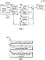
- FIG. 2 shows a schematic representation of a control system 200 for a FBW aircraft in accordance with one aspect of the present invention.
- the control system 200 includes a pilot control interface 202 that includes various control devices accessible to the pilot.
- the pilot control interface 202 includes a a cyclic inceptor.
- the pilot control interface 202 also includes pedals, collective inceptor, etc.
- the control system 200 is provided to fly the aircraft using a model following control mode.
- a positon of the cyclic inceptor provides a control input to a command model 206.
- the command model 206 determines a commanded response of the aircraft (e.g., selected attitude, airspeed, vertical velocity, angular rates, altitude, etc.) from the control input.
- the command response is then fed into an inverse model 208 of the aircraft.
- the inverse model 208 of the aircraft determines a desired state of the aircraft 10 (i.e., a configuration of one or more flight surfaces of the aircraft 10) that will obtain the commanded response.
- the commanded response from the command model 206 is also provided to a rate feedback model 210 and an attitude feedback model 212.
- the rate feedback model 210 and attitude feedback model 212 provide information on a current state of the aircraft, e.g., its current attitude, airspeed, vertical velocity, angular rates, altitude, etc.
- a difference or error is determined between the desired state of the aircraft from the inverse model 208 and the current state of the aircraft (from the rate feedback model 210 and attitude feedback model 212). These differences, or errors, are synthesized to an aircraft control command 214.
- the aircraft control command 214 uses the determined errors to determine a change to one or more flight control surfaces of the aircraft that obtains the pilot's commanded response and then moves the flight control surfaces of the aircraft appropriately, thereby obtaining the desired state of the aircraft.
- a transient behavior occurs in the cyclic and other control devices.
- a trim follow up function is applied during the transition from proportional ground control operation mode to model following controls mode.
- the trim follow up function feeds input from the control devices to integrators to slowly translate the flight control position towards the controller position.
- the controller eventually returns to detent, while the flight control surface remains in the new trimmed state.
- the pilot can depress button 204 to implement the trim follow up function.
- the button 204 is shown located on the cyclic 202, but can be located at any suitable location. When the button 204 is depressed, the command signal input from the control interface 202 is sent to both the command model 206 and a mode logic module 216, which implements the trim follow up function.
- the mode logic module 216 sends a signal to allow the trim follow up function to the trim integrator 218.
- the trim follow up function and command signals from the command model 206 are sent to a trim integrator 218, which Fades in the trim follow up function.
- the trim integrator 218 then provides a trim integration signal to the aircraft control command 220,
- the aircraft control command 220 also receives the desired state of the aircraft from the inverse model 208, rate feedback from the rate feedback model 210, and attitude feedback from the attitude feedback model 212.
- FIG. 3 shows a flowchart 300 illustrating a method of transitioning between flight control modes according to an embodiment of the present invention.
- the pilot flies the aircraft in proportional ground control mode.
- the pilot implements the trim follow up function by depressing button 204 while in proportional ground control mode.
- the pilot switches to model following control mode, so that the trim follow up function is integrated into the control system during the transition.
- depressing button 204 both activates the trim follow up function and begins the transition into the model following controls mode.
Applications Claiming Priority (1)
| Application Number | Priority Date | Filing Date | Title |
|---|---|---|---|
| US201662278220P | 2016-01-13 | 2016-01-13 |
Publications (2)
| Publication Number | Publication Date |
|---|---|
| EP3193230A1 true EP3193230A1 (fr) | 2017-07-19 |
| EP3193230B1 EP3193230B1 (fr) | 2020-01-01 |
Family
ID=57794177
Family Applications (1)
| Application Number | Title | Priority Date | Filing Date |
|---|---|---|---|
| EP17151148.8A Active EP3193230B1 (fr) | 2016-01-13 | 2017-01-12 | Compensateur activé par le pilote sur aéronef à commande électrique |
Country Status (2)
| Country | Link |
|---|---|
| US (1) | US10618635B2 (fr) |
| EP (1) | EP3193230B1 (fr) |
Citations (3)
| Publication number | Priority date | Publication date | Assignee | Title |
|---|---|---|---|---|
| US5446666A (en) * | 1994-05-17 | 1995-08-29 | The Boeing Company | Ground state-fly state transition control for unique-trim aircraft flight control system |
| WO2008108787A2 (fr) * | 2006-06-02 | 2008-09-12 | Sikorsky Aircraft Corporation | Système d'atterrissage a neutralisation de la fonction de contact avec le sol pour aéronef à voilure tournante |
| EP2672357A1 (fr) * | 2012-06-05 | 2013-12-11 | Bell Helicopter Textron Inc. | Système de gestion de protection de décollage/atterrissage |
Family Cites Families (6)
| Publication number | Priority date | Publication date | Assignee | Title |
|---|---|---|---|---|
| US4603388A (en) * | 1983-02-16 | 1986-07-29 | Sperry Corporation | VTOL altitude hold system with automatic ground effect compensation |
| US5001646A (en) * | 1988-12-19 | 1991-03-19 | Mcdonnell Douglas Corporation | Automated helicopter flight control system |
| US5493497A (en) * | 1992-06-03 | 1996-02-20 | The Boeing Company | Multiaxis redundant fly-by-wire primary flight control system |
| US5596499A (en) * | 1995-02-21 | 1997-01-21 | The Boeing Company | Control law mode switching between rate command and attitude command control systems |
| US8271151B2 (en) * | 2008-03-31 | 2012-09-18 | Sikorsky Aircraft Corporation | Flight control system for rotary wing aircraft |
| EP2261116B1 (fr) | 2009-06-09 | 2019-05-22 | Sikorsky Aircraft Corporation | Système de compensation automatique pour avion à commandes électriques avec contrôleurs de compensation uniques |
-
2017
- 2017-01-12 US US15/404,804 patent/US10618635B2/en active Active
- 2017-01-12 EP EP17151148.8A patent/EP3193230B1/fr active Active
Patent Citations (3)
| Publication number | Priority date | Publication date | Assignee | Title |
|---|---|---|---|---|
| US5446666A (en) * | 1994-05-17 | 1995-08-29 | The Boeing Company | Ground state-fly state transition control for unique-trim aircraft flight control system |
| WO2008108787A2 (fr) * | 2006-06-02 | 2008-09-12 | Sikorsky Aircraft Corporation | Système d'atterrissage a neutralisation de la fonction de contact avec le sol pour aéronef à voilure tournante |
| EP2672357A1 (fr) * | 2012-06-05 | 2013-12-11 | Bell Helicopter Textron Inc. | Système de gestion de protection de décollage/atterrissage |
Also Published As
| Publication number | Publication date |
|---|---|
| EP3193230B1 (fr) | 2020-01-01 |
| US10618635B2 (en) | 2020-04-14 |
| US20170197705A1 (en) | 2017-07-13 |
Similar Documents
| Publication | Publication Date | Title |
|---|---|---|
| US9851723B2 (en) | Method and apparatus for flight control of tiltrotor aircraft | |
| US7759894B2 (en) | Cogless motor driven active user interface haptic feedback system | |
| US8240617B2 (en) | Variable damping of haptic feedback for a flight-attitude changing linkage of an aircraft | |
| US9727059B2 (en) | Independent speed and attitude control for a rotary wing aircraft | |
| US8052094B2 (en) | Fast hybrid helicopter with long range with longitudinal trim control | |
| US7658349B2 (en) | Pilot flight control stick haptic feedback system and method | |
| US8181901B2 (en) | Fast hybrid helicopter with long range and proportional drive to the rotor and the propeller | |
| US20100219286A1 (en) | Fast hybrid helicopter with long range and an optimized lift rotor | |
| US20070235594A1 (en) | Pilot flight control stick feedback system | |
| EP3208190B1 (fr) | Système de commande de moment de rotor pour aéronef à voilure tournante | |
| EP3126231B1 (fr) | Commande de réduction de charges de gouverne de profondeur pour un aéronef à voilure tournante | |
| US20090302171A1 (en) | Rate limited active pilot inceptor system and method | |
| EP3326911B1 (fr) | Contrôle de la vitesse de rotor au moyen d'une commande de vitesse de rotor aval | |
| US10562609B2 (en) | High trim demand relief | |
| US10618635B2 (en) | Pilot activated trim for fly-by-wire aircraft | |
| US10359785B2 (en) | Touchdown orientation control system for a rotary wing aircraft and method | |
| US10641184B2 (en) | Dynamic flight command cross-feed for rotor speed droop reduction | |
| US11001376B2 (en) | Precision pointing mode of an aircraft | |
| US20240132202A1 (en) | Mode-dependent tactile feedback profiles for an inceptor | |
| US20230101964A1 (en) | Method for hovering an aircraft with respect to an axis with a controllable pitch angle |
Legal Events
| Date | Code | Title | Description |
|---|---|---|---|
| PUAI | Public reference made under article 153(3) epc to a published international application that has entered the european phase |
Free format text: ORIGINAL CODE: 0009012 |
|
| STAA | Information on the status of an ep patent application or granted ep patent |
Free format text: STATUS: THE APPLICATION HAS BEEN PUBLISHED |
|
| AK | Designated contracting states |
Kind code of ref document: A1 Designated state(s): AL AT BE BG CH CY CZ DE DK EE ES FI FR GB GR HR HU IE IS IT LI LT LU LV MC MK MT NL NO PL PT RO RS SE SI SK SM TR |
|
| AX | Request for extension of the european patent |
Extension state: BA ME |
|
| STAA | Information on the status of an ep patent application or granted ep patent |
Free format text: STATUS: REQUEST FOR EXAMINATION WAS MADE |
|
| 17P | Request for examination filed |
Effective date: 20180118 |
|
| RBV | Designated contracting states (corrected) |
Designated state(s): AL AT BE BG CH CY CZ DE DK EE ES FI FR GB GR HR HU IE IS IT LI LT LU LV MC MK MT NL NO PL PT RO RS SE SI SK SM TR |
|
| STAA | Information on the status of an ep patent application or granted ep patent |
Free format text: STATUS: EXAMINATION IS IN PROGRESS |
|
| 17Q | First examination report despatched |
Effective date: 20181026 |
|
| GRAP | Despatch of communication of intention to grant a patent |
Free format text: ORIGINAL CODE: EPIDOSNIGR1 |
|
| STAA | Information on the status of an ep patent application or granted ep patent |
Free format text: STATUS: GRANT OF PATENT IS INTENDED |
|
| INTG | Intention to grant announced |
Effective date: 20190723 |
|
| GRAS | Grant fee paid |
Free format text: ORIGINAL CODE: EPIDOSNIGR3 |
|
| GRAA | (expected) grant |
Free format text: ORIGINAL CODE: 0009210 |
|
| STAA | Information on the status of an ep patent application or granted ep patent |
Free format text: STATUS: THE PATENT HAS BEEN GRANTED |
|
| AK | Designated contracting states |
Kind code of ref document: B1 Designated state(s): AL AT BE BG CH CY CZ DE DK EE ES FI FR GB GR HR HU IE IS IT LI LT LU LV MC MK MT NL NO PL PT RO RS SE SI SK SM TR |
|
| REG | Reference to a national code |
Ref country code: GB Ref legal event code: FG4D |
|
| REG | Reference to a national code |
Ref country code: CH Ref legal event code: EP Ref country code: AT Ref legal event code: REF Ref document number: 1220579 Country of ref document: AT Kind code of ref document: T Effective date: 20200115 |
|
| REG | Reference to a national code |
Ref country code: IE Ref legal event code: FG4D |
|
| REG | Reference to a national code |
Ref country code: DE Ref legal event code: R096 Ref document number: 602017010222 Country of ref document: DE |
|
| REG | Reference to a national code |
Ref country code: NL Ref legal event code: MP Effective date: 20200101 |
|
| REG | Reference to a national code |
Ref country code: LT Ref legal event code: MG4D |
|
| PG25 | Lapsed in a contracting state [announced via postgrant information from national office to epo] |
Ref country code: NO Free format text: LAPSE BECAUSE OF FAILURE TO SUBMIT A TRANSLATION OF THE DESCRIPTION OR TO PAY THE FEE WITHIN THE PRESCRIBED TIME-LIMIT Effective date: 20200401 Ref country code: LT Free format text: LAPSE BECAUSE OF FAILURE TO SUBMIT A TRANSLATION OF THE DESCRIPTION OR TO PAY THE FEE WITHIN THE PRESCRIBED TIME-LIMIT Effective date: 20200101 Ref country code: PT Free format text: LAPSE BECAUSE OF FAILURE TO SUBMIT A TRANSLATION OF THE DESCRIPTION OR TO PAY THE FEE WITHIN THE PRESCRIBED TIME-LIMIT Effective date: 20200527 Ref country code: FI Free format text: LAPSE BECAUSE OF FAILURE TO SUBMIT A TRANSLATION OF THE DESCRIPTION OR TO PAY THE FEE WITHIN THE PRESCRIBED TIME-LIMIT Effective date: 20200101 Ref country code: CZ Free format text: LAPSE BECAUSE OF FAILURE TO SUBMIT A TRANSLATION OF THE DESCRIPTION OR TO PAY THE FEE WITHIN THE PRESCRIBED TIME-LIMIT Effective date: 20200101 Ref country code: RS Free format text: LAPSE BECAUSE OF FAILURE TO SUBMIT A TRANSLATION OF THE DESCRIPTION OR TO PAY THE FEE WITHIN THE PRESCRIBED TIME-LIMIT Effective date: 20200101 Ref country code: NL Free format text: LAPSE BECAUSE OF FAILURE TO SUBMIT A TRANSLATION OF THE DESCRIPTION OR TO PAY THE FEE WITHIN THE PRESCRIBED TIME-LIMIT Effective date: 20200101 |
|
| PG25 | Lapsed in a contracting state [announced via postgrant information from national office to epo] |
Ref country code: BG Free format text: LAPSE BECAUSE OF FAILURE TO SUBMIT A TRANSLATION OF THE DESCRIPTION OR TO PAY THE FEE WITHIN THE PRESCRIBED TIME-LIMIT Effective date: 20200401 Ref country code: SE Free format text: LAPSE BECAUSE OF FAILURE TO SUBMIT A TRANSLATION OF THE DESCRIPTION OR TO PAY THE FEE WITHIN THE PRESCRIBED TIME-LIMIT Effective date: 20200101 Ref country code: LV Free format text: LAPSE BECAUSE OF FAILURE TO SUBMIT A TRANSLATION OF THE DESCRIPTION OR TO PAY THE FEE WITHIN THE PRESCRIBED TIME-LIMIT Effective date: 20200101 Ref country code: IS Free format text: LAPSE BECAUSE OF FAILURE TO SUBMIT A TRANSLATION OF THE DESCRIPTION OR TO PAY THE FEE WITHIN THE PRESCRIBED TIME-LIMIT Effective date: 20200501 Ref country code: HR Free format text: LAPSE BECAUSE OF FAILURE TO SUBMIT A TRANSLATION OF THE DESCRIPTION OR TO PAY THE FEE WITHIN THE PRESCRIBED TIME-LIMIT Effective date: 20200101 Ref country code: GR Free format text: LAPSE BECAUSE OF FAILURE TO SUBMIT A TRANSLATION OF THE DESCRIPTION OR TO PAY THE FEE WITHIN THE PRESCRIBED TIME-LIMIT Effective date: 20200402 |
|
| REG | Reference to a national code |
Ref country code: CH Ref legal event code: PL |
|
| REG | Reference to a national code |
Ref country code: DE Ref legal event code: R097 Ref document number: 602017010222 Country of ref document: DE |
|
| REG | Reference to a national code |
Ref country code: BE Ref legal event code: MM Effective date: 20200131 |
|
| PG25 | Lapsed in a contracting state [announced via postgrant information from national office to epo] |
Ref country code: MC Free format text: LAPSE BECAUSE OF FAILURE TO SUBMIT A TRANSLATION OF THE DESCRIPTION OR TO PAY THE FEE WITHIN THE PRESCRIBED TIME-LIMIT Effective date: 20200101 Ref country code: RO Free format text: LAPSE BECAUSE OF FAILURE TO SUBMIT A TRANSLATION OF THE DESCRIPTION OR TO PAY THE FEE WITHIN THE PRESCRIBED TIME-LIMIT Effective date: 20200101 Ref country code: LU Free format text: LAPSE BECAUSE OF NON-PAYMENT OF DUE FEES Effective date: 20200112 Ref country code: ES Free format text: LAPSE BECAUSE OF FAILURE TO SUBMIT A TRANSLATION OF THE DESCRIPTION OR TO PAY THE FEE WITHIN THE PRESCRIBED TIME-LIMIT Effective date: 20200101 Ref country code: EE Free format text: LAPSE BECAUSE OF FAILURE TO SUBMIT A TRANSLATION OF THE DESCRIPTION OR TO PAY THE FEE WITHIN THE PRESCRIBED TIME-LIMIT Effective date: 20200101 Ref country code: SM Free format text: LAPSE BECAUSE OF FAILURE TO SUBMIT A TRANSLATION OF THE DESCRIPTION OR TO PAY THE FEE WITHIN THE PRESCRIBED TIME-LIMIT Effective date: 20200101 Ref country code: SK Free format text: LAPSE BECAUSE OF FAILURE TO SUBMIT A TRANSLATION OF THE DESCRIPTION OR TO PAY THE FEE WITHIN THE PRESCRIBED TIME-LIMIT Effective date: 20200101 Ref country code: DK Free format text: LAPSE BECAUSE OF FAILURE TO SUBMIT A TRANSLATION OF THE DESCRIPTION OR TO PAY THE FEE WITHIN THE PRESCRIBED TIME-LIMIT Effective date: 20200101 |
|
| PLBE | No opposition filed within time limit |
Free format text: ORIGINAL CODE: 0009261 |
|
| STAA | Information on the status of an ep patent application or granted ep patent |
Free format text: STATUS: NO OPPOSITION FILED WITHIN TIME LIMIT |
|
| REG | Reference to a national code |
Ref country code: AT Ref legal event code: MK05 Ref document number: 1220579 Country of ref document: AT Kind code of ref document: T Effective date: 20200101 |
|
| PG25 | Lapsed in a contracting state [announced via postgrant information from national office to epo] |
Ref country code: CH Free format text: LAPSE BECAUSE OF NON-PAYMENT OF DUE FEES Effective date: 20200131 Ref country code: LI Free format text: LAPSE BECAUSE OF NON-PAYMENT OF DUE FEES Effective date: 20200131 Ref country code: BE Free format text: LAPSE BECAUSE OF NON-PAYMENT OF DUE FEES Effective date: 20200131 |
|
| 26N | No opposition filed |
Effective date: 20201002 |
|
| PG25 | Lapsed in a contracting state [announced via postgrant information from national office to epo] |
Ref country code: IT Free format text: LAPSE BECAUSE OF FAILURE TO SUBMIT A TRANSLATION OF THE DESCRIPTION OR TO PAY THE FEE WITHIN THE PRESCRIBED TIME-LIMIT Effective date: 20200101 Ref country code: AT Free format text: LAPSE BECAUSE OF FAILURE TO SUBMIT A TRANSLATION OF THE DESCRIPTION OR TO PAY THE FEE WITHIN THE PRESCRIBED TIME-LIMIT Effective date: 20200101 Ref country code: IE Free format text: LAPSE BECAUSE OF NON-PAYMENT OF DUE FEES Effective date: 20200112 |
|
| PG25 | Lapsed in a contracting state [announced via postgrant information from national office to epo] |
Ref country code: SI Free format text: LAPSE BECAUSE OF FAILURE TO SUBMIT A TRANSLATION OF THE DESCRIPTION OR TO PAY THE FEE WITHIN THE PRESCRIBED TIME-LIMIT Effective date: 20200101 Ref country code: PL Free format text: LAPSE BECAUSE OF FAILURE TO SUBMIT A TRANSLATION OF THE DESCRIPTION OR TO PAY THE FEE WITHIN THE PRESCRIBED TIME-LIMIT Effective date: 20200101 |
|
| PG25 | Lapsed in a contracting state [announced via postgrant information from national office to epo] |
Ref country code: TR Free format text: LAPSE BECAUSE OF FAILURE TO SUBMIT A TRANSLATION OF THE DESCRIPTION OR TO PAY THE FEE WITHIN THE PRESCRIBED TIME-LIMIT Effective date: 20200101 Ref country code: MT Free format text: LAPSE BECAUSE OF FAILURE TO SUBMIT A TRANSLATION OF THE DESCRIPTION OR TO PAY THE FEE WITHIN THE PRESCRIBED TIME-LIMIT Effective date: 20200101 Ref country code: CY Free format text: LAPSE BECAUSE OF FAILURE TO SUBMIT A TRANSLATION OF THE DESCRIPTION OR TO PAY THE FEE WITHIN THE PRESCRIBED TIME-LIMIT Effective date: 20200101 |
|
| PG25 | Lapsed in a contracting state [announced via postgrant information from national office to epo] |
Ref country code: MK Free format text: LAPSE BECAUSE OF FAILURE TO SUBMIT A TRANSLATION OF THE DESCRIPTION OR TO PAY THE FEE WITHIN THE PRESCRIBED TIME-LIMIT Effective date: 20200101 Ref country code: AL Free format text: LAPSE BECAUSE OF FAILURE TO SUBMIT A TRANSLATION OF THE DESCRIPTION OR TO PAY THE FEE WITHIN THE PRESCRIBED TIME-LIMIT Effective date: 20200101 |
|
| PGFP | Annual fee paid to national office [announced via postgrant information from national office to epo] |
Ref country code: FR Payment date: 20230125 Year of fee payment: 7 |
|
| PGFP | Annual fee paid to national office [announced via postgrant information from national office to epo] |
Ref country code: GB Payment date: 20230127 Year of fee payment: 7 Ref country code: DE Payment date: 20230127 Year of fee payment: 7 |
|
| P01 | Opt-out of the competence of the unified patent court (upc) registered |
Effective date: 20230517 |
|
| REG | Reference to a national code |
Ref country code: DE Ref legal event code: R079 Ref document number: 602017010222 Country of ref document: DE Free format text: PREVIOUS MAIN CLASS: G05D0001060000 Ipc: G05D0001485000 |