EP3193200A1 - Lens barrel and camera - Google Patents
Lens barrel and camera Download PDFInfo
- Publication number
- EP3193200A1 EP3193200A1 EP15839442.9A EP15839442A EP3193200A1 EP 3193200 A1 EP3193200 A1 EP 3193200A1 EP 15839442 A EP15839442 A EP 15839442A EP 3193200 A1 EP3193200 A1 EP 3193200A1
- Authority
- EP
- European Patent Office
- Prior art keywords
- diaphragm
- diaphragm ring
- lens barrel
- fitting
- facing
- Prior art date
- Legal status (The legal status is an assumption and is not a legal conclusion. Google has not performed a legal analysis and makes no representation as to the accuracy of the status listed.)
- Granted
Links
Images





Classifications
-
- G—PHYSICS
- G03—PHOTOGRAPHY; CINEMATOGRAPHY; ANALOGOUS TECHNIQUES USING WAVES OTHER THAN OPTICAL WAVES; ELECTROGRAPHY; HOLOGRAPHY
- G03B—APPARATUS OR ARRANGEMENTS FOR TAKING PHOTOGRAPHS OR FOR PROJECTING OR VIEWING THEM; APPARATUS OR ARRANGEMENTS EMPLOYING ANALOGOUS TECHNIQUES USING WAVES OTHER THAN OPTICAL WAVES; ACCESSORIES THEREFOR
- G03B9/00—Exposure-making shutters; Diaphragms
- G03B9/02—Diaphragms
- G03B9/06—Two or more co-operating pivoted blades, e.g. iris type
-
- G—PHYSICS
- G02—OPTICS
- G02B—OPTICAL ELEMENTS, SYSTEMS OR APPARATUS
- G02B5/00—Optical elements other than lenses
- G02B5/005—Diaphragms
-
- G—PHYSICS
- G02—OPTICS
- G02B—OPTICAL ELEMENTS, SYSTEMS OR APPARATUS
- G02B7/00—Mountings, adjusting means, or light-tight connections, for optical elements
- G02B7/02—Mountings, adjusting means, or light-tight connections, for optical elements for lenses
Definitions
- This invention relates to a lens barrel with diaphragm mechanism that has a diaphragm which aperture diameter can be changed, a fixed portion that stores the diaphragm, and a diaphragm ring that is rotatably attached to the fixed portion so as to adjust the aperture diameter of the diaphragm, and a camera with the lens barrel.
- a diaphragm value is changed (adjusted) in a camera body.
- a lens barrel is provided with a diaphragm ring, and the diaphragm value is changed by turning the diaphragm ring (for instance, see Patent related document 1).
- Fig.7 is a plan view that shows an instance of a conventional structure of a lens barrel with diaphragm adjustment mechanism, and a reference number 100 in the figure denotes a lens barrel, a reference number 104 denotes a diaphragm ring being free to be rotated, and a reference number 105 denotes a focus ring.
- a diaphragm ring 104 is provided with a click mechanism (not shown) that is configured to fix the diaphragm ring 104 at a predetermined diaphragm value, F-value, such as F1.4, F2, F2.8 ... so as to restrict its free rotation.
- the diaphragm value When taking a still image with such a camera, the diaphragm value is set in advance, taking brightness of a subject into consideration.
- the change of the diaphragm value is desired without fixing during taking it. For instance, in a case where a motion picture is obtained in a moving helicopter or on a car, or a motion picture is obtained, putting the cameral on a radio control helicopter, brightness of a subject may be widely changed, and a diaphragm value may be needed to be changed in order, depending on the brightness of a subject.
- the above-mentioned click mechanism may obstruct a smooth rotation of the diaphragm ring 104, and a microphone of the camera may catch click sounds.
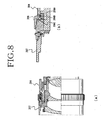
- Fig. 8 (a) is a cross sectional view that shows another instance of the lens barrel with diaphragm adjustment mechanism having a conventional configuration
- Fig.8(b) is its enlarged sectional view.
- a reference number 204 in the figure denotes a diaphragm ring
- a reference number 206 is a click mechanism
- a reference number 206A denotes a spring that is a component of the click mechanism 206
- a reference number 206B denotes a click ball that is energized through the spring 206A.
- a reference number 206C denotes an engaged portion with which the click ball 206B is able to be engaged
- a reference number 207 denotes an annular member which end surface has two or more engaged portions 206C.
- Such a annular member 207 is configured to be freely rotated, such that a contact between the click ball 206B and the engaged portion 206C is released when the annular member 207 is 180° rotated, and the click mechanism stops.
- An object of the invention is to provide the lens barrel for solving the above-mentioned problem and the cameral with such a lens barrel.
- a first aspect of the invention as exemplarily shown in Figs.1 through 4 and 9 is a lens barrel (1, 301) that has a diaphragm (2, 302) which aperture diameter can be changed, a fixed portion (3, 303) that stores the diaphragm (2, 302), a diaphragm ring (4, 304) that is rotatably attached to the fixed portion (3, 303) so as to adjust an aperture diameter of the diaphragm (2, 302); comprising:
- the second aspect of the invention is the lens barrel, provided that an outside of the lens barrel (1, 301) in a radius direction (Rout) is “lens barrel outside direction” and an inside of the lens barrel (1, 301) in a radius direction (Rin) is “lens barrel inside direction", further comprising first and second spring members (53A, 53B or 353A, 353B) attached on a side of the diaphragm (2, 302) so as to energize the first and second projections (50A, 50B or 350A, 350B) in the lens barrel outside direction (Rout); and
- the third aspect of the invention is the lens barrel, wherein the push button (521, 3521) is located so as to be inserted in a through hole (not shown) that is formed at the diaphragm ring (4, 304).
- the fourth aspect of the invention as exemplarily shown in Figs.6(a), (b) is the lens barrel wherein an indicator (Q) is indicated at a position adjacent to the diaphragm ring (4, 304) on the fixed portion (3, 303), two or more F-values (4A) are indicated in a range of a circumferential direction of the diaphragm ring (4, 304), facing to the indication (Q) when the diaphragm ring (4, 304) is rotated, fitting the first projection (50A, 350A) into the fitting member (51, 351), and two or more T-values (4B) are indicated in the range of the circumferential direction of the diaphragm ring (4, 304), facing to the indication (Q) when the diaphragm ring (4, 304) is rotated, fitting the second projection (50B, 350B) into the fitting member (51, 351), and the diaphragm (2, 302) is configured to have an opening in a size to realize the F-values
- the fifth aspect of the invention is a camera with the lens barrel (1, 301).
- the push button is located so as to project from the outer peripheral surface of the diaphragm ring to the lens barrel outside direction, so that such a button can be pushed into, grasping the diaphragm ring and the operation is simple.
- a lens barrel according to the invention is exemplarily shown in Figs.1 to 4 , 9 and 10 with reference numbers 1, 301, and has an diaphragm 2, 302 which aperture diameter can be changed, a fixed portion 3, 303 that stores the diaphragm 2, 302, and a diaphragm ring 4, 304 that is attached to the fixed portion 3, 303 so as to be free to be rotated and is configured to adjust the aperture diameter of the diaphragm 2, 302.
- the diaphragm 2, 302 is an iris diaphragm and is comprised of a plurality of diaphragm blades 20 having cam shafts 20a, 20b, and an annular operation member (see a reference number 21 of Figs.3 and 4 and a reference number 321 of Figs.9 and 10 ) having a plurality of cam holes (see a reference number 21a of Figs. 3 and 4 and a reference number 321 of Fig. 10 ) into which the cam shafts are respectively inserted, as exemplarily shown in Fig.5 .
- the fixed portion 3, 303 exemplarily shown in the figures is configured by connecting a plurality of cylindrical members 30 31 or a plurality of cylindrical members 330, 331 through screws, but may be integrally formed.
- the lens barrel 1, 301 has a connecting portion 5, 305 that connects the diaphragm 2, 302 and the diaphragm ring 4, 304 so as to contact with each other and leave from each other, and the connecting portion 5, 305 is comprised of
- peripheral directional positions of the fitting member 51 in the diaphragm ring 4 are different in Figs.1 and 2 and Figs.3 and 4 .
- the first and second projections 50A, 50B are configured to be energized in the lens barrel outside direction in Fig.1 , 2 and 9 .
- Such a configuration is not fixed, but the projections 50A, 50B may be energized in another direction, such as an optical axis direction x as long as both are energized on the diaphragm ring 4, 304 side, and the position of the fitting member 51, 351 may be properly changed to the position excluding one of the inner peripheral surface of the diaphragm ring 4, 304 (the position where the first and second projections 50A, 50B or the first and second projections 350A, 350B are energized).
- first projection 50A or the second projection 50B may be located at a portion where a member as shown with a reference number 61 in Figs.1 and 2(b) (details are mentioned later) is located and the other portion shifted from such a portion in a peripheral direction, such as the portion 180° away therefrom, and first and second spring members (detailedly mentioned hereinafter) are located at a portion where a spring member as shown with a reference number 60 is located and the other portion shifted from such a portion in the peripheral direction, such as the portion 180° away therefrom, so that these projections 50A, 50B can be energized in the optical axis direction, such as a direction opposite to the x direction.
- the fitting member 51 may be formed at the portion where the locked member as shown with the reference number 62 (detailedly mentioned hereinafter) is located.
- the link releaser 52, 352 is comprised of an actuator 520, 3520 that is located at a position where the first and second projections 50A, 50B (or the first and second projections 350A, 350B) in the fitting member 51, 351, are energized, and a push button 521, 3521 that is located so as to connect with the actuator 520, 3520 and to project from an outer peripheral face 4a, 304a of the diaphragm ring 4, 304 in the lens barrel outside direction Rout as detailedly shown in Fig.2(a) and Fig.9 , so that the fitting of the first or the second projection 50A, 50B (or the first or the second projection 350A, 350B) into the fitting member 51, 351 can be released in such a way that the push button 521, 3521 is pushed in the lens barrel inside direction Rin and
- a through hole is formed at the diaphragm ring 4, 304, and the push button 521, 3521 is located so as to be inserted in the through hole.
- a notch (not shown) or a clearance (that is, the clearance between the diaphragm ring and the fixed cylindrical member 31, 331) is formed at the diaphragm ring 4, 304 with no through hole and the push button 521, 3521 is located so as to project in the lens barrel outside direction Rout.
- the push button 521, 3521 may be continued being pushed during the rotation of the diaphragm ring 4, 304, or may not be continued being pushed when the engagement between the first or the second projection 50A, 50B (the first or the second projection 350A, 350B) and the fitting member 51, 351 is released.
- the push button 521, 3521 is located so as to project from the outer peripheral face 4a, 304a of the diaphragm ring 4, 304 in the lens barrel outside direction Rout, and for this reason, the push button 521, 3521 is pushed inside, holding the diaphragm ring 4, 304, and the operation is simple.
- both the fitting member 51, 351 and the link releaser 52, 352 may be located at two positions such that the first and second projections 50A, 50B (or the first and the second projections 350A, 350B) are fitted into the respective ones at the same time.
- both may be located at one position such that the second projection 50B, 350B is not engaged with the diaphragm ring 4, 304 when the first projection 50A, 350A is fitted into the fitting member 51, 351 and the first projection 50A, 350A is not engaged with the diaphragm ring 4, 304 when the second projection 50B, 350B is fitted into the fitting member 51, 351.
- the diaphragm ring 4, 304 is free to be rotated only by an operation of the link releaser 52, 352 located at one position, and the operation of the link release can be simple.
- the fitting member 51, 351 that is exemplarily shown in Fig. 2 (a) and Fig. 9 is in the shape of a groove that extends in the optional axis direction x of the lens barrel 1, 301, but is not limited to this shape and may be a concave portion that is not included in a concept of the groove.
- the fitting member 51, 351 may be not the groove nor the concave portion, but a convex portion, so that the concave portion or the groove is formed at the top of the projection 50A, 50B (or the projection 350A, 350B) so as to engage the fitting member and the projection with each other.
- first and second projections 50A, 50B are located 180° apart from each other along the peripheral direction C, but are not limited to such positions, and may be located at proper positions.
- the first and second projections 50A, 50B are energized in the lens barrel outside direction Rout through the first and second spring members 53A, 53B (or first and second spring members 353A, 353B) attached on the side of the diaphragm 2, 302.
- a member as shown with a reference number 54A, 54B in Figs.2(a), (b) and a member as shown with a reference number 354A, 354B in Fig.10 are ones for attaching the first and second spring members 53A, 53B to the diaphragm 2 (correctly speaking, the operation member 21).
- first and second spring members 53A, 53B (or the first and second spring members 353A, 353B) as exemplarily shown in Figs.1 through 4
- Figs. 9 and 10 are coil springs provided between the diaphragm 2, 302 and the first and second projections 50A, 50B (or the first and second projections 350A, 350B), but are not limited to ones, and may have another shapes.
- the lens barrel 1, 301 according to the invention has a click mechanism 6, 306 that is formed or located at the first facing portion P1 and the second facing portion P2, and is configured so as to give a feeling of a click to the rotation of the diaphragm ring 4, 304.
- the first and second facing portions P1, P2 as exemplarily shown in Fig.2(b) are end surfaces of the diaphragm ring 4 and the fixed portion 3 (that is, the end surfaces in the optical axis direction x and the portion adjacent to the end surface), but are not limited to such ones, and it is sufficient that the facing portions P1, P2 face each other.
- the portions P1 and P2 may be peripheral surfaces of the diaphragm ring 304 and the fixed portion 303 (that is, the outer peripheral surface and the portion adjacent thereto and the inner peripheral surface and the portion adjacent thereto) or another portions.
- the locking member 61 mentioned hereinafter may be located at the position where the first projection 50A or the second projection 50B is located in Fig. 1 and Fig. 2(b)
- the spring member for clicking 60 mentioned hereinafter may be located at the position where the first spring member 53A or the second spring member 53B is located
- the locked member 62 mentioned hereinafter may be located at the inner peripheral surface of the diaphragm ring 4 (that is, the position where the fitting member 51 is formed).
- the click mechanism 6, 306 has spring member for clicking 60, 360 attached to the first facing portion P1, a locking member 61, 361 that is energized on the side of the second facing portion P2 through the spring member for clicking 60, 360, and a locked member 62, 362 that is formed or located on the side of the second facing portion P2 so as to lock the locking member 61, 361.
- the second facing portion P2 has a locked surface P2a having two or more locked members 62 in a peripheral direction C, and a substantially flat surface P2b that has no locked member 62.
- the click mechanism is configured such that the locking member 61, 361 slides on the locked surface P2a when the diaphragm ring 4, 304 is rotated, fitting the first projection 50A, 350A into the fitting member 51, 351 and the locking member 61, 361 slides on the substantially flat surface P2b when the diaphragm ring 4, 304 is rotated, fitting the second projection 50B, 350B into the fitting member 51, 351.
- the spring member for clicking 60 is located on the side of the fixed portion 3 with the portion of the fixed portion 3 (the cylindrical member 31) facing to the diaphragm ring 4 as the first facing portion P1, and the locked member 62 is formed at the portion of the diaphragm ring 4 with the portion of the diaphragm ring 4 as the second facing portion P2.
- the spring member 60 for clicking 60 may be located at the portion of the diaphragm ring 4, and the locked member 62 may be formed at the portion of the fixed portion 3.
- the spring member for clicking 360 is located on the side of the diaphragm ring 304 with the portion of the diaphragm ring 304 as the first facing portion P1, and the locked member 362 is formed at the portion of a cylindrical portion 333 with a portion of the cylindrical portion 333 facing to the diaphragm ring 304 as the second facing portion P2.
- the spring member for clicking 360 may be located at the portion of the cylindrical portion 333, and the locked member 362 may be formed at the portion of the diaphragm ring 304.
- an indicator Q is indicated at a position adjacent to the diaphragm ring 4, 304 on the fixed portion 3, 303 (an annular member 32, 332), and two or more F-values 4A are indicated in a range of a circumferential direction of the diaphragm ring 4, 304, facing to the indication Q when the diaphragm ring 4, 304 is rotated, fitting the first projection 50A, 350A into the fitting member 51, 351, and two or more T-values (that is, effectiveness diaphragm values in consideration of the transmittance of the lens) are indicated in the range of the circumferential direction of the diaphragm ring 4, 304, facing to the indication Q when the diaphragm ring 4, 304 is rotated, fitting the second projection 50B, 350B into the fitting member 51, 351.
- the diaphragm 2, 302 (and the positions of the fitting member 51, 351 or the first and second projections 50A, 50B (or the first and second projections 350A, 350B)) is configured to have an opening in a size to realize the F- values 4A or the T-values 4B facing to the indication Q.
- the F-value is one that divides the focus distance of the lens by effective aperture diameter, and corresponds to brightness supposed that transmittance of the lens is 100%.
- the T-value is an index that shows substantial brightness adding the transmittance of an optical system (that is, the actual brightness to reach a sensor), and a relation between the T-value and F-value is expressed by the following expression.
- T value ( F value / transmittance % 1 / 2 ⁇ 10
- the diaphragm is adjusted with the F value when taking still images, and the diaphragm is adjusted with T-value when taking moving picture.
- both T-value and F-value are indicated on the diaphragm ring 4, 304, so that it is possible to properly adjust the diaphragm when both taking the still images and the moving pictures.
- the camera according to the invention as shown in claim 5 has the lens barrel 1, 301 having the above-mentioned configuration.
- the lens barrel 1, 301 is an exchangeable one, but the lens barrel that is impossible to be exchanged (that is, the lens barrel as a parts comprising the camera) is not excluded.
Landscapes
- Physics & Mathematics (AREA)
- General Physics & Mathematics (AREA)
- Optics & Photonics (AREA)
- Lens Barrels (AREA)
- Diaphragms For Cameras (AREA)
Abstract
Description
- This invention relates to a lens barrel with diaphragm mechanism that has a diaphragm which aperture diameter can be changed, a fixed portion that stores the diaphragm, and a diaphragm ring that is rotatably attached to the fixed portion so as to adjust the aperture diameter of the diaphragm, and a camera with the lens barrel.
- In late years, video cameras, single-lens reflex cameras and mirrorless cameras that are configured to take both motion pictures and still images (simply "the cameras" hereinafter) are spreading.
- Generally, in such a camera, a diaphragm value is changed (adjusted) in a camera body. But, in some cameras, a lens barrel is provided with a diaphragm ring, and the diaphragm value is changed by turning the diaphragm ring (for instance, see Patent related document 1).
-
Fig.7 is a plan view that shows an instance of a conventional structure of a lens barrel with diaphragm adjustment mechanism, and areference number 100 in the figure denotes a lens barrel, areference number 104 denotes a diaphragm ring being free to be rotated, and areference number 105 denotes a focus ring. Such adiaphragm ring 104 is provided with a click mechanism (not shown) that is configured to fix thediaphragm ring 104 at a predetermined diaphragm value, F-value, such as F1.4, F2, F2.8 ... so as to restrict its free rotation. - When taking a still image with such a camera, the diaphragm value is set in advance, taking brightness of a subject into consideration. In some cases, when taking a motion picture, the change of the diaphragm value is desired without fixing during taking it. For instance, in a case where a motion picture is obtained in a moving helicopter or on a car, or a motion picture is obtained, putting the cameral on a radio control helicopter, brightness of a subject may be widely changed, and a diaphragm value may be needed to be changed in order, depending on the brightness of a subject. In such a case, the above-mentioned click mechanism may obstruct a smooth rotation of the
diaphragm ring 104, and a microphone of the camera may catch click sounds. - Then, the lens barrel for solving such problems has been proposed (for instance, see Patent related document 2).
-
Fig. 8 (a) is a cross sectional view that shows another instance of the lens barrel with diaphragm adjustment mechanism having a conventional configuration, andFig.8(b) is its enlarged sectional view. Areference number 204 in the figure denotes a diaphragm ring, areference number 206 is a click mechanism, areference number 206A denotes a spring that is a component of theclick mechanism 206, and areference number 206B denotes a click ball that is energized through thespring 206A. And, a reference number 206C denotes an engaged portion with which theclick ball 206B is able to be engaged, and areference number 207 denotes an annular member which end surface has two or more engaged portions 206C. Such aannular member 207 is configured to be freely rotated, such that a contact between theclick ball 206B and the engaged portion 206C is released when theannular member 207 is 180° rotated, and the click mechanism stops. -
- Patent related document 1: Official gazette of
Japanese patent application publication No.2012-29152 - Patent related document 2: Official gazette of
Japanese patent No.5166597 - But, the configuration as shown in
Fig.8 has such a problem that it is necessary to rotate both theannular member 207 and thediaphragm ring 204 in order to stop the click mechanism and change the diaphragm value. Then, its operation is complex. - An object of the invention is to provide the lens barrel for solving the above-mentioned problem and the cameral with such a lens barrel.
- A first aspect of the invention as exemplarily shown in
Figs.1 through 4 and9 is a lens barrel (1, 301) that has a diaphragm (2, 302) which aperture diameter can be changed, a fixed portion (3, 303) that stores the diaphragm (2, 302), a diaphragm ring (4, 304) that is rotatably attached to the fixed portion (3, 303) so as to adjust an aperture diameter of the diaphragm (2, 302); comprising: - provided that a portion of the diaphragm ring (4, 304) facing to the fixed portion (3, 303) or a portion of the fixed portion (3, 303) facing to the diaphragm ring (4, 304) is "a first facing portion (see a reference number P1 of
Fig. 2 (b) andFig.9 )" and a portion of the fixed portion (3, 303) facing to the first facing portion (P1) or a portion of the diaphragm ring (4, 304) is "a second facing portion (see a reference number P2 of the same figure)",- first and second projections (50A, 50B or 350A, 350B) that are located at two positions along a peripheral direction (see arrow C of
Figs.3 and4 ) of the diaphragm (2, 302) so as to be energized on a side of the diaphragm ring (4, 304) from the diaphragm (2, 302); - a fitting member (51, 351) that is formed on a side of the diaphragm ring (4, 304) such that the first and second projections (50A, 50B or 350A, 350B) are alternatively fitted thereinto according to the rotation position of the diaphragm ring (4, 304) and the diaphragm ring (4, 304) is integrally rotated with the diaphragm (2, 302), and
- a link releaser (52, 352) that is configured that fitting of the first and second projections (50A, 50B or 350A, 350B) into the fitting member (51, 351) is released and the diaphragm ring (4, 304) rotates, being separated from the diaphragm (2, 302); and
- a click mechanism (6, 306) that is formed or located at the first facing portion (P1) and the second facing portion (P2) so as to give a feeling of a click to rotation of the diaphragm ring (4, 304);
- the click mechanism (6, 306) that has a spring member for clicking (60, 360) attached to the first facing portion (P1), a locking member (61, 361) that is energized on a side of the second facing portion (P2) through the spring member for clicking (60, 360), and a locked member (62, 362) that is formed or located on a side of the second facing portion (P2) so as to lock the locking member (61, 361);
- the second facing portion (P2) that has a locked surface (see a reference number P2a of
Fig. 3 ) having two or more locked members (62, 362) in a peripheral direction (C), and a substantially flat surface (see a reference number P2b ofFig.3 ) that has no locked member (62, 362);
- first and second projections (50A, 50B or 350A, 350B) that are located at two positions along a peripheral direction (see arrow C of
- whereby the locking member (61, 361) slides on the locked surface (P2a) when the diaphragm ring (4, 304) is rotated, fitting the first projection (50A, 350A) into the fitting member (51, 351) and the locking member (61, 361) slides on the substantially flat surface (P2b) when the diaphragm ring (4, 304) is rotated, fitting the second projection (50B, 350B) into the fitting member (51, 351).
- The second aspect of the invention is the lens barrel, provided that an outside of the lens barrel (1, 301) in a radius direction (Rout) is "lens barrel outside direction" and an inside of the lens barrel (1, 301) in a radius direction (Rin) is "lens barrel inside direction", further comprising first and second spring members (53A, 53B or 353A, 353B) attached on a side of the diaphragm (2, 302) so as to energize the first and second projections (50A, 50B or 350A, 350B) in the lens barrel outside direction (Rout); and
- the fitting member (51, 351) being formed at an inner peripheral face of the diaphragm ring (4, 304);
- the link releaser (52, 352) having an actuator (520, 3520) that is located at a position where the first and second projections (50A, 50B or 350A, 350B) in the fitting member (51, 351) are energized, and a push button (521, 3521) that is located so as to connect with the actuator (520, 3520) and to project from the outer peripheral face of the diaphragm ring (4, 304) in the lens barrel outside direction (Rout);
- whereby fitting of the first or the second projection (50A, 50B or 350A, 350B) into the fitting member (51, 351) can be released in such a way that the push button (521, 3521) is pushed in the lens barrel inside direction (Rin) and the actuator (520, 3520) thus pushes the first or the second projection (50A, 50B or 350A, 350B) in the lens barrel inside direction (Rin) from the fitting member (51, 351).
- The third aspect of the invention is the lens barrel, wherein the push button (521, 3521) is located so as to be inserted in a through hole (not shown) that is formed at the diaphragm ring (4, 304).
- The fourth aspect of the invention as exemplarily shown in
Figs.6(a), (b) is the lens barrel wherein an indicator (Q) is indicated at a position adjacent to the diaphragm ring (4, 304) on the fixed portion (3, 303), two or more F-values (4A) are indicated in a range of a circumferential direction of the diaphragm ring (4, 304), facing to the indication (Q) when the diaphragm ring (4, 304) is rotated, fitting the first projection (50A, 350A) into the fitting member (51, 351), and two or more T-values (4B) are indicated in the range of the circumferential direction of the diaphragm ring (4, 304), facing to the indication (Q) when the diaphragm ring (4, 304) is rotated, fitting the second projection (50B, 350B) into the fitting member (51, 351), and the diaphragm (2, 302) is configured to have an opening in a size to realize the F-values (4A) or the T-values (4B) facing to the indication (Q). - The fifth aspect of the invention is a camera with the lens barrel (1, 301).
- The number in parentheses shows the corresponding element in the drawings for the sake of convenience, accordingly, the descriptions are not restricted and bound by the descriptions on the drawings.
- According to the first, fourth and fifth aspects of the invention, it is only the diaphragm ring to rotate in order to stop the click mechanism and to change the diaphragm value, and its operation is simple.
- According to the second and third aspects of the invention, the push button is located so as to project from the outer peripheral surface of the diaphragm ring to the lens barrel outside direction, so that such a button can be pushed into, grasping the diaphragm ring and the operation is simple.
-
-
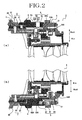
Fig.1 is a sectional view that shows an instance of a configuration of a lens barrel according to the invention. -
Fig.2(a), (b) are enlarged sectional views that show the lens barrel as shown inFig.1 . -
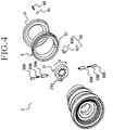
Fig.3 is a partially disassembled perspective view that shows an instance of the configuration of the lens barrel according to the invention. -
Fig.4 is a partially disassembled perspective view that shows an instance of the configuration of the lens barrel according to the invention. -
Fig.5 is a front view that shows an instance of the configuration of a diaphragm blade. -
Fig.6(a) is a plan view (the view that is seen from arrow G ofFig.1 ) that shows a F-value indication section, andFig. 6 (b) is a plan view (the view that is seen from arrow H ofFig.1 ) that shows a T-value indication section. -
Fig.7 is a plan view that shown an instance of a conventional configuration of the lens barrel with diaphragm adjustment function. -
Fig.8(a) is a partial sectional view that shows an another instance of the conventional configuration of the lens barrel with diaphragm adjustment function andFig. 8 (b) is its enlarged sectional view. -
Fig.9 is a sectional view that shows another instance of the configuration of the lens barrel according to the invention. -
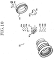
Fig.10 is a disassembled perspective view that shown the configuration of the lens barrel as shown inFig.9 . - Embodiments of the invention are mentioned, referring to appended drawings
Figs.1 to 6 , andFig.9 and10 . - A lens barrel according to the invention is exemplarily shown in
Figs.1 to 4 ,9 and10 withreference numbers diaphragm 2, 302 which aperture diameter can be changed, afixed portion diaphragm 2, 302, and adiaphragm ring portion diaphragm 2, 302. - Preferably, the
diaphragm 2, 302 is an iris diaphragm and is comprised of a plurality ofdiaphragm blades 20 havingcam shafts reference number 21 ofFigs.3 and4 and areference number 321 ofFigs.9 and10 ) having a plurality of cam holes (see areference number 21a ofFigs. 3 and4 and areference number 321 ofFig. 10 ) into which the cam shafts are respectively inserted, as exemplarily shown inFig.5 . Thefixed portion cylindrical members 30 31 or a plurality ofcylindrical members - Besides, the
lens barrel portion diaphragm 2, 302 and thediaphragm ring portion - ▪ first and
second projections second projections diaphragm 2, 302 (see arrow C ofFigs.3 ,4 and10 ) so as to be energized on a side of thediaphragm ring 4, 304 (preferably, on the side of thediaphragm ring diaphragm 2, 302), - ▪ a
fitting member diaphragm ring second projections second projections diaphragm ring diaphragm ring diaphragm 2, 302, and - ▪ a
link releaser second projections second projections fitting member 51, 351 (that is, the fitting of thefirst projection first projection fitting member second projection second projection fitting member 51, 351) is released and thediaphragm ring diaphragm 2, 302. - According to the invention, it is
only diaphragm ring - For convenience of the explanation, the peripheral directional positions of the
fitting member 51 in the diaphragm ring 4 (that is, a relative positional relation in the peripheral direction between thefitting member 51 and a lockedmember 62 that is mentioned hereinafter) are different inFigs.1 and2 andFigs.3 and4 . - Provided that an outside of the
lens barrel lens barrel second projections second projections Fig.1 ,2 and9 . Such a configuration is not fixed, but theprojections diaphragm ring fitting member diaphragm ring 4, 304 (the position where the first andsecond projections second projections first projection 50A or thesecond projection 50B may be located at a portion where a member as shown with areference number 61 inFigs.1 and2(b) (details are mentioned later) is located and the other portion shifted from such a portion in a peripheral direction, such as the portion 180° away therefrom, and first and second spring members (detailedly mentioned hereinafter) are located at a portion where a spring member as shown with areference number 60 is located and the other portion shifted from such a portion in the peripheral direction, such as the portion 180° away therefrom, so that theseprojections fitting member 51 may be formed at the portion where the locked member as shown with the reference number 62 (detailedly mentioned hereinafter) is located. - In a case where the first and
second projections second projections link releaser actuator second projections second projections fitting member push button actuator peripheral face 4a, 304a of thediaphragm ring Fig.2(a) andFig.9 , so that the fitting of the first or thesecond projection second projection fitting member push button actuator second projection second projection fitting member diaphragm ring push button cylindrical member 31, 331) is formed at thediaphragm ring push button push button diaphragm ring second projection second projection fitting member push button peripheral face 4a, 304a of thediaphragm ring push button diaphragm ring - On the other hand, both the
fitting member link releaser second projections second projections second projection diaphragm ring first projection fitting member first projection diaphragm ring second projection fitting member diaphragm ring link releaser - The
fitting member Fig. 2 (a) andFig. 9 is in the shape of a groove that extends in the optional axis direction x of thelens barrel fitting member projection projection Figs.1 and9 , the first andsecond projections second projections - On the other hand, preferably, the first and
second projections second projections second spring members second spring members diaphragm 2, 302. A member as shown with areference number Figs.2(a), (b) and a member as shown with areference number Fig.10 are ones for attaching the first andsecond spring members second spring members second spring members Figs.1 through 4 , andFigs. 9 and10 are coil springs provided between thediaphragm 2, 302 and the first andsecond projections second projections - Provided that the portion of the
diaphragm ring portion portion diaphragm ring Fig.2(b) andFig.9 ) and the portion of the fixedportion diaphragm ring lens barrel click mechanism diaphragm ring Fig.2(b) are end surfaces of thediaphragm ring 4 and the fixed portion 3 (that is, the end surfaces in the optical axis direction x and the portion adjacent to the end surface), but are not limited to such ones, and it is sufficient that the facing portions P1, P2 face each other. As exemplarily shown inFig. 9 , the portions P1 and P2 may be peripheral surfaces of thediaphragm ring 304 and the fixed portion 303 (that is, the outer peripheral surface and the portion adjacent thereto and the inner peripheral surface and the portion adjacent thereto) or another portions. For instance, the lockingmember 61 mentioned hereinafter may be located at the position where thefirst projection 50A or thesecond projection 50B is located inFig. 1 andFig. 2(b) , the spring member for clicking 60 mentioned hereinafter may be located at the position where thefirst spring member 53A or thesecond spring member 53B is located, and the lockedmember 62 mentioned hereinafter may be located at the inner peripheral surface of the diaphragm ring 4 (that is, the position where thefitting member 51 is formed). - As detailedly shown in
Fig. 2 (b) andFig. 9 , theclick mechanism member member member Fig.3 , the second facing portion P2 has a locked surface P2a having two or more lockedmembers 62 in a peripheral direction C, and a substantially flat surface P2b that has no lockedmember 62. As the result, the click mechanism is configured such that the lockingmember diaphragm ring first projection fitting member member diaphragm ring second projection fitting member Fig.2(b) , the spring member for clicking 60 is located on the side of the fixedportion 3 with the portion of the fixed portion 3 (the cylindrical member 31) facing to thediaphragm ring 4 as the first facing portion P1, and the lockedmember 62 is formed at the portion of thediaphragm ring 4 with the portion of thediaphragm ring 4 as the second facing portion P2. On the contrary, thespring member 60 for clicking 60 may be located at the portion of thediaphragm ring 4, and the lockedmember 62 may be formed at the portion of the fixedportion 3. In an instance as shown inFig.9 , the spring member for clicking 360 is located on the side of thediaphragm ring 304 with the portion of thediaphragm ring 304 as the first facing portion P1, and the lockedmember 362 is formed at the portion of acylindrical portion 333 with a portion of thecylindrical portion 333 facing to thediaphragm ring 304 as the second facing portion P2. On the contrary, the spring member for clicking 360 may be located at the portion of thecylindrical portion 333, and the lockedmember 362 may be formed at the portion of thediaphragm ring 304. - As exemplarily shown in
Fig.6(a) , preferably, an indicator Q is indicated at a position adjacent to thediaphragm ring portion 3, 303 (anannular member 32, 332), and two or more F-values 4A are indicated in a range of a circumferential direction of thediaphragm ring diaphragm ring first projection fitting member diaphragm ring diaphragm ring second projection fitting member diaphragm 2, 302 (and the positions of thefitting member second projections second projections values 4A or the T-values 4B facing to the indication Q. The F-value is one that divides the focus distance of the lens by effective aperture diameter, and corresponds to brightness supposed that transmittance of the lens is 100%. And, the T-value is an index that shows substantial brightness adding the transmittance of an optical system (that is, the actual brightness to reach a sensor), and a relation between the T-value and F-value is expressed by the following expression.
- Conventionally, the diaphragm is adjusted with the F value when taking still images, and the diaphragm is adjusted with T-value when taking moving picture. According to the invention, both T-value and F-value are indicated on the
diaphragm ring - On the other hand, the camera according to the invention as shown in
claim 5 has thelens barrel lens barrel -
- 1
- lens barrel
- 2
- diaphragm
- 3
- fixed portion
- 4
- diaphragm ring
- 4A
- F-value
- 4B
- T-value
- 6
- click mechanism
- 50A
- first projection
- 50B
- second projection
- 51
- fitting member
- 52
- link releaser
- 53A
- first spring member
- 53B
- second spring member
- 60
- spring member for clicking
- 61
- locking member
- 62
- locked member
- 301
- lens barrel
- 302
- diaphragm
- 303
- fixed portion
- 304
- diaphragm ring
- 306
- click mechanism
- 350A
- first projection
- 350B
- second projection
- 351
- fitting member
- 352
- link releaser
- 353A
- first spring member
- 353B
- second spring member
- 360
- spring member for clicking
- 361
- locking member
- 362
- locked member
- 520
- actuator
- 521
- push button
- 3520
- actuator
- 3521
- push button
- C
- peripheral direction
- P1
- first facing portion
- P2
- second facing portion
- P2a
- locked surface
- P2b
- substantially flat surface
- Q
- indication
- Rin
- lens barrel inside direction
- Rout
- lens barrel outside direction
Claims (5)
- A lens barrel that has a diaphragm which aperture diameter can be changed, a fixed portion that stores the diaphragm, a diaphragm ring that is rotatably attached to the fixed portion so as to adjust an aperture diameter of the diaphragm; comprising:provided that a portion of the diaphragm ring facing to the fixed portion or a portion of the fixed portion facing to the diaphragm ring is "a first facing portion" and a portion of the fixed portion facing to the first facing portion or a portion of the diaphragm ring is "a second facing portion",first and second projections that are located at two positions along a peripheral direction of the diaphragm so as to be energized on a side of the diaphragm ring from the diaphragm;a fitting member that is formed on a side of the diaphragm ring such that the first and second projections are alternatively fitted thereinto according to the rotation position of the diaphragm ring and the diaphragm ring is integrally rotated with the diaphragm, anda link releaser that is configured that fitting of the first and second projections into the fitting member is released and the diaphragm ring rotates, being separated from the diaphragm ; anda click mechanism that is formed or located at the first facing portion and the second facing portion so as to give a feeling of a click to rotation of the diaphragm ring;the click mechanism that has a spring member for clicking attached to the first facing portion, a locking member that is energized on a side of the second facing portion through the spring member for clicking, and a locked member that is formed or located on a side of the second facing portion so as to lock the locking member;the second facing portion that has a locked surface having two or more locked members in a peripheral direction, and a substantially flat surface that has no locked member;whereby the locking member slides on the locked surface when the diaphragm ring is rotated, fitting the first projection into the fitting member and the locking member slides on the substantially flat surface when the diaphragm ring is rotated, fitting the second projection into the fitting member.
- The lens barrel according to claim 1, provided that an outside of the lens barrel in a radius direction is "lens barrel outside direction" is and an inside of the lens barrel in a radius direction "lens barrel inside direction", further comprising first and second spring members attached on a side of the diaphragm so as to energize the first and second projections in the lens barrel outside direction; andthe fitting member being formed at an inner peripheral face of the diaphragm ring;the link releaser having an actuator that is located at a position where the first and second projections in the fitting member are energized, and a push button that is located so as to connect with the actuator and to project from the outer peripheral face of the diaphragm ring in the lens barrel outside direction;whereby fitting of the first or the second projection into the fitting member can be released in such a way that the push button is pushed in the lens barrel inside direction and the actuator thus pushes the first or the second projection in the lens barrel inside direction from the fitting member.
- The lens barrel according to claim 2, wherein the push button is located so as to be inserted in a through hole that is formed at the diaphragm ring.
- The lens barrel according to any one of claims 1 through 3, wherein an indicator is indicated at a position adjacent to the diaphragm ring on the fixed portion , two or more F-values are indicated in a range of a circumferential direction of the diaphragm ring, facing to the indication when the diaphragm ring is rotated, fitting the first projection into the fitting member, and two or more T-values are indicated in the range of the circumferential direction of the diaphragm ring, facing to the indication when the diaphragm ring is rotated, fitting the second projection into the fitting member, and the diaphragm is configured to have an opening in a size to realize the F-values or the T-values facing to the indication.
- A camera with the lens barrel mentioned in any one of claims 1 through 4.
Applications Claiming Priority (3)
| Application Number | Priority Date | Filing Date | Title |
|---|---|---|---|
| JP2014182445 | 2014-09-08 | ||
| JP2015021467 | 2015-02-05 | ||
| PCT/JP2015/075334 WO2016039294A1 (en) | 2014-09-08 | 2015-09-07 | Lens barrel and camera |
Publications (3)
| Publication Number | Publication Date |
|---|---|
| EP3193200A1 true EP3193200A1 (en) | 2017-07-19 |
| EP3193200A4 EP3193200A4 (en) | 2018-04-25 |
| EP3193200B1 EP3193200B1 (en) | 2019-07-17 |
Family
ID=55459042
Family Applications (1)
| Application Number | Title | Priority Date | Filing Date |
|---|---|---|---|
| EP15839442.9A Active EP3193200B1 (en) | 2014-09-08 | 2015-09-07 | Lens barrel and camera |
Country Status (5)
| Country | Link |
|---|---|
| US (1) | US10310358B2 (en) |
| EP (1) | EP3193200B1 (en) |
| JP (1) | JP6557666B2 (en) |
| CN (1) | CN106796336B (en) |
| WO (1) | WO2016039294A1 (en) |
Families Citing this family (5)
| Publication number | Priority date | Publication date | Assignee | Title |
|---|---|---|---|---|
| CN109143530B (en) * | 2017-06-16 | 2021-06-18 | 宁波舜宇光电信息有限公司 | Lens and camera module comprising same |
| WO2019035262A1 (en) * | 2017-08-14 | 2019-02-21 | 富士フイルム株式会社 | Lens unit and camera system |
| JP7195601B2 (en) * | 2019-02-08 | 2022-12-26 | 株式会社シグマ | lens barrel |
| WO2024058175A1 (en) * | 2022-09-12 | 2024-03-21 | 株式会社ニコン | Lens barrel and imaging device |
| CN116381889A (en) * | 2023-03-28 | 2023-07-04 | 武汉高明兰光电科技有限公司 | color camera lens |
Family Cites Families (6)
| Publication number | Priority date | Publication date | Assignee | Title |
|---|---|---|---|---|
| US3997264A (en) * | 1973-05-14 | 1976-12-14 | Minolta Camera Kabushiki Kaisha | Enlarging lens barrel |
| US4349265A (en) * | 1979-12-17 | 1982-09-14 | Canon Kabushiki Kaisha | Support structure for the aperture signal transmitting means in a camera lens assembly |
| CN103765274B (en) | 2011-08-31 | 2015-05-20 | 富士胶片株式会社 | Lens device and imaging device having said lens device |
| JP6088733B2 (en) * | 2011-11-29 | 2017-03-01 | オリンパス株式会社 | Imaging device |
| JP5166597B1 (en) * | 2011-12-27 | 2013-03-21 | 株式会社コシナ | Lens aperture device |
| JP2013137505A (en) * | 2012-10-01 | 2013-07-11 | Cosina Co Ltd | Lens diaphragm device |
-
2015
- 2015-09-07 JP JP2016547431A patent/JP6557666B2/en active Active
- 2015-09-07 US US15/504,419 patent/US10310358B2/en active Active
- 2015-09-07 CN CN201580046529.XA patent/CN106796336B/en active Active
- 2015-09-07 WO PCT/JP2015/075334 patent/WO2016039294A1/en not_active Ceased
- 2015-09-07 EP EP15839442.9A patent/EP3193200B1/en active Active
Also Published As
| Publication number | Publication date |
|---|---|
| US10310358B2 (en) | 2019-06-04 |
| US20180224712A1 (en) | 2018-08-09 |
| JPWO2016039294A1 (en) | 2017-06-15 |
| CN106796336A (en) | 2017-05-31 |
| JP6557666B2 (en) | 2019-08-07 |
| WO2016039294A1 (en) | 2016-03-17 |
| CN106796336B (en) | 2019-05-03 |
| EP3193200A4 (en) | 2018-04-25 |
| EP3193200B1 (en) | 2019-07-17 |
Similar Documents
| Publication | Publication Date | Title |
|---|---|---|
| EP3193200B1 (en) | Lens barrel and camera | |
| JP5330107B2 (en) | Aperture device | |
| US10634868B2 (en) | Lens barrel | |
| JP6624786B2 (en) | Aperture device, lens device having the same, and imaging device | |
| JP2012108260A (en) | Imaging apparatus and lens device | |
| CN110300925A (en) | Camera filter frame and camera filter unit | |
| JP6116261B2 (en) | Barrier device, lens barrel, and imaging device including the same | |
| JP5889176B2 (en) | Lens drive device | |
| JP6918502B2 (en) | Blade drive | |
| HK1236626A1 (en) | Lens barrel and camera | |
| JP2007272163A (en) | Lens hood | |
| JP4939075B2 (en) | Barrier mechanism and imaging apparatus | |
| JP6238762B2 (en) | Optical equipment | |
| HK1236626B (en) | Lens barrel and camera | |
| JP6351269B2 (en) | Optical equipment | |
| JP6977856B2 (en) | Aperture adjustment device, lens barrel and optical equipment | |
| JP6346409B2 (en) | Light amount adjusting device and imaging device | |
| US20250020982A1 (en) | Camera and switch | |
| JP2018054708A (en) | Diaphragm device, optical device and imaging device | |
| JP2006208800A (en) | Electronics | |
| JP2007298729A (en) | Diaphragm device for camera | |
| JP4894329B2 (en) | Shutter device | |
| JP2013029599A (en) | Lens barrel and imaging device with the same | |
| US20020141754A1 (en) | Shutter mechanism for cameras | |
| JP2005301078A (en) | Visibility adjuster |
Legal Events
| Date | Code | Title | Description |
|---|---|---|---|
| STAA | Information on the status of an ep patent application or granted ep patent |
Free format text: STATUS: THE INTERNATIONAL PUBLICATION HAS BEEN MADE |
|
| PUAI | Public reference made under article 153(3) epc to a published international application that has entered the european phase |
Free format text: ORIGINAL CODE: 0009012 |
|
| STAA | Information on the status of an ep patent application or granted ep patent |
Free format text: STATUS: REQUEST FOR EXAMINATION WAS MADE |
|
| 17P | Request for examination filed |
Effective date: 20170213 |
|
| AK | Designated contracting states |
Kind code of ref document: A1 Designated state(s): AL AT BE BG CH CY CZ DE DK EE ES FI FR GB GR HR HU IE IS IT LI LT LU LV MC MK MT NL NO PL PT RO RS SE SI SK SM TR |
|
| AX | Request for extension of the european patent |
Extension state: BA ME |
|
| DAV | Request for validation of the european patent (deleted) | ||
| DAX | Request for extension of the european patent (deleted) | ||
| A4 | Supplementary search report drawn up and despatched |
Effective date: 20180328 |
|
| RIC1 | Information provided on ipc code assigned before grant |
Ipc: G02B 7/02 20060101AFI20180322BHEP Ipc: G02B 5/00 20060101ALI20180322BHEP Ipc: G03B 9/02 20060101ALI20180322BHEP |
|
| GRAP | Despatch of communication of intention to grant a patent |
Free format text: ORIGINAL CODE: EPIDOSNIGR1 |
|
| STAA | Information on the status of an ep patent application or granted ep patent |
Free format text: STATUS: GRANT OF PATENT IS INTENDED |
|
| INTG | Intention to grant announced |
Effective date: 20181214 |
|
| GRAS | Grant fee paid |
Free format text: ORIGINAL CODE: EPIDOSNIGR3 |
|
| GRAJ | Information related to disapproval of communication of intention to grant by the applicant or resumption of examination proceedings by the epo deleted |
Free format text: ORIGINAL CODE: EPIDOSDIGR1 |
|
| GRAL | Information related to payment of fee for publishing/printing deleted |
Free format text: ORIGINAL CODE: EPIDOSDIGR3 |
|
| STAA | Information on the status of an ep patent application or granted ep patent |
Free format text: STATUS: REQUEST FOR EXAMINATION WAS MADE |
|
| INTC | Intention to grant announced (deleted) | ||
| GRAR | Information related to intention to grant a patent recorded |
Free format text: ORIGINAL CODE: EPIDOSNIGR71 |
|
| STAA | Information on the status of an ep patent application or granted ep patent |
Free format text: STATUS: GRANT OF PATENT IS INTENDED |
|
| GRAA | (expected) grant |
Free format text: ORIGINAL CODE: 0009210 |
|
| STAA | Information on the status of an ep patent application or granted ep patent |
Free format text: STATUS: THE PATENT HAS BEEN GRANTED |
|
| AK | Designated contracting states |
Kind code of ref document: B1 Designated state(s): AL AT BE BG CH CY CZ DE DK EE ES FI FR GB GR HR HU IE IS IT LI LT LU LV MC MK MT NL NO PL PT RO RS SE SI SK SM TR |
|
| INTG | Intention to grant announced |
Effective date: 20190607 |
|
| REG | Reference to a national code |
Ref country code: GB Ref legal event code: FG4D |
|
| REG | Reference to a national code |
Ref country code: CH Ref legal event code: EP |
|
| REG | Reference to a national code |
Ref country code: IE Ref legal event code: FG4D |
|
| REG | Reference to a national code |
Ref country code: DE Ref legal event code: R096 Ref document number: 602015034045 Country of ref document: DE |
|
| REG | Reference to a national code |
Ref country code: AT Ref legal event code: REF Ref document number: 1156379 Country of ref document: AT Kind code of ref document: T Effective date: 20190815 |
|
| REG | Reference to a national code |
Ref country code: NL Ref legal event code: MP Effective date: 20190717 |
|
| REG | Reference to a national code |
Ref country code: LT Ref legal event code: MG4D |
|
| REG | Reference to a national code |
Ref country code: AT Ref legal event code: MK05 Ref document number: 1156379 Country of ref document: AT Kind code of ref document: T Effective date: 20190717 |
|
| PG25 | Lapsed in a contracting state [announced via postgrant information from national office to epo] |
Ref country code: FI Free format text: LAPSE BECAUSE OF FAILURE TO SUBMIT A TRANSLATION OF THE DESCRIPTION OR TO PAY THE FEE WITHIN THE PRESCRIBED TIME-LIMIT Effective date: 20190717 Ref country code: PT Free format text: LAPSE BECAUSE OF FAILURE TO SUBMIT A TRANSLATION OF THE DESCRIPTION OR TO PAY THE FEE WITHIN THE PRESCRIBED TIME-LIMIT Effective date: 20191118 Ref country code: NL Free format text: LAPSE BECAUSE OF FAILURE TO SUBMIT A TRANSLATION OF THE DESCRIPTION OR TO PAY THE FEE WITHIN THE PRESCRIBED TIME-LIMIT Effective date: 20190717 Ref country code: AT Free format text: LAPSE BECAUSE OF FAILURE TO SUBMIT A TRANSLATION OF THE DESCRIPTION OR TO PAY THE FEE WITHIN THE PRESCRIBED TIME-LIMIT Effective date: 20190717 Ref country code: LT Free format text: LAPSE BECAUSE OF FAILURE TO SUBMIT A TRANSLATION OF THE DESCRIPTION OR TO PAY THE FEE WITHIN THE PRESCRIBED TIME-LIMIT Effective date: 20190717 Ref country code: BG Free format text: LAPSE BECAUSE OF FAILURE TO SUBMIT A TRANSLATION OF THE DESCRIPTION OR TO PAY THE FEE WITHIN THE PRESCRIBED TIME-LIMIT Effective date: 20191017 Ref country code: NO Free format text: LAPSE BECAUSE OF FAILURE TO SUBMIT A TRANSLATION OF THE DESCRIPTION OR TO PAY THE FEE WITHIN THE PRESCRIBED TIME-LIMIT Effective date: 20191017 Ref country code: HR Free format text: LAPSE BECAUSE OF FAILURE TO SUBMIT A TRANSLATION OF THE DESCRIPTION OR TO PAY THE FEE WITHIN THE PRESCRIBED TIME-LIMIT Effective date: 20190717 Ref country code: SE Free format text: LAPSE BECAUSE OF FAILURE TO SUBMIT A TRANSLATION OF THE DESCRIPTION OR TO PAY THE FEE WITHIN THE PRESCRIBED TIME-LIMIT Effective date: 20190717 |
|
| PG25 | Lapsed in a contracting state [announced via postgrant information from national office to epo] |
Ref country code: RS Free format text: LAPSE BECAUSE OF FAILURE TO SUBMIT A TRANSLATION OF THE DESCRIPTION OR TO PAY THE FEE WITHIN THE PRESCRIBED TIME-LIMIT Effective date: 20190717 Ref country code: IS Free format text: LAPSE BECAUSE OF FAILURE TO SUBMIT A TRANSLATION OF THE DESCRIPTION OR TO PAY THE FEE WITHIN THE PRESCRIBED TIME-LIMIT Effective date: 20191117 Ref country code: AL Free format text: LAPSE BECAUSE OF FAILURE TO SUBMIT A TRANSLATION OF THE DESCRIPTION OR TO PAY THE FEE WITHIN THE PRESCRIBED TIME-LIMIT Effective date: 20190717 Ref country code: ES Free format text: LAPSE BECAUSE OF FAILURE TO SUBMIT A TRANSLATION OF THE DESCRIPTION OR TO PAY THE FEE WITHIN THE PRESCRIBED TIME-LIMIT Effective date: 20190717 Ref country code: GR Free format text: LAPSE BECAUSE OF FAILURE TO SUBMIT A TRANSLATION OF THE DESCRIPTION OR TO PAY THE FEE WITHIN THE PRESCRIBED TIME-LIMIT Effective date: 20191018 Ref country code: LV Free format text: LAPSE BECAUSE OF FAILURE TO SUBMIT A TRANSLATION OF THE DESCRIPTION OR TO PAY THE FEE WITHIN THE PRESCRIBED TIME-LIMIT Effective date: 20190717 |
|
| PG25 | Lapsed in a contracting state [announced via postgrant information from national office to epo] |
Ref country code: TR Free format text: LAPSE BECAUSE OF FAILURE TO SUBMIT A TRANSLATION OF THE DESCRIPTION OR TO PAY THE FEE WITHIN THE PRESCRIBED TIME-LIMIT Effective date: 20190717 |
|
| PG25 | Lapsed in a contracting state [announced via postgrant information from national office to epo] |
Ref country code: PL Free format text: LAPSE BECAUSE OF FAILURE TO SUBMIT A TRANSLATION OF THE DESCRIPTION OR TO PAY THE FEE WITHIN THE PRESCRIBED TIME-LIMIT Effective date: 20190717 Ref country code: EE Free format text: LAPSE BECAUSE OF FAILURE TO SUBMIT A TRANSLATION OF THE DESCRIPTION OR TO PAY THE FEE WITHIN THE PRESCRIBED TIME-LIMIT Effective date: 20190717 Ref country code: IT Free format text: LAPSE BECAUSE OF FAILURE TO SUBMIT A TRANSLATION OF THE DESCRIPTION OR TO PAY THE FEE WITHIN THE PRESCRIBED TIME-LIMIT Effective date: 20190717 Ref country code: DK Free format text: LAPSE BECAUSE OF FAILURE TO SUBMIT A TRANSLATION OF THE DESCRIPTION OR TO PAY THE FEE WITHIN THE PRESCRIBED TIME-LIMIT Effective date: 20190717 Ref country code: RO Free format text: LAPSE BECAUSE OF FAILURE TO SUBMIT A TRANSLATION OF THE DESCRIPTION OR TO PAY THE FEE WITHIN THE PRESCRIBED TIME-LIMIT Effective date: 20190717 |
|
| PG25 | Lapsed in a contracting state [announced via postgrant information from national office to epo] |
Ref country code: IS Free format text: LAPSE BECAUSE OF FAILURE TO SUBMIT A TRANSLATION OF THE DESCRIPTION OR TO PAY THE FEE WITHIN THE PRESCRIBED TIME-LIMIT Effective date: 20200224 Ref country code: SK Free format text: LAPSE BECAUSE OF FAILURE TO SUBMIT A TRANSLATION OF THE DESCRIPTION OR TO PAY THE FEE WITHIN THE PRESCRIBED TIME-LIMIT Effective date: 20190717 Ref country code: CZ Free format text: LAPSE BECAUSE OF FAILURE TO SUBMIT A TRANSLATION OF THE DESCRIPTION OR TO PAY THE FEE WITHIN THE PRESCRIBED TIME-LIMIT Effective date: 20190717 Ref country code: MC Free format text: LAPSE BECAUSE OF FAILURE TO SUBMIT A TRANSLATION OF THE DESCRIPTION OR TO PAY THE FEE WITHIN THE PRESCRIBED TIME-LIMIT Effective date: 20190717 Ref country code: SM Free format text: LAPSE BECAUSE OF FAILURE TO SUBMIT A TRANSLATION OF THE DESCRIPTION OR TO PAY THE FEE WITHIN THE PRESCRIBED TIME-LIMIT Effective date: 20190717 |
|
| REG | Reference to a national code |
Ref country code: CH Ref legal event code: PL |
|
| REG | Reference to a national code |
Ref country code: DE Ref legal event code: R097 Ref document number: 602015034045 Country of ref document: DE |
|
| PLBE | No opposition filed within time limit |
Free format text: ORIGINAL CODE: 0009261 |
|
| STAA | Information on the status of an ep patent application or granted ep patent |
Free format text: STATUS: NO OPPOSITION FILED WITHIN TIME LIMIT |
|
| PG2D | Information on lapse in contracting state deleted |
Ref country code: IS |
|
| PG25 | Lapsed in a contracting state [announced via postgrant information from national office to epo] |
Ref country code: LU Free format text: LAPSE BECAUSE OF NON-PAYMENT OF DUE FEES Effective date: 20190907 Ref country code: CH Free format text: LAPSE BECAUSE OF NON-PAYMENT OF DUE FEES Effective date: 20190930 Ref country code: LI Free format text: LAPSE BECAUSE OF NON-PAYMENT OF DUE FEES Effective date: 20190930 Ref country code: IE Free format text: LAPSE BECAUSE OF NON-PAYMENT OF DUE FEES Effective date: 20190907 |
|
| 26N | No opposition filed |
Effective date: 20200603 |
|
| REG | Reference to a national code |
Ref country code: BE Ref legal event code: MM Effective date: 20190930 |
|
| PG25 | Lapsed in a contracting state [announced via postgrant information from national office to epo] |
Ref country code: SI Free format text: LAPSE BECAUSE OF FAILURE TO SUBMIT A TRANSLATION OF THE DESCRIPTION OR TO PAY THE FEE WITHIN THE PRESCRIBED TIME-LIMIT Effective date: 20190717 Ref country code: BE Free format text: LAPSE BECAUSE OF NON-PAYMENT OF DUE FEES Effective date: 20190930 |
|
| PG25 | Lapsed in a contracting state [announced via postgrant information from national office to epo] |
Ref country code: FR Free format text: LAPSE BECAUSE OF NON-PAYMENT OF DUE FEES Effective date: 20190917 |
|
| PG25 | Lapsed in a contracting state [announced via postgrant information from national office to epo] |
Ref country code: CY Free format text: LAPSE BECAUSE OF FAILURE TO SUBMIT A TRANSLATION OF THE DESCRIPTION OR TO PAY THE FEE WITHIN THE PRESCRIBED TIME-LIMIT Effective date: 20190717 |
|
| PG25 | Lapsed in a contracting state [announced via postgrant information from national office to epo] |
Ref country code: MT Free format text: LAPSE BECAUSE OF FAILURE TO SUBMIT A TRANSLATION OF THE DESCRIPTION OR TO PAY THE FEE WITHIN THE PRESCRIBED TIME-LIMIT Effective date: 20190717 Ref country code: HU Free format text: LAPSE BECAUSE OF FAILURE TO SUBMIT A TRANSLATION OF THE DESCRIPTION OR TO PAY THE FEE WITHIN THE PRESCRIBED TIME-LIMIT; INVALID AB INITIO Effective date: 20150907 |
|
| PG25 | Lapsed in a contracting state [announced via postgrant information from national office to epo] |
Ref country code: MK Free format text: LAPSE BECAUSE OF FAILURE TO SUBMIT A TRANSLATION OF THE DESCRIPTION OR TO PAY THE FEE WITHIN THE PRESCRIBED TIME-LIMIT Effective date: 20190717 |
|
| REG | Reference to a national code |
Ref country code: DE Ref legal event code: R082 Ref document number: 602015034045 Country of ref document: DE Representative=s name: SEYER & NOBBE PATENTANWAELTE PARTNERSCHAFTSGES, DE |
|
| PGFP | Annual fee paid to national office [announced via postgrant information from national office to epo] |
Ref country code: DE Payment date: 20250730 Year of fee payment: 11 |
|
| PGFP | Annual fee paid to national office [announced via postgrant information from national office to epo] |
Ref country code: GB Payment date: 20250731 Year of fee payment: 11 |