EP3193129B1 - Zweibein - Google Patents
Zweibein Download PDFInfo
- Publication number
- EP3193129B1 EP3193129B1 EP17151492.0A EP17151492A EP3193129B1 EP 3193129 B1 EP3193129 B1 EP 3193129B1 EP 17151492 A EP17151492 A EP 17151492A EP 3193129 B1 EP3193129 B1 EP 3193129B1
- Authority
- EP
- European Patent Office
- Prior art keywords
- latch
- body portion
- rocker
- pod assembly
- subassembly
- Prior art date
- Legal status (The legal status is an assumption and is not a legal conclusion. Google has not performed a legal analysis and makes no representation as to the accuracy of the status listed.)
- Active
Links
Images










Classifications
-
- F—MECHANICAL ENGINEERING; LIGHTING; HEATING; WEAPONS; BLASTING
- F41—WEAPONS
- F41A—FUNCTIONAL FEATURES OR DETAILS COMMON TO BOTH SMALLARMS AND ORDNANCE, e.g. CANNONS; MOUNTINGS FOR SMALLARMS OR ORDNANCE
- F41A23/00—Gun mountings, e.g. on vehicles; Disposition of guns on vehicles
- F41A23/02—Mountings without wheels
-
- F—MECHANICAL ENGINEERING; LIGHTING; HEATING; WEAPONS; BLASTING
- F16—ENGINEERING ELEMENTS AND UNITS; GENERAL MEASURES FOR PRODUCING AND MAINTAINING EFFECTIVE FUNCTIONING OF MACHINES OR INSTALLATIONS; THERMAL INSULATION IN GENERAL
- F16M—FRAMES, CASINGS OR BEDS OF ENGINES, MACHINES OR APPARATUS, NOT SPECIFIC TO ENGINES, MACHINES OR APPARATUS PROVIDED FOR ELSEWHERE; STANDS; SUPPORTS
- F16M11/00—Stands or trestles as supports for apparatus or articles placed thereon ; Stands for scientific apparatus such as gravitational force meters
- F16M11/02—Heads
- F16M11/16—Details concerning attachment of head-supporting legs, with or without actuation of locking members thereof
-
- F—MECHANICAL ENGINEERING; LIGHTING; HEATING; WEAPONS; BLASTING
- F16—ENGINEERING ELEMENTS AND UNITS; GENERAL MEASURES FOR PRODUCING AND MAINTAINING EFFECTIVE FUNCTIONING OF MACHINES OR INSTALLATIONS; THERMAL INSULATION IN GENERAL
- F16G—BELTS, CABLES, OR ROPES, PREDOMINANTLY USED FOR DRIVING PURPOSES; CHAINS; FITTINGS PREDOMINANTLY USED THEREFOR
- F16G11/00—Means for fastening cables or ropes to one another or to other objects; Caps or sleeves for fixing on cables or ropes
- F16G11/10—Quick-acting fastenings; Clamps holding in one direction only
-
- F—MECHANICAL ENGINEERING; LIGHTING; HEATING; WEAPONS; BLASTING
- F16—ENGINEERING ELEMENTS AND UNITS; GENERAL MEASURES FOR PRODUCING AND MAINTAINING EFFECTIVE FUNCTIONING OF MACHINES OR INSTALLATIONS; THERMAL INSULATION IN GENERAL
- F16M—FRAMES, CASINGS OR BEDS OF ENGINES, MACHINES OR APPARATUS, NOT SPECIFIC TO ENGINES, MACHINES OR APPARATUS PROVIDED FOR ELSEWHERE; STANDS; SUPPORTS
- F16M11/00—Stands or trestles as supports for apparatus or articles placed thereon ; Stands for scientific apparatus such as gravitational force meters
- F16M11/20—Undercarriages with or without wheels
- F16M11/24—Undercarriages with or without wheels changeable in height or length of legs, also for transport only, e.g. by means of tubes screwed into each other
- F16M11/242—Undercarriages with or without wheels changeable in height or length of legs, also for transport only, e.g. by means of tubes screwed into each other by spreading of the legs
- F16M11/247—Members preventing slipping of the feet
-
- F—MECHANICAL ENGINEERING; LIGHTING; HEATING; WEAPONS; BLASTING
- F16—ENGINEERING ELEMENTS AND UNITS; GENERAL MEASURES FOR PRODUCING AND MAINTAINING EFFECTIVE FUNCTIONING OF MACHINES OR INSTALLATIONS; THERMAL INSULATION IN GENERAL
- F16M—FRAMES, CASINGS OR BEDS OF ENGINES, MACHINES OR APPARATUS, NOT SPECIFIC TO ENGINES, MACHINES OR APPARATUS PROVIDED FOR ELSEWHERE; STANDS; SUPPORTS
- F16M11/00—Stands or trestles as supports for apparatus or articles placed thereon ; Stands for scientific apparatus such as gravitational force meters
- F16M11/20—Undercarriages with or without wheels
- F16M11/24—Undercarriages with or without wheels changeable in height or length of legs, also for transport only, e.g. by means of tubes screwed into each other
- F16M11/26—Undercarriages with or without wheels changeable in height or length of legs, also for transport only, e.g. by means of tubes screwed into each other by telescoping, with or without folding
- F16M11/28—Undercarriages for supports with one single telescoping pillar
-
- F—MECHANICAL ENGINEERING; LIGHTING; HEATING; WEAPONS; BLASTING
- F41—WEAPONS
- F41A—FUNCTIONAL FEATURES OR DETAILS COMMON TO BOTH SMALLARMS AND ORDNANCE, e.g. CANNONS; MOUNTINGS FOR SMALLARMS OR ORDNANCE
- F41A23/00—Gun mountings, e.g. on vehicles; Disposition of guns on vehicles
- F41A23/02—Mountings without wheels
- F41A23/04—Unipods
- F41A23/06—Unipods adjustable
-
- F—MECHANICAL ENGINEERING; LIGHTING; HEATING; WEAPONS; BLASTING
- F41—WEAPONS
- F41A—FUNCTIONAL FEATURES OR DETAILS COMMON TO BOTH SMALLARMS AND ORDNANCE, e.g. CANNONS; MOUNTINGS FOR SMALLARMS OR ORDNANCE
- F41A23/00—Gun mountings, e.g. on vehicles; Disposition of guns on vehicles
- F41A23/02—Mountings without wheels
- F41A23/08—Bipods
- F41A23/10—Bipods adjustable
-
- F—MECHANICAL ENGINEERING; LIGHTING; HEATING; WEAPONS; BLASTING
- F41—WEAPONS
- F41C—SMALLARMS, e.g. PISTOLS, RIFLES; ACCESSORIES THEREFOR
- F41C23/00—Butts; Butt plates; Stocks
- F41C23/16—Forestocks; Handgrips; Hand guards
-
- F—MECHANICAL ENGINEERING; LIGHTING; HEATING; WEAPONS; BLASTING
- F16—ENGINEERING ELEMENTS AND UNITS; GENERAL MEASURES FOR PRODUCING AND MAINTAINING EFFECTIVE FUNCTIONING OF MACHINES OR INSTALLATIONS; THERMAL INSULATION IN GENERAL
- F16M—FRAMES, CASINGS OR BEDS OF ENGINES, MACHINES OR APPARATUS, NOT SPECIFIC TO ENGINES, MACHINES OR APPARATUS PROVIDED FOR ELSEWHERE; STANDS; SUPPORTS
- F16M2200/00—Details of stands or supports
- F16M2200/02—Locking means
- F16M2200/021—Locking means for rotational movement
- F16M2200/024—Locking means for rotational movement by positive interaction, e.g. male-female connections
-
- F—MECHANICAL ENGINEERING; LIGHTING; HEATING; WEAPONS; BLASTING
- F16—ENGINEERING ELEMENTS AND UNITS; GENERAL MEASURES FOR PRODUCING AND MAINTAINING EFFECTIVE FUNCTIONING OF MACHINES OR INSTALLATIONS; THERMAL INSULATION IN GENERAL
- F16M—FRAMES, CASINGS OR BEDS OF ENGINES, MACHINES OR APPARATUS, NOT SPECIFIC TO ENGINES, MACHINES OR APPARATUS PROVIDED FOR ELSEWHERE; STANDS; SUPPORTS
- F16M2200/00—Details of stands or supports
- F16M2200/02—Locking means
- F16M2200/025—Locking means for translational movement
- F16M2200/028—Locking means for translational movement by positive interaction, e.g. male-female connections
Definitions
- CN 2724048 describes a tripod capable of regulating foot tube spreading angle.
- the tripod comprises extensible foot tubes, protecting caps, foot tube joints which connect the foot tubes and the protecting caps, and holders on the protecting caps.
- Each of the protecting caps is provided with clamping positions for various field angles.
- the foot tube joints are hinged with the protecting caps and are provided with filling slots that are provided with an elastic button by male pins and torsional springs. The button is correspondingly buckled with the clamping positions on the protecting caps.
- Each foot tube can be independently controlled and adjusted and angle extending grades can be adjusted.
- US 5,213,296 describes a connecting assembly for a tripod.
- the connecting assembly comprises a coupling pipe having a ferruled lower end with three radial lugs extending therefrom, and three legs having clevis connectors on their respective upper ends.
- the clevis connectors are hingedly attached to respective lugs by pivot pins engaged through registered holes thereon.
- An elongate locking bar is slidingly disposed in a rear cavity at the base of each connector.
- a compression spring urges each locking bar forward towards a selected locking recess formed on the periphery of an associated lug.
- a lever is pivotably secured within each connector, and has a first arm extending through an aperture on a first prong of the connector and a second arm resting against a transverse cavity in an associated locking bar.
- Each locking bar can be retracted from an engaged recess by squeezing the first arm of an associated lever towards its connector so as to allow the rotation of an associated leg to a new locking position about its lug.
- the tripod for an optical device.
- the tripod comprises tripod legs, which are arranged pivotably on respective assigned star arms of a tripod star.
- the tripod further comprises a blocking device for each of the tripod legs, which is pivotable on the star arm and has a blocking position in which a tripod leg is fixed on the star arm against pivoting movement.
- the support arm can be brought into blocking engagement with the locking bushing in the blocking position.
- the biased latch subassembly includes a shaft body, a rocker latch, a latch pin, a radial biasing member, a latch actuator pull sleeve, a rocker latch-engaging finger and an axial biasing member.
- the shaft body defines a plurality of passages including at least a first passage and a second passage.
- the rocker latch is disposed within the first passage.
- the latch pin extends through the second passage and a co-axially-aligned latch pin-receiving passage of the rocker latch for rotatably-connecting the rocker latch to the shaft body.
- the second passage radially traverses and is in fluid communication with the first passage.
- the second passage is radially offset from the first passage by approximately 180°.
- the first diameter of the shaft body is less than the second diameter of the shaft body.
- An outer surface of the biased latch subassembly-engaging body portion defines a plurality of rocker latch-receiving recesses that extend into a thickness of the biased latch subassembly-engaging body portion at a depth.
- the thickness of the biased latch subassembly-engaging body portion is bound by the outer surface of the biased latch subassembly-engaging body portion and an inner surface of the biased latch subassembly-engaging body portion.
- the depth is not equal to the thickness of the biased latch subassembly-engaging body portion.
- Each rocker latch-receiving recess of the plurality of rocker latch-receiving recesses includes a recess surface and a perimeter recess surface.
- the plate body further defines an indexing plate pivot-pin-receiving passage extending through at least one of the firearm-engaging body portion and the biased latch subassembly-engaging body portion.
- the at least two rocker latch-receiving recesses include: a neutral leg orientation recess, at least one positively-indexed leg orientation recess that is positively arcuately offset from the neutral leg orientation recess, and at least one negatively-indexed leg orientation recess that is negatively arcuately offset from the neutral leg orientation recess.
- the device-engaging body portion is further defined by: a central body portion, a first lateral body portion and a second lateral body portion.
- Each of the first lateral body portion and the second lateral body portion are defined by a proximal end and a distal end.
- the central body portion extends between the proximal end of the first lateral body portion and the proximal end of the second lateral body portion.
- the biased latch subassembly-engaging body portion extends from the central body portion of the firearm-engaging body portion.
- the biased latch subassembly-engaging body portion angle is bound by a first reference plane that is aligned with and extends across the outer surface of the biased latch subassembly-engaging body portion and a second reference plane that is aligned with and extends across the outer surface of the firearm-engaging body portion.
- the second reference plane is substantially parallel to a third reference plane that is aligned with and extends across the inner surface of the firearm-engaging body portion.
- the indexing plate pivot-pin-receiving passage extends through at least one of the firearm-engaging body portion and the biased latch subassembly-engaging body portion between the inner surface of the firearm-engaging body portion and the outer surface of the biased latch subassembly-engaging body portion.
- application of a pulling force to the latch actuator pull sleeve opposite the axial bias overcomes the axial bias imparted by the axial biasing member and the radial bias imparted by the radial biasing member in order to impart an opposite rotation of the rocker latch for de-registering the head portion of the rocker latch from the rocker latch-receiving recess of the plurality of rocker latch-receiving recesses to permit pivotal movement of the biased latch subassembly relative to the indexing plate.
- Implementations of the disclosure may include one or more of the following optional features.
- the pod assembly is a mono-pod.
- the pod assembly may be a hand-grip.
- the at least one mounting rail includes: a first lateral side mounting rail, a second lateral side mounting rail arranged opposite the first lateral side mounting rail and an upper mounting rail.
- the at least one mounting rail does not include a lower mounting rail arranged opposite the upper mounting rail.
- the one mounting rail that the device-engaging body portion of the pod assembly is attached to is the first lateral side mounting rail.
- the at least one mounting rail further includes: a first upper-intermediate side mounting rail arranged between the first lateral side mounting rail and the upper mounting rail, a second upper-intermediate side mounting rail arranged between the second lateral side mounting rail and the upper mounting rail, a first lower-intermediate side mounting rail arranged opposite the second upper-intermediate side mounting rail and a second lower-intermediate side mounting rail arranged opposite the first upper-intermediate side mounting rail.
- Implementations of the disclosure may include one or more of the following optional features.
- the first pod assembly and the second pod assembly cooperate with the firearm to form a bi-pod.
- at least one of the first pod assembly and the second pod assembly is a hand-grip.
- the at least two mounting rails further includes: a first upper-intermediate side mounting rail arranged between the first lateral side mounting rail and the upper mounting rail, a second upper-intermediate side mounting rail arranged between the second lateral side mounting rail (and the upper mounting rail, a first lower-intermediate side mounting rail arranged opposite the second upper-intermediate side mounting rail and a second lower-intermediate side mounting rail arranged opposite the first upper-intermediate side mounting rail.
- Yet another aspect of the disclosure provides a method of operating a biased latch subassembly including a shaft body, a rocker latch, a latch pin, a radial biasing member, a latch actuator pull sleeve, a rocker latch-engaging finger and an axial biasing member.
- the axial passage of the axial biasing member is sized for receiving some of the portion of the length of the shaft body.
- a first portion and a second portion of an inner surface of the latch actuator pull sleeve in combination with some of a first portion and a second portion of the outer surface portion of the shaft body forms a cavity that is sized for receiving the axial biasing member.
- the method also includes: utilizing the axial biasing member for imparting an axial bias to the latch actuator pull sleeve relative the shaft body as a result of the proximal surface of the axial biasing member being disposed adjacent the second portion of the outer surface portion of the shaft body and the distal surface of the axial biasing member being disposed adjacent the second portion of the inner surface of the latch actuator pull sleeve.
- the axial bias imparted by the axial biasing member to the latch actuator pull sleeve relative the shaft body results in: urging slidable adjustment of the rocker-latch-engaging surface of the rocker latch-engaging finger from a proximal end of the radial-inwardly-urging surface of the rocker latch toward a distal end of the radial-inwardly-urging surface of the rocker latch for inducing first direction rotation of the rocker latch about the latch pin.
- the method also includes imparting an axial pull force to the latch actuator pull sleeve that is opposite the axial bias imparted by the axial biasing member to the latch actuator pull sleeve for urging slidable movement of latch actuator pull sleeve relative the shaft body for slidably-adjusting the rocker latch-engaging finger from the distal end of the radial-inwardly-urging surface of the rocker latch toward the proximal end of the radial-inwardly-urging surface of the rocker latch for inducing second direction rotation of the rocker latch about the latch pin that is opposite to the first direction rotation.
- the axial pull force imparted to the latch actuator pull sleeve results in: reducing an axial spacing between the outer surface portion of the shaft body and the second portion of the inner surface of the latch actuator pull sleeve for axially collapsing the cavity for compressing the axial biasing member between the second portion of the outer surface portion of the shaft body and the second portion of the inner surface of the latch actuator pull sleeve.
- Another aspect of the disclosure provides a method of operating a pod assembly including the biased latch subassembly and an indexing plate including a plate body defining a device-engaging body portion and a biased latch subassembly-engaging body portion extending from the device-engaging body portion at a biased latch subassembly-engaging body portion angle.
- the device-engaging body portion includes an inner surface, an outer surface, an upper surface and a lower surface.
- the device-engaging body portion is further defined by a thickness extending between the inner surface and the outer surface.
- the device-engaging body portion defines at least one fastener passage extending through the thickness.
- An outer surface of the biased latch subassembly-engaging body portion defines a plurality of rocker latch-receiving recesses that extend into a thickness of the biased latch subassembly-engaging body portion at a depth.
- the thickness of the biased latch subassembly-engaging body portion is bound by the outer surface of the biased latch subassembly-engaging body portion and an inner surface of the biased latch subassembly-engaging body portion.
- the depth is not equal to the thickness of the biased latch subassembly-engaging body portion.
- Each rocker latch-receiving recess of the plurality of rocker latch-receiving recesses includes a recess surface and a perimeter recess surface.
- the plate body further defines an indexing plate pivot-pin-receiving passage extending through at least one of the firearm-engaging body portion and the biased latch subassembly-engaging body portion.
- the method includes: forming a leg indexing portion by disposing a pivot pin within each of the indexing plate pivot-pin-receiving passage of the indexing plate and the shaft body pivot-pin-receiving passage of the biased latch subassembly for pivotally-connecting the biased latch subassembly to the indexing plate with a pivot pin by disposing the pivot pin within each of the indexing plate pivot-pin-receiving passage of the indexing plate and the shaft body pivot-pin-receiving passage of the biased latch subassembly.
- Implementations of the disclosure may include one or more of the following optional features.
- the imparted axial bias by the axial biasing member to the latch actuator pull sleeve relative the shaft body while the radial biasing member that imparts the radial bias to the rocker latch to impart the rotation of the rocker latch results in: urging registration of a head portion of the rocker latch into a rocker latch-receiving recess of the plurality of rocker latch-receiving recesses for preventing pivotal movement of the biased latch subassembly relative to the indexing plate.
- the method includes: applying a pulling force to the latch actuator pull sleeve opposite the axial bias for overcoming the axial bias imparted by the axial biasing member and the radial bias imparted by the radial biasing member for imparting an opposite rotation of the rocker latch for de-registering the head portion of the rocker latch from the rocker latch-receiving recess of the plurality of rocker latch-receiving recesses for permitting pivotal movement of the biased latch subassembly relative to the indexing plate.
- Example configurations will now be described more fully with reference to the accompanying drawings.
- Example configurations are provided so that this disclosure will be thorough, and will fully convey the scope of the disclosure to those of ordinary skill in the art. Specific details are set forth such as examples of specific components, devices, and methods, to provide a thorough understanding of configurations of the present disclosure. It will be apparent to those of ordinary skill in the art that specific details need not be employed, that example configurations may be embodied in many different forms, and that the specific details and the example configurations should not be construed to limit the scope of the disclosure.
- first, second, third, etc. may be used herein to describe various elements, components, regions, layers and/or sections. These elements, components, regions, layers and/or sections should not be limited by these terms. These terms may be only used to distinguish one element, component, region, layer or section from another region, layer or section. Terms such as “first,” “second,” and other numerical terms do not imply a sequence or order unless clearly indicated by the context. Thus, a first element, component, region, layer or section discussed below could be termed a second element, component, region, layer or section without departing from the teachings of the example configurations.
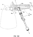
- a pod assembly is shown generally at 10. Furthermore, as seen in FIGS. 18A-18B , a firearm implement system including a pod assembly 10a and a firearm F is shown generally at 100. Yet even further, as seen in FIGS. 19A-19B , a firearm implement system including a first pod assembly 10a, a second pod assembly 10b and a firearm F is shown generally at 200.
- the pod assembly 10a of the firearm implement system 100 and the first and second pod assemblies 10a, 10b of the firearm implement system 200 may be substantially similar to the pod assembly 10 of FIGS. 1A-1C , 14A-14D and 15A-15D .
- the pod assembly 10 includes a leg indexing portion 12.
- the pod assembly 10 may optionally include a telescoping leg portion 14 connected to the leg indexing portion 12; because the leg indexing portion 12 can, in-of-itself, is shaped to be in the form of a leg or a support member for supporting a device (such as, e.g., a camera, firearm (F, as seen in, for example, FIGS. 18A-18B , 19A-19B ) or the like), the telescoping leg portion 14 may operate to extend the leg shape of the leg indexing portion 12, and, as a result, the telescoping leg portion 14 is not a critical or essential component of the pod assembly 10.
- the telescoping leg portion 14 includes a shaft portion 16. At least a distal portion 16 D of the shaft portion 16 is adjustably-disposed within the leg indexing portion 12 (see, e.g., FIGS. 15A-15D ). In an implementation, the shaft portion 16 is movably-disposed relative to the leg indexing portion 12 along an axis A-A that coaxially extends through both of the leg indexing portion 12 and the telescoping leg portion 14.
- the telescoping leg portion 14 may further include a foot portion 18 that is attached to a proximal portion 16 P of the shaft portion 16.
- the telescoping leg portion 14 may further include a retainer portion 20 that selectively-retains the shaft portion 16 in a selectively-fixed orientation relative the leg indexing portion 12 after the shaft portion 16 has been selectively extended from the leg indexing portion 12 or selectively disposed within the leg indexing portion 12.
- the leg indexing portion 12 includes an indexing plate 22 and a biased latch subassembly 24.
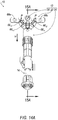
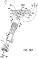
- the leg indexing portion 12 further includes a pivot pin 26 that pivotably-connects (see, e.g., arrows P / P' in FIGS. 14A-14D ) the biased latch subassembly 24 to the indexing plate 22.
- the biased latch subassembly 24 includes a shaft body 28.
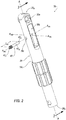
- the shaft body 28 defines: a pivot-pin-receiving passage 30a, a rocker-latch-receiving passage 30b, at least one (e.g. a pair of) latch pin-receiving passage(s) 30c and a telescoping-leg-portion-receiving passage 30d (see, e.g., FIG. 3 ).
- the pivot-pin-receiving passage 30a radially extends through the shaft body 28 (relative to the axis A-A) proximate a distal end 28 D of the shaft body 28.
- the rocker-latch-receiving passage 30b radially extends (see, e.g., axis A 30b -A 30b ) through the shaft body 28 (relative to the axis A-A) proximate the distal end 28 D of the shaft body 28 but nearer to a proximal end 28 P of the shaft body 28 with respect to the pivot-pin-receiving passage 30a.
- the pair of latch pin-receiving passages 30c radially extends (see, e.g., axis A 30c -A 30c ) through the shaft body 28 (relative to the axis A-A) proximate the distal end 28 D of the shaft body 28 but nearer to the proximal end 28 P of the shaft body 28 with respect to the pivot-pin-receiving passage 30a. Furthermore, as seen in FIGS. 1A , 2 and 3 , the pair of latch pin-receiving passages 30c radially traverses and is in fluid communication with the rocker-latch-receiving passage 30b.
- the pair of latch pin-receiving passages 30c are radially offset from the rocker-latch-receiving passage 30b by approximately 180° (see, e.g., axis A 30c -A 30c extending through the pair of latch pin-receiving passages 30c compared to axis A 30b -A 30b extending through the rocker-latch-receiving passage 30b).
- the telescoping-leg-portion-receiving passage 30d partially axially extends into the shaft body 28 from the proximal end 28 P of the shaft body 28 along the axis A-A. Furthermore, the telescoping-leg-portion-receiving passage 30d extends toward but not all the way to the distal end 28 D of the shaft body 28.
- the telescoping-leg-portion-receiving passage 30d extends toward the distal end 28 D of the shaft body 28 but not past the rocker-latch-receiving passage 30b, which is nearest to the proximal end 28 P of the shaft body 28 with respect to the pivot-pin-receiving passage 30a and the pair of latch pin-receiving passages 30c.
- the rocker-latch-receiving passage 30b may be defined an inner surface 32.
- the inner surface 32 of the rocker-latch-receiving passage 30b may be alternatively referred to as a radial biasing member engagement surface.
- the shaft body 28 may be further defined by an outer surface portion 34.
- the outer surface portion 34 may be defined by at least: a first axial surface portion 34a, a second axial surface portion 34b and a radial surface portion 34c that connects the first axial surface portion 34a to the second axial surface portion 34b.
- the radial surface portion 34c may be alternatively referred to as an axial biasing member engagement surface.
- first axial surface portion 34a may be defined by a length portion L 34a including a first length portion segment L 34a-1 that extends axially away from the axial biasing member engagement surface 34c and a second length portion segment L 34a-2 that extends axially away from the first length portion segment L 34a-1 .
- second axial surface portion 34b may be defined by a length portion L 34b including a first length portion segment L 34b-1 that extends axially away from the axial biasing member engagement surface 34c and a second length portion segment L 34b-2 that extends axially away from the first length portion segment L 34b-1 .
- At least some of the first axial surface portion 34a of the outer surface portion 34 may define a first outer diameter D 28-1 of the shaft body 28. At least some of the second axial surface portion 34b of the outer surface portion 34 may define a second outer diameter D 28-2 of the shaft body 28. The second outer diameter D 28-2 may be greater than the first outer diameter D 28-1 .
- the biased latch subassembly 24 further includes a radial biasing member 36 (see, e.g., FIGS. 4-5 ) and a rocker latch 38 (see, e.g., FIGS. 6-7 ).
- the radial biasing member 36 and the rocker latch 38 are disposed within the rocker-latch-receiving passage 30b of the shaft body 28 (see, e.g., FIGS. 15A-15D ).
- the radial biasing member 36 may be a coil spring.
- the radial biasing member 36 may be defined by a proximal end 36 P and a distal end 36 D .
- the rocker latch 38 may define a latch pin-receiving passage 40 extending through a width W 38 (see, e.g., FIG. 6 ) of the rocker latch 38.
- An axis A 40 -A 40 extends through the latch pin-receiving passage 40 of the rocker latch 38.
- the axis A 40 -A 40 extending through the latch pin-receiving passage 40 of the rocker latch 38 is co-axially aligned with the axis A 30c -A 30c extending through the pair of latch pin-receiving passages 30c of the shaft body 28.
- the biased latch subassembly 24 further includes a latch pin 42.
- the latch pin 42 is aligned with the axis A 30c -A 30c (see also, e.g., FIG. 2 ) extending through the pair of latch pin-receiving passages 30c of the shaft body 28 and the axis A 40 -A 40 extending through the latch pin-receiving passage 40 of the rocker latch 38.
- the latch pin 42 is disposed within is the pair of latch pin-receiving passages 30c of the shaft body 28 and the latch pin-receiving passage 40 of the rocker latch 38 (as seen in FIGS. 1B-1C ) for rotatably-connecting R (see, e.g., FIG. 15B ) / R' (see, e.g., FIG. 15D ) the rocker latch 38 to the shaft body 28.
- the latch pin 42 includes a proximal end 42 P and a distal end 42 D .
- the latch pin 42 is defined by a length L 42 extending between the proximal end 42 P of the latch pin 42 and the distal end 42 D of the latch pin 42.
- the length L 42 of latch pin 42 may be greater than the first outer diameter D 28-1 defined by the first axial surface portion 34a of the shaft body 28 such that when the latch pin 42 is disposed within the pair of latch pin-receiving passages 30c of the shaft body 28, at least, for example the distal end 42 D of the latch pin 42 extends radially beyond the outer surface portion 34 of the shaft body 28 (as seen in, e.g., FIG.
- the radial biasing member 36 is arranged within the rocker-latch-receiving passage 30b of the shaft body 28.
- the radial biasing member 36 is arranged between the radial biasing member engagement surface 32 of the rocker-latch-receiving passage 30b and a radial-outwardly-urging surface 32' (see also, e.g., FIG.
- the shaft portion 16 of the telescoping leg portion 14 is aligned with the axis A-A extending through the telescoping-leg-portion-receiving passage 30d of the shaft body 28 of the leg indexing portion 12. Furthermore, as seen in FIGS. 15A-15D , the shaft portion 16 of the telescoping leg portion 14 is disposed within the telescoping-leg-portion-receiving passage 30d of the shaft body 28 of the leg indexing portion 12 for telescopingly-connecting the shaft portion 16 of the telescoping leg portion 14 to the shaft body 28 of the leg indexing portion 12.
- the shaft portion 16 of the telescoping leg portion 14 may be slidably-adjusted into and out of the telescoping-leg-portion-receiving passage 30d of the shaft body 28 of the leg indexing portion 12 and selectively-fixed in any desirable retracted or extended position by engaging or disengaging the retainer portion 20 of the telescoping leg portion 14.
- the biased latch subassembly 24 further includes an axial biasing member 44.
- the axial biasing member 44 may be a coil spring having a proximal surface 44 P , a distal surface 44 D , an inner surface 44 I (see, e.g., FIG. 9 ) and an outer surface 44o.
- the inner surface 44 I of the axial biasing member 44 defines a passage 46 extending through the axial biasing member 44 between the proximal surface 44p and the distal surface 44 D .
- the inner surface 44 I of the axial biasing member 44 also defines a passage diameter D 46 of the passage 46.
- the outer surface 44o of the axial biasing member 44 defines an outer diameter D 44-O of the axial biasing member 44.
- the passage diameter D 46 of the passage 46 of the axial biasing member 44 is approximately equal to but slightly greater than the first outer diameter D 28-1 defined by the first axial surface portion 34a of the outer surface portion 34 of the shaft body 28; furthermore, the outer diameter D 44-O of the axial biasing member 44 is approximately equal to but slightly less than the second outer diameter D 28-2 defined by the second axial surface portion 34b of the outer surface portion 34 of the shaft body 28.
- the axial biasing member 44 is co-axially aligned with the axis A-A, and the proximal surface 44 P of the axial biasing member 44 is arranged opposite the axial biasing member engagement surface 34c of the outer surface portion 34 of the shaft body 28. Thereafter, as seen in FIGS.
- the distal end 28 D of the shaft body 28 is inserted through passage 46 of the axial biasing member 44 such that the inner surface 44 I of the axial biasing member 44 is arranged opposite some of the first axial surface portion 34a of the outer surface portion 34 of the shaft body 28 and the proximal surface 44 P of the axial biasing member 44 is arranged adjacent and supported by the axial biasing member engagement surface 34c of the outer surface portion 34 of the shaft body 28.
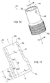
- the biased latch subassembly 24 further includes a latch actuator pull sleeve 48 (see, e.g., FIGS. 10-11 ) and rocker latch-engaging finger 50 (see, e.g., FIGS. 12-13 ).
- the rocker latch-engaging finger 50 includes a head portion 51 and a stem portion 53.
- the latch actuator pull sleeve 48 includes a sleeve body 52 defining an axial passage 54a and a radial passage 54b that is in fluid communication with the axial passage 54a; furthermore, as seen in FIGS. 15A-15D , the radial passage 54b is also in fluid communication with the rocker-latch-receiving passage 30b when the latch actuator pull sleeve 48 is arranged about the shaft body 28.
- the shaft body 28 is arranged within the axial passage 54a and a portion of the stem portion 53 rocker latch-engaging finger 50 extends through the radial passage 54b and into the rocker-latch-receiving passage 30b of the shaft body 28 as a result of the latch actuator pull sleeve 48 circumscribing a portion of the rocker-latch-receiving passage 30b of the shaft body 28.
- a portion of the length of the latch actuator pull sleeve 48 including the radial passage 54b that retains the portion of the stem portion 53 of the rocker latch-engaging finger 50 circumscribes a portion of the rocker-latch-receiving passage 30b of the shaft body 28 such that a rocker-latch-engaging surface 56 (see also, e.g., FIGS. 12-13 ) of the stem portion 53 of the rocker latch-engaging finger 50 is permitted to be disposed adjacent and slidably-engage a radial-inwardly-urging surface 56' (see also, e.g., FIG. 7 ) of the rocker latch 38.
- the radial-inwardly-urging surface 56' is generally defined as having a proximal end 56 P (see, e.g., FIGS. 6-7 ) and a distal end 56 D (see, e.g., FIGS. 6-7 ).
- the sleeve body 52 may be further defined by an inner surface 58 that defines the axial passage 54a.
- the inner surface 58 may be defined by at least: a first axial surface portion 58a, a second axial surface portion 58b and a radial surface portion 58c that connects the first axial surface portion 58a to the second axial surface portion 58b.
- the radial surface portion 58c may be alternatively referred to as an axial biasing member urging surface.
- the second axial surface portion 58b may be defined by a length portion L 58b including a first length portion segment L 58b-1 , a second length portion segment L 58b-2 and a third length portion segment L 58b-3 .
- the first length portion segment L 58b-1 extends axially away from a proximal end 52 P of the sleeve body 52.
- the second length portion segment L 58b-2 extends axially away from the first length portion segment L 58b-1 and is arranged axially between the first length portion segment L 58b-1 and the third length portion segment L 58b-3 .
- the third length portion segment L 58b-3 extends axially away from the second length portion segment L 58b-2 and is arranged axially between the second length portion segment L 58b-2 and the axial biasing member urging surface 58c.
- the first axial surface portion 58a of the inner surface 58 may define a first passage diameter D 54a-1 of the axial passage 54a.
- the second axial surface portion 58b of the inner surface 58 may define a second passage diameter D 54a-2 of the axial passage 54a.
- the second passage diameter D 54a-2 may be greater than the first passage diameter D 54a-1 .
- the first passage diameter D 54a-1 of the axial passage 54a defined by the inner surface 58 of the sleeve body 52 is approximately equal to but slightly greater than the first outer diameter D 28-1 defined by the first axial surface portion 34a of the shaft body 28.
- the second passage diameter D 54a-2 of the axial passage 54a defined by the inner surface 58 of the sleeve body 52 is approximately equal to but slightly greater than the second outer diameter D 28-2 defined by the second axial surface portion 34b of the shaft body 28.
- the latch actuator pull sleeve 48 is aligned with the axis A-A, and the axial biasing member urging surface 58c of the inner surface 58 of the sleeve body 52 of the latch actuator pull sleeve 48 is arranged opposite the distal surface 44 D of the axial biasing member 44.
- the distal end 28 D of the shaft body 28 is inserted through axial passage 54a defined by the inner surface 58 of the sleeve body 52 of the latch actuator pull sleeve 48 for arranging the inner surface 58 of the sleeve body 52 about the outer surface portion 34 of the shaft body 28 such that: (1) the first length portion segment L 58b-1 of the length portion L 58b of the second axial surface portion 58b of the inner surface 58 of the sleeve body 52 is arranged opposite the first length portion segment L 34b-1 of the length portion L 34b of the second axial surface portion 34b of the shaft body 28, (2) the second and third length portion segments L 58b-2 , L 58b-3 of the length portion L 58b of the second axial surface portion 58b of the inner surface 58 of the sleeve body 52 is arranged opposite the first and second length portion segments L 34a-1 , L 34a-2 of the length portion L 34a of the first axial surface portion
- an axial biasing member cavity 60 is defined by: (1) the second and third length portion segments L 58b-2 , L 58b-3 of the length portion L 58b of the second axial surface portion 58b of the inner surface 58 of the sleeve body 52 being arranged radially opposite the first and second length portion segments L 34a-1 , L 34a-2 of the length portion L 34a of the first axial surface portion 34a of the shaft body 28 and (2) the axial biasing member engagement surface 34c of the shaft body 28 being arranged axially opposite the axial biasing member urging surface 58c of the inner surface 58 of the sleeve body 52 of the latch actuator pull sleeve 48.
- the axial biasing member cavity 60 thereby provides a pair of axially opposite surfaces (see, e.g., surfaces 34c, 58c) and a pair of radially opposite surfaces (see, e.g., portions of surfaces 34a, 58b) that axially and radially retains the axial biasing member 44 between shaft body 28 and the sleeve body 52.
- the latch pin 42 is disposed within is the pair of latch pin-receiving passages 30c of the shaft body 28 and the latch pin-receiving passage 40 of the rocker latch 38 after the sleeve body 52 has been arranged relative the shaft body 28 as described above.
- the axial biasing member 44 being axially retained within the axial biasing member cavity 60 as described above, the axial biasing member axially urges Y (see, e.g., FIGS. 15A-15D ) a distal end 52 D (see also, e.g., FIG. 11 ) of the sleeve body 52 adjacent the outer surface 42o of the latch pin 42 (as seen in FIG.
- the distal end 36 D of radial biasing member 36 is disposed adjacent the radial-outwardly-urging surface 32' of the rocker latch 38 for imparting a radially-outwardly bias X to the rocker latch 38 such that the rocker-latch-engaging surface 56 of the rocker latch-engaging finger 50 is disposed adjacent (for slidable engagement with) the radial-inwardly-urging surface 56' of the rocker latch 38.
- FIGS. 15A-15D in conjunction with the axial bias Y imparted to the sleeve body 52 by the axial biasing member 44 as described above, the distal end 36 D of radial biasing member 36 is disposed adjacent the radial-outwardly-urging surface 32' of the rocker latch 38 for imparting a radially-outwardly bias X to the rocker latch 38 such that the rocker-latch-engaging surface 56 of the rocker latch-engaging finger 50 is disposed adjacent (for slidable engagement with) the radial
- the rocker latch 38 may define a stem portion-receiving channel 62 defined by the radial-inwardly-urging surface 56' and a pair of opposing channel sidewall surfaces 57.
- the stem portion 53 of the rocker latch-engaging finger 50 may be defined by a width W 53 (see, e.g., FIGS. 12-13 ) that is substantially similar to but less than a width W 62 (see, e.g., FIG.
- the stem portion 53 of the rocker latch-engaging finger 50 may be slidably-retained adjacent the rocker latch 38 for slidable movement between the proximal end 56 P of the radial-inwardly-urging surface 56' and the distal end 56 D of the radial-inwardly-urging surface 56'.
- the radial-inwardly-urging surface 56' of the rocker latch 38 defines a ramp surface that progressively projects radially outwardly at a ramp angle ⁇ (see, e.g., FIG. 7 ) relative to the axis A-A that coaxially extends through both of the leg indexing portion 12 and the telescoping leg portion 14 as the radial-inwardly-urging surface 56' extends from, for example, the distal end 56 D to the proximal end 56 P .
- the ramp angle ⁇ may be approximately equal to 15°.
- rocker latch-engaging finger 50 is radially fixed within the radial passage 54b of the sleeve body 52 of the latch actuator pull sleeve 48 against the ramp surface / radial-inwardly-urging surface 56' and because the radial biasing member 36 imparts the radially-outwardly bias X to the rocker latch 38, when the latch actuator pull sleeve 48 is pulled downwardly Y' (see, e.g., FIGS. 15B-15C ) toward the proximal end 28 P of the shaft body 28, the latch-engaging finger 50 remains disposed adjacent the ramp surface / radial-inwardly-urging surface 56' and urges rotation R (see, e.g., FIG.
- the axial biasing member cavity 60 is no longer defined by the second and third length portion segments L 58b-2 , L 58b-3 of the length portion L 58b of the second axial surface portion 58b of the inner surface 58 of the sleeve body 52 being arranged radially opposite the first and second length portion segments L 34a-1 , L 34a-2 of the length portion L 34a of the first axial surface portion 34a of the shaft body 28.
- the axial bias Y of the axial biasing member 44 urges the sleeve body 52 upwardly (see direction of the axial bias arrow Y) toward the distal end 28 D of the shaft body 28 until the distal end 52 D of the sleeve body 52 is disposed adjacent the outer surface 42o of the latch pin 42 (as seen in FIG. 1C ) as a result of, for example, the distal end 42 D of the latch pin 42 extending radially beyond the outer surface portion 34 of the shaft body 28.
- the latch-engaging finger 50 remains disposed adjacent the ramp surface 56' and slides upwardly (see direction of the axial bias arrow Y from the proximal end 56 P to the distal end 56 D ) with the sleeve body 52.
- the indexing plate 22 may include a plate body 64.
- the plate body 64 may generally define a firearm-engaging body portion 64a and a biased latch subassembly-engaging body portion 64b.
- the firearm-engaging body portion 64a includes an inner surface 64a I , an outer surface 64ao, an upper surface 64au and a lower surface 64a L .
- the firearm-engaging body portion 64a may be further defined by a thickness T 64a extending between the inner surface 64a I and the outer surface 64ao.
- the firearm-engaging body portion 64a may be further defined by a central body portion 64ac, a first lateral body portion 64a L1 and a second lateral body portion 64a L2 .
- the first lateral body portion 64a L1 may be defined as having a proximal end 64a L1-P and a distal end 64a L1-D .
- the second lateral body portion 64a L2 may be defined as having a proximal end 64a L2-P and a distal end 64a L2-D .
- the central body portion 64ac extends between the proximal end 64a L1-P of the first lateral body portion 64a L1 and the proximal end 64a L2-P of the second lateral body portion 64a L2 .
- a first fastener passage 66a may be defined by the first lateral body portion 64a L1 .
- a second fastener passage 66b may be defined by the second lateral body portion 64a L2 .
- the first and second fastener passages 66a, 66b extend through the thickness T 64a of the firearm-engaging body portion 64a.
- the biased latch subassembly-engaging body portion 64b extends from one or both of the outer surface 64ao and the lower surface 64a L of the firearm-engaging body portion 64a. In an example, as seen in FIG.
- the biased latch subassembly-engaging body portion 64b extends from one or both of the outer surface 64ao and the lower surface 64a L of the firearm-engaging body portion 64a between the proximal end 64a L1-P of the first lateral body portion 64a L1 and the proximal end 64a L2-P of the second lateral body portion 64a L2 ; as a result, the biased latch subassembly-engaging body portion 64b may be defined as extending from the central body portion 64ac of the firearm-engaging body portion 64a.
- the biased latch subassembly-engaging body portion 64b extends away from the outer surface 64ao of the firearm-engaging body portion 64a at a biased latch subassembly-engaging body portion angle ⁇ .
- the biased latch subassembly-engaging body portion angle ⁇ may be referenced from a first reference plane P1 aligned with and extending across the outer surface 64bo of the biased latch subassembly-engaging body portion 64b and a second reference plane P2 aligned with and extending across the outer surface 64ao of the firearm-engaging body portion 64a.
- the biased latch subassembly-engaging body portion angle ⁇ may be approximately equal to 20°.
- the second reference plane P2 aligned with and extending across the outer surface 64ao of the firearm-engaging body portion 64a may be substantially parallel to a third reference plane P3 aligned with and extending across the inner surface 64a I of the firearm-engaging body portion 64a.
- the outer surface 64bo of the biased latch subassembly-engaging body portion 64b may define a plurality of rocker latch-receiving recesses 66 that extend into a thickness T 64b (see, e.g., FIG. 17A ) of the biased latch subassembly-engaging body portion 64b at a depth D 64b (see, e.g., FIG. 17A ).
- the thickness T 64b may be bound by the outer surface 64bo of the biased latch subassembly-engaging body portion 64b and an inner surface 64b I (see, e.g., FIGS. 17A-17C ) of the biased latch subassembly-engaging body portion 64b.
- the depth D 64b is not equal to the thickness T 64b of the biased latch subassembly-engaging body portion 64b, and as a result, the plurality of rocker latch-receiving recesses 66 do not extend through the entire thickness T 64b of the biased latch subassembly-engaging body portion 64b.
- the outer surface 64b o of the biased latch subassembly-engaging body portion 64b that defines each rocker latch-receiving recesses 66 0 , 66 +1 , 66 +2 , 66 -1 , 66 -2 of the plurality of rocker latch-receiving recesses 66 includes a recess surface 68 B and a perimeter recess surface 68 P .
- the perimeter recess surface 68 P is connected to and may extend substantially perpendicularly from the outer surface 64bo of the biased latch subassembly-engaging body portion 64b.
- the recess surface 68 B is connected to and may extend substantially perpendicularly from the perimeter recess surface 68 P . As seen in FIG. 17A , the perimeter recess surface 68 P extends between the recess surface 68 B and the outer surface 64bo of the biased latch subassembly-engaging body portion 64b at a distance approximately equal to the depth D64b.
- the plurality of rocker latch-receiving recesses 66 may include at least two (see, e.g., reference numerals 66 0 , 66 +1 , 66 +2 , 66 -1 , 66 -2 ) rocker latch-receiving recesses 66.
- the plurality of rocker latch-receiving recesses 66 includes five rocker latch-receiving recesses 66 0 , 66 +1 , 66 +2 , 66 -1 , 66 -2 defined by, for example: a neutral leg orientation recess 66 0 , a first positively-indexed leg orientation recess 66 +1 , a second positively-indexed leg orientation recess 66 +2 , a first negatively-indexed leg orientation recess 66 -1 and a second negatively-indexed leg orientation recess 66 -2 .
- the plurality of rocker latch-receiving recesses 66 are arranged in an arcuate orientation to permit selective pivotable adjustment (in a positive direction according to arrow P or a negative direction according to arrow P') of the biased latch subassembly 24 in one of a plurality of orientations along, for example, a 180° arc as seen in FIGS. 14A-14D . According to the illustrated example at FIGS.
- the five rocker latch-receiving recesses 66 0 , 66 +1 , 66 +2 , 66 -1 , 66 -2 permit the biased latch subassembly 24 to be pivotally-adjusted P / P' (see, e.g., FIGS. 14A-14D ) relative the indexing plate 22 from, for example, a neutral orientation (see, e.g., FIG.
- any desirable orientation such as, for example: (1) a first forward orientation pivoted +45° from the neutral for registration within the first positively-indexed leg orientation recess 66 +1 , (2) a second forward orientation pivoted +90° from the neutral for registration within the second positively-indexed leg orientation recess 66 +2 , (3) a first rearward orientation pivoted -45° from the neutral for registration within the first negatively-indexed leg orientation recess 66 -1 or (4) a second rearward orientation pivoted -90° from the neutral for registration within the second negatively-indexed leg orientation recess 66 -2 .
- the plate body 64 may further define a pivot-pin-receiving passage 70.
- the pivot-pin-receiving passage 70 may extend through both of the firearm-engaging body portion 64a and the biased latch subassembly-engaging body portion 64b between the inner surface 64a I of the firearm-engaging body portion 64a and the outer surface 64bo of the biased latch subassembly-engaging body portion 64b.
- the pivot-pin-receiving passage 70 may be formed in an axial center 72 of the arcuate orientation of the plurality of rocker latch-receiving recesses 66.
- the pivot-pin-receiving passage 70 of the plate body 64 of the indexing plate 22 is co-axially aligned with the axis A 30a -A 30a extending through the pivot-pin-receiving passage 30a of the shaft body 28 of the biased latch subassembly 24.
- the pivot pin 26 is disposed within the pivot-pin-receiving passages 30a, 70 of the shaft body 28 and the plate body 64 for pivotally-connecting P the biased latch subassembly 24 to the indexing plate 22.
- the pod assembly 10 may be utilized by a user.
- the user may apply the pulling force (see, e.g., arrow Y') to the latch actuator pull sleeve 48 for overcoming the axial bias (see, e.g., arrow Y) and radial bias (see, e.g., arrow X) of the axial biasing member 44 and the radial biasing member 36 as described above.
- the rocker latch 38 is rotated R / R' as described above in response to the pulling force Y' / the axial bias Y described above, a head portion 74 (see, e.g., FIGS.
- rocker latch 38 may be registered within / de-registered from any rocker latch-receiving recesses 66 0 , 66 +1 , 66 +2 , 66 -1 , 66 -2 of the plurality of rocker latch-receiving recesses 66.
- the axial bias Y imparted by the axial biasing member 44 may be translated through intervening structure (see, e.g., reference numerals 38, 48, 50) of the biased latch subassembly 24 such that the radial bias X imparted by the radial biasing member 36 may rotationally urge (see, e.g., arrow R' in FIGS.
- the mounting rail R S1 may be one mounting rail of a plurality of mounting rails of the firearm F.
- the firearm F may include seven mounting rails including, for example, a first lateral side mounting rail R S1 , a second lateral side mounting rail R S2 (see, e.g., FIG. 18B ), an upper mounting rail R U , a first upper-intermediate side mounting rail R S1-UI , a first lower-intermediate side mounting rail R S1-LI , a second upper-intermediate side mounting rail R S2-UI (see, e.g., FIG.
- the fasteners 102a, 102b are interested into the first and second fastener passages 66a, 66b of the indexing plate 22 as described above, the fasteners 102a, 102b are further extended into corresponding fastener passages (not shown) formed by the first lateral side mounting rail R S1 of the firearm F.
- the inner surface 64a I of the firearm-engaging body portion 64a of the plate body 64 of each indexing plate 22 may include one or more (e.g., two) rail registration projections 76.
- the rail registration projections 76 may be inserted into passages (not shown) formed by the first lateral side mounting rail R S1 of the firearm F prior to the fasteners 102a, 102b being extended into corresponding fastener passages (not shown) formed by the first lateral side mounting rail R S1 of the firearm F.
- the first fastener passage 66a defined by the first lateral body portion 64a L1 of the firearm-engaging body portion 64a of the plate body 64 of the indexing plate 22 and the second fastener passage 66b defined by the second lateral body portion 64a L2 of the firearm-engaging body portion 64a of the plate body 64 of the indexing plate 22 may be automatically-aligned with corresponding passages formed by the first lateral side mounting rail R S1 of the firearm F for receiving the fasteners 102a, 102b.
- the pod assembly 10a when the pod assembly 10a is attached to the first lateral side mounting rail R S1 of the firearm F, the pod assembly 10a may function as a mono-pod.
- a user may desire the pod assembly 10a to act as a mono-pod extending from a side portion (i.e., the region of the firearm F generally defined by the first lateral side mounting rail R S1 of the firearm F) and not the bottom portion (i.e., the region of the firearm F generally defined by the bottom side of the firearm F where a lower mounting rail is not provided) of the firearm F whereby the user desires to utilize a portion of the ambient environment (see, e.g., a rock or boulder B in FIGS.
- the pod assembly 10a may also (or alternatively) function as a hand grip extending from, for example, a side portion (i.e., the region of the firearm F generally defined by the first lateral side mounting rail R S1 of the firearm F) and not the bottom portion (e.g., the region of the firearm F generally defined by the bottom side of the firearm F where a lower mounting rail is not provided) of the firearm F.
- a side portion i.e., the region of the firearm F generally defined by the first lateral side mounting rail R S1 of the firearm F
- the bottom portion e.g., the region of the firearm F generally defined by the bottom side of the firearm F where a lower mounting rail is not provided
- the first outer diameter D 28-1 and the second outer diameter D 28-2 of the shaft body 28 of the leg indexing portion 12 may be sized for receiving a user's hand, palm or fingers arranged there-about.
- a firearm axis F-F (see also FIG. 18A ) is co-axial with a central axis extending along the entire length of the firearm F.
- a firearm plane F1 that is substantially orthogonal to an underlying ground surface G intersects with the firearm axis F-F and the axis A-A extending through the pod assembly 10a.
- the first reference plane P1 is substantially parallel to the axis A-A extending through the pod assembly 10a.
- each of the second reference plane P2 and the third reference plane P3 is substantially parallel to the firearm plane F1.
- the biased latch subassembly-engaging body portion angle ⁇ also defines a firearm support angle ⁇ '.
- the firearm support angle ⁇ ' is bound by the axis A-A and the firearm plane F1. Therefore, in an example, if the biased latch subassembly-engaging body portion angle ⁇ is approximately equal to 20°, then the firearm support angle ⁇ ' is also approximately equal to 20°.
- any pivoting movement P / P' of the leg indexing portion 12 of the first pod assembly 10a relative the firearm F is limited according to the arrows P / P' (see, e.g., FIGS. 14A-14D ).
- the pod assembly 10a is not pivotably-configured in a manner to 'collapse' the leg indexing portion 12 relative the firearm F by, for example, reducing the firearm support angle ⁇ ' (in order to, for example, pivotably-adjust the leg indexing portion 12 in a manner for locating, as an example, the optional foot portion 18 of the optional telescoping leg portion 14 substantially below or under either of the first lower-intermediate side mounting rail R S1-LI or the second lower-intermediate side mounting rail R S2-LI .
- the pod assembly 10a is pivotably-configured in a manner to 'collapse' the leg indexing portion 12 relative the firearm F by, for example, pivoting P' the biased latch subassembly 24 relative the indexing plate 22 such that the head portion 74 of the rocker latch 38 is registered within the second negatively-indexed leg orientation recess 66 -2 such that the biased latch subassembly 24 is pivoted P' relative the indexing plate 22 to the second rearward orientation -90° in order to arrange the biased latch subassembly 24 along the barrel of the firearm F.
- a first exemplary pod assembly 10a and a second exemplary pod assembly 10b which may both be substantially similar to the pod assembly 10 described above, are shown attached to a firearm F for forming a firearm implement system 200.
- the pod assembly 10a is shown attached to a first mounting rail R S1 of the firearm F and the pod assembly 10b is shown attached to a second mounting rail R S2 of the firearm F that is opposite the first mounting rail R S1 of the firearm F.
- the first mounting rail R S1 may be one mounting rail of a plurality of mounting rails of the firearm F; furthermore, in an example, the second mounting rail R S2 may be another mounting rail of a plurality of mounting rails of the firearm F.
- the firearm F may include seven mounting rails including, for example, a first lateral side mounting rail R S1 , a second lateral side mounting rail R S2 and an upper mounting rail R U , a first upper-intermediate side mounting rail R S1-UI , a first lower-intermediate side mounting rail R S1-LI , a second upper-intermediate side mounting rail R S2-UI (see, e.g., FIG.
- each of the mounting rails R S1 , R S1-UI , R S1-LI , R S2 , R S2-UI , R S2-LI , R U described above is not a lower mounting rail (that would be located directly opposite the upper mounting rail R U ), and, as seen in FIGS. 19A-19B , the firearm F does not include a lower mounting rail.
- the first pod assembly 10a is shown attached to the first lateral side mounting rail R S1 and the second pod assembly 10b is shown attached to the second lateral side mounting rail R S2 .
- the indexing plate 22 of the leg indexing portion 12 of the first pod assembly 10a is only attached to the first lateral side mounting rail R S1 and not to any other mounting rail (e.g., the second lateral side mounting rail R S2 and the upper mounting rail R U ) of the plurality of mounting rails; furthermore, in such an exemplary implementation, when the second pod assembly 10b is attached to the second lateral side mounting rail R S2 , the indexing plate 22 of the leg indexing portion 12 of the second pod assembly 10b is only attached to the second lateral side mounting rail R S2 and not to any other mounting rail (e.g., the first lateral side mounting rail R S1 and the upper mounting rail R U ) of the plurality of mounting rails.
- the indexing plate 22 of the leg indexing portion 12 of each of the first pod assembly 10a and the second pod assembly 10b is attached, respectively, to the first lateral side mounting rail R S1 and the second lateral side mounting rail R S2 by firstly inserting: (1) a fastener 102a through the first fastener passage 66a defined by the first lateral body portion 64a L1 of the firearm-engaging body portion 64a of the plate body 64 of the indexing plate 22 and (2) a fastener 102b through the second fastener passage 66b defined by the second lateral body portion 64a L2 of the firearm-engaging body portion 64a of the plate body 64 of the indexing plate 22.
- the fasteners 102a, 102b are interested into the first and second fastener passages 66a, 66b of the indexing plate 22 as described above, the fasteners 102a, 102b are further extended into corresponding fastener passages (not shown) formed respectively by the first lateral side mounting rail R S1 and the second lateral side mounting rail R S2 of the firearm F.
- the first pod assembly 10a and the second pod assembly 10b may cooperate with the firearm F to function as a bi-pod.
- either of the first pod assembly 10a or the second pod assembly 10b may also (or alternatively) function as a hand grip extending from, for example, a side portion (e.g., the region of the firearm F generally defined by the first lateral side mounting rail R S1 or the second lateral side mounting rail R S2 of the firearm F) and not the bottom portion (i.e., the region of the firearm F generally defined by the bottom side of the firearm F where a lower mounting rail is not provided) of the firearm F.
- a side portion e.g., the region of the firearm F generally defined by the first lateral side mounting rail R S1 or the second lateral side mounting rail R S2 of the firearm F
- the bottom portion i.e., the region of the firearm F generally defined by the bottom side of the firearm F where a lower mounting rail is not provided
- the first outer diameter D 28-1 and the second outer diameter D 28-2 of the shaft body 28 of the leg indexing portion 12 may be sized for receiving a user's hand, palm or fingers arranged there-about
- the fastener passages formed respectively by the first lateral side mounting rail R S1 and the second lateral side mounting rail R S2 of the firearm F may include any desirable geometry such as, for example, a 'keymod' geometry.
- the indexing plate 22 may be designed to include an alternative attachment geometry for attaching the respective indexing plates 22 to the first lateral side mounting rail R S1 and the second lateral side mounting rail R S2 of the firearm F in another manner; for example, the inner surface 64a I of the firearm-engaging body portion 64a of the plate body 64 of each indexing plate 22 may be formed to include a 'Weaver-style' or 'Picatinny-style' geometry that interfaces with a corresponding 'Weaver-style' or 'Picatinny-style' geometry of, respectively, the first lateral side mounting rail R S1 and the second lateral side mounting rail R S2 of
- the inner surface 64a I of the firearm-engaging body portion 64a of the plate body 64 of each indexing plate 22 may include one or more (e.g., two) rail registration projections 76.
- the rail registration projections 76 may be inserted into passages (not shown) formed by the first lateral side mounting rail R S1 of the firearm F prior to the fasteners 102a, 102b being extended into corresponding fastener passages (not shown) formed by the first lateral side mounting rail R S1 of the firearm F.
- a firearm axis F-F (see also FIG. 19A ) is co-axial with a central axis extending along the entire length of the firearm F.
- a firearm plane F1 that is substantially orthogonal to an underlying ground surface G intersects with the firearm axis F-F and the axis A-A extending through the pod assembly 10a.
- the first reference plane P1 of each of the first pod assembly 10a and the second pod assembly 10b is substantially parallel to the axis A-A extending through each pod assembly 10a, 10b.
- each of the second reference plane P2 and the third reference plane P3 of each of the first pod assembly 10a and the second pod assembly 10b is substantially parallel to the firearm plane F1.
- the third reference plane P3 of each of the first pod assembly 10a and the second pod assembly 10b is aligned with a lateral side rail plane (not shown); with respect to the first pod assembly 10a, the lateral side rail plane is aligned with and extending across an outer surface (not shown) first lateral side mounting rail R S1 of the firearm F, and, with respect to the second pod assembly 10b, the lateral side rail plane is aligned with and extending across an outer surface (not shown) second lateral side mounting rail R S2 of the firearm F.
- the third reference plane P3 may also be the lateral side rail plane of: the first lateral side mounting rail R S1 (with respect to the first pod assembly 10a), and, respectively, the second lateral side mounting rail R S2 (with respect to the second pod assembly 10b) when the first pod assembly 10a and the second pod assembly 10b are attached to the firearm F.
- the biased latch subassembly-engaging body portion angle ⁇ also defines a firearm support angle ⁇ ' of each of the first pod assembly 10a and the second pod assembly 10b.
- the firearm support angle ⁇ ' of each of the first pod assembly 10a and the second pod assembly 10b is bound by firearm plane F1 and the respective axis A-A extending through each of the first pod assembly 10a and the second pod assembly 10b.
- the firearm support angle ⁇ ' of each of the first pod assembly 10a and the second pod assembly 10b is also approximately equal to 20°.
- first pod assembly 10a and the second pod assembly 10b cooperate with the firearm F to function as a bi-pod as described above, in an example, if the firearm support angle ⁇ ' of the first pod assembly 10a is approximately equal to 20° and, in an example, if the firearm support angle ⁇ ' of the second pod assembly 10b is approximately equal to 20°, then the firearm support angle ⁇ ' of each of the first pod assembly 10a and the second pod assembly 10b may cooperate to form a bi-pod firearm support angle that is approximately equal to 40°.
- any pivoting movement P / P' of the leg indexing portion 12 of each of the first pod assembly 10a and the second pod assembly 10b relative the firearm F is limited according to the arrows P / P' (see, e.g., FIGS. 14A-14D ).
- each of the first pod assembly 10a and the second pod assembly 10b is not pivotably-configured in a manner to 'collapse' the leg indexing portion 12 of each of the first pod assembly 10a and the second pod assembly 10b relative the firearm F by, for example, reducing the firearm support angle ⁇ ' of each of the first pod assembly 10a and the second pod assembly 10b (in order to, for example, pivotably-adjust the leg indexing portion 12 of each of the first pod assembly 10a and the second pod assembly 10b in a manner for locating, as an example, the optional foot portion 18 of the optional telescoping leg portion 14 of each of the first pod assembly 10a and the second pod assembly 10b substantially below or under either of the first lower-intermediate side mounting rail R S1-LI (with respect to, for example, the first pod assembly 10a) or the second lower-intermediate side mounting rail R S2-LI (with respect to, for example, the second pod assembly 10b).
- one or more of the first pod assembly 10a and the second pod assembly 10b is/are pivotably-configured in a manner to 'collapse' the leg indexing portion 12 of one or both of the first pod assembly 10a and the second pod assembly 10b relative the firearm F by, for example, pivoting P / P' the biased latch subassembly 24 relative the indexing plate 22.
- the biased latch subassembly 24 of the first pod assembly 10a may be pivoted P' relative the indexing plate 22 of the first pod assembly 10a such that the head portion 74 of the rocker latch 38 is registered within the second negatively-indexed leg orientation recess 66 -2 such that the biased latch subassembly 24 of the first pod assembly is pivoted P' approximately -90° relative the indexing plate 22 in order to arrange the biased latch subassembly 24 of the first pod assembly 10a along the barrel of the firearm F.
Landscapes
- Engineering & Computer Science (AREA)
- General Engineering & Computer Science (AREA)
- Mechanical Engineering (AREA)
- Lock And Its Accessories (AREA)
- Container, Conveyance, Adherence, Positioning, Of Wafer (AREA)
- Pinball Game Machines (AREA)
Claims (14)
- Stativanordnung (10), die Folgendes umfasst:
einen Ständerrastabschnitt (12), der durch Folgendes gebildet wird:eine vorgespannte Verriegelungsunteranordnung (24) und eine Rastplatte (22), die durch einen Drehzapfen (26) mit der vorgespannten Verriegelungsunteranordnung (24) verbunden ist,wobei die vorgespannte Verriegelungsunteranordnung (24) Folgendes umfasst: einen Schaftkörper (28), eine Schnappverriegelung (38), einen Verriegelungsstift (42), der die Schnappverriegelung (38) drehbar mit dem Schaftkörper (28) verbindet (R/R'), ein Vorspannglied (36), das an der Schnappverriegelung (38) und dem Schaftkörper (28) anliegend angeordnet ist, wobei der Schaftkörper (28) der vorgespannten Verriegelungsunteranordnung (24) einen Schaftkörperdrehzapfenaufnahmedurchgang (30a) definiert,wobei die Rastplatte (22) einen Plattenkörper (64) umfasst, der einen eine Vorrichtung in Eingriff nehmenden Körperabschnitt (64a) und einen die vorgespannte Verriegelungsunteranordnung in Eingriff nehmenden Körperabschnitt (64b), der sich von dem eine Vorrichtung in Eingriff nehmenden Körperabschnitt (64a) in einem Winkel (cp) des die vorgespannte Verriegelungsunteranordnung in Eingriff nehmenden Körperabschnitts erstreckt, definiert, wobei der Plattenkörper (64) ferner einen Rastplattendrehzapfenaufnahmedurchgang (70) definiert, der sich durch den eine Vorrichtung in Eingriff nehmenden Körperabschnitt (64a) und/oder den die vorgespannte Verriegelungsunteranordnung in Eingriff nehmenden Körperabschnitt (64b) erstreckt,wobei der Drehzapfen (26) sowohl in dem Rastplattendrehzapfenaufnahmedurchgang (70) als auch dem Schaftkörperdrehzapfenaufnahmedurchgang (30a) zur Schwenkverbindung (P/P') der vorgespannten Verriegelungsunteranordnung (24) mit der Rastplatte (22) angeordnet ist,wobei die Schnappverriegelung (38) bezüglich der Rastplatte (22) zur selektiven Anordnung in einer Ausrichtung von mehreren zur Verfügung stehenden Ausrichtungen auf die Rastplatte (22) zur selektiven Sicherung des Schaftkörpers (28) an der Rastplatte (22) angeordnet ist,gekennzeichnet durch eine Verriegelungsaktuatorzughülle (48), die mit einem Abschnitt des Schaftkörpers (28) in Eingriff steht,wobei die Verriegelungsaktuatorzughülle (48) zwischen mindestens einer ersten Position bezüglich des Schaftkörpers (28) und einer zweiten Position bezüglich des Schaftkörpers (28) manipulierbar ist, wobei die Verriegelungsaktuatorzughülle (48), wenn die Verriegelungsaktuatorzughülle (48) in der ersten Position angeordnet ist, die Schnappverriegelung (38) in eine entriegele Position mit dem Schaftkörper (28) drückt, wobei die Verriegelungsaktuatorzughülle (48), wenn die Verriegelungsaktuatorzughülle (48) in der zweiten Position angeordnet ist, gestattet, dass die Schnappverriegelung (38) eine verriegelte Position bezüglich des Schaftkörpers (28) einnimmt. - Stativanordnung (10) nach Anspruch 1, wobei der Rastplattendrehzapfenaufnahmedurchgang (70) der Rastplatte (22) koaxial mit dem Schaftkörperdrehzapfenaufnahmedurchgang (30a) ausgerichtet ist.
- Stativanordnung (10) nach einem vorhergehenden Anspruch, wobei der eine Vorrichtung in Eingriff nehmende Körperabschnitt (64a) eine Innenfläche (64aI), eine Außenfläche (64aO), eine obere Fläche (64aU) und eine untere Fläche (64aL) umfasst, wobei der eine Vorrichtung in Eingriff nehmende Körperabschnitt (64a) ferner durch eine Dicke (T64a), die sich zwischen der Innenfläche (64aI) und der Außenfläche (64O) erstreckt, definiert wird, wobei der eine Vorrichtung in Eingriff nehmende Körperabschnitt mindestens einen Befestigungsmitteldurchgang (66a, 66b) definiert, der durch die Dicke (T64a) verläuft.
- Stativanordnung (10) nach Anspruch 3, wobei eine Außenfläche (64bO) des die vorgespannte Verriegelungsunteranordnung in Eingriff nehmenden Körperabschnitts (64b) mehrere Schnappverriegelungsaufnahmevertiefungen (66) definiert, die sich in eine Dicke (T64b) des die vorgespannte Verriegelungsunteranordnung in Eingriff nehmenden Körperabschnitts (64b) mit einer Tiefe (D64b) erstrecken, wobei die Dicke (T64b) des die vorgespannte Verriegelungsunteranordnung in Eingriff nehmenden Körperabschnitts (64b) durch die Außenfläche (64bO) des die vorgespannte Verriegelungsunteranordnung in Eingriff nehmenden Körperabschnitts (64b) und eine Innenfläche (64bI) des die vorgespannte Verriegelungsunteranordnung in Eingriff nehmenden Körperabschnitts (64b) begrenzt wird.
- Stativanordnung (10) nach Anspruch 4, wobei die Tiefe (D64b) nicht der Dicke (T64b) des die vorgespannte Verriegelungsunteranordnung in Eingriff nehmenden Körperabschnitts (64b) entspricht.
- Stativanordnung (10) nach Anspruch 4 oder 5, wobei jede Schnappverriegelungsaufnahmevertiefung (660, 66+1, 66+2, 66-1, 66-2) der mehreren Schnappverriegelungsaufnahmevertiefungen (66) eine Vertiefungsfläche (68B) und eine Peripherievertiefungsfläche (68P) umfasst.
- Stativanordnung (10) nach Anspruch 4, 5 oder 6, wobei das axiale Vorspannglied (44) eine axiale Vorspannung (Y) an die Verriegelungsaktuatorzughülle (48) bezüglich des Schaftkörpers (28) anlegt, während das radiale Vorspannglied (36) dahingehend eine radiale Vorspannung (X) an die Schnappverriegelung (38) anlegt, eine Drehung (R) der Schnappverriegelung (38) zum Erzwingen der Anordnung eines Kopfabschnitts (74) der Schnappverriegelung (38) in einer Schnappverriegelungsaufnahmevertiefung (660, 66+1, 66+2, 66-1, 66-2) der mehreren Schnappverriegelungsaufnahmevertiefungen (66) zur Verhinderung einer Schwenkbewegung (P/P') der vorgespannten Verriegelungsunteranordnung (24) bezüglich der Rastplatte (22) zu bewirken.
- Stativanordnung (10) nach Anspruch 7, wobei das Anlegen einer Zugkraft (Y') an die Verriegelungsaktuatorzughülle (48) entgegen der axialen Vorspannung (Y) die durch das axiale Vorspannglied (44) angelegte axiale Vorspannung (Y) und die durch das radiale Vorspannglied (36) angelegte radiale Vorspannung (X) dahingehend überwindet, eine entgegengesetzte Drehung (R') der Schnappverriegelung (38) zum Lösen des Kopfabschnitts (74) der Schnappverriegelung (38) aus der Schnappverriegelungsaufnahmevertiefung (660, 66+1, 66+2, 66-1, 66-2) der mehreren Schnappverriegelungsaufnahmevertiefungen (66) zum Gestatten einer Schwenkbewegung (P/P') der vorgespannten Verriegelungsunteranordnung (24) bezüglich der Rastplatte (22) zu bewirken.
- Stativanordnung (10) nach einem der Ansprüche 4-8, wobei die mehreren Schnappverriegelungsaufnahmevertiefungen (66) mindestens zwei Schnappverriegelungsaufnahmevertiefungen (660, 66+1, 66+2, 66-1, 66-2) umfassen.
- Stativanordnung (10) nach Anspruch 9, wobei die mindestens zwei Schnappverriegelungsaufnahmevertiefungen (660, 66+1, 66+2, 66-1, 66-2) Folgendes umfassen:eine Vertiefung (660) zur neutralen Ständerausrichtung,mindestens eine Vertiefung (66+1, 66+2) zur positiv gerasteten Ständerausrichtung, die von der Vertiefung (660) zur neutralen Ständerausrichtung positiv bogenförmig versetzt ist, undmindestens eine Vertiefung (66-1, 66-2) zur negativ gerasteten Ständerausrichtung, die von der Vertiefung (660) zur neutralen Ständerausrichtung negativ bogenförmig versetzt ist,wobei optional die mindestens eine Vertiefung (66+1, 66+2) zur positiv gerasteten Ständerausrichtung Folgendes umfasst:eine erste Vertiefung (66+1) zur positiv gerasteten Ständerausrichtung, die in einem ersten positiven Abstand von der Vertiefung (660) zur neutralen Ständerausrichtung positiv bogenförmig versetzt ist, undeine zweite Vertiefung (66+2) zur positiv gerasteten Ständerausrichtung, die in einem zweiten positiven Abstand, der mehr als der erste positive Abstand beträgt, von der Vertiefung (660) zur neutralen Ständerausrichtung positiv bogenförmig versetzt ist, wobei die mindestens eine Vertiefung (66-1, 66-2) zur negativ gerasteten Ständerausrichtung Folgendes umfasst:eine erste Vertiefung (66-1) zur negativ gerasteten Ständerausrichtung, die in einem ersten negativen Abstand von der Vertiefung (660) zur neutralen Ständerausrichtung negativ bogenförmig versetzt ist, undeine zweite Vertiefung (66-2) zur negativ gerasteten Ständerausrichtung, die in einem zweiten negativen Abstand, der mehr als der erste negative Abstand beträgt, von der Vertiefung (660) zur neutralen Ständerausrichtung negativ bogenförmig versetzt ist,wobei optional die erste Vertiefung (66+1) zur positiv gerasteten Ständerausrichtung in einem Winkel, der ungefähr +45° entspricht, von der Vertiefung (660) zur neutralen Ständerausrichtung positiv bogenförmig versetzt ist, wobei die zweite Vertiefung (66+2) zur positiv gerasteten Ständerausrichtung in einem Winkel, der ungefähr +90° entspricht, von der Vertiefung (660) zur neutralen Ständerausrichtung positiv bogenförmig versetzt ist, wobei die erste Vertiefung (66-1) zur negativ gerasteten Ständerausrichtung in einem Winkel, der ungefähr -45° entspricht, von der Vertiefung (660) zur neutralen Ständerausrichtung negativ bogenförmig versetzt ist, wobei die zweite Vertiefung (66-2) zur negativ gerasteten Ständerausrichtung in einem Winkel, der ungefähr - 90° entspricht, von der Vertiefung (660) zur neutralen Ständerausrichtung negativ bogenförmig versetzt ist.
- Stativanordnung (10) nach einem der Ansprüche 3-10, wobei der eine Vorrichtung in Eingriff nehmende Körperabschnitt (64a) ferner durch Folgendes definiert wird:einen mittigen Körperabschnitt (64aC),einen ersten lateralen Körperabschnitt (64aL1) und einen zweiten lateralen Körperabschnitt (64aL2),wobei sowohl der erste laterale Körperabschnitt (64aL1) als auch der zweite laterale Körperabschnitt (64aL2) durch ein proximales Ende (64aL1-P, 64aL2-P) und ein distales Ende (64aL1-D, 64aL2-D) definiert werden, wobei sich der mittige Körperabschnitt (64aC) zwischen dem proximalen Ende (64aL1-P) des ersten lateralen Körperabschnitts (64aL1) und dem proximalen Ende (64aL2-P) des zweiten lateralen Körperabschnitts (64aL2) erstreckt.
- Stativanordnung (10) nach Anspruch 11, wobei der mindestens eine Befestigungsmitteldurchgang (66a, 66b) Folgendes umfasst:einen ersten Befestigungsmitteldurchgang (66a) und einen zweiten Befestigungsmitteldurchgang (66b),wobei der erste Befestigungsmitteldurchgang (66a) durch den ersten lateralen Körperabschnitt (64aL1) definiert wird, wobei der zweite Befestigungsmitteldurchgang (66b) durch den zweiten lateralen Körperabschnitt (64aL2) definiert wird,wobei sich optional der die vorgespannte Verriegelungsunteranordnung in Eingriff nehmende Körperabschnitt (64b) von dem mittigen Körperabschnitt (64aC) des eine Vorrichtung in Eingriff nehmenden Körperabschnitts (64a) erstreckt.
- Stativanordnung (10) nach einem der Ansprüche 4-12, wobei der Winkel (ϕ) des die vorgespannte Verriegelungsunteranordnung in Eingriff nehmenden Körperabschnitts durch eine erste Bezugsebene (P1), die auf die Außenfläche (64bO) des die vorgespannte Verriegelungsunteranordnung in Eingriff nehmenden Körperabschnitts (64b) ausgerichtet ist und sich über diese hinweg erstreckt, und eine zweite Bezugsebene (P2), die auf die Außenfläche (64aO) des eine Vorrichtung in Eingriff nehmenden Körperabschnitts (64a) ausgerichtet ist und sich über diese hinweg erstreckt, begrenzt wird, wobei die zweite Bezugsebene (P2) im Wesentlichen parallel zu einer dritten Bezugsebene (P3), die auf die Innenfläche (64aI) des eine Vorrichtung in Eingriff nehmenden Körperabschnitts (64a) ausgerichtet ist und sich über diese hinweg erstreckt, ist,
wobei optional der Winkel (ϕ) des die vorgespannte Verriegelungsunteranordnung in Eingriff nehmenden Körperabschnitts ungefähr 20° entspricht. - Stativanordnung (10) nach einem der Ansprüche 4-12, wobei sich der Rastplattendrehzapfenaufnahmedurchgang (70) durch den eine Vorrichtung in Eingriff nehmenden Körperabschnitt (64a) und/oder den die vorgespannte Verriegelungsunteranordnung in Eingriff nehmenden Körperabschnitt (64b) zwischen der Innenfläche (64aI) des eine Vorrichtung in Eingriff nehmenden Körperabschnitts (64a) und der Außenfläche (64bO) des die vorgespannte Verriegelungsunteranordnung in Eingriff nehmenden Körperabschnitts (64b) erstreckt.
Applications Claiming Priority (2)
| Application Number | Priority Date | Filing Date | Title |
|---|---|---|---|
| US201662279460P | 2016-01-15 | 2016-01-15 | |
| US15/394,250 US10295292B2 (en) | 2016-01-15 | 2016-12-29 | Components and subassemblies of a pod system and a firearm implement system |
Publications (2)
| Publication Number | Publication Date |
|---|---|
| EP3193129A1 EP3193129A1 (de) | 2017-07-19 |
| EP3193129B1 true EP3193129B1 (de) | 2019-03-20 |
Family
ID=57799610
Family Applications (1)
| Application Number | Title | Priority Date | Filing Date |
|---|---|---|---|
| EP17151492.0A Active EP3193129B1 (de) | 2016-01-15 | 2017-01-13 | Zweibein |
Country Status (2)
| Country | Link |
|---|---|
| US (1) | US10295292B2 (de) |
| EP (1) | EP3193129B1 (de) |
Families Citing this family (22)
| Publication number | Priority date | Publication date | Assignee | Title |
|---|---|---|---|---|
| US9903528B1 (en) * | 2014-09-22 | 2018-02-27 | Joshua Terry Hatch | Telescoping lock mechanism |
| PL3507563T3 (pl) * | 2016-09-01 | 2026-04-13 | Accuracy Solutions, Llc | Element wysuwany podpórki broni |
| US10161706B2 (en) * | 2016-12-23 | 2018-12-25 | Magpul Industries Corp. | Firearm bipod |
| US10168119B2 (en) * | 2016-12-23 | 2019-01-01 | Magpul Industries Corp. | Firearm bipod |
| US10408555B2 (en) * | 2017-01-14 | 2019-09-10 | WSM Manufacturing, LLC | Bipod |
| US10254069B2 (en) * | 2017-03-13 | 2019-04-09 | Thunder Beast Arms Corporation | Bipod for firearm |
| USD869592S1 (en) * | 2017-04-19 | 2019-12-10 | Swagger Llc | Bi-pod |
| US11391533B2 (en) * | 2018-01-08 | 2022-07-19 | McEwin Design Pty Ltd | Rifle bipod |
| US11118868B2 (en) * | 2018-06-01 | 2021-09-14 | Sellmark Corporation | Leveling rail device |
| US11467628B1 (en) | 2018-12-11 | 2022-10-11 | Amazon Technologies, Inc. | Pan and tilt assembly for autonomous mobile device |
| US11383394B1 (en) | 2018-12-11 | 2022-07-12 | Amazon Technologies, Inc. | Extensible mast for an autonomous mobile device |
| US11226067B1 (en) * | 2018-12-11 | 2022-01-18 | Amazon Technologies, Inc. | Mechanism for sequenced deployment of a mast |
| US10323897B1 (en) | 2019-01-14 | 2019-06-18 | Leapers, Inc. | Firearm support and related method of use |
| US10782085B2 (en) | 2019-02-15 | 2020-09-22 | Aob Products Company | Recoil-reducing firearm shooting rest having tank |
| US11841108B2 (en) * | 2019-12-17 | 2023-12-12 | Aob Products Company | Multi-legged equipment support having leg angle adjustment |
| US11916388B2 (en) | 2020-02-10 | 2024-02-27 | Eaton Intelligent Power Limited | Disconnect load control receiver for resistive heating loads |
| US11428492B1 (en) * | 2021-03-09 | 2022-08-30 | Leapers, Inc. | Firearm support base and related method of use |
| US11530896B2 (en) * | 2021-03-22 | 2022-12-20 | Wesley Ray Kusilek | Firearm with integrated levelers |
| CZ309612B6 (cs) * | 2022-02-01 | 2023-05-17 | František Gašparík | Brzdný systém dynamického závěru automatické palné zbraně |
| US12326316B2 (en) * | 2023-03-30 | 2025-06-10 | Hoyt Archery, Inc. | Accessory support for an archery bow and related apparatuses |
| US20250084959A1 (en) * | 2023-09-11 | 2025-03-13 | Metrologyworks, Inc. | Telescoping leg and metrology tripod therewith |
| USD1083004S1 (en) * | 2024-07-26 | 2025-07-08 | Hi Tech International | Rifle monopod |
Family Cites Families (14)
| Publication number | Priority date | Publication date | Assignee | Title |
|---|---|---|---|---|
| US1954500A (en) * | 1931-02-20 | 1934-04-10 | George M Sparks | Doorcatch |
| US5020835A (en) * | 1987-09-02 | 1991-06-04 | Hartwell Corporation | Rod end lock |
| US5213296A (en) * | 1992-02-03 | 1993-05-25 | Lee Jin T | Structure improved connecting assembly for tripod |
| US5937560A (en) | 1997-12-02 | 1999-08-17 | B-5, Inc. | Adjustable fire arm support |
| US7100318B1 (en) | 2004-05-24 | 2006-09-05 | Kasey Dallas Beltz | Adjustable firearm support |
| CN2724048Y (zh) * | 2004-07-26 | 2005-09-07 | 佛山市南海祥旺光学电子制品有限公司 | 一种可调脚管收展角度的三脚架 |
| US7654498B1 (en) | 2005-04-23 | 2010-02-02 | Kasey Dallas Beltz | Article support device |
| US7614174B1 (en) | 2005-05-31 | 2009-11-10 | Kasey Dallas Beltz | Bipod firearm support |
| US8402684B1 (en) | 2005-05-31 | 2013-03-26 | Kasey Dallas Beltz | Bipod firearm support |
| SG11201503313XA (en) | 2012-11-01 | 2015-05-28 | Keng S Firearms Specialty Inc | Systems, methods, and apparatus for supporting a firearm |
| DE202013003662U1 (de) * | 2013-04-17 | 2013-05-03 | Cullmann Germany Gmbh | Stativ |
| US20140338245A1 (en) * | 2013-05-16 | 2014-11-20 | Justin Lanasa | Vertical fore grip and handheld weapon combination |
| US9255751B1 (en) | 2014-01-10 | 2016-02-09 | Kasey Dallas Beltz | Bipod firearm support |
| US20160209172A1 (en) | 2015-01-16 | 2016-07-21 | Mr. Remy Trotabas | Firearm support system with independent cant adjustment and level indicator |
-
2016
- 2016-12-29 US US15/394,250 patent/US10295292B2/en active Active
-
2017
- 2017-01-13 EP EP17151492.0A patent/EP3193129B1/de active Active
Non-Patent Citations (1)
| Title |
|---|
| None * |
Also Published As
| Publication number | Publication date |
|---|---|
| US20170205180A1 (en) | 2017-07-20 |
| EP3193129A1 (de) | 2017-07-19 |
| US10295292B2 (en) | 2019-05-21 |
Similar Documents
| Publication | Publication Date | Title |
|---|---|---|
| EP3193129A1 (de) | Zweibein | |
| US11835073B2 (en) | Clamping device | |
| US12066045B2 (en) | Clamping device | |
| US8702339B2 (en) | Clamp | |
| EP2844523B1 (de) | Haltedock | |
| US9517786B2 (en) | Stroller frame with a hidable release actuator | |
| US6413004B1 (en) | Tubular connector | |
| EP1236007B1 (de) | Dreibeinstativ, insbesondere für optische zwecke und photographie | |
| CN104080687A (zh) | 婴儿推车 | |
| US9815415B2 (en) | Adjustable bicycle carrier | |
| US11104189B2 (en) | Indexing changeover mechanism for use with a plurality of integrated towing accessories | |
| US7093809B2 (en) | Tool used for removing and fitting a transmission gear box | |
| US20070031184A1 (en) | Connector | |
| US20130009382A1 (en) | Wheelchair system | |
| JP2007512481A5 (de) | ||
| CN103596843A (zh) | 用于飞机起落架的快速释放组件 | |
| EP3458764A1 (de) | Mehrfachschnellkopplung mit multianschluss | |
| US7429084B2 (en) | Releasable chair section securing assembly | |
| CN103749071B (zh) | 打草机的旋转伸缩机构 | |
| US20050040625A1 (en) | Foldable frame assembly for a foldable stroller | |
| US7124474B2 (en) | Adjustable tool handle for paint rollers and the like | |
| US11009159B2 (en) | Visual and tactile latch indicator for a fuel system coupling | |
| WO2004034944A3 (en) | Footrest apparatus for a wheel chair and method of adjusting the same | |
| US20180252000A1 (en) | Collapsible joint to support a tent and associated methods | |
| CN211009434U (zh) | 框架角度锁、框架组件及led拼接屏 |
Legal Events
| Date | Code | Title | Description |
|---|---|---|---|
| PUAI | Public reference made under article 153(3) epc to a published international application that has entered the european phase |
Free format text: ORIGINAL CODE: 0009012 |
|
| STAA | Information on the status of an ep patent application or granted ep patent |
Free format text: STATUS: REQUEST FOR EXAMINATION WAS MADE |
|
| 17P | Request for examination filed |
Effective date: 20170120 |
|
| AK | Designated contracting states |
Kind code of ref document: A1 Designated state(s): AL AT BE BG CH CY CZ DE DK EE ES FI FR GB GR HR HU IE IS IT LI LT LU LV MC MK MT NL NO PL PT RO RS SE SI SK SM TR |
|
| AX | Request for extension of the european patent |
Extension state: BA ME |
|
| GRAP | Despatch of communication of intention to grant a patent |
Free format text: ORIGINAL CODE: EPIDOSNIGR1 |
|
| STAA | Information on the status of an ep patent application or granted ep patent |
Free format text: STATUS: GRANT OF PATENT IS INTENDED |
|
| RIC1 | Information provided on ipc code assigned before grant |
Ipc: F16M 11/16 20060101ALI20180605BHEP Ipc: F41A 23/02 20060101ALI20180605BHEP Ipc: F41A 23/06 20060101ALI20180605BHEP Ipc: F41A 23/10 20060101AFI20180605BHEP Ipc: F41C 23/16 20060101ALI20180605BHEP |
|
| INTG | Intention to grant announced |
Effective date: 20180620 |
|
| GRAJ | Information related to disapproval of communication of intention to grant by the applicant or resumption of examination proceedings by the epo deleted |
Free format text: ORIGINAL CODE: EPIDOSDIGR1 |
|
| STAA | Information on the status of an ep patent application or granted ep patent |
Free format text: STATUS: REQUEST FOR EXAMINATION WAS MADE |
|
| GRAP | Despatch of communication of intention to grant a patent |
Free format text: ORIGINAL CODE: EPIDOSNIGR1 |
|
| STAA | Information on the status of an ep patent application or granted ep patent |
Free format text: STATUS: GRANT OF PATENT IS INTENDED |
|
| INTC | Intention to grant announced (deleted) | ||
| INTG | Intention to grant announced |
Effective date: 20181031 |
|
| GRAS | Grant fee paid |
Free format text: ORIGINAL CODE: EPIDOSNIGR3 |
|
| GRAA | (expected) grant |
Free format text: ORIGINAL CODE: 0009210 |
|
| STAA | Information on the status of an ep patent application or granted ep patent |
Free format text: STATUS: THE PATENT HAS BEEN GRANTED |
|
| AK | Designated contracting states |
Kind code of ref document: B1 Designated state(s): AL AT BE BG CH CY CZ DE DK EE ES FI FR GB GR HR HU IE IS IT LI LT LU LV MC MK MT NL NO PL PT RO RS SE SI SK SM TR |
|
| REG | Reference to a national code |
Ref country code: GB Ref legal event code: FG4D |
|
| REG | Reference to a national code |
Ref country code: CH Ref legal event code: EP |
|
| REG | Reference to a national code |
Ref country code: DE Ref legal event code: R096 Ref document number: 602017002736 Country of ref document: DE |
|
| REG | Reference to a national code |
Ref country code: AT Ref legal event code: REF Ref document number: 1110990 Country of ref document: AT Kind code of ref document: T Effective date: 20190415 |
|
| REG | Reference to a national code |
Ref country code: IE Ref legal event code: FG4D |
|
| REG | Reference to a national code |
Ref country code: NL Ref legal event code: MP Effective date: 20190320 |
|
| PG25 | Lapsed in a contracting state [announced via postgrant information from national office to epo] |
Ref country code: NO Free format text: LAPSE BECAUSE OF FAILURE TO SUBMIT A TRANSLATION OF THE DESCRIPTION OR TO PAY THE FEE WITHIN THE PRESCRIBED TIME-LIMIT Effective date: 20190620 Ref country code: FI Free format text: LAPSE BECAUSE OF FAILURE TO SUBMIT A TRANSLATION OF THE DESCRIPTION OR TO PAY THE FEE WITHIN THE PRESCRIBED TIME-LIMIT Effective date: 20190320 Ref country code: LT Free format text: LAPSE BECAUSE OF FAILURE TO SUBMIT A TRANSLATION OF THE DESCRIPTION OR TO PAY THE FEE WITHIN THE PRESCRIBED TIME-LIMIT Effective date: 20190320 Ref country code: SE Free format text: LAPSE BECAUSE OF FAILURE TO SUBMIT A TRANSLATION OF THE DESCRIPTION OR TO PAY THE FEE WITHIN THE PRESCRIBED TIME-LIMIT Effective date: 20190320 |
|
| REG | Reference to a national code |
Ref country code: LT Ref legal event code: MG4D |
|
| PG25 | Lapsed in a contracting state [announced via postgrant information from national office to epo] |
Ref country code: RS Free format text: LAPSE BECAUSE OF FAILURE TO SUBMIT A TRANSLATION OF THE DESCRIPTION OR TO PAY THE FEE WITHIN THE PRESCRIBED TIME-LIMIT Effective date: 20190320 Ref country code: NL Free format text: LAPSE BECAUSE OF FAILURE TO SUBMIT A TRANSLATION OF THE DESCRIPTION OR TO PAY THE FEE WITHIN THE PRESCRIBED TIME-LIMIT Effective date: 20190320 Ref country code: BG Free format text: LAPSE BECAUSE OF FAILURE TO SUBMIT A TRANSLATION OF THE DESCRIPTION OR TO PAY THE FEE WITHIN THE PRESCRIBED TIME-LIMIT Effective date: 20190620 Ref country code: HR Free format text: LAPSE BECAUSE OF FAILURE TO SUBMIT A TRANSLATION OF THE DESCRIPTION OR TO PAY THE FEE WITHIN THE PRESCRIBED TIME-LIMIT Effective date: 20190320 Ref country code: GR Free format text: LAPSE BECAUSE OF FAILURE TO SUBMIT A TRANSLATION OF THE DESCRIPTION OR TO PAY THE FEE WITHIN THE PRESCRIBED TIME-LIMIT Effective date: 20190621 Ref country code: LV Free format text: LAPSE BECAUSE OF FAILURE TO SUBMIT A TRANSLATION OF THE DESCRIPTION OR TO PAY THE FEE WITHIN THE PRESCRIBED TIME-LIMIT Effective date: 20190320 |
|
| REG | Reference to a national code |
Ref country code: AT Ref legal event code: MK05 Ref document number: 1110990 Country of ref document: AT Kind code of ref document: T Effective date: 20190320 |
|
| PG25 | Lapsed in a contracting state [announced via postgrant information from national office to epo] |
Ref country code: PT Free format text: LAPSE BECAUSE OF FAILURE TO SUBMIT A TRANSLATION OF THE DESCRIPTION OR TO PAY THE FEE WITHIN THE PRESCRIBED TIME-LIMIT Effective date: 20190720 Ref country code: EE Free format text: LAPSE BECAUSE OF FAILURE TO SUBMIT A TRANSLATION OF THE DESCRIPTION OR TO PAY THE FEE WITHIN THE PRESCRIBED TIME-LIMIT Effective date: 20190320 Ref country code: AL Free format text: LAPSE BECAUSE OF FAILURE TO SUBMIT A TRANSLATION OF THE DESCRIPTION OR TO PAY THE FEE WITHIN THE PRESCRIBED TIME-LIMIT Effective date: 20190320 Ref country code: SK Free format text: LAPSE BECAUSE OF FAILURE TO SUBMIT A TRANSLATION OF THE DESCRIPTION OR TO PAY THE FEE WITHIN THE PRESCRIBED TIME-LIMIT Effective date: 20190320 Ref country code: CZ Free format text: LAPSE BECAUSE OF FAILURE TO SUBMIT A TRANSLATION OF THE DESCRIPTION OR TO PAY THE FEE WITHIN THE PRESCRIBED TIME-LIMIT Effective date: 20190320 Ref country code: RO Free format text: LAPSE BECAUSE OF FAILURE TO SUBMIT A TRANSLATION OF THE DESCRIPTION OR TO PAY THE FEE WITHIN THE PRESCRIBED TIME-LIMIT Effective date: 20190320 Ref country code: ES Free format text: LAPSE BECAUSE OF FAILURE TO SUBMIT A TRANSLATION OF THE DESCRIPTION OR TO PAY THE FEE WITHIN THE PRESCRIBED TIME-LIMIT Effective date: 20190320 |
|
| PG25 | Lapsed in a contracting state [announced via postgrant information from national office to epo] |
Ref country code: SM Free format text: LAPSE BECAUSE OF FAILURE TO SUBMIT A TRANSLATION OF THE DESCRIPTION OR TO PAY THE FEE WITHIN THE PRESCRIBED TIME-LIMIT Effective date: 20190320 Ref country code: PL Free format text: LAPSE BECAUSE OF FAILURE TO SUBMIT A TRANSLATION OF THE DESCRIPTION OR TO PAY THE FEE WITHIN THE PRESCRIBED TIME-LIMIT Effective date: 20190320 |
|
| PG25 | Lapsed in a contracting state [announced via postgrant information from national office to epo] |
Ref country code: AT Free format text: LAPSE BECAUSE OF FAILURE TO SUBMIT A TRANSLATION OF THE DESCRIPTION OR TO PAY THE FEE WITHIN THE PRESCRIBED TIME-LIMIT Effective date: 20190320 Ref country code: IS Free format text: LAPSE BECAUSE OF FAILURE TO SUBMIT A TRANSLATION OF THE DESCRIPTION OR TO PAY THE FEE WITHIN THE PRESCRIBED TIME-LIMIT Effective date: 20190720 |
|
| REG | Reference to a national code |
Ref country code: DE Ref legal event code: R097 Ref document number: 602017002736 Country of ref document: DE |
|
| PLBE | No opposition filed within time limit |
Free format text: ORIGINAL CODE: 0009261 |
|
| STAA | Information on the status of an ep patent application or granted ep patent |
Free format text: STATUS: NO OPPOSITION FILED WITHIN TIME LIMIT |
|
| PG25 | Lapsed in a contracting state [announced via postgrant information from national office to epo] |
Ref country code: DK Free format text: LAPSE BECAUSE OF FAILURE TO SUBMIT A TRANSLATION OF THE DESCRIPTION OR TO PAY THE FEE WITHIN THE PRESCRIBED TIME-LIMIT Effective date: 20190320 |
|
| 26N | No opposition filed |
Effective date: 20200102 |
|
| PG25 | Lapsed in a contracting state [announced via postgrant information from national office to epo] |
Ref country code: SI Free format text: LAPSE BECAUSE OF FAILURE TO SUBMIT A TRANSLATION OF THE DESCRIPTION OR TO PAY THE FEE WITHIN THE PRESCRIBED TIME-LIMIT Effective date: 20190320 |
|
| PG25 | Lapsed in a contracting state [announced via postgrant information from national office to epo] |
Ref country code: TR Free format text: LAPSE BECAUSE OF FAILURE TO SUBMIT A TRANSLATION OF THE DESCRIPTION OR TO PAY THE FEE WITHIN THE PRESCRIBED TIME-LIMIT Effective date: 20190320 |
|
| PG25 | Lapsed in a contracting state [announced via postgrant information from national office to epo] |
Ref country code: MC Free format text: LAPSE BECAUSE OF FAILURE TO SUBMIT A TRANSLATION OF THE DESCRIPTION OR TO PAY THE FEE WITHIN THE PRESCRIBED TIME-LIMIT Effective date: 20190320 |
|
| REG | Reference to a national code |
Ref country code: CH Ref legal event code: PL |
|
| PG25 | Lapsed in a contracting state [announced via postgrant information from national office to epo] |
Ref country code: LU Free format text: LAPSE BECAUSE OF NON-PAYMENT OF DUE FEES Effective date: 20200113 |
|
| PG25 | Lapsed in a contracting state [announced via postgrant information from national office to epo] |
Ref country code: LI Free format text: LAPSE BECAUSE OF NON-PAYMENT OF DUE FEES Effective date: 20200131 Ref country code: CH Free format text: LAPSE BECAUSE OF NON-PAYMENT OF DUE FEES Effective date: 20200131 |
|
| REG | Reference to a national code |
Ref country code: DE Ref legal event code: R082 Ref document number: 602017002736 Country of ref document: DE Representative=s name: HL KEMPNER PATENTANWAELTE, SOLICITORS (ENGLAND, DE Ref country code: DE Ref legal event code: R082 Ref document number: 602017002736 Country of ref document: DE Representative=s name: HL KEMPNER PATENTANWALT, RECHTSANWALT, SOLICIT, DE Ref country code: DE Ref legal event code: R082 Ref document number: 602017002736 Country of ref document: DE Representative=s name: HL KEMPNER PARTG MBB, DE |
|
| PG25 | Lapsed in a contracting state [announced via postgrant information from national office to epo] |
Ref country code: IE Free format text: LAPSE BECAUSE OF NON-PAYMENT OF DUE FEES Effective date: 20200113 |
|
| PG25 | Lapsed in a contracting state [announced via postgrant information from national office to epo] |
Ref country code: MT Free format text: LAPSE BECAUSE OF FAILURE TO SUBMIT A TRANSLATION OF THE DESCRIPTION OR TO PAY THE FEE WITHIN THE PRESCRIBED TIME-LIMIT Effective date: 20190320 Ref country code: CY Free format text: LAPSE BECAUSE OF FAILURE TO SUBMIT A TRANSLATION OF THE DESCRIPTION OR TO PAY THE FEE WITHIN THE PRESCRIBED TIME-LIMIT Effective date: 20190320 |
|
| PG25 | Lapsed in a contracting state [announced via postgrant information from national office to epo] |
Ref country code: MK Free format text: LAPSE BECAUSE OF FAILURE TO SUBMIT A TRANSLATION OF THE DESCRIPTION OR TO PAY THE FEE WITHIN THE PRESCRIBED TIME-LIMIT Effective date: 20190320 |
|
| P01 | Opt-out of the competence of the unified patent court (upc) registered |
Effective date: 20230522 |
|
| PGFP | Annual fee paid to national office [announced via postgrant information from national office to epo] |
Ref country code: GB Payment date: 20251211 Year of fee payment: 10 |
|
| PGFP | Annual fee paid to national office [announced via postgrant information from national office to epo] |
Ref country code: FR Payment date: 20251216 Year of fee payment: 10 |
|
| PGFP | Annual fee paid to national office [announced via postgrant information from national office to epo] |
Ref country code: BE Payment date: 20251218 Year of fee payment: 10 |
|
| PGFP | Annual fee paid to national office [announced via postgrant information from national office to epo] |
Ref country code: DE Payment date: 20251222 Year of fee payment: 10 |
|
| PGFP | Annual fee paid to national office [announced via postgrant information from national office to epo] |
Ref country code: IT Payment date: 20260112 Year of fee payment: 10 |