EP3193117A1 - Heat exchange device - Google Patents
Heat exchange device Download PDFInfo
- Publication number
- EP3193117A1 EP3193117A1 EP17000035.0A EP17000035A EP3193117A1 EP 3193117 A1 EP3193117 A1 EP 3193117A1 EP 17000035 A EP17000035 A EP 17000035A EP 3193117 A1 EP3193117 A1 EP 3193117A1
- Authority
- EP
- European Patent Office
- Prior art keywords
- heat exchanger
- spiral
- type
- heat
- storage medium
- Prior art date
- Legal status (The legal status is an assumption and is not a legal conclusion. Google has not performed a legal analysis and makes no representation as to the accuracy of the status listed.)
- Granted
Links
- 239000007788 liquid Substances 0.000 claims abstract description 25
- 238000004146 energy storage Methods 0.000 claims abstract description 12
- 238000012546 transfer Methods 0.000 claims description 18
- 239000000463 material Substances 0.000 claims description 8
- 230000000712 assembly Effects 0.000 claims description 5
- 238000000429 assembly Methods 0.000 claims description 5
- 230000005540 biological transmission Effects 0.000 claims description 5
- 238000004804 winding Methods 0.000 claims description 4
- XLYOFNOQVPJJNP-UHFFFAOYSA-N water Substances O XLYOFNOQVPJJNP-UHFFFAOYSA-N 0.000 abstract description 52
- 238000001816 cooling Methods 0.000 abstract description 11
- 239000007787 solid Substances 0.000 abstract description 8
- 239000002360 explosive Substances 0.000 abstract description 7
- 230000000694 effects Effects 0.000 abstract description 6
- 238000010438 heat treatment Methods 0.000 abstract description 5
- 238000011161 development Methods 0.000 abstract description 4
- 230000009466 transformation Effects 0.000 abstract description 2
- 238000005338 heat storage Methods 0.000 description 27
- 230000015572 biosynthetic process Effects 0.000 description 14
- 230000008859 change Effects 0.000 description 6
- 230000007704 transition Effects 0.000 description 6
- 238000007710 freezing Methods 0.000 description 5
- 230000008014 freezing Effects 0.000 description 5
- 239000013529 heat transfer fluid Substances 0.000 description 5
- 239000004698 Polyethylene Substances 0.000 description 4
- 239000006096 absorbing agent Substances 0.000 description 4
- 238000000605 extraction Methods 0.000 description 4
- 239000012071 phase Substances 0.000 description 4
- 240000006829 Ficus sundaica Species 0.000 description 3
- 230000008901 benefit Effects 0.000 description 3
- 230000018109 developmental process Effects 0.000 description 3
- 239000002918 waste heat Substances 0.000 description 3
- RYGMFSIKBFXOCR-UHFFFAOYSA-N Copper Chemical compound [Cu] RYGMFSIKBFXOCR-UHFFFAOYSA-N 0.000 description 2
- 241000196324 Embryophyta Species 0.000 description 2
- 229910052802 copper Inorganic materials 0.000 description 2
- 239000010949 copper Substances 0.000 description 2
- 230000007423 decrease Effects 0.000 description 2
- 238000009795 derivation Methods 0.000 description 2
- 238000013461 design Methods 0.000 description 2
- 230000001066 destructive effect Effects 0.000 description 2
- 238000010309 melting process Methods 0.000 description 2
- 239000002184 metal Substances 0.000 description 2
- 229910052751 metal Inorganic materials 0.000 description 2
- 238000000034 method Methods 0.000 description 2
- 238000012986 modification Methods 0.000 description 2
- 230000004048 modification Effects 0.000 description 2
- 230000008569 process Effects 0.000 description 2
- 230000000087 stabilizing effect Effects 0.000 description 2
- 238000009423 ventilation Methods 0.000 description 2
- 241000270295 Serpentes Species 0.000 description 1
- 230000009471 action Effects 0.000 description 1
- 238000007792 addition Methods 0.000 description 1
- 230000002776 aggregation Effects 0.000 description 1
- 238000004220 aggregation Methods 0.000 description 1
- 208000007502 anemia Diseases 0.000 description 1
- 230000002528 anti-freeze Effects 0.000 description 1
- 239000003795 chemical substances by application Substances 0.000 description 1
- 239000000498 cooling water Substances 0.000 description 1
- 230000001419 dependent effect Effects 0.000 description 1
- 238000007667 floating Methods 0.000 description 1
- 230000006870 function Effects 0.000 description 1
- 238000007654 immersion Methods 0.000 description 1
- 238000009434 installation Methods 0.000 description 1
- 238000005339 levitation Methods 0.000 description 1
- 239000007791 liquid phase Substances 0.000 description 1
- 239000000203 mixture Substances 0.000 description 1
- 239000012188 paraffin wax Substances 0.000 description 1
- 230000021715 photosynthesis, light harvesting Effects 0.000 description 1
- -1 polyethylene Polymers 0.000 description 1
- 229920000573 polyethylene Polymers 0.000 description 1
- 238000001556 precipitation Methods 0.000 description 1
- 230000001172 regenerating effect Effects 0.000 description 1
- 230000004044 response Effects 0.000 description 1
- 239000007790 solid phase Substances 0.000 description 1
- 125000006850 spacer group Chemical group 0.000 description 1
- 238000005496 tempering Methods 0.000 description 1
- 238000012549 training Methods 0.000 description 1
Images


Classifications
-
- F—MECHANICAL ENGINEERING; LIGHTING; HEATING; WEAPONS; BLASTING
- F28—HEAT EXCHANGE IN GENERAL
- F28D—HEAT-EXCHANGE APPARATUS, NOT PROVIDED FOR IN ANOTHER SUBCLASS, IN WHICH THE HEAT-EXCHANGE MEDIA DO NOT COME INTO DIRECT CONTACT
- F28D7/00—Heat-exchange apparatus having stationary tubular conduit assemblies for both heat-exchange media, the media being in contact with different sides of a conduit wall
- F28D7/02—Heat-exchange apparatus having stationary tubular conduit assemblies for both heat-exchange media, the media being in contact with different sides of a conduit wall the conduits being helically coiled
-
- F—MECHANICAL ENGINEERING; LIGHTING; HEATING; WEAPONS; BLASTING
- F28—HEAT EXCHANGE IN GENERAL
- F28D—HEAT-EXCHANGE APPARATUS, NOT PROVIDED FOR IN ANOTHER SUBCLASS, IN WHICH THE HEAT-EXCHANGE MEDIA DO NOT COME INTO DIRECT CONTACT
- F28D20/00—Heat storage plants or apparatus in general; Regenerative heat-exchange apparatus not covered by groups F28D17/00 or F28D19/00
- F28D20/02—Heat storage plants or apparatus in general; Regenerative heat-exchange apparatus not covered by groups F28D17/00 or F28D19/00 using latent heat
- F28D20/021—Heat storage plants or apparatus in general; Regenerative heat-exchange apparatus not covered by groups F28D17/00 or F28D19/00 using latent heat the latent heat storage material and the heat-exchanging means being enclosed in one container
-
- F—MECHANICAL ENGINEERING; LIGHTING; HEATING; WEAPONS; BLASTING
- F28—HEAT EXCHANGE IN GENERAL
- F28D—HEAT-EXCHANGE APPARATUS, NOT PROVIDED FOR IN ANOTHER SUBCLASS, IN WHICH THE HEAT-EXCHANGE MEDIA DO NOT COME INTO DIRECT CONTACT
- F28D7/00—Heat-exchange apparatus having stationary tubular conduit assemblies for both heat-exchange media, the media being in contact with different sides of a conduit wall
- F28D7/02—Heat-exchange apparatus having stationary tubular conduit assemblies for both heat-exchange media, the media being in contact with different sides of a conduit wall the conduits being helically coiled
- F28D7/024—Heat-exchange apparatus having stationary tubular conduit assemblies for both heat-exchange media, the media being in contact with different sides of a conduit wall the conduits being helically coiled the conduits of only one medium being helically coiled tubes, the coils having a cylindrical configuration
-
- F—MECHANICAL ENGINEERING; LIGHTING; HEATING; WEAPONS; BLASTING
- F28—HEAT EXCHANGE IN GENERAL
- F28D—HEAT-EXCHANGE APPARATUS, NOT PROVIDED FOR IN ANOTHER SUBCLASS, IN WHICH THE HEAT-EXCHANGE MEDIA DO NOT COME INTO DIRECT CONTACT
- F28D20/00—Heat storage plants or apparatus in general; Regenerative heat-exchange apparatus not covered by groups F28D17/00 or F28D19/00
- F28D2020/0065—Details, e.g. particular heat storage tanks, auxiliary members within tanks
- F28D2020/0078—Heat exchanger arrangements
-
- Y—GENERAL TAGGING OF NEW TECHNOLOGICAL DEVELOPMENTS; GENERAL TAGGING OF CROSS-SECTIONAL TECHNOLOGIES SPANNING OVER SEVERAL SECTIONS OF THE IPC; TECHNICAL SUBJECTS COVERED BY FORMER USPC CROSS-REFERENCE ART COLLECTIONS [XRACs] AND DIGESTS
- Y02—TECHNOLOGIES OR APPLICATIONS FOR MITIGATION OR ADAPTATION AGAINST CLIMATE CHANGE
- Y02B—CLIMATE CHANGE MITIGATION TECHNOLOGIES RELATED TO BUILDINGS, e.g. HOUSING, HOUSE APPLIANCES OR RELATED END-USER APPLICATIONS
- Y02B10/00—Integration of renewable energy sources in buildings
- Y02B10/40—Geothermal heat-pumps
-
- Y—GENERAL TAGGING OF NEW TECHNOLOGICAL DEVELOPMENTS; GENERAL TAGGING OF CROSS-SECTIONAL TECHNOLOGIES SPANNING OVER SEVERAL SECTIONS OF THE IPC; TECHNICAL SUBJECTS COVERED BY FORMER USPC CROSS-REFERENCE ART COLLECTIONS [XRACs] AND DIGESTS
- Y02—TECHNOLOGIES OR APPLICATIONS FOR MITIGATION OR ADAPTATION AGAINST CLIMATE CHANGE
- Y02E—REDUCTION OF GREENHOUSE GAS [GHG] EMISSIONS, RELATED TO ENERGY GENERATION, TRANSMISSION OR DISTRIBUTION
- Y02E60/00—Enabling technologies; Technologies with a potential or indirect contribution to GHG emissions mitigation
- Y02E60/14—Thermal energy storage
Definitions
- the present invention relates to a heat exchanger device for an energy store, which can be used as part of a device for controlling the temperature of a building or other consumer.
- a density-anean storage medium is used, such as water.
- Heat storage which are used for temperature control, ie for heating and / or cooling of buildings or other consumers, have long been known. So is already from the German disclosure DE 28 03 458 A1 an energy storage system is known in which an energy storage device is used in combination with a heat pump. The energy storage includes a ground storage, is stored in the solar energy.
- heat exchanger tubes are arranged in a near-ground region so that they give a hemisphere profile. This should have the advantage that when freezing the water forms a hemisphere formed of ice, which can grow outwards and upwards also via the associated heat exchanger assembly.
- EP 1 807 672 B1 presented invention also makes it possible to operate the local system so that a consumer, in particular a building, can be cooled by thermal energy from the consumer the cool, ie low-energy, storage medium (water or ice) is supplied.
- the cool, ie low-energy, storage medium water or ice
- the invention also has the advantage that attachment points can be avoided, which connect the heat exchange device for fixing with a container.
- fasteners such as screws or the like are used, which are usually screwed into the container wall or in the container bottom or otherwise secured.
- the stability of the boundary surfaces of the storage container is weakened.
- tensile forces which are transmitted to the storage tank.
- residual strength of the wall is reduced in these areas by the introduced fastener and thus represents a weak point.
- the heat exchanger device initially has a first heat exchanger arrangement, which contains two types of heat exchangers. These are also referred to below as heat exchangers of the first type - or internal heat exchangers - or heat exchangers of the second type - or external heat exchangers.
- the heat exchanger of the first type comprises a first line section, which runs in a spiral and thus forms a spiral. The course of this spiral is determined by suitable mechanical means. These preferably comprise a central standpipe, a plurality of outer supports and transverse struts connecting the standpipe and the outer supports together.
- the spirally extending line section is connected to a first end piece (inlet) directly or indirectly connected to a supply line, which can thus introduce a liquid, low-energy transmission medium from the outside, in particular by a heat pump in the spiral.
- the other end (drain) of the first line section is directly or indirectly connected to a drain which can receive and directly or indirectly pass the transfer medium flowing through the spiral duct to a first end (inflow) of the second type heat exchanger.
- the supply line runs within the coil of the heat exchanger of the first type - and preferably substantially parallel to its longitudinal axis - and is connected to it at one Job that is in the ready state at the bottom of the spiral.
- the second end (drain) of the heat exchanger of the second type is preferably directly or indirectly connected to the heat pump.
- the present invention is based on the following findings.
- the lower energy heat transfer medium from the heat pump flows to the energy storage in the center of the central standpipe of the heat exchanger of the first type and is in the lower part of the spiral - that is almost in the container bottom - via the spiral heat exchangers of the second type on the respective Supply lines supplied in the same vicinity of the standpipe of the inner heat exchanger.
- the high surface area in the center and the higher temperature differences between the storage medium (water or similar) and the heat transfer medium (in the tubes) ensure a higher energy flow and thus a greater cooling of the storage medium in the center. Further energy extraction takes place via the heat exchanger of the second type, which feed the higher-energy heat transfer medium of the heat pump for the heating process again.
- Continuous energy extraction by the heat pump operation reduces the capacity of the storage medium (water) or discharges the storage medium.
- the aggregate change of the storage medium water from liquid to solid begins over the elevated heat exchanger surface and the flow direction of the lower energy heat transfer medium coming from the heat pump in the center of the heat exchanger system within the spiral of the inner heat exchanger at the inlet pipes and at the beginning of the spiral.
- Further energy extraction increases the formation of ice and allows the ice to grow from the inside to the outside and from bottom to top on the first type of heat exchanger. Since, according to the invention, preferably a density-anemic storage medium, such as water, is used, the solid state (ice) causes a buoyancy which counteracts the weight of the heat exchanger.
- a density-anomalous storage medium Although water is referred to as such storage medium in many places of the invention description, however, the present invention is by no means limited to the storage medium water. In addition, or instead, any other storage medium may be used in which, at least initially, a lower density is present during the transition from the liquid to the solid state.
- the arrangement of one or more pipe coils within the spiral of the heat exchanger of the second type, via which the transmission medium is conducted from the heat exchanger of the first type into the spiral of the heat exchanger of the second type has proved particularly useful.
- the coils are preferably U-shaped, wherein the U-legs are almost parallel to the longitudinal axis of the associated spiral and the associated U-buckle in the ready state shows upwards.
- a further heat exchanger arrangement is provided in addition to the first heat exchanger arrangement (with the heat exchangers of the first and the second type). This is during operation of the energy storage device in thermal contact with at least one of the remaining heat exchangers, which preferably takes place via the storage medium (water or ice).
- This heat exchanger assembly is preferably designed and arranged to supply thermal energy to the storage medium from a second thermal source, such as a solar collector / absorber, a heat pump, waste heat from ventilation systems, heating plants, industrial plants, and / or the like.
- the first heat exchanger arrangement (as well as the optionally present second heat exchanger arrangement) is located in a room or in a container with its own wall if necessary, which is sealed watertight downwards and has an overflow in the upper area having.
- the storage medium can expand at the maximum up to the overflow.
- a space can be defined in which there is no storage medium, but instead usually air - a so-called airspace.
- the second heat exchanger arrangement is preferably arranged stationary within said space. However, it is also possible that it is mechanically connected to the first heat exchanger assembly and thus can also move together with it, such as in particular when floating within the storage medium.
- the framework for the realization of the spirals may include various mechanical elements, such as the aforementioned standpipe, a plurality of outer supports and associated struts.
- various mechanical elements such as the aforementioned standpipe, a plurality of outer supports and associated struts.
- the density and thus the buoyancy of the first heat exchanger assembly can be adapted to the storage medium. This is for example possible by filling into the interior of said elements a material whose density is greater than that of the liquid storage medium.
- Especially proven is concrete, metal or similar.
- weighting elements are attached to other locations of the heat exchanger assembly.
- the density of the combination of the two heat exchanger arrangements can be adapted by filling a material into the interior of the mechanical elements of the first heat exchanger arrangement and / or into the interior of mechanical elements of the second heat exchanger arrangement, whose density is greater than that of the liquid storage medium.
- weighting elements are attached to other locations of the heat exchanger assemblies.
- Fig. 1 is a device for temperature - that is, for heating or cooling - a building 10 (or other consumer) shown.
- This device comprises a container 11 for an energy storage, which is also referred to below as heat storage.
- the heat storage tank 11 has a wall 12, located below a ground surface 13 and is largely filled with a storage medium 14, which is usually water.
- a storage medium 14 which is usually water.
- Above the water surface 16 is an air space 18 which is filled with air. The location of the water surface 16 is determined by the position of an overflow 20 (see, for example, FIG Fig. 2 ).
- a first heat exchanger assembly 22 This is designed as a withdrawal heat exchanger and consists of a combination of an inner heat exchanger 100 and a plurality of outer heat exchangers 200 (s. Fig.
- the heat exchanger assembly 22 is connected via a first line system 24 - consisting of a heat exchanger inlet 25 and a heat exchanger return line 26 - connected to a heat pump 27.
- a second line system 28 which is supplied via a suitable system (not shown here) with the desired thermal energy - warm or cold - and this distributed within the building 10.
- a second heat exchanger assembly 30 In the heat storage tank 11 is in the preferred embodiment, a second heat exchanger assembly 30. This is connected via a further line system 32 to a thermal source 34.
- a thermal source 34 can be realized in a variety of ways.
- the thermal source 34 is a regenerative source such as an absorber or in particular a solar collector. Therefore, the second heat exchanger assembly will hereinafter be referred to as a solar heat exchanger assembly 30.
- the solar collector 34 is configured to heat a suitable transfer medium, such as a mixture of water and antifreeze.
- This transfer agent is supplied via the line system 32 of the solar heat exchanger assembly 30, which is located within the storage medium water 14 and the storage medium 14 removed amount of energy again feeds or this heated accordingly.
- Fig. 2 shows a side view of the preferred heat storage or the heat storage tank 11. Its wall 12 has - with respect to the top view - a round cross section (see also Fig. 4 ) and has a cylindrical shape with a watertight bottom at the bottom.
- the heat exchanger assembly 22 contained therein comprises an inner heat exchanger 100 and six outer heat exchangers 200, of which only two are shown here. These six outer heat exchangers 200 are preferably arranged hexagonally in the form of a hexagon within the said heat accumulator (see also FIG Fig. 4 ), since in this arrangement, the uniform distance of the heat exchanger 100, 200 is ensured with each other and depending on the size of the container allows cascading of the heat exchanger assembly 22.
- the height of the water surface 16 is determined.
- the in Fig. 2 inner heat exchanger 100 shown has a mechanical structure, which consists essentially of a central standpipe 102, four outer supports 104 and a plurality of transverse struts 106, which are preferably disc-shaped and mechanically connect the outer supports 104 with the central standpipe 102.
- the central standpipe 102 is designed to counteract the natural buoyancy force of the heat exchanger assembly 22 - or, when the two heat exchanger assemblies 22, 30 are interconnected (see below) of the entire heat exchanger system, that is, the heat exchanger assembly 22 in conjunction with the solar heat exchanger assembly 30 - the storage medium 14 acts.
- commercially available PE pipes with appropriate mass filling such as concrete mixes
- connections between the lead 110 and the coil 108 at the lower end 114 can be realized in a variety of ways, such as through a continuous tube (or hose) that transitions directly from the lead 110 into the coil 108 without intermediary means , It is also conceivable, however, that 114 connecting elements are provided on the end piece, which are not shown here and generally known to the skilled person. The same applies to the transition to the upper end portion 109 of the spiral 108.
- Fig. 2 also shows a preferred embodiment for the outer heat exchanger 200, of which only two are shown here. These have - especially for cost reasons - a comparable mechanical structure as the inner heat exchanger 100 and include a central standpipe 202, four outer struts 204 and a plurality of cross struts 206, which are preferably disc-shaped and mechanically connect the outer struts 204 with the central standpipe 202.
- the central standpipe 202 is designed so that it in the sum of the natural buoyancy force of the heat exchanger assembly 22 - or with a corresponding arrangement (see below) of the entire heat exchanger system consisting of the assemblies 22 and 30 - counteracts in the storage medium 14.
- commercially available PE pipes with appropriate mass filling such as concrete mixes
- the coils 210, 212 have their bow at the top and preferably have a same height h. However, they can also be different.
- the total height H of the heat exchangers 100, 200 depends on the depth of the water, ie on the distance of the water surface 16 - usually corresponds to the lower edge of drain 20 - from the inner bottom of the wall 12. At a depth of about 2 meters, a heat exchanger has Height H of approx. 1.85 meters proven.
- the height h of the coils 210, 212 should be less than the height H of the spiral 208 enclosing them.
- the upper end portion 216 of the coil 208 of the outer heat exchanger 200 is the outflow and leads via a drain 211 and a valve 217 to an input of another collector element or distributor element 218. Further inputs of this distributor element 218 are connected to corresponding lines of the other outer heat exchanger 200 , The output of this Distributor element 218 is connected by suitable means to the heat exchanger return line 26 (see FIG Fig. 1 ) connected.
- the winding density of the coil 208 is higher in the lower region than in the upper region of the heat exchanger 200.
- both for the inner heat exchanger 100 and for the outer heat exchanger 200 each has a tube made of high quality polyethylene - also called PE tube - with an outer diameter of 25 mm and a wall thickness of about 2 mm, especially for cost reasons particularly proven , Conceivable, however, are designs with other pipe materials, such as metal, in particular copper. For high performance requirements, other dimensions or dimensions are also useful or necessary.
- the respective tubing of 100 and 200 may also consist of a plurality of individual elements, which are connected together in a suitable manner. It is also possible that at least some of the above-mentioned sections are made of a different material, such as copper or the like. Fasteners which fix the hose to the mechanical structure and / or interconnect individual sections of the hose are not shown in the drawing for reasons of clarity.
- a 2-fold distributor element (not shown here) is provided between the heat exchanger feed line 25 and the feed line 110, so that two separate feed lines 110a and 110b and associated spirals 108a and 108b are fed. These are hydraulically connected to one another before the outflow 109 via separate outlets 109a, 109b, preferably according to the Tichelmann principle, so that, despite the double helix structure, the inner heat exchanger 100 Preferably, a single outflow 109, which leads via the discharge line 111 to the distributor element 116.
- the feed line 25 is divided before entry into the inner heat exchanger 100 in the supply lines 110a, 110b, which extend almost vertically downwards within the helix 108a, 108b.
- the supply lines 110a, 110b which extend almost vertically downwards within the helix 108a, 108b.
- they are fed to the associated scroll 108a, 108b.
- the upper end pieces 109a, 109b may be connected in common via connection 109 with the distributor element 116.
- each of the scrolls 108a, 108b to be connected to a dedicated manifold 116a, 116b (not shown in the figures) whose outputs provide a proportionate supply to the associated external heat exchangers 200.
- the feed line 25 and the drain 109 have a larger hose diameter (e.g., PE 32 hose) than the remaining elements 108a, 108b, 110a, 110b (e.g., each PE 25 hose).
- Fig. 4 shows a plan view of the preferred heat storage tank 11 in a cylindrical shape.
- the first heat exchanger arrangement 22 present therein has the inner heat exchanger 100 and six of the outer heat exchangers 200, which are arranged hexagonally here.
- the supply line 25 is divided over the above-mentioned 2-fold distribution element (not shown here) for the supply of the first strand 110 a, which merges via the end piece 114 a in the spiral 108 a, and the second strand 110 b, via the end piece 114 b in the parallel spiral 108b passes.
- the drains 216 of the coils 208 of the outer heat exchanger 200 lead to the collector element 218, which is also not shown here.
- the inner heat exchanger 100 and the outer heat exchangers 200 are mechanically connected to each other by suitable connecting members 302, 304, such as struts and the like. These serve inter alia as spacers and cause a substantially rigid connection, so that the structure of the heat exchanger assembly 22, even during movements, such as in particular when levitating in a liquid, completely or at least approximately maintained.
- Fig. 5 and 6 show simplified side views of the heat storage or the heat storage tank 11 below the ground 13 and that at different operating conditions.
- the necessary hose elements and mechanical connecting elements are shown only insofar as they are necessary for the understanding of the present invention. In this respect, reference is also made to the previous description.
- Fig. 5 shows the heat storage tank 11 in an operating state in which the storage medium 14 - here water - is completely liquid.
- the heat exchanger assembly 22 has a density which is greater than that of the storage medium water 14. Therefore, put the central standpipes 102 and 202 on the bottom of the wall 12 on. If the tempering - and thus the heat storage - is operated to heat the building 10, withdraws the first heat exchanger assembly 22 the storage medium water 14 by means of the heat pump 27 energy.
- the central standpipes 102 and 202 initially set on the ground, as long as the thermal storage in container 11 was removed only so much thermal energy that the storage medium water 14 has not yet begun the phase transition from the liquid state to the solid state. In this case, of course, the amount of energy to be considered, which is supplied to the heat storage in the meantime, in particular by the solar heat exchanger 30 and / or other suitable thermal sources.
- the weight and thus the density of the heat exchanger assembly 22 can be varied in various ways. It has proven particularly useful that the central standpipes 102 and / or 202 are at least partially filled with material that is heavier than the water 14, such as concrete. As a result, it can be achieved that the arrangement 22 on the one hand, in a liquid state of the water 14, reliably rests on the ground and, on the other hand, with a certain amount of ice formation (see also FIG Fig. 6 ) begins to float within the water 14.
- the existing in container 11 heat storage is designed together with the heat pump 27 so that it can work as latent heat storage and thus can exploit the latent energy in the phase transformation of liquid water to ice.
- This means that the heat storage can also come into an operating state in which ice forms within the storage medium water 14. Such an operating state is in Fig. 6 shown.
- Fig. 6 are a mean Eisablagerung 120 around the middle heat exchanger 100 and one outer ice deposit 220 around the two outer heat exchanger 200 symbolically represented. Since ice is lighter than the water 14, the ice deposits 120, 220 cause buoyancy. The heat exchanger assembly 22 is designed in both weight and mechanical condition such that this lift is sufficient to remove the assembly 22 from the bottom of the wall 12 by levitation. The ice deposits 120, 220 also cause the overall structure to be mechanically stabilized.
- the growth of the ice first begins in the region of the inner heat exchanger 100 and takes place quite slowly before the ice growth is transferred to the outer heat exchangers 200. As a result, air pockets in the ice can be avoided, which increases the mechanical stability accordingly.
- the lower-energy heat transfer medium of the heat pump 27 flows to the heat storage in the center of the central standpipe 102 of the inner heat exchanger 100 and is the container bottom via the helix 108 and the manifold 116 to the outer, surrounding heat exchangers 200 via the respective lines 118 and 50th supplied in the same vicinity of the standpipe 102 of the inner heat exchanger 100.
- a higher energy flow and thus a greater cooling of the storage medium 14 in the center is ensured by the large heat transfer surface in the center of the memory and the higher temperature differences between storage medium 14 and heat transfer medium (in the hose).
- the heat transfer surface resulting from the line density of the spiral 108 secures in the area of the inner heat exchanger 100 a high transmission power or due to the entry of the low-energy heat transfer fluid in the center, a higher cooling of the storage medium water 14 than in the outer region of the downstream in the flow direction of the heat transfer fluid outer heat exchanger 200th
- the energy state of the storage medium water 14 also transfers to the surrounding outer heat exchangers 200, which in the example via the supply lines 118 and the flexible heat exchanger connecting lines 50 from the inside via the heat exchanger coils 210, 212 to the outside via their respective spiral 208th also from the inside out and from bottom to top.
- the resulting from the line density in the lower part of the outer heat exchanger 200 heat transfer surface secures in the lower region of a higher transmission power or due to the entry of lower energy heat transfer fluid in the center, a higher cooling of the storage medium 14 than in the upper part of the subsequent in the flow direction of the heat transfer fluid upper part the helix 208 of the outer heat exchanger 200, whose Winding density to the surface of the storage medium from the inflection point of the vertically extending coils snakes 210, 212 decreases or may decrease depending on the required extraction power.
- This arrangement ensures a relatively uniform temperature distribution over the volume of the storage medium 14 of the heat exchanger assembly 22 and the energy storage and safely avoids the destructive explosive effect on the preferably cylindrical wall 12 (Umsch adoptedungs Design) of the heat storage tank 11.
- Further ice formation increases the stability of the heat exchanger assembly 22 and increases its buoyancy force until the heat exchanger assembly 22 begins to float and rises to the surface 16.
- the wall 12 of the container 11 is protected by the remaining liquid storage medium 14 from the explosive effect of further ice formation. Further energy withdrawal increases ice growth. Due to the change in volume of ice formation, the liquid storage medium 14 is partially displaced and the thermally discharged block of ice is placed on the container bottom before the complete block of ice has reached the comprehensive container wall 12.
- the second heat exchanger assembly 30 is not fixedly mounted on the wall 12, but is mechanically connected to the first heat exchanger assembly 22, so that the two assemblies 22 and 30 can move together.
- the ice formation causes the entire heat exchanger system - consisting of the heat exchanger assembly 22 and the solar heat exchanger assembly 30 - is stabilized in response to the progress of ice formation and also experiences an increased buoyant force, so that it can start to float with sufficient ice formation.
- the density of this heat exchanger system can also be changed by introducing a material into the interior of the mechanical elements 102, 202 of the first heat exchanger arrangement 22 and / or into the interior of mechanical elements of the second heat exchanger arrangement 30 , whose density is greater than that of the liquid storage medium water 14th
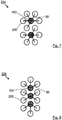
- Fig. 7 shows a second embodiment of the heat exchanger assembly, which is designated here with 22a and is suitable for example for rectangular or oval storage containers. This is different from the one in Fig. 4 shown arrangement in that here two internal heat exchangers 100 are provided, which are each hydraulically connected to five outer heat exchangers 200. Nevertheless, the hexagonal hexagonal honeycomb structure is still present due to the staggered installation of the identical subsystems.
- Fig. 8 shows a further embodiment 22b of the heat exchanger assembly. This is particularly suitable for very stretched container shapes. Here, a hexagonal-like structure is realized, while also the inner heat exchanger 100 are taken into account.
- the entire assembly 22a may be configured such that the individual heat exchangers 100, 200 and associated elements are mechanically interconnected; in such a way that they can float together in the water, if a corresponding ice formation is present.
Abstract
Die vorliegende Erfindung betrifft eine Wärmetauschervorrichtung, die zusammen mit einem Energiespeicher als Teil einer Temperiervorrichtung zum Wärmen und/oder zum Kühlen eines Gebäudes oder eines sonstigen Verbrauchers verwendet werden kann. Dabei wird ein Latentspeicher realisiert, bei dem es zu einer Phasenumwandlung von flüssigem Wasser zu festem Eis kommt. Um die Gefahr der entsprechenden Sprengwirkung zu vermeiden wird eine Kombination aus einem Wärmetauscher erster Bauart und einem Wärmetauscher zweiter Bauart vorgeschlagen. Diese Wärmetauscher weisen erfindungsgemäß eine Leitung mit einem derartigen Verlauf auf, dass jeweils eine Spirale gebildet wird. Außerdem werden sie jeweils von einer Leitung gespeist, die innerhalb dieser Spiralen verlaufen. In einer vorteilhaften Weiterbildung ist es außerdem möglich, dass mittels einer weiteren Wärmetauscheranordnung thermische Energie von einer externen Quelle zugeführt wird, wie von einem Solarkollektor oder dergleichen.The present invention relates to a heat exchanger device which can be used together with an energy storage as part of a temperature control for heating and / or cooling of a building or other consumer. In this case, a latent storage is realized in which there is a phase transformation of liquid water to solid ice. In order to avoid the risk of the corresponding explosive effect, a combination of a heat exchanger of the first type and a heat exchanger of the second type is proposed. According to the invention, these heat exchangers have a conduit with such a course that a spiral is formed in each case. In addition, they are each fed by a line that run within these spirals. In an advantageous development, it is also possible that by means of a further heat exchanger arrangement, thermal energy is supplied from an external source, such as a solar collector or the like.
Description
Die vorliegende Erfindung betrifft eine Wärmetauschervorrichtung für einen Energiespeicher, der als Teil einer Einrichtung zur Temperierung eines Gebäudes oder eines sonstigen Verbrauchers verwendet werden kann. Dabei wird bevorzugterweise ein dichteanomalisches Speichermedium verwendet, wie beispielsweise Wasser.The present invention relates to a heat exchanger device for an energy store, which can be used as part of a device for controlling the temperature of a building or other consumer. In this case, preferably a density-anean storage medium is used, such as water.
Wärmespeicher, die zur Temperierung, also zur Erwärmung und/oder Kühlung von Gebäuden oder anderen Verbrauchern dienen, sind schon lange bekannt. So ist bereits aus der deutschen Offenlegungsschrift
Es ist außerdem bekannt, dass Wärmespeicher besonders effektiv sind, wenn sie als Latentspeicher betrieben werden. Dabei wird der Phasenwechsel eines Speichermediums ausgenutzt - genauer die dabei speicherbare bzw. freigesetzte Energie. So ist aus der deutschen Offenlegungsschrift
Es ist weiterhin bekannt, auch den Phasenwechsel von Wasser als Speichermedium zu nutzen. So offenbart die europäische Offenlegungsschrift
Es ist weiterhin bekannt, dass festes Eis eine geringere Dichte als flüssiges Wasser hat, so dass es bei dem Gefrieren von Wasser zu einer Ausdehnung kommt, die zu einer Sprengwirkung führen kann. Das kann zu Beschädigungen von Dingen führen, die mit dem entstehenden Eis benachbart sind. Dabei kann insbesondere auch ein Behälter beschädigt werden, in dem sich das Speichermedium Wasser bzw. Eis befindet. So beschreibt die europäische Patentschrift
Die in
Es ist die Aufgabe der vorliegenden Erfindung, eine wirkungsvolle Wärmetauschervorrichtung für einen Energiespeicher zu realisieren, die einfach und kostengünstig hergestellt werden kann.It is the object of the present invention to realize an effective heat exchanger device for an energy store, which can be produced easily and inexpensively.
Diese Aufgabe wird gelöst durch die Erfindung nach Anspruch 1. Durch die abhängigen Unteransprüche werden vorteilhafte Weiterentwicklungen angegeben.This object is achieved by the invention according to claim 1. By the dependent subclaims advantageous developments are given.
Die Erfindung hat außerdem den Vorteil, dass Befestigungspunkte vermieden werden können, die die Wärmetauschervorrichtung zur Fixierung mit einem Behälter verbinden. In bekannten Vorrichtungen werden hierzu Befestigungselemente, wie Schrauben oder dergleichen verwendet, die üblicherweise in die Behälterwandung oder in den Behälterboden geschraubt oder sonstwie befestigt werden. Dadurch wird jedoch die Stabilität der Begrenzungsflächen des Speicherbehälters geschwächt. Bei bestimmungsgemäßen Betrieb der bekannten Latentwärmespeicher entstehen an diesen Befestigungspunkten Zugkräfte, welche auf den Speicherbehälter übertragen werden. Außerdem ist in diesen Bereichen durch das eingebrachte Befestigungselement die Reststärke der Wandung reduziert und stellt so einen Schwachpunkt dar.The invention also has the advantage that attachment points can be avoided, which connect the heat exchange device for fixing with a container. In known devices for this purpose fasteners, such as screws or the like are used, which are usually screwed into the container wall or in the container bottom or otherwise secured. As a result, however, the stability of the boundary surfaces of the storage container is weakened. During normal operation of the known latent heat storage arise at these attachment points tensile forces, which are transmitted to the storage tank. In addition, the residual strength of the wall is reduced in these areas by the introduced fastener and thus represents a weak point.
Die erfindungsgemäße Wärmetauschervorrichtung weist zunächst eine erste Wärmetauscheranordnung auf, welche zwei Arten von Wärmetauschern enthält. Diese werden im Folgenden auch Wärmetauscher erster Bauart - oder innerer Wärmetauscher - bzw. Wärmetauscher zweiter Bauart - oder äußerer Wärmetauscher - genannt. Der Wärmetauscher erster Bauart enthält einen ersten Leitungsabschnitt, der spiralförmig verläuft und somit eine Spirale bildet. Der Verlauf dieser Spirale wird bestimmt durch geeignete mechanische Mittel. Diese umfassen bevorzugterweise ein zentrales Standrohr, eine Vielzahl von Außenstützen sowie Querstreben, die das Standrohr und die Außenstützen miteinander verbinden.The heat exchanger device according to the invention initially has a first heat exchanger arrangement, which contains two types of heat exchangers. These are also referred to below as heat exchangers of the first type - or internal heat exchangers - or heat exchangers of the second type - or external heat exchangers. The heat exchanger of the first type comprises a first line section, which runs in a spiral and thus forms a spiral. The course of this spiral is determined by suitable mechanical means. These preferably comprise a central standpipe, a plurality of outer supports and transverse struts connecting the standpipe and the outer supports together.
Der spiralförmig verlaufende Leitungsabschnitt ist an einem ersten Endstück (Zufluss) direkt oder indirekt verbunden mit einer Zuleitung, die somit ein flüssiges, energieärmeres Übertragungsmedium von außen, wie insbesondere von einer Wärmepumpe, in die Spirale einleiten kann. Das andere Endstück (Abfluss) des ersten Leitungsabschnitts ist direkt oder indirekt mit einer Ableitung verbunden, die das durch die Spiralleitung geflossene Übertragungsmedium aufnehmen und direkt oder indirekt weiterleiten kann an ein erstes Endstück (Zufluss) des Wärmetauschers der zweiten Bauart. Dabei verläuft die Zuleitung innerhalb der Spirale des Wärmetauschers erster Bauart - und zwar bevorzugterweise im Wesentlichen parallel zu ihrer Längsachse - und ist mit ihr verbunden an einer Stelle, die sich im betriebsbereiten Zustand am unteren Ende der Spirale befindet. Das zweite Endstück (Abfluss) des Wärmetauschers der zweiten Bauart ist bevorzugterweise direkt oder indirekt verbunden mit der Wärmepumpe.The spirally extending line section is connected to a first end piece (inlet) directly or indirectly connected to a supply line, which can thus introduce a liquid, low-energy transmission medium from the outside, in particular by a heat pump in the spiral. The other end (drain) of the first line section is directly or indirectly connected to a drain which can receive and directly or indirectly pass the transfer medium flowing through the spiral duct to a first end (inflow) of the second type heat exchanger. In this case, the supply line runs within the coil of the heat exchanger of the first type - and preferably substantially parallel to its longitudinal axis - and is connected to it at one Job that is in the ready state at the bottom of the spiral. The second end (drain) of the heat exchanger of the second type is preferably directly or indirectly connected to the heat pump.
Der vorliegenden Erfindung liegt folgende Erkenntnis zugrunde.The present invention is based on the following findings.
Über die Zuleitung fließt das energieärmere Wärmeübertragungsmedium von der Wärmepumpe dem Energiespeicher im Zentrum an dem zentralen Standrohr des Wärmetauschers der ersten Bauart zu und wird im unteren Bereich der Spirale - also quasi im Bereich des Behälterbodens - über die Spirale den Wärmetauschern der zweiten Bauart über die jeweiligen Zuleitungen in gleicher Nähe des Standrohres des inneren Wärmetauschers zugeführt. Hierdurch wird durch die große Oberfläche im Zentrum und die höheren Temperaturdifferenzen zwischen Speichermedium (Wasser oder ähnlich) und dem Wärmeübertragungsmedium (in den Rohren) ein höherer Energiefluss und somit eine stärkere Abkühlung des Speichermediums im Zentrum gewährleistet. Weiterer Energieentzug erfolgt über die Wärmetauscher der zweiten Bauart, die das energiereichere Wärmeübertragungsmedium der Wärmepumpe für den Wärmeprozess wieder zuführen. Kontinuierlicher Energieentzug durch den Wärmepumpenbetrieb reduziert die Kapazität des Speichermediums (Wasser) bzw. entlädt das Speichermedium. Bei ca. 0°C beginnt der Aggregatswechsel des Speichermediums Wasser von flüssig zu fest über die erhöhte Wärmetauscherfläche und die Fließrichtung des energieärmeren Wärmeübertragermediums von der Wärmepumpe kommend im Zentrum des Wärmetauschersystems innerhalb der Spirale des inneren Wärmetauschers an den Zulaufrohren sowie am Beginn der Spirale. Weiterer Energieentzug steigert die Eisbildung und lässt das Eis am Wärmetauscher erster Bauart von innen nach außen und von unten nach oben wachsen. Da erfindungsgemäß bevorzugterweise ein dichteanomalisches Speichermedium, wie beispielsweise Wasser, verwendet wird, bewirkt der feste Aggregatzustand (Eis) einen Auftrieb, der dem Gewicht des Wärmetauschers entgegen wirkt.About the supply line, the lower energy heat transfer medium from the heat pump flows to the energy storage in the center of the central standpipe of the heat exchanger of the first type and is in the lower part of the spiral - that is almost in the container bottom - via the spiral heat exchangers of the second type on the respective Supply lines supplied in the same vicinity of the standpipe of the inner heat exchanger. As a result, the high surface area in the center and the higher temperature differences between the storage medium (water or similar) and the heat transfer medium (in the tubes) ensure a higher energy flow and thus a greater cooling of the storage medium in the center. Further energy extraction takes place via the heat exchanger of the second type, which feed the higher-energy heat transfer medium of the heat pump for the heating process again. Continuous energy extraction by the heat pump operation reduces the capacity of the storage medium (water) or discharges the storage medium. At about 0 ° C, the aggregate change of the storage medium water from liquid to solid begins over the elevated heat exchanger surface and the flow direction of the lower energy heat transfer medium coming from the heat pump in the center of the heat exchanger system within the spiral of the inner heat exchanger at the inlet pipes and at the beginning of the spiral. Further energy extraction increases the formation of ice and allows the ice to grow from the inside to the outside and from bottom to top on the first type of heat exchanger. Since, according to the invention, preferably a density-anemic storage medium, such as water, is used, the solid state (ice) causes a buoyancy which counteracts the weight of the heat exchanger.
Außerdem wirkt weiteres Eiswachstum stabilisierend auf die Anordnung der Wärmetauscherflächen des Wärmetauschers erster Bauart. Ab einem gewissen Betriebspunkt überträgt sich der Energiezustand des Speichermediums auch auf den bzw. die benachbarten bzw. umliegenden Wärmetauscher zweiter Bauart, die bevorzugterweise über ihre flexiblen Zuleitungen von innen nach außen über ihre jeweilige Spirale sowie auch von innen nach außen und von unten nach oben vereisen - bzw. allgemeiner gesagt: das sie umgebende Speichermedium ändert dort seinen Aggregatzustand von flüssig nach fest. Diese Anordnung gewährleistet eine relativ gleichmäßige Temperaturverteilung über das Volumen des Speichermediums des Energiespeichers und vermeidet sicher die zerstörerische Sprengwirkung auf die vorzugsweise zylindrische Umschließungsfläche (Wandung) des Speicherbehälters, in dem sich die Wärmetauscheranordnung bzw. die Wärmetauschervorrichtung befindet.In addition, further ice growth has a stabilizing effect on the arrangement of the heat exchanger surfaces of the heat exchanger of the first design. From a certain Operating point, the energy state of the storage medium is also transferred to the adjacent or surrounding heat exchangers of the second type, which preferably freeze over their flexible leads from the inside to the outside via their respective spiral and also from inside to outside and from bottom to top - or more generally speaking, the surrounding storage medium changes its state of aggregation from liquid to solid. This arrangement ensures a relatively uniform temperature distribution over the volume of the storage medium of the energy storage and safely avoids the destructive explosive effect on the preferably cylindrical enclosure surface (wall) of the storage container in which the heat exchanger assembly or the heat exchanger device is located.
Weitere Eisbildung steigert die Stabilität der Wärmetauscheranordnung und erhöht dessen Auftriebskraft, bis das System innerhalb des Speichermediums (Wasser) zu schweben beginnt und zur Oberfläche aufsteigt und die Wandung des Speicherbehälters über das restliche flüssige Speichermedium vor der Sprengwirkung der weiteren Eisbildung schützt. Durch die Volumenänderung der Eisbildung wird das flüssige Speichermedium teilweise verdrängt. Weiterer Energieentzug lässt den schwebenden, thermisch entladenen Eisblock weiter wachsen, bis die Eintauchtiefe des thermisch entladenen Eisblockes die Höhe des Wasserspiegels überschreitet und der thermisch entladene Eisblock unten aufsetzt, bevorzugterweise auf den Boden eines Behälters, in dem sich Wärmetauscheranordnung befindet.Further ice formation increases the stability of the heat exchanger assembly and increases its buoyancy force until the system begins to float within the storage medium (water) and ascends to the surface, protecting the wall of the storage container from the explosive action of further ice formation over the remaining liquid storage medium. Due to the change in volume of ice formation, the liquid storage medium is partially displaced. Further depletion of energy causes the suspended, thermally-discharged block of ice to continue to grow until the depth of immersion of the thermally-discharged block of ice exceeds the level of the water level and the thermally-discharged block of ice settles at the bottom, preferably at the bottom of a vessel in which the heat exchanger assembly is located.
Für die Realisierung der Erfindung ist es besonders vorteilhaft, ein dichtanomalisches Speichermedium zu verwenden. Obwohl an vielen Stellen der Erfindungsbeschreibung Wasser als derartiges Speichermedium genannt wird, ist die vorliegende Erfindung jedoch keinesfalls auf das Speichermedium Wasser beschränkt. Es kann zusätzlich oder stattdessen auch jedes andere Speichermedium verwendet werden, bei dem während des Übergangs von dem flüssigen in den festen Zustand zumindest anfänglich eine geringere Dichte vorhanden ist.For the realization of the invention it is particularly advantageous to use a density-anomalous storage medium. Although water is referred to as such storage medium in many places of the invention description, however, the present invention is by no means limited to the storage medium water. In addition, or instead, any other storage medium may be used in which, at least initially, a lower density is present during the transition from the liquid to the solid state.
Um die Vereisung im Bereich des Wärmetauschers zweiter Bauart zu verbessern ist es vorteilhaft, dessen Wärmetauscherfläche in seinem Inneren zu erhöhen. Das kann auf verschiedene Weise erfolgen, wie beispielsweise durch die Realisierung einer engeren Spirale, durch spiralenförmige U-Leitungen oder dergleichen. Besonders bewährt hat sich dafür bei einer Weiterbildung der vorliegenden Erfindung die Anordnung von einer oder von mehreren Rohrschlangen innerhalb der Spirale des Wärmetauschers zweiter Bauart, über die das Übertragungsmedium von dem Wärmetauscher der ersten Bauart in die Spirale des Wärmetauschers der zweiten Bauart geleitet wird. Dabei sind die Rohrschlangen bevorzugterweise u-förmig, wobei die U-Schenkel nahezu parallel zu der Längsachse der zugehörigen Spirale verlaufen und die zugehörige U-Wölbung im betriebsbereiten Zustand nach oben zeigt.In order to improve the icing in the region of the heat exchanger of the second type, it is advantageous to increase its heat exchanger surface in its interior. This can be done in various ways, such as by the realization of a narrower spiral, by spiral U-lines or the like. For this purpose, in a further development of the present invention, the arrangement of one or more pipe coils within the spiral of the heat exchanger of the second type, via which the transmission medium is conducted from the heat exchanger of the first type into the spiral of the heat exchanger of the second type, has proved particularly useful. In this case, the coils are preferably U-shaped, wherein the U-legs are almost parallel to the longitudinal axis of the associated spiral and the associated U-buckle in the ready state shows upwards.
Bei einer Weiterentwicklung der Erfindung ist zusätzlich zu der ersten Wärmetauscheranordnung (mit den Wärmetauschern der ersten und der zweiten Bauart) eine weitere Wärmetauscheranordnung vorgesehen. Diese befindet sich während des Betriebes der Energiespeichervorrichtung in thermischen Kontakt zu mindestens einem der übrigen Wärmetauscher, was bevorzugterweise über das Speichermedium (Wasser bzw. Eis) erfolgt. Diese Wärmetauscheranordnung ist bevorzugterweise derart ausgelegt und angeordnet, dass sie dem Speichermedium thermische Energie von einer zweiten thermischen Quelle zuführen kann, wie beispielsweise von einem Solarkollektor/-absorber, einer Wärmepumpe, aus Abwärme von Lüftungsanlagen, Heizkraftwerken, Industrieanlagen und/oder dergleichen.In a further development of the invention, a further heat exchanger arrangement is provided in addition to the first heat exchanger arrangement (with the heat exchangers of the first and the second type). This is during operation of the energy storage device in thermal contact with at least one of the remaining heat exchangers, which preferably takes place via the storage medium (water or ice). This heat exchanger assembly is preferably designed and arranged to supply thermal energy to the storage medium from a second thermal source, such as a solar collector / absorber, a heat pump, waste heat from ventilation systems, heating plants, industrial plants, and / or the like.
Es ist weiterhin besonders vorteilhaft, wenn sich die erste Wärmetauscheranordnung (sowie auch die ggf. vorhandene zweite Wärmetauscheranordnung) in einem Raum - oder auch in einem Behälter mit ggf. eigener Wandung - befindet, der nach unten wasserdicht verschlossen ist und im oberen Bereich einen Überlauf aufweist. Dadurch kann erreicht werden, dass das Speichermedium sich nach oben maximal bis zu dem Überlauf ausdehnen kann. Somit kann auch ein Raum definiert werden, in dem sich kein Speichermedium, sondern stattdessen üblicherweise Luft befindet - ein sogenannter Luftraum.It is furthermore particularly advantageous if the first heat exchanger arrangement (as well as the optionally present second heat exchanger arrangement) is located in a room or in a container with its own wall if necessary, which is sealed watertight downwards and has an overflow in the upper area having. As a result, it can be achieved that the storage medium can expand at the maximum up to the overflow. Thus, a space can be defined in which there is no storage medium, but instead usually air - a so-called airspace.
Die zweite Wärmetauscheranordnung ist bevorzugterweise innerhalb des genannten Raumes ortsfest angeordnet. Es ist jedoch auch möglich, dass sie mechanisch mit der ersten Wärmetauscheranordnung verbunden ist und sich somit auch zusammen mit ihr bewegen kann, wie insbesondere beim Schweben innerhalb des Speichermediums.The second heat exchanger arrangement is preferably arranged stationary within said space. However, it is also possible that it is mechanically connected to the first heat exchanger assembly and thus can also move together with it, such as in particular when floating within the storage medium.
Das Gerüst für die Realisierung der Spiralen kann verschiedene mechanische Elemente enthalten, wie das erwähnte Standrohr, eine Vielzahl von Außenstützen sowie zugehörige Streben. Für die Betriebssicherheit der erfindungsgemäßen Vorrichtung ist es notwendig, dass die Dichte und damit der Auftrieb der ersten Wärmetauscheranordnung dem Speichermedium angepasst werden kann. Das ist beispielsweise möglich, indem in das Innere der genannten Elemente ein Material eingefüllt werden kann, dessen Dichte größer ist als die des flüssigen Speichermediums. Besonders bewährt dafür hat sich Beton, Metall oder ähnliches. Es ist natürlich ebenfalls möglich, dass Beschwerungselemente an anderen Stellen der Wärmetauscheranordnung befestigt werden.The framework for the realization of the spirals may include various mechanical elements, such as the aforementioned standpipe, a plurality of outer supports and associated struts. For the reliability of the device according to the invention, it is necessary that the density and thus the buoyancy of the first heat exchanger assembly can be adapted to the storage medium. This is for example possible by filling into the interior of said elements a material whose density is greater than that of the liquid storage medium. Especially proven is concrete, metal or similar. Of course, it is also possible that weighting elements are attached to other locations of the heat exchanger assembly.
Sofern die erste Wärmetauscheranordnung und die zweite Wärmetauscheranordnung mechanisch miteinander verbunden sind, kann die Dichte der Kombination beider Wärmetauscheranordnungen angepasst werden, indem in das Innere der mechanischen Elemente der ersten Wärmetauscheranordnung und/oder in das Innere von mechanischen Elementen der zweiten Wärmetauscheranordnung ein Material eingefüllt wird, dessen Dichte größer ist als die des flüssigen Speichermediums. Auch bei einer solchen Realisierung ist es natürlich ebenfalls möglich, dass Beschwerungselemente an anderen Stellen der Wärmetauscheranordnungen befestigt werden.If the first heat exchanger arrangement and the second heat exchanger arrangement are mechanically connected to one another, the density of the combination of the two heat exchanger arrangements can be adapted by filling a material into the interior of the mechanical elements of the first heat exchanger arrangement and / or into the interior of mechanical elements of the second heat exchanger arrangement, whose density is greater than that of the liquid storage medium. Of course, even with such an implementation, it is also possible that weighting elements are attached to other locations of the heat exchanger assemblies.
Weitere Einzelheiten und Vorteile der vorliegenden Erfindung werden im Folgenden anhand von bevorzugten Ausführungsbeispielen mit zugehörigen Abbildungen erläutert. Dabei zeigen:
- Fig. 1
- eine Einrichtung zur Temperierung
- Fig. 2
- seitliche Querschnittsdarstellung eines bevorzugten Wärmespeichers
- Fig. 3
- symbolische Darstellung einer Doppelhelix
- Fig. 4
- Draufsicht auf den Wärmespeicher
- Fig. 5
- vereinfachte Querschnittsdarstellung des Wärmespeichers ohne Vereisung
- Fig. 6
- vereinfachte Querschnittsdarstellung des Wärmespeichers mit Vereisung
- Fig. 7
- symbolische Darstellung eines ersten erweiterten Wärmetauschersystems
- Fig. 8
- symbolische Darstellung eines zweiten erweiterten Wärmetauschersystems
- Fig. 1
- a device for temperature control
- Fig. 2
- lateral cross-sectional view of a preferred heat storage
- Fig. 3
- symbolic representation of a double helix
- Fig. 4
- Top view of the heat storage
- Fig. 5
- simplified cross-section of the heat accumulator without icing
- Fig. 6
- simplified cross-section of the heat accumulator with icing
- Fig. 7
- symbolic representation of a first extended heat exchanger system
- Fig. 8
- symbolic representation of a second extended heat exchanger system
In
In dem Wärmespeicher-Behälter 11 befindet sich bei der bevorzugten Ausführung eine zweite Wärmetauscheranordnung 30. Diese ist über ein weiteres Leitungssystem 32 mit einer thermischen Quelle 34 verbunden. Eine solche thermische Quelle 34 kann auf vielfältige Weise realisiert sein. In dem bevorzugten Ausführungsbeispiel ist die thermische Quelle 34 eine regenerative Quelle wie z.B. ein Absorber oder insbesondere ein Solarkollektor. Daher wird die zweite Wärmetauscheranordnung im Folgenden als Solar-Wärmetauscheranordnung 30 bezeichnet.In the
Der Solarkollektor 34 ist derart ausgebildet, dass er ein geeignetes Übertragungsmedium, wie ein Gemisch aus Wasser und Frostschutzmittel, erwärmt. Dieses Übertragungsmittel wird über das Leitungssystem 32 der Solar-Wärmetauscheranordnung 30 zugeführt, die sich innerhalb des Speichermediums Wassers 14 befindet und die dem Speichermedium 14 entnommene Energiemenge wieder zuführt bzw. dieses entsprechend erwärmt.The
Der Vollständigkeit halber sei erwähnt, dass in den Leitungssystemen 24, 28, 32 noch weitere Mittel enthalten sind, wie Pumpen, verschiedene Ventile, Anschlussverbindungen und dergleichen. Da diese nicht erfindungswesentlich sind, sind sie hier aus Gründen der Übersichtlichkeit nicht dargestellt.For the sake of completeness it should be mentioned that in the
Die in
Der in
Mit der mechanischen Struktur ist eine Schlauchleitung verbunden, deren Verlauf sich in verschiedene Abschnitte unterteilen lässt, nämlich
eine Spirale 108 mit einem unteren Endstück 114 (Zufluss) und einem oberen Endstück 109 (Abfluss). Die Spirale kann auch als Doppelhelix ausgebildet sein (s.Fig. 3 )- eine nahezu senkrecht nach
unten verlaufende Zuleitung 110, anderen Eingang 112 die Wärmetauscher-Zuleitung 25 angeschlossen ist und an deren Ausgangdas untere Endstück 114der Spirale 108 angeschlossen ist ein Verteilerelement 116, das mitdem oberen Endstück 109der Spirale 108 verbunden ist und die aus derSpirale 108 fließende Wärmeübertragungsflüssigkeit an vorzugsweise sechs Ableitungen 118 abgeben kann, in die hier jeweilsein Ventil 117 angeordnet ist- zwei dieser Ableitungen 118 -
mit 118a bzw. 118b markiert - dienen zum Anschluss der beiden inFig. 2 gezeigten äußeren Wärmetauscher 200. Die Ausgänge der Ableitungen 118a bzw. 118b führen jeweils innerhalb der Spirale des inneren Wärmetauschers 100 zu einer vorzugsweise flexiblen Verbindungsleitung 50a bzw. 50b, an die jeweils einer der äußeren Wärmetauscher 200 angeschlossen ist.
Hierzu sei angemerkt, dass die Anzahl der tatsächlichen - nicht der hier gezeigten -Ableitungen 118 üblicherweise direkt abhängig ist von der Anzahl der anden inneren Wärmetauscher 100 angeschlossenen äußeren Wärmetauscher 200. Daher sind üblicherweise mehr als zwei derAbleitungen 118 und der zugehörigen Verbindungsleitungen 50 vorhanden.
- a
scroll 108 having a lower end portion 114 (inflow) and an upper end portion 109 (outflow). The spiral can also be designed as a double helix (s.Fig. 3 ) - a nearly vertically downwardly extending
supply line 110, at theinput 112, the heatexchanger feed line 25 is connected and at the output of thelower end portion 114 of thespiral 108 is connected - a
distributor element 116, which is connected to theupper end portion 109 of thespiral 108 and which can deliver heat transfer fluid flowing from thespiral 108 to, preferably, sixoutlets 118 into which arespective valve 117 is arranged - two of these leads 118 - marked 118a and 118b respectively - are used to connect the two in
Fig. 2 The outlets of theoutlets inner heat exchanger 100 to a preferably flexibleConnecting line outer heat exchanger 200 is connected.
It should be noted here that the number of actual outlets 118 - not shown here - usually depends directly on the number ofouter heat exchangers 200 connected to theinner heat exchanger 100. Therefore, more than two of theoutlets 118 and the associatedconnection lines 50 are usually present ,
Die Verbindungen zwischen der Zuleitung 110 und der Spirale 108 bei dem unteren Endstück 114 können auf verschiedene Weisen realisiert sein, wie beispielsweise durch eine durchgängige Leitung (bzw. einen durchgängigen Schlauch), die ohne zwischengeschaltete Mittel direkt von der Zuleitung 110 in die Spirale 108 übergeht. Denkbar ist jedoch auch, dass an dem Endstück 114 Verbindungselemente vorgesehen sind, die hier nicht dargestellt und dem Fachmann allgemein bekannt sind. Das gleiche gilt auch für den Übergang an dem oberen Endstück 109 der Spirale 108.The connections between the lead 110 and the
Mit der mechanischen Struktur ist eine Schlauchleitung verbunden, deren Verlauf sich in verschiedene Abschnitte unterteilen lässt, nämlich
eine Spirale 208 mit einem unteren Endstück 214 (Zufluss) und einem oberen Endstück 216 (Abfluss),- eine erste u-förmige Rohrschlange 210, deren U-Schenkel im Wesentlichen senkrecht, das heißt im Wesentlichen parallel zu der Längsachse der
Spirale 208, verlaufen und deren erster Anschluss 201 (Zufluss) über eine der Verbindungsleitungen 50 -hier konkret 50a bzw. 50b -mit den Ableitungen 118a bzw. 118b desVerteilerelementes 116 verbunden ist und die in eine zweite u-förmige Rohrschlange 212 mündet, deren U-Schenkel ebenfalls im Wesentlichen senkrecht, das heißt im Wesentlichen parallel zur Längsachse derSpirale 208, verlaufen, wobei - der Ausgang der zweiten Rohrschlange 212 mit
dem unteren Endstück 214der Spirale 208 verbunden ist.
- a
spiral 208 having a lower end 214 (inflow) and an upper end 216 (outflow), - a first
U-shaped tube coil 210, the U-legs of which extend essentially perpendicularly, that is to say essentially parallel to the longitudinal axis of thespiral 208, and whose first connection 201 (inflow) extends via one of the connecting lines 50 - here specifically 50a or 50b - is connected to theoutlets distribution element 116 and which opens into a secondU-shaped tube 212, the U-legs also substantially perpendicular, that is substantially parallel to the longitudinal axis of thespiral 208, extend - the output of the
second coil 212 is connected to thelower end 214 of thecoil 208.
Die Rohrschlangen 210, 212 weisen ihren Bogen am oberen Ende auf und haben bevorzugterweise eine gleiche Höhe h. Jedoch können sie auch unterschiedlich hoch sein. Die Gesamthöhe H der Wärmetauscher 100, 200 ist abhängig von der Wassertiefe, also von dem Abstand der Wasseroberfläche 16 - entspricht üblicherweise der Unterkante von Ablauf 20 - von dem inneren Boden der Wandung 12. Bei einer Wassertiefe von etwa 2 Metern hat sich eine Wärmetauscher-Höhe H von ca. 1,85 Meter bewährt. Die Höhe h der Rohrschlangen 210, 212 sollte geringer sein als die Höhe H der sie umschließenden Spirale 208. Dadurch kann die Betriebssicherheit der Einrichtung erhöht werden, da Lufteinschlüsse vermindert bzw. durch den Strom des Wärmeträgermediums und des geodätischen Höhenunterschiedes mitgerissen und so verhindert werden können. Für das Verhältnis der beiden Werte h und H zueinander hat sich besonders bewährt: ![]()
![]()
Das obere Endstück 216 der Spirale 208 des äußeren Wärmetauschers 200 ist deren Abfluss und führt über eine Ableitung 211 und ein Ventil 217 zu einem Eingang eines weiteren Sammlerelements bzw. Verteilerelements 218. Weitere Eingänge dieses Verteilerelements 218 sind mit entsprechenden Leitungen der anderen äußeren Wärmetauscher 200 verbunden. Der Ausgang dieses Verteilerelements 218 ist über geeignete Mittel an die Wärmetauscher-Rückleitung 26 (s.a.
Wie in
Für das bevorzugte Ausführungsbeispiel hat sich sowohl für den inneren Wärmetauscher 100 als auch für die äußeren Wärmetauscher 200 jeweils ein Rohr aus hochwertigem Polyethylen - auch PE Rohr genannt - mit einem Außendurchmesser von 25 mm und einer Wandstärke von ca. 2 mm insbesondere aus Kostengründen besonders bewährt. Denkbar sind jedoch auch Ausführungen mit anderen Rohrmaterialien, wie beispielsweise aus Metall, wie insbesondere Kupfer. Bei hohen Leistungsanforderungen sind außerdem andere Abmessungen bzw. Dimensionen sinnvoll oder notwendig.For the preferred embodiment, both for the
Die jeweilige Schlauchleitung von 100 bzw. 200 kann auch aus einer Vielzahl von einzelnen Elementen bestehen, die miteinander auf geeignete Weise verbunden sind. Es ist außerdem möglich, dass zumindest einzelne der oben genannten Abschnitte aus einem anderen Material bestehen, wie beispielsweise Kupfer oder dergleichen. Verbindungselemente, die die Schlauchleitung an der mechanischen Struktur fixieren und/oder einzelne Abschnitte der Schlauchleitung miteinander verbinden, sind in der Zeichnung aus Gründen der Übersichtlichkeit nicht dargestellt.The respective tubing of 100 and 200 may also consist of a plurality of individual elements, which are connected together in a suitable manner. It is also possible that at least some of the above-mentioned sections are made of a different material, such as copper or the like. Fasteners which fix the hose to the mechanical structure and / or interconnect individual sections of the hose are not shown in the drawing for reasons of clarity.
Es hat sich besonders gut bewährt, wenn der innere Wärmetauscher 100 anstelle einer einzigen Spirale 108 zwei Spiralleitungen aufweist, die quasi eine Doppelhelix bilden. Eine bevorzugte Ausbildung dafür ist symbolisch in
Bei der zugehörigen bevorzugten Ausführung wird die Zuleitung 25 vor Eintritt in den inneren Wärmetauscher 100 aufgeteilt in die Zuleitungen 110a, 110b, die innerhalb der Helix 108a, 108b nahezu senkrecht nach unten verlaufen. An zugehörigen Abflüssen 114a, 114b werden sie der zugehörigen Spirale 108a, 108b zugeführt. Die oberen Endstücke 109a, 109b können gemeinsam über Anschluss 109 mit dem Verteilerelement 116 verbunden sein. Es ist jedoch auch möglich, dass jede der Spiralen 108a, 108b mit einem eigenen Verteilerelement 116a, 116b (in den Figuren nicht gezeigt) verbunden ist, deren Ausgänge anteilig die zugehörigen äußeren Wärmetauscher 200 versorgen.In the associated preferred embodiment, the
Es hat sich bewährt, dass die Zuleitung 25 und der Abfluss 109 einen größeren Schlauchdurchmesser aufweisen (z.B. PE 32 Schlauch) als die übrigen Elemente 108a, 108b, 110a, 110b (z.B. jeweils PE 25 Schlauch).It has been proven that the
Bei anderen Behälterformen oder Behältergrößen sind zur optimalen Ausnutzung des Speichermediums 14 auch andere Kombinationen der Wärmetauscherelemente 100 und 200 möglich, welche vom Solarwärmetauscher 30 umschlossen werden bzw. bei Kaskadierung der Wärmetauscheranordnung 22, die entweder einzeln für sich quasi als Zelle mit einem Solarwärmetauscher oder insgesamt in der Summe mit nur einem Solarwärmetauscher umschlossen sind. Hierzu sei erwähnt, dass die Energiezufuhr zum Speicher 11 auch durch Abwärme aus technischen Prozessen, durch überschüssige Wärme aus dem Gebäude oder dessen technischen Geräte erfolgen kann. Die erforderliche Energieabfuhr und Einspeicherung von Energie durch Übertragung auf das Speichermedium 14 bestimmen die Art und Anordnung des Solarwärmetauschers.In other container shapes or container sizes, other combinations of the
Die Abflüsse 216 der Spiralen 208 der äußeren Wärmetauscher 200 führen zu dem Sammlerelement 218, welches hier ebenfalls nicht dargestellt ist.The
Der innere Wärmetauscher 100 und die äußeren Wärmetauscher 200 sind miteinander mechanisch durch geeignete Verbindungselemente 302, 304, wie Streben und dergleichen verbunden. Diese dienen unter anderem als Abstandshalter und bewirken eine im Wesentlichen starre Verbindung, so dass die Struktur der Wärmetauscheranordnung 22 auch bei Bewegungen, wie insbesondere beim Schweben in einer Flüssigkeit, vollständig oder zumindest annähernd erhalten bleibt.The
Anhand der
In den
Das Gewicht und somit die Dichte der Wärmetauscheranordnung 22 kann auf verschiedene Weisen verändert werden. Es hat sich besonders bewährt, dass die zentralen Standrohre 102 und/oder 202 zumindest teilweise mit Material gefüllt sind, das schwerer ist als das Wasser 14, wie beispielsweise mit Beton. Dadurch kann erreicht werden, dass die Anordnung 22 einerseits bei flüssigem Zustand des Wassers 14 betriebssicher auf den Boden aufsetzt und andererseits bei bestimmter Menge von Eisbildung (s.a.
Der in Behälter 11 vorhandene Wärmespeicher ist zusammen mit der Wärmepumpe 27 derart ausgelegt, dass er als Latentwärmespeicher arbeiten kann und somit die latente Energie bei der Phasenumwandlung von flüssigem Wasser zu Eis ausnutzen kann. Das bedeutet, dass der Wärmespeicher auch in einen Betriebszustand kommen kann, in dem sich Eis innerhalb des Speichermediums Wasser 14 bildet. Ein solcher Betriebszustand ist in
In
Das Wachstum des Eises beginnt aufgrund der erfindungsgemäßen Anordnung zunächst im Bereich des inneren Wärmetauschers 100 und erfolgt recht langsam bevor sich das Eiswachstum auf die äußeren Wärmetauscher 200 überträgt. Dadurch können Lufteinschlüsse im Eis vermieden werden, was die mechanische Stabilität entsprechend erhöht.Due to the arrangement according to the invention, the growth of the ice first begins in the region of the
Aufgrund der angeordneten Rohrschlangen 210, 212 erfolgt die Eisbildung bei den äußeren Wärmetauschern ebenfalls von innen heraus.Due to the arranged tube coils 210, 212, the ice formation in the outer heat exchangers also takes place from the inside out.
Somit lässt sich der Betrieb der bevorzugten Einrichtung zur Temperierung also auch folgendermaßen beschreiben:Thus, the operation of the preferred means for temperature control can thus also be described as follows:
Über das Zulaufrohr 25 fließt das energieärmere Wärmeübertragermedium der Wärmepumpe 27 dem Wärmespeicher im Zentrum an dem zentralen Standrohr 102 des inneren Wärmetauschers 100 zu und wird am Behälterboden über die Helix 108 und dem Verteilerelement 116 den äußeren, umliegenden Wärmetauschern 200 über die jeweiligen Leitungen 118 und 50 in gleicher Nähe des Standrohres 102 des inneren Wärmetauschers 100 zugeführt. Hierdurch wird durch die große Wärmeübertragungsfläche im Zentrum des Speichers und die höheren Temperaturdifferenzen zwischen Speichermedium 14 und Wärmeübertragermedium (in der Schlauchleitung) ein höherer Energiefluss und somit eine stärkere Abkühlung des Speichermediums 14 im Zentrum gewährleistet.Via the
Die aus der Leitungsdichte der Spirale 108 (bzw. Mehrfach-Helix) resultierende Wärmeübertragungsfläche sichert im Bereich des inneren Wärmetauschers 100 eine hohe Übertragungsleistung bzw. bedingt durch den Eintritt der energiearmen Wärmeträgerflüssigkeit im Zentrum eine höhere Abkühlung des Speichermediums Wasser 14 als im äußeren Bereich der in Fließrichtung der Wärmeträgerflüssigkeit nachfolgenden äußeren Wärmetauscher 200.The heat transfer surface resulting from the line density of the spiral 108 (or multiple helix) secures in the area of the inner heat exchanger 100 a high transmission power or due to the entry of the low-energy heat transfer fluid in the center, a higher cooling of the
Weiterer Energieentzug erfolgt über die äußeren Wärmetauscher 200, die über das Sammlerelement 218 das energiereichere Wärmeübertragermedium der Wärmepumpe 27 für den Wärmepumpenkreisprozess wieder zuführen. Kontinuierlicher Wärmepumpenbetrieb reduziert die Kapazität des Speichermediums Wasser bzw. entlädt das Speichermedium und bei ca. 0°C beginnt der Aggregatswechsel des Speichermediums Wasser von flüssig zu fest über die erhöhte Wärmetauscherfläche und das energieärmere Wärmeübertragermedium am inneren Wärmtauscher 100 innerhalb der Spirale 108 an den Zulaufrohren sowie am Zufluss 114 der Spirale 108. Weiterer Energieentzug steigert die Eisbildung und lässt das Eis am inneren Wärmetauscher 100 von innen nach außen und von unten nach oben wachsen. Dem Auftrieb des Eises wirkt das Gewicht des zentralen Standrohrs 102 sowie daran befestigter Elemente entgegen. Weiteres Eiswachstum wirkt stabilisierend auf die Anordnung der Wärmetauscherflächen des inneren Wärmetauschers 100.Further energy removal takes place via the
Ab einem gewissen Betriebspunkt überträgt sich der Energiezustand des Speichermediums Wasser 14 auch auf die umliegenden äußeren Wärmetauscher 200, die in dem Beispiel über die Zuleitungen 118 und die flexiblen Wärmetauscher-Verbindungsleitungen 50 von innen über die Wärmtauscherschlangen 210, 212 nach außen über ihre jeweilige Spirale 208 auch von innen nach außen und von unten nach oben vereisen.From a certain operating point, the energy state of the
Die aus der Leitungsdichte im unteren Teil des äußeren Wärmetauschers 200 resultierende Wärmeübertragungsfläche sichert in dessen unteren Bereich eine höhere Übertragungsleistung bzw. bedingt durch den Eintritt der energieärmeren Wärmeträgerflüssigkeit im Zentrum eine höhere Abkühlung des Speichermediums 14 als im oberen Bereich der in Fließrichtung der Wärmeträgerflüssigkeit nachfolgenden oberen Teil der Helix 208 des äußeren Wärmetauscher 200, deren Wicklungsdichte zur Oberfläche des Speichermediums ab dem Wendepunkt der senkrecht verlaufenden Rohrschlangen 210, 212 abnimmt bzw. in Abhängigkeit der benötigten Entzugsleistung abnehmen kann.The resulting from the line density in the lower part of the
Diese Anordnung gewährleistet eine relativ gleichmäßige Temperaturverteilung über das Volumen des Speichermediums 14 der Wärmetauscheranordnung 22 bzw. des Energiespeichers und vermeidet sicher die zerstörerische Sprengwirkung auf die vorzugsweise zylindrische Wandung 12 (Umschließungsfläche) des Wärmespeicher-Behälters 11. Weitere Eisbildung steigert die Stabilität der Wärmetauscheranordnung 22 und erhöht deren Auftriebskraft, bis die Wärmetauscheranordnung 22 zu Schweben beginnt und zur Oberfläche 16 aufsteigt. Die Wandung 12 des Behälters 11 wird über das restliche flüssige Speichermedium 14 vor der Sprengwirkung der weiteren Eisbildung geschützt. Weiterer Energieentzug steigert das Eiswachstum. Durch die Volumenänderung der Eisbildung wird das flüssige Speichermedium 14 teilweise verdrängt und der thermisch entladene Eisblock setzt auf den Behälterboden auf bevor der komplette Eisblock die umfassende Behälterwandung 12 erreicht hat.This arrangement ensures a relatively uniform temperature distribution over the volume of the
Bei einer weiteren Ausführungsform ist vorgesehen, dass die zweite Wärmetauscheranordnung 30 nicht fest an der Wandung 12 montiert ist, sondern mechanisch mit der ersten Wärmeaustauscheranordnung 22 verbunden ist, so dass sich die beiden Anordnungen 22 und 30 gemeinsam bewegen können. In einem solchen Fall bewirkt die Eisbildung, dass das gesamte Wärmetauschersystem - bestehend aus der Wärmetauscheranordnung 22 und dem Solarwärmetauscheranordnung 30 - in Abhängigkeit vom Fortschritt der Eisbildung stabilisiert wird und auch eine erhöhte Auftriebskraft erfährt, so dass es bei ausreichender Eisbildung zu schweben beginnen kann. Im Falle einer mechanischen Verbindung beider Wärmetauscheranordnungen 22 und 30 kann außerdem die Dichte dieses Wärmetauschersystems verändert werden, indem in das Innere der mechanischen Elemente 102, 202 der ersten Wärmetauscheranordnung 22 und/oder in das Innere von mechanischen Elementen der zweiten Wärmetauscheranordnung 30 ein Material eingefüllt wird, dessen Dichte größer ist als die des flüssigen Speichermediums Wasser 14.In a further embodiment it is provided that the second
Die gesamte Anordnung 22a kann derart gestaltet sein, dass die einzelnen Wärmetauscher 100, 200 und die zugehörigen Elemente mechanisch miteinander verbunden sind; und zwar derart, dass sie gemeinsam in dem Wasser schweben können, wenn eine entsprechende Eisbildung vorhanden ist.The
Es sei darauf hingewiesen, dass das beschriebene bevorzugte Ausführungsbeispiel mit seinen genannten Abwandlungen nur beispielhaft ist für die Realisierung der vorliegenden Erfindung. Es sind vielfältige Abwandlungen bzw. Ergänzungen möglich wie beispielsweise:
- Bei warmen Außentemperaturen, wie beispielsweise im Sommer, kann die Einrichtung zur Temperierung auch zum Kühlen eines Verbrauchers - wie dem Gebäude 10 - eingesetzt werden, indem die entsprechende Wärmeenergie
von dem Verbraucher 10 in dem Wärmespeicher eingespeichert wird. Dazu kann nach Abschluss des Schmelzprozesses durch die passive Kühlung des Gebäudes 10 durch den Wärmespeicher zur weiterenKühlung die Wärmepumpe 27 entsprechend aktiv betrieben werden. Dazu sind entsprechende Ventile vorzusehen. Diese sind zwar in den Figuren nicht gezeigt, jedoch dem Fachmann allgemein bekannt, wie beispielsweise aus der SchriftEP 1 807 672 B1 - Zusätzlich oder anstelle des Solarkollektors 34 können auch andere thermische Quellen verwendet werden, wie beispielsweise
- ein Absorber,
- eine Wärmepumpe,
- Mittel, die Abwärme aufnehmen aus Lüftungsanlagen, Niederschlag, Abluftanlagen, Blockheizkraftwerken und/oder dergleichen,
- Mittel, die überschüssige Wärme des Gebäudes 10 (oder eines sonstigen Verbrauchers) in den warmen Jahreszeiten aufnehmen (passive Kühlung),
- Die
Anzahl der Außenstützen 104 und/oder 204 kann größer oder kleiner als vier sein. Es gilt allgemein, dass eine ausreichende Anzahl derAußenstützen Wärmetauscher - Mehrere innere Wärmetauscher 100 können gemeinsam
von äußeren Wärmetauschern 200 umgeben sein. - In Abhängigkeit von Behältergröße und -form sind auch andere Anordnungen der inneren Wärmetauscher 100 und der äußeren Wärmetauscher 200 möglich bzw. wegen der bevorzugten hexagonalen Anordnung auch die Kaskadierung des
Wärmetauschersystems 22. - Bei Verwendung der Doppelhelix innerhalb des
Wärmetauschers 100 ist es auch möglich, dass jede der beiden Spiralen jeweils anteilig die Hälfte (also drei oder dergleichen) der äußeren Wärmetauscher 200 versorgt. Dafür sind entsprechende Anschlusselemente vorzusehen, die dem Fachmann jedoch allgemein bekannt sind. - Der innere Wärmetauscher 100 kann auch derart gestaltet sein, dass zusätzlich oder anstelle der Spirale oder der Doppelhelix eine Mehrfach-Helix vorgesehen ist.
- Zumindest einer der äußeren Wärmetauscher 200 kann derart gestaltet sein, dass anstelle oder zusätzlich zu der
Spirale 208 eine Doppelhelix und/oder eine Mehrfach-Helix vorgesehen ist. Die zugehörigen Anschlüsse können ähnlich vorgesehen sein, wie im Zusammenhang mitdem inneren Wärmetauscher 100 erläutert.
- At warm outdoor temperatures, such as in summer, the device for temperature control for cooling a consumer - such as the building 10 - are used by the corresponding heat energy is stored by the
consumer 10 in the heat storage. For this purpose, after completion of the melting process by the passive cooling of thebuilding 10 through the heat storage for further cooling, theheat pump 27 can be actively operated accordingly. For this purpose, appropriate valves must be provided. These are not in the figures shown, but well known to those skilled in the art, such as from the ScripturesEP 1 807 672 B1 - In addition to or instead of the
solar collector 34, other thermal sources may be used, such as- an absorber,
- a heat pump,
- Means which absorb waste heat from ventilation systems, precipitation, exhaust air systems, combined heat and power plants and / or the like,
- Means to absorb the excess heat of the building 10 (or other consumer) in the warm seasons (passive cooling),
- The number of
outer supports 104 and / or 204 may be greater or less than four. It is general that a sufficient number ofouter supports heat exchangers - A plurality of
internal heat exchangers 100 may be shared byexternal heat exchangers 200. - Depending on the container size and shape, other arrangements of the
inner heat exchanger 100 and theouter heat exchanger 200 are also possible or, because of the preferred hexagonal arrangement, also the cascading of theheat exchanger system 22. - When using the double helix within the
heat exchanger 100, it is also possible that each of the two spirals in each case proportionally supplies half (ie three or the like) of theouter heat exchanger 200. For this purpose, appropriate connection elements are provided which are, however, generally known to the person skilled in the art. - The
inner heat exchanger 100 may also be designed such that in addition to or instead of the spiral or the double helix a multiple helix is provided. - At least one of the
outer heat exchangers 200 may be configured such that instead of or in addition to thespiral 208, a double helix and / or a Multiple helix is provided. The associated ports may be similarly provided as explained in connection with theinner heat exchanger 100.
- 1010
- Gebäudebuilding
- 1111
- Behälter für Energiespeicher (auch Wärmespeicher genannt)Container for energy storage (also called heat storage)
- 1212
- Wandung von 11Wall of 11
- 1313
- Erdoberflächeearth's surface
- 1414
- Wasserwater
- 1616
- Wasseroberflächewater surface
- 1818
- Luftraumairspace
- 2020
- Überlaufoverflow
- 2222
- erste Wärmetauscheranordnungfirst heat exchanger arrangement
- 2424
- erstes Leitungssystemfirst line system
- 2525
- Wärmetauscher-ZuleitungHeat exchanger supply line
- 25, b25, b
- erste bzw. zweite Teilzuleitungfirst or second partial supply line
- 2626
- Wärmetauscher-RückleitungHeat exchanger return line
- 2727
- Wärmepumpeheat pump
- 2828
- zweites Leitungssystemsecond pipe system
- 3030
- Solar-WärmetauscheranordnungSolar heat exchanger assembly
- 3232
- Leitungssystem zu 34Line system to 34
- 3434
- Solarkollektorsolar collector
- 50; 50a, b50; 50a, b
- Wärmetauscher-VerbindungsleitungenHeat exchanger interconnectors
- 100100
- innerer Wärmetauscherinternal heat exchanger
- 102102
- zentrales Standrohr von 100central standpipe of 100
- 104104
- Außenstützen von 100External supports of 100
- 106106
- Querstreben von 100Cross struts of 100
- 108108
- Spirale von 100Spiral of 100
- 108a, b108a, b
- Spiralen einer DoppelhelixSpirals of a double helix
- 109109
- oberes Endstück von 108 (Abfluss)upper tail of 108 (outflow)
- 110110
- Zuleitung von 108Supply line of 108
- 110a, b110a, b
- Zuleitungen einer DoppelhelixSupply lines of a double helix
- 111111
- Ableitung von 108Derivation of 108
- 112112
- Zufluss von 110Inflow of 110
- 114114
- unteres Endstück von 108 (Zufluss)lower tail of 108 (inflow)
- 116116
- Verteilerelementdistributor element
- 117117
- Ventilevalves
- 118118
- Ableitungen von 116Derivatives of 116
- 120120
- mittlere Eisablagerungmedium ice deposit
- 200200
- äußerer Wärmetauscherouter heat exchanger
- 201201
- erster Anschluss von 210 (Zufluss)first connection of 210 (inflow)
- 202202
- zentrales Standrohr von 200central standpipe of 200
- 204204
- Außenstützen von 200External supports of 200
- 206206
- Querstreben von 200Cross struts of 200
- 208208
- Spirale von 200Spiral of 200
- 210210
- erste Rohrschlangefirst pipe coil
- 211211
- Ableitung von 208Derivation of 208
- 212212
- zweite Rohrschlangesecond pipe coil
- 214214
- unteres Endstück von 208 (Zufluss)lower tail of 208 (inflow)
- 216216
- oberes Endstück von 208 (Abfluss)upper tail of 208 (outflow)
- 217217
- Ventilevalves
- 218218
- Sammlerelementcollectors item
- 220220
- äußere Eisablagerungouter ice deposit
- 302, 304302, 304
- mechanische Verbindungselementemechanical fasteners
Claims (17)
Applications Claiming Priority (1)
| Application Number | Priority Date | Filing Date | Title |
|---|---|---|---|
| DE102016000176.3A DE102016000176A1 (en) | 2016-01-13 | 2016-01-13 | heat exchanger device |
Publications (2)
| Publication Number | Publication Date |
|---|---|
| EP3193117A1 true EP3193117A1 (en) | 2017-07-19 |
| EP3193117B1 EP3193117B1 (en) | 2019-02-27 |
Family
ID=57794112
Family Applications (1)
| Application Number | Title | Priority Date | Filing Date |
|---|---|---|---|
| EP17000035.0A Active EP3193117B1 (en) | 2016-01-13 | 2017-01-10 | Heat exchange device |
Country Status (2)
| Country | Link |
|---|---|
| EP (1) | EP3193117B1 (en) |
| DE (1) | DE102016000176A1 (en) |
Cited By (5)
| Publication number | Priority date | Publication date | Assignee | Title |
|---|---|---|---|---|
| CN107466188A (en) * | 2017-08-16 | 2017-12-12 | 中国原子能科学研究院 | A kind of cooling medium transport structure on high potential xegregating unit |
| WO2022026499A1 (en) * | 2020-07-28 | 2022-02-03 | Alliance For Sustainable Energy, Llc | Methods and systems for thermal energy storage and their use in buildings applications |
| CN114440681A (en) * | 2020-11-05 | 2022-05-06 | 中国石油化工股份有限公司 | Phase-change heat storage device and heat storage method thereof |
| IT202100001091A1 (en) * | 2021-01-22 | 2022-07-22 | I Tes S R L | LATENT HEAT THERMAL STORAGE BATTERY |
| CN114992694A (en) * | 2022-05-18 | 2022-09-02 | 叶卫东 | Water or ice storage tank |
Families Citing this family (1)
| Publication number | Priority date | Publication date | Assignee | Title |
|---|---|---|---|---|
| US11680754B2 (en) | 2021-04-09 | 2023-06-20 | Trane International Inc. | Systems and methods for thermal storage solid phase formation removal |
Citations (6)
| Publication number | Priority date | Publication date | Assignee | Title |
|---|---|---|---|---|
| DE2803458A1 (en) | 1978-01-27 | 1979-08-02 | Uwe Hansen | Solar heating system combined with underground heat store - has underground coil connected with heat pump and are enclosed by earth core |
| EP0031942A1 (en) | 1979-12-28 | 1981-07-15 | CHEMOWERK GmbH Fabrik für Behälter und Transportgeräte | Method of operating a heating device for the exploitation of terrestrial heat with a heat pump together with apparatus for carrying out the method |
| DE3224854A1 (en) | 1982-07-02 | 1984-01-05 | Corbelia GmbH, 5412 Puch | Heat store |
| EP1807672B1 (en) | 2004-10-26 | 2008-10-01 | von Rohr Alex | Energy accumulator, heat exchanger system for an energy accumulator, energy storage system and corresponding method |
| DE202010015153U1 (en) * | 2009-11-05 | 2011-03-31 | Yang, Tai-Her, Si-Hu Town | Standing in a natural heat body standing fluid heat exchanger |
| EP2503251A2 (en) * | 2011-03-21 | 2012-09-26 | Robert Egg | Storage heat exchanger device |
Family Cites Families (3)
| Publication number | Priority date | Publication date | Assignee | Title |
|---|---|---|---|---|
| NL7204070A (en) * | 1972-03-27 | 1973-10-01 | ||
| DE202010000027U1 (en) * | 2009-03-24 | 2010-03-25 | Latherm Gmbh | Latent heat storage |
| DE102012001085A1 (en) * | 2012-01-20 | 2013-07-25 | Efficient Home Energy, S.L. | Device for heating processing water in residential building, has guiding devices for enclosing pipeline and causing separated flow of storage water to lower area of container, where guiding devices are arranged parallel to each other |
-
2016
- 2016-01-13 DE DE102016000176.3A patent/DE102016000176A1/en active Pending
-
2017
- 2017-01-10 EP EP17000035.0A patent/EP3193117B1/en active Active
Patent Citations (6)
| Publication number | Priority date | Publication date | Assignee | Title |
|---|---|---|---|---|
| DE2803458A1 (en) | 1978-01-27 | 1979-08-02 | Uwe Hansen | Solar heating system combined with underground heat store - has underground coil connected with heat pump and are enclosed by earth core |
| EP0031942A1 (en) | 1979-12-28 | 1981-07-15 | CHEMOWERK GmbH Fabrik für Behälter und Transportgeräte | Method of operating a heating device for the exploitation of terrestrial heat with a heat pump together with apparatus for carrying out the method |
| DE3224854A1 (en) | 1982-07-02 | 1984-01-05 | Corbelia GmbH, 5412 Puch | Heat store |
| EP1807672B1 (en) | 2004-10-26 | 2008-10-01 | von Rohr Alex | Energy accumulator, heat exchanger system for an energy accumulator, energy storage system and corresponding method |
| DE202010015153U1 (en) * | 2009-11-05 | 2011-03-31 | Yang, Tai-Her, Si-Hu Town | Standing in a natural heat body standing fluid heat exchanger |
| EP2503251A2 (en) * | 2011-03-21 | 2012-09-26 | Robert Egg | Storage heat exchanger device |
Cited By (6)
| Publication number | Priority date | Publication date | Assignee | Title |
|---|---|---|---|---|
| CN107466188A (en) * | 2017-08-16 | 2017-12-12 | 中国原子能科学研究院 | A kind of cooling medium transport structure on high potential xegregating unit |
| WO2022026499A1 (en) * | 2020-07-28 | 2022-02-03 | Alliance For Sustainable Energy, Llc | Methods and systems for thermal energy storage and their use in buildings applications |
| US11480395B2 (en) | 2020-07-28 | 2022-10-25 | Alliance For Sustainable Energy, Llc | Methods and systems for thermal energy storage and their use in buildings applications |
| CN114440681A (en) * | 2020-11-05 | 2022-05-06 | 中国石油化工股份有限公司 | Phase-change heat storage device and heat storage method thereof |
| IT202100001091A1 (en) * | 2021-01-22 | 2022-07-22 | I Tes S R L | LATENT HEAT THERMAL STORAGE BATTERY |
| CN114992694A (en) * | 2022-05-18 | 2022-09-02 | 叶卫东 | Water or ice storage tank |
Also Published As
| Publication number | Publication date |
|---|---|
| DE102016000176A1 (en) | 2017-07-13 |
| EP3193117B1 (en) | 2019-02-27 |
Similar Documents
| Publication | Publication Date | Title |
|---|---|---|
| EP3193117B1 (en) | Heat exchange device | |
| EP1486741B1 (en) | Energy pile | |
| DE2309937A1 (en) | HEAT EXCHANGER | |
| EP3447403B1 (en) | Operating method for heat generation installations, air/liquid heat exchanger unit and heat generation installation | |
| WO2017093426A1 (en) | Method and device for inputting thermal energy into and removing thermal energy from a body of water | |
| EP3270066A1 (en) | Method for operating an energy supply system comprising a latent heat accumulator, energy supply system for carrying out the method, and collector field for an energy supply system | |
| DE102019111173A1 (en) | Cold heating network with booster heat pump | |
| DE102019118223A1 (en) | Device for energy transmission and energy storage in a liquid reservoir | |
| DE60200183T2 (en) | Geothermal pile with a cavity for the flow of a fluid | |
| EP2713130B1 (en) | Thermal storage device for refrigeration systems | |
| DE202010013659U1 (en) | Condensation storage in a heat pump cycle | |
| WO2014000852A1 (en) | Heat management system | |
| DE2344223A1 (en) | POWER PLANT WITH A CLOSED RANKINE CIRCUIT AND REFRIGERATION UNIT | |
| DE10139065A1 (en) | Recovering heat with heat pump system by providing additional heat exchanger in return flow through which cold water from underground heat exchanger flows | |
| DE102011118106A1 (en) | Heat storage module for use in modular heat accumulator in e.g. iron and steel industry, has storage elements for effectuation and achievement of temperature stratification and thermally disconnected or insulated from each other | |
| DE3035538A1 (en) | ARRANGEMENT FOR RECORDING AND STORING ENVIRONMENTAL HEAT FOR THE HEATING AND COOLING OF BUILDINGS | |
| DE3022588A1 (en) | Underground heat extraction tube for heat pump - has insulation around inner and outer water circulating pipes to reduce heat losses | |
| DE102009041595A1 (en) | Heat exchanger assembly and method of transporting thermal energy | |
| WO2009135475A2 (en) | Geothermal probe | |
| DE202004014113U1 (en) | Concrete pile foundation for absorbing geothermal energy, contains corrugated sleeve pipe | |
| DE102009005637A1 (en) | Heat storage device for storing and/or delivering heat energy utilized for e.g. power plant, has stirring device arranged in heat storage container and formed as scraping device that scraps heat storage medium frozen at surface of cylinder | |
| DE3000157C2 (en) | Heat exchanger device for extracting thermal energy from the ground | |
| DE102010019728A1 (en) | Heat exchanger device, use, heat exchanger assembly | |
| DE102019135681A1 (en) | Energy storage | |
| EP4215860A1 (en) | Latent heat storage device, energy supply system with at least one latent heat storage device and method for operating an energy supply system with at least one latent heat storage device |
Legal Events
| Date | Code | Title | Description |
|---|---|---|---|
| PUAI | Public reference made under article 153(3) epc to a published international application that has entered the european phase |
Free format text: ORIGINAL CODE: 0009012 |
|
| STAA | Information on the status of an ep patent application or granted ep patent |
Free format text: STATUS: THE APPLICATION HAS BEEN PUBLISHED |
|
| AK | Designated contracting states |
Kind code of ref document: A1 Designated state(s): AL AT BE BG CH CY CZ DE DK EE ES FI FR GB GR HR HU IE IS IT LI LT LU LV MC MK MT NL NO PL PT RO RS SE SI SK SM TR |
|
| AX | Request for extension of the european patent |
Extension state: BA ME |
|
| STAA | Information on the status of an ep patent application or granted ep patent |
Free format text: STATUS: REQUEST FOR EXAMINATION WAS MADE |
|
| 17P | Request for examination filed |
Effective date: 20180109 |
|
| RBV | Designated contracting states (corrected) |
Designated state(s): AL AT BE BG CH CY CZ DE DK EE ES FI FR GB GR HR HU IE IS IT LI LT LU LV MC MK MT NL NO PL PT RO RS SE SI SK SM TR |
|
| STAA | Information on the status of an ep patent application or granted ep patent |
Free format text: STATUS: EXAMINATION IS IN PROGRESS |
|
| 17Q | First examination report despatched |
Effective date: 20180523 |
|
| REG | Reference to a national code |
Ref country code: DE Ref legal event code: R079 Ref document number: 502017000795 Country of ref document: DE Free format text: PREVIOUS MAIN CLASS: F28D0007020000 Ipc: F28D0020020000 |
|
| GRAP | Despatch of communication of intention to grant a patent |
Free format text: ORIGINAL CODE: EPIDOSNIGR1 |
|
| STAA | Information on the status of an ep patent application or granted ep patent |
Free format text: STATUS: GRANT OF PATENT IS INTENDED |
|
| RIC1 | Information provided on ipc code assigned before grant |
Ipc: F28D 20/00 20060101ALN20180718BHEP Ipc: F28D 7/02 20060101ALI20180718BHEP Ipc: F28D 20/02 20060101AFI20180718BHEP |
|
| INTG | Intention to grant announced |
Effective date: 20180817 |
|
| GRAS | Grant fee paid |
Free format text: ORIGINAL CODE: EPIDOSNIGR3 |
|
| GRAA | (expected) grant |
Free format text: ORIGINAL CODE: 0009210 |
|
| STAA | Information on the status of an ep patent application or granted ep patent |
Free format text: STATUS: THE PATENT HAS BEEN GRANTED |
|
| AK | Designated contracting states |
Kind code of ref document: B1 Designated state(s): AL AT BE BG CH CY CZ DE DK EE ES FI FR GB GR HR HU IE IS IT LI LT LU LV MC MK MT NL NO PL PT RO RS SE SI SK SM TR |
|
| REG | Reference to a national code |
Ref country code: GB Ref legal event code: FG4D Free format text: NOT ENGLISH |
|
| REG | Reference to a national code |
Ref country code: CH Ref legal event code: EP |
|
| REG | Reference to a national code |
Ref country code: AT Ref legal event code: REF Ref document number: 1101985 Country of ref document: AT Kind code of ref document: T Effective date: 20190315 |
|
| REG | Reference to a national code |
Ref country code: IE Ref legal event code: FG4D Free format text: LANGUAGE OF EP DOCUMENT: GERMAN |
|
| REG | Reference to a national code |
Ref country code: DE Ref legal event code: R096 Ref document number: 502017000795 Country of ref document: DE |
|
| REG | Reference to a national code |
Ref country code: NL Ref legal event code: MP Effective date: 20190227 |
|
| REG | Reference to a national code |
Ref country code: LT Ref legal event code: MG4D |
|
| PG25 | Lapsed in a contracting state [announced via postgrant information from national office to epo] |
Ref country code: FI Free format text: LAPSE BECAUSE OF FAILURE TO SUBMIT A TRANSLATION OF THE DESCRIPTION OR TO PAY THE FEE WITHIN THE PRESCRIBED TIME-LIMIT Effective date: 20190227 Ref country code: NO Free format text: LAPSE BECAUSE OF FAILURE TO SUBMIT A TRANSLATION OF THE DESCRIPTION OR TO PAY THE FEE WITHIN THE PRESCRIBED TIME-LIMIT Effective date: 20190527 Ref country code: LT Free format text: LAPSE BECAUSE OF FAILURE TO SUBMIT A TRANSLATION OF THE DESCRIPTION OR TO PAY THE FEE WITHIN THE PRESCRIBED TIME-LIMIT Effective date: 20190227 Ref country code: PT Free format text: LAPSE BECAUSE OF FAILURE TO SUBMIT A TRANSLATION OF THE DESCRIPTION OR TO PAY THE FEE WITHIN THE PRESCRIBED TIME-LIMIT Effective date: 20190627 Ref country code: NL Free format text: LAPSE BECAUSE OF FAILURE TO SUBMIT A TRANSLATION OF THE DESCRIPTION OR TO PAY THE FEE WITHIN THE PRESCRIBED TIME-LIMIT Effective date: 20190227 Ref country code: SE Free format text: LAPSE BECAUSE OF FAILURE TO SUBMIT A TRANSLATION OF THE DESCRIPTION OR TO PAY THE FEE WITHIN THE PRESCRIBED TIME-LIMIT Effective date: 20190227 |
|
| PG25 | Lapsed in a contracting state [announced via postgrant information from national office to epo] |
Ref country code: LV Free format text: LAPSE BECAUSE OF FAILURE TO SUBMIT A TRANSLATION OF THE DESCRIPTION OR TO PAY THE FEE WITHIN THE PRESCRIBED TIME-LIMIT Effective date: 20190227 Ref country code: RS Free format text: LAPSE BECAUSE OF FAILURE TO SUBMIT A TRANSLATION OF THE DESCRIPTION OR TO PAY THE FEE WITHIN THE PRESCRIBED TIME-LIMIT Effective date: 20190227 Ref country code: BG Free format text: LAPSE BECAUSE OF FAILURE TO SUBMIT A TRANSLATION OF THE DESCRIPTION OR TO PAY THE FEE WITHIN THE PRESCRIBED TIME-LIMIT Effective date: 20190527 Ref country code: IS Free format text: LAPSE BECAUSE OF FAILURE TO SUBMIT A TRANSLATION OF THE DESCRIPTION OR TO PAY THE FEE WITHIN THE PRESCRIBED TIME-LIMIT Effective date: 20190627 Ref country code: GR Free format text: LAPSE BECAUSE OF FAILURE TO SUBMIT A TRANSLATION OF THE DESCRIPTION OR TO PAY THE FEE WITHIN THE PRESCRIBED TIME-LIMIT Effective date: 20190528 Ref country code: HR Free format text: LAPSE BECAUSE OF FAILURE TO SUBMIT A TRANSLATION OF THE DESCRIPTION OR TO PAY THE FEE WITHIN THE PRESCRIBED TIME-LIMIT Effective date: 20190227 |
|
| PG25 | Lapsed in a contracting state [announced via postgrant information from national office to epo] |
Ref country code: DK Free format text: LAPSE BECAUSE OF FAILURE TO SUBMIT A TRANSLATION OF THE DESCRIPTION OR TO PAY THE FEE WITHIN THE PRESCRIBED TIME-LIMIT Effective date: 20190227 Ref country code: EE Free format text: LAPSE BECAUSE OF FAILURE TO SUBMIT A TRANSLATION OF THE DESCRIPTION OR TO PAY THE FEE WITHIN THE PRESCRIBED TIME-LIMIT Effective date: 20190227 Ref country code: SK Free format text: LAPSE BECAUSE OF FAILURE TO SUBMIT A TRANSLATION OF THE DESCRIPTION OR TO PAY THE FEE WITHIN THE PRESCRIBED TIME-LIMIT Effective date: 20190227 Ref country code: AL Free format text: LAPSE BECAUSE OF FAILURE TO SUBMIT A TRANSLATION OF THE DESCRIPTION OR TO PAY THE FEE WITHIN THE PRESCRIBED TIME-LIMIT Effective date: 20190227 Ref country code: IT Free format text: LAPSE BECAUSE OF FAILURE TO SUBMIT A TRANSLATION OF THE DESCRIPTION OR TO PAY THE FEE WITHIN THE PRESCRIBED TIME-LIMIT Effective date: 20190227 Ref country code: ES Free format text: LAPSE BECAUSE OF FAILURE TO SUBMIT A TRANSLATION OF THE DESCRIPTION OR TO PAY THE FEE WITHIN THE PRESCRIBED TIME-LIMIT Effective date: 20190227 Ref country code: CZ Free format text: LAPSE BECAUSE OF FAILURE TO SUBMIT A TRANSLATION OF THE DESCRIPTION OR TO PAY THE FEE WITHIN THE PRESCRIBED TIME-LIMIT Effective date: 20190227 Ref country code: RO Free format text: LAPSE BECAUSE OF FAILURE TO SUBMIT A TRANSLATION OF THE DESCRIPTION OR TO PAY THE FEE WITHIN THE PRESCRIBED TIME-LIMIT Effective date: 20190227 |
|
| REG | Reference to a national code |
Ref country code: DE Ref legal event code: R097 Ref document number: 502017000795 Country of ref document: DE |
|
| PG25 | Lapsed in a contracting state [announced via postgrant information from national office to epo] |
Ref country code: SM Free format text: LAPSE BECAUSE OF FAILURE TO SUBMIT A TRANSLATION OF THE DESCRIPTION OR TO PAY THE FEE WITHIN THE PRESCRIBED TIME-LIMIT Effective date: 20190227 Ref country code: PL Free format text: LAPSE BECAUSE OF FAILURE TO SUBMIT A TRANSLATION OF THE DESCRIPTION OR TO PAY THE FEE WITHIN THE PRESCRIBED TIME-LIMIT Effective date: 20190227 |
|
| PLBE | No opposition filed within time limit |
Free format text: ORIGINAL CODE: 0009261 |
|
| STAA | Information on the status of an ep patent application or granted ep patent |
Free format text: STATUS: NO OPPOSITION FILED WITHIN TIME LIMIT |
|
| 26N | No opposition filed |
Effective date: 20191128 |
|
| PG25 | Lapsed in a contracting state [announced via postgrant information from national office to epo] |
Ref country code: SI Free format text: LAPSE BECAUSE OF FAILURE TO SUBMIT A TRANSLATION OF THE DESCRIPTION OR TO PAY THE FEE WITHIN THE PRESCRIBED TIME-LIMIT Effective date: 20190227 |
|
| PG25 | Lapsed in a contracting state [announced via postgrant information from national office to epo] |
Ref country code: TR Free format text: LAPSE BECAUSE OF FAILURE TO SUBMIT A TRANSLATION OF THE DESCRIPTION OR TO PAY THE FEE WITHIN THE PRESCRIBED TIME-LIMIT Effective date: 20190227 |
|
| PG25 | Lapsed in a contracting state [announced via postgrant information from national office to epo] |
Ref country code: MC Free format text: LAPSE BECAUSE OF FAILURE TO SUBMIT A TRANSLATION OF THE DESCRIPTION OR TO PAY THE FEE WITHIN THE PRESCRIBED TIME-LIMIT Effective date: 20190227 |
|
| PG25 | Lapsed in a contracting state [announced via postgrant information from national office to epo] |
Ref country code: IE Free format text: LAPSE BECAUSE OF NON-PAYMENT OF DUE FEES Effective date: 20200110 |
|
| PG25 | Lapsed in a contracting state [announced via postgrant information from national office to epo] |
Ref country code: MT Free format text: LAPSE BECAUSE OF FAILURE TO SUBMIT A TRANSLATION OF THE DESCRIPTION OR TO PAY THE FEE WITHIN THE PRESCRIBED TIME-LIMIT Effective date: 20190227 Ref country code: CY Free format text: LAPSE BECAUSE OF FAILURE TO SUBMIT A TRANSLATION OF THE DESCRIPTION OR TO PAY THE FEE WITHIN THE PRESCRIBED TIME-LIMIT Effective date: 20190227 |
|
| PG25 | Lapsed in a contracting state [announced via postgrant information from national office to epo] |
Ref country code: MK Free format text: LAPSE BECAUSE OF FAILURE TO SUBMIT A TRANSLATION OF THE DESCRIPTION OR TO PAY THE FEE WITHIN THE PRESCRIBED TIME-LIMIT Effective date: 20190227 |
|
| PGFP | Annual fee paid to national office [announced via postgrant information from national office to epo] |
Ref country code: LU Payment date: 20230123 Year of fee payment: 7 Ref country code: FR Payment date: 20230123 Year of fee payment: 7 Ref country code: CH Payment date: 20230130 Year of fee payment: 7 Ref country code: AT Payment date: 20230118 Year of fee payment: 7 |
|
| PGFP | Annual fee paid to national office [announced via postgrant information from national office to epo] |
Ref country code: GB Payment date: 20230124 Year of fee payment: 7 Ref country code: DE Payment date: 20230131 Year of fee payment: 7 Ref country code: BE Payment date: 20230123 Year of fee payment: 7 |
|
| P01 | Opt-out of the competence of the unified patent court (upc) registered |
Effective date: 20230526 |
|
| PGFP | Annual fee paid to national office [announced via postgrant information from national office to epo] |
Ref country code: LU Payment date: 20240122 Year of fee payment: 8 |