EP3193062A1 - Valve arrangement and insert for a valve arrangement - Google Patents
Valve arrangement and insert for a valve arrangement Download PDFInfo
- Publication number
- EP3193062A1 EP3193062A1 EP16151413.8A EP16151413A EP3193062A1 EP 3193062 A1 EP3193062 A1 EP 3193062A1 EP 16151413 A EP16151413 A EP 16151413A EP 3193062 A1 EP3193062 A1 EP 3193062A1
- Authority
- EP
- European Patent Office
- Prior art keywords
- insert
- valve
- inlet
- outlet
- valve arrangement
- Prior art date
- Legal status (The legal status is an assumption and is not a legal conclusion. Google has not performed a legal analysis and makes no representation as to the accuracy of the status listed.)
- Granted
Links
Images



Classifications
-
- F—MECHANICAL ENGINEERING; LIGHTING; HEATING; WEAPONS; BLASTING
- F16—ENGINEERING ELEMENTS AND UNITS; GENERAL MEASURES FOR PRODUCING AND MAINTAINING EFFECTIVE FUNCTIONING OF MACHINES OR INSTALLATIONS; THERMAL INSULATION IN GENERAL
- F16K—VALVES; TAPS; COCKS; ACTUATING-FLOATS; DEVICES FOR VENTING OR AERATING
- F16K27/00—Construction of housing; Use of materials therefor
- F16K27/02—Construction of housing; Use of materials therefor of lift valves
-
- F—MECHANICAL ENGINEERING; LIGHTING; HEATING; WEAPONS; BLASTING
- F16—ENGINEERING ELEMENTS AND UNITS; GENERAL MEASURES FOR PRODUCING AND MAINTAINING EFFECTIVE FUNCTIONING OF MACHINES OR INSTALLATIONS; THERMAL INSULATION IN GENERAL
- F16K—VALVES; TAPS; COCKS; ACTUATING-FLOATS; DEVICES FOR VENTING OR AERATING
- F16K1/00—Lift valves or globe valves, i.e. cut-off apparatus with closure members having at least a component of their opening and closing motion perpendicular to the closing faces
- F16K1/32—Details
- F16K1/52—Means for additional adjustment of the rate of flow
- F16K1/526—Means for additional adjustment of the rate of flow for limiting the maximum flow rate, using a second valve
-
- F—MECHANICAL ENGINEERING; LIGHTING; HEATING; WEAPONS; BLASTING
- F16—ENGINEERING ELEMENTS AND UNITS; GENERAL MEASURES FOR PRODUCING AND MAINTAINING EFFECTIVE FUNCTIONING OF MACHINES OR INSTALLATIONS; THERMAL INSULATION IN GENERAL
- F16K—VALVES; TAPS; COCKS; ACTUATING-FLOATS; DEVICES FOR VENTING OR AERATING
- F16K41/00—Spindle sealings
- F16K41/02—Spindle sealings with stuffing-box ; Sealing rings
- F16K41/04—Spindle sealings with stuffing-box ; Sealing rings with at least one ring of rubber or like material between spindle and housing
-
- F—MECHANICAL ENGINEERING; LIGHTING; HEATING; WEAPONS; BLASTING
- F16—ENGINEERING ELEMENTS AND UNITS; GENERAL MEASURES FOR PRODUCING AND MAINTAINING EFFECTIVE FUNCTIONING OF MACHINES OR INSTALLATIONS; THERMAL INSULATION IN GENERAL
- F16K—VALVES; TAPS; COCKS; ACTUATING-FLOATS; DEVICES FOR VENTING OR AERATING
- F16K43/00—Auxiliary closure means in valves, which in case of repair, e.g. rewashering, of the valve, can take over the function of the normal closure means; Devices for temporary replacement of parts of valves for the same purpose
- F16K43/008—Auxiliary closure means in valves, which in case of repair, e.g. rewashering, of the valve, can take over the function of the normal closure means; Devices for temporary replacement of parts of valves for the same purpose the main valve having a back-seat position, e.g. to service the spindle sealing
-
- F—MECHANICAL ENGINEERING; LIGHTING; HEATING; WEAPONS; BLASTING
- F24—HEATING; RANGES; VENTILATING
- F24D—DOMESTIC- OR SPACE-HEATING SYSTEMS, e.g. CENTRAL HEATING SYSTEMS; DOMESTIC HOT-WATER SUPPLY SYSTEMS; ELEMENTS OR COMPONENTS THEREFOR
- F24D19/00—Details
- F24D19/10—Arrangement or mounting of control or safety devices
- F24D19/1006—Arrangement or mounting of control or safety devices for water heating systems
- F24D19/1009—Arrangement or mounting of control or safety devices for water heating systems for central heating
- F24D19/1015—Arrangement or mounting of control or safety devices for water heating systems for central heating using a valve or valves
- F24D19/1018—Radiator valves
-
- G—PHYSICS
- G05—CONTROLLING; REGULATING
- G05D—SYSTEMS FOR CONTROLLING OR REGULATING NON-ELECTRIC VARIABLES
- G05D23/00—Control of temperature
- G05D23/01—Control of temperature without auxiliary power
- G05D23/02—Control of temperature without auxiliary power with sensing element expanding and contracting in response to changes of temperature
- G05D23/021—Control of temperature without auxiliary power with sensing element expanding and contracting in response to changes of temperature the sensing element being a non-metallic solid, e.g. elastomer, paste
- G05D23/023—Control of temperature without auxiliary power with sensing element expanding and contracting in response to changes of temperature the sensing element being a non-metallic solid, e.g. elastomer, paste the sensing element being placed outside a regulating fluid flow
-
- F—MECHANICAL ENGINEERING; LIGHTING; HEATING; WEAPONS; BLASTING
- F24—HEATING; RANGES; VENTILATING
- F24D—DOMESTIC- OR SPACE-HEATING SYSTEMS, e.g. CENTRAL HEATING SYSTEMS; DOMESTIC HOT-WATER SUPPLY SYSTEMS; ELEMENTS OR COMPONENTS THEREFOR
- F24D2220/00—Components of central heating installations excluding heat sources
- F24D2220/02—Fluid distribution means
- F24D2220/0257—Thermostatic valves
Definitions
- the present invention relates to a valve arrangement comprising a valve housing, a valve inlet, a valve outlet, a main valve element and a main valve seat, the main valve seat being arranged in a flow path between the valve inlet and the valve outlet and the main valve element cooperating with the main valve seat, the valve housing containing an insert, the insert comprising a gasket element so as to provide a fluid seal.
- Such a valve arrangement is known, for example from DE 10 2013 010 433 A1 .
- the invention relates to an insert for a valve arrangement comprising a valve housing, a valve inlet, a valve outlet, a main valve element and a main valve seat, the main valve seat being arranged in a flow path between the valve inlet and the valve outlet and the main valve element cooperating with the main valve seat.
- Such inserts are used in valve arrangements, for example, to provide a sealing between the valve inlet and an actuation device seat so as to prevent leakage of a fluid flow out of the actuation device seat.
- valve housing is designed such that it is cast as a massive element, so that the valve seat is the only opening for the fluid flow from the valve inlet to the valve outlet.
- valve housing in such a way was found to be expensive as a lot of material may be needed to cast the massive valve housing or as sophisticated machining of the valve housing is necessary.
- the objective of the invention is therefore to provide a valve arrangement with a good fluid seal between the inlet and the outlet at low costs.
- the gasket element comprises a gasket section being arranged slanted with respect to a direction of the axial extension of the insert.
- the machining of the valve housing may become less sophisticated as the gasket element may be arranged such that an interior of the valve housing may be designed with low complexity. Basically only one gasket is necessary to provide for a tight separation of inlet and outlet.
- the valve housing can still be made of metal and preferred of brass material. To spare as much brass as possible, it is an advantage to as little metal material as possible. Therefore, the housing has huge in- and outlet openings.
- the insert containing the valve seat and the slanted gasket element section is used to divide flow inlet and flow outlet.
- valve inlet and/or the valve outlet comprise a middle axis which is perpendicular to a middle axis of the insert. This means that they are facing in opposite directions or that they are angled by 90°. This can provide a typical valve geometry.
- the valve inlet and the valve outlet are arranged collinear. This may be advantageous for a good fluid flow through the valve arrangement.
- the valve inlet and the valve outlet face in directions enclosing a 90° angle between them. This allows to have the fluid flow deflected by 90° from the valve inlet to the valve outlet.
- the insert is of a cylindrical shape. Even more preferably, the insert is of a circular cylindrical shape. In some embodiments though the insert is of a rectangular cylindrical shape. The rectangular cylindrical shape can allow for easy keyed insertion of the insert into the valve housing while a circular cylindrical shape can be beneficial for flow characteristics of the fluid flow.
- the insert is of a circular cylindrical shape and comprises a circumferential surface, the circumferential surface comprising an insert inlet and an insert outlet, wherein an insert passage passing through the insert connects the insert inlet to the insert outlet, the gasket element being arranged on a radially outer side of the circumferential surface and cooperating with the valve housing.
- the insert inlet and the insert outlet are arranged colinear.
- the insert inlet and the insert outlet are facing in opposite directions. It is most preferred that the valve inlet faces the insert inlet and that the valve outlet faces the insert outlet.
- the insert inlet covers more than 30 % of an axial extension of the insert.
- the insert inlet covers more than 40 % of the axial extension of the insert.
- the insert inlet covers more than 50 % of the axial extension of the insert.
- the insert inlet covers less than 65 % of the axial extension of the insert.
- the insert inlet covers less than 55 % of the axial extension of the insert.
- the insert inlet covers less than 45 % of the axial extension of the insert. Having the insert inlet covering an amount of the axial extension of the insert as given above may allow a good fluid flow through the insert. Furthermore, the amount of material needed for the insert can be reduced when the insert inlet takes a considerably large area of the circumferential surface.
- the insert inlet has a larger flow cross section than the insert outlet. This can allow a flow reduction at the valve outlet.
- the flow cross section of the insert inlet may be two times larger than the flow cross section of the insert outlet. It is preferred that the flow cross section of the valve inlet is even three times larger, four times larger, or most preferably ten times larger than the flow cross section of the insert outlet. It is preferred that the valve inlet has a rim having a curved shape. It is furthermore preferred, that the insert outlet is of a rectangular shape in a viewing direction perpendicular to the axial extension of the insert.
- the slanted gasket section covers more than 50 % of the axial extension of the insert. It is more preferred that the slanted gasket section covers more than 60 %, more preferably more than 70 %, more preferably more than 80 %, more preferably more than 90 %, and most preferably 100 % of the axial extension of the insert.
- the slanted gasket section is of an elliptical shape surrounding at least 50 % of the circumferential surface of the insert. Even more preferred is, that the slanted gasket section surrounds more than 60 %, more preferably more than 80 %, more preferably more than 90 % and most preferably 100 % of the circumferential surface of the insert.
- the valve housing comprises an actuation device seat for a main valve element actuation device, the insert providing a sealing between the valve inlet and the actuation device seat preventing leakage of the fluid flow out of the actuation device seat.
- a preferred actuation device is a thermostat device.
- Such sealings are known.
- using the insert for providing the sealing between the valve inlet and the valve outlet and between the valve inlet and the actuation device seat in a combined way adds a further function to the insert. This may allow for compact design and reduction of the number of parts of the valve arrangement.
- the gasket element comprises a gasket section being arranged perpendicular with respect to the direction of the axial extension of the insert.
- a single gasket element can provide both, the fluid seal between the valve inlet and the valve outlet so as to block the fluid flow from the valve inlet to the valve outlet and the sealing between the valve inlet and the actuation device seat preventing leakage of the fluid flow out of the actuation device seat.
- two separate gaskets are provided replacing the single one.
- the gasket section being arranged perpendicular with respect to the direction of the axial extension of the insert preferably is an O-ring.
- the O-ring is preferably integrally formed with the slanted gasket section.
- the gasket element resembles the number 7 in a side view of the insert. This gives a good sealing both between the valve inlet and the valve outlet and between the valve inlet and the actuation device seat.
- the slanted gasket section is of an elliptical shape and completely surrounds the circumferential surface of the insert. It is furthermore preferred that the perpendicularly arranged gasket section completely surrounds the circumferential surface of the insert. Furthermore, it is preferred that the slanted gasket section and the perpendicular gasket section form an integral part with each other.
- the insert is made of a first castable material and the gasket element is made of a second castable material. It is highly preferred that the insert is made of a castable or moldable material.
- the gasket element is molded to the insert.
- the insert is made of a plastic material. It is furthermore preferred that the gasket element is made of a rubber material. In general, it is preferred that the rigidity of the insert material is larger than the rigidity of the gasket element.
- the weight of the valve arrangement can be low and the form of the insert can easily be predetermined depending on the valve geometry.
- the insert comprises an insert foot for stabilizing the insert in the valve housing.
- the insert foot is preferably a lower section of the insert adjacent to the insert inlet. Most preferably the insert foot is an axial end section of the circumferential surface. The insert foot may be omitted in order to safe material.
- the valve arrangement preferably comprises an insert holder so as to replace the function of the insert foot.
- the insert comprises the main valve seat. This allows providing the main valve seat easily when casting the insert. In case the valve seat wears out it may furthermore be easily replaced together with the insert.
- the insert comprises a main valve seat mount. Then a removable main valve seat may be mounted to the insert.
- the insert comprises a dynamic valve element.
- the valve element may be equipped with a dynamic valve element in addition to the main valve element. This may allow to come to a constant fluid flow for a predetermined opening position of the main valve element even at variable inlet pressure.
- the insert comprising the dynamic valve element may easily replace an insert without the dynamic valve element so as to easily add the dynamic valve element to the valve arrangement.
- This insert allows to have a valve arrangement with a good fluid seal between the valve inlet and the valve outlet at low costs.
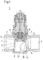
- Fig. 1 shows a valve arrangement 1 according to a first embodiment of the invention.
- the valve arrangement 1 comprises a valve housing 2. Furthermore, the valve arrangement 1 comprises a valve inlet 3 and a valve outlet 4.
- the valve arrangement 1 comprises a main valve element 5 which cooperates with a main valve seat 6.
- the valve element 5 is arranged in a flow path connecting the valve inlet 3 to the valve outlet 4 without passing the valve element 5.
- the valve housing 2 contains an insert 7.
- the insert 7 comprises a gasket element 8 so as to provide a fluid seal.
- the gasket element 8 provides the fluid seal between the valve inlet 3 and the valve outlet 4 so as to block a fluid flow from the valve inlet 3 to the valve outlet 4.
- valve inlet 3 and the valve outlet 4 are facing in opposite directions. Furthermore, the valve inlet 3 and the valve outlet 4 are arranged colinear. This can allow a good fluid flow through the valve arrangement.
- the insert 7 comprising the gasket element 8 is, as shown in Fig. 1 , of a circular cylindrical shape and comprises a circumferential surface 9, the circumferential surface 9 comprising an insert inlet 10 and an insert outlet 11, wherein an insert passage passing through the insert 7 connects the insert inlet 10 to the insert outlet 11.
- the gasket element 8 is arranged on a radially outer side of the circumferential surface 9 and cooperating with the valve housing 2.
- the gasket element is arranged in a gap between the circumferential surface 9 and the valve housing 2 and therefore prevents an undesired fluid flow through the gap.
- the insert inlet 10 extends over more than 30 % of an axial extension of the insert 7. In fact, the insert inlet 10 extends over about 50 % of the axial extension of the insert 7.
- the insert inlet 10 provides a low resistance against fluid entering from the valve inlet 3 and passing towards the valve outlet 4 via the insert inlet 10 and the insert outlet 11.
- the insert inlet 10 has a larger flow cross section than the insert outlet 11. This results in a good fluid flow control through the insert passage.
- the insert 7 comprises an insert foot 12 next to the insert inlet 10. It stabilizes the insert 7 in the valve housing 2.
- the valve housing 2 comprises an insert mount chamber 13 and an actuation device seat 14.
- the insert mount chamber is of a circular cylindrical shape and thus adapted to accommodate the insert 7.
- the valve housing 2 is cast from brass or other metals and afterwards brought to form by machining.
- the insert 7 is cast from plastic. Therefore it is of great advantage using the insert 7 for carrying the gasket element 8.
- designing the interior structure of the valve housing 2 with low detail allows to have a reduced complexity with respect to the insert mount chamber 13.
- the insert mount chamber 13 is basically of a circular cylindrical shape which is easy to manufacture.
- the actuation device seat 14 provides a through hole for inserting the insert into the insert mount chamber 13 it is very easy to place the insert 7 into the insert mount chamber 13.
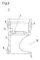
- Fig. 3 shows a cross section of a first embodiment of the insert 7 according to the invention and for use in a valve arrangement 1 according to the first embodiment shown in Fig. 1 .
- the insert 7 comprises the main valve seat 6.
- the main valve seat 6 needs no longer to be cast or machined into a valve housing 2.
- the insert 7 comprises an insert foot 12 for stabilizing the insert 7 in the valve housing 2.
- the insert 7 comprises the gasket element 8.
- the gasket element 8 comprises a gasket section being arranged slanted with respect to a direction of the axial extension of the insert 7.
- the gasket element 8 comprises a gasket section being arranged perpendicular with respect to the direction of the axial extension of the insert 7.
- the gasket element 8 resembles the number seven.
- the slanted gasket section provides the fluid seal between the valve inlet 3 and the valve outlet 4 so as to block the fluid flow from the valve inlet 3 to the valve outlet 4 as can be seen in Fig. 1 .
- gasket section being arranged perpendicular with respect to the direction of the axial extension of the insert 7 provides the sealing between the valve inlet 3 and the actuation device seat 14 preventing leakage of the fluid flow out of the actuation device seat 14, as can also be seen in Fig. 1 .
- the insert inlet 10 has a curved border. Furthermore, it becomes very clear that the insert inlet 10 extends over about 50 % of the axial extension of the insert 7.
- Fig. 7 shows that the insert 7 is basically of a hollow circular cylindrical shape which helps to reduce the material needed for producing the insert 7 and thus reduces producing costs.
- the slanted gasket section covers about 90 % of the axial extension of the insert 7. In fact, it seals all of the gap between the circumferential surface 9 and the valve housing 2 in order to provide a good fluid seal between the valve inlet 3 and the valve outlet 4. Therefore, the fluid flow can only stream from the valve inlet 3 to the valve outlet 4 via the insert inlet 10 and the insert outlet 11.
- Fig. 8 now shows a second embodiment of the valve arrangement 1 according to the invention. Most details of this embodiment are identical to the features as shown and described in view of Fig. 1 . However, in the second embodiment the insert 7 does not comprise the main valve seat 6. The main valve seat 6 is arranged in a presetting element 16 which is rotatably mounted within the insert 7. This allows to have different types of main valve seats and to mount them to the insert 7 depending on the desired usage of the valve arrangement 1.
- the valve housing 2 used in the second embodiment of the valve arrangement 1 is depicted in Fig. 8 is shown in more detail in Fig. 9a and 9b .
- the actuation device seat 14 comprises two cutouts rotated by 90° with respect to the axial extension of the valve inlet 3 and the valve outlet 4. As can be seen in Fig. 2a and 2b , for the first embodiment the cutouts are arranged colinear with the valve inlet 3 and the valve outlet 4. However, as in the second embodiment of the valve arrangement 1 the main valve element actuation device has a different housing which also houses the replaceable valve seat 6, it becomes necessary to use a different geometry for the actuation device seat 14. Otherwise, the valve housing 2 in the second embodiment of the valve arrangement 1 is the same as the valve housing 2 in the first embodiment of the valve arrangement 1.
- Fig. 10 now shows a third embodiment of the valve arrangement 1 according to the present invention.
- the insert 7 comprises a dynamic valve element 15. This allows for having a constant pressure over the main valve element 5.
- the dynamic valve element 15 will throttle the flow with rising pressure difference and open the dynamic valve with falling pressure difference so as to keep the pressure over the main valve element 5 at a stable level.
- the insert 7 according to the invention as well as the valve arrangement 1 according to the invention provide a solution for coming to an easily implementable fluid seal between the valve inlet 3 and the valve outlet 4.
- the gasket element 8 is provided on the insert 7.
- the gasket element 8 allows fluid flow from the valve inlet 3 to the valve outlet 4 only via the insert inlet 10 and the insert outlet 11.
- the solution allows low production costs for the valve arrangement 1.
Landscapes
- Engineering & Computer Science (AREA)
- General Engineering & Computer Science (AREA)
- Mechanical Engineering (AREA)
- Physics & Mathematics (AREA)
- Thermal Sciences (AREA)
- Chemical & Material Sciences (AREA)
- Combustion & Propulsion (AREA)
- Fluid Mechanics (AREA)
- General Physics & Mathematics (AREA)
- Automation & Control Theory (AREA)
- Lift Valve (AREA)
Abstract
Description
- The present invention relates to a valve arrangement comprising a valve housing, a valve inlet, a valve outlet, a main valve element and a main valve seat, the main valve seat being arranged in a flow path between the valve inlet and the valve outlet and the main valve element cooperating with the main valve seat, the valve housing containing an insert, the insert comprising a gasket element so as to provide a fluid seal.
- Such a valve arrangement is known, for example from
DE 10 2013 010 433 A1 . - Furthermore, the invention relates to an insert for a valve arrangement comprising a valve housing, a valve inlet, a valve outlet, a main valve element and a main valve seat, the main valve seat being arranged in a flow path between the valve inlet and the valve outlet and the main valve element cooperating with the main valve seat.
- Such inserts are used in valve arrangements, for example, to provide a sealing between the valve inlet and an actuation device seat so as to prevent leakage of a fluid flow out of the actuation device seat.
- Leakage is also undesired from the valve inlet to the valve outlet. To prevent such leaking, usually the valve housing is designed such that it is cast as a massive element, so that the valve seat is the only opening for the fluid flow from the valve inlet to the valve outlet.
- However, casting the valve housing in such a way was found to be expensive as a lot of material may be needed to cast the massive valve housing or as sophisticated machining of the valve housing is necessary.
- The objective of the invention is therefore to provide a valve arrangement with a good fluid seal between the inlet and the outlet at low costs.
- The problem is solved by the valve arrangement as given in the outset in that the gasket element comprises a gasket section being arranged slanted with respect to a direction of the axial extension of the insert.
- Using the gasket element on the insert for providing the fluid seal will result in good fluid sealing at low costs. The machining of the valve housing may become less sophisticated as the gasket element may be arranged such that an interior of the valve housing may be designed with low complexity. Basically only one gasket is necessary to provide for a tight separation of inlet and outlet. The valve housing can still be made of metal and preferred of brass material. To spare as much brass as possible, it is an advantage to as little metal material as possible. Therefore, the housing has huge in- and outlet openings. The insert containing the valve seat and the slanted gasket element section is used to divide flow inlet and flow outlet.
- It is preferred that the valve inlet and/or the valve outlet comprise a middle axis which is perpendicular to a middle axis of the insert. This means that they are facing in opposite directions or that they are angled by 90°. This can provide a typical valve geometry. In one embodiment the valve inlet and the valve outlet are arranged collinear. This may be advantageous for a good fluid flow through the valve arrangement. However, in some embodiments the valve inlet and the valve outlet face in directions enclosing a 90° angle between them. This allows to have the fluid flow deflected by 90° from the valve inlet to the valve outlet.
- Preferably the insert is of a cylindrical shape. Even more preferably, the insert is of a circular cylindrical shape. In some embodiments though the insert is of a rectangular cylindrical shape. The rectangular cylindrical shape can allow for easy keyed insertion of the insert into the valve housing while a circular cylindrical shape can be beneficial for flow characteristics of the fluid flow.
- In a preferred embodiment of the invention, the insert is of a circular cylindrical shape and comprises a circumferential surface, the circumferential surface comprising an insert inlet and an insert outlet, wherein an insert passage passing through the insert connects the insert inlet to the insert outlet, the gasket element being arranged on a radially outer side of the circumferential surface and cooperating with the valve housing. This is a highly preferred design of the insert as it may allow both good flow sealing and good flow characteristics through the insert. Preferably, the insert inlet and the insert outlet are arranged colinear. Preferably, the insert inlet and the insert outlet are facing in opposite directions. It is most preferred that the valve inlet faces the insert inlet and that the valve outlet faces the insert outlet.
- It is preferred that the insert inlet covers more than 30 % of an axial extension of the insert. Preferably, the insert inlet covers more than 40 % of the axial extension of the insert. It is even more preferred, that the insert inlet covers more than 50 % of the axial extension of the insert. Furthermore, it is preferred that the insert inlet covers less than 65 % of the axial extension of the insert. Furthermore, it is preferred that the insert inlet covers less than 55 % of the axial extension of the insert. Most preferably, the insert inlet covers less than 45 % of the axial extension of the insert. Having the insert inlet covering an amount of the axial extension of the insert as given above may allow a good fluid flow through the insert. Furthermore, the amount of material needed for the insert can be reduced when the insert inlet takes a considerably large area of the circumferential surface.
- In a preferred embodiment of the invention the insert inlet has a larger flow cross section than the insert outlet. This can allow a flow reduction at the valve outlet. The flow cross section of the insert inlet may be two times larger than the flow cross section of the insert outlet. It is preferred that the flow cross section of the valve inlet is even three times larger, four times larger, or most preferably ten times larger than the flow cross section of the insert outlet. It is preferred that the valve inlet has a rim having a curved shape. It is furthermore preferred, that the insert outlet is of a rectangular shape in a viewing direction perpendicular to the axial extension of the insert.
- Preferably, the slanted gasket section covers more than 50 % of the axial extension of the insert. It is more preferred that the slanted gasket section covers more than 60 %, more preferably more than 70 %, more preferably more than 80 %, more preferably more than 90 %, and most preferably 100 % of the axial extension of the insert. In a preferred embodiment the slanted gasket section is of an elliptical shape surrounding at least 50 % of the circumferential surface of the insert. Even more preferred is, that the slanted gasket section surrounds more than 60 %, more preferably more than 80 %, more preferably more than 90 % and most preferably 100 % of the circumferential surface of the insert.
- In a preferred embodiment of the invention, the valve housing comprises an actuation device seat for a main valve element actuation device, the insert providing a sealing between the valve inlet and the actuation device seat preventing leakage of the fluid flow out of the actuation device seat. A preferred actuation device is a thermostat device. Such sealings are known. However, using the insert for providing the sealing between the valve inlet and the valve outlet and between the valve inlet and the actuation device seat in a combined way adds a further function to the insert. This may allow for compact design and reduction of the number of parts of the valve arrangement.
- It is preferred that the gasket element comprises a gasket section being arranged perpendicular with respect to the direction of the axial extension of the insert. This way a single gasket element can provide both, the fluid seal between the valve inlet and the valve outlet so as to block the fluid flow from the valve inlet to the valve outlet and the sealing between the valve inlet and the actuation device seat preventing leakage of the fluid flow out of the actuation device seat. In some embodiments though, instead of a single gasket with the slanted gasket section and the perpendicular arranged gasket section, two separate gaskets are provided replacing the single one. The gasket section being arranged perpendicular with respect to the direction of the axial extension of the insert preferably is an O-ring. The O-ring is preferably integrally formed with the slanted gasket section.
- In a preferred embodiment of the invention the gasket element resembles the
number 7 in a side view of the insert. This gives a good sealing both between the valve inlet and the valve outlet and between the valve inlet and the actuation device seat. Thus, it is preferred that the slanted gasket section is of an elliptical shape and completely surrounds the circumferential surface of the insert. It is furthermore preferred that the perpendicularly arranged gasket section completely surrounds the circumferential surface of the insert. Furthermore, it is preferred that the slanted gasket section and the perpendicular gasket section form an integral part with each other. - Preferably, the insert is made of a first castable material and the gasket element is made of a second castable material. It is highly preferred that the insert is made of a castable or moldable material. Preferably, the gasket element is molded to the insert. Preferably, the insert is made of a plastic material. It is furthermore preferred that the gasket element is made of a rubber material. In general, it is preferred that the rigidity of the insert material is larger than the rigidity of the gasket element. Thus, the weight of the valve arrangement can be low and the form of the insert can easily be predetermined depending on the valve geometry.
- It is preferred that the insert comprises an insert foot for stabilizing the insert in the valve housing. The insert foot is preferably a lower section of the insert adjacent to the insert inlet. Most preferably the insert foot is an axial end section of the circumferential surface. The insert foot may be omitted in order to safe material. Then the valve arrangement preferably comprises an insert holder so as to replace the function of the insert foot.
- Preferably, the insert comprises the main valve seat. This allows providing the main valve seat easily when casting the insert. In case the valve seat wears out it may furthermore be easily replaced together with the insert. In some alternative embodiments of the invention however, the insert comprises a main valve seat mount. Then a removable main valve seat may be mounted to the insert.
- It is preferred that the insert comprises a dynamic valve element. This way the valve element may be equipped with a dynamic valve element in addition to the main valve element. This may allow to come to a constant fluid flow for a predetermined opening position of the main valve element even at variable inlet pressure. The insert comprising the dynamic valve element may easily replace an insert without the dynamic valve element so as to easily add the dynamic valve element to the valve arrangement.
- Furthermore, the invention is solved by an insert as laid out in the outset suitable for use in the previously described valve arrangement.
- This insert allows to have a valve arrangement with a good fluid seal between the valve inlet and the valve outlet at low costs.
- In the following, the invention will be described with reference to the attached figures, in which:
- Fig. 1
- shows a first embodiment of the valve arrangement according to the invention;
- Fig. 2a+b
- shows a valve housing for the valve arrangement according to the first embodiment of the invention;
- Fig. 3
- shows a cross section of a first embodiment of the insert for the valve arrangement according to the invention;
- Fig. 4
- shows a side view of a first embodiment of the insert for the valve arrangement according to a first embodiment of the invention;
- Fig. 5
- shows a perspective top view of the embodiment of the insert shown in
Fig. 3 and4 ; - Fig. 6
- shows another perspective top view of the embodiment of the insert as shown in the
Fig. 3 to 5 ; - Fig. 7
- shows a perspective bottom view of the embodiment of the insert shown in
Fig. 3 to 6 ; - Fig. 8
- shows a second embodiment of the valve arrangement according to the invention;
- Fig. 9a+b
- shows a valve housing of the valve arrangement of the second embodiment of the invention; and
- Fig. 10
- shows a third embodiment of the valve arrangement according to the invention.
- Reference figures are introduced into the claims and the following detailed description of embodiments of the invention only in order to improve readability of the claims. The reference signs are in no way meant to be limiting.
-
Fig. 1 shows avalve arrangement 1 according to a first embodiment of the invention. Thevalve arrangement 1 comprises avalve housing 2. Furthermore, thevalve arrangement 1 comprises avalve inlet 3 and avalve outlet 4. Thevalve arrangement 1 comprises amain valve element 5 which cooperates with amain valve seat 6. Thevalve element 5 is arranged in a flow path connecting thevalve inlet 3 to thevalve outlet 4 without passing thevalve element 5. - The
valve housing 2 contains aninsert 7. Theinsert 7 comprises agasket element 8 so as to provide a fluid seal. Thegasket element 8 provides the fluid seal between thevalve inlet 3 and thevalve outlet 4 so as to block a fluid flow from thevalve inlet 3 to thevalve outlet 4. - Having the
gasket element 8 blocking the fluid flow allows a simplified design of thevalve housing 2 as the machining of thevalve housing 2 does not need to be so sophisticated anymore, as can be seen inFig. 2a and Fig. 2b which will be discussed in more detail further below. - As can be seen in
Fig. 1 , thevalve inlet 3 and thevalve outlet 4 are facing in opposite directions. Furthermore, thevalve inlet 3 and thevalve outlet 4 are arranged colinear. This can allow a good fluid flow through the valve arrangement. - The
insert 7 comprising thegasket element 8 is, as shown inFig. 1 , of a circular cylindrical shape and comprises acircumferential surface 9, thecircumferential surface 9 comprising aninsert inlet 10 and aninsert outlet 11, wherein an insert passage passing through theinsert 7 connects theinsert inlet 10 to theinsert outlet 11. Thegasket element 8 is arranged on a radially outer side of thecircumferential surface 9 and cooperating with thevalve housing 2. Thus, the gasket element is arranged in a gap between thecircumferential surface 9 and thevalve housing 2 and therefore prevents an undesired fluid flow through the gap. - As shown in
Fig.1 , theinsert inlet 10 extends over more than 30 % of an axial extension of theinsert 7. In fact, theinsert inlet 10 extends over about 50 % of the axial extension of theinsert 7. Thus, theinsert inlet 10 provides a low resistance against fluid entering from thevalve inlet 3 and passing towards thevalve outlet 4 via theinsert inlet 10 and theinsert outlet 11. Furthermore, it can be seen that theinsert inlet 10 has a larger flow cross section than theinsert outlet 11. This results in a good fluid flow control through the insert passage. Theinsert 7 comprises aninsert foot 12 next to theinsert inlet 10. It stabilizes theinsert 7 in thevalve housing 2. - Coming now to
Fig. 2 , thevalve housing 2 will be described in more detail. As depicted, thevalve housing 2 comprises aninsert mount chamber 13 and anactuation device seat 14. The insert mount chamber is of a circular cylindrical shape and thus adapted to accommodate theinsert 7. Thevalve housing 2 is cast from brass or other metals and afterwards brought to form by machining. On the other hand theinsert 7 is cast from plastic. Therefore it is of great advantage using theinsert 7 for carrying thegasket element 8. Then designing the interior structure of thevalve housing 2 with low detail allows to have a reduced complexity with respect to theinsert mount chamber 13. Theinsert mount chamber 13 is basically of a circular cylindrical shape which is easy to manufacture. Furthermore, as theactuation device seat 14 provides a through hole for inserting the insert into theinsert mount chamber 13 it is very easy to place theinsert 7 into theinsert mount chamber 13. -
Fig. 3 shows a cross section of a first embodiment of theinsert 7 according to the invention and for use in avalve arrangement 1 according to the first embodiment shown inFig. 1 . Theinsert 7 comprises themain valve seat 6. Thus, themain valve seat 6 needs no longer to be cast or machined into avalve housing 2. Furthermore, theinsert 7 comprises aninsert foot 12 for stabilizing theinsert 7 in thevalve housing 2. - As can be seen in the side view depicted in
Fig. 4 , theinsert 7 comprises thegasket element 8. Thegasket element 8 comprises a gasket section being arranged slanted with respect to a direction of the axial extension of theinsert 7. Furthermore, thegasket element 8 comprises a gasket section being arranged perpendicular with respect to the direction of the axial extension of theinsert 7. In the side view, thegasket element 8 resembles the number seven. Thus, the slanted gasket section provides the fluid seal between thevalve inlet 3 and thevalve outlet 4 so as to block the fluid flow from thevalve inlet 3 to thevalve outlet 4 as can be seen inFig. 1 . Furthermore, the gasket section being arranged perpendicular with respect to the direction of the axial extension of theinsert 7 provides the sealing between thevalve inlet 3 and theactuation device seat 14 preventing leakage of the fluid flow out of theactuation device seat 14, as can also be seen inFig. 1 . - In the perspective top view shown in
Fig. 5 , it becomes more apparent that theinsert inlet 10 has a curved border. Furthermore, it becomes very clear that theinsert inlet 10 extends over about 50 % of the axial extension of theinsert 7. - In
Fig. 6 then it can be seen that theinsert outlet 11 has a smaller flow cross section than theinsert inlet 10. As explained earlier, this allows to have a good control over the fluid flow passing through the valve arrangement. -
Fig. 7 shows that theinsert 7 is basically of a hollow circular cylindrical shape which helps to reduce the material needed for producing theinsert 7 and thus reduces producing costs. The slanted gasket section covers about 90 % of the axial extension of theinsert 7. In fact, it seals all of the gap between thecircumferential surface 9 and thevalve housing 2 in order to provide a good fluid seal between thevalve inlet 3 and thevalve outlet 4. Therefore, the fluid flow can only stream from thevalve inlet 3 to thevalve outlet 4 via theinsert inlet 10 and theinsert outlet 11. -
Fig. 8 now shows a second embodiment of thevalve arrangement 1 according to the invention. Most details of this embodiment are identical to the features as shown and described in view ofFig. 1 . However, in the second embodiment theinsert 7 does not comprise themain valve seat 6. Themain valve seat 6 is arranged in apresetting element 16 which is rotatably mounted within theinsert 7. This allows to have different types of main valve seats and to mount them to theinsert 7 depending on the desired usage of thevalve arrangement 1. - The
valve housing 2 used in the second embodiment of thevalve arrangement 1 is depicted inFig. 8 is shown in more detail inFig. 9a and 9b . Theactuation device seat 14 comprises two cutouts rotated by 90° with respect to the axial extension of thevalve inlet 3 and thevalve outlet 4. As can be seen inFig. 2a and 2b , for the first embodiment the cutouts are arranged colinear with thevalve inlet 3 and thevalve outlet 4. However, as in the second embodiment of thevalve arrangement 1 the main valve element actuation device has a different housing which also houses thereplaceable valve seat 6, it becomes necessary to use a different geometry for theactuation device seat 14. Otherwise, thevalve housing 2 in the second embodiment of thevalve arrangement 1 is the same as thevalve housing 2 in the first embodiment of thevalve arrangement 1. -
Fig. 10 now shows a third embodiment of thevalve arrangement 1 according to the present invention. Most of the details are identical to the first embodiment and the second embodiment shown inFig. 1 and8 respectively. However, in the third embodiment, theinsert 7 comprises adynamic valve element 15. This allows for having a constant pressure over themain valve element 5. Thedynamic valve element 15 will throttle the flow with rising pressure difference and open the dynamic valve with falling pressure difference so as to keep the pressure over themain valve element 5 at a stable level. - The
insert 7 according to the invention as well as thevalve arrangement 1 according to the invention provide a solution for coming to an easily implementable fluid seal between thevalve inlet 3 and thevalve outlet 4. Thegasket element 8 is provided on theinsert 7. Thegasket element 8 allows fluid flow from thevalve inlet 3 to thevalve outlet 4 only via theinsert inlet 10 and theinsert outlet 11. The solution allows low production costs for thevalve arrangement 1. - The present invention is not limited to the embodiments shown and described. Furthermore, all of the features described in view of the different embodiments may also be combined in any way between different embodiments.
Claims (14)
- A valve arrangement (1) comprising a valve housing (2), a valve inlet (3), a valve outlet (4), a main valve element (5) and a main valve seat (6), the main valve seat (6) being arranged in a flow path between the valve inlet (3) and the valve outlet (4) and the main valve element (5) cooperating with the main valve seat (6), the valve housing (2) containing an insert (7), the insert (7) comprising a gasket element (8) so as to provide a fluid seal, characterized in that the gasket element (8) comprises a gasket section being arranged slanted with respect to a direction of the axial extension of the insert (7).
- The valve arrangement according to claim 1, characterized in that the valve inlet (3) and/or the valve outlet (4) comprise a middle axis which is perpendicular to a middle axis of the insert (7).
- The valve arrangement according to claim 1 or claim 2, characterized in that the insert (7) is of a cylindrical shape.
- The valve arrangement according to claim 3, characterized in that the insert (7) is of a circular cylindrical shape and comprises a circumferential surface (9), the circumferential surface (9) comprising an insert inlet (10) and an insert outlet (11), wherein an insert passage passing through the insert (7) connects the insert inlet (10) to the insert outlet (11), the gasket element (8) being arranged on a radially outer side of the circumferential surface (9) and cooperating with the valve housing (2).
- The valve arrangement according to claim 4, characterized in that the insert inlet (10) extends over more than 30% of an axial extension of the insert (7).
- The valve arrangement according to claim 4 or claim 5, characterized in that the insert inlet (10) has a larger flow cross section than the insert outlet (11).
- The valve arrangement according to any of the claims 1 to 6, characterized in that the valve housing (2) comprises an actuation device seat (14) for a main valve element actuation device, the insert (7) providing a sealing between the valve inlet (3) and the actuation device seat (14) preventing leakage of the fluid flow out of the actuation device seat (14).
- The valve arrangement according to any of the claims 1 to 7, characterized in that the gasket element (8) comprises a gasket section being arranged perpendicular with respect to the direction of the axial extension of the insert (7).
- The valve arrangement according to any of the claims 1 to 8, characterized in that the gasket element (8) resembles the number seven in a side view of the insert (7).
- The valve arrangement according to any of the claims 1 to 9, characterized in that the insert (7) is made of a first castable material and the gasket element (8) is made of a second castable material.
- The valve arrangement according to any of the claims 1 to 10, characterized in that the insert (7) comprises an insert foot (12) for stabilizing the insert (7) in the valve housing (2).
- The valve arrangement according to any of the claims 1 to 11, characterized in that the insert (7) comprises the main valve seat (6).
- The valve arrangement according to any of the claims 1 to 12, characterized in that the insert (7) comprises a dynamic valve element (15).
- An insert (7) for a valve arrangement (1) according to any of claims 1 to 13.
Priority Applications (3)
| Application Number | Priority Date | Filing Date | Title |
|---|---|---|---|
| EP16151413.8A EP3193062B1 (en) | 2016-01-15 | 2016-01-15 | Valve arrangement and insert for a valve arrangement |
| RU2016150884A RU2659593C2 (en) | 2016-01-15 | 2016-12-23 | Valve device and liner for valve device |
| CN201710015471.3A CN107023698A (en) | 2016-01-15 | 2017-01-10 | Valve gear and the insert for valve gear |
Applications Claiming Priority (1)
| Application Number | Priority Date | Filing Date | Title |
|---|---|---|---|
| EP16151413.8A EP3193062B1 (en) | 2016-01-15 | 2016-01-15 | Valve arrangement and insert for a valve arrangement |
Publications (2)
| Publication Number | Publication Date |
|---|---|
| EP3193062A1 true EP3193062A1 (en) | 2017-07-19 |
| EP3193062B1 EP3193062B1 (en) | 2019-01-09 |
Family
ID=55173785
Family Applications (1)
| Application Number | Title | Priority Date | Filing Date |
|---|---|---|---|
| EP16151413.8A Active EP3193062B1 (en) | 2016-01-15 | 2016-01-15 | Valve arrangement and insert for a valve arrangement |
Country Status (3)
| Country | Link |
|---|---|
| EP (1) | EP3193062B1 (en) |
| CN (1) | CN107023698A (en) |
| RU (1) | RU2659593C2 (en) |
Cited By (1)
| Publication number | Priority date | Publication date | Assignee | Title |
|---|---|---|---|---|
| SE1950893A1 (en) * | 2019-07-12 | 2021-01-13 | Purmo Group Sweden Ab | Valve arrangement |
Citations (6)
| Publication number | Priority date | Publication date | Assignee | Title |
|---|---|---|---|---|
| DE3605606A1 (en) * | 1986-02-21 | 1987-08-27 | Knebel & Roettger Fa | Pressure reduction valve |
| EP1193432A2 (en) * | 2000-09-30 | 2002-04-03 | Danfoss A/S | Valve, in particular radiator valve |
| FR2965035A1 (en) * | 2010-09-22 | 2012-03-23 | Watts Ind France | PRESSURE LIMITER, ESPECIALLY FOR DOMESTIC WATER SUPPLY INSTALLATION |
| DE102013010433A1 (en) | 2012-06-29 | 2014-01-23 | Danfoss A/S | Thermostatic controlled valve e.g. radiator valve for use in controlling fluid flow, has valve seat that comprises insert assembly and spindle which are inserted from same side into valve housing |
| WO2014138786A1 (en) * | 2013-03-12 | 2014-09-18 | Gsa Industries (Aust) Pty Ltd | Water temperature regulating valve |
| EP2818960A1 (en) * | 2013-06-24 | 2014-12-31 | Danfoss A/S | Membrane for dynamic valve |
Family Cites Families (2)
| Publication number | Priority date | Publication date | Assignee | Title |
|---|---|---|---|---|
| DE102005060120B4 (en) * | 2005-12-16 | 2014-08-21 | Danfoss A/S | Radiator Valve Installation |
| EP2482160B1 (en) * | 2011-01-27 | 2013-11-06 | Danfoss A/S | Valve arrangement for controlling a flow of a heating or cooling fluid |
-
2016
- 2016-01-15 EP EP16151413.8A patent/EP3193062B1/en active Active
- 2016-12-23 RU RU2016150884A patent/RU2659593C2/en not_active IP Right Cessation
-
2017
- 2017-01-10 CN CN201710015471.3A patent/CN107023698A/en active Pending
Patent Citations (6)
| Publication number | Priority date | Publication date | Assignee | Title |
|---|---|---|---|---|
| DE3605606A1 (en) * | 1986-02-21 | 1987-08-27 | Knebel & Roettger Fa | Pressure reduction valve |
| EP1193432A2 (en) * | 2000-09-30 | 2002-04-03 | Danfoss A/S | Valve, in particular radiator valve |
| FR2965035A1 (en) * | 2010-09-22 | 2012-03-23 | Watts Ind France | PRESSURE LIMITER, ESPECIALLY FOR DOMESTIC WATER SUPPLY INSTALLATION |
| DE102013010433A1 (en) | 2012-06-29 | 2014-01-23 | Danfoss A/S | Thermostatic controlled valve e.g. radiator valve for use in controlling fluid flow, has valve seat that comprises insert assembly and spindle which are inserted from same side into valve housing |
| WO2014138786A1 (en) * | 2013-03-12 | 2014-09-18 | Gsa Industries (Aust) Pty Ltd | Water temperature regulating valve |
| EP2818960A1 (en) * | 2013-06-24 | 2014-12-31 | Danfoss A/S | Membrane for dynamic valve |
Cited By (2)
| Publication number | Priority date | Publication date | Assignee | Title |
|---|---|---|---|---|
| SE1950893A1 (en) * | 2019-07-12 | 2021-01-13 | Purmo Group Sweden Ab | Valve arrangement |
| SE543651C2 (en) * | 2019-07-12 | 2021-05-18 | Purmo Group Sweden Ab | Valve arrangement comprising press fit pre-setting sleeve |
Also Published As
| Publication number | Publication date |
|---|---|
| EP3193062B1 (en) | 2019-01-09 |
| CN107023698A (en) | 2017-08-08 |
| RU2659593C2 (en) | 2018-07-03 |
| RU2016150884A3 (en) | 2018-06-25 |
| RU2016150884A (en) | 2018-06-25 |
Similar Documents
| Publication | Publication Date | Title |
|---|---|---|
| JP6778251B2 (en) | Control panel in the valve | |
| EP3155302B1 (en) | High conductance valve for fluids and vapors | |
| US20220025978A1 (en) | Combination multi-port valve | |
| US9989162B2 (en) | Dual cartridge temperature control valve | |
| EP2495478B1 (en) | Mechanical seal | |
| US20130037738A1 (en) | Ball valve | |
| US10935161B2 (en) | Control valve with guide vane | |
| US20230193861A1 (en) | Egr valve system | |
| EP3193062B1 (en) | Valve arrangement and insert for a valve arrangement | |
| JP2022003281A (en) | Bellows valve and manufacturing method of the same | |
| JP2002503315A (en) | Pressure equalizer | |
| US8052151B2 (en) | Sealing arrangement | |
| US3361407A (en) | Throttling valve and seats therefor | |
| JP5676163B2 (en) | Single lever faucet | |
| JP7036555B2 (en) | Ball valve | |
| JP3453424B2 (en) | Ball type check valve and water stopcock integrally provided with the check valve | |
| JP2018048560A (en) | Pressure regulating valve | |
| JP6804038B2 (en) | Hot water mixing faucet | |
| JP6845993B2 (en) | Faucet device and its manufacturing method | |
| JP7787691B2 (en) | Manufacturing method for packing-integrated check valve | |
| JP7286927B2 (en) | Hot and cold water mixing faucet | |
| CN213393629U (en) | Valve core assembly | |
| JP3225466U (en) | Lead type check valve | |
| JP2018069226A (en) | Ion exchanger | |
| JP6625880B2 (en) | Gas control unit |
Legal Events
| Date | Code | Title | Description |
|---|---|---|---|
| PUAI | Public reference made under article 153(3) epc to a published international application that has entered the european phase |
Free format text: ORIGINAL CODE: 0009012 |
|
| STAA | Information on the status of an ep patent application or granted ep patent |
Free format text: STATUS: THE APPLICATION HAS BEEN PUBLISHED |
|
| AK | Designated contracting states |
Kind code of ref document: A1 Designated state(s): AL AT BE BG CH CY CZ DE DK EE ES FI FR GB GR HR HU IE IS IT LI LT LU LV MC MK MT NL NO PL PT RO RS SE SI SK SM TR |
|
| AX | Request for extension of the european patent |
Extension state: BA ME |
|
| STAA | Information on the status of an ep patent application or granted ep patent |
Free format text: STATUS: REQUEST FOR EXAMINATION WAS MADE |
|
| 17P | Request for examination filed |
Effective date: 20180102 |
|
| RBV | Designated contracting states (corrected) |
Designated state(s): AL AT BE BG CH CY CZ DE DK EE ES FI FR GB GR HR HU IE IS IT LI LT LU LV MC MK MT NL NO PL PT RO RS SE SI SK SM TR |
|
| RIC1 | Information provided on ipc code assigned before grant |
Ipc: F16K 43/00 20060101ALI20180326BHEP Ipc: F16K 1/52 20060101ALI20180326BHEP Ipc: F16J 15/06 20060101ALI20180326BHEP Ipc: F16K 27/02 20060101ALI20180326BHEP Ipc: F16K 41/04 20060101AFI20180326BHEP Ipc: F24D 19/10 20060101ALI20180326BHEP |
|
| GRAP | Despatch of communication of intention to grant a patent |
Free format text: ORIGINAL CODE: EPIDOSNIGR1 |
|
| STAA | Information on the status of an ep patent application or granted ep patent |
Free format text: STATUS: GRANT OF PATENT IS INTENDED |
|
| INTG | Intention to grant announced |
Effective date: 20180717 |
|
| GRAS | Grant fee paid |
Free format text: ORIGINAL CODE: EPIDOSNIGR3 |
|
| GRAA | (expected) grant |
Free format text: ORIGINAL CODE: 0009210 |
|
| STAA | Information on the status of an ep patent application or granted ep patent |
Free format text: STATUS: THE PATENT HAS BEEN GRANTED |
|
| AK | Designated contracting states |
Kind code of ref document: B1 Designated state(s): AL AT BE BG CH CY CZ DE DK EE ES FI FR GB GR HR HU IE IS IT LI LT LU LV MC MK MT NL NO PL PT RO RS SE SI SK SM TR |
|
| REG | Reference to a national code |
Ref country code: GB Ref legal event code: FG4D |
|
| REG | Reference to a national code |
Ref country code: CH Ref legal event code: EP Ref country code: AT Ref legal event code: REF Ref document number: 1087733 Country of ref document: AT Kind code of ref document: T Effective date: 20190115 |
|
| REG | Reference to a national code |
Ref country code: IE Ref legal event code: FG4D |
|
| REG | Reference to a national code |
Ref country code: DE Ref legal event code: R096 Ref document number: 602016009076 Country of ref document: DE |
|
| REG | Reference to a national code |
Ref country code: NL Ref legal event code: MP Effective date: 20190109 |
|
| REG | Reference to a national code |
Ref country code: LT Ref legal event code: MG4D |
|
| PG25 | Lapsed in a contracting state [announced via postgrant information from national office to epo] |
Ref country code: NL Free format text: LAPSE BECAUSE OF FAILURE TO SUBMIT A TRANSLATION OF THE DESCRIPTION OR TO PAY THE FEE WITHIN THE PRESCRIBED TIME-LIMIT Effective date: 20190109 |
|
| REG | Reference to a national code |
Ref country code: AT Ref legal event code: MK05 Ref document number: 1087733 Country of ref document: AT Kind code of ref document: T Effective date: 20190109 |
|
| PG25 | Lapsed in a contracting state [announced via postgrant information from national office to epo] |
Ref country code: ES Free format text: LAPSE BECAUSE OF FAILURE TO SUBMIT A TRANSLATION OF THE DESCRIPTION OR TO PAY THE FEE WITHIN THE PRESCRIBED TIME-LIMIT Effective date: 20190109 Ref country code: LT Free format text: LAPSE BECAUSE OF FAILURE TO SUBMIT A TRANSLATION OF THE DESCRIPTION OR TO PAY THE FEE WITHIN THE PRESCRIBED TIME-LIMIT Effective date: 20190109 Ref country code: PL Free format text: LAPSE BECAUSE OF FAILURE TO SUBMIT A TRANSLATION OF THE DESCRIPTION OR TO PAY THE FEE WITHIN THE PRESCRIBED TIME-LIMIT Effective date: 20190109 Ref country code: FI Free format text: LAPSE BECAUSE OF FAILURE TO SUBMIT A TRANSLATION OF THE DESCRIPTION OR TO PAY THE FEE WITHIN THE PRESCRIBED TIME-LIMIT Effective date: 20190109 Ref country code: SE Free format text: LAPSE BECAUSE OF FAILURE TO SUBMIT A TRANSLATION OF THE DESCRIPTION OR TO PAY THE FEE WITHIN THE PRESCRIBED TIME-LIMIT Effective date: 20190109 Ref country code: PT Free format text: LAPSE BECAUSE OF FAILURE TO SUBMIT A TRANSLATION OF THE DESCRIPTION OR TO PAY THE FEE WITHIN THE PRESCRIBED TIME-LIMIT Effective date: 20190509 Ref country code: NO Free format text: LAPSE BECAUSE OF FAILURE TO SUBMIT A TRANSLATION OF THE DESCRIPTION OR TO PAY THE FEE WITHIN THE PRESCRIBED TIME-LIMIT Effective date: 20190409 |
|
| PG25 | Lapsed in a contracting state [announced via postgrant information from national office to epo] |
Ref country code: HR Free format text: LAPSE BECAUSE OF FAILURE TO SUBMIT A TRANSLATION OF THE DESCRIPTION OR TO PAY THE FEE WITHIN THE PRESCRIBED TIME-LIMIT Effective date: 20190109 Ref country code: RS Free format text: LAPSE BECAUSE OF FAILURE TO SUBMIT A TRANSLATION OF THE DESCRIPTION OR TO PAY THE FEE WITHIN THE PRESCRIBED TIME-LIMIT Effective date: 20190109 Ref country code: BG Free format text: LAPSE BECAUSE OF FAILURE TO SUBMIT A TRANSLATION OF THE DESCRIPTION OR TO PAY THE FEE WITHIN THE PRESCRIBED TIME-LIMIT Effective date: 20190409 Ref country code: IS Free format text: LAPSE BECAUSE OF FAILURE TO SUBMIT A TRANSLATION OF THE DESCRIPTION OR TO PAY THE FEE WITHIN THE PRESCRIBED TIME-LIMIT Effective date: 20190509 Ref country code: LV Free format text: LAPSE BECAUSE OF FAILURE TO SUBMIT A TRANSLATION OF THE DESCRIPTION OR TO PAY THE FEE WITHIN THE PRESCRIBED TIME-LIMIT Effective date: 20190109 Ref country code: GR Free format text: LAPSE BECAUSE OF FAILURE TO SUBMIT A TRANSLATION OF THE DESCRIPTION OR TO PAY THE FEE WITHIN THE PRESCRIBED TIME-LIMIT Effective date: 20190410 |
|
| REG | Reference to a national code |
Ref country code: CH Ref legal event code: PL |
|
| PG25 | Lapsed in a contracting state [announced via postgrant information from national office to epo] |
Ref country code: LU Free format text: LAPSE BECAUSE OF NON-PAYMENT OF DUE FEES Effective date: 20190115 |
|
| REG | Reference to a national code |
Ref country code: DE Ref legal event code: R097 Ref document number: 602016009076 Country of ref document: DE |
|
| REG | Reference to a national code |
Ref country code: BE Ref legal event code: MM Effective date: 20190131 |
|
| REG | Reference to a national code |
Ref country code: IE Ref legal event code: MM4A |
|
| PG25 | Lapsed in a contracting state [announced via postgrant information from national office to epo] |
Ref country code: RO Free format text: LAPSE BECAUSE OF FAILURE TO SUBMIT A TRANSLATION OF THE DESCRIPTION OR TO PAY THE FEE WITHIN THE PRESCRIBED TIME-LIMIT Effective date: 20190109 Ref country code: SK Free format text: LAPSE BECAUSE OF FAILURE TO SUBMIT A TRANSLATION OF THE DESCRIPTION OR TO PAY THE FEE WITHIN THE PRESCRIBED TIME-LIMIT Effective date: 20190109 Ref country code: CZ Free format text: LAPSE BECAUSE OF FAILURE TO SUBMIT A TRANSLATION OF THE DESCRIPTION OR TO PAY THE FEE WITHIN THE PRESCRIBED TIME-LIMIT Effective date: 20190109 Ref country code: MC Free format text: LAPSE BECAUSE OF FAILURE TO SUBMIT A TRANSLATION OF THE DESCRIPTION OR TO PAY THE FEE WITHIN THE PRESCRIBED TIME-LIMIT Effective date: 20190109 Ref country code: AL Free format text: LAPSE BECAUSE OF FAILURE TO SUBMIT A TRANSLATION OF THE DESCRIPTION OR TO PAY THE FEE WITHIN THE PRESCRIBED TIME-LIMIT Effective date: 20190109 Ref country code: AT Free format text: LAPSE BECAUSE OF FAILURE TO SUBMIT A TRANSLATION OF THE DESCRIPTION OR TO PAY THE FEE WITHIN THE PRESCRIBED TIME-LIMIT Effective date: 20190109 Ref country code: IT Free format text: LAPSE BECAUSE OF FAILURE TO SUBMIT A TRANSLATION OF THE DESCRIPTION OR TO PAY THE FEE WITHIN THE PRESCRIBED TIME-LIMIT Effective date: 20190109 Ref country code: EE Free format text: LAPSE BECAUSE OF FAILURE TO SUBMIT A TRANSLATION OF THE DESCRIPTION OR TO PAY THE FEE WITHIN THE PRESCRIBED TIME-LIMIT Effective date: 20190109 Ref country code: DK Free format text: LAPSE BECAUSE OF FAILURE TO SUBMIT A TRANSLATION OF THE DESCRIPTION OR TO PAY THE FEE WITHIN THE PRESCRIBED TIME-LIMIT Effective date: 20190109 |
|
| PLBE | No opposition filed within time limit |
Free format text: ORIGINAL CODE: 0009261 |
|
| STAA | Information on the status of an ep patent application or granted ep patent |
Free format text: STATUS: NO OPPOSITION FILED WITHIN TIME LIMIT |
|
| PG25 | Lapsed in a contracting state [announced via postgrant information from national office to epo] |
Ref country code: SM Free format text: LAPSE BECAUSE OF FAILURE TO SUBMIT A TRANSLATION OF THE DESCRIPTION OR TO PAY THE FEE WITHIN THE PRESCRIBED TIME-LIMIT Effective date: 20190109 Ref country code: BE Free format text: LAPSE BECAUSE OF NON-PAYMENT OF DUE FEES Effective date: 20190131 |
|
| 26N | No opposition filed |
Effective date: 20191010 |
|
| PG25 | Lapsed in a contracting state [announced via postgrant information from national office to epo] |
Ref country code: CH Free format text: LAPSE BECAUSE OF NON-PAYMENT OF DUE FEES Effective date: 20190131 Ref country code: LI Free format text: LAPSE BECAUSE OF NON-PAYMENT OF DUE FEES Effective date: 20190131 |
|
| PG25 | Lapsed in a contracting state [announced via postgrant information from national office to epo] |
Ref country code: IE Free format text: LAPSE BECAUSE OF NON-PAYMENT OF DUE FEES Effective date: 20190115 |
|
| PG25 | Lapsed in a contracting state [announced via postgrant information from national office to epo] |
Ref country code: SI Free format text: LAPSE BECAUSE OF FAILURE TO SUBMIT A TRANSLATION OF THE DESCRIPTION OR TO PAY THE FEE WITHIN THE PRESCRIBED TIME-LIMIT Effective date: 20190109 |
|
| PG25 | Lapsed in a contracting state [announced via postgrant information from national office to epo] |
Ref country code: TR Free format text: LAPSE BECAUSE OF FAILURE TO SUBMIT A TRANSLATION OF THE DESCRIPTION OR TO PAY THE FEE WITHIN THE PRESCRIBED TIME-LIMIT Effective date: 20190109 |
|
| PG25 | Lapsed in a contracting state [announced via postgrant information from national office to epo] |
Ref country code: MT Free format text: LAPSE BECAUSE OF NON-PAYMENT OF DUE FEES Effective date: 20190115 |
|
| PG25 | Lapsed in a contracting state [announced via postgrant information from national office to epo] |
Ref country code: CY Free format text: LAPSE BECAUSE OF FAILURE TO SUBMIT A TRANSLATION OF THE DESCRIPTION OR TO PAY THE FEE WITHIN THE PRESCRIBED TIME-LIMIT Effective date: 20190109 |
|
| PG25 | Lapsed in a contracting state [announced via postgrant information from national office to epo] |
Ref country code: HU Free format text: LAPSE BECAUSE OF FAILURE TO SUBMIT A TRANSLATION OF THE DESCRIPTION OR TO PAY THE FEE WITHIN THE PRESCRIBED TIME-LIMIT; INVALID AB INITIO Effective date: 20160115 |
|
| PG25 | Lapsed in a contracting state [announced via postgrant information from national office to epo] |
Ref country code: MK Free format text: LAPSE BECAUSE OF FAILURE TO SUBMIT A TRANSLATION OF THE DESCRIPTION OR TO PAY THE FEE WITHIN THE PRESCRIBED TIME-LIMIT Effective date: 20190109 |
|
| P01 | Opt-out of the competence of the unified patent court (upc) registered |
Effective date: 20230617 |
|
| PGFP | Annual fee paid to national office [announced via postgrant information from national office to epo] |
Ref country code: GB Payment date: 20251204 Year of fee payment: 11 |
|
| PGFP | Annual fee paid to national office [announced via postgrant information from national office to epo] |
Ref country code: FR Payment date: 20251222 Year of fee payment: 11 |
|
| PGFP | Annual fee paid to national office [announced via postgrant information from national office to epo] |
Ref country code: DE Payment date: 20251203 Year of fee payment: 11 |