JP6778251B2 - Control panel in the valve - Google Patents
Control panel in the valve Download PDFInfo
- Publication number
- JP6778251B2 JP6778251B2 JP2018500440A JP2018500440A JP6778251B2 JP 6778251 B2 JP6778251 B2 JP 6778251B2 JP 2018500440 A JP2018500440 A JP 2018500440A JP 2018500440 A JP2018500440 A JP 2018500440A JP 6778251 B2 JP6778251 B2 JP 6778251B2
- Authority
- JP
- Japan
- Prior art keywords
- valve
- control plate
- control
- bonnet
- fluid conduit
- Prior art date
- Legal status (The legal status is an assumption and is not a legal conclusion. Google has not performed a legal analysis and makes no representation as to the accuracy of the status listed.)
- Active
Links
Images


Classifications
-
- F—MECHANICAL ENGINEERING; LIGHTING; HEATING; WEAPONS; BLASTING
- F16—ENGINEERING ELEMENTS AND UNITS; GENERAL MEASURES FOR PRODUCING AND MAINTAINING EFFECTIVE FUNCTIONING OF MACHINES OR INSTALLATIONS; THERMAL INSULATION IN GENERAL
- F16K—VALVES; TAPS; COCKS; ACTUATING-FLOATS; DEVICES FOR VENTING OR AERATING
- F16K1/00—Lift valves or globe valves, i.e. cut-off apparatus with closure members having at least a component of their opening and closing motion perpendicular to the closing faces
- F16K1/32—Details
- F16K1/34—Cutting-off parts, e.g. valve members, seats
- F16K1/36—Valve members
-
- F—MECHANICAL ENGINEERING; LIGHTING; HEATING; WEAPONS; BLASTING
- F16—ENGINEERING ELEMENTS AND UNITS; GENERAL MEASURES FOR PRODUCING AND MAINTAINING EFFECTIVE FUNCTIONING OF MACHINES OR INSTALLATIONS; THERMAL INSULATION IN GENERAL
- F16K—VALVES; TAPS; COCKS; ACTUATING-FLOATS; DEVICES FOR VENTING OR AERATING
- F16K1/00—Lift valves or globe valves, i.e. cut-off apparatus with closure members having at least a component of their opening and closing motion perpendicular to the closing faces
- F16K1/32—Details
-
- B—PERFORMING OPERATIONS; TRANSPORTING
- B29—WORKING OF PLASTICS; WORKING OF SUBSTANCES IN A PLASTIC STATE IN GENERAL
- B29C—SHAPING OR JOINING OF PLASTICS; SHAPING OF MATERIAL IN A PLASTIC STATE, NOT OTHERWISE PROVIDED FOR; AFTER-TREATMENT OF THE SHAPED PRODUCTS, e.g. REPAIRING
- B29C37/00—Component parts, details, accessories or auxiliary operations, not covered by group B29C33/00 or B29C35/00
- B29C37/0078—Measures or configurations for obtaining anchoring effects in the contact areas between layers
- B29C37/0082—Mechanical anchoring
- B29C37/0085—Mechanical anchoring by means of openings in the layers
-
- B—PERFORMING OPERATIONS; TRANSPORTING
- B29—WORKING OF PLASTICS; WORKING OF SUBSTANCES IN A PLASTIC STATE IN GENERAL
- B29C—SHAPING OR JOINING OF PLASTICS; SHAPING OF MATERIAL IN A PLASTIC STATE, NOT OTHERWISE PROVIDED FOR; AFTER-TREATMENT OF THE SHAPED PRODUCTS, e.g. REPAIRING
- B29C70/00—Shaping composites, i.e. plastics material comprising reinforcements, fillers or preformed parts, e.g. inserts
- B29C70/68—Shaping composites, i.e. plastics material comprising reinforcements, fillers or preformed parts, e.g. inserts by incorporating or moulding on preformed parts, e.g. inserts or layers, e.g. foam blocks
- B29C70/78—Moulding material on one side only of the preformed part
- B29C70/80—Moulding sealing material into closure members
-
- F—MECHANICAL ENGINEERING; LIGHTING; HEATING; WEAPONS; BLASTING
- F16—ENGINEERING ELEMENTS AND UNITS; GENERAL MEASURES FOR PRODUCING AND MAINTAINING EFFECTIVE FUNCTIONING OF MACHINES OR INSTALLATIONS; THERMAL INSULATION IN GENERAL
- F16K—VALVES; TAPS; COCKS; ACTUATING-FLOATS; DEVICES FOR VENTING OR AERATING
- F16K1/00—Lift valves or globe valves, i.e. cut-off apparatus with closure members having at least a component of their opening and closing motion perpendicular to the closing faces
- F16K1/32—Details
- F16K1/34—Cutting-off parts, e.g. valve members, seats
- F16K1/42—Valve seats
-
- F—MECHANICAL ENGINEERING; LIGHTING; HEATING; WEAPONS; BLASTING
- F16—ENGINEERING ELEMENTS AND UNITS; GENERAL MEASURES FOR PRODUCING AND MAINTAINING EFFECTIVE FUNCTIONING OF MACHINES OR INSTALLATIONS; THERMAL INSULATION IN GENERAL
- F16K—VALVES; TAPS; COCKS; ACTUATING-FLOATS; DEVICES FOR VENTING OR AERATING
- F16K1/00—Lift valves or globe valves, i.e. cut-off apparatus with closure members having at least a component of their opening and closing motion perpendicular to the closing faces
- F16K1/32—Details
- F16K1/34—Cutting-off parts, e.g. valve members, seats
- F16K1/46—Attachment of sealing rings
-
- F—MECHANICAL ENGINEERING; LIGHTING; HEATING; WEAPONS; BLASTING
- F16—ENGINEERING ELEMENTS AND UNITS; GENERAL MEASURES FOR PRODUCING AND MAINTAINING EFFECTIVE FUNCTIONING OF MACHINES OR INSTALLATIONS; THERMAL INSULATION IN GENERAL
- F16K—VALVES; TAPS; COCKS; ACTUATING-FLOATS; DEVICES FOR VENTING OR AERATING
- F16K11/00—Multiple-way valves, e.g. mixing valves; Pipe fittings incorporating such valves
- F16K11/02—Multiple-way valves, e.g. mixing valves; Pipe fittings incorporating such valves with all movable sealing faces moving as one unit
- F16K11/06—Multiple-way valves, e.g. mixing valves; Pipe fittings incorporating such valves with all movable sealing faces moving as one unit comprising only sliding valves, i.e. sliding closure elements
- F16K11/072—Multiple-way valves, e.g. mixing valves; Pipe fittings incorporating such valves with all movable sealing faces moving as one unit comprising only sliding valves, i.e. sliding closure elements with pivoted closure members
- F16K11/074—Multiple-way valves, e.g. mixing valves; Pipe fittings incorporating such valves with all movable sealing faces moving as one unit comprising only sliding valves, i.e. sliding closure elements with pivoted closure members with flat sealing faces
- F16K11/0743—Multiple-way valves, e.g. mixing valves; Pipe fittings incorporating such valves with all movable sealing faces moving as one unit comprising only sliding valves, i.e. sliding closure elements with pivoted closure members with flat sealing faces with both the supply and the discharge passages being on one side of the closure plates
-
- F—MECHANICAL ENGINEERING; LIGHTING; HEATING; WEAPONS; BLASTING
- F16—ENGINEERING ELEMENTS AND UNITS; GENERAL MEASURES FOR PRODUCING AND MAINTAINING EFFECTIVE FUNCTIONING OF MACHINES OR INSTALLATIONS; THERMAL INSULATION IN GENERAL
- F16K—VALVES; TAPS; COCKS; ACTUATING-FLOATS; DEVICES FOR VENTING OR AERATING
- F16K25/00—Details relating to contact between valve members and seat
- F16K25/005—Particular materials for seats or closure elements
-
- F—MECHANICAL ENGINEERING; LIGHTING; HEATING; WEAPONS; BLASTING
- F16—ENGINEERING ELEMENTS AND UNITS; GENERAL MEASURES FOR PRODUCING AND MAINTAINING EFFECTIVE FUNCTIONING OF MACHINES OR INSTALLATIONS; THERMAL INSULATION IN GENERAL
- F16K—VALVES; TAPS; COCKS; ACTUATING-FLOATS; DEVICES FOR VENTING OR AERATING
- F16K27/00—Construction of housing; Use of materials therefor
- F16K27/02—Construction of housing; Use of materials therefor of lift valves
- F16K27/0236—Diaphragm cut-off apparatus
-
- F—MECHANICAL ENGINEERING; LIGHTING; HEATING; WEAPONS; BLASTING
- F16—ENGINEERING ELEMENTS AND UNITS; GENERAL MEASURES FOR PRODUCING AND MAINTAINING EFFECTIVE FUNCTIONING OF MACHINES OR INSTALLATIONS; THERMAL INSULATION IN GENERAL
- F16K—VALVES; TAPS; COCKS; ACTUATING-FLOATS; DEVICES FOR VENTING OR AERATING
- F16K41/00—Spindle sealings
- F16K41/10—Spindle sealings with diaphragm, e.g. shaped as bellows or tube
- F16K41/103—Spindle sealings with diaphragm, e.g. shaped as bellows or tube the diaphragm and the closure member being integrated in one member
-
- F—MECHANICAL ENGINEERING; LIGHTING; HEATING; WEAPONS; BLASTING
- F16—ENGINEERING ELEMENTS AND UNITS; GENERAL MEASURES FOR PRODUCING AND MAINTAINING EFFECTIVE FUNCTIONING OF MACHINES OR INSTALLATIONS; THERMAL INSULATION IN GENERAL
- F16K—VALVES; TAPS; COCKS; ACTUATING-FLOATS; DEVICES FOR VENTING OR AERATING
- F16K41/00—Spindle sealings
- F16K41/10—Spindle sealings with diaphragm, e.g. shaped as bellows or tube
- F16K41/12—Spindle sealings with diaphragm, e.g. shaped as bellows or tube with approximately flat diaphragm
-
- F—MECHANICAL ENGINEERING; LIGHTING; HEATING; WEAPONS; BLASTING
- F16—ENGINEERING ELEMENTS AND UNITS; GENERAL MEASURES FOR PRODUCING AND MAINTAINING EFFECTIVE FUNCTIONING OF MACHINES OR INSTALLATIONS; THERMAL INSULATION IN GENERAL
- F16K—VALVES; TAPS; COCKS; ACTUATING-FLOATS; DEVICES FOR VENTING OR AERATING
- F16K7/00—Diaphragm valves or cut-off apparatus, e.g. with a member deformed, but not moved bodily, to close the passage ; Pinch valves
- F16K7/12—Diaphragm valves or cut-off apparatus, e.g. with a member deformed, but not moved bodily, to close the passage ; Pinch valves with flat, dished, or bowl-shaped diaphragm
- F16K7/14—Diaphragm valves or cut-off apparatus, e.g. with a member deformed, but not moved bodily, to close the passage ; Pinch valves with flat, dished, or bowl-shaped diaphragm arranged to be deformed against a flat seat
-
- F—MECHANICAL ENGINEERING; LIGHTING; HEATING; WEAPONS; BLASTING
- F16—ENGINEERING ELEMENTS AND UNITS; GENERAL MEASURES FOR PRODUCING AND MAINTAINING EFFECTIVE FUNCTIONING OF MACHINES OR INSTALLATIONS; THERMAL INSULATION IN GENERAL
- F16K—VALVES; TAPS; COCKS; ACTUATING-FLOATS; DEVICES FOR VENTING OR AERATING
- F16K27/00—Construction of housing; Use of materials therefor
- F16K27/10—Welded housings
- F16K27/102—Welded housings for lift-valves
Description
関連出願の相互参照
本願は、米国特許法第119条(e)およびPCT第8条の下で、2015年7月9日に出願され、「CONTROL PLATE IN A VALVE」と題された米国仮出願第62/190,478号、および2016年2月8日に出願され、「CONTROL PLATE IN A VALVE」と題された仮出願第62/292,526号の利益を主張するものであり、各々のすべての記載内容を、あらゆる目的のために引用により本明細書に援用する。
Cross-reference to related applications This application was filed on July 9, 2015 under 35 USC 119 (e) and 35 PCT, and is a US provisional application entitled "CONTROL PLATE IN A VALVE". Claiming the interests of provisional application Nos. 62 / 292,526, filed on February 8, 2016, and entitled "CONTROL PLATE IN A VALVE", Nos. 62 / 190,478, respectively. All statements are hereby incorporated by reference for all purposes.
背景
本発明は、最大開状態と最大閉状態との間で能動的に配置され得、通過する流体の流れを調整する、流体制御弁の可動部分に関する。本発明は、半導体装置、医薬品、またはファインケミカルズを作る工業プロセス内での流体送達の比例制御または比例制御を目的とする弁、および比例制御と同時に、完全に閉状態に漏洩なく閉止することを要求する多くの同様の高純度流体送達システムにおいて特に有用である。当技術分野において、弁閉止を強化させる金属製要素とエラストマー要素との多くの組み合わせが知られている。
Background The present invention relates to a moving part of a fluid control valve that can be actively placed between a maximally open state and a maximally closed state and regulates the flow of flowing fluid. The present invention requires a valve for proportional or proportional control of fluid delivery within an industrial process for making semiconductor devices, pharmaceuticals, or fine chemicals, and proportional control, as well as a completely closed state without leakage. It is particularly useful in many similar high-purity fluid delivery systems. Many combinations of metal and elastomeric elements that enhance valve closure are known in the art.
概要
出願人は、さまざまなサイズの弁オリフィス用の可動弁要素の独自の製造可能な構成を発明した。可動円盤状要素は、平坦面を有し、当該平坦面は、閉止時は弁の対称軸に対して概ね垂直であり、細いリップまたはオリフィス・リッジ(ridge)によって囲まれたオリフィスに平行に近づいたり遠ざかったりする。弁構造のこの組み合わせは、流体経路要素組み合わせのジェット・アンド・シート・クラス(jet&seat class)と称されることがある。本開示において、オリフィスを囲む細いリップ(通称、ジェット)に対して閉じる、表面が平坦な要素(通称、弁座)は、制御板と呼ばれることが多い。弁閉止状態における耐漏洩性は、オリフィスを囲むリップまたはリッジを構成する材料よりも軟らかい材料を制御板に選択的に取り入れることによって強化される。制御板材料がオリフィス・リッジ−リップよりも軟らかいことで、制御板表面がオリフィス・リッジ−リップに押し当たると、制御板表面の弾性変形が可能になり、制御板とオリフィス・リッジ−リップとの間に生じる封止が強化される。高純度流体経路の中にねじ山を有することに関連した問題を回避するために、開示の構成は、溶接または締りばめ部材を利用できる。
Overview The applicant has invented a unique manufacturable configuration of movable valve elements for valve orifices of various sizes. The movable disc-like element has a flat surface that, when closed, is approximately perpendicular to the axis of symmetry of the valve and approaches parallel to the orifice surrounded by a thin lip or orifice ridge. Or move away. This combination of valve structures is sometimes referred to as the jet & seat class of fluid path element combinations. In the present disclosure, a flat surface element (commonly known as a valve seat) that closes with respect to a thin lip (commonly known as a jet) surrounding an orifice is often referred to as a control plate. Leakage resistance in the valve closed state is enhanced by selectively incorporating into the control plate a material that is softer than the material that makes up the lip or ridge that surrounds the orifice. Since the control plate material is softer than the orifice ridge-lip, when the control plate surface presses against the orifice ridge-lip, elastic deformation of the control plate surface is possible, and the control plate and the orifice ridge-lip become The sealing that occurs between them is strengthened. To avoid problems associated with having threads in the high purity fluid path, the disclosed configurations can utilize welded or clamped members.
一実施形態は、ポリマーインサートの外径と弁座ハウジングカウンターボアの内径との間の隙間に押し込まれた金属製リテーナリングによって所定の位置に保持されたポリマー材の小径の中央インサートを有する金属製の弁座ハウジングを備える。別の実施形態は、ポリマーリングの内径と制御板の穿孔流路の小内径との間の隙間に押し込まれた金属製リテーナリングと、ポリマーリングの外径と制御板の穿孔流路の大内径との間の隙間に押し込まれた金属製リテーナリングとによって所定の位置に保持されたポリマー材のリングを備える。別の実施形態は、耐食ニッケル合金の小径の中央インサートを備え、中央インサートは、通常、より大きな制御板に溶接されることによって保持される。別の実施形態は、実質的に耐食ニッケル合金から作られた制御板を備え、制御板は、別の合金から必要に応じて作られたカバー部材を有する。 One embodiment is made of metal with a small diameter central insert of polymer material held in place by a metal retainer pushed into the gap between the outer diameter of the polymer insert and the inner diameter of the valve seat housing counterbore. The valve seat housing is provided. Another embodiment is a metal retainer ring pushed into the gap between the inner diameter of the polymer ring and the smaller inner diameter of the perforated flow path of the control plate, and the outer diameter of the polymer ring and the larger inner diameter of the perforated flow path of the control plate. It comprises a ring of polymer material held in place by a metal retainer ring pushed into the gap between the and. Another embodiment comprises a small diameter central insert of corrosion resistant nickel alloy, which is usually held by welding to a larger control plate. Another embodiment comprises a control plate made substantially from a corrosion resistant nickel alloy, the control plate having a cover member optionally made from another alloy.
本開示の一態様において、平面状のオリフィス・リッジによって囲まれた流体コンジット開口部に封止係合するように構成された弁制御板が提供される。弁制御板は、弁制御板本体と、弁座インサートとを備える。弁制御板本体は、第1硬度を有する第1材料から形成される。弁制御板本体は、流体コンジット開口部に面するように構成された第1面を有する。弁制御板本体は、弁制御板本体の第1面に規定される凹部を有する。弁座インサートは、第1硬度よりも軟らかい第2硬度を有する第2材料から形成される。弁座インサートは、流体コンジット開口部に面するように、かつ平面状のオリフィス・リッジに封止係合するように構成された第1面を有する。弁座インサートは、凹部に収容されている。 In one aspect of the present disclosure, a valve control plate configured to seal and engage a fluid conduit opening surrounded by a planar orifice ridge is provided. The valve control plate includes a valve control plate main body and a valve seat insert. The valve control plate body is formed from a first material having a first hardness. The valve control plate body has a first surface configured to face the fluid conduit opening. The valve control plate body has a recess defined on the first surface of the valve control plate body. The valve seat insert is formed from a second material having a second hardness that is softer than the first hardness. The valve seat insert has a first surface configured to face the fluid conduit opening and to seal and engage the planar orifice ridge. The valve seat insert is housed in a recess.
いくつかの実施形態において、凹部は、カウンターボアまたは穿孔溝のうちの一方である。 In some embodiments, the recess is one of a counterbore or a perforated groove.
いくつかの実施形態において、第2材料の量は、第1材料の量よりも少ない。
いくつかの実施形態において、第1材料は金属であり、凹部は、弁制御板本体の第1面に規定されるカウンターボアであり、第2材料はポリマー材であり、弁座インサートは、弁座インサートの外周に位置するリテーナリングによってカウンターボアに保持される。例示的な実施形態によると、弁座インサートは、4mm以下の直径を有する平面状のオリフィス・リッジに係合するように構成されてもよい。
In some embodiments, the amount of the second material is less than the amount of the first material.
In some embodiments, the first material is metal, the recess is the counterbore defined on the first surface of the valve control plate body, the second material is polymer material, and the valve seat insert is the valve. It is held in the counterbore by a retainer ring located on the outer circumference of the seat insert. According to an exemplary embodiment, the valve seat insert may be configured to engage a planar orifice ridge with a diameter of 4 mm or less.
いくつかの実施形態において、第2材料はポリマー材であり、凹部は、弁制御板本体の第1面に規定される穿孔溝であり、弁座インサートはリング形状であり、第1材料は金属である。いくつかの実施形態において、弁座インサートは、弁座インサートの内周に位置する内側リテーナリングおよび弁座インサートの外周に位置する外側リテーナリングによって穿孔溝に保持される。その他の実施形態において、弁座インサートは、支柱、柱、および/またはブリッジによって穿孔溝に保持される。例示的な実施形態によると、弁座インサートは、4mm以上の直径を有する平面状のオリフィス・リッジに係合するように構成されてもよい。 In some embodiments, the second material is a polymeric material, the recess is a perforated groove defined on the first surface of the valve control plate body, the valve seat insert is ring shaped, and the first material is metal. Is. In some embodiments, the valve seat insert is held in the perforated groove by an inner retainer ring located on the inner circumference of the valve seat insert and an outer retainer ring located on the outer circumference of the valve seat insert. In other embodiments, the valve seat insert is held in the perforated groove by a strut, column, and / or bridge. According to an exemplary embodiment, the valve seat insert may be configured to engage a planar orifice ridge with a diameter of 4 mm or more.
いくつかの実施形態において、第1材料は第1金属であり、凹部は、制御板本体の第1面に規定されたカウンターボアであり、第2材料は第1金属とは異なる第2金属であり、弁座インサートは、弁座インサートを制御板本体に溶接することによってカウンターボアに保持される。例示的な実施形態によると、弁座インサートは、4mm以下の直径を有する平面状のオリフィス・リッジに係合するように構成されてもよい。 In some embodiments, the first material is a first metal, the recess is a counterbore defined on the first surface of the control panel body, and the second material is a second metal different from the first metal. Yes, the valve seat insert is held in the counterbore by welding the valve seat insert to the control plate body. According to an exemplary embodiment, the valve seat insert may be configured to engage a planar orifice ridge with a diameter of 4 mm or less.
いくつかの実施形態において、平面状のオリフィス・リッジに封止係合する弁座インサートの第1面の一部は、平面状である。 In some embodiments, a portion of the first surface of the valve seat insert that seals and engages the planar orifice ridge is planar.
本開示の別の態様において、制御弁体と合わせて使用する弁ボンネットが提供される。制御弁体は、第1硬度を有する第1材料から形成され、平面状のオリフィス・リッジによって囲まれた流体コンジット開口部を有する。弁ボンネットは、ボンネット本体と、外周においてボンネット本体に封止係合された弁ダイヤフラムと、ダイヤフラムに固定された制御軸とを備え、制御軸は、制御軸から突き出るシャンクを有し、弁ボンネットは、さらに、弁制御板を備える。弁制御板はシャンクに固定され、弁制御板の少なくとも一部は、第1硬度よりも軟らかい第2硬度を有する第2材料から形成され、弁制御板の少なくとも一部は、平面状のオリフィス・リッジに封止係合するように構成される。いくつかの実施形態において、弁制御板の少なくとも一部は、円形および非円形のうちの一方である平面状のオリフィス・リッジに係合するように構成されている。いくつかの実施形態において、弁ダイヤフラムはボンネット本体と一体形成され、制御軸はダイヤフラムと一体形成される。その他の実施形態において、ダイヤフラムは、ボンネット本体とは別に形成され、ボンネット本体に溶接される。 In another aspect of the present disclosure, a valve bonnet for use in conjunction with a control valve body is provided. The control valve body is formed from a first material having a first hardness and has a fluid conduit opening surrounded by a planar orifice ridge. The valve bonnet includes a bonnet body, a valve diaphragm sealed and engaged with the bonnet body on the outer circumference, and a control shaft fixed to the diaphragm. The control shaft has a shank protruding from the control shaft, and the valve bonnet Further, a valve control plate is provided. The valve control plate is fixed to the shank, at least a part of the valve control plate is formed of a second material having a second hardness that is softer than the first hardness, and at least a part of the valve control plate is a flat orifice. It is configured to seal and engage the ridge. In some embodiments, at least a portion of the valve control plate is configured to engage a planar orifice ridge that is either circular or non-circular. In some embodiments, the valve diaphragm is integrally formed with the bonnet body and the control shaft is integrally formed with the diaphragm. In other embodiments, the diaphragm is formed separately from the bonnet body and welded to the bonnet body.
いくつかの実施形態において、弁制御板は、さらに、弁制御板本体を含み、弁制御板本体は、弁制御板本体に規定される穿孔溝を有し、弁制御板の少なくとも一部は、穿孔溝を充填する弁座インサートである。いくつかの実施形態において、弁座インサートは穿孔溝にモールドされ、いくつかの実施形態において、弁座インサートは、支柱、柱、および/またはブリッジによって穿孔溝に保持される。 In some embodiments, the valve control plate further comprises a valve control plate body, the valve control plate body having a perforated groove defined in the valve control plate body, and at least a portion of the valve control plate. A valve seat insert that fills a perforated groove. In some embodiments, the valve seat insert is molded into the perforation groove, and in some embodiments, the valve seat insert is held in the perforation groove by a strut, column, and / or bridge.
本開示の別の態様において、制御弁が提供される。制御弁は、弁本体と、弁本体に固定されたボンネット本体と、弁ダイヤフラムと、制御軸と、弁制御板とを備える。弁本体は、第1流体コンジット開口部で終端する流体導入口コンジットと、第2流体コンジット開口部で始端する流体排出口コンジットと、第1硬度を有する第1材料から形成され、第1流体コンジット開口部を囲むオリフィス・リッジとを有する。弁ダイヤフラムは、弁ダイヤフラムの外周においてボンネット本体に封止係合している。制御軸はダイヤフラムに固定され、制御軸からシャンクが突き出ている。弁制御板はシャンクに固定され、弁制御板の少なくとも一部は、第1硬度よりも軟らかい第2硬度を有する第2材料から形成され、弁制御板の少なくとも一部は、オリフィス・リッジに封止係合するように構成されている。 In another aspect of the present disclosure, a control valve is provided. The control valve includes a valve body, a bonnet body fixed to the valve body, a valve diaphragm, a control shaft, and a valve control plate. The valve body is formed of a fluid inlet conduit terminating at the first fluid conduit opening, a fluid outlet conduit terminating at the second fluid conduit opening, and a first material having a first hardness, and is a first fluid conduit. It has an orifice ridge that surrounds the opening. The valve diaphragm is hermetically engaged with the bonnet body on the outer circumference of the valve diaphragm. The control shaft is fixed to the diaphragm, and the shank protrudes from the control shaft. The valve control plate is fixed to the shank, at least part of the valve control plate is made of a second material with a second hardness that is softer than the first hardness, and at least part of the valve control plate is sealed in an orifice ridge. It is configured to be stop-engaged.
いくつかの実施形態において、オリフィス・リッジは、円形または非円形である。
いくつかの実施形態において、弁制御板は、弁制御板本体を含み、弁制御板本体は、弁制御板本体に規定される穿孔溝を有し、弁制御板の少なくとも一部は、穿孔溝を充填する弁座インサートである。いくつかの実施形態において、弁座インサートは穿孔溝にモールドされ、いくつかの実施形態において、弁座インサートは、支柱、柱、および/またはブリッジによって穿孔溝に保持される。
In some embodiments, the orifice ridge is circular or non-circular.
In some embodiments, the valve control plate includes a valve control plate body, the valve control plate body has a perforated groove defined in the valve control plate body, and at least a portion of the valve control plate has a perforated groove. It is a valve seat insert that fills. In some embodiments, the valve seat insert is molded into the perforation groove, and in some embodiments, the valve seat insert is held in the perforation groove by a strut, column, and / or bridge.
詳細な説明
本発明の実施形態は、その用途において、以下の説明に記載するまたは図面に示す構成要素の構成および配置の詳細に限定されない。本発明の態様は、その他の実施形態に対応可能であり、さまざまな方法で実施可能、または実行可能である。また、本明細書において使用される表現および用語は、説明の便宜上であって、限定であるとみなされるべきではない。本明細書における、「含む」、「備える」、または「有する」、「含める」、「伴う」、およびそれらの語尾変化の使用は、以下に記載の項目、それらの均等物、およびその他の項目を包含することを意図する。方向を示す形容詞「内側」、「外側」、「上」、「下」、および同様の用語の使用は、設計要素間の相対関係を理解することを助けるためであり、空間における絶対的な方向を意味するものとして解釈されるべきではなく、限定としてみなされるべきでもない。以下の設計の説明において、流体の流れは、通常、第1流体コンジットから、弁の制御部分を経て、第2流体コンジットを通って進むものとして記載する。設計者は、記載の方向が説明の便宜上の事柄であるに過ぎず、流体の流れは、逆の順序で進んでもよく、限定であると考えられるべきではない、と当然理解するだろう。
Detailed Description The embodiments of the present invention are not limited to the details of the configuration and arrangement of the components described in the following description or shown in the drawings in the present application. Aspects of the invention are compatible with other embodiments and can be or can be implemented in a variety of ways. Also, the expressions and terms used herein are for convenience of explanation only and should not be considered limiting. The use of "include", "provide", or "have", "include", "accompany", and their inflections herein is described in the items below, their equivalents, and other items. Is intended to include. The use of the directional adjectives "inside", "outside", "above", "below", and similar terms is to help understand the relative relationships between design elements and is an absolute orientation in space. Should not be construed as meaning, nor should it be considered as a limitation. In the following design description, the fluid flow is typically described as traveling from the first fluid conduit, through the control portion of the valve, and through the second fluid conduit. The designer will naturally understand that the directions of description are for convenience of explanation only, and that the fluid flow may proceed in reverse order and should not be considered limiting.
最近の高純度弁の設計において、ダイヤフラム型の可動封止構造が、好ましい手法である。可動制御要素の容易な動きを可能にしつつ、ダイヤフラムを利用して制御された流体を含めることは、標準的技法となっている。多くのこのような弁設計において、ダイヤフラムは、可動制御要素の役割を果たし、流体コンジット開口部を囲むポリマー材の細いリングにダイヤフラム自体を押し当てることによって、弁閉止が実現される。半導体装置を作る工業プロセス内での流体送達の比例制御または比例制御を目的とする弁を作る設計者は、直接接触型ダイヤフラム弁の漸進制御曲線が不十分であると思うかもしれない。既知の代替設計の1つの様式では、流体コンジット開口部を囲む金属製のリップまたはオリフィス・リッジに近づいたり遠ざかったりする実質的に平坦な制御板を有する。しかしながら、弁を通る流体の流れを遮蔽することにダイヤフラム自体が最適な要素ではない場合、厄介な問題が生じる可能性があり、金属製の構造に対する閉止シーリングは問題になり得る。 In modern high-purity valve designs, a diaphragm-type movable sealing structure is the preferred method. It has become a standard technique to include fluids controlled using diaphragms while allowing easy movement of movable control elements. In many such valve designs, the diaphragm acts as a movable control element, and valve closure is achieved by pressing the diaphragm itself against a thin ring of polymeric material surrounding the fluid conduit opening. Designers who make valves aimed at proportional or proportional control of fluid delivery within the industrial process of making semiconductor devices may find that the gradual control curve of a direct contact diaphragm valve is inadequate. One mode of known alternative design has a substantially flat control plate that approaches or moves away from the metal lip or orifice ridge that surrounds the fluid conduit opening. However, if the diaphragm itself is not the optimal element for blocking the flow of fluid through the valve, a nasty problem can arise and closure sealing for metal structures can be a problem.
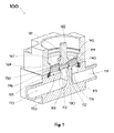
図1は、中央に位置する流体コンジット開口部112を囲むオリフィス・リッジ118に当接する制御板140を有する、ダイヤフラムによる封止を用いた比例制御弁100の代表例を説明する図である。比例制御弁100は、第1流体コンジット110と第2流体コンジット114とを有する弁本体119を備え、第1流体コンジット110および第2流体コンジット114の各々は、弁室150へまたは弁室150から流体を連通させる。比例制御弁100は、さらに、ガスケット165によって弁本体119に封止された弁ボンネット(ボンネット本体)169を備え、ボンネット169は、取り付けられた制御板140の弁室150での動きを可能にするダイヤフラム167を有する。流体の流れの制御方法は、第1流体コンジット110と流体連通している、オリフィス・リッジ118によって囲まれた流体コンジット開口部112を考慮するとさらに理解できる。これによって、制御板140の少なくとも一部は、オリフィス・リッジ118に近づいたり遠ざかったりすることができ、流体が制御可能に流れることができる小さなクリアランスの制御間隙(図示せず)を作る。制御可能な流体の流れは、弁室150内へ移動でき、第2流体コンジット114と流体連通しているオフセット流体コンジット開口部116から出ることができる。この弁100の例において、駆動部(図示せず)が制御軸182に引き戻し力を加えてダイヤフラム167を撓ませることができるので、制御間隙を変更することによって、弁を通るコンダクタンスを調節する。この図1の説明において、弁100は、無流量状態で完全に閉じているので、制御間隙は図示していない。
FIG. 1 is a diagram illustrating a typical example of a
制御板140がオリフィス・リッジ118に接触したときに漏洩のない弁閉止を実現することは困難で有り得、漏洩のない動作とは何であるかという基準も、設計用途によって異なり得る。たとえば、弁出口が水に浸かっているときに気泡をまったく発生させないことは、ある環境においては十分であるかもしれないが、別の状況では、10e−9sccm/秒よりも少ないヘリウムガス漏れ率を有することが要求されるかもしれない。閉止時にポリマー材を金属材料に接触させる弁設計は、閉止構成の中で最も漏洩がない構成を一般的に提供することが知られている。しかし、ポリマー材は、一般に、水分を吸収する。したがって、高純度用途において、制御された流体に晒されるポリマー材の総量を最小限に抑えることが望ましい。代表的な比例制御弁100において、ポリマー量を低減させるというこの目標は、金属製の制御板本体146と、比較的少量のポリマー材のインサート130とを備える制御板140を作ることによって実現される。オリフィス・リッジ118は、ポリマーインサート130に対して「最大全幅」を有すると考えられ得、オリフィス・リッジは、ポリマーインサートの外周に隣接した状態で当該インサートに係合する。
It can be difficult to achieve leak-free valve closure when the
制御板140の金属製の制御板本体146は、中央流体コンジット開口部112に面する側にカウンターボア144を設けた中央貫通孔142を有する平坦な円盤として機械仕上げすることができる。カウンターボア144によって、金属製の制御板本体146が弁座ハウジングとして機能できるようになる。これにより、ポリマー弁座インサート130を弁座ハウジングに保持でき、より適合した少量の封止材を提供できる。説明した弁設計100の製造において、制御板本体146をシャンク181の上に載置する。シャンク181は、制御軸182およびダイヤフラム167から突き出ており、中央貫通孔142を貫通する。電子ビーム、レーザ、TIG、または任意の同等の溶接プロセスを用いて、シャンク181と制御板本体146とを、中央貫通孔142における接点で互いに溶接してもよい。結果生じるわずかな溶接ビードのはみ出しは、カウンターボア144の底部に合うように、機械加工によりいずれも取り除くことができる。次は、カウンターボア144の外径内のポリマー材インサート130の外周の周辺の空間に金属製リテーナリング132を挿入することによって、ポリマー材インサート130をカウンターボア144に載置し、所定の位置に保持できる。次に、良好な弁機能のために必要であれば、完成した組立て品を(たとえば、ラップ仕上げによって)最終的な仕上げにかけて平坦にすることができる。この設計手法は、直径約4mm以下のオリフィス・リッジを有する弁に特に有利である。
The metal
ポリマー材インサート130は、オリフィス・リッジ118の平面状上端部に封止係合するように構成された、平面状の第1面を含む。
The
図2は、中央流体コンジット開口部212を囲むオリフィス・リッジ218に当接する制御板240を有する、ダイヤフラムによる封止を用いた比例制御弁200の代表例を説明する図である。比例制御弁200は、第1流体コンジット210と第2流体コンジット214とを有する弁本体219を備え、第1流体コンジット210および第2流体コンジット214の各々は、弁室250へまたは弁室250から流体を連通させる。比例制御弁200は、さらに、ガスケット265によって弁本体219に封止された弁ボンネット269を備え、ボンネット269は、取り付けられた制御板240の弁室250での動きを可能にするダイヤフラム267を有する。流体の流れの制御方法は、第1流体コンジット210と流体連通している、オリフィス・リッジ218によって囲まれた流体コンジット開口部212を考慮するとさらに理解できる。これによって、制御板240の少なくとも一部は、オリフィス・リッジ218に近づいたり遠ざかったりすることができ、流体が制御可能に流れることができる小さなクリアランスの制御間隙(図示せず)を作る。制御可能な流体の流れは、弁室250内へ移動でき、第2流体コンジット214と流体連通しているオフセット流体コンジット開口部216から出ることができる。この弁200の例において、駆動部(図示せず)が制御軸282に引き戻し力を加えてダイヤフラム267を撓ませることができるので、制御間隙を変更することによって、弁を通るコンダクタンスを調節する。この図2の説明において、弁200は、無流量状態で完全に閉じているので、制御間隙は図示していない。
FIG. 2 is a diagram illustrating a typical example of a
代表的な比例制御弁200において、ポリマー量を低減させるという目標は、金属製の制御板本体246と、比較的小量のポリマー材のリング状インサート230とを備える制御板240を作ることによって実現される。オリフィス・リッジ218は、リング状インサート230に対して「通常の全幅」を有すると考えられ得、オリフィス・リッジは、インサートの内周と外周との間に位置するインサート230のより中央部分に隣接した状態で、当該インサートに係合する。図2は縮尺通りに描かれてはおらず、ポリマーの量は、少なくともいくつかの実施形態に説明されているよりも少なくてもよい、と理解されるべきである。金属製制御板240の制御板本体246は、中央流体コンジット開口部212に面する側に穿孔(つまり、リング状)溝245を設けた中央貫通孔242を有する平坦な円盤として機械仕上げすることができる。穿孔溝245によって、金属製の制御板本体246が弁座ハウジングとして機能できるようになる。これにより、ポリマー材インサート230を弁座ハウジングに保持でき、より適合した少量の封止材を提供できる。説明した弁設計200の製造において、リング状ポリマーインサート230の内径内の穿孔溝245の内径の周辺の空間に金属製の内側リテーナリング234を挿入し、穿孔溝245の外径内のリング状ポリマーインサート230の外周の周辺の空間に金属製の外側リテーナリング236を挿入することによって、リング状ポリマー材インサート230を穿孔溝245に載置し、所定の位置に保持できる。次は、制御軸282およびダイヤフラム267から突き出て中央貫通孔242を貫通するシャンク281の上に制御板240を載置する。電子ビーム、レーザ、TIG、または任意の同等の溶接プロセスを用いて、シャンク281と制御板本体246とを、中央貫通孔242における接点で互いに溶接してもよい。結果生じるわずかな溶接ビードのはみ出しは、機械加工により制御板240の表面から取り除くことができ、リング状ポリマーインサート230上の飛散物も同様である。次に、良好な弁機能のために必要であれば、完成した組立て品を(たとえば、ラップ仕上げによって)最終的な仕上げにかけて平坦にすることができる。この設計手法は、最大全幅が約4mmよりも大きいオリフィス・リッジを有する弁に特に有利である。非円形のオリフィス・リッジ構造である場合、オリフィス・リッジの最大全幅は、直径以外であってもよいと理解されるべきである。
In a typical
上述のポリマー材による水分吸収の問題に加えて、多くの気体がポリマーを介して拡散するだろうことも知られている。拡散は、非常に低い率で発生するが、検出可能な量にまで達する可能性がある。これは、望ましいことではなく、問題であるとさえ考えられる。これに加えて、核科学用途において、放射性気体の問題をはらむ拡散によって、ポリマー材の破壊が同時に起こる可能性がある。金属間封止を有する弁では、これらの問題がないが、このような設計において良好な閉止性能を実現することは難しい。また、非常に清浄な弁の金属製の構成要素間の常温圧接は、潜在的な問題になり得る。1つの設計手法として、2つの異なる金属材料からなる弁を作って常温圧接を回避し、また、異なる硬度を設けて閉止を強化する方法がある。図3、図4、および図5は、金属同士の弁設計を実施するための制御板の実施形態を説明する。 In addition to the problem of water absorption by the polymeric material described above, it is also known that many gases will diffuse through the polymer. Diffusion occurs at a very low rate, but can reach detectable amounts. This is not desirable and may even be considered a problem. In addition to this, in nuclear science applications, the problematic diffusion of radioactive gases can result in simultaneous destruction of the polymeric material. Valves with metal-to-metal seals do not have these problems, but it is difficult to achieve good closing performance in such a design. Also, cold pressure welding between the metal components of a very clean valve can be a potential problem. One design method is to make valves made of two different metal materials to avoid cold pressure welding, and to provide different hardness to strengthen the closure. 3, FIG. 4, and FIG. 5 describe an embodiment of a control plate for carrying out valve design between metals.
ポリマー材インサート230は、オリフィス・リッジ218の平面状上端部に封止係合するように構成された平面状の第1面を含む。
The
図3は、中央流体コンジット開口部312を囲むオリフィス・リッジ318に当接する制御板340を有する、ダイヤフラムによる封止を用いた比例制御弁300の代表例を説明する図である。比例制御弁300は、第1流体コンジット310と第2流体コンジット314とを有する弁本体319を備え、第1流体コンジット310および第2流体コンジット314の各々は、弁室350へまたは弁室350から流体を連通させる。比例制御弁300は、さらに、ガスケット365によって弁本体319に封止された弁ボンネット369を備え、ボンネット369は、取り付けられた制御板340の弁室350での動きを可能にするダイヤフラム367を有する。流体の流れの制御方法は、第1流体コンジット310と流体連通している、オリフィス・リッジ318によって囲まれた流体コンジット開口部312を考慮するとさらに理解できる。これによって、制御板340の少なくとも一部は、オリフィス・リッジ318に近づいたり遠ざかったりすることができ、流体が制御可能に流れることができる小さなクリアランスの制御間隙(図示せず)を作る。制御可能な流体の流れは、弁室350内へ移動でき、第2流体コンジット314と流体連通しているオフセット流体コンジット開口部316から出ることができる。この弁300の例において、駆動部(図示せず)が制御軸382に引き戻し力を加えてダイヤフラム367を撓ませることができるので、制御間隙を変更することによって、弁を通るコンダクタンスを調節する。この図3の説明において、弁300は、無流量状態で完全に閉じているので、制御間隙は図示していない。
FIG. 3 is a diagram illustrating a typical example of a
代表的な比例制御弁300において、金属製の制御板本体346と、オリフィス・リッジ318よりも軟らかい金属製インサート330とを備える制御板340を作ることによって閉止性能を強化できる。オリフィス・リッジ318は、金属製インサート330に対して「最大全幅」を有すると考えられ得、オリフィス・リッジは、金属製インサートの外周に隣接した状態で当該インサートに係合する。制御板340の金属製の制御板本体346は、中央流体コンジット開口部312に面する側にカウンターボア344を設けた中央貫通孔342を有する平坦な円盤として機械仕上げすることができる。カウンターボア344によって、金属製の制御板本体346が弁座ハウジングとして機能できるようになる。これにより、焼なまし、好ましくは、完全焼なましされた耐食金属合金インサート330を弁座ハウジングに保持でき、より適合した封止材を提供できる。説明した弁設計300の製造において、制御板本体346をシャンク381の上に載置する。シャンク381は、制御軸382およびダイヤフラム367から突き出ており、中央貫通孔342を貫通する。電子ビーム、レーザ、TIG、または任意の同等の溶接プロセスを用いて、シャンク381と制御板本体346とを、中央貫通孔342における接点で互いに溶接してもよい。結果生じるわずかな溶接ビードのはみ出しは、カウンターボア344の底部に合うように、機械加工によりいずれも取り除くことができる。次に、インサート330の外周およびカウンターボア344の内径の周りに対する電子ビーム、レーザ、TIG、または任意の同等の溶接プロセスを用いることによって、焼なまし、または完全焼なましされた耐食金属合金インサート330をカウンターボア344に載置し、所定の位置に保持できる。これに代えて、インサート330を保持するためには、金属合金インサート330の外径とカウンターボア344の内径との間の締まりばめで十分であると考えられる場合がある。次に、良好な弁機能のために必要であれば、完成した組立て品を(たとえば、ラップ仕上げまたは単一転ダイヤモンド回転によって)最終的な仕上げにかけて平坦にすることができる。この設計手法は、直径約4mm以下のオリフィス・リッジを有する弁に特に有利である。通常の用途において、オリフィス・リッジ318は、ある合金から作られ、金属合金弁座インサート330は、異なる合金から作られるだろう。材料の1つの主流として、オリフィス・リッジ318にはType316ステンレスを用い、インサート330には耐食ニッケル合金(ヘインズインターナショナル社から入手可能なHastelloy(登録商標)C−22(登録商標)など)を用いる。
In a typical
金属製インサート330は、オリフィス・リッジ318の平面状上端部に封止係合するように構成された平面状の第1面を含む。
The
図4は、中央流体コンジット開口部412を囲むオリフィス・リッジ418に当接する制御板440を有する、ダイヤフラムによる封止を用いた比例制御弁400の代表例を説明する図である。比例制御弁400は、第1流体コンジット410と第2流体コンジット414とを有する弁本体419を備え、第1流体コンジット410および第2流体コンジット414の各々は、弁室450へまたは弁室450から流体を連通させる。比例制御弁400は、さらに、ガスケット465によって弁本体419に封止された弁ボンネット469を備え、ボンネット469は、取り付けられた制御板440の弁室450での動きを可能にするダイヤフラム467を有する。流体の流れの制御方法は、第1流体コンジット410と流体連通している、オリフィス・リッジ418によって囲まれた流体コンジット開口部412を考慮するとさらに理解できる。これによって、制御板440の少なくとも一部は、オリフィス・リッジ418に近づいたり遠ざかったりすることができ、流体が制御可能に流れることができる小さなクリアランスの制御間隙(図示せず)を作る。制御可能な流体の流れは、弁室450内へ移動でき、第2流体コンジット414と流体連通しているオフセット流体コンジット開口部416から出ることができる。この弁400の例において、駆動部(図示せず)が制御軸482に引き戻し力を加えてダイヤフラム467を撓ませることができるので、制御間隙を変更することによって、弁を通るコンダクタンスを調節する。この図4の説明において、弁400は、無流量状態で完全に閉じているので、制御間隙は図示していない。
FIG. 4 is a diagram illustrating a typical example of a
代表的な比例制御弁400において、オリフィス・リッジ418よりも軟らかい金属製の制御板本体446と、金属製のカバー部材430とを備える制御板440を作ることによって閉止性能を強化できる。オリフィス・リッジ418は、制御板本体446に対して「通常の全幅」を有すると考えられ得、オリフィス・リッジは、制御板本体446の内周と外周との間に位置する制御板本体446のより中央部分に隣接した状態で、制御板本体に係合する。制御板440の金属製の制御板本体446は、焼なまし、好ましくは、完全焼なましされた耐食合金から、中央流体コンジット開口部412に面する側にカウンターボア444を設けた中央貫通孔442を有する平坦な円盤として機械仕上げすることができる。カウンターボア444は、可動弁要素へのアクセスを提供することによって、取付プロセスを可能にする。説明した弁設計400の製造において、制御板本体446をシャンク481の上に載置する。シャンク481は、制御軸482およびダイヤフラム467から突き出ており、中央貫通孔442を貫通する。電子ビーム、レーザ、TIG、または任意の同等の溶接プロセスを用いて、シャンク481と制御板本体446とを、中央貫通孔442における接点で互いに溶接してもよい。結果生じるわずかな溶接ビードのはみ出しは、カウンターボア444の底部に合うように、機械加工によりいずれも取り除くことができる。次に、カバー部材430の外周およびカウンターボア444の内径の周りに対して電子ビーム、レーザ、TIG、または任意の同等の溶接プロセスを用いることによって、適した金属製のカバー部材430をカウンターボア444に載置し、所定の位置に保持できる。これに代えて、カバー部材430を保持するためには、金属製のカバー部材430の外径とカウンターボア444の内径との間の締まりばめで十分であると考えられる場合がある。次に、良好な弁機能のために必要であれば、完成した組立て品を(たとえば、ラップ仕上げまたは単一転ダイヤモンド回転によって、)最終的な仕上げにかけて平坦にすることができる。この設計手法は、最大全幅が約4mmよりも大きいオリフィス・リッジを有する弁に特に有利である。非円形のオリフィス・リッジ構造である場合、オリフィス・リッジの最大全幅は、直径以外であってもよいと理解されるべきである。通常の用途において、オリフィス・リッジ418は、1つの合金から作られ、金属製の制御板本体446は、1つの異なる合金から作られるだろう。材料の1つの主流として、オリフィス・リッジ418にはType316ステンレスを用い、制御板本体446には耐食ニッケル合金(ヘインズインターナショナル社から入手可能なHastelloy(登録商標)C−22(登録商標)など)を用いる。金属製のカバー部材430は、オリフィス・リッジ418もしくは制御板440と同じ材料、またはさらに別の異なる合金から作られてもよい。
In a typical
カバー部材430および制御板本体446は、制御板440のシャンク481への溶接の改良を可能にするために、図4において別々の構成要素として設けられている。まず、制御板本体446がシャンク481に溶接される。次に、カバー部材430が制御板本体446に溶接される。その後、カバー部材430および制御板本体446を(たとえば、ラップ仕上げ、単一転ダイヤモンド回転、または別の方法によって)仕上げにかけて平坦にすることができる。
The
いくつかの実施形態において、図4の構造は、カバー部材430がオリフィス・リッジ418に係合するために使用されていないので、カバー部材430なしで設けることができる。
In some embodiments, the structure of FIG. 4 can be provided without the
本明細書において使用する用語であるカバー部材は、インサート自体がオリフィス・リッジに封止係合するために使用されない場合のインサートを説明するために使用される。 The term cover member as used herein is used to describe an insert when the insert itself is not used to seal and engage the orifice ridge.
制御板本体446は、オリフィス・リッジ418の平面状上端部に封止係合するように構成された平面状の第1面を含む。
The
図5は、中央流体コンジット開口部512を囲むオリフィス・リッジ518に当接する制御板540を有する、ダイヤフラムによる封止を用いた比例制御弁500の代表例を説明する図である。比例制御弁500は、第1流体コンジット510と第2流体コンジット514とを有する弁本体519を備え、第1流体コンジット510および第2流体コンジット514の各々は、弁室550へまたは弁室550から流体を連通させる。比例制御弁500は、さらに、ガスケット565によって弁本体519に封止された弁ボンネット569を備え、ボンネット569は、取り付けられた制御板540の弁室550での動きを可能にするダイヤフラム567を有する。流体の流れの制御方法は、第1流体コンジット510と流体連通している、オリフィス・リッジ518によって囲まれた流体コンジット開口部512を考慮するとさらに理解できる。これによって、制御板540の少なくとも一部は、オリフィス・リッジ518に近づいたり遠ざかったりすることができ、流体が制御可能に流れることができる小さなクリアランスの制御間隙(図示せず)を作る。制御可能な流体の流れは、弁室550内へ移動でき、第2流体コンジット514と流体連通しているオフセット流体コンジット開口部516から出ることができる。この弁500の例において、駆動部(図示せず)が制御軸582に引き戻し力を加えてダイヤフラム567を撓ませることができるので、制御間隙を変更することによって、弁を通るコンダクタンスを調節する。この図5の説明において、弁500は、無流量状態で完全に閉じているので、制御間隙は図示していない。
FIG. 5 is a diagram illustrating a typical example of a
金属製制御板540は、オリフィス・リッジよりも軟らかい、焼なまし、好ましくは、完全焼なましされた耐食合金から、ダイヤフラム567に面する側に有底の中央カウンターボア542を設けた平坦な円盤として機械仕上げすることができる。説明した弁設計500の製造において、制御板540は、制御軸582およびダイヤフラム567から突き出るシャンク581上にプレスばめされてもよい。これに代えて、制御板540の薄い中央部分530を貫通させてシャンク581に溶融させるのに適した、電子ビーム、レーザ、または任意の同等に強力な溶接プロセスを用いて、シャンク581と制御板540とを溶接してもよい。なお、図5に示した実施形態において、シャンク581は、たとえば、図3および図4に示した実施形態よりも制御板540に深く延在して溶接プロセスを助けてもよい。さらに、薄い中央部分530は、戻り止めまたはその他の種類の溶接準備(図示せず)を含み、制御板の中央部分530の材料の量を減らして制御板540の中央部分530をシャンク581に溶接するのに必要なエネルギー量または時間を最小限に抑えてもよい。結果生じるわずかな溶接ビードのはみ出しは、機械加工によりいずれも取り除くことができ、次に、良好な弁機能のために必要であれば、完成した組立て品を(たとえば、ラップ仕上げ、単一転ダイヤモンド回転、または別の方法によって)最終的な仕上げにかけて平坦にすることができる。この設計手法は、機械加工される部材の数が少ないことと、さまざまなサイズおよび形状のオリフィス・リッジと合わせて使用するためのその適合性により、特に有利である。非円形のオリフィス・リッジ構造である場合、オリフィス・リッジの最大全幅は、直径以外であってもよく、一そろいの共面オリフィス・リッジも考えられると理解されるべきである。通常の用途において、オリフィス・リッジ518は、1つの合金から作られ、金属製制御板540は、1つの異なる合金から作られるだろう。材料の1つの主流として、オリフィス・リッジ518にはType316ステンレスを用い、制御板540には耐食ニッケル合金(ヘインズインターナショナル社から入手可能なHastelloy(登録商標)C−22(登録商標)など)を用いる。
The
制御板540は、オリフィス・リッジ518の平面状上端部に封止係合するように構成された平面状の第1面を含む。
The
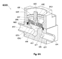
図6Aおよび図6Bは、内側流体コンジット開口部612を囲むオリフィス・リッジ618に当接する制御板640を有する、ダイヤフラムによる封止を用いた比例制御弁600の代表例を説明する図である。比例制御弁600は、第1流体コンジット610と第2流体コンジット614とを有する弁本体619を備え、第1流体コンジット610と第2流体コンジット614の各々は、弁室650へまたは弁室650から流体を連通させる。比例制御弁600は、さらに、ガスケット665によって弁本体619に封止された弁ボンネット669を備え、ボンネット669は、取り付けられた制御板640の弁室650での動きを可能にするダイヤフラム667を有する。流体の流れの制御方法は、第1流体コンジット610と流体連通している、オリフィス・リッジ618によって囲まれた内側流体コンジット開口部612を考慮するとさらに理解できる。これによって、制御板640の少なくとも一部は、オリフィス・リッジ618に近づいたり遠ざかったりすることができ、流体が制御可能に流れることができる小さなクリアランスの制御間隙(図示せず)を作る。制御可能な流体の流れは、弁室650内へ移動でき、第2流体コンジット614と流体連通している外側流体コンジット開口部616から出ることができる。この弁600の例において、駆動部(図示せず)が制御軸682に引き戻し力を加えてダイヤフラム667を撓ませることができるので、制御間隙を変更することによって、弁を通るコンダクタンスを調節する。この図6Aの説明において、弁600は、無流量状態で完全に閉じているので、制御間隙は図示していない。
6A and 6B are views illustrating a representative example of a
代表的な比例制御弁600において、ポリマー量を低減させるという目標は、金属製の制御板本体646と、ポリマー材のモールドされたインサート630とを備える制御板640を作ることによって実現される。図6Bからわかり得るように、制御板640の金属製の制御板本体646は、中央貫通孔642と、内側流体コンジット開口部612に面する側に複数のリング状の同心溝648とを有する平坦な円盤として機械仕上げすることができる。溝648によって、金属製の制御板本体646が弁座ハウジングとして機能できるようになる。これによりポリマー材インサート630を弁座ハウジングに保持でき、後述するが、より適合した少量の封止材を提供できる。制御板本体646内の同心溝648の間の残留金属649によって、モールドされたインサート630の総量が有意義に低減される。内側流体開口部612の反対側に面する円盤の平坦な背面に規定される通気孔644は、残留金属649の大部分をそのままに、十分な直径を有して溝648の間の中央に作られ、隣接する溝648の底部に通じるだけの深さを有する。説明した制御板640の製造において、ポリマー材インサート630は、既知の方法によって、制御板本体646に、直接、圧縮成形(たとえば、顆粒状のポリクロロトリフルオロエチレン(PCTFE)から始めて、熱圧影響下で重合する)されて形成されもよい。モールドプロセスの間に、ポリマー材のブリッジ634は残留金属649の一部を囲み、通気孔644を充填することになる。したがって、残留金属649を囲むポリマー材ブリッジ634は、モールドされたポリマーインサート630を金属製の制御板本体646内に固定する。図6Cは、モールドされたポリマーインサート630の斜視図を示し、モールドされたポリマーインサート630の形状を説明する便宜上、金属製の制御板本体646は図示されていない。モールドされたポリマーインサート630は、複数の環状リッジ638を有する。複数の環状リッジ638は、溝648と互いに補足しあっており、制御板本体646に規定された溝648を充填する。
In a typical
モールドされたポリマーインサート630を含む金属製の制御板本体646を備えた制御板640は、中央貫通孔642へのプレスばめによって、制御軸682およびダイヤフラム667から突き出るシャンク681に取り付けられてもよい。これに代えて、上述のモールドの前に、制御板本体646をシャンク681上に載置し、電子ビーム、レーザ、TIG、または任意の同等の溶接プロセスを用いて、中央貫通孔642における接点で互いを溶接してもよい。結果生じるわずかな溶接ビードのはみ出しは、インサート630を制御板本体646にモールドする前に、制御板本体646の表面から取り除くことができる。プロセスシーケンスの選択は、圧縮成形技術における作業者の好みによって異なるだろう。次に、良好な弁機能のために必要であれば、完成した組立て品を(たとえば、ラップ仕上げによって)最終的な仕上げにかけて平坦にすることができる。この設計手法は、さまざまなサイズおよび形状のオリフィス・リッジを有する弁本体と合わせて使用する際に特に有利である。非円形のオリフィス・リッジ構造である場合、オリフィス・リッジの最大全幅は、直径以外であってもよいと理解されるべきである。図6Aに図示した例を注意深く検討すると、オリフィス・リッジ618は円形であるが直径が非常に大きいため、同様に大きな非円形の外側流体開口部617を収容するために、ダイヤフラム667および制御板640の幾何学的中央からずれて載置されていることが明らかになるだろう。
A
代表的な比例制御弁600において使用するのに適した代替的な制御板660が図6Dに示されている。制御板660の金属製の制御板本体676は、中央貫通孔672と、内側流体コンジット開口部612に面する側に広くて浅いリング状の溝675とを有する平坦な円盤として機械仕上げすることができる。溝675によって、金属製の制御板本体676が弁座ハウジングとして機能できるようになる。これにより、ポリマー材インサート670を弁座ハウジングに保持でき、後述するが、より適合した少量の封止材を提供できる。内側流体開口部612の反対側に面する円盤の平坦な背面に規定される複数の貫通孔674は、広くて浅いリング状の溝675を貫通する。説明した制御板660の製造において、ポリマー材インサート670は、既知の方法によって、制御板本体676に、直接、(たとえば、顆粒状のPCTFEから始めて、熱圧影響下で重合する)圧縮成形されて形成されもよい。モールドプロセスの間に、ポリマー材の複数の柱673は、貫通孔674を充填することになるため、金属製の制御板本体676に規定された溝675にポリマー材を摩擦ロックする。モールドプロセスによって形成されたポリマー材インサート670の形状が図6Eに示されており、説明のための便宜上、制御板本体676は示されていない。モールドされたポリマーインサート670を含む金属製の制御板本体676を備えた制御板660は、中央貫通孔672へのプレスばめによって、または前述の別の方法によって、制御軸682およびダイヤフラム667から突き出るシャンク681に取り付けられ得る。
An
代表的な比例制御弁600において使用するのに適した別の代替的な制御板680が図6Fに示されている。制御板680の金属製の制御板本体696は、中央貫通孔692と、広くて浅いカウンターボア695と、内側流体コンジット開口部612に面する側に設けられたカウンターボア695の底部に切り込まれた複数の楔形の(ほぼ円形の扇形部分である)空洞697、698とを有する平坦な円盤として機械仕上げすることができる。カウンターボア695および複数の空洞697、698によって、金属製の制御板本体696が弁座ハウジングとして機能できるようになる。これにより、ポリマー材インサート690を弁座ハウジングに保持でき、さらに後述するが、より適合した少量の封止材を提供できる。制御板本体696の広くて浅いカウンターボア695における複数の楔形空洞697、698の間の金属は、径方向リブ部699を形成する。内側流体開口部612の反対側に面する円盤の平坦な背面に規定される通気孔691は、残留金属リブ部699の大部分をそのままに、十分な直径を有して径方向リブ部699上の中央に作られ、隣接する楔形空洞697、698の底部に通じるだけの深さを有する。内側流体開口部612の反対側に面する円盤の平坦な背面に同様に規定される複数の貫通孔694は、楔形空洞697、698の各々の底部を貫通する。説明した弁設計600の製造において、ポリマー材インサート690は、既知の方法によって、制御板本体696に、直接、(たとえば、顆粒状のPCTFEから始めて、熱圧影響下で重合する)圧縮成形されて形成されてもよい。モールドプロセスの間に、ポリマー材が貫通孔694を充填して金属の径方向リブ部699を囲み、通気孔691を充填することになる。モールドされたポリマー材は、通気孔を充填するためのブリッジ689および貫通孔694を充填するための支柱693を形成する。また、モールドされたポリマー材は、それぞれの楔形空洞697、698を充填するための、インサート690の楔部分を形成する。したがって、金属のリブ部699を囲むポリマー材は、モールドされたインサート690を金属製の制御板本体696内に固定する。モールドプロセスによって形成されたポリマー材インサート690の形状が図6Gに示されており、説明のための便宜上、制御板本体696は示されていない。モールドされたポリマーインサート690を含む金属製の制御板本体696を備えた制御板680は、中央貫通孔692へのプレスばめによって、または前述の別の方法によって、制御軸682およびダイヤフラム670から突き出るシャンク681に取り付けられ得る。
Another
図6A〜図6Gの各々において、それぞれのポリマー材インサート630、670、690は、オリフィス・リッジ618の平面状上端部に封止係合するように構成された平面状の第1面を含む。
In each of FIGS. 6A-6G, the respective polymeric inserts 630, 670, 690 include a planar first surface configured to seal and engage the planar upper end of the
図6A〜図6Gに示す特徴の具体的なサイズは、変更されてもよく、必ずしも縮尺通りに描かれているわけではないことが理解されるべきである。 It should be understood that the specific sizes of the features shown in FIGS. 6A-6G may vary and are not necessarily drawn to scale.
再び図2を参照すると、リング状インサート230は、図6A〜図6Gの構造などの特徴を保持することによって、制御板240の制御板本体246にモールドされ、制御板240の制御板本体246内に固定することができる。つまり、たとえば、リング状インサート230は、制御板本体246に規定される貫通孔に配置された柱、制御板本体246に規定される貫通孔に配置された支柱、および/または図6A〜図6Gに関連して記載したものと同様の方法で制御板本体に規定される通気孔に配置されたブリッジを有することができる。
Referring to FIG. 2 again, the ring-shaped
上述のカウンターボアおよび溝は、制御板本体に規定され得る凹部の例である。いくつかの実施形態において、インサートは、制御板本体に規定される別の種類の凹部に固定することができる。 The counterbore and groove described above are examples of recesses that may be defined in the control panel body. In some embodiments, the insert can be secured in another type of recess defined in the control panel body.
いくつかの実施形態において、保持機構を用いてインサートを1つ以上のカウンターボアおよび/または制御板本体に規定された1つ以上の溝に保持する。保持機構のいくつかの例は、インサートの外周に位置するリテーナリングと、インサートの内周に位置する内側リテーナリングならびにインサートの外周に位置する外側リテーナリングと、支柱と、柱と、ブリッジと、溶接部とを含む。その他の保持機構は可能である。本開示の実施形態は、制御板がダイヤフラムの下に配置され、ダイヤフラムに取り付けられるまたはダイヤフラムと一体形成される、ダイヤフラムに封止された弁について主に説明したが、本開示の態様は、米国特許第3,295,191号に記載されたものと同様のベローズ・シール・バルブなど、その他の種類の弁用に容易に適合できると理解されるべきである。また、本開示の実施形態は、駆動部を用いて制御板のオリフィス・リッジ封止面をオリフィス・リッジに近づけたり遠ざけたりする制御弁について説明したが、この動きは、制御板のオリフィス・リッジ封止面の端から端まで均一である必要はない。たとえば、本開示の実施形態は、米国特許公報第US2016/0138730A1号に記載の、増幅用円盤を用いてその他の方法で得られる場合よりも高いコンダクタンスを有する楔形の隙間を生じさせることができる弁ストローク増幅機構と共に容易に使用され得る。 In some embodiments, a holding mechanism is used to hold the insert in one or more counterbores and / or one or more grooves defined in the control panel body. Some examples of holding mechanisms include retainer rings located on the outer circumference of the insert, inner retainer rings located on the inner circumference of the insert, and outer retainer rings located on the outer circumference of the insert, struts, columns, bridges, and so on. Includes welded parts. Other holding mechanisms are possible. Although embodiments of the present disclosure have primarily described valves sealed in the diaphragm in which the control plate is located under the diaphragm and attached to the diaphragm or integrally formed with the diaphragm, aspects of the disclosure are described in the United States. It should be understood that it can be easily adapted for other types of valves, such as bellows seal valves similar to those described in Pat. No. 3,295,191. Further, in the embodiment of the present disclosure, a control valve for moving the orifice / ridge sealing surface of the control plate closer to or further from the orifice ridge by using a drive unit has been described, but this movement is based on the orifice ridge of the control plate. It does not have to be uniform from end to end of the sealing surface. For example, embodiments of the present disclosure are valves capable of producing wedge-shaped gaps with higher conductance than otherwise obtained using an amplification disc, as described in US Patent Publication No. US2016 / 0138730A1. It can be easily used with a stroke amplification mechanism.
図1〜図6Aの実施形態は、すべて、ダイヤフラム167、267、367、467、567、667と一体形成されたボンネット本体169、269、369、469、569、669を示すものとして表現されているが、本発明はそのように限定されないと理解されるべきである。実際に、本開示の実施形態は、1枚の金属の薄板から押抜き、打抜き、または切り出され、のちにボンネット本体に(たとえば、溶接によって)取り付けられたダイヤフラム、および、本明細書に示すように、ダイヤフラムとボンネット本体とが出発原料の1つの塊から一体形成されるものを包含する。
The embodiments of FIGS. 1 to 6A are all expressed as showing the bonnet
このように本発明の少なくとも一実施形態のいくつかの態様を説明したが、さまざまな代替例、変更例、および改良が当業者によって容易に想到されるだろうと理解されるべきである。このような代替例、変更例、および改良は、本開示の一部であり、本発明の範囲に含まれることが意図される。したがって、上述の説明および図面は、一例にすぎない。 Although some aspects of at least one embodiment of the invention have been described in this way, it should be understood that various alternatives, modifications, and improvements will be readily conceived by those skilled in the art. Such alternatives, modifications, and improvements are part of the present disclosure and are intended to be included within the scope of the invention. Therefore, the above description and drawings are merely examples.
Claims (17)
ボンネット本体と、
外周において前記ボンネット本体に封止係合された弁ダイヤフラムと、
前記弁ダイヤフラムに固定された制御軸とを備え、前記制御軸は、前記制御軸から突き出るシャンクを有し、前記弁ボンネットは、さらに、
前記シャンクに固定された弁制御板本体を備え、前記弁制御板本体は、第1硬度を有する第1材料から形成され、前記流体コンジット開口部に面するように構成された第1面と、前記弁ダイヤフラムに面する反対側の第2面とを有し、前記第2面は、前記弁ダイヤフラムに直接隣接し、前記弁制御板本体は、前記弁制御板本体の前記第1面に規定される凹部と、前記凹部内から前記弁制御板本体を貫通する複数の孔とを有し、前記弁ボンネットは、さらに、
前記第1硬度よりも軟らかい第2硬度を有する第2材料から形成され、前記流体コンジット開口部に面するように、かつ前記平面状のオリフィス・リッジに封止係合するように構成された第1面を有する弁座インサートを備え、前記弁座インサートは、前記凹部にモールドされて、前記凹部に保持されており、前記弁座インサートに形成された、前記弁制御板本体に規定される前記複数の孔内へ延在し前記複数の孔を充填して前記弁座インサートを前記弁制御板本体に固定する複数の支柱、柱、およびブリッジのうちの少なくとも1つを含み、前記弁制御板本体の前記第1面と前記弁座インサートの前記第1面とは、互いに平坦に仕上げられている、弁ボンネット。 A valve bonnet that has a fluid conduit opening surrounded by a flat orifice ridge and is used in combination with the control valve body.
With the bonnet body
A valve diaphragm sealed and engaged with the bonnet body on the outer circumference,
It comprises a control shaft fixed to the valve diaphragm, the control shaft has a shank protruding from the control shaft, and the valve bonnet further comprises a control shaft.
A valve control plate body fixed to the shank is provided, and the valve control plate body has a first surface formed of a first material having a first hardness and configured to face the fluid conduit opening. It has a second surface on the opposite side facing the valve diaphragm, the second surface is directly adjacent to the valve diaphragm, and the valve control plate body is defined as the first surface of the valve control plate body. The valve bonnet further has a recess to be formed and a plurality of holes penetrating the valve control plate body from the recess.
A second material formed from a second material having a second hardness that is softer than the first hardness and configured to face the fluid conduit opening and to seal and engage the planar orifice ridge. The valve seat insert having one surface is provided, and the valve seat insert is molded into the recess and held in the recess, and is defined in the valve control plate body formed in the valve seat insert. a plurality of struts for fixing a plurality of the extension Mashimashi the valve seat insert is filled with a plurality of holes into the hole in the valve control plate body, posts, and viewing at least Tsuo含of the bridge, said valve control A valve bonnet in which the first surface of the plate body and the first surface of the valve seat insert are finished flat with each other .
第1流体コンジット開口部で終端する第1流体コンジットと、第2流体コンジット開口部で始端する第2流体コンジットと、前記第1流体コンジット開口部を囲むオリフィス・リッジとを有する弁本体を備え、前記第1流体コンジットおよび前記第2流体コンジットの一方は、流体導入口コンジットであり、前記第1流体コンジットおよび前記第2流体コンジットの他方は、流体排出口コンジットであり、前記制御弁は、さらに、
前記弁本体に固定されたボンネット本体と、
外周において前記ボンネット本体に封止係合された弁ダイヤフラムと、
前記弁ダイヤフラムに固定された制御軸とを備え、前記制御軸は、前記制御軸から突き出るシャンクを有し、前記制御弁は、さらに、
前記シャンクに固定された弁制御板本体を備え、前記弁制御板本体は、第1硬度を有する第1材料から形成され、前記第1流体コンジット開口部に面するように構成された第1面と、前記弁ダイヤフラムに面する反対側の第2面とを有し、前記第2面は、前記弁ダイヤフラムに直接隣接し、前記弁制御板本体は、前記弁制御板本体の前記第1面に規定される凹部と、前記凹部内から前記弁制御板本体を貫通する複数の孔とを有し、前記制御弁は、さらに、
前記第1硬度よりも軟らかい第2硬度を有する第2材料から形成される弁座インサートを備え、前記弁座インサートは、前記第1流体コンジット開口部に面するように構成された、かつ前記オリフィス・リッジに封止係合するように構成された第1面を有し、前記弁座インサートは、前記凹部にモールドされており、前記弁座インサートに形成された、前記弁制御板本体に規定される前記複数の孔内へ延在し前記複数の孔を充填して前記弁座インサートを前記弁制御板本体に固定する複数の支柱、柱、およびブリッジのうちの少なくとも1つを含み、前記弁制御板本体の前記第1面と前記弁座インサートとは、互いに平坦に仕上げられている、制御弁。 It is a control valve
A valve body comprising a first fluid conduit terminating at the first fluid conduit opening, a second fluid conduit terminating at the second fluid conduit opening, and an orifice ridge surrounding the first fluid conduit opening. One of the first fluid conduit and the second fluid conduit is a fluid inlet conduit, the other of the first fluid conduit and the second fluid conduit is a fluid outlet conduit, and the control valve further comprises. ,
The bonnet body fixed to the valve body and
A valve diaphragm sealed and engaged with the bonnet body on the outer circumference,
The control shaft comprises a control shaft fixed to the valve diaphragm, the control shaft has a shank protruding from the control shaft, and the control valve further comprises a control shaft.
A first surface having a valve control plate body fixed to the shank, the valve control plate body being formed from a first material having a first hardness and facing the first fluid conduit opening. And a second surface on the opposite side facing the valve diaphragm, the second surface is directly adjacent to the valve diaphragm, and the valve control plate body is the first surface of the valve control plate body. The control valve has a recess defined in the above and a plurality of holes penetrating the valve control plate main body from the recess.
It comprises a valve seat insert formed of a second material having a second hardness that is softer than the first hardness, the valve seat insert being configured to face the first fluid conduit opening and the orifice. The valve seat insert has a first surface configured to seal and engage the ridge, the valve seat insert is molded into the recess, and is defined on the valve control plate body formed in the valve seat insert. a plurality of struts the extension to multiple holes Mashimashi by filling the plurality of holes for fixing the valve seat insert to the valve control plate body being, posts, and viewing at least Tsuo含of the bridge, A control valve in which the first surface of the valve control plate body and the valve seat insert are finished to be flat with each other .
Applications Claiming Priority (5)
| Application Number | Priority Date | Filing Date | Title |
|---|---|---|---|
| US201562190478P | 2015-07-09 | 2015-07-09 | |
| US62/190,478 | 2015-07-09 | ||
| US201662292526P | 2016-02-08 | 2016-02-08 | |
| US62/292,526 | 2016-02-08 | ||
| PCT/US2016/041263 WO2017007888A1 (en) | 2015-07-09 | 2016-07-07 | Control plate in a valve |
Publications (3)
| Publication Number | Publication Date |
|---|---|
| JP2018524529A JP2018524529A (en) | 2018-08-30 |
| JP2018524529A5 JP2018524529A5 (en) | 2019-08-15 |
| JP6778251B2 true JP6778251B2 (en) | 2020-10-28 |
Family
ID=57686071
Family Applications (1)
| Application Number | Title | Priority Date | Filing Date |
|---|---|---|---|
| JP2018500440A Active JP6778251B2 (en) | 2015-07-09 | 2016-07-07 | Control panel in the valve |
Country Status (10)
| Country | Link |
|---|---|
| US (2) | US20170009890A1 (en) |
| EP (1) | EP3320241A4 (en) |
| JP (1) | JP6778251B2 (en) |
| KR (1) | KR102339628B1 (en) |
| CN (1) | CN107850222B (en) |
| HK (1) | HK1252950A1 (en) |
| IL (1) | IL256593B (en) |
| MY (1) | MY188606A (en) |
| TW (1) | TWI698602B (en) |
| WO (1) | WO2017007888A1 (en) |
Families Citing this family (22)
| Publication number | Priority date | Publication date | Assignee | Title |
|---|---|---|---|---|
| US10391557B2 (en) | 2016-05-26 | 2019-08-27 | Kennametal Inc. | Cladded articles and applications thereof |
| US11248708B2 (en) | 2017-06-05 | 2022-02-15 | Illinois Tool Works Inc. | Control plate for a high conductance valve |
| US10364897B2 (en) | 2017-06-05 | 2019-07-30 | Vistadeltek, Llc | Control plate for a high conductance valve |
| TWI766034B (en) | 2017-06-05 | 2022-06-01 | 美商伊利諾工具工程公司 | Control plate for a high conductance valve |
| US10458553B1 (en) | 2017-06-05 | 2019-10-29 | Vistadeltek, Llc | Control plate for a high conductive valve |
| TWI803536B (en) * | 2017-11-21 | 2023-06-01 | 美商威士塔戴爾泰克有限責任公司 | Compact circular linkage for a pushing actuator |
| US10344757B1 (en) | 2018-01-19 | 2019-07-09 | Kennametal Inc. | Valve seats and valve assemblies for fluid end applications |
| JP7133945B2 (en) * | 2018-03-02 | 2022-09-09 | 株式会社堀場エステック | Fluid control valve and fluid control device |
| WO2019207644A1 (en) * | 2018-04-24 | 2019-10-31 | 株式会社ニコン | Fluid device, valve device, and detection device |
| EP3797235A1 (en) | 2018-05-22 | 2021-03-31 | Compart Systems Pte. Ltd. | Variable control orifice valve |
| US11566718B2 (en) | 2018-08-31 | 2023-01-31 | Kennametal Inc. | Valves, valve assemblies and applications thereof |
| JP6651586B1 (en) * | 2018-08-31 | 2020-02-19 | サーパス工業株式会社 | Flow control device and control method of flow control device |
| US20210347992A1 (en) | 2018-09-20 | 2021-11-11 | Blueshift Materials, Inc. | Filled composites with decreased thermal conductivity, dielectric constant, and weight |
| EP3874186A4 (en) * | 2018-11-01 | 2022-08-24 | Illinois Tool Works Inc. | Control plate for a high conductance valve |
| DE102019203906A1 (en) * | 2019-03-21 | 2020-09-24 | Brose Fahrzeugteile Se & Co. Kommanditgesellschaft, Bamberg | Carrier component with fastening area made of a fiber composite material and at least one support element locking a fastening element |
| US11236846B1 (en) * | 2019-07-11 | 2022-02-01 | Facebook Technologies, Llc | Fluidic control: using exhaust as a control mechanism |
| CN110566711B (en) * | 2019-08-30 | 2022-01-25 | 宁波方太厨具有限公司 | Water valve capable of being automatically closed after power failure of gas water heater and water heater with same |
| WO2021173379A1 (en) * | 2020-02-28 | 2021-09-02 | Cummins Filtration Inc. | Non-vented, semi-automated water drain valve system |
| WO2021217073A2 (en) | 2020-04-24 | 2021-10-28 | Blueshift Materials, Inc. | Air permeable filter material comprising a polymer aerogel |
| JP2023525573A (en) | 2020-05-15 | 2023-06-16 | ブルーシフト マテリアルズ インコーポレイテッド | Low dielectric constant low dielectric loss tangent laminate containing airgel layer |
| WO2021231998A1 (en) | 2020-05-15 | 2021-11-18 | Blueshift Materials, Inc. | High-temperature, thermally-insulative laminates including aerogel layers |
| JP2022110705A (en) * | 2021-01-19 | 2022-07-29 | 株式会社堀場エステック | Fluid control valve, fluid controller, valve body and manufacturing method for valve body |
Family Cites Families (79)
| Publication number | Priority date | Publication date | Assignee | Title |
|---|---|---|---|---|
| US2924233A (en) * | 1960-02-09 | michaels | ||
| US594895A (en) * | 1897-12-07 | Jeremiah o meara | ||
| US2595012A (en) * | 1947-04-03 | 1952-04-29 | Maytag Co | Spring biased valve seat seal |
| US3295191A (en) | 1963-03-25 | 1967-01-03 | Nupro Co | Method of constructing a bellows valve |
| US3438391A (en) * | 1964-01-13 | 1969-04-15 | Superior Valve & Fittings Co | Check valves having plastic sealing member |
| US3391901A (en) | 1964-09-30 | 1968-07-09 | Varian Associates | High vacuum leak valve |
| US3278156A (en) | 1965-12-27 | 1966-10-11 | Nuclear Products Company | Bellows valve |
| US4124676A (en) * | 1976-09-29 | 1978-11-07 | Crane Packing Co. | Mechanical bond |
| DE2821167C3 (en) | 1978-05-13 | 1981-01-15 | Lothar Dipl.-Kfm. Dipl.- Hdl. Dr. 5030 Huerth Wurzer | Membrane to keep two neighboring rooms separate |
| US4343754A (en) * | 1979-09-21 | 1982-08-10 | H-C Industries, Inc. | Process and apparatus for molding liners in container closures |
| US4606374A (en) | 1983-04-05 | 1986-08-19 | Nupro Company | Valve |
| US4582294A (en) * | 1985-04-01 | 1986-04-15 | Honeywell Inc. | Three-way solenoid valve |
| JPS6275180A (en) * | 1985-09-30 | 1987-04-07 | Motoyama Seisakusho:Kk | Metallic diaphragm valve |
| US4671490A (en) * | 1986-05-16 | 1987-06-09 | Nupro Co. | Diaphragm valve |
| US4732363A (en) | 1986-05-16 | 1988-03-22 | Nupro Company | Diaphragm valve |
| KR900003785B1 (en) * | 1986-10-12 | 1990-05-31 | 가부시기가이샤 다이와 | Bagging process and apparatus for using car mat |
| US4778640A (en) * | 1987-01-16 | 1988-10-18 | Warner-Lambert Company | Method of sequentially molding a razor cap |
| US4872638A (en) * | 1988-01-29 | 1989-10-10 | Semitool, Inc. | Slow acting fluid valve |
| JP2814378B2 (en) | 1988-06-20 | 1998-10-22 | 忠弘 大見 | Mass flow controller |
| US4964423A (en) | 1988-09-01 | 1990-10-23 | Nupro Company | Check valve |
| JPH0434275A (en) | 1990-05-26 | 1992-02-05 | Stec Kk | Normally closed type fluid control valve |
| FR2666345B1 (en) * | 1990-09-04 | 1994-10-14 | Roquette Freres | PROCESS FOR THE EXTRACTION OF MINOR FATTY COMPOUNDS CONTAINED IN MATERIAL OF ORGANIC ORIGIN. |
| FR2677425A1 (en) | 1991-06-07 | 1992-12-11 | Transfluid Sa | Metal diaphragm (membrane) for a diaphragm valve |
| DE4134430C1 (en) * | 1991-10-18 | 1993-02-11 | Carlo 6148 Heppenheim De Finzer | Simple and reliable laminar component prodn. - includes curving pre-finished, magnetically conducting metal plate during pre-finishing and forming magnetisable plastic onto plate by e.g. press moulding |
| US5279328A (en) | 1993-01-19 | 1994-01-18 | Fluoroware, Inc. | Weir valve with adjustable bypass |
| WO1996007086A1 (en) * | 1994-09-01 | 1996-03-07 | Sensarray Corporation | A temperature calibration substrate |
| US5533543A (en) * | 1995-01-19 | 1996-07-09 | Johnson Worldwide Associates, Inc. | Poppet seat for air regulating devices |
| JP3291152B2 (en) * | 1995-02-15 | 2002-06-10 | 株式会社フジキン | Diaphragm valve |
| JP3343313B2 (en) | 1995-06-30 | 2002-11-11 | 株式会社フジキン | Diaphragm valve |
| US5725007A (en) * | 1995-07-07 | 1998-03-10 | Stubbs; William L. | Valve mechanism and method for making same |
| US5722638A (en) * | 1995-10-20 | 1998-03-03 | Vemco Corporation | Valve with means to block relative rotation of parts during assembly |
| US5755428A (en) | 1995-12-19 | 1998-05-26 | Veriflow Corporation | Valve having metal-to metal dynamic seating for controlling the flow of gas for making semiconductors |
| US5730423A (en) | 1996-10-16 | 1998-03-24 | Parker-Hannifin Corporation | All metal diaphragm valve |
| US5851004A (en) | 1996-10-16 | 1998-12-22 | Parker-Hannifin Corporation | High pressure actuated metal seated diaphragm valve |
| US5927325A (en) | 1996-10-25 | 1999-07-27 | Inpod, Inc. | Microelectromechanical machined array valve |
| US6354565B1 (en) * | 1997-02-04 | 2002-03-12 | Phillip George Doust | Washer assembly for a faucet |
| US6123320A (en) | 1998-10-09 | 2000-09-26 | Swagelok Co. | Sanitary diaphragm valve |
| US6394417B1 (en) | 1998-10-09 | 2002-05-28 | Swagelok Co. | Sanitary diaphragm valve |
| US6142325A (en) * | 1998-10-19 | 2000-11-07 | Playtex Products, Inc. | Container assembly and bottom cap therefor |
| JP2000266230A (en) | 1999-03-15 | 2000-09-26 | Matsushita Electric Works Ltd | Semiconductor microvalve |
| CN1203996C (en) | 2000-07-07 | 2005-06-01 | 精工爱普生株式会社 | Ink feed unit for ink jet recorder and diaphragm valve |
| JP2002089725A (en) | 2000-09-14 | 2002-03-27 | Hamai Industries Ltd | Operation valve and diaphragm for operation valve |
| US7513483B1 (en) * | 2002-06-25 | 2009-04-07 | Blume George H | Valve body and seal assembly |
| JP3947957B2 (en) * | 2001-08-10 | 2007-07-25 | Smc株式会社 | solenoid valve |
| US20050224744A1 (en) | 2002-02-20 | 2005-10-13 | Nl Technologies, Ltd. | Circumferential sealing diaphragm valve |
| US6672561B2 (en) | 2002-03-28 | 2004-01-06 | Swagelok Company | Piston diaphragm with integral seal |
| US7040596B2 (en) * | 2002-11-29 | 2006-05-09 | Keihin Corporation | Solenoid valve for fuel cell |
| KR20050090409A (en) | 2002-12-20 | 2005-09-13 | 어플라이드 머티어리얼스, 인코포레이티드 | Micromachined intergrated fluid delivery system |
| US7021330B2 (en) | 2003-06-26 | 2006-04-04 | Planar Systems, Inc. | Diaphragm valve with reliability enhancements for atomic layer deposition |
| WO2005038320A2 (en) * | 2003-10-17 | 2005-04-28 | Sundew Technologies, Llc | Fail safe pneumatically actuated valve |
| US7004447B2 (en) | 2003-11-17 | 2006-02-28 | Scott Christopher Meyers | Torque sensitive sanitary diaphragm valves for use in the pharmaceutical industry and methods related thereto |
| ITBS20040074A1 (en) | 2004-06-25 | 2004-09-25 | Ratti Giampietro & C S N C | INTERCEPTING DEVICE OF A FLUID |
| JP2006090386A (en) | 2004-09-22 | 2006-04-06 | Kitz Sct:Kk | Diaphragm valve |
| JP2006153218A (en) * | 2004-11-30 | 2006-06-15 | Keihin Corp | Solenoid valve for fuel cell |
| WO2006083783A1 (en) * | 2005-01-31 | 2006-08-10 | Swagelok Company | Flow control device |
| JP2006258135A (en) * | 2005-03-15 | 2006-09-28 | Denso Corp | Solenoid valve |
| WO2007145732A2 (en) * | 2006-05-04 | 2007-12-21 | Csp Technologies, Inc. | Injection molding process for molding mechanical interlocks between molded components |
| WO2007149076A1 (en) | 2006-06-19 | 2007-12-27 | Norgren, Inc. | A fluid control device with a non-circular flow area |
| JP2008075827A (en) * | 2006-09-25 | 2008-04-03 | Denso Corp | Fluid control valve |
| DE102007014282A1 (en) | 2007-03-19 | 2008-10-02 | Südmo Holding GmbH | Valve for separating product media in pipelines of a product-carrying system |
| GB0706240D0 (en) * | 2007-03-30 | 2007-05-09 | Concept 2 Manufacture Design O | A valve means for gas control devices |
| JP4971030B2 (en) | 2007-05-21 | 2012-07-11 | シーケーディ株式会社 | Fluid control valve |
| FR2919610B1 (en) | 2007-08-02 | 2009-10-16 | Sanofi Aventis Sa | TRICYCLIC N-HETEROARYL-CARBOXAMIDE DERIVATIVES, THEIR PREPARATION AND THEIR THERAPEUTIC USE |
| CN101680559B (en) * | 2007-12-07 | 2012-04-18 | 日酸田中株式会社 | Pressure regulation valve |
| JP5141301B2 (en) * | 2008-02-29 | 2013-02-13 | アイシン精機株式会社 | Valve device and method for manufacturing valve device |
| CN101328980A (en) * | 2008-07-30 | 2008-12-24 | 玉环县华龙阀门有限公司 | Valve plate of gate valve and method for manufacturing the same |
| JP5544868B2 (en) * | 2009-12-22 | 2014-07-09 | アイシン精機株式会社 | Gas shut-off valve for fuel cell |
| JP5565856B2 (en) | 2010-03-24 | 2014-08-06 | セイコーインスツル株式会社 | Diaphragm, diaphragm valve, and method for manufacturing diaphragm |
| GB2492955A (en) | 2011-07-13 | 2013-01-23 | Oxford Nanopore Tech Ltd | One way valve |
| FR2991423B1 (en) | 2012-05-30 | 2015-05-01 | Coutier Moulage Gen Ind | NON-RETURN VALVE OF THE MEMBRANE TYPE |
| DE102012019193A1 (en) * | 2012-09-24 | 2014-03-27 | Hydac Electronic Gmbh | Valve |
| US20140084202A1 (en) * | 2012-09-27 | 2014-03-27 | Emerson Process Management Regulator Technologies, Inc. | Seal disk with a plurality of hardnesses |
| JP6081800B2 (en) | 2013-01-07 | 2017-02-15 | 株式会社堀場エステック | Fluid control valve and mass flow controller |
| JP6141663B2 (en) | 2013-03-27 | 2017-06-07 | 株式会社堀場エステック | Fluid control valve |
| JP6111862B2 (en) | 2013-05-24 | 2017-04-12 | 日立金属株式会社 | Flow control valve and mass flow controller using the same |
| GB2517451A (en) * | 2013-08-20 | 2015-02-25 | Seetru Ltd | A valve sealing arrangement |
| WO2015035045A2 (en) * | 2013-09-04 | 2015-03-12 | Kim Ngoc Vu | Interlace lifting mechanism |
| JP5891536B2 (en) | 2013-11-11 | 2016-03-23 | Smc株式会社 | Valve device |
| WO2016081191A1 (en) | 2014-11-19 | 2016-05-26 | Vistadel Tek, Llc | Valve stroke amplification mechanism assembly |
-
2016
- 2016-07-07 US US15/204,245 patent/US20170009890A1/en not_active Abandoned
- 2016-07-07 WO PCT/US2016/041263 patent/WO2017007888A1/en active Application Filing
- 2016-07-07 EP EP16821954.1A patent/EP3320241A4/en active Pending
- 2016-07-07 CN CN201680040357.XA patent/CN107850222B/en active Active
- 2016-07-07 TW TW105121627A patent/TWI698602B/en active
- 2016-07-07 JP JP2018500440A patent/JP6778251B2/en active Active
- 2016-07-07 MY MYPI2018000036A patent/MY188606A/en unknown
- 2016-07-07 KR KR1020187003610A patent/KR102339628B1/en active IP Right Grant
-
2017
- 2017-12-26 IL IL256593A patent/IL256593B/en unknown
-
2018
- 2018-09-26 HK HK18112306.4A patent/HK1252950A1/en unknown
- 2018-12-06 US US16/211,957 patent/US10527177B2/en active Active
Also Published As
| Publication number | Publication date |
|---|---|
| IL256593A (en) | 2018-02-28 |
| JP2018524529A (en) | 2018-08-30 |
| CN107850222B (en) | 2022-11-01 |
| IL256593B (en) | 2021-12-01 |
| US10527177B2 (en) | 2020-01-07 |
| EP3320241A1 (en) | 2018-05-16 |
| EP3320241A4 (en) | 2018-07-18 |
| US20190170261A1 (en) | 2019-06-06 |
| KR20180020302A (en) | 2018-02-27 |
| TW201704664A (en) | 2017-02-01 |
| CN107850222A (en) | 2018-03-27 |
| TWI698602B (en) | 2020-07-11 |
| US20170009890A1 (en) | 2017-01-12 |
| MY188606A (en) | 2021-12-22 |
| HK1252950A1 (en) | 2019-06-06 |
| KR102339628B1 (en) | 2021-12-14 |
| WO2017007888A1 (en) | 2017-01-12 |
Similar Documents
| Publication | Publication Date | Title |
|---|---|---|
| JP6778251B2 (en) | Control panel in the valve | |
| US10941867B2 (en) | High conductance valve for fluids and vapors | |
| KR102188285B1 (en) | Built-in orifice valve and pressure type flow control device | |
| JP4879285B2 (en) | Valve with repulsive diaphragm | |
| US8695636B2 (en) | One piece double membrane diaphragm valve | |
| US11885420B2 (en) | Control plate for a high conductance valve | |
| MX2008011600A (en) | A rocker type diaphragm valve. | |
| JP2020522654A (en) | Control plate for high conductance valves | |
| US10364897B2 (en) | Control plate for a high conductance valve | |
| US10458553B1 (en) | Control plate for a high conductive valve | |
| JP7147062B2 (en) | Control plate for high conductance valves | |
| JP2020118245A (en) | Spring structure | |
| JP2020165476A (en) | Diaphragm valve |
Legal Events
| Date | Code | Title | Description |
|---|---|---|---|
| A521 | Request for written amendment filed |
Free format text: JAPANESE INTERMEDIATE CODE: A523 Effective date: 20190705 |
|
| A621 | Written request for application examination |
Free format text: JAPANESE INTERMEDIATE CODE: A621 Effective date: 20190705 |
|
| A977 | Report on retrieval |
Free format text: JAPANESE INTERMEDIATE CODE: A971007 Effective date: 20200622 |
|
| A131 | Notification of reasons for refusal |
Free format text: JAPANESE INTERMEDIATE CODE: A131 Effective date: 20200630 |
|
| A521 | Request for written amendment filed |
Free format text: JAPANESE INTERMEDIATE CODE: A523 Effective date: 20200909 |
|
| TRDD | Decision of grant or rejection written | ||
| A01 | Written decision to grant a patent or to grant a registration (utility model) |
Free format text: JAPANESE INTERMEDIATE CODE: A01 Effective date: 20201006 |
|
| A61 | First payment of annual fees (during grant procedure) |
Free format text: JAPANESE INTERMEDIATE CODE: A61 Effective date: 20201009 |
|
| R150 | Certificate of patent or registration of utility model |
Ref document number: 6778251 Country of ref document: JP Free format text: JAPANESE INTERMEDIATE CODE: R150 |
|
| R250 | Receipt of annual fees |
Free format text: JAPANESE INTERMEDIATE CODE: R250 |