EP3193036A1 - Disc brake device and disc brake for railway - Google Patents
Disc brake device and disc brake for railway Download PDFInfo
- Publication number
- EP3193036A1 EP3193036A1 EP15833883.0A EP15833883A EP3193036A1 EP 3193036 A1 EP3193036 A1 EP 3193036A1 EP 15833883 A EP15833883 A EP 15833883A EP 3193036 A1 EP3193036 A1 EP 3193036A1
- Authority
- EP
- European Patent Office
- Prior art keywords
- holding member
- pressure plate
- pad holding
- disc
- pad
- Prior art date
- Legal status (The legal status is an assumption and is not a legal conclusion. Google has not performed a legal analysis and makes no representation as to the accuracy of the status listed.)
- Granted
Links
Images







Classifications
-
- B—PERFORMING OPERATIONS; TRANSPORTING
- B61—RAILWAYS
- B61H—BRAKES OR OTHER RETARDING DEVICES SPECIALLY ADAPTED FOR RAIL VEHICLES; ARRANGEMENT OR DISPOSITION THEREOF IN RAIL VEHICLES
- B61H5/00—Applications or arrangements of brakes with substantially radial braking surfaces pressed together in axial direction, e.g. disc brakes
-
- F—MECHANICAL ENGINEERING; LIGHTING; HEATING; WEAPONS; BLASTING
- F16—ENGINEERING ELEMENTS AND UNITS; GENERAL MEASURES FOR PRODUCING AND MAINTAINING EFFECTIVE FUNCTIONING OF MACHINES OR INSTALLATIONS; THERMAL INSULATION IN GENERAL
- F16D—COUPLINGS FOR TRANSMITTING ROTATION; CLUTCHES; BRAKES
- F16D55/00—Brakes with substantially-radial braking surfaces pressed together in axial direction, e.g. disc brakes
- F16D55/02—Brakes with substantially-radial braking surfaces pressed together in axial direction, e.g. disc brakes with axially-movable discs or pads pressed against axially-located rotating members
- F16D55/22—Brakes with substantially-radial braking surfaces pressed together in axial direction, e.g. disc brakes with axially-movable discs or pads pressed against axially-located rotating members by clamping an axially-located rotating disc between movable braking members, e.g. movable brake discs or brake pads
- F16D55/224—Brakes with substantially-radial braking surfaces pressed together in axial direction, e.g. disc brakes with axially-movable discs or pads pressed against axially-located rotating members by clamping an axially-located rotating disc between movable braking members, e.g. movable brake discs or brake pads with a common actuating member for the braking members
- F16D55/2245—Brakes with substantially-radial braking surfaces pressed together in axial direction, e.g. disc brakes with axially-movable discs or pads pressed against axially-located rotating members by clamping an axially-located rotating disc between movable braking members, e.g. movable brake discs or brake pads with a common actuating member for the braking members in which the common actuating member acts on two levers carrying the braking members, e.g. tong-type brakes
-
- F—MECHANICAL ENGINEERING; LIGHTING; HEATING; WEAPONS; BLASTING
- F16—ENGINEERING ELEMENTS AND UNITS; GENERAL MEASURES FOR PRODUCING AND MAINTAINING EFFECTIVE FUNCTIONING OF MACHINES OR INSTALLATIONS; THERMAL INSULATION IN GENERAL
- F16D—COUPLINGS FOR TRANSMITTING ROTATION; CLUTCHES; BRAKES
- F16D55/00—Brakes with substantially-radial braking surfaces pressed together in axial direction, e.g. disc brakes
- F16D55/02—Brakes with substantially-radial braking surfaces pressed together in axial direction, e.g. disc brakes with axially-movable discs or pads pressed against axially-located rotating members
- F16D55/22—Brakes with substantially-radial braking surfaces pressed together in axial direction, e.g. disc brakes with axially-movable discs or pads pressed against axially-located rotating members by clamping an axially-located rotating disc between movable braking members, e.g. movable brake discs or brake pads
- F16D55/224—Brakes with substantially-radial braking surfaces pressed together in axial direction, e.g. disc brakes with axially-movable discs or pads pressed against axially-located rotating members by clamping an axially-located rotating disc between movable braking members, e.g. movable brake discs or brake pads with a common actuating member for the braking members
- F16D55/225—Brakes with substantially-radial braking surfaces pressed together in axial direction, e.g. disc brakes with axially-movable discs or pads pressed against axially-located rotating members by clamping an axially-located rotating disc between movable braking members, e.g. movable brake discs or brake pads with a common actuating member for the braking members the braking members being brake pads
- F16D55/2255—Brakes with substantially-radial braking surfaces pressed together in axial direction, e.g. disc brakes with axially-movable discs or pads pressed against axially-located rotating members by clamping an axially-located rotating disc between movable braking members, e.g. movable brake discs or brake pads with a common actuating member for the braking members the braking members being brake pads in which the common actuating member is pivoted
-
- F—MECHANICAL ENGINEERING; LIGHTING; HEATING; WEAPONS; BLASTING
- F16—ENGINEERING ELEMENTS AND UNITS; GENERAL MEASURES FOR PRODUCING AND MAINTAINING EFFECTIVE FUNCTIONING OF MACHINES OR INSTALLATIONS; THERMAL INSULATION IN GENERAL
- F16D—COUPLINGS FOR TRANSMITTING ROTATION; CLUTCHES; BRAKES
- F16D65/00—Parts or details
- F16D65/005—Components of axially engaging brakes not otherwise provided for
- F16D65/0068—Brake calipers
-
- F—MECHANICAL ENGINEERING; LIGHTING; HEATING; WEAPONS; BLASTING
- F16—ENGINEERING ELEMENTS AND UNITS; GENERAL MEASURES FOR PRODUCING AND MAINTAINING EFFECTIVE FUNCTIONING OF MACHINES OR INSTALLATIONS; THERMAL INSULATION IN GENERAL
- F16D—COUPLINGS FOR TRANSMITTING ROTATION; CLUTCHES; BRAKES
- F16D65/00—Parts or details
- F16D65/02—Braking members; Mounting thereof
-
- F—MECHANICAL ENGINEERING; LIGHTING; HEATING; WEAPONS; BLASTING
- F16—ENGINEERING ELEMENTS AND UNITS; GENERAL MEASURES FOR PRODUCING AND MAINTAINING EFFECTIVE FUNCTIONING OF MACHINES OR INSTALLATIONS; THERMAL INSULATION IN GENERAL
- F16D—COUPLINGS FOR TRANSMITTING ROTATION; CLUTCHES; BRAKES
- F16D65/00—Parts or details
- F16D65/02—Braking members; Mounting thereof
- F16D65/04—Bands, shoes or pads; Pivots or supporting members therefor
- F16D65/092—Bands, shoes or pads; Pivots or supporting members therefor for axially-engaging brakes, e.g. disc brakes
- F16D65/095—Pivots or supporting members therefor
-
- F—MECHANICAL ENGINEERING; LIGHTING; HEATING; WEAPONS; BLASTING
- F16—ENGINEERING ELEMENTS AND UNITS; GENERAL MEASURES FOR PRODUCING AND MAINTAINING EFFECTIVE FUNCTIONING OF MACHINES OR INSTALLATIONS; THERMAL INSULATION IN GENERAL
- F16D—COUPLINGS FOR TRANSMITTING ROTATION; CLUTCHES; BRAKES
- F16D65/00—Parts or details
- F16D65/02—Braking members; Mounting thereof
- F16D65/04—Bands, shoes or pads; Pivots or supporting members therefor
- F16D65/092—Bands, shoes or pads; Pivots or supporting members therefor for axially-engaging brakes, e.g. disc brakes
- F16D65/095—Pivots or supporting members therefor
- F16D65/097—Resilient means interposed between pads and supporting members or other brake parts
- F16D65/0973—Resilient means interposed between pads and supporting members or other brake parts not subjected to brake forces
- F16D65/0974—Resilient means interposed between pads and supporting members or other brake parts not subjected to brake forces acting on or in the vicinity of the pad rim in a direction substantially transverse to the brake disc axis
- F16D65/0977—Springs made from sheet metal
- F16D65/0978—Springs made from sheet metal acting on one pad only
-
- F—MECHANICAL ENGINEERING; LIGHTING; HEATING; WEAPONS; BLASTING
- F16—ENGINEERING ELEMENTS AND UNITS; GENERAL MEASURES FOR PRODUCING AND MAINTAINING EFFECTIVE FUNCTIONING OF MACHINES OR INSTALLATIONS; THERMAL INSULATION IN GENERAL
- F16D—COUPLINGS FOR TRANSMITTING ROTATION; CLUTCHES; BRAKES
- F16D69/00—Friction linings; Attachment thereof; Selection of coacting friction substances or surfaces
- F16D69/04—Attachment of linings
- F16D69/0408—Attachment of linings specially adapted for plane linings
-
- F—MECHANICAL ENGINEERING; LIGHTING; HEATING; WEAPONS; BLASTING
- F16—ENGINEERING ELEMENTS AND UNITS; GENERAL MEASURES FOR PRODUCING AND MAINTAINING EFFECTIVE FUNCTIONING OF MACHINES OR INSTALLATIONS; THERMAL INSULATION IN GENERAL
- F16F—SPRINGS; SHOCK-ABSORBERS; MEANS FOR DAMPING VIBRATION
- F16F1/00—Springs
- F16F1/02—Springs made of steel or other material having low internal friction; Wound, torsion, leaf, cup, ring or the like springs, the material of the spring not being relevant
- F16F1/18—Leaf springs
-
- F—MECHANICAL ENGINEERING; LIGHTING; HEATING; WEAPONS; BLASTING
- F16—ENGINEERING ELEMENTS AND UNITS; GENERAL MEASURES FOR PRODUCING AND MAINTAINING EFFECTIVE FUNCTIONING OF MACHINES OR INSTALLATIONS; THERMAL INSULATION IN GENERAL
- F16D—COUPLINGS FOR TRANSMITTING ROTATION; CLUTCHES; BRAKES
- F16D69/00—Friction linings; Attachment thereof; Selection of coacting friction substances or surfaces
- F16D2069/004—Profiled friction surfaces, e.g. grooves, dimples
-
- F—MECHANICAL ENGINEERING; LIGHTING; HEATING; WEAPONS; BLASTING
- F16—ENGINEERING ELEMENTS AND UNITS; GENERAL MEASURES FOR PRODUCING AND MAINTAINING EFFECTIVE FUNCTIONING OF MACHINES OR INSTALLATIONS; THERMAL INSULATION IN GENERAL
- F16D—COUPLINGS FOR TRANSMITTING ROTATION; CLUTCHES; BRAKES
- F16D2125/00—Components of actuators
- F16D2125/18—Mechanical mechanisms
- F16D2125/58—Mechanical mechanisms transmitting linear movement
- F16D2125/64—Levers
- F16D2125/645—Levers with variable leverage, e.g. movable fulcrum
Definitions
- the pressure plate is fixedly placed on the moving shaft in a direction in which the abutment surface of the pressure plate becomes parallel to the disc rotor and is supported so as not only to rotate but also to move back and forth thereon.
- the actuator 17 includes a motor gear unit which is made up of an electric motor and a speed reduction mechanism, a hydraulic driving mechanism or an pneumatic driving mechanism, a servo mechanism and a pair of rods 31.
- the rods 31 are reciprocated via the servo mechanism as a result of the motor gear unit or the like being driven.
- the pair of rods 31 are connected to one of the swing ends 33 of the pair of brake arms 15.
- the actuator 17 causes one of the swing ends 33 of the pair of brake arms 15 to move away from each other via reciprocating rods 31.
- the other of the swing ends 35 of the pair of brake arms 15 are caused to move towards each other so as to narrow a gap therebetween.
- the lining surfaces 41 of the pads 39 will be described as being pressed against both side surfaces of the disc rotor which is assembled to the wheel 43 to execute a braking operation (refer to Fig. 7 ).
- the disc brake apparatus 11 may configured so that a disc rotor (whose illustration is omitted) provided separately from the wheel 43 is press held by the lining surfaces 41 of the pads 39 to brake the wheel 43.
- the parallelism maintaining control mechanism 23 is configured to press the lining surfaces 41 of the pads 39 which are held on the pad holding member 19 against a side surface of the wheel 43 (the disc rotor) in parallel and has a pressure plate 49, a link arm 47 and a spring member 45.
- the connecting shaft of the invention is made up of at least one of shafts which support rotatably the joint members.
- the joint members are made up of the first joint member 65 and the second joint member 67, there is provided one connecting shaft, which is the connecting shaft 63, for connecting these joint members together.
- Sliding bushes 69 are interposed individually in a portion where the fixing shaft 61 penetrates the first joint member 65 and a portion where the connecting shaft 63 penetrates the first joint member 65.
- the fixing shaft 61, the connecting shaft 63 and the moving shaft 57 of the link arm 47 are all disposed parallel to the side surface of the wheel 43 (the disc rotor) and directed in the same direction (a direction which is at right angles to the up-and-down direction).
- the moving shaft 57 can move in a direction in which the moving shaft 57 moves towards or away from the side surface of the wheel 43 (the disc rotor) and in the up-and-down direction (the direction which follows the axes of the holder shafts 37) while being kept parallel to the side surface at all times.
- the abutment surface 71 of the pressure plate 49 is guided so as to move relative to the pad holding member 19, the abutment surface 71 of the pressure plate 49 can be caused to move smoothly relative to the pad holding member 19.
- the pads 39 are allowed to follow the inclined wheel 43 (disc rotor), whereby the eccentric wear and drag can be prevented from being generated in the pads 39.
- the moving shaft inserting hole 93 in the pad holding member 19A is fitted on the moving shaft 57 in a direction in which the lining surfaces 41 of the pads 39 become parallel to the wheel 43 (the disc rotor) in such a way that the moving shaft inserting hole 93 rotates and moves back and forth on the moving shaft 57.
- the invention is not limited to the embodiments that have been described heretofore and hence can be modified or improved as required.
- the materials, shapes, dimensions, numbers, arranging positions and the like of the constituent elements described in the embodiments are arbitrary and hence are not limited thereto, provided that those elements can achieve the invention.
Landscapes
- Engineering & Computer Science (AREA)
- General Engineering & Computer Science (AREA)
- Mechanical Engineering (AREA)
- Braking Arrangements (AREA)
- Springs (AREA)
Abstract
Description
- The present invention relates to a disc brake apparatus and a disc brake for a railway vehicle.
- There are known disc brake apparatuses in which a braking force is produced by pressing pads against a disc rotor (refer to Patent Literature 1).
- As shown in
Fig. 13 , adisc brake caliper 501 for a railway vehicle disclosed inPatent Literature 1 includesbrake pad holders 505 which are suspended to lie on both sides of a brake disc (not shown) to be braked and which move only on planes which are normal to a substantially horizontal center line of the caliper.Replaceable brake pads 509 are provided individually on thebrake pad holders 505 so as to be brought into frictional engagement with the brake disc. - The
disc brake caliper 501 has anattachment bracket 503, and theattachment bracket 503 is attached to an undercarriage or bogie of a railway vehicle. Theattachment bracket 503 makes up a three-point support structure and bifurcates towards the front.Suspension links 507 are rotatably suspended at respective front end portions of the bifurcatedattachment bracket 503. Rotating shafts of thesuspension links 507 are parallel to the center line of the caliper and the brake disc. Thesuspension links 507 are connected rotatably to the correspondingbrake pad holders 505 at lower end portions thereof. Rotating shafts of thesuspension links 507 are parallel to the rotating shafts described above and therefore are parallel to the center line of the caliper. -
Upper levers 515 andlower levers 517, which correspond to sides of thedisc brake caliper 501, are provided at a central portion of abridge component 511 which is connected to theattachment bracket 503 by an elastic connectingportion 513, Ashaft 519 is provided between each of the pairs ofupper lever 515 andlower lever 517. Front end portions of thelevers 515 and thelevers 517 are attached rotatably to thebrake pad holders 505 so that thelevers 515 and thelevers 517 an rotate about rotating shafts which are normal to the center line of the caliper. - A
braking unit 521 is connected rotatably to rear end portions of thelevers 515 and thelevers 517 in a suspended fashion. When compressed air is taken into a brake cylinder, thebraking unit 521 pushes the rear end portions of thelevers 515 and thelevers 517 so that the rear end portions move laterally away from each other, whereby the front end portions of thelevers 515 and thelevers 517 cooperate to cause thebrake pads 509 to apply a braking force to the brake disc. - In the
disc brake caliper 501, thebrake pad holders 505 are guided in a fixed fashion relative to the planes which are normal to the center of the caliper by thesuspension links 507 of thebrake pad holders 505, while all the other constituent elements of the caliper are guided in an elastic fashion in every direction by the elastic connectingportion 513 provided between theattachment bracket 503 and thebridge component 511. - By adopting this configuration, the
brake pad holders 505 are suspended so as to move only on the planes which are normal to the center of the caliper, so that thebrake pad holders 505 are equally pressed against the brake disc when the brake is applied. Namely, thedisc brake caliper 501 is configured so that parallelism between thebrake pad holders 505 is maintained by thesuspension links 507 which make up a parallelism maintaining control mechanism even though theattachment bracket 503 and thelevers 515 and thelevers 517, which are supported on theattachment bracket 503. are caused to swing laterally. - [Patent Literature 1]
JP-A-2009-536119 - In the conventional
disc brake caliper 501, however, thesuspension links 507 which are provided at the upper potion to make up the parallelism maintaining control mechanisms are enlarged in size because thesuspension links 507 bear the braking torque. Then, there has been desired a disc brake apparatus including parallelism maintaining control mechanisms which are light in weight and compact in size. - The invention has been made in view of the situations, and an object thereof is to provide a disc brake apparatus and a disc brake for a railway vehicle which can allow postures of pads to be maintained parallel to a disc rotor by means of parallelism maintaining control mechanisms which are compact in size.
- The above object of the invention would be attained by the following configurations.
- (1) A disc brake apparatus including:
- a base member;
- a pair of brake arms pivotally supported to be swingable with respect to the base member;
- an actuator connected to one of swing ends of each of the pair of brake arms so as to move the brake arms away from each other;
- a pad holding member pivotally supported at the other of the swing ends of the each of the pair of brake arms so as to freely turn; and
- a parallelism maintaining control mechanism configured to press a lining surface of a pad held on the pad holding member to a disc rotor in a parallel fashion.
- The parallelism maintaining control mechanism is disposed near a center along a swing axis of the each of the brake arms so as to connect the base member and the pad holding member together.
- According to the disc brake apparatus configured as described under (1) above, since the parallelism maintaining control mechanism is disposed near the center along the oscillating center axis of the brake arm and no braking torque is inputted directly into the parallelism maintaining control mechanism, it is possible to realize the parallelism maintaining control mechanism which is small in size and light in weight.
-
- (2) A disc brake apparatus including:
- a base member;
- a pair of brake arms pivotally supported to be swingable with respect to the base member;
- an actuator connected to one of swing ends of each of the pair of brake arms so as to move the brake arms away from each other;
- a pad holding member pivotally supported at the other of the swing ends of the each of the pair of brake arms so as to freely turn; and
- a parallelism maintaining control mechanism configured to press a lining surface of a pad held on the pad holding member to a disc rotor in a parallel fashion,
- The parallelism maintaining control mechanism includes a link arm which comprises:
- a fixing shaft projecting from the base member so as to be parallel to a side surface of the disc rotor;
- a moving shaft disposed parallel to the fixing shaft and fitted in a moving shaft insertion hole in the pad holding member to be rotatable and movable back and forth;
- at least two joint members which connect the fixing shaft and the moving shaft together in parallel; and
- at least one connecting shaft which supports the joint members so at to be rotatable with respect to each other.
- According to the disc brake apparatus configured as described under (2) above, the pad holding member is guided by the parallelism maintaining control mechanism so that the lining surface of the pad held thereby becomes parallel to the disc rotor. The parallelism maintaining control mechanisms each have the link arm which brings the pad into press contact with the disc rotor in a parallel fashion. The link arms are each made up of the fixing shaft, the moving shaft, at least two of the joint members and the connecting shaft. The moving shaft is allowed to move not only in the up-and-down direction but also in the directions in which the moving shaft moves towards and away from the disc rotor while being maintained parallel relative to the disc rotor by the link arm.
- The moving shaft inserting hole in the pad holding member is fitted on the moving shaft in the direction in which the lining surface of the pad becomes parallel to the disc rotor in such a way that the moving shaft rotates and moves back and forth in the moving shaft inserting hole.
- By adopting this configuration, the parallelism maintaining control mechanism can maintain the posture of the pad holding member so that the lining surface of the pad becomes parallel to the disc rotor. The link arm has the two or more joint members. By adopting this configuration, when compared with the conventional suspension link which is one long joint member, the individual joint members can be made short, whereby even with the compact construction, the link arm can allow the moving shaft to translate in a horizontal direction relative to the fixing shaft.
- Consequently, it is possible to provide the disc brake apparatus which includes the compact parallelism maintaining control mechanisms.
-
- (3) A disc brake apparatus including:
- a base member;
- a pair of brake arms pivotally supported to be swingable with respect to the base member;
- an actuator connected to one of swing ends of each of the pair of brake arms so as to move the brake arms away from each other;
- a pad holding member pivotally supported at the other of the swing ends of the each of the pair of brake arms so as to freely turn; and
- a parallelism maintaining control mechanism configured to press a lining surface of a pad held on the pad holding member to a disc rotor in a parallel fashion.
- The parallelism maintaining control mechanism includes:
- a pressure plate which is brought into abutment with the pad holding member;
- a link arm including:
- a fixing shaft projecting from the base member so as to be parallel to a side surface of the disc rotor;
- a moving shaft which is disposed parallel to the fixing shaft and which supports the pressure plate so as to be rotatable and movable back and forth;
- at least two joint members which connect the fixing shaft and the moving shaft together in parallel; and
- at least one connecting shaft which supports the joint members so at to be rotatable with respect to each other; and
- a spring member which elastically biases an abutment surface of the pressure plate in a direction in which the abutment surface is pressed against the pad holding member.
- According to the disc brake apparatus configured as described under (3) above, the pad holding member is guided by the parallelism maintaining control mechanism so that the lining surface of the pad held thereby becomes parallel to the disc rotor. The parallelism maintaining control mechanisms each have the pressure plate and the link arm which bring the pad into press contact with the disc rotor in a parallel fashion. The link arms are each made up of the fixing shaft, the moving shaft, at least two of the joint members and the connecting shaft. The moving shaft is allowed to move not only in the up-and-down direction but also in the directions in which the moving shaft moves towards and away from the disc rotor while being maintained parallel relative to the disc rotor by the link arm.
- The pressure plate is fixedly placed on the moving shaft in a direction in which the abutment surface of the pressure plate becomes parallel to the disc rotor and is supported so as not only to rotate but also to move back and forth thereon.
- The spring member is fixed to the pad holding member, and the spring member elastically biases the abutment surface of the pressure plate in the direction in which the abutment surface is pressed against the pad holding member. By adopting this configuration, in a normal state where a load of a certain magnitude or greater is not applied to the parallelism maintaining control mechanism, the posture of the pad holding member which is tightly secured to the abutment surface of the pressure plate is maintained so that the lining surface of the pad becomes parallel to the disc rotor. The link arm has the two or more joint members. By adopting this configuration, when compared with the conventional suspension link which is one long joint member, the individual joint members can be made short, whereby even with the compact construction, the link arm can allow the moving shaft which pivotally supports the pressure plate to translate in a horizontal direction relative to the fixing shaft.
- Consequently, it is possible to provide the disc brake apparatus which includes the compact parallelism maintaining control mechanisms.
- On the other hand, when a load of a certain degree or greater is applied to the pad holding member via the pad whereby a moment load of the pad holding member is transmitted to the abutment surface of the pressure plate, the pressure plate is allowed to move relative to the pad holding member against the biasing force of the spring member.
- The abutment surface of the pressure plate and the pad holding member are released from the tightly secured state, thereby making it possible to generate a gap therebetween. Consequently, the pad holding member (the pad) can change its angle along the disc rotor, whereby the lining surface of the pad can be pressed against the disc rotor uniformly. In addition, since the abutment surface of the pressure plate can move relative to the pad holding member, an excessive load that would otherwise be applied to the link arm is eliminated.
-
- (4) The disc brake apparatus configured as described under (3) above, in which a pair of engagement holes whose center axes extend along an up-and-down direction are depressed into an upper and lower surfaces of the pressure plate which are at right angles to the abutment surface thereof, and wherein locking projecting portions which lock individually the engagement holes to the pad holding member are fitted individually loosely in the holes so as to generate a gap which permits a predetermined inclination of the locking projecting portions.
- According to the disc brake apparatus configured as described under (4) above, the pressure plate can be assembled to the pad holding member by locking the engagement holes of the pressure plate by the locking projecting portions of the pad holding member, thereby assembly becomes easy. Since the locking projecting portions are individually loosely fitted in the engagement holes of the pressure plate so as to generate the gap which permits the predetermined inclination of the locking projecting portion, there is no such situation that the relative movement of the pressure plate to the pad holding member is interrupted.
-
- (5) The disc brake apparatus configured as described under (3) or (4) above, in which the abutment surface of the pressure plate is guided so as to move relative to the pad holding member.
- According to the disc brake apparatus configured as described (5) above, the abutment surface of the pressure plate is allowed to move smoothly relative to the pad holding member.
-
- (6) The disc brake apparatus configured as described under any one of (3) to (5) above, in which the fixing shaft is fixed to each of bearing bosses which support the pair of brake arms so as to be swingable relative to the base member, and wherein the pressure plate is pressed against a longitudinally middle portion of the pad holding member along a turning shaft thereof.
- According to the disc brake apparatus configured as described under (6) above, the parallelism maintaining control mechanism is situated so as to connect the longitudinally middle portion of the pad holding member along the turning shaft thereof which lies near a center of the pad and the bearing boss of the base member together and is configured light in weight and small in size.
-
- (7) The disc brake apparatus configured as described under any one of (3) to (6) above, in which the spring member is formed of a plate spring which covers an outer surface of the pressure plate.
- According to the disc brake apparatus configured as described under (7) above, the pressure plate is covered by the spring member to thereby be protected against damage made by a piece of flying stone. In addition, since the spring member is disposed on a mechanism surface side (an opposite side to a side facing the disc rotor) of the parallelism maintaining control mechanism which is visible from an exterior portion, it is possible to easily verify how the spring member is attached to the parallelism maintaining control mechanism or whether or not the spring member is damaged in a visual fashion. Additionally, through holes are formed in support plate portions which are formed at an upper and lower edges of the spring member which is formed of the plate spring, and the locking projecting portions of the pad holding members which lock the engagement hole of the pressure plate are put through the through holes, whereby the spring member is supported on the pad holding member.
-
- (8) A disc brake for a railway vehicle including the disc brake apparatus according to any one of (1) to (7).
- According to the disc brake for a railway vehicle configured as described under (8) above, it is possible to provide the disc brake apparatus including the parallelism maintaining control mechanism which is compact in size. In addition, when the wheel (the disc rotor) is inclined, the lining surface of the pad is allowed to follow the wheel (the disc rotor) in parallel. By doing so, when braking the railway vehicle which is running on a curved track or a track having alternate right and left turns, in the event that the wheel (the disc rotor) is inclined, the pad holding member which is released from the tightly secured state with the pressure plate against the biasing force of the spring member follows the wheel (the disc rotor) in parallel. As a result, a load is eliminated which would otherwise be applied to the parallelism maintaining control mechanism by the inclined wheel (disc rotor).
- In this way, in the disc brake for a railway vehicle, in the event that the pad is inclined when braking the railway vehicle which is running on the curved track or the track having alternate left and right turns, the tightly secured state between the pad and the pressure plate is released so as not to interrupt the braking operation of the pad. Moreover, the link arm of the parallelism maintaining control mechanism is also prevented from bearing an excessive load.
- According to the disc brake apparatus and the disc brake for a railway vehicle of the invention, the pad and the disc rotor are allowed to keep their parallel postures to each other by the compact parallelism maintaining control mechanism.
- Thus, the present invention has briefly been described heretofore. Further, by perusing a mode for carrying out the invention (hereinafter, referred to as an "embodiment") which will be described below with reference to accompanying drawings, the present invention will be clarified in more detail.
-
- [
Fig. 1] Fig. 1 is a perspective view of a disc brake apparatus according to a first embodiment of the invention. - [
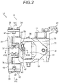
Fig. 2] Fig. 2 is a side view of the disc brake apparatus shown inFig. I . - [
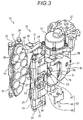
Fig. 3] Fig. 3 is an exploded perspective view of the disc brake apparatus shown inFig. 1 with a spring member removed therefrom. - [
Fig. 4] Fig. 4 is an exploded perspective view of a base member and a link arm shown inFig. 3 . - [
Fig. 5] Fig. 5A is an enlarged view of the link arm and a pressure plate shown inFig. 4 , andFig. 5B is a sectional view of the link arm. - [
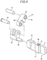
Fig. 6] Fig. 6 is an exploded perspective view of the link arm shown inFig. 5A . - [
Fig. 7] Fig. 7 is a sectional view taken along a line indicated by and viewed from arrows VII-VII inFig. 2 . - [
Fig. 8] Fig. 8 is a sectional view taken along a line indicated by and viewed from arrows VIII-VIII inFig. 2 . - [
Fig. 9] Fig. 9 shows schematic views of a main part of the disc brake apparatus illustrating an operation example of the link arm, whereinFigs. 9A and 9B are a side view and a front view, respectively, of a pad which is new andFigs. 9C and 9D are a side view and a front view, respectively, of the pad which is worn. - [
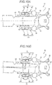
Fig. 10] Fig. 10A is a plan view of the disc brake apparatus shown inFig. 1 when the brake is applied in a normal state, andFig. 10B is a plan view of the disc brake apparatus shown inFig. 1 when the brake is applied with a wheel inclined. - (
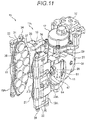
Fig. 11] Fig. 11 is a perspective view of a disc brake apparatus according to a second embodiment of the invention. - [
Fig. 12] Fig. 12 is a sectional view taken along a line indicated by and viewed from arrows XII-XII inFig. 11 . - [
Fig. 13] Fig. 13 is a side view of a conventional disc brake apparatus. - Hereinafter, embodiments of the present invention will be described with reference to the drawings.
- As shown in
Figs. 1 to 3 , adisc brake apparatus 11 according to a first embodiment of the invention will be described as being applied to adisc brake 13 for a railway vehicle. The disc brake apparatus according to the invention can also be applied to an industrial brake apparatus which generates a braking force against a rotary member as in an elevator, for example, in addition to thedisc brake 13 for a railway vehicle. - The
disc brake apparatus 11 according to the first embodiment includes a caliper body (a base member) 25, a pair ofbrake arms 15 which are supported so as to be swingable relative to thecaliper body 25, anactuator 17 which is connected to swing ends 33 of the pair ofbrake arms 15 so as to move thebrake arms 15 away from each other, pad holdingmembers 19 which are supported at the other swing ends 35 of the pair ofbrake arms 15 so as to turn freely thereat, pad assemblies (pads) 21 which are held on thepad holding members 19, and a parallelism maintaining control mechanism 23 (refer toFig. 3 ). - The
caliper body 25, which is the base member, is fixed to a bogie or the like of a vehicle by asupport 27. The pair ofbrake arms 15 are supported so as to be swingable relative to thecaliper body 25 by arm shafts 29 (for example, swing shafts whose axes extend along an up-and-down direction). Theactuator 17 is accommodated in thecaliper body 25. - The
actuator 17 includes a motor gear unit which is made up of an electric motor and a speed reduction mechanism, a hydraulic driving mechanism or an pneumatic driving mechanism, a servo mechanism and a pair ofrods 31. In theactuator 17, therods 31 are reciprocated via the servo mechanism as a result of the motor gear unit or the like being driven. The pair ofrods 31 are connected to one of the swing ends 33 of the pair ofbrake arms 15. When activated, theactuator 17 causes one of the swing ends 33 of the pair ofbrake arms 15 to move away from each other viareciprocating rods 31. As a result, the other of the swing ends 35 of the pair ofbrake arms 15 are caused to move towards each other so as to narrow a gap therebetween. - The pad holding members 19 (also referred to as pad holders) are supported individually at the other swing ends 35 of the pair of
brake arms 15 so as to turn (tilt) freely thereat by holder shafts 37 (for example, turning shafts whose axes extend along the up-and-down direction). - Dovetail grooves 20 (refer to
Fig. 8 ) are carved individually on facing surfaces of the pair ofpad holding members 19 which constitute inner surfaces thereof in a direction which follows theholder shafts 37. Thepad assemblies 21 are individually slid to be inserted into thedovetail grooves 20 from lower sides thereof as shown inFig. I . - A plurality of
pads 39 are held on each of thepad assemblies 21 in such a way that lining surfaces 4 thereof are directed so as to face a disc rotor (or a side surface of awheel 43 shown inFig. 7 ). Thepad assembly 21 which is mounted in thedovetail groove 20 on thepad holding member 19 is fixed to thepad holding member 19 by fastening anchor blocks 22 which are attached individually to an upper end and lower end of thepad assembly 21 to thepad holding member 19 with bolts 24 (refer toFig. 1 ). - In this embodiment, the lining surfaces 41 of the
pads 39 will be described as being pressed against both side surfaces of the disc rotor which is assembled to thewheel 43 to execute a braking operation (refer toFig. 7 ). Of course, thedisc brake apparatus 11 may configured so that a disc rotor (whose illustration is omitted) provided separately from thewheel 43 is press held by the lining surfaces 41 of thepads 39 to brake thewheel 43. - As shown in
Fig. 3 , the parallelism maintainingcontrol mechanism 23 according to the first embodiment is configured to press the lining surfaces 41 of thepads 39 which are held on thepad holding member 19 against a side surface of the wheel 43 (the disc rotor) in parallel and has apressure plate 49, alink arm 47 and aspring member 45. - As shown in
Fig. 4 , thecaliper body 25 has a pair of bearingbosses 51 which are formed cylindrical to support thecorresponding arm shafts 29. Fixingholes 53 are opened individually in the bearingbosses 51 so as to be parallel to the side surfaces of the wheel 43 (the disc rotor). Thepressure plate 49 is supported in the fixinghole 53 of the bearingboss 51 so as to be brought into abutment with thepad holding member 19 via thelink arm 47. - As shown in
Figs. 5 and6 , thepressure plate 49 is brought into abutment with a back side (an opposite side to a side which faces the disc rotor) of thepad holding member 19. Thepressure plate 49 is formed substantially into a short strip-like shape which is elongated horizontally and is disposed in a direction which follows a center axis of the fixinghole 53. Athick portion 55 is formed at one end portion or a proximal end portion of thepressure plate 49. A moving shaft inserting hole 56 (refer toFig. 8 ) is formed in thisthick portion 55, and a movingshaft 57, which will be described later, of thelink arm 47 is inserted into this movingshaft inserting hole 56. A pair of engagingholes 59, whose center axes extend in the up-and-down direction, are depressed on substantially central portions of an upper and lower surfaces of thepressure plate 49 which are at right angles to anabutment surface 71 thereof. The engagingholes 59 of thepressure plate 49 are locked individually by distal ends (locking projecting portions) of theholder shafts 37. The distal ends of theholder shafts 37 are loosely fitted in the engagingholes 59 of thepressure plate 49 so as to provide a gap which permits a predetermined inclination of thepressure plate 49 when the wheel 43 (the disc rotor) is inclined. This allows thepressure plate 49 and theholder shafts 37 to move relatively in a radial direction of theholder shafts 37, whereby there is no such situation that a relative movement of thepressure plate 49 to thepad member 19 is interrupted. - A
guide portion 72 is provided on theabutment surface 71 of thepressure plate 49 so as to protrude therefrom, so that theguide portion 72 is brought into engagement with aguide groove 26 which is formed on a back surface of thepad holding member 19 so as to extend in the up-and-down direction (refer toFig. 8 ). Then, theabutment surface 71 of thepressure plate 49 is guided so as to move relative to thepad holding member 19. - As shown in
Figs. 5 and6 , thelink arm 47, which supports thepressure plate 49 on the bearingboss 51 of thecaliper body 25, is made up of a fixingshaft 61, the movingshaft 57, a firstjoint member 65 and a secondjoint member 67 which make up at least two of joint members, and a connectingshaft 63. The fixingshaft 61 is fixed in fixinghole 53 of the bearingboss 51 to thereby be provided so as to project from thecaliper body 25 in parallel to the side surface of the wheel 43 (the disc rotor). Then, thepressure plate 49 is pressed against a longitudinally middle portion of thepad holding member 19 along theholder shafts 37. - The moving
shaft 57 is provided parallel to the fixingshaft 61 and supports thepressure plate 49 so as not only to rotate but also to move back and forth freely thereon. The movingshaft 57 is fitted in the moving shaft inserting hole 56 (refer toFig. 8 ) which is opened in thethick portion 55 of thepressure plate 49 via a slidingbush 58 so as not only to rotate but also to move back and forth freely. The movingshaft 57 which supports thepressure plate 49 and the fixingshaft 61 which is fixed in the bearingboss 51 of thecaliper body 25 are connected together by means of the firstjoint member 65 and the secondjoint member 67 which make up the plurality of joint members. - The joint members of the invention are made up of at least two of joint members which connect the fixing
shaft 61 and the movingshaft 57 together. In the first embodiment, the joint members are made up of the firstjoint member 65 which is a fixing shaft side joint member and the secondjoint member 67 which is a moving shaft side joint member. The fixingshaft 61 is supported rotatably at one end portion and the connectingshaft 63 is supported rotatably at the other end portion of the firstjoint member 65. The connectingshaft 63 is fixed to one end portion and the movingshaft 57 is fixed to the other end portion of the secondjoint member 67. - The connecting shaft of the invention is made up of at least one of shafts which support rotatably the joint members. In this embodiment, since the joint members are made up of the first
joint member 65 and the secondjoint member 67, there is provided one connecting shaft, which is the connectingshaft 63, for connecting these joint members together. Slidingbushes 69 are interposed individually in a portion where the fixingshaft 61 penetrates the firstjoint member 65 and a portion where the connectingshaft 63 penetrates the firstjoint member 65. - The fixing
shaft 61, the connectingshaft 63 and the movingshaft 57 of thelink arm 47 are all disposed parallel to the side surface of the wheel 43 (the disc rotor) and directed in the same direction (a direction which is at right angles to the up-and-down direction). In thelink arm 47 which is configured in the way described above, the movingshaft 57 can move in a direction in which the movingshaft 57 moves towards or away from the side surface of the wheel 43 (the disc rotor) and in the up-and-down direction (the direction which follows the axes of the holder shafts 37) while being kept parallel to the side surface at all times. - The
spring member 45 elastically biases theabutment surface 71 of thepressure plate 49 in a direction in which theabutment surface 71 is pressed against thepad holding member 19. As described above, the engagingholes 59 of thepressure plate 49 and the distal ends of theholder shafts 37 are brought into engagement with each other with the slight gap provided therebetween. Due to this, thepressure plate 49 can move relative to the distal ends of theholder shafts 37 in the radial direction of theholder shafts 37. Thespring member 45 presses thepressure plate 49 against thepad holding member 19 within the range of this relative movement. As a result, theabutment surface 71 of thepressure plate 49 is pressed against thepad holding member 19 by means of an elastic biasing force of thespring member 45. - The
spring member 45 of the first embodiment is formed of a plate spring which covers anouter surface 73 of thepressure plate 49. Abutment bentportions 74, 75 (refer toFig. 3 ) are formed at both ends of thespring member 45 along the direction of an axis of the movingshaft 57 so as to be bent towards thepressure plate 49. The abutment bentportions spring member 45 are brought into abutment with theouter surface 73 at ends of the pressure plate 49 (refer toFig. 8 ). A pair of upper and lower support plate portions 77 (refer toFig. 7 ) are formed at substantially central portions of an upper and lower edges of thespring member 45 which is formed of the plate spring so as to project from the upper and lower edges towards thepad holding member 19. Thespring member 45 is supported on thepad holding member 19 via theholder shafts 37 as a result of the distal ends (the locking projecting portions) of theholder shafts 37 penetrating throughholes 77a of thesupport plate portions 77. Thespring member 45 covers thepressure plate 49, whereby thespring member 45 also functions to protect thepressure plate 49 from damage made by a piece of flying stone. - In this way, the parallelism maintaining
control mechanism 23 of the first embodiment is made up of the three parts of thelink arm 47, thepressure plate 49 and thespring member 45. Then, thelink arm 47 is made up of the firstjoint member 65 and the secondjoint member 67, the connectingshaft 63, the movingshaft 57 and the slidingbushes 69. These constituent members can be assembled together in advance, and the number of parts to be replaced is reduced, whereby the attachment and replacement are facilitated. - In addition, the
link arm 47 of the parallelism maintainingcontrol mechanism 23 of the first embodiment is disposed near a substantial center along thearm shaft 29 which is the turning center shaft of thebrake arm 15 to connect together thecaliper body 25 and thepad holding member 19. Thus, when compared with a case where the parallelism maintainingcontrol mechanism 23 is disposed at a lower portion, it becomes more difficult for the parallelism maintainingcontrol mechanism 23 to be damaged by a piece of flying stone or the like. - Then, the parallelism maintaining
control mechanism 23 of the first embodiment can press the lining surfaces 41 of thepads 39 which are held by thepad holding member 19 against the side surface of the wheel 43 (the disc rotor) in parallel not only when new pads are used as shown inFigs. 9A, 9B but also when the pads get worn as shown inFigs. 9C, 9D . - Next, the operation or the
disc brake apparatus 11 which is configured in the way described heretofore will be described. - In the
disc brake apparatus 11 according to the first embodiment, the pair ofbrake arms 15 are supported on thecaliper body 25 so as to be swingable about thearm shafts 29. In the pair ofbrake arms 15, when the swing ends 33 are caused to move away from each other by theactuator 17 provided on thecaliper body 25, the space defined by the other swing ends 35 thereof is narrowed. Thepad holding members 19 which hold thepads 39 are supported at the other swing ends 35 of the pair ofbrake arms 15 so as to turn about theholder shafts 37. As shown inFig. 10A , thepad holding members 19 which are supported at the other swing ends 35 of thebrake arms 15 so as to turn freely by the turningshafts 37 arc guided by the corresponding parallelism maintainingcontrol mechanisms 23 so that the lining surfaces 41 of thepads 39 which are held by thepad holding members 19 become parallel to the wheel 43 (the disc rotor). - The parallelism maintaining
control mechanisms 23 each have thepressure plate 49 and thelink arm 47 which bring thepads 39 into press contact with the wheel 43 (the disc rotor) in a parallel fashion. Thelink arms 47 are each made up of the fixingshaft 61, the movingshaft 57, the firstjoint member 65 and the secondjoint member 67, and the connectingshaft 63. The fixingshaft 61 projects from the bearingboss 51 of thecaliper body 25 so as to be parallel to the side surface of the wheel 43 (the disc rotor). The movingshaft 57, which is directed in the same direction as the fixingshaft 61, is supported movably on the fixingshaft 61 via the firstjoint member 65 and the secondjoint member 67 which are connected together by the connectingshaft 63, which is directed in the same direction as the fixingshaft 61. Then, the movingshaft 57 is supported on the bearingboss 51 of thecaliper body 25 by thelink arm 47 so as to move not only in the up-and-down direction but also in the direction in which the movingshaft 57 moves towards or away from the wheel 43 (the disc rotor) while being kept parallel to the side surface of the wheel 43 (the disc rotor). - The
spring member 45 is fixed to thepad holding member 19, and thespring member 45 elastically biases theabutment surface 71 of thepressure plate 49 in the direction in which theabutment surface 71 is pressed against the back surface of thepad holding member 19. Namely, thepressure plate 49 is brought into abutment with the back surface of thepad holding member 19 by means of the biasing force of thespring member 45. Thespring member 45 presses theouter surface 73 of thepressure plate 49 at both the ends of thepressure plate 49 with theholder shafts 37 held therebetween. Thespring member 45 presses thepressure plate 49 against thepad holding member 19 so as not to generate a moment about theholder shafts 37 in thepressure plate 49. By adopting this configuration, in a normal state where a load of a certain magnitude or greater is not applied to the parallelism maintainingcontrol mechanism 23, the posture of thepad holding member 19 which is tightly secured to theabutment surface 71 of thepressure plate 49 is maintained so that the lining surfaces 41 of thepads 39 become parallel to the wheel 43 (the disc rotor). - The
link arm 47 of the first embodiment has the two joint members or the firstjoint member 65 and the secondjoint member 67. By adopting this configuration, when compared with the conventional suspension link 507 (refer toFig. 13 ) which is one long joint member, the individual joint members can be made short in length, whereby even with the compact construction, thelink arm 47 allows the movingshaft 57 to translate in a horizontal direction relative to the fixingshaft 61. Namely, with theconventional suspension link 507, in order to cause thebrake pad holder 505 to translate as horizontally as possible, the space between the rotating shaft of theattachment bracket 503 and the rotating shaft of thebrake pad holder 505 has to be widened to ensure the great turning radius. - Consequently, it is possible to provide the
disc brake apparatus 11 which includes the compact parallelism maintainingcontrol mechanisms 23. - On the other hand, in the
disc brake apparatus 11 of the first embodiment, when a load of a certain degree or greater is applied to the pad holding memberl9 via thepads 39 due to a reaction force from the wheel 43 (the disc rotor) or the like whereby a moment load of thepad holding member 19 is transmitted to theabutment surface 71 of thepressure plate 49, thepressure plate 49 is allowed to move relative to thepad holding member 19 against the biasing force of thespring member 45. Namely, theholder shafts 37 and thepressure plate 49 move relative to each other by deforming elastically thespring member 45 within the range of the slight gap. - The
abutment surface 71 of thepressure plate 49 and thepad holding member 19 are released from the tightly secured state, thereby making it possible to generate a gap therebetween. Namely, as shown inFig. 10B , in the event that a great moment load is generated in thelink arm 47 when the wheel 43 (the disc rotor) is inclined, thespring member 45 deflects (is elastically deformed), and thepad holding member 19 and thelink arm 47 are separated from each other. The parallelism maintainingcontrol mechanism 23 is required to deal with an inclination of the wheel 43 (the disc rotor) of a maximum angle of ± 3°. Consequently, the pad holding member 19 (the pads 39) can change its angle along the wheel 43 (the disc rotor), whereby the lining surfaces 41 of thepads 39 can be pressed against the wheel 43 (the disc rotor) uniformly. As a result, with thedisc brake apparatus 11, eccentric wear or drag is restrained from being generated in thepads 39. - In addition, since the
abutment surface 71 of thepressure plate 49 can move relative to thepad holding member 19, an excessive load that would otherwise be applied to thelink arm 47 is eliminated. Namely, although thepads 39 maintain parallel postures along the axis of the movingshaft 57 when thepad holding member 19 is opened moderately, when the brake is applied, thepads 39 can change their postures along the wheel 43 (the disc rotor). - With the
disc brake apparatus 11 of the first embodiment, the distal ends (the locking projecting portions) of theholder shafts 37 which support thepad holding member 19 so as to turn freely are locked in the engagement holes 59 which are depressed on the upper and lower surfaces of thepressure plate 49, whereby thepressure plate 49 can be assembled to thepad holding member 19, this facilitating the assemblage of thepressure plate 49 to thepad holding member 19. Since the distal ends (the locking projecting portions) of theholder shafts 37 are individually loosely fitted in the engagement holes 59 of thepressure plate 49 so as to generate the gap which permits the predetermined inclination of the locking projecting portion when the wheel 43 (the disc rotor) is inclined, there is no such situation that the relative movement of thepressure plate 49 to thepad holding member 19 is interrupted. - With the
disc brake apparatus 11 of the first embodiment, since theabutment surface 71 of thepressure plate 49 is guided so as to move relative to thepad holding member 19, theabutment surface 71 of thepressure plate 49 can be caused to move smoothly relative to thepad holding member 19. - In addition, with the
disc brake apparatus 11 of the first embodiment, the fixingshaft 61 is fixed to each of the bearingbosses 51 which support the pair ofbrake arms 15 so as to be swingable relative to thecaliper body 25, and thepressure plate 49 is pressed against the longitudinally middle portion of thepad holding member 19 along the turning shafts thereof. Then, the parallelism maintainingcontrol mechanism 23 is situated so as to connect the longitudinally middle portion of thepad holding member 19 along the turning shafts thereof which lie near the center of thepad assembly 21 and the bearingboss 51 of thecaliper body 25 together and is configured light in weight and small in size. - With the
disc brake apparatus 11 of the first embodiment, thepressure plate 49 is covered by thespring member 45 to thereby be protected against damage made by a piece of flying stone. In addition, since thespring member 45 is disposed on a mechanism surface side (an opposite side to a side facing the wheel 43) of the parallelism maintainingcontrol mechanism 23 which is visible from an exterior portion, it is possible to easily verify how thespring member 45 is attached to the parallelism maintainingcontrol mechanism 23 or whether or not thespring member 45 is damaged in a visual fashion. Additionally, the throughholes 77a are formed in thesupport plate portions 77 which are formed at the upper and lower edges of thespring member 45 which is formed of the plate spring, and the distal ends (the locking projecting portions) of theholder shafts 37 which lock the engagement holes 59 of thepressure plate 49 are put through the throughholes 77a, whereby thespring member 45 is supported on thepad holding member 19. - In addition, with the
disc brake 13 for a railway vehicle which includes thedisc brake apparatus 11 configured as described above, when the wheel 43 (the disc rotor) is inclined, the lining surfaces 41 of thepads 39 are allowed to follow the wheel 43 (the disc rotor) in parallel. By doing so, when braking the railway vehicle which is running on a curved track or a track having alternate right and left turns, in the event that the wheel 43 (the disc rotor) is inclined, thepad holding member 19 which is released from the tightly secured state with thepressure plate 49 against the biasing force of thespring member 45 follows the wheel 43 (the disc rotor) in parallel. As a result, a load is eliminated which would otherwise be applied to the parallelism maintainingcontrol mechanism 23 by the inclined wheel 43 (disc rotor). - In this way, in the
disc brake 13 for a railway vehicle, in the event that the pads 39 (the pad assembly 21) are inclined when braking the railway vehicle which is running on the curved track or the track having alternate left and right turns, the tightly secured state between thepads 39 and thepressure plate 49 is released so as not to interrupt the braking operation of thepads 39. Moreover, thelink arm 47 of the parallelism maintainingcontrol mechanism 23 is also prevented from bearing an excessive load. - Consequently, according to the
disc brake apparatus 11 of the first embodiment, the postures of thepads 39 are kept parallel to the wheel 43 (the disc rotor) by the compact parallelism maintainingcontrol mechanism 23, and at the same time, the eccentric wear and drag can be prevented from being generated in thepads 39 by the parallelism maintainingcontrol mechanism 23. - According to the
disc brake 13 for a railway vehicle of the first embodiment, thepads 39 are allowed to follow the inclined wheel 43 (disc rotor), whereby the eccentric wear and drag can be prevented from being generated in thepads 39. - Next, a
disc brake apparatus 11A according to a second embodiment of the invention will be described. - As shown in
Figs. 11 and12 , adisc brake apparatus 11A according to a second embodiment is configured the same as thedisc brake apparatus 11 according to the first embodiment except that the parallelism maintainingcontrol mechanism 23 is replaced by a parallelism maintainingcontrol mechanism 23A. Thus, like reference numerals will be given to like members to those of thedisc brake apparatus 11 of the first embodiment, and a detailed description of the like members will be omitted here. - The parallelism maintaining
control mechanism 23A according to the second embodiment is configured to press lining surfaces 41 ofpads 39 which are held on apad holding member 19A against a side surface of a wheel 43 (a disc rotor) in parallel and has a movingshaft inserting hole 93 which is formed in thepad holding member 19A and alink arm 47, as shown inFigs. 11 and12 . - A moving
shaft 57 of thelink arm 47 according to the second embodiment is disposed parallel to a fixingshaft 61 and is fitted in the movingshaft inserting hole 93 of thepad holding member 19A via a slidingbush 95 so as not only to rotate but also to move back and forth, as shown inFig. 12 . - Next, the operation of the
disc brake apparatus 11A which is configured in the way described heretofore will be described. - With the
disc brake apparatus 11A according to the second embodiment, thepad holding member 19A is guided by the parallelism maintainingcontrol mechanism 23A so that the lining surfaces 41 of thepads 39 held on thepad holding member 19A become parallel to the wheel 43 (the disc rotor). - The parallelism maintaining
control mechanisms 23A each have thelink arm 47 which bring thepads 39 into press contact with the wheel 43 (the disc rotor) in a parallel fashion. Thelink arms 47 are each made up of the fixingshaft 61, the movingshaft 57, the firstjoint member 65 and the secondjoint member 67, and the connectingshaft 63. The movingshaft 57 is supported on a bearingboss 51 of acaliper body 25 by thelink arm 47 so as to move not only in an up-and-down direction but also in a direction in which the movingshaft 57 moves towards or away from the wheel 43 (the disc rotor) while being kept parallel to the side surface of the wheel 43 (the disc rotor). - The moving
shaft inserting hole 93 in thepad holding member 19A is fitted on the movingshaft 57 in a direction in which the lining surfaces 41 of thepads 39 become parallel to the wheel 43 (the disc rotor) in such a way that the movingshaft inserting hole 93 rotates and moves back and forth on the movingshaft 57. - By adopting this configuration, the parallelism maintaining
control mechanism 23A maintains the posture of thepad holding member 19A so that the lining surfaces 41 of thepads 39 become parallel to the wheel 43 (the disc rotor). - Consequently, it is possible to provide the
disc brake apparatus 11A which includes the compact parallelism maintainingcontrol mechanisms 23A. - Further, according to the
disc brake apparatuses control mechanism arm shaft 29 which constitutes the swing axis of thebrake arm 15 so as to connect thecaliper body 25 and thepad holding member 19 together and no braking torque is inputted directly into the parallelism maintainingcontrol mechanism - Here, aspects of the disc brake apparatus and the disc brake for a railway vehicle according to the embodiments of the invention will briefly be summarized item by item below.
- [1] The disc brake apparatus (11A) including:
- the base member (the caliper body 25);
- the pair of brake arms (15) which are pivotally supported to be swingable with respect to the base member (the caliper body 25);
- the actuator (17) which is connected to the swing ends (33) of the pair of brake arms (15) so as to move the brake arms (15) away from each other;
- the pad holding members (19) which are supported pivotally at the other swing ends (35) of the pair of brake arms (15) so as to turn freely thereat; and
- the parallelism maintaining control mechanisms (23A) which bring the lining surfaces (41) of the pads (39) which are held on the pad holding members (19) into press contact with the disc rotor (the wheel 43) in a parallel fashion.
The parallelism maintaining control mechanisms (23A) are each disposed near the center along the swing axis (the arm shaft 29) of the brake arm (15) so as to connect the base member (the caliper body 25) and the pad holding member (19) together.
- [2] The disc brake apparatus (11A) including:
- the base member (the caliper body 25);
- the pair of brake arms (15) which are pivotally supported to be swingable with respect to the base member (the caliper body 25);
- the actuator (17) which is connected to the swing ends (33) of the pair of brake arms (15) so as to move the brake arms (15) away from each other;
- the pad holding members (19) which are supported pivotally at the other swing ends (35) of the pair of brake arms (15) so as to turn freely thereat; and
- the parallelism maintaining control mechanisms (23A) which bring the lining surfaces (41) of the pads (39) which are held on the pad holding members (19) into press contact with the disc rotor (the wheel 43) in a parallel fashion.
The parallelism maintaining control mechanisms (23A) each include the link arm (47) which includes:- the fixing shaft (61) which projects from the base member (the caliper body 25) so as to be parallel to the side surface of the disc rotor (the wheel 43);
- the moving shaft (57) which is disposed parallel to the fixing shaft (61) and which is fitted in the moving shaft insertion hole (93) in the pad holding member (19A) so as not only to rotate but also to move back and forth therein;
- at least two of joint members (the first
joint member 65 and the second joint member 67) which connect the fixing shaft (61) and the moving shaft (57) together in parallel; and - at least one of connecting shafts (63) which support the joint members so at to rotate thereon.
- [3] The disc brake apparatus (11) including:
- the base member (the caliper body 25);
- the pair of brake arms (15) which are pivotally supported to be swingable with respect to the base member (the caliper body 25);
- the actuator (17) which is connected to the swing ends (33) of the pair of brake arms (15) so as to move the brake arms (15) away from each other;
- the pad holding members (19) which are supported pivotally at the other swing ends (35) of the pair of brake arms (15) so as to turn freely thereat; and
- the parallelism maintaining control mechanisms (23) which bring the lining surfaces (41) of the pads (39) which are held on the pad holding members (19) into press contact with the disc rotor (the wheel 43) in a parallel fashion.
The parallelism maintaining control mechanisms (23) each includes:- the pressure plate (49) which is brought into abutment with the pad holding member (19);
- the link arm (47) including:
- the fixing shaft (61) which projects from the base member (the caliper body 25) so as to be parallel to the side surface of the disc rotor (the wheel 43);
- the moving shaft (57) which is disposed parallel to the fixing shaft (61) and which supports the pressure plate (49) so as not only to rotate but also to move back and forth freely thereon;
- at least two of joint members (the first
joint member 65 and the second joint member 67) which connect the fixing shaft (61) and the moving shaft (57) together in parallel; and - at least one of connecting shafts (63) which support the joint members so at to rotate thereon; and
- the spring member (45) which elastically biases the abutment surface (71) of the pressure plate (49) in the direction in which the abutment surface (71) is pressed against the pad holding member (19).
- [4] The disc brake apparatus (11) according to [3] above, wherein the pair of engagement holes (59) whose center axes extend along the up-and-down direction are depressed into the upper and lower surfaces of the pressure plate (49) which are at right angles to the abutment surface (71) thereof, and wherein the locking projecting portions (the distal ends of the holder shafts 37) which lock individually the engagement holes (59) to the pad holding member (19) are fitted individually loosely in the holes so as to generate the gap which permits the predetermined inclination of the locking projecting portions.
- [5] The disc brake apparatus (11) according to [3] or [4] above, wherein the abutment surface (71) of the pressure plate (49) is guided so as to move relative to the pad holding member (19).
- [6] The disc brake apparatus(11) according to any one of [3] to [5] above, wherein the fixing shaft (61) is fixed to each of the bearing bosses (51) which support the pair of brake arms (15) so as to be swingable relative to the base member (the caliper body 25), and wherein the pressure plate (49) is pressed against the longitudinally middle portion of the pad holding member (19) along the turning shaft thereof.
- [7] The disc brake apparatus (11) according to any one of [3] to [6] above, wherein the spring member (45) is formed of the plate spring which covers the outer surface (73) of the pressure plate (49).
- [8] The disc brake (13) for a railway vehicle including the disc brake apparatus (11, 11A) according to any one of [1] to [7].
- The invention is not limited to the embodiments that have been described heretofore and hence can be modified or improved as required. In addition, the materials, shapes, dimensions, numbers, arranging positions and the like of the constituent elements described in the embodiments are arbitrary and hence are not limited thereto, provided that those elements can achieve the invention.
- This patent application is based on
Japanese Patent Application (No. 2014-169559) filed on August 22, 2014 - According to the disc brake apparatus and the disc brake for a railway vehicle which have been described heretofore, the postures of the pads arc kept parallel to the disc rotor by the compact parallelism maintaining control mechanism, whereby eccentric wear and drag can be prevented from being generated in the pads.
-
- 11: disc brake apparatus; 13: disc brake for railway vehicle; 15: brake arm; 17: actuator; 19: pad holding member; 23: parallelism maintaining control mechanism; 25 caliper body (base member); 33: one swing end; 35: the other swing end; 39: pad; 41: lining surface; 43: wheel (disc rotor); 45: spring member; 47: link arm; 49: pressure plate; 57: moving shaft; 61: fixing shaft; 63: connecting shaft; 65: first joint member (joint member); 67: second joint member (joint member); 71: abutment surface; 73: outer surface.
Claims (8)
- A disc brake apparatus comprising:a base member;a pair of brake arms pivotally supported to be swingable with respect to the base member;an actuator connected to one of swing ends of each of the pair of brake arms so as to move the brake arms away from each other;a pad holding member pivotally supported at the other of the swing ends of the each of the pair of brake arms so as to freely turn; anda parallelism maintaining control mechanism configured to press a lining surface of a pad held on the pad holding member to a disc rotor in a parallel fashion,wherein the parallelism maintaining control mechanism is disposed near a center along a swing axis of the each of the brake arms so as to connect the base member and the pad holding member together.
- A disc brake apparatus comprising:a base member;a pair of brake arms pivotally supported to be swingable with respect to the base member;an actuator connected to one of swing ends of each of the pair of brake arms so as to move the brake arms away from each other;a pad holding member pivotally supported at the other of the swing ends of the each of the pair of brake arms so as to freely turn; anda parallelism maintaining control mechanism configured to press a lining surface of a pad held on the pad holding member to a disc rotor in a parallel fashion,wherein the parallelism maintaining control mechanism includes a link arm which comprises:a fixing shaft projecting from the base member so as to be parallel to a side surface of the disc rotor;a moving shaft disposed parallel to the fixing shaft and fitted in a moving shaft insertion hole in the pad holding member to be rotatable and movable back and forth;at least two joint members which connect the fixing shaft and the moving shaft together in parallel; andat least one connecting shaft which supports the joint members so at to be rotatable with respect to each other.
- A disc brake apparatus comprising:a base member;a pair of brake arms pivotally supported to be swingable with respect to the base member;an actuator connected to one of swing ends of each of the pair of brake arms so as to move the brake arms away from each other;a pad holding member pivotally supported at the other of the swing ends of the each of the pair of brake arms so as to freely turn; anda parallelism maintaining control mechanism configured to press a lining surface of a pad held on the pad holding member to a disc rotor in a parallel fashion,wherein the parallelism maintaining control mechanism includes:a pressure plate which is brought into abutment with the pad holding member;a link arm including:a fixing shaft projecting from the base member so as to be parallel to a side surface of the disc rotor;a moving shaft which is disposed parallel to the fixing shaft and which supports the pressure plate so as to be rotatable and movable back and forth;at least two joint members which connect the fixing shaft and the moving shaft together in parallel; andat least one connecting shaft which supports the joint members so at to be rotatable with respect to each other; anda spring member which elastically biases an abutment surface of the pressure plate in a direction in which the abutment surface is pressed against the pad holding member.
- The disc brake apparatus according to Claim 3, wherein a pair of engagement holes whose center axes extend along an up-and-down direction are depressed on upper and lower surfaces of the pressure plate which are perpendicular to the abutment surface, and
wherein locking projecting portions which respectively lock the engagement holes to the pad holding member are respectively fitted loosely in the engagement holes with gaps for permitting the locking projecting portions from inclining in predetermined inclinations. - The disc brake apparatus according to Claim 3 or 4, wherein the abutment surface of the pressure plate is guided so as to move relative to the pad holding member.
- The disc brake apparatus according to any one of Claims 3 to 5, wherein the fixing shaft is fixed to each of bearing bosses which pivotally support the pair of brake arms so as to be swingable relative to the base member, and
wherein the pressure plate is pressed against a longitudinally middle portion of the pad holding member along a turning shaft of the pressure plate. - The disc brake apparatus according to any one of Claims 3 to 6, wherein the spring member is formed of a plate spring which covers an outer surface of the pressure plate.
- A disc brake for a railway vehicle comprising the disc brake apparatus according to any one of Claims 1 to 7.
Applications Claiming Priority (2)
| Application Number | Priority Date | Filing Date | Title |
|---|---|---|---|
| JP2014169559A JP6396721B2 (en) | 2014-08-22 | 2014-08-22 | Disc brake device and disc brake for railway |
| PCT/JP2015/073393 WO2016027860A1 (en) | 2014-08-22 | 2015-08-20 | Disc brake device and disc brake for railway |
Publications (3)
| Publication Number | Publication Date |
|---|---|
| EP3193036A1 true EP3193036A1 (en) | 2017-07-19 |
| EP3193036A4 EP3193036A4 (en) | 2018-04-25 |
| EP3193036B1 EP3193036B1 (en) | 2023-03-15 |
Family
ID=55350801
Family Applications (1)
| Application Number | Title | Priority Date | Filing Date |
|---|---|---|---|
| EP15833883.0A Active EP3193036B1 (en) | 2014-08-22 | 2015-08-20 | Disc brake device and disc brake for railway |
Country Status (5)
| Country | Link |
|---|---|
| US (1) | US10807619B2 (en) |
| EP (1) | EP3193036B1 (en) |
| JP (1) | JP6396721B2 (en) |
| CN (1) | CN106662182B (en) |
| WO (1) | WO2016027860A1 (en) |
Families Citing this family (7)
| Publication number | Priority date | Publication date | Assignee | Title |
|---|---|---|---|---|
| EP3336374B1 (en) | 2016-12-16 | 2022-06-22 | Ratier-Figeac SAS | Mechanical brake |
| EP3540258B1 (en) * | 2018-03-12 | 2023-04-26 | KNORR-BREMSE Systeme für Schienenfahrzeuge GmbH | Pull rod device arrangement of a brake caliper and brake caliper |
| DE102018118517A1 (en) * | 2018-07-31 | 2020-02-06 | Knorr-Bremse Systeme für Schienenfahrzeuge GmbH | Pad holder for a brake pad holder of a rail vehicle and brake pad holder |
| CN111059176B (en) * | 2019-11-19 | 2021-06-04 | 中车株洲电力机车有限公司 | Brake lining support device with deflection prevention function |
| CN115720611B (en) * | 2020-04-24 | 2025-09-16 | 伏尔甘度巴西有限公司 | Electric hydraulic disc brake |
| DE102022106026B4 (en) | 2022-03-15 | 2025-10-02 | Knorr-Bremse Systeme für Schienenfahrzeuge GmbH | Brake pad for a disc brake of a rail vehicle and disc brake |
| EP4310358A1 (en) * | 2022-07-19 | 2024-01-24 | KNORR-BREMSE Systeme für Nutzfahrzeuge GmbH | Brake assembly for braking at least one wheel of a vehicle |
Family Cites Families (25)
| Publication number | Priority date | Publication date | Assignee | Title |
|---|---|---|---|---|
| US2890767A (en) * | 1955-04-25 | 1959-06-16 | American Steel Foundries | Rotor brake |
| US4060153A (en) * | 1976-09-14 | 1977-11-29 | Jacob Kobelt | Self-balancing brake shoes for caliper brake |
| SE423515B (en) * | 1980-10-16 | 1982-05-10 | Knorr Bremse Gmbh | SUSPENSION BODY FOR A DISC BRAKE UNIT OF A RAILWAY VEHICLE |
| US4393962A (en) * | 1981-03-05 | 1983-07-19 | Jacob Kobelt | Self-centering device for caliper brake assembly |
| JPS61116128A (en) * | 1984-11-13 | 1986-06-03 | Ishikawajima Harima Heavy Ind Co Ltd | disc brake device |
| US4697671A (en) * | 1985-04-12 | 1987-10-06 | Twiflex Limited | Brakepad assembly for disc brake |
| US5058712A (en) * | 1989-07-07 | 1991-10-22 | American Standard Inc. | Pre-loading pivotal pin connection for a disc brake assembly |
| DE4431353C1 (en) * | 1994-09-02 | 1996-03-28 | Knorr Bremse Systeme | Brake caliper unit for disc brakes of vehicles, in particular rail vehicles |
| DE19945701A1 (en) * | 1999-09-23 | 2001-04-19 | Knorr Bremse Systeme | Brake actuator |
| US6551003B1 (en) * | 2000-09-25 | 2003-04-22 | Acertek S.A. De C.V. | Joint for pivotally joining a brake head to a brake beam |
| DE102004062731A1 (en) | 2004-06-04 | 2005-12-29 | Continental Teves Ag & Co. Ohg | Disc brake with Federanordung |
| CN100480531C (en) * | 2004-06-04 | 2009-04-22 | 大陆-特韦斯贸易合伙股份公司及两合公司 | Spring device for a disc brake |
| SE531450C2 (en) | 2006-04-07 | 2009-04-07 | Faiveley Transport Nordic Ab | disc brake caliper |
| JP4809282B2 (en) * | 2007-04-12 | 2011-11-09 | ナブテスコ株式会社 | Brake cylinder device and brake caliper device |
| JP4946638B2 (en) * | 2007-05-31 | 2012-06-06 | 住友金属工業株式会社 | Disc brake device for railway vehicles |
| GB201009030D0 (en) * | 2010-06-01 | 2010-07-14 | Meritor Heavy Vehicle Braking | Disc brake |
| FR2982923B1 (en) * | 2011-11-21 | 2014-05-02 | Ratier Figeac Soc | ROTARY SHAFT BRAKE SYSTEM, ESPECIALLY FOR ROTOR OR AIRCRAFT PROPELLER, COMPRISING A LINEAR ACTUATOR |
| WO2013077273A1 (en) * | 2011-11-25 | 2013-05-30 | ナブテスコ株式会社 | Brake cylinder device and disk brake device |
| JP5880003B2 (en) * | 2011-12-14 | 2016-03-08 | 新日鐵住金株式会社 | Caliper brake device for railway vehicles |
| JP5921997B2 (en) * | 2012-09-18 | 2016-05-24 | ナブテスコ株式会社 | Disc brake pad and brake caliper device |
| JP6001091B2 (en) * | 2012-12-26 | 2016-10-05 | ナブテスコ株式会社 | Disc brake device for railway vehicles |
| JP6092256B2 (en) * | 2012-12-26 | 2017-03-08 | ナブテスコ株式会社 | Disc brake device for railway vehicles |
| CN105308347B (en) * | 2013-06-19 | 2017-02-22 | 新日铁住金株式会社 | Caliper brake device for railway vehicle |
| JP6393521B2 (en) * | 2014-05-27 | 2018-09-19 | Kyb株式会社 | Brake device |
| US11098775B2 (en) * | 2015-08-24 | 2021-08-24 | Nabtesco Corporation | Caliper device and disc brake device including the same |
-
2014
- 2014-08-22 JP JP2014169559A patent/JP6396721B2/en active Active
-
2015
- 2015-08-20 CN CN201580045149.4A patent/CN106662182B/en active Active
- 2015-08-20 US US15/504,819 patent/US10807619B2/en active Active
- 2015-08-20 EP EP15833883.0A patent/EP3193036B1/en active Active
- 2015-08-20 WO PCT/JP2015/073393 patent/WO2016027860A1/en not_active Ceased
Also Published As
| Publication number | Publication date |
|---|---|
| CN106662182B (en) | 2019-03-19 |
| WO2016027860A1 (en) | 2016-02-25 |
| EP3193036B1 (en) | 2023-03-15 |
| US20170267262A1 (en) | 2017-09-21 |
| US10807619B2 (en) | 2020-10-20 |
| EP3193036A4 (en) | 2018-04-25 |
| JP6396721B2 (en) | 2018-09-26 |
| CN106662182A (en) | 2017-05-10 |
| JP2016044751A (en) | 2016-04-04 |
Similar Documents
| Publication | Publication Date | Title |
|---|---|---|
| US10807619B2 (en) | Disc brake device and disc brake for railway | |
| KR101526784B1 (en) | Brake lining for railway vehicles and disc brakes equipped with same | |
| JP4921547B2 (en) | Disc brake caliper | |
| EP3106703A1 (en) | Braking device | |
| EP2787238A1 (en) | Disc-brake device and calipers | |
| KR20160060710A (en) | Brake apparatus | |
| EP2694350B1 (en) | A rail vehicle brake actuator with a brake block holder | |
| CN104884330B (en) | Railway vehicle disc brake apparatus | |
| KR101955136B1 (en) | Brake device and elevator system | |
| JP4921296B2 (en) | Disc brake lever brake sliding link mechanism | |
| JP2002507705A (en) | Disc brake with reduced shear | |
| JP4812688B2 (en) | Floating caliper brake device | |
| JP6480817B2 (en) | Brake device | |
| JP4721984B2 (en) | Caliper brake device for railway vehicles | |
| CN206841646U (en) | bicycle mechanical caliper | |
| CN107244374A (en) | Mechanical calipers for bicycle | |
| JP5361774B2 (en) | Caliper brake device | |
| JP2010007688A (en) | Caliper brake device | |
| JP4566170B2 (en) | Caliper brake device for railway vehicles | |
| JP2017061976A (en) | Disc brakes and disc brakes for railway vehicles | |
| JP4918395B2 (en) | Floating caliper brake device | |
| JP6660216B2 (en) | Brake support member and brake device having the same | |
| JP5167177B2 (en) | Caliper brake device for railway vehicles | |
| JPH04201672A (en) | Disc brake device for rolling stock | |
| JP2021188635A (en) | Brake caliper device |
Legal Events
| Date | Code | Title | Description |
|---|---|---|---|
| STAA | Information on the status of an ep patent application or granted ep patent |
Free format text: STATUS: THE INTERNATIONAL PUBLICATION HAS BEEN MADE |
|
| PUAI | Public reference made under article 153(3) epc to a published international application that has entered the european phase |
Free format text: ORIGINAL CODE: 0009012 |
|
| STAA | Information on the status of an ep patent application or granted ep patent |
Free format text: STATUS: REQUEST FOR EXAMINATION WAS MADE |
|
| 17P | Request for examination filed |
Effective date: 20170221 |
|
| AK | Designated contracting states |
Kind code of ref document: A1 Designated state(s): AL AT BE BG CH CY CZ DE DK EE ES FI FR GB GR HR HU IE IS IT LI LT LU LV MC MK MT NL NO PL PT RO RS SE SI SK SM TR |
|
| AX | Request for extension of the european patent |
Extension state: BA ME |
|
| DAV | Request for validation of the european patent (deleted) | ||
| DAX | Request for extension of the european patent (deleted) | ||
| A4 | Supplementary search report drawn up and despatched |
Effective date: 20180326 |
|
| RIC1 | Information provided on ipc code assigned before grant |
Ipc: F16D 65/02 20060101ALI20180316BHEP Ipc: F16F 1/18 20060101ALI20180316BHEP Ipc: F16D 55/2255 20060101ALI20180316BHEP Ipc: B61H 5/00 20060101ALI20180316BHEP Ipc: F16D 65/095 20060101AFI20180316BHEP |
|
| STAA | Information on the status of an ep patent application or granted ep patent |
Free format text: STATUS: EXAMINATION IS IN PROGRESS |
|
| 17Q | First examination report despatched |
Effective date: 20190805 |
|
| GRAP | Despatch of communication of intention to grant a patent |
Free format text: ORIGINAL CODE: EPIDOSNIGR1 |
|
| STAA | Information on the status of an ep patent application or granted ep patent |
Free format text: STATUS: GRANT OF PATENT IS INTENDED |
|
| INTG | Intention to grant announced |
Effective date: 20221104 |
|
| GRAS | Grant fee paid |
Free format text: ORIGINAL CODE: EPIDOSNIGR3 |
|
| GRAA | (expected) grant |
Free format text: ORIGINAL CODE: 0009210 |
|
| STAA | Information on the status of an ep patent application or granted ep patent |
Free format text: STATUS: THE PATENT HAS BEEN GRANTED |
|
| AK | Designated contracting states |
Kind code of ref document: B1 Designated state(s): AL AT BE BG CH CY CZ DE DK EE ES FI FR GB GR HR HU IE IS IT LI LT LU LV MC MK MT NL NO PL PT RO RS SE SI SK SM TR |
|
| REG | Reference to a national code |
Ref country code: CH Ref legal event code: EP Ref country code: GB Ref legal event code: FG4D |
|
| REG | Reference to a national code |
Ref country code: DE Ref legal event code: R096 Ref document number: 602015082826 Country of ref document: DE |
|
| REG | Reference to a national code |
Ref country code: IE Ref legal event code: FG4D |
|
| REG | Reference to a national code |
Ref country code: AT Ref legal event code: REF Ref document number: 1554172 Country of ref document: AT Kind code of ref document: T Effective date: 20230415 |
|
| P01 | Opt-out of the competence of the unified patent court (upc) registered |
Effective date: 20230512 |
|
| REG | Reference to a national code |
Ref country code: LT Ref legal event code: MG9D |
|
| REG | Reference to a national code |
Ref country code: NL Ref legal event code: MP Effective date: 20230315 |
|
| PG25 | Lapsed in a contracting state [announced via postgrant information from national office to epo] |
Ref country code: RS Free format text: LAPSE BECAUSE OF FAILURE TO SUBMIT A TRANSLATION OF THE DESCRIPTION OR TO PAY THE FEE WITHIN THE PRESCRIBED TIME-LIMIT Effective date: 20230315 Ref country code: NO Free format text: LAPSE BECAUSE OF FAILURE TO SUBMIT A TRANSLATION OF THE DESCRIPTION OR TO PAY THE FEE WITHIN THE PRESCRIBED TIME-LIMIT Effective date: 20230615 Ref country code: LV Free format text: LAPSE BECAUSE OF FAILURE TO SUBMIT A TRANSLATION OF THE DESCRIPTION OR TO PAY THE FEE WITHIN THE PRESCRIBED TIME-LIMIT Effective date: 20230315 Ref country code: LT Free format text: LAPSE BECAUSE OF FAILURE TO SUBMIT A TRANSLATION OF THE DESCRIPTION OR TO PAY THE FEE WITHIN THE PRESCRIBED TIME-LIMIT Effective date: 20230315 Ref country code: HR Free format text: LAPSE BECAUSE OF FAILURE TO SUBMIT A TRANSLATION OF THE DESCRIPTION OR TO PAY THE FEE WITHIN THE PRESCRIBED TIME-LIMIT Effective date: 20230315 |
|
| REG | Reference to a national code |
Ref country code: AT Ref legal event code: MK05 Ref document number: 1554172 Country of ref document: AT Kind code of ref document: T Effective date: 20230315 |
|
| PG25 | Lapsed in a contracting state [announced via postgrant information from national office to epo] |
Ref country code: SE Free format text: LAPSE BECAUSE OF FAILURE TO SUBMIT A TRANSLATION OF THE DESCRIPTION OR TO PAY THE FEE WITHIN THE PRESCRIBED TIME-LIMIT Effective date: 20230315 Ref country code: NL Free format text: LAPSE BECAUSE OF FAILURE TO SUBMIT A TRANSLATION OF THE DESCRIPTION OR TO PAY THE FEE WITHIN THE PRESCRIBED TIME-LIMIT Effective date: 20230315 Ref country code: GR Free format text: LAPSE BECAUSE OF FAILURE TO SUBMIT A TRANSLATION OF THE DESCRIPTION OR TO PAY THE FEE WITHIN THE PRESCRIBED TIME-LIMIT Effective date: 20230616 Ref country code: FI Free format text: LAPSE BECAUSE OF FAILURE TO SUBMIT A TRANSLATION OF THE DESCRIPTION OR TO PAY THE FEE WITHIN THE PRESCRIBED TIME-LIMIT Effective date: 20230315 |
|
| PG25 | Lapsed in a contracting state [announced via postgrant information from national office to epo] |
Ref country code: SM Free format text: LAPSE BECAUSE OF FAILURE TO SUBMIT A TRANSLATION OF THE DESCRIPTION OR TO PAY THE FEE WITHIN THE PRESCRIBED TIME-LIMIT Effective date: 20230315 Ref country code: RO Free format text: LAPSE BECAUSE OF FAILURE TO SUBMIT A TRANSLATION OF THE DESCRIPTION OR TO PAY THE FEE WITHIN THE PRESCRIBED TIME-LIMIT Effective date: 20230315 Ref country code: PT Free format text: LAPSE BECAUSE OF FAILURE TO SUBMIT A TRANSLATION OF THE DESCRIPTION OR TO PAY THE FEE WITHIN THE PRESCRIBED TIME-LIMIT Effective date: 20230717 Ref country code: ES Free format text: LAPSE BECAUSE OF FAILURE TO SUBMIT A TRANSLATION OF THE DESCRIPTION OR TO PAY THE FEE WITHIN THE PRESCRIBED TIME-LIMIT Effective date: 20230315 Ref country code: EE Free format text: LAPSE BECAUSE OF FAILURE TO SUBMIT A TRANSLATION OF THE DESCRIPTION OR TO PAY THE FEE WITHIN THE PRESCRIBED TIME-LIMIT Effective date: 20230315 Ref country code: CZ Free format text: LAPSE BECAUSE OF FAILURE TO SUBMIT A TRANSLATION OF THE DESCRIPTION OR TO PAY THE FEE WITHIN THE PRESCRIBED TIME-LIMIT Effective date: 20230315 Ref country code: AT Free format text: LAPSE BECAUSE OF FAILURE TO SUBMIT A TRANSLATION OF THE DESCRIPTION OR TO PAY THE FEE WITHIN THE PRESCRIBED TIME-LIMIT Effective date: 20230315 |
|
| PG25 | Lapsed in a contracting state [announced via postgrant information from national office to epo] |
Ref country code: SK Free format text: LAPSE BECAUSE OF FAILURE TO SUBMIT A TRANSLATION OF THE DESCRIPTION OR TO PAY THE FEE WITHIN THE PRESCRIBED TIME-LIMIT Effective date: 20230315 Ref country code: PL Free format text: LAPSE BECAUSE OF FAILURE TO SUBMIT A TRANSLATION OF THE DESCRIPTION OR TO PAY THE FEE WITHIN THE PRESCRIBED TIME-LIMIT Effective date: 20230315 Ref country code: IS Free format text: LAPSE BECAUSE OF FAILURE TO SUBMIT A TRANSLATION OF THE DESCRIPTION OR TO PAY THE FEE WITHIN THE PRESCRIBED TIME-LIMIT Effective date: 20230715 |
|
| REG | Reference to a national code |
Ref country code: DE Ref legal event code: R097 Ref document number: 602015082826 Country of ref document: DE |
|
| PLBE | No opposition filed within time limit |
Free format text: ORIGINAL CODE: 0009261 |
|
| STAA | Information on the status of an ep patent application or granted ep patent |
Free format text: STATUS: NO OPPOSITION FILED WITHIN TIME LIMIT |
|
| PG25 | Lapsed in a contracting state [announced via postgrant information from national office to epo] |
Ref country code: SI Free format text: LAPSE BECAUSE OF FAILURE TO SUBMIT A TRANSLATION OF THE DESCRIPTION OR TO PAY THE FEE WITHIN THE PRESCRIBED TIME-LIMIT Effective date: 20230315 Ref country code: DK Free format text: LAPSE BECAUSE OF FAILURE TO SUBMIT A TRANSLATION OF THE DESCRIPTION OR TO PAY THE FEE WITHIN THE PRESCRIBED TIME-LIMIT Effective date: 20230315 |
|
| 26N | No opposition filed |
Effective date: 20231218 |
|
| PG25 | Lapsed in a contracting state [announced via postgrant information from national office to epo] |
Ref country code: MC Free format text: LAPSE BECAUSE OF FAILURE TO SUBMIT A TRANSLATION OF THE DESCRIPTION OR TO PAY THE FEE WITHIN THE PRESCRIBED TIME-LIMIT Effective date: 20230315 |
|
| REG | Reference to a national code |
Ref country code: CH Ref legal event code: PL |
|
| PG25 | Lapsed in a contracting state [announced via postgrant information from national office to epo] |
Ref country code: MC Free format text: LAPSE BECAUSE OF FAILURE TO SUBMIT A TRANSLATION OF THE DESCRIPTION OR TO PAY THE FEE WITHIN THE PRESCRIBED TIME-LIMIT Effective date: 20230315 |
|
| PG25 | Lapsed in a contracting state [announced via postgrant information from national office to epo] |
Ref country code: LU Free format text: LAPSE BECAUSE OF NON-PAYMENT OF DUE FEES Effective date: 20230820 |
|
| GBPC | Gb: european patent ceased through non-payment of renewal fee |
Effective date: 20230820 |
|
| PG25 | Lapsed in a contracting state [announced via postgrant information from national office to epo] |
Ref country code: LU Free format text: LAPSE BECAUSE OF NON-PAYMENT OF DUE FEES Effective date: 20230820 Ref country code: CH Free format text: LAPSE BECAUSE OF NON-PAYMENT OF DUE FEES Effective date: 20230831 |
|
| REG | Reference to a national code |
Ref country code: BE Ref legal event code: MM Effective date: 20230831 |
|
| REG | Reference to a national code |
Ref country code: IE Ref legal event code: MM4A |
|
| PG25 | Lapsed in a contracting state [announced via postgrant information from national office to epo] |
Ref country code: IT Free format text: LAPSE BECAUSE OF FAILURE TO SUBMIT A TRANSLATION OF THE DESCRIPTION OR TO PAY THE FEE WITHIN THE PRESCRIBED TIME-LIMIT Effective date: 20230315 |
|
| PG25 | Lapsed in a contracting state [announced via postgrant information from national office to epo] |
Ref country code: IE Free format text: LAPSE BECAUSE OF NON-PAYMENT OF DUE FEES Effective date: 20230820 |
|
| PG25 | Lapsed in a contracting state [announced via postgrant information from national office to epo] |
Ref country code: GB Free format text: LAPSE BECAUSE OF NON-PAYMENT OF DUE FEES Effective date: 20230820 |
|
| PG25 | Lapsed in a contracting state [announced via postgrant information from national office to epo] |
Ref country code: IE Free format text: LAPSE BECAUSE OF NON-PAYMENT OF DUE FEES Effective date: 20230820 Ref country code: GB Free format text: LAPSE BECAUSE OF NON-PAYMENT OF DUE FEES Effective date: 20230820 Ref country code: FR Free format text: LAPSE BECAUSE OF NON-PAYMENT OF DUE FEES Effective date: 20230831 |
|
| PG25 | Lapsed in a contracting state [announced via postgrant information from national office to epo] |
Ref country code: BE Free format text: LAPSE BECAUSE OF NON-PAYMENT OF DUE FEES Effective date: 20230831 |
|
| PG25 | Lapsed in a contracting state [announced via postgrant information from national office to epo] |
Ref country code: BG Free format text: LAPSE BECAUSE OF FAILURE TO SUBMIT A TRANSLATION OF THE DESCRIPTION OR TO PAY THE FEE WITHIN THE PRESCRIBED TIME-LIMIT Effective date: 20230315 |
|
| PG25 | Lapsed in a contracting state [announced via postgrant information from national office to epo] |
Ref country code: BG Free format text: LAPSE BECAUSE OF FAILURE TO SUBMIT A TRANSLATION OF THE DESCRIPTION OR TO PAY THE FEE WITHIN THE PRESCRIBED TIME-LIMIT Effective date: 20230315 |
|
| PG25 | Lapsed in a contracting state [announced via postgrant information from national office to epo] |
Ref country code: CY Free format text: LAPSE BECAUSE OF FAILURE TO SUBMIT A TRANSLATION OF THE DESCRIPTION OR TO PAY THE FEE WITHIN THE PRESCRIBED TIME-LIMIT; INVALID AB INITIO Effective date: 20150820 |
|
| PG25 | Lapsed in a contracting state [announced via postgrant information from national office to epo] |
Ref country code: HU Free format text: LAPSE BECAUSE OF FAILURE TO SUBMIT A TRANSLATION OF THE DESCRIPTION OR TO PAY THE FEE WITHIN THE PRESCRIBED TIME-LIMIT; INVALID AB INITIO Effective date: 20150820 |
|
| PGFP | Annual fee paid to national office [announced via postgrant information from national office to epo] |
Ref country code: DE Payment date: 20250702 Year of fee payment: 11 |
|
| PG25 | Lapsed in a contracting state [announced via postgrant information from national office to epo] |
Ref country code: TR Free format text: LAPSE BECAUSE OF FAILURE TO SUBMIT A TRANSLATION OF THE DESCRIPTION OR TO PAY THE FEE WITHIN THE PRESCRIBED TIME-LIMIT Effective date: 20230315 |