EP3193025A1 - Hydraulic cylinder - Google Patents
Hydraulic cylinder Download PDFInfo
- Publication number
- EP3193025A1 EP3193025A1 EP15840283.4A EP15840283A EP3193025A1 EP 3193025 A1 EP3193025 A1 EP 3193025A1 EP 15840283 A EP15840283 A EP 15840283A EP 3193025 A1 EP3193025 A1 EP 3193025A1
- Authority
- EP
- European Patent Office
- Prior art keywords
- fluid pressure
- rod
- piston
- film
- pressure cylinder
- Prior art date
- Legal status (The legal status is an assumption and is not a legal conclusion. Google has not performed a legal analysis and makes no representation as to the accuracy of the status listed.)
- Granted
Links
Images




Classifications
-
- F—MECHANICAL ENGINEERING; LIGHTING; HEATING; WEAPONS; BLASTING
- F15—FLUID-PRESSURE ACTUATORS; HYDRAULICS OR PNEUMATICS IN GENERAL
- F15B—SYSTEMS ACTING BY MEANS OF FLUIDS IN GENERAL; FLUID-PRESSURE ACTUATORS, e.g. SERVOMOTORS; DETAILS OF FLUID-PRESSURE SYSTEMS, NOT OTHERWISE PROVIDED FOR
- F15B15/00—Fluid-actuated devices for displacing a member from one position to another; Gearing associated therewith
- F15B15/08—Characterised by the construction of the motor unit
- F15B15/14—Characterised by the construction of the motor unit of the straight-cylinder type
- F15B15/1423—Component parts; Constructional details
- F15B15/1433—End caps
-
- C—CHEMISTRY; METALLURGY
- C25—ELECTROLYTIC OR ELECTROPHORETIC PROCESSES; APPARATUS THEREFOR
- C25D—PROCESSES FOR THE ELECTROLYTIC OR ELECTROPHORETIC PRODUCTION OF COATINGS; ELECTROFORMING; APPARATUS THEREFOR
- C25D11/00—Electrolytic coating by surface reaction, i.e. forming conversion layers
- C25D11/02—Anodisation
- C25D11/04—Anodisation of aluminium or alloys based thereon
-
- F—MECHANICAL ENGINEERING; LIGHTING; HEATING; WEAPONS; BLASTING
- F15—FLUID-PRESSURE ACTUATORS; HYDRAULICS OR PNEUMATICS IN GENERAL
- F15B—SYSTEMS ACTING BY MEANS OF FLUIDS IN GENERAL; FLUID-PRESSURE ACTUATORS, e.g. SERVOMOTORS; DETAILS OF FLUID-PRESSURE SYSTEMS, NOT OTHERWISE PROVIDED FOR
- F15B15/00—Fluid-actuated devices for displacing a member from one position to another; Gearing associated therewith
- F15B15/08—Characterised by the construction of the motor unit
- F15B15/14—Characterised by the construction of the motor unit of the straight-cylinder type
- F15B15/1423—Component parts; Constructional details
- F15B15/1457—Piston rods
-
- F—MECHANICAL ENGINEERING; LIGHTING; HEATING; WEAPONS; BLASTING
- F16—ENGINEERING ELEMENTS AND UNITS; GENERAL MEASURES FOR PRODUCING AND MAINTAINING EFFECTIVE FUNCTIONING OF MACHINES OR INSTALLATIONS; THERMAL INSULATION IN GENERAL
- F16J—PISTONS; CYLINDERS; SEALINGS
- F16J7/00—Piston-rods
-
- F—MECHANICAL ENGINEERING; LIGHTING; HEATING; WEAPONS; BLASTING
- F15—FLUID-PRESSURE ACTUATORS; HYDRAULICS OR PNEUMATICS IN GENERAL
- F15B—SYSTEMS ACTING BY MEANS OF FLUIDS IN GENERAL; FLUID-PRESSURE ACTUATORS, e.g. SERVOMOTORS; DETAILS OF FLUID-PRESSURE SYSTEMS, NOT OTHERWISE PROVIDED FOR
- F15B15/00—Fluid-actuated devices for displacing a member from one position to another; Gearing associated therewith
- F15B15/08—Characterised by the construction of the motor unit
- F15B15/14—Characterised by the construction of the motor unit of the straight-cylinder type
- F15B15/1423—Component parts; Constructional details
- F15B15/1457—Piston rods
- F15B15/1461—Piston rod sealings
-
- F—MECHANICAL ENGINEERING; LIGHTING; HEATING; WEAPONS; BLASTING
- F15—FLUID-PRESSURE ACTUATORS; HYDRAULICS OR PNEUMATICS IN GENERAL
- F15B—SYSTEMS ACTING BY MEANS OF FLUIDS IN GENERAL; FLUID-PRESSURE ACTUATORS, e.g. SERVOMOTORS; DETAILS OF FLUID-PRESSURE SYSTEMS, NOT OTHERWISE PROVIDED FOR
- F15B2211/00—Circuits for servomotor systems
- F15B2211/70—Output members, e.g. hydraulic motors or cylinders or control therefor
- F15B2211/705—Output members, e.g. hydraulic motors or cylinders or control therefor characterised by the type of output members or actuators
- F15B2211/7051—Linear output members
-
- F—MECHANICAL ENGINEERING; LIGHTING; HEATING; WEAPONS; BLASTING
- F15—FLUID-PRESSURE ACTUATORS; HYDRAULICS OR PNEUMATICS IN GENERAL
- F15B—SYSTEMS ACTING BY MEANS OF FLUIDS IN GENERAL; FLUID-PRESSURE ACTUATORS, e.g. SERVOMOTORS; DETAILS OF FLUID-PRESSURE SYSTEMS, NOT OTHERWISE PROVIDED FOR
- F15B2215/00—Fluid-actuated devices for displacing a member from one position to another
- F15B2215/30—Constructional details thereof
- F15B2215/305—Constructional details thereof characterised by the use of special materials
Definitions
- the present invention relates to a hydraulic cylinder (fluid pressure cylinder) in which a piston is displaced along an axial direction under the action of a working fluid.
- a fluid pressure cylinder has widely been used as a transport means for workpieces or the like.
- a fluid pressure cylinder of this type comprises a cylinder main body having a cylinder hole formed therein, a piston disposed in the cylinder hole and which is displaced along an axial direction under the action of a working fluid, a piston rod connected to the piston, and a rod cover disposed on an inner wall surface that makes up the cylinder hole and having a rod insertion hole through which the piston rod is inserted (see, for example, Japanese Laid-Open Patent Publication No. 2009-068557 ).
- a cylindrical bush that slidably supports the piston rod along the axial direction is provided in the rod insertion hole.
- the present invention has been devised taking into consideration the aforementioned problems, and has the object of providing a fluid pressure cylinder, in which the number of component parts can be reduced together with reducing weight and extending the service life thereof, and further, in which the fluid pressure cylinder can be used in a copper-based material non-usage environment.
- a fluid pressure cylinder is characterized by a cylinder main body in which a cylinder hole is formed, a piston disposed in the cylinder hole and which is displaced along an axial direction under the action of a working fluid, a piston rod connected to the piston, and a rod cover in which a rod insertion hole is formed through which the piston rod is inserted.
- the piston rod and the rod cover are constituted from aluminum or an aluminum alloy, and an alumite film or a diamond-like carbon film is formed on at least a portion of an inner wall surface of the rod cover constituting the rod insertion hole.
- a diamond-like carbon film that slides in contact with the alumite film is formed on the piston rod
- an alumite film that slides in contact with the diamond-like carbon film is formed on the piston rod
- the alumite film may be formed on the inner wall surface of the rod cover, and the diamond-like carbon film that slides in contact with the alumite film may be formed on an outer wall surface of the piston rod.
- the diamond-like carbon film is formed on the outer wall surface of the piston rod, which is easier to coat than the inner wall surface of the rod cover, manufacturing costs for the fluid pressure cylinder can be reduced.
- an accommodating groove in which a lubricant is accommodated may be formed on the inner wall surface of the rod cover.
- the lubricant can be supplied between the alumite film and the diamond-like carbon film, the service life of the fluid pressure cylinder can further be increased.
- the accommodating groove can be formed at a position where a conventional bush has previously been located, it is possible to suppress an increase in the scale of the fluid pressure cylinder, even if an accommodating groove is formed therein.
- the number of component parts can be reduced together with reducing weight and extending the service life thereof, and further, the fluid pressure cylinder can be used in a copper-based material non-usage environment.
- a fluid pressure cylinder (sliding device) 10 is equipped with a cylinder main body 14 in which a cylinder hole 12 is formed, a piston 16 disposed in the cylinder hole 12 and which is displaceable along an axial direction, a piston rod 18 connected to the piston 16, and a rod cover 22 disposed in the cylinder main body 14 and in which a rod insertion hole 20 is formed through which the piston rod 18 is inserted.
- the cylinder main body 14 can be constituted from an arbitrary material, and for example, is integrally formed in a bottomed cylindrical shape by aluminum or an aluminum alloy. However, the cylinder main body 14 may also be configured such that an opening on one side of a tube member, both ends of which are open, is closed by an end cover.
- the first port 24 communicates through a first communication passage 30 with a first cylinder chamber 28 that is formed between the piston 16 and the bottom surface of the cylinder main body 14.
- the second port 26 communicates through a second communication passage 34 with a second cylinder chamber 32 that is formed between the piston 16 and the rod cover 22.
- the piston 16 for example, is constituted in a cylindrical shape from aluminum or an aluminum alloy.
- a piston packing 38 is installed through an annular groove 36 on an outer circumferential surface of the piston 16.
- a magnet for detecting the position of the piston 16 in the axial direction with respect to the cylinder main body 14 may be mounted on the outer circumferential surface of the piston 16.
- a sensor attachment groove for attachment of a magnetic detection sensor for detecting magnetism from the magnet is formed on an outer surface of the cylinder main body 14.
- the piston rod 18 is formed in a cylindrical shape by aluminum or an aluminum alloy, and one end portion of the piston rod 18 is connected to the piston 16. Consequently, the piston rod 18 is linked for movement together with the piston 16.
- a mounting hole 40 is formed for attaching a workpiece or the like.
- a diamond-like carbon film (hereinafter referred to as a DLC film 42) is formed on the outer circumferential surface (outer wall surface) of the piston rod 18.
- the DLC film 42 is an amorphous hard film composed of an allotrope of hydrocarbon or carbon, which is excellent in lubricity, abrasion resistance, seizure resistance, etc.
- the DLC film 42 can be formed by a CVD (Chemical Vapor Deposition) method, a PVD (Physical Vapor Deposition) method, or the like environmentally friendly without discharging liquid waste. Further, in order to improve adhesion of the DLC film 42 with a substrate material (the piston rod 18), an intermediate layer may be formed between the substrate material and the DLC film 42. Such an intermediate layer can be constituted, for example, by a composite layer made up of DLC and the substrate material. In this case, as the composition ratio of metal in the intermediate layer becomes greater in closer proximity to the substrate material, the composition ratio of the DLC decreases, whereas on the other hand, as the composition ratio of metal becomes smaller as the distance from the substrate is greater, the composition ratio of the DLC increases. By using such an intermediate layer, peeling off of the DLC film 42 from the substrate material can suitably be suppressed.
- CVD Chemical Vapor Deposition
- PVD Physical Vapor Deposition
- the hardness of the DLC film 42 increases as it moves away from the substrate material toward the side of the outer surface. More specifically, the Vickers hardness of the DLC film 42 in the vicinity of the substrate material is set to be less than or equal to 900 Hv, whereas the Vickers hardness of the DLC film 42 on the outermost surface is set to be greater than or equal to 1300 Hv. In accordance with this feature, peeling away of the DLC film 42 from the substrate material can more suitably be suppressed. Further, the surface roughness of the DLC film 42 is set to be less than or equal to 1.6 Rz. In accordance with this feature, abrasion and wear of a later-described rod packing 52 can suitably be suppressed.
- the DLC film 42 is colored in a different color (for example, black) that differs from the color (metallic color) of aluminum or an aluminum alloy. In this case, it is easy to recognize visually whether the DLC film 42 has peeled off, thereby exposing the underlying aluminum or aluminum alloy. Thus, appropriate measures can be taken before the occurrence of equipment stoppage due to the service life of the fluid pressure cylinder 10.
- the film thickness of the DLC film 42 preferably is greater than or equal to 0.1 ⁇ m and less than or equal to 5.0 ⁇ m, more preferably, is greater than or equal to 0.3 ⁇ m and less than or equal to 4.0 ⁇ m, and even more preferably, is greater than or equal to 1.0 ⁇ m and less than or equal to 4.0 ⁇ m. This is because, if the film thickness of the DLC film 42 is less than 0.1 ⁇ m, there is a concern that the DLC film 42 will peel away rapidly due to wear and abrasion, whereas if the film thickness of the DLC film 42 is greater than 5.0 ⁇ m, formation of the film cannot be performed easily, which leads to a rise in cost.
- the rod cover 22 is formed in a circular ring-like shape by aluminum or an aluminum alloy, and supports the piston rod 18 in a state of being disposed on the wall surface that constitutes the cylinder hole 12. Further, the rod cover 22 is prevented from slipping out from the cylinder hole 12 by an annular retaining ring 46, which is attached via an annular groove 44 to the wall surface that constitutes the cylinder hole 12.
- a gasket 50 is installed through an annular groove 48 on an outer circumferential surface of the rod cover 22.
- An annular groove 54 in which the rod packing 52, which is made of a resin material such as urethane rubber, is installed, and a grease accommodating groove (grease reservoir) 56 in which grease (a lubricant) is accommodated are formed on the inner circumferential surface (inner wall surface) of the rod cover 22.
- the grease accommodating groove 56 is positioned more on the side of the retaining ring 46 (on an opposite side from the piston 16) than the annular groove 54.
- an alumite film 58 is formed that slides in contact with the DLC film 42.
- the alumite film 58 preferably is a hard alumite film as described in JIS 8603. In this case, the abrasion resistance of the alumite film 58 can be further enhanced. However, there is no problem if the alumite film 58 is not the above-described hard alumite film.
- the dimension along the axial direction of the grease accommodating groove 56 is set so as to be greater than or equal to 1/5 and less than or equal to 4/5 of the sliding surface length dimension (the length dimension along the axial direction of the alumite film 58 that slides in contact with the DLC film 42). Consequently, grease can be supplied efficiently between the DLC film 42 and the alumite film 58 while appropriately suppressing the pressure that acts on the alumite film 58 from the piston rod 18.
- the fluid pressure cylinder 10 is constructed basically in the manner described above. Next, operations and advantageous effects of the fluid pressure cylinder 10 will be described. As shown in FIG. 1 , a state in which the piston 16 is positioned on a bottom surface side of the cylinder main body 14 will be described as an initial position.
- the DLC film 42 and the alumite film 58 undergo sliding movement in a state in which the grease that is accommodated in the grease accommodating groove 56 is supplied between the DLC film 42 that is formed on the outer circumferential surface of the piston rod 18 and the alumite film 58 that is formed on the inner circumferential surface of the rod cover 22.
- the DLC film 42 possesses chemical stability and self-lubricity in order to prevent adhesion thereof with aluminum and alumite. Therefore, the piston rod 18 is displaced in a state in which sliding wear and adhesive wear are suppressed. Consequently, it is possible to realize a long service life of the fluid pressure cylinder 10.
- the piston rod 18 and the rod cover 22 from aluminum or an aluminum alloy, since there is no need to provide a copper bush in the rod insertion hole 20, the number of component parts can be reduced, a reduction in weight can be achieved, and the fluid pressure cylinder 10 can be used even in a copper-based material non-usage environment.
- the DLC film 42 is formed on the outer circumferential surface of the piston rod 18, which is easier to coat than the inner circumferential surface constituting the rod insertion hole 20, manufacturing costs for the fluid pressure cylinder 10 can be reduced. Further still, since the grease accommodating groove 56 in which grease is accommodated is formed on the inner circumferential surface of the rod cover 22, grease can be supplied between the DLC film 42 and the alumite film 58, and hence, sliding wear of the rod cover 22 can be suppressed. Consequently, it is possible to prolong the service life of the fluid pressure cylinder 10.
- the present embodiment is not limited to the configuration described above.
- the grease accommodating groove 56 may be dispensed with (refer to FIG. 3 ), or the grease accommodating groove 56 may be formed more on the side of the piston 16 than the rod packing 52 (refer to FIG. 4 ).
- the alumite film 58 may be formed on the outer circumferential surface of the piston rod 18, and the DLC film 42 that slides in contact with the alumite film 58 may be formed on the inner circumferential surface of the rod cover 22. In this case as well, advantages and effects similar to those mentioned above can be obtained.
- a fluid pressure cylinder 10a according to Example 1 was manufactured.
- the fluid pressure cylinder 10a was constituted in the same manner as the aforementioned fluid pressure cylinder 10.
- the piston rod 18 was made of an aluminum alloy (A2017: JIS standard), and a DLC film 42 having a film thickness of 1 ⁇ m to 2 ⁇ m was formed on an outer circumferential surface of the piston rod 18.
- the rod cover 22 was made of an aluminum alloy (A6061-T6: JIS standard).
- An alumite film (hard alumite film) 58 having a film thickness of 15 ⁇ m was formed on an inner circumferential surface of the rod cover 22.
- the length dimension along the axial direction of the rod cover 22 according to Example 1 is indicated by La.
- the diameter of the piston rod 18 was set to 16 mm, and the stroke of the piston 16 was set to 50 mm.
- a fluid pressure cylinder 10b according to Example 2 was manufactured. More specifically, the fluid pressure cylinder 10b according to Example 2 was produced in the same manner as in Example 1, except that the grease accommodating groove 56 was omitted.
- a fluid pressure cylinder 10c according to Example 3 was manufactured.
- the constituent materials of the piston rod 18 and the rod cover 22, the film thicknesses of the DLC film 42 and the alumite film 58, the diameter of the piston rod 18, and the stroke of the piston 16 are the same as those according to Example 1.
- the length dimension along the axial direction of the rod cover 22 according to Example 3 is indicated by Lb, which was longer than the length dimension La.
- the grease accommodating groove 56 was formed more on the side of the piston 16 than the rod packing 52.
- the piston rod 18 was made of carbon steel (S45C: JIS standard), and apart from a hard chromium film 102 having a film thickness of 8 ⁇ m being formed on the outer circumferential surface of the piston rod 18, the fluid pressure cylinder 100a according to Comparative Example 1 was manufactured in the same manner as Example 2 (refer to FIG. 3 ).
- a fluid pressure cylinder 100b according to Comparative Example 2 was manufactured.
- a bush installation groove 106 for installation therein of a lead bronze bush 104 was formed, instead of the grease accommodating groove 56 according to Example 3.
- the piston rod 18 and the hard chromium film 102 were formed in the same manner as in Comparative Example 1, and apart therefrom, the fluid pressure cylinder 100b was manufactured in the same manner as in Example 3.
- Example 1 In the fluid pressure cylinders 10a, 10b, 100a of Example 1, Example 2, and Comparative Example 1, the minimum operating pressures with respect to the number of times that the piston was driven were measured. Further, the maximum wear depths of the alumite films 58 of Example 1, Example 2, and Comparative Example 1, after the piston 16 was driven ten million times, were measured using a roundness measuring machine (ACCRETECH RONDCOM 60A) manufactured by Tokyo Seimitsu Co., Ltd. The measurement conditions were as follows:
- the weight of the fluid pressure cylinder 100a according to Comparative Example 1 was 320 g, whereas the weight of the fluid pressure cylinder 10a according to Example 1 was 230 g. More specifically, by configuring the piston rod 18 from an aluminum alloy, the weight of the fluid pressure cylinder 10a can be reduced by about 28% compared to the weight of the fluid pressure cylinder 100a.
- the weight of the fluid pressure cylinder 100b according to Comparative Example 2 was 350 g, whereas the weight of the fluid pressure cylinder 10c according to Example 3 was 260 g. More specifically, by configuring the piston rod 18 from an aluminum alloy together with eliminating the lead bronze bush 104, the weight of the fluid pressure cylinder 10c can be reduced by about 25% compared to the weight of the fluid pressure cylinder 100b.
- the minimum operating pressure rises rapidly when the number of times the piston was driven exceeds six million, whereas with the fluid pressure cylinders 10a, 10b according to Examples 1 and 2, the minimum operating pressure is suppressed and remains comparatively low, even if the number of times the piston was driven exceeds ten million. Further, at a time after the piston 16 has been driven ten million times, the minimum operating pressure of the fluid pressure cylinder 10a became lower than the minimum operating pressure of the fluid pressure cylinder 10b. Moreover, in the fluid pressure cylinders 10a, 10b, 100a of Example 1, Example 2, and Comparative Example 1, the airflow rate was less than or equal to 1 cc/min.
- the minimum operating pressure could be suppressed and remain comparatively low, and the service life could be prolonged, even though the number of times the piston was driven ten million times was reached. Further, in the case that the grease accommodating groove 56 was provided on the inner circumferential surface of the rod cover 22, compared to the case of not providing the grease accommodating groove 56, the minimum operating pressure at a time after the piston 16 was driven ten million times could be lowered, and the service life could further be prolonged.
- the maximum wear depth of the fluid pressure cylinder 10a according to the first embodiment could be suppressed to about 1/4 the maximum wear depth of the alumite film 58 of the fluid pressure cylinder 100a according to Comparative Example 1, and the service life of the fluid pressure cylinder 10a could be prolonged even further.
- the fluid pressure cylinder according to the present invention is not limited to the embodiment described above, and it is a matter of course that various modified or additional configurations could be adopted therein without deviating from the essential gist of the present invention.
Landscapes
- Engineering & Computer Science (AREA)
- General Engineering & Computer Science (AREA)
- Mechanical Engineering (AREA)
- Physics & Mathematics (AREA)
- Fluid Mechanics (AREA)
- Chemical & Material Sciences (AREA)
- Chemical Kinetics & Catalysis (AREA)
- Electrochemistry (AREA)
- Materials Engineering (AREA)
- Metallurgy (AREA)
- Organic Chemistry (AREA)
- Actuator (AREA)
- Pistons, Piston Rings, And Cylinders (AREA)
Abstract
Description
- The present invention relates to a hydraulic cylinder (fluid pressure cylinder) in which a piston is displaced along an axial direction under the action of a working fluid.
- Conventionally, a fluid pressure cylinder has widely been used as a transport means for workpieces or the like. A fluid pressure cylinder of this type comprises a cylinder main body having a cylinder hole formed therein, a piston disposed in the cylinder hole and which is displaced along an axial direction under the action of a working fluid, a piston rod connected to the piston, and a rod cover disposed on an inner wall surface that makes up the cylinder hole and having a rod insertion hole through which the piston rod is inserted (see, for example,
Japanese Laid-Open Patent Publication No. 2009-068557 - With the aforementioned conventional fluid pressure cylinder, in general, a piston rod made of iron, a rod cover made of aluminum, and a bush made of copper are used. However, in this case, the number of parts and the weight of the fluid pressure cylinder increases, while in addition, for example, in an environment (i.e., a copper-based material non-usage environment) such as a production line for a secondary battery where use of copper-based materials is prohibited or restricted, an inconvenience results in that such a conventional fluid pressure cylinder cannot be used.
- In order to resolve this inconvenience, for example, by adopting an aluminum piston rod while omitting the bush, it may be considered to form an alumite film, which is placed in sliding contact with the piston rod, on an inner wall surface constituting the rod insertion hole. However, in this case, there is a concern that adhesive wear may take place between the piston rod and the alumite film, such that the service life of the fluid pressure cylinder becomes shortened.
- The present invention has been devised taking into consideration the aforementioned problems, and has the object of providing a fluid pressure cylinder, in which the number of component parts can be reduced together with reducing weight and extending the service life thereof, and further, in which the fluid pressure cylinder can be used in a copper-based material non-usage environment.
- In order to achieve the aforementioned objects, a fluid pressure cylinder according to the present invention is characterized by a cylinder main body in which a cylinder hole is formed, a piston disposed in the cylinder hole and which is displaced along an axial direction under the action of a working fluid, a piston rod connected to the piston, and a rod cover in which a rod insertion hole is formed through which the piston rod is inserted. In the fluid pressure cylinder, the piston rod and the rod cover are constituted from aluminum or an aluminum alloy, and an alumite film or a diamond-like carbon film is formed on at least a portion of an inner wall surface of the rod cover constituting the rod insertion hole. Further, in the case that the alumite film is formed on the inner wall surface of the rod cover, a diamond-like carbon film that slides in contact with the alumite film is formed on the piston rod, whereas in the case that the diamond-like carbon film is formed on the inner wall surface of the rod cover, an alumite film that slides in contact with the diamond-like carbon film is formed on the piston rod.
- In accordance with such a configuration, the diamond-like carbon film (or the alumite film), which is formed on the outer wall surface of the piston rod, slides against the alumite film (or the diamond-like carbon film) formed on the inner wall surface of the rod cover, and therefore, adhesive wear can be suppressed. Consequently, it is possible to realize a long service life of the fluid pressure cylinder. Further, in addition to constituting the rod cover and the piston rod from aluminum or an aluminum alloy, since there is no need to provide a copper bush in the rod insertion hole, the number of component parts can be reduced, a reduction in weight can be achieved, and the fluid pressure cylinder can be used even in a copper-based material non-usage environment.
- In the above-described fluid pressure cylinder, the alumite film may be formed on the inner wall surface of the rod cover, and the diamond-like carbon film that slides in contact with the alumite film may be formed on an outer wall surface of the piston rod. In this case, since the diamond-like carbon film is formed on the outer wall surface of the piston rod, which is easier to coat than the inner wall surface of the rod cover, manufacturing costs for the fluid pressure cylinder can be reduced.
- In the above-described fluid pressure cylinder, an accommodating groove in which a lubricant is accommodated may be formed on the inner wall surface of the rod cover. In accordance with such a configuration, since the lubricant can be supplied between the alumite film and the diamond-like carbon film, the service life of the fluid pressure cylinder can further be increased. Further, since the accommodating groove can be formed at a position where a conventional bush has previously been located, it is possible to suppress an increase in the scale of the fluid pressure cylinder, even if an accommodating groove is formed therein.
- In accordance with the fluid pressure cylinder of the present invention, the number of component parts can be reduced together with reducing weight and extending the service life thereof, and further, the fluid pressure cylinder can be used in a copper-based material non-usage environment.
- The above and other objects, features, and advantages of the present invention will be easily understood from the following description when taken in conjunction with the accompanying drawings.
-
-
FIG. 1 is a vertical cross-sectional view of a fluid pressure cylinder according to an embodiment of the present invention; -
FIG. 2 is a partially enlarged vertical cross-sectional view showing a configuration of the fluid pressure cylinder according to a first example; -
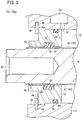
FIG. 3 is a partially enlarged vertical cross-sectional view showing a configuration of the fluid pressure cylinder according to a second example (a fluid pressure cylinder according to a first comparative example); -
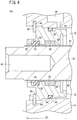
FIG. 4 is a partially enlarged vertical cross-sectional view showing a configuration of the fluid pressure cylinder according to a third example; -
FIG. 5 is a partially enlarged vertical cross-sectional view showing the configuration of a fluid pressure cylinder according to a second comparative example; -
FIG. 6 is a graph showing a minimum operating pressure plotted with respect to the number of times the piston is driven; and -
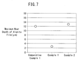
FIG. 7 is a graph showing a maximum wear depth of an alumite film after the piston was driven ten million times. - A description of a preferred embodiment in relation to a fluid pressure cylinder according to the present invention will be described with reference to the accompanying drawings.
- As shown in
FIG. 1 , a fluid pressure cylinder (sliding device) 10 according to an embodiment of the present invention is equipped with a cylindermain body 14 in which acylinder hole 12 is formed, apiston 16 disposed in thecylinder hole 12 and which is displaceable along an axial direction, apiston rod 18 connected to thepiston 16, and arod cover 22 disposed in the cylindermain body 14 and in which arod insertion hole 20 is formed through which thepiston rod 18 is inserted. - The cylinder
main body 14 can be constituted from an arbitrary material, and for example, is integrally formed in a bottomed cylindrical shape by aluminum or an aluminum alloy. However, the cylindermain body 14 may also be configured such that an opening on one side of a tube member, both ends of which are open, is closed by an end cover. - A
first port 24 and asecond port 26, which are connected to a fluid supply source via a flow path and a flow path switching device (not shown), open on an outer surface of the cylindermain body 14. Thefirst port 24 communicates through afirst communication passage 30 with afirst cylinder chamber 28 that is formed between thepiston 16 and the bottom surface of the cylindermain body 14. Thesecond port 26 communicates through asecond communication passage 34 with asecond cylinder chamber 32 that is formed between thepiston 16 and therod cover 22. - Although it can be constituted by an arbitrary material, the
piston 16, for example, is constituted in a cylindrical shape from aluminum or an aluminum alloy. Apiston packing 38 is installed through anannular groove 36 on an outer circumferential surface of thepiston 16. A magnet for detecting the position of thepiston 16 in the axial direction with respect to the cylindermain body 14 may be mounted on the outer circumferential surface of thepiston 16. In this case, a sensor attachment groove for attachment of a magnetic detection sensor for detecting magnetism from the magnet is formed on an outer surface of the cylindermain body 14. - The
piston rod 18 is formed in a cylindrical shape by aluminum or an aluminum alloy, and one end portion of thepiston rod 18 is connected to thepiston 16. Consequently, thepiston rod 18 is linked for movement together with thepiston 16. On another end surface of thepiston rod 18, which is exposed to the exterior of the cylindermain body 14 by insertion thereof through therod insertion hole 20, amounting hole 40 is formed for attaching a workpiece or the like. - A diamond-like carbon film (hereinafter referred to as a DLC film 42) is formed on the outer circumferential surface (outer wall surface) of the
piston rod 18. TheDLC film 42 is an amorphous hard film composed of an allotrope of hydrocarbon or carbon, which is excellent in lubricity, abrasion resistance, seizure resistance, etc. - The
DLC film 42 can be formed by a CVD (Chemical Vapor Deposition) method, a PVD (Physical Vapor Deposition) method, or the like environmentally friendly without discharging liquid waste. Further, in order to improve adhesion of theDLC film 42 with a substrate material (the piston rod 18), an intermediate layer may be formed between the substrate material and theDLC film 42. Such an intermediate layer can be constituted, for example, by a composite layer made up of DLC and the substrate material. In this case, as the composition ratio of metal in the intermediate layer becomes greater in closer proximity to the substrate material, the composition ratio of the DLC decreases, whereas on the other hand, as the composition ratio of metal becomes smaller as the distance from the substrate is greater, the composition ratio of the DLC increases. By using such an intermediate layer, peeling off of theDLC film 42 from the substrate material can suitably be suppressed. - The hardness of the
DLC film 42 increases as it moves away from the substrate material toward the side of the outer surface. More specifically, the Vickers hardness of theDLC film 42 in the vicinity of the substrate material is set to be less than or equal to 900 Hv, whereas the Vickers hardness of theDLC film 42 on the outermost surface is set to be greater than or equal to 1300 Hv. In accordance with this feature, peeling away of theDLC film 42 from the substrate material can more suitably be suppressed. Further, the surface roughness of theDLC film 42 is set to be less than or equal to 1.6 Rz. In accordance with this feature, abrasion and wear of a later-describedrod packing 52 can suitably be suppressed. - The
DLC film 42 is colored in a different color (for example, black) that differs from the color (metallic color) of aluminum or an aluminum alloy. In this case, it is easy to recognize visually whether theDLC film 42 has peeled off, thereby exposing the underlying aluminum or aluminum alloy. Thus, appropriate measures can be taken before the occurrence of equipment stoppage due to the service life of thefluid pressure cylinder 10. - The film thickness of the
DLC film 42 preferably is greater than or equal to 0.1 µm and less than or equal to 5.0 µm, more preferably, is greater than or equal to 0.3 µm and less than or equal to 4.0 µm, and even more preferably, is greater than or equal to 1.0 µm and less than or equal to 4.0 µm. This is because, if the film thickness of theDLC film 42 is less than 0.1 µm, there is a concern that theDLC film 42 will peel away rapidly due to wear and abrasion, whereas if the film thickness of theDLC film 42 is greater than 5.0 µm, formation of the film cannot be performed easily, which leads to a rise in cost. - The
rod cover 22 is formed in a circular ring-like shape by aluminum or an aluminum alloy, and supports thepiston rod 18 in a state of being disposed on the wall surface that constitutes thecylinder hole 12. Further, therod cover 22 is prevented from slipping out from thecylinder hole 12 by anannular retaining ring 46, which is attached via anannular groove 44 to the wall surface that constitutes thecylinder hole 12. - A
gasket 50 is installed through anannular groove 48 on an outer circumferential surface of therod cover 22. Anannular groove 54 in which the rod packing 52, which is made of a resin material such as urethane rubber, is installed, and a grease accommodating groove (grease reservoir) 56 in which grease (a lubricant) is accommodated are formed on the inner circumferential surface (inner wall surface) of therod cover 22. In the present embodiment, thegrease accommodating groove 56 is positioned more on the side of the retaining ring 46 (on an opposite side from the piston 16) than theannular groove 54. - On at least a portion of the inner circumferential surface of the
rod cover 22, analumite film 58 is formed that slides in contact with theDLC film 42. Thealumite film 58 preferably is a hard alumite film as described in JIS 8603. In this case, the abrasion resistance of thealumite film 58 can be further enhanced. However, there is no problem if thealumite film 58 is not the above-described hard alumite film. - The dimension along the axial direction of the
grease accommodating groove 56 is set so as to be greater than or equal to 1/5 and less than or equal to 4/5 of the sliding surface length dimension (the length dimension along the axial direction of thealumite film 58 that slides in contact with the DLC film 42). Consequently, grease can be supplied efficiently between theDLC film 42 and thealumite film 58 while appropriately suppressing the pressure that acts on thealumite film 58 from thepiston rod 18. - The
fluid pressure cylinder 10 according to the present embodiment is constructed basically in the manner described above. Next, operations and advantageous effects of thefluid pressure cylinder 10 will be described. As shown inFIG. 1 , a state in which thepiston 16 is positioned on a bottom surface side of the cylindermain body 14 will be described as an initial position. - In the initial position, when a working fluid (pressure fluid) is supplied to the
first port 24 from the fluid supply source in a state in which thesecond port 26 is opened to atmosphere by the fluid passage switching device, by an action of the working fluid that flows into thefirst cylinder chamber 28, thepiston 16 is displaced to the side of therod cover 22, together with the fluid that exists in thesecond cylinder chamber 32 being discharged to atmosphere through thesecond port 26. In addition, by thepiston 16 coming into contact with therod cover 22, displacement of thepiston 16 toward the side of therod cover 22 is stopped. - When a working fluid is supplied to the
second port 26 from the fluid supply source in a state in which thefirst port 24 is opened to atmosphere by the fluid passage switching device, by an action of the working fluid that flows into thesecond cylinder chamber 32, thepiston 16 is displaced to the bottom surface side of the cylindermain body 14, together with the fluid that exists in thefirst cylinder chamber 28 being discharged to atmosphere through thefirst port 24. In addition, by thepiston 16 coming into contact with the bottom surface of the cylindermain body 14, displacement of thepiston 16 toward the bottom surface side of the cylindermain body 14 is stopped. - According to the present embodiment, when the piston 16 (piston rod 18) is displaced in this manner along the axial direction, the
DLC film 42 and thealumite film 58 undergo sliding movement in a state in which the grease that is accommodated in thegrease accommodating groove 56 is supplied between theDLC film 42 that is formed on the outer circumferential surface of thepiston rod 18 and thealumite film 58 that is formed on the inner circumferential surface of therod cover 22. TheDLC film 42 possesses chemical stability and self-lubricity in order to prevent adhesion thereof with aluminum and alumite. Therefore, thepiston rod 18 is displaced in a state in which sliding wear and adhesive wear are suppressed. Consequently, it is possible to realize a long service life of thefluid pressure cylinder 10. - Further, in addition to constituting the
piston rod 18 and therod cover 22 from aluminum or an aluminum alloy, since there is no need to provide a copper bush in therod insertion hole 20, the number of component parts can be reduced, a reduction in weight can be achieved, and thefluid pressure cylinder 10 can be used even in a copper-based material non-usage environment. - Furthermore, since the
DLC film 42 is formed on the outer circumferential surface of thepiston rod 18, which is easier to coat than the inner circumferential surface constituting therod insertion hole 20, manufacturing costs for thefluid pressure cylinder 10 can be reduced. Further still, since thegrease accommodating groove 56 in which grease is accommodated is formed on the inner circumferential surface of therod cover 22, grease can be supplied between theDLC film 42 and thealumite film 58, and hence, sliding wear of therod cover 22 can be suppressed. Consequently, it is possible to prolong the service life of thefluid pressure cylinder 10. - The present embodiment is not limited to the configuration described above. For example, the
grease accommodating groove 56 may be dispensed with (refer toFIG. 3 ), or thegrease accommodating groove 56 may be formed more on the side of thepiston 16 than the rod packing 52 (refer toFIG. 4 ). Further, in the present embodiment, thealumite film 58 may be formed on the outer circumferential surface of thepiston rod 18, and theDLC film 42 that slides in contact with thealumite film 58 may be formed on the inner circumferential surface of therod cover 22. In this case as well, advantages and effects similar to those mentioned above can be obtained. - The present invention will be described in greater detail through presentation of the following examples of the present invention. Materials, configurations, film thicknesses, etc., as shown in the following examples can be appropriately modified without deviating from the essential gist of the present invention. Consequently, the technical scope of the present invention should not be interpreted restrictively by the following specific examples.
- First through third examples, and first and second comparative examples are shown in Table 1 appearing below.
TABLE 1 Example 1 Example 2 Example 3 Comparative Example 1 Comparative Example 2 Piston Rod Material A2017 A2017 A2017 S45C S45C Film DLC DLC DLC Hard Chromium Hard Chromium Film Thickness (µm) 1-2 1-2 1-2 8 8 Rod Cover Material A6061-T6 A6061-T6 A6061-T6 A6061-T6 A6061-T6 Film Hard Alumite Hard Alumite Hard Alumite Hard Alumite Hard Alumite Film Thickness (µm) 15 15 15 15 15 Rod Cover Length Dimension La La Lb La Lb Grease Accommodating Groove Present YES NO YES NO NO Bush Present NO NO NO NO YES - As shown in
FIG. 2 , afluid pressure cylinder 10a according to Example 1 was manufactured. Thefluid pressure cylinder 10a was constituted in the same manner as the aforementionedfluid pressure cylinder 10. More specifically, thepiston rod 18 was made of an aluminum alloy (A2017: JIS standard), and aDLC film 42 having a film thickness of 1 µm to 2 µm was formed on an outer circumferential surface of thepiston rod 18. Further, therod cover 22 was made of an aluminum alloy (A6061-T6: JIS standard). An alumite film (hard alumite film) 58 having a film thickness of 15 µm was formed on an inner circumferential surface of therod cover 22. The length dimension along the axial direction of therod cover 22 according to Example 1 is indicated by La. Moreover, the diameter of thepiston rod 18 was set to 16 mm, and the stroke of thepiston 16 was set to 50 mm. - As shown in
FIG. 3 , afluid pressure cylinder 10b according to Example 2 was manufactured. More specifically, thefluid pressure cylinder 10b according to Example 2 was produced in the same manner as in Example 1, except that thegrease accommodating groove 56 was omitted. - As shown in
FIG. 4 , afluid pressure cylinder 10c according to Example 3 was manufactured. In thefluid pressure cylinder 10c according to Example 3, the constituent materials of thepiston rod 18 and therod cover 22, the film thicknesses of theDLC film 42 and thealumite film 58, the diameter of thepiston rod 18, and the stroke of thepiston 16 are the same as those according to Example 1. Further, the length dimension along the axial direction of therod cover 22 according to Example 3 is indicated by Lb, which was longer than the length dimension La. Further, thegrease accommodating groove 56 was formed more on the side of thepiston 16 than the rod packing 52. - The
piston rod 18 was made of carbon steel (S45C: JIS standard), and apart from ahard chromium film 102 having a film thickness of 8 µm being formed on the outer circumferential surface of thepiston rod 18, thefluid pressure cylinder 100a according to Comparative Example 1 was manufactured in the same manner as Example 2 (refer toFIG. 3 ). - As shown in
FIG. 5 , afluid pressure cylinder 100b according to Comparative Example 2 was manufactured. With thefluid pressure cylinder 100b according to Comparative Example 2, abush installation groove 106 for installation therein of alead bronze bush 104 was formed, instead of thegrease accommodating groove 56 according to Example 3. Further, thepiston rod 18 and thehard chromium film 102 were formed in the same manner as in Comparative Example 1, and apart therefrom, thefluid pressure cylinder 100b was manufactured in the same manner as in Example 3. - The weights of the
fluid pressure cylinders - In the
fluid pressure cylinders alumite films 58 of Example 1, Example 2, and Comparative Example 1, after thepiston 16 was driven ten million times, were measured using a roundness measuring machine (ACCRETECH RONDCOM 60A) manufactured by Tokyo Seimitsu Co., Ltd. The measurement conditions were as follows: - Roundness Evaluation: maximum inscribed circle center method (MIC)
- Filter Type: 2 RC
- Measurement Method: semiautomatic measurement
- Measurement Speed: 5 mm/s
- Posture: vertical
- The weight measurement results are indicated in Table 2 below, and the service life measurement results are as shown in
FIGS. 6 and7 .TABLE 2 Example 1 Example 2 Example 3 Comparative Example 1 Comparative Example 2 Weight of Fluid Pressure Cylinder 230 g - 260 g 320 g 350 g - As indicated in Table 2, the weight of the
fluid pressure cylinder 100a according to Comparative Example 1 was 320 g, whereas the weight of thefluid pressure cylinder 10a according to Example 1 was 230 g. More specifically, by configuring thepiston rod 18 from an aluminum alloy, the weight of thefluid pressure cylinder 10a can be reduced by about 28% compared to the weight of thefluid pressure cylinder 100a. - Further, the weight of the
fluid pressure cylinder 100b according to Comparative Example 2 was 350 g, whereas the weight of thefluid pressure cylinder 10c according to Example 3 was 260 g. More specifically, by configuring thepiston rod 18 from an aluminum alloy together with eliminating thelead bronze bush 104, the weight of thefluid pressure cylinder 10c can be reduced by about 25% compared to the weight of thefluid pressure cylinder 100b. - Moreover, in the
fluid pressure cylinder 10c according to Example 3, since thegrease accommodating groove 56 is formed at a position where thebush 104 had been located in thefluid pressure cylinder 100b according to Comparative Example 2, thefluid pressure cylinder 10c is not increased in scale, even if thegrease accommodating groove 56 is formed therein. - Furthermore, as can be understood from
FIG. 6 , with thefluid pressure cylinder 100a according to Comparative Example 1, the minimum operating pressure rises rapidly when the number of times the piston was driven exceeds six million, whereas with thefluid pressure cylinders piston 16 has been driven ten million times, the minimum operating pressure of thefluid pressure cylinder 10a became lower than the minimum operating pressure of thefluid pressure cylinder 10b. Moreover, in thefluid pressure cylinders - In the foregoing manner, by forming the
DLC film 42 on the outer circumferential surface of thepiston rod 18, together with forming thealumite film 58 on the inner circumferential surface of therod cover 22, the minimum operating pressure could be suppressed and remain comparatively low, and the service life could be prolonged, even though the number of times the piston was driven ten million times was reached. Further, in the case that thegrease accommodating groove 56 was provided on the inner circumferential surface of therod cover 22, compared to the case of not providing thegrease accommodating groove 56, the minimum operating pressure at a time after thepiston 16 was driven ten million times could be lowered, and the service life could further be prolonged. - Further still, as can be understood from
FIG. 7 , the maximum wear depth of thefluid pressure cylinder 10a according to the first embodiment could be suppressed to about 1/4 the maximum wear depth of thealumite film 58 of thefluid pressure cylinder 100a according to Comparative Example 1, and the service life of thefluid pressure cylinder 10a could be prolonged even further. - The fluid pressure cylinder according to the present invention is not limited to the embodiment described above, and it is a matter of course that various modified or additional configurations could be adopted therein without deviating from the essential gist of the present invention.
Claims (4)
- A fluid pressure cylinder (10, 10a to 10c) comprising:a cylinder main body (14) in which a cylinder hole (32) is formed;a piston (16) disposed in the cylinder hole (32) and which is displaced along an axial direction under an action of a working fluid;a piston rod (18) connected to the piston (16); anda rod cover (22) in which a rod insertion hole (20) is formed through which the piston rod (18) is inserted;wherein the piston rod (18) and the rod cover (22) are constituted from aluminum or an aluminum alloy;an alumite film (58) or a diamond-like carbon film (42) is formed on at least a portion of an inner wall surface of the rod cover (22) constituting the rod insertion hole (20); andin the case that the alumite film (58) is formed on the inner wall surface of the rod cover (22), a diamond-like carbon film (42) that slides in contact with the alumite film (58) is formed on the piston rod (18), whereas in the case that the diamond-like carbon film (42) is formed on the inner wall surface of the rod cover (22), an alumite film (58) that slides in contact with the diamond-like carbon film (42) is formed on the piston rod (18).
- The fluid pressure cylinder (10, 10a to 10c) according to claim 1, wherein:the alumite film (58) is formed on the inner wall surface of the rod cover (22); andthe diamond-like carbon film (42) that slides in contact with the alumite film (58) is formed on an outer wall surface of the piston rod (18).
- The fluid pressure cylinder (10, 10a, 10c) according to claim 1, wherein an accommodating groove (56) in which a lubricant is accommodated is formed on the inner wall surface of the rod cover (22).
- The fluid pressure cylinder (10, 10a, 10c) according to claim 2, wherein an accommodating groove (56) in which a lubricant is accommodated is formed on the inner wall surface of the rod cover (22).
Applications Claiming Priority (2)
| Application Number | Priority Date | Filing Date | Title |
|---|---|---|---|
| JP2014185855A JP6222571B2 (en) | 2014-09-12 | 2014-09-12 | Fluid pressure cylinder |
| PCT/JP2015/073658 WO2016039123A1 (en) | 2014-09-12 | 2015-08-24 | Hydraulic cylinder |
Publications (3)
| Publication Number | Publication Date |
|---|---|
| EP3193025A1 true EP3193025A1 (en) | 2017-07-19 |
| EP3193025A4 EP3193025A4 (en) | 2018-05-16 |
| EP3193025B1 EP3193025B1 (en) | 2021-04-14 |
Family
ID=55458879
Family Applications (1)
| Application Number | Title | Priority Date | Filing Date |
|---|---|---|---|
| EP15840283.4A Active EP3193025B1 (en) | 2014-09-12 | 2015-08-24 | Hydraulic cylinder |
Country Status (10)
| Country | Link |
|---|---|
| US (1) | US10480546B2 (en) |
| EP (1) | EP3193025B1 (en) |
| JP (1) | JP6222571B2 (en) |
| KR (1) | KR101953641B1 (en) |
| CN (1) | CN106715927B (en) |
| BR (1) | BR112017004751B1 (en) |
| MX (1) | MX382338B (en) |
| RU (1) | RU2668300C2 (en) |
| TW (1) | TWI653400B (en) |
| WO (1) | WO2016039123A1 (en) |
Families Citing this family (2)
| Publication number | Priority date | Publication date | Assignee | Title |
|---|---|---|---|---|
| JP6647551B2 (en) * | 2015-10-14 | 2020-02-14 | Smc株式会社 | Fluid pressure device and manufacturing method thereof |
| US11867205B2 (en) * | 2016-07-29 | 2024-01-09 | Industries Malhot Inc. | Cylinder piston rod and method of fabrication thereof |
Family Cites Families (22)
| Publication number | Priority date | Publication date | Assignee | Title |
|---|---|---|---|---|
| US3339932A (en) * | 1965-03-01 | 1967-09-05 | Parker Hannifin Corp | Sealing apparatus |
| JPS6035812Y2 (en) * | 1979-11-09 | 1985-10-24 | トキコ株式会社 | gas spring |
| JPH02253003A (en) * | 1989-03-27 | 1990-10-11 | Taiyo Ltd | Nonlubricated fluid pressure cylinder |
| DE59307522D1 (en) | 1993-07-14 | 1997-11-13 | Guenter Weber | METHOD FOR PRODUCING PISTON AND PISTON RODS AND CYLINDERS FOR HYDRAULIC OR PNEUMATIC UNITS |
| US5983778A (en) * | 1997-07-28 | 1999-11-16 | Dawson Hydraulics, Inc. | Telescopic hydraulic hoist apparatus |
| JPH11105790A (en) | 1997-09-30 | 1999-04-20 | Showa Corp | Tilt and trim system for marine propulsion |
| US5974948A (en) * | 1998-01-29 | 1999-11-02 | Zaytran, Inc. | Linear actuator |
| JP2001107860A (en) * | 1999-10-07 | 2001-04-17 | Matsushita Refrig Co Ltd | Sliding member |
| CN1084266C (en) | 1999-11-29 | 2002-05-08 | 范勇 | Automobile shock absorber with oil groove and connection guide sandwiched between upper and lower oil seals |
| JP4505928B2 (en) | 2000-02-29 | 2010-07-21 | 株式会社アドヴィックス | Wheel cylinder |
| RU2209351C1 (en) * | 2002-03-04 | 2003-07-27 | Козлов Александр Николаевич | Pneumatic cylinder |
| JP2005127417A (en) * | 2003-10-23 | 2005-05-19 | Smc Corp | Lubrication structure of hydraulic drive unit |
| CN1975194A (en) * | 2006-12-11 | 2007-06-06 | 杨德君 | Gas spring |
| JP5212773B2 (en) * | 2007-09-11 | 2013-06-19 | Smc株式会社 | Fluid pressure cylinder |
| US8690128B1 (en) | 2008-07-23 | 2014-04-08 | Lippert Components Manufacturing, Inc. | Hydraulic leveling cylinder |
| JP5433897B2 (en) | 2009-10-22 | 2014-03-05 | 好孝 光田 | Diamond-like carbon film forming member and method for producing the same |
| JP5338695B2 (en) * | 2010-02-02 | 2013-11-13 | Smc株式会社 | Fluid pressure cylinder dust removal mechanism |
| DE102010022207A1 (en) | 2010-05-20 | 2011-11-24 | Robert Bosch Gmbh | Pressure medium cylinder, particularly pneumatic cylinders or hydraulic cylinders, comprises piston, which is movably housed in cylinder housing axially by one-sided pressure medium application |
| JP5543887B2 (en) * | 2010-09-28 | 2014-07-09 | 株式会社ショーワ | Anti-corrosion structure for ship propulsion equipment |
| JP5862098B2 (en) * | 2011-08-04 | 2016-02-16 | Smc株式会社 | Fluid pressure cylinder |
| JP2014059000A (en) | 2012-09-14 | 2014-04-03 | Ihi Corp | Slide structure and method for manufacturing the same |
| KR101454550B1 (en) * | 2013-06-28 | 2014-10-27 | 엘지전자 주식회사 | A linear compressor |
-
2014
- 2014-09-12 JP JP2014185855A patent/JP6222571B2/en active Active
-
2015
- 2015-08-24 WO PCT/JP2015/073658 patent/WO2016039123A1/en not_active Ceased
- 2015-08-24 BR BR112017004751-9A patent/BR112017004751B1/en active IP Right Grant
- 2015-08-24 CN CN201580048754.7A patent/CN106715927B/en active Active
- 2015-08-24 RU RU2017107872A patent/RU2668300C2/en active
- 2015-08-24 US US15/509,651 patent/US10480546B2/en active Active
- 2015-08-24 KR KR1020177009795A patent/KR101953641B1/en active Active
- 2015-08-24 MX MX2017002857A patent/MX382338B/en unknown
- 2015-08-24 EP EP15840283.4A patent/EP3193025B1/en active Active
- 2015-08-25 TW TW104127644A patent/TWI653400B/en active
Also Published As
| Publication number | Publication date |
|---|---|
| TW201621175A (en) | 2016-06-16 |
| KR20170052680A (en) | 2017-05-12 |
| RU2017107872A3 (en) | 2018-09-10 |
| RU2668300C2 (en) | 2018-09-28 |
| BR112017004751B1 (en) | 2022-05-24 |
| CN106715927B (en) | 2018-08-03 |
| WO2016039123A1 (en) | 2016-03-17 |
| TWI653400B (en) | 2019-03-11 |
| BR112017004751A2 (en) | 2018-06-26 |
| MX382338B (en) | 2025-03-13 |
| RU2017107872A (en) | 2018-09-10 |
| JP6222571B2 (en) | 2017-11-01 |
| CN106715927A (en) | 2017-05-24 |
| US10480546B2 (en) | 2019-11-19 |
| US20170284428A1 (en) | 2017-10-05 |
| EP3193025B1 (en) | 2021-04-14 |
| EP3193025A4 (en) | 2018-05-16 |
| MX2017002857A (en) | 2017-05-30 |
| JP2016056923A (en) | 2016-04-21 |
| KR101953641B1 (en) | 2019-03-04 |
Similar Documents
| Publication | Publication Date | Title |
|---|---|---|
| KR20120042769A (en) | Sliding element, in particular a piston ring, having a coating | |
| JP5311652B2 (en) | Ballpoint pen tip | |
| US8840115B2 (en) | Wide range temperature and pressure hydraulic cylinder sealing system | |
| ES2327793T3 (en) | BOARD IN HIGH PRESSURE DEVICES. | |
| JP6518064B2 (en) | Sliding seal structure | |
| US10480546B2 (en) | Hydraulic cylinder | |
| US20060054438A1 (en) | Guide-equipped cylinder | |
| US20200378411A1 (en) | A cylinder piston rod and method of fabrication thereof | |
| EP3575628A1 (en) | Shock absorber and method for manufacturing sliding member | |
| US20050236060A1 (en) | Multilayer plated fuel line parts for automobile | |
| EP3556900B1 (en) | Corrosion-resistant member | |
| US20170175622A1 (en) | Sliding element | |
| US20100206163A1 (en) | Wear resistance reinforcing method and sliding structure | |
| WO2003042548A1 (en) | Hydraulic and pneumatic cylinders with polymer coating | |
| CN104379928B (en) | High-pressure pump for fuel injection system | |
| JP2006105391A (en) | Cylinder with guide | |
| EP3477136B1 (en) | Air bearing | |
| US10941829B2 (en) | Damper system with a high performance plastic wiper seal | |
| CN218018283U (en) | Sealing ring replacing tool of chip laminating machine | |
| CN206309845U (en) | Rod protection device and the damper with rod protection device | |
| KR102021714B1 (en) | Pneumatic brake booster with metal coated booster housing | |
| JP2006199171A5 (en) | ||
| Kaiser | Glass seal | |
| TH89457B (en) | Synthetic resin coated aluminum sheet and molded products using this |
Legal Events
| Date | Code | Title | Description |
|---|---|---|---|
| STAA | Information on the status of an ep patent application or granted ep patent |
Free format text: STATUS: THE INTERNATIONAL PUBLICATION HAS BEEN MADE |
|
| PUAI | Public reference made under article 153(3) epc to a published international application that has entered the european phase |
Free format text: ORIGINAL CODE: 0009012 |
|
| STAA | Information on the status of an ep patent application or granted ep patent |
Free format text: STATUS: REQUEST FOR EXAMINATION WAS MADE |
|
| 17P | Request for examination filed |
Effective date: 20170308 |
|
| AK | Designated contracting states |
Kind code of ref document: A1 Designated state(s): AL AT BE BG CH CY CZ DE DK EE ES FI FR GB GR HR HU IE IS IT LI LT LU LV MC MK MT NL NO PL PT RO RS SE SI SK SM TR |
|
| AX | Request for extension of the european patent |
Extension state: BA ME |
|
| DAV | Request for validation of the european patent (deleted) | ||
| DAX | Request for extension of the european patent (deleted) | ||
| A4 | Supplementary search report drawn up and despatched |
Effective date: 20180417 |
|
| RIC1 | Information provided on ipc code assigned before grant |
Ipc: F16J 7/00 20060101ALI20180409BHEP Ipc: F15B 15/14 20060101AFI20180409BHEP |
|
| GRAP | Despatch of communication of intention to grant a patent |
Free format text: ORIGINAL CODE: EPIDOSNIGR1 |
|
| STAA | Information on the status of an ep patent application or granted ep patent |
Free format text: STATUS: GRANT OF PATENT IS INTENDED |
|
| INTG | Intention to grant announced |
Effective date: 20201214 |
|
| GRAS | Grant fee paid |
Free format text: ORIGINAL CODE: EPIDOSNIGR3 |
|
| GRAA | (expected) grant |
Free format text: ORIGINAL CODE: 0009210 |
|
| STAA | Information on the status of an ep patent application or granted ep patent |
Free format text: STATUS: THE PATENT HAS BEEN GRANTED |
|
| AK | Designated contracting states |
Kind code of ref document: B1 Designated state(s): AL AT BE BG CH CY CZ DE DK EE ES FI FR GB GR HR HU IE IS IT LI LT LU LV MC MK MT NL NO PL PT RO RS SE SI SK SM TR |
|
| REG | Reference to a national code |
Ref country code: GB Ref legal event code: FG4D |
|
| REG | Reference to a national code |
Ref country code: CH Ref legal event code: EP |
|
| REG | Reference to a national code |
Ref country code: DE Ref legal event code: R096 Ref document number: 602015068210 Country of ref document: DE |
|
| REG | Reference to a national code |
Ref country code: IE Ref legal event code: FG4D |
|
| REG | Reference to a national code |
Ref country code: AT Ref legal event code: REF Ref document number: 1382631 Country of ref document: AT Kind code of ref document: T Effective date: 20210515 |
|
| REG | Reference to a national code |
Ref country code: LT Ref legal event code: MG9D |
|
| REG | Reference to a national code |
Ref country code: AT Ref legal event code: MK05 Ref document number: 1382631 Country of ref document: AT Kind code of ref document: T Effective date: 20210414 |
|
| REG | Reference to a national code |
Ref country code: NL Ref legal event code: MP Effective date: 20210414 |
|
| PG25 | Lapsed in a contracting state [announced via postgrant information from national office to epo] |
Ref country code: AT Free format text: LAPSE BECAUSE OF FAILURE TO SUBMIT A TRANSLATION OF THE DESCRIPTION OR TO PAY THE FEE WITHIN THE PRESCRIBED TIME-LIMIT Effective date: 20210414 Ref country code: BG Free format text: LAPSE BECAUSE OF FAILURE TO SUBMIT A TRANSLATION OF THE DESCRIPTION OR TO PAY THE FEE WITHIN THE PRESCRIBED TIME-LIMIT Effective date: 20210714 Ref country code: HR Free format text: LAPSE BECAUSE OF FAILURE TO SUBMIT A TRANSLATION OF THE DESCRIPTION OR TO PAY THE FEE WITHIN THE PRESCRIBED TIME-LIMIT Effective date: 20210414 Ref country code: FI Free format text: LAPSE BECAUSE OF FAILURE TO SUBMIT A TRANSLATION OF THE DESCRIPTION OR TO PAY THE FEE WITHIN THE PRESCRIBED TIME-LIMIT Effective date: 20210414 Ref country code: NL Free format text: LAPSE BECAUSE OF FAILURE TO SUBMIT A TRANSLATION OF THE DESCRIPTION OR TO PAY THE FEE WITHIN THE PRESCRIBED TIME-LIMIT Effective date: 20210414 Ref country code: LT Free format text: LAPSE BECAUSE OF FAILURE TO SUBMIT A TRANSLATION OF THE DESCRIPTION OR TO PAY THE FEE WITHIN THE PRESCRIBED TIME-LIMIT Effective date: 20210414 |
|
| PG25 | Lapsed in a contracting state [announced via postgrant information from national office to epo] |
Ref country code: IS Free format text: LAPSE BECAUSE OF FAILURE TO SUBMIT A TRANSLATION OF THE DESCRIPTION OR TO PAY THE FEE WITHIN THE PRESCRIBED TIME-LIMIT Effective date: 20210814 Ref country code: GR Free format text: LAPSE BECAUSE OF FAILURE TO SUBMIT A TRANSLATION OF THE DESCRIPTION OR TO PAY THE FEE WITHIN THE PRESCRIBED TIME-LIMIT Effective date: 20210715 Ref country code: LV Free format text: LAPSE BECAUSE OF FAILURE TO SUBMIT A TRANSLATION OF THE DESCRIPTION OR TO PAY THE FEE WITHIN THE PRESCRIBED TIME-LIMIT Effective date: 20210414 Ref country code: NO Free format text: LAPSE BECAUSE OF FAILURE TO SUBMIT A TRANSLATION OF THE DESCRIPTION OR TO PAY THE FEE WITHIN THE PRESCRIBED TIME-LIMIT Effective date: 20210714 Ref country code: PT Free format text: LAPSE BECAUSE OF FAILURE TO SUBMIT A TRANSLATION OF THE DESCRIPTION OR TO PAY THE FEE WITHIN THE PRESCRIBED TIME-LIMIT Effective date: 20210816 Ref country code: PL Free format text: LAPSE BECAUSE OF FAILURE TO SUBMIT A TRANSLATION OF THE DESCRIPTION OR TO PAY THE FEE WITHIN THE PRESCRIBED TIME-LIMIT Effective date: 20210414 Ref country code: RS Free format text: LAPSE BECAUSE OF FAILURE TO SUBMIT A TRANSLATION OF THE DESCRIPTION OR TO PAY THE FEE WITHIN THE PRESCRIBED TIME-LIMIT Effective date: 20210414 Ref country code: SE Free format text: LAPSE BECAUSE OF FAILURE TO SUBMIT A TRANSLATION OF THE DESCRIPTION OR TO PAY THE FEE WITHIN THE PRESCRIBED TIME-LIMIT Effective date: 20210414 |
|
| REG | Reference to a national code |
Ref country code: DE Ref legal event code: R097 Ref document number: 602015068210 Country of ref document: DE |
|
| PG25 | Lapsed in a contracting state [announced via postgrant information from national office to epo] |
Ref country code: RO Free format text: LAPSE BECAUSE OF FAILURE TO SUBMIT A TRANSLATION OF THE DESCRIPTION OR TO PAY THE FEE WITHIN THE PRESCRIBED TIME-LIMIT Effective date: 20210414 Ref country code: ES Free format text: LAPSE BECAUSE OF FAILURE TO SUBMIT A TRANSLATION OF THE DESCRIPTION OR TO PAY THE FEE WITHIN THE PRESCRIBED TIME-LIMIT Effective date: 20210414 Ref country code: SK Free format text: LAPSE BECAUSE OF FAILURE TO SUBMIT A TRANSLATION OF THE DESCRIPTION OR TO PAY THE FEE WITHIN THE PRESCRIBED TIME-LIMIT Effective date: 20210414 Ref country code: SM Free format text: LAPSE BECAUSE OF FAILURE TO SUBMIT A TRANSLATION OF THE DESCRIPTION OR TO PAY THE FEE WITHIN THE PRESCRIBED TIME-LIMIT Effective date: 20210414 Ref country code: DK Free format text: LAPSE BECAUSE OF FAILURE TO SUBMIT A TRANSLATION OF THE DESCRIPTION OR TO PAY THE FEE WITHIN THE PRESCRIBED TIME-LIMIT Effective date: 20210414 Ref country code: CZ Free format text: LAPSE BECAUSE OF FAILURE TO SUBMIT A TRANSLATION OF THE DESCRIPTION OR TO PAY THE FEE WITHIN THE PRESCRIBED TIME-LIMIT Effective date: 20210414 Ref country code: EE Free format text: LAPSE BECAUSE OF FAILURE TO SUBMIT A TRANSLATION OF THE DESCRIPTION OR TO PAY THE FEE WITHIN THE PRESCRIBED TIME-LIMIT Effective date: 20210414 |
|
| PLBE | No opposition filed within time limit |
Free format text: ORIGINAL CODE: 0009261 |
|
| STAA | Information on the status of an ep patent application or granted ep patent |
Free format text: STATUS: NO OPPOSITION FILED WITHIN TIME LIMIT |
|
| 26N | No opposition filed |
Effective date: 20220117 |
|
| REG | Reference to a national code |
Ref country code: CH Ref legal event code: PL |
|
| PG25 | Lapsed in a contracting state [announced via postgrant information from national office to epo] |
Ref country code: MC Free format text: LAPSE BECAUSE OF FAILURE TO SUBMIT A TRANSLATION OF THE DESCRIPTION OR TO PAY THE FEE WITHIN THE PRESCRIBED TIME-LIMIT Effective date: 20210414 |
|
| REG | Reference to a national code |
Ref country code: BE Ref legal event code: MM Effective date: 20210831 |
|
| GBPC | Gb: european patent ceased through non-payment of renewal fee |
Effective date: 20210824 |
|
| PG25 | Lapsed in a contracting state [announced via postgrant information from national office to epo] |
Ref country code: LI Free format text: LAPSE BECAUSE OF NON-PAYMENT OF DUE FEES Effective date: 20210831 Ref country code: CH Free format text: LAPSE BECAUSE OF NON-PAYMENT OF DUE FEES Effective date: 20210831 |
|
| PG25 | Lapsed in a contracting state [announced via postgrant information from national office to epo] |
Ref country code: IS Free format text: LAPSE BECAUSE OF FAILURE TO SUBMIT A TRANSLATION OF THE DESCRIPTION OR TO PAY THE FEE WITHIN THE PRESCRIBED TIME-LIMIT Effective date: 20210814 Ref country code: LU Free format text: LAPSE BECAUSE OF NON-PAYMENT OF DUE FEES Effective date: 20210824 Ref country code: AL Free format text: LAPSE BECAUSE OF FAILURE TO SUBMIT A TRANSLATION OF THE DESCRIPTION OR TO PAY THE FEE WITHIN THE PRESCRIBED TIME-LIMIT Effective date: 20210414 |
|
| PG25 | Lapsed in a contracting state [announced via postgrant information from national office to epo] |
Ref country code: IT Free format text: LAPSE BECAUSE OF FAILURE TO SUBMIT A TRANSLATION OF THE DESCRIPTION OR TO PAY THE FEE WITHIN THE PRESCRIBED TIME-LIMIT Effective date: 20210414 Ref country code: IE Free format text: LAPSE BECAUSE OF NON-PAYMENT OF DUE FEES Effective date: 20210824 Ref country code: GB Free format text: LAPSE BECAUSE OF NON-PAYMENT OF DUE FEES Effective date: 20210824 Ref country code: FR Free format text: LAPSE BECAUSE OF NON-PAYMENT OF DUE FEES Effective date: 20210831 Ref country code: BE Free format text: LAPSE BECAUSE OF NON-PAYMENT OF DUE FEES Effective date: 20210831 |
|
| PG25 | Lapsed in a contracting state [announced via postgrant information from national office to epo] |
Ref country code: HU Free format text: LAPSE BECAUSE OF FAILURE TO SUBMIT A TRANSLATION OF THE DESCRIPTION OR TO PAY THE FEE WITHIN THE PRESCRIBED TIME-LIMIT; INVALID AB INITIO Effective date: 20150824 |
|
| PG25 | Lapsed in a contracting state [announced via postgrant information from national office to epo] |
Ref country code: CY Free format text: LAPSE BECAUSE OF FAILURE TO SUBMIT A TRANSLATION OF THE DESCRIPTION OR TO PAY THE FEE WITHIN THE PRESCRIBED TIME-LIMIT Effective date: 20210414 |
|
| PG25 | Lapsed in a contracting state [announced via postgrant information from national office to epo] |
Ref country code: MK Free format text: LAPSE BECAUSE OF FAILURE TO SUBMIT A TRANSLATION OF THE DESCRIPTION OR TO PAY THE FEE WITHIN THE PRESCRIBED TIME-LIMIT Effective date: 20210414 |
|
| PG25 | Lapsed in a contracting state [announced via postgrant information from national office to epo] |
Ref country code: MT Free format text: LAPSE BECAUSE OF FAILURE TO SUBMIT A TRANSLATION OF THE DESCRIPTION OR TO PAY THE FEE WITHIN THE PRESCRIBED TIME-LIMIT Effective date: 20210414 |
|
| PGFP | Annual fee paid to national office [announced via postgrant information from national office to epo] |
Ref country code: DE Payment date: 20250919 Year of fee payment: 11 |
|
| PG25 | Lapsed in a contracting state [announced via postgrant information from national office to epo] |
Ref country code: TR Free format text: LAPSE BECAUSE OF FAILURE TO SUBMIT A TRANSLATION OF THE DESCRIPTION OR TO PAY THE FEE WITHIN THE PRESCRIBED TIME-LIMIT Effective date: 20210414 |