EP3192607A1 - Arc welding control method - Google Patents
Arc welding control method Download PDFInfo
- Publication number
- EP3192607A1 EP3192607A1 EP15840237.0A EP15840237A EP3192607A1 EP 3192607 A1 EP3192607 A1 EP 3192607A1 EP 15840237 A EP15840237 A EP 15840237A EP 3192607 A1 EP3192607 A1 EP 3192607A1
- Authority
- EP
- European Patent Office
- Prior art keywords
- period
- feeding
- welding
- reverse
- transient
- Prior art date
- Legal status (The legal status is an assumption and is not a legal conclusion. Google has not performed a legal analysis and makes no representation as to the accuracy of the status listed.)
- Granted
Links
Images




Classifications
-
- B—PERFORMING OPERATIONS; TRANSPORTING
- B23—MACHINE TOOLS; METAL-WORKING NOT OTHERWISE PROVIDED FOR
- B23K—SOLDERING OR UNSOLDERING; WELDING; CLADDING OR PLATING BY SOLDERING OR WELDING; CUTTING BY APPLYING HEAT LOCALLY, e.g. FLAME CUTTING; WORKING BY LASER BEAM
- B23K9/00—Arc welding or cutting
- B23K9/06—Arrangements or circuits for starting the arc, e.g. by generating ignition voltage, or for stabilising the arc
- B23K9/067—Starting the arc
- B23K9/0671—Starting the arc by means of brief contacts between the electrodes
-
- B—PERFORMING OPERATIONS; TRANSPORTING
- B23—MACHINE TOOLS; METAL-WORKING NOT OTHERWISE PROVIDED FOR
- B23K—SOLDERING OR UNSOLDERING; WELDING; CLADDING OR PLATING BY SOLDERING OR WELDING; CUTTING BY APPLYING HEAT LOCALLY, e.g. FLAME CUTTING; WORKING BY LASER BEAM
- B23K9/00—Arc welding or cutting
- B23K9/12—Automatic feeding or moving of electrodes or work for spot or seam welding or cutting
- B23K9/124—Circuits or methods for feeding welding wire
- B23K9/125—Feeding of electrodes
-
- B—PERFORMING OPERATIONS; TRANSPORTING
- B23—MACHINE TOOLS; METAL-WORKING NOT OTHERWISE PROVIDED FOR
- B23K—SOLDERING OR UNSOLDERING; WELDING; CLADDING OR PLATING BY SOLDERING OR WELDING; CUTTING BY APPLYING HEAT LOCALLY, e.g. FLAME CUTTING; WORKING BY LASER BEAM
- B23K9/00—Arc welding or cutting
-
- B—PERFORMING OPERATIONS; TRANSPORTING
- B23—MACHINE TOOLS; METAL-WORKING NOT OTHERWISE PROVIDED FOR
- B23K—SOLDERING OR UNSOLDERING; WELDING; CLADDING OR PLATING BY SOLDERING OR WELDING; CUTTING BY APPLYING HEAT LOCALLY, e.g. FLAME CUTTING; WORKING BY LASER BEAM
- B23K9/00—Arc welding or cutting
- B23K9/06—Arrangements or circuits for starting the arc, e.g. by generating ignition voltage, or for stabilising the arc
- B23K9/073—Stabilising the arc
-
- B—PERFORMING OPERATIONS; TRANSPORTING
- B23—MACHINE TOOLS; METAL-WORKING NOT OTHERWISE PROVIDED FOR
- B23K—SOLDERING OR UNSOLDERING; WELDING; CLADDING OR PLATING BY SOLDERING OR WELDING; CUTTING BY APPLYING HEAT LOCALLY, e.g. FLAME CUTTING; WORKING BY LASER BEAM
- B23K9/00—Arc welding or cutting
- B23K9/09—Arrangements or circuits for arc welding with pulsed current or voltage
- B23K9/091—Arrangements or circuits for arc welding with pulsed current or voltage characterised by the circuits
-
- B—PERFORMING OPERATIONS; TRANSPORTING
- B23—MACHINE TOOLS; METAL-WORKING NOT OTHERWISE PROVIDED FOR
- B23K—SOLDERING OR UNSOLDERING; WELDING; CLADDING OR PLATING BY SOLDERING OR WELDING; CUTTING BY APPLYING HEAT LOCALLY, e.g. FLAME CUTTING; WORKING BY LASER BEAM
- B23K9/00—Arc welding or cutting
- B23K9/095—Monitoring or automatic control of welding parameters
-
- B—PERFORMING OPERATIONS; TRANSPORTING
- B23—MACHINE TOOLS; METAL-WORKING NOT OTHERWISE PROVIDED FOR
- B23K—SOLDERING OR UNSOLDERING; WELDING; CLADDING OR PLATING BY SOLDERING OR WELDING; CUTTING BY APPLYING HEAT LOCALLY, e.g. FLAME CUTTING; WORKING BY LASER BEAM
- B23K9/00—Arc welding or cutting
- B23K9/12—Automatic feeding or moving of electrodes or work for spot or seam welding or cutting
-
- B—PERFORMING OPERATIONS; TRANSPORTING
- B23—MACHINE TOOLS; METAL-WORKING NOT OTHERWISE PROVIDED FOR
- B23K—SOLDERING OR UNSOLDERING; WELDING; CLADDING OR PLATING BY SOLDERING OR WELDING; CUTTING BY APPLYING HEAT LOCALLY, e.g. FLAME CUTTING; WORKING BY LASER BEAM
- B23K9/00—Arc welding or cutting
- B23K9/12—Automatic feeding or moving of electrodes or work for spot or seam welding or cutting
- B23K9/124—Circuits or methods for feeding welding wire
-
- B—PERFORMING OPERATIONS; TRANSPORTING
- B23—MACHINE TOOLS; METAL-WORKING NOT OTHERWISE PROVIDED FOR
- B23K—SOLDERING OR UNSOLDERING; WELDING; CLADDING OR PLATING BY SOLDERING OR WELDING; CUTTING BY APPLYING HEAT LOCALLY, e.g. FLAME CUTTING; WORKING BY LASER BEAM
- B23K9/00—Arc welding or cutting
- B23K9/16—Arc welding or cutting making use of shielding gas
- B23K9/173—Arc welding or cutting making use of shielding gas and of a consumable electrode
Definitions
- the present invention relates to an arc welding control method of performing a forward/reverse feeding control of alternating a feeding rate of a welding wire between a forward feeding period and a reverse feeding period, and generating short-circuiting periods and arc periods to perform welding.
- a typical consumable electrode arc welding welding is performed by feeding a welding wire as a consumable electrode at a constant feeding rate and generating an arc between the welding wire and base material.
- both the welding wire and the base material are mostly placed in a welding state in which a short-circuiting period and an arc period are alternately repeated.
- an average value of the feeding rate is adjusted according to a welding current setting value, and a repetition frequency and an amplitude of the forward feeding and the reverse feeding of the welding wire are adjusted to respective values according to the welding current setting value.
- Patent Document 1 Japanese Patent No. 5201266 B
- an object of the present invention is to provide an arc welding control method which, in welding of alternating a feeding rate between a forward feeding period and a reverse feeding period, can stabilize a welding state during a transient welding period from start of welding to convergence to a steady welding period.
- an arc welding control method of performing a forward/reverse feeding control of alternating a feeding rate of a welding wire between a forward feeding period and a reverse feeding period, and generating short-circuiting periods and arc periods to perform welding comprising: feeding the welding wire forwardly at a time of starting the welding; and starting the forward/reverse feeding control from the reverse feeding period of the welding wire after starting conduction of a welding current.
- the arc welding control method further comprising: during a transient welding period until convergence to a steady welding period, shifting the feeding rate to the forward feeding period responding to start of the arc period in the reverse feeding period, and shifting the feeding rate to the reverse feeding period responding to start of the short-circuiting period in the forward feeding period.
- the transient welding period is defined as a period from the start of conduction of the welding current to termination of the forward feeding period or the reverse feeding period after elapsing a predetermined period.
- the transient welding period is defined as a period from the start of conduction of the welding current to termination of a predetermined number of the forward feeding periods or a predetermined number of the reverse feeding periods.
- the arc welding control method further comprising: setting a waveform parameter of the feeding rate during the transient welding period to a value different from that during the steady welding period.
- the arc welding control method further comprising: setting an average value of the feeding rate during the transient welding period to a value different from that during the steady welding period.
- the arc welding control method further comprising: setting an amplitude of the feeding rate during the transient welding period to a value different from that during the steady welding period.
- the arc welding control method further comprising: setting a forward feeding amplitude of the feeding rate during the transient welding period to a value smaller than that during the steady welding period.
- a push-side feeding motor for performing a forward feeding control is provided in addition to a pull-side feeding motor for performing the forward/reverse feeding control, and the push-side feeding motor accelerates with an inclination after starting the conduction of welding current.
- the forward/reverse feeding control which is different from the control during the steady welding period, is performed during the transient welding period from the start of welding to the convergence to the steady welding period.
- the welding state during the transient welding period can be stabilized.
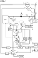
- Fig. 1 is a block diagram illustrating a welding power supply for implementing an arc welding control method according to a first embodiment of the present invention. Hereinafter individual blocks will be explained with reference to this figure.
- a power supply main circuit PM subjects the input power to an output control such as an inverter control according to a drive signal Dv described later, and outputs an output voltage E.
- this power supply main circuit PM includes a primary rectifier for rectifying the commercial power supply, a smoothing capacitor for smoothing the rectified DC, an inverter circuit which is driven by the drive signal Dv and converts the smoothed DC into a high-frequency AC, a high-frequency transformer for stepping down the high-frequency AC to a voltage value suitable for welding, and a secondary rectifier for rectifying the stepped-down high-frequency AC to a DC.
- a reactor WL smooths the output voltage E.
- An inductance value of the reactor WL is, for example, 200 ⁇ H.
- a feeding motor WM feeds a welding wire 1 at a feeding rate Fw in a manner of alternating forward feeding and reverse feeding cyclically.
- a motor having high transient responsiveness is used as the feeding motor WM.
- the feeding motor WM is installed near a tip of a welding torch 4 in order to increase a changing rate of the feeding rate Fw and an inversion speed of the feeding direction of the welding wire 1.
- a push-pull feeding system is employed by using two feeding motors WM.
- the welding wire 1 is fed within the welding torch 4 in accordance with rotation of a feeding roll 5 coupled to the feeding motor WM, and thus an arc 3 is generated between the welding wire and base material 2.
- a welding voltage Vw is applied between a power supply tip (not shown) within the welding torch 4 and the base material 2, and thus a welding current Iw flows.
- An output voltage setting circuit ER outputs an output voltage setting signal Er set in advance.
- An output voltage detection circuit ED detects and smooths the output voltage E, thereby outputting an output voltage detection signal Ed.
- a voltage error amplifier circuit EV amplifies an error between the output voltage setting signal Er (+) and the output voltage detection signal Ed (-) and outputs a voltage error amplified signal Ev. This circuit controls the welding power supply to a constant voltage.
- a hot-start current setting circuit IHR outputs a predetermined hot-start current setting signal
- a current detection circuit ID detects the welding current Iw and outputs a current detection signal Id.
- a current error amplifier circuit EI amplifies an error between the hot-start current setting signal Ali ( ⁇ ) and the current detection signal Id (-) and outputs a current error amplified signal Ei.
- This circuit controls the welding power supply to a constant current during a period (hot-start period) in which the hot-start current flows.
- a current-conduction discrimination circuit CD discriminates that the welding current Iw flows when a value of the current detection signal is a threshold value (about 10V) or more and outputs a current-conduction discrimination signal Cd.
- a power-supply characteristic switching circuit SW uses the current error amplified signal Ei, the voltage error amplified signal Ev and the current-conduction discrimination signal Cd as input, a power-supply characteristic switching circuit SW outputs the current error amplified signal Ei as an error amplified signal Ea during the predetermined hot-start period from a time where the current-conduction discrimination signal Cd changes to a high level (current conduction), whilst outputs the voltage error amplified signal Ev as the error amplified signal Ea during the other period.
- a voltage detection circuit VD detects the welding voltage Vw and outputs a voltage detection signal Vd. Using the voltage detection signal Vd as input, a short-circuit discrimination circuit SD outputs a short-circuit discrimination signal Sd. In a case where a value of the voltage detection signal is less than a short-circuit discrimination value (about 10V), the discrimination circuit determines to be a short-circuiting period and outputs the discrimination signal of a high level. In a case where a value of the voltage detection signal is the short-circuit discrimination value or more, the discrimination circuit determines to be an arc period and outputs the discrimination signal of a low level.
- a welding start circuit ST outputs a welding start signal St which becomes a high level when the welding power supply is activated.
- This welding start circuit ST corresponds to a start switch of the welding torch 4, a PLC for controlling a welding process, a robot control device or the like.
- a driving circuit DV uses the voltage error amplified signal Ea and the welding start signal St as input, a driving circuit DV performs a PWM modulation control based on the error amplified signal Ea when the welding start signal St is at the high level (welding start), and outputs the drive signal Dv for driving the inverter circuit within the power supply main circuit PM.
- a transient welding-period timer circuit STK selectively performs one of the following processing 1) to 4) and outputs a transient welding-period timer signal Stk. 1) Outputting the transient welding-period timer signal Stk which is set to a high level at a time where the current-conduction discrimination signal Cd changes to the high level (current conduction), and reset to a low level at a time where a forward feeding period or a reverse feeding period of the feeding-rate setting signal Fr terminates after elapsing a predetermined period from the setting.
- An average feeding-rate setting circuit FAR outputs a predetermined average feeding-rate setting signal Far.
- a cycle setting circuit TFR outputs a predetermined cycle setting signal Tfr.
- An amplitude setting circuit WFR outputs a predetermined amplitude setting signal Wfr.
- a steady welding-period feeding-rate setting circuit FCR uses the average feeding-rate setting signal Far, the cycle setting signal Tfr and the amplitude setting signal Wfr as input, a steady welding-period feeding-rate setting circuit FCR outputs a steady welding-period feeding-rate setting signal Fcr.
- the steady welding-period feeding-rate setting signal is configured by shifting a predetermined trapezoidal wave, that has a cycle Tf determined by the cycle setting signal Tfr and an amplitude Wf determined by the amplitude setting signal Wfr and changes symmetrically in positive and negative sides, to a forward-feeding side by an amount of the average feeding-rate setting signal Far.
- This steady welding-period feeding-rate setting signal Fcr will be described in detail with reference to (B) of Fig. 3 .
- a transient welding-period feeding-rate setting circuit FKR uses the current-conduction discrimination signal Cd and the short-circuit discrimination signal Sd as input, a transient welding-period feeding-rate setting circuit FKR performs a processing described in detail with reference to (B) of Fig. 2 and outputs a transient welding-period feeding-rate setting signal Fkr.
- a feeding control circuit FC outputs, to the feeding motor WM, the feeding control signal Fc for feeding the welding wire 1 at the feeding rate Fw corresponding to a value of the feeding-rate setting signal Fr.
- Fig. 2 is a timing chart illustrating individual signals at the time of starting the welding in the welding power supply of Fig. 1 , showing the arc welding control method according to the first embodiment of the present invention.
- A of this figure shows temporal change of the welding start signal St
- B of this figure shows temporal change of the feeding rate Fw
- C of this figure shows temporal change of the welding current Iw
- D of this figure shows temporal change of the welding voltage Vw
- E of this figure shows temporal change of the current-conduction discrimination signal Cd
- (F) of this figure shows temporal change of the short-circuit discrimination signal Sd
- (G) of this figure shows temporal change of the transient welding-period timer signal Stk.
- operations of the individual signals at the time of starting the welding will be explained with reference to this figure.
- an upper side and a lower side than 0 represent the forward feeding period and the reverse feeding period, respectively.
- the forward feeding represents feeding of the welding wire 1 in a direction approaching the base material 2, whilst the reverse feeding represents feeding of the welding wire in a direction separating from the base material 2.
- the feeding rate Fw has a waveform which changes in a trapezoidal shape and shifts on the forward feeding side. Thus, as an average value of the feeding rate Fw is positive, the welding wire 1 is fed forwardly in average.
- a reverse feeding period of the transient welding period is formed by a predetermined reverse-feeding acceleration period of the transient welding period, a reverse-feeding peak period of the transient welding period terminating at a time of regeneration of an arc, a predetermined reverse-feeding peak value of the transient welding period and a predetermined reverse-feeding deceleration period of the transient welding period.
- a forward-feeding period of the transient welding period is formed by a predetermined forward-feeding acceleration period of the transient welding period, a forward-feeding peak period of the transient welding period terminating at a time of occurrence of short circuit, a predetermined forward-feeding peak value of the transient welding period and a predetermined forward-feeding deceleration period of the transient welding period.
- the feeding rate Fw changes from 0 to the predetermined slow-down feeding rate of a positive value, and thus the welding wire 1 is fed forwardly.
- This slow-down feeding rate is set to a small value of about 1m/min.
- the welding voltage Vw becomes a no-load voltage value of the maximum output voltage value.
- the welding voltage Vw rapidly reduces to a short-circuit voltage value of several volts.
- the welding voltage Vw reduces to a value less than a predetermined short-circuit discrimination value (about 10V), as shown in (F) of this figure, the short-circuit discrimination signal Sd changes to the high level (short circuit).
- the welding current Iw of a predetermined hot-start current value (about 200 to 500A) starts flowing.
- the current-conduction discrimination signal Cd changes to the high level (current conduction).
- the transient welding-period timer signal Stk changes to the high level, and returns to the low level at a time t12 as described later.
- a period from the time t2 to the time t12 corresponds to a transient welding period Tk.
- the hot-start current flows during a predetermined hot-start period from the time t2 to a time t41.
- the feeding rate Fw is changed from the forward feeding to the reverse feeding and rapidly accelerated to the predetermined transient welding-period reverse-feeding peak value, thereby entering into the transient welding-period reverse-feeding peak period.
- the delay period is set to about 1 to 10ms.
- the delay period may be set to 0 so as not to be delayed. This delay is provided in order to smoothly generate an initial arc when the welding wire 1 is made in contact with the base material 2.
- the feeding rate enters into the transient welding-period reverse-feeding deceleration period from the time t4 to a time t5 and decelerates to 0 from the transient welding-period reverse-feeding peak value.
- the feeding rate enters into the transient welding-period reverse-feeding deceleration period from the time t4.
- the welding current Iw reduces from the hot-start current value to an arc current value which changes according to an arc load.
- the hot-start period from the time t2 to the time t41 is a predetermined value, it is uncertain at which period the feeding rate Fw exists upon the termination of the hot-start period.
- a period from the time t4 to a time t7 corresponds to the arc period.
- the feeding rate Fw enters into the transient welding-period forward-feeding acceleration period from the time t5 to a time t6 and accelerates from 0 to the transient welding-period forward-feeding peak value.
- the feeding rate Fw enters into the transient welding-period forward-feeding peak period and reaches the transient welding-period forward-feeding peak value.
- the feeding rate enters into the transient welding-period forward-feeding deceleration period from the time t7 to a time t8 and decelerates to 0 from the transient welding-period forward-feeding peak value.
- a period from the time t7 to a time t10 corresponds to the short-circuiting period.
- the feeding rate Fw enters into the transient welding-period reverse-feeding acceleration period from the time t8 to a time t9 and accelerates from 0 to the transient welding-period reverse-feeding peak value.
- the feeding rate Fw enters into the transient welding-period reverse-feeding peak period and reaches the transient welding-period reverse-feeding peak value.
- the feeding rate enters into the transient welding-period reverse-feeding deceleration period from the time t10 to a time t11 and decelerates to 0 from the transient welding-period reverse-feeding peak value.
- a period from the time t11 to the time t12 corresponds to a second transient-welding period forward-feeding period.
- An operation during this period is the same as that during the period from the time t5 to the time t8, with explanation thereof being omitted.
- the transient welding-period timer signal Stk changes to the low level (steady welding period) in synchronism with the termination timing of the transient welding-period forward-feeding period or the transient welding-period reverse-feeding period.
- the transient welding-period timer signal Stk changes to the low level at the time t12 where the transient welding-period forward-feeding period terminates.
- the period from the time t2 to the time t12 corresponds to the transient welding period Tk and a period on and after the time t12 corresponds to the steady welding period.
- the transient welding period Tk may be set to a period from the start of conduction of the welding current to termination of a predetermined number of the transient welding-period forward-feeding periods or a predetermined number of the transient welding-period reverse-feeding periods.
- the transient welding period Tk may be set to a period from the start of conduction of the welding current to termination of the transient welding-period forward-feeding period after elapsing the predetermined period from the start. Furthermore the transient welding period Tk may be set to a period from the start of conduction of the welding current to termination of the predetermined number of the transient welding-period forward-feeding periods. Consequently as the steady welding period always starts from the steady welding-period reverse-feeding period, shifting to the welding state in the steady welding period can be performed more smoothly than a case of starting from the steady welding-period forward-feeding period.
- the transient welding period Tk is set as a period until a molten pool having almost the same size as that in the steady welding period is formed.
- the transient welding period Tk is in a range almost from 50 to 1,000ms. In this figure, although a waveform of two cycles is drawn within the transient welding period Tk, a waveform of 5 to 100 cycles is actually contained in this period.
- Fig. 3 is a timing chart illustrating individual signals during the steady welding period in the welding power supply of Fig. 1 , showing the arc welding control method according to the first embodiment of the present invention. This figure shows an operation during the steady welding period on and after the time t12 at which the transient welding period Tk of Fig. 2 terminates.
- (A) of this figure shows temporal change of the welding start signal St
- (B) of this figure shows temporal change of the feeding rate Fw
- (C) of this figure shows temporal change of the welding current Iw
- (D) of this figure shows temporal change of the welding voltage Vw
- (E) of this figure shows temporal change of the current-conduction discrimination signal Cd
- (F) of this figure shows temporal change of the short-circuit discrimination signal Sd
- (G) of this figure shows temporal change of the transient welding-period timer signal Stk.
- the feeding rate Fw shown in (B) of this figure is controlled to a value of the feeding-rate setting signal Fr outputted from the feeding-rate setting circuit FR of Fig. 1 .
- the feeding-rate setting signal Fr is configured by shifting a predetermined trapezoidal wave, that has a cycle Tf determined by the cycle setting signal Tfr and an amplitude Wf determined by the amplitude setting signal Wfr and changes symmetrically in positive and negative sides, to the forward-feeding side by a value of the average feeding-rate setting signal Far.
- the feeding rate Fw has a feeding rate pattern of the predetermined trapezoidal wave that has the amplitude Wf and the cycle Tf and is symmetrical with respect to an average feeding rate Fa shown by a broken line as a reference line determined by the average feeding-rate setting signal Far. That is, the amplitudes on the upper and lower sides with respect to the reference line are the same. Also the periods on the upper and lower sides with respect to the reference line are the same.
- a reverse-feeding period of the steady welding period from the time t12 to a time t16 is formed by a predetermined reverse-feeding acceleration period of the steady welding period, a predetermined reverse-feeding peak period of the steady welding period, a predetermined reverse-feeding peak value of the steady welding period and a predetermined reverse-feeding deceleration period of the steady welding period.
- a forward-feeding period of the steady welding period from the time t16 to a time t20 is formed by a predetermined forward-feeding acceleration period of the steady welding period, a predetermined forward-feeding peak period of the steady welding period, a predetermined forward-feeding peak value of the steady welding period and a predetermined forward-feeding deceleration period of the steady welding period.
- the feeding rate Fw enters into the steady welding-period reverse-feeding acceleration period from the time t12 to a time t13 and accelerates from 0 to the steady welding-period reverse-feeding peak value.
- the short-circuit discrimination signal Sd is at the high level (short circuit) as shown in (F) of this figure.
- the welding voltage Vw In response to the arc regeneration, the welding voltage Vw rapidly increases to the arc voltage value of several tens of volts as shown in (D) of this figure, whilst the short-circuit discrimination signal Sd changes to the low level (arc) as shown in (F) of this figure. As shown in (C) of this figure, the welding current Iw gradually reduces from the arc regeneration. In the transient welding period Tk, the reverse-feeding peak period terminates in response to the arc regeneration as a trigger. In contrast, in the steady welding period, the reverse-feeding peak period terminates upon lapse of a predetermined period regardless of the arc regeneration.
- the feeding rate enters into the steady welding-period reverse-feeding deceleration period from the time t15 to the time t16 and reduces to 0 from the steady welding-period reverse-feeding peak value.
- the feeding rate Fw enters into the steady welding-period forward-feeding acceleration period from the time t16 to a time t17 and accelerates from 0 to the steady welding-period forward-feeding peak value.
- the short circuit state is maintained during this period.
- the feeding rate Fw enters into the steady welding-period forward-feeding peak period from the time t17 to a time t19 and reaches the steady welding-period forward-feeding peak value.
- the welding voltage Vw rapidly reduces to the short circuit voltage value of several volts as shown in (D) of this figure, whilst the short-circuit discrimination signal Sd changes to the high level (short circuit) as shown in (F) of this figure.
- the welding current Iw gradually increases from the occurrence of short circuit.
- the forward-feeding peak period terminates in response to the occurrence of short circuit as a trigger.
- the forward-feeding peak period terminates upon lapse of a predetermined period regardless of the occurrence of short circuit.
- the feeding rate enters into the steady welding-period forward-feeding deceleration period from the time t19 to the time t20 and reduces to 0 from the steady welding-period forward-feeding peak value.
- the steady welding-period reverse-feeding period is 4.6ms
- the steady welding-period reverse-feeding acceleration period is 1.0ms
- the steady welding-period reverse-feeding peak period is 2.6ms
- the steady welding-period reverse-feeding peak value is -25m/min
- the steady welding-period reverse-feeding deceleration period is 1.0ms
- the steady welding-period forward-feeding period is 5.4ms
- the steady welding-period forward-feeding acceleration period is 1.4ms
- the steady welding-period forward -feeding peak period is 2.6ms
- the steady welding-period forward-feeding peak value is 35m/min
- the steady welding-period forward-feeding deceleration period is 1.4ms.
- the transient welding-period reverse-feeding acceleration period is 1.0ms
- the transient welding-period reverse-feeding peak value is -17.5m/min
- the transient welding-period reverse-feeding deceleration period is 1.0ms
- the transient welding-period forward-feeding acceleration period is 1.4ms
- the transient welding-period forward-feeding peak value is 24.5m/min
- the transient welding-period forward-feeding deceleration period is 1.4ms.
- the feeding rate F has the trapezoidal wave
- the feeding rate is merely required to have a wave such as a sine wave or a triangular wave that changes cyclically.
- the welding wire is fed forwardly at the time of starting the welding. Then, after the welding wire is made in contact with the base material and the welding current starts flowing, the forward/reverse feeding control is started from the reverse feeding period of the welding wire. This is because the initial arc can be generated more smoothly in the case of starting the forward/reverse feeding control from the reverse feeding period, as compared with the case of starting the forward/reverse feeding control from the forward feeding period.
- the feeding rate is shifted to the forward feeding period responding to start of the arc period during the reverse feeding period, whilst the feeding rate is shifted to the reverse feeding period responding to start of the short-circuiting period during the forward feeding period.
- the predetermined forward feeding period and the predetermined reverse feeding period are alternately repeated.
- the welding state becomes unstable.
- the feeding rate shifts to the forward feeding period in response to the arc regeneration as a trigger in the reverse feeding period, whilst the feeding rate shifts to the reverse feeding period in response to the occurrence of short circuit as a trigger.
- the welding state can be stabilized.
- the waveform parameter of the feeding rate during the transient welding period is set to a different value from that during the steady welding period.
- the waveform parameter is the reverse-feeding acceleration period, the reverse-feeding peak value (reverse-feeding amplitude), the reverse-feeding deceleration period, the forward-feeding acceleration period, the forward-feeding peak value (forward-feeding amplitude) or the forward-feeding deceleration period.
- at least one of these waveform parameters is set to a different value from that during the steady welding period. Consequently the welding state during the transient welding period can be stabilized.
- the amplitude is a sum of the transient welding-period forward-feeding peak value and (an absolute value of) the transient welding-period reverse-feeding peak value.
- the amplitude is a sum of the steady welding-period forward-feeding peak value and (an absolute value of) the steady welding-period reverse-feeding peak value.
- the amplitude during the transient welding period is desirably set to a value smaller than that during the steady welding period.
- the welding state during the transient welding period can be further stabilized.
- the forward feeding amplitude (forward-feeding peak value) during the transient welding period is desirably set to a value smaller than that during the steady welding period. As a result, the welding state during the transient welding period can be further stabilized.
- a push-side feeding motor for performing a forward feeding control is provided in addition to the pull-side feeding motor for performing the forward/reverse feeding control according to the first embodiment.
- the push-side feeding motor accelerates with an inclination during a predetermined acceleration period from start of conduction of the welding current.
- Fig. 4 is a block diagram illustrating a welding power supply for implementing an arc welding control method according to the second embodiment of the present invention.
- This figure corresponds to Fig. 1 , and blocks identical to those of Fig. 1 are referred to by the same symbols, with explanation thereof being omitted.
- a push-side feeding motor WM2 an acceleration-period setting circuit TUR, a second feeding-rate setting circuit FR2 and a second feeding control circuit FC2 are added to Fig. 1 .
- a push-side feeding motor WM2 an acceleration-period setting circuit TUR
- a second feeding-rate setting circuit FR2 and a second feeding control circuit FC2
- the feeding motor WM acts as the pull-side feeding motor disposed on the downstream side of the feeding system.
- a forward/reverse feeding control with respect to the feeding motor WM is the same as that of the first embodiment.
- the push-side feeding motor WM2 is newly disposed on the upstream side of the feeding system.
- the push-side feeding motor WM2 is subjected to the forward feeding control according to a second feeding control signal Fc2 described later.
- the acceleration-period setting circuit TUR outputs a predetermined acceleration-period setting signal Tur.
- the second feeding-rate setting circuit FR2 uses the acceleration-period setting signal Tur, the average feeding-rate setting signal Far, the welding start signal St and the current-conduction discrimination signal Cd as input, the second feeding-rate setting circuit FR2 performs the following processing and outputs a second feeding-rate setting signal Fr2. 1)
- the welding start signal St becomes the high level (welding start)
- outputting the second feeding-rate setting signal Fr2 switched from 0 to a predetermined second slow-down feeding rate. Feeding of the welding wire 1 is stopped in a case of Fr2 0.
- the second feeding control circuit FC2 uses the second feeding-rate setting signal Fr2 as input, the second feeding control circuit FC2 outputs, to the push-side feeding motor WM2, the second feeding control signal Fc2 for feeding the welding wire 1 at the feeding rate corresponding to a value of the second feeding-rate setting signal Fr2.
- Fig. 5 is a timing chart illustrating individual signals at a time of starting the welding in the welding power supply of Fig. 4 , showing the arc welding control method according to the second embodiment of the present invention.
- A of this figure shows temporal change of the welding start signal St
- B of this figure shows temporal change of a pull-side feeding rate Fw
- C of this figure shows temporal change of the welding current Iw
- D of this figure shows temporal change of the welding voltage Vw
- E of this figure shows temporal change of the current-conduction discrimination signal Cd
- (F) of this figure shows temporal change of the short-circuit discrimination signal Sd
- (G) of this figure shows temporal change of the transient welding-period timer signal Stk
- H of this figure shows temporal change of a push-side feeding rate Fw2.
- This figure corresponds to Fig. 2 and is added with the push-side feeding rate Fw2 shown in (H) of this figure to Fig. 2 .
- Operations of the individual signals other than the push-side feeding rate Fw2 are the same as those of Fig. 2 , with explanation thereof being omitted.
- an operation of the push-side feeding rate Fw2 at the time of starting the welding will be explained with reference to this figure.
- the push-side feeding rate Fw2 changes from 0 to the predetermined second slow-down feeding rate of a positive value, and thus the welding wire 1 is fed forwardly.
- the second slow-down feeding rate is set to the same value as the slow-down feeding rate of the feeding rate Fw shown in (B) of this figure.
- the push-side feeding rate Fw2 accelerates with the inclination and reaches a value of the average feeding-rate setting signal Far at a time t111 between a time t11 and a time t12. That is, during the predetermined acceleration period Tu from the time t3 to the time t111, the push-side feeding rate Fw2 accelerates with the inclination.
- the acceleration period Tu is set by the acceleration-period setting signal Tur of Fig. 4 .
- the acceleration period Tu is set to be almost the same as a transient welding period Tk from the time t2 to the time t12.
- the push-side feeding rate Fw2 from the time t11 is kept at a constant value of the predetermined average feeding-rate setting signal Far.
- the push-side feeding rate Fw2 on and after the time t111 may be subjected to a feedback control so as to be equal to the average value.
- the push-side feeding motor for performing the forward feeding control is provided in addition to the pull-side feeding motor for performing the forward/reverse feeding control.
- the push-side feeding motor accelerates with the inclination during the predetermined acceleration period after the start of conduction of the welding current. Consequently in the case of using the push-pull feeding system as the feeding system, effects similar to that of the first embodiment can be attained.
- an operation during the transient welding period of Fig. 2 is the same as that of the first embodiment but an operation during the steady welding period of Fig. 3 is different from that of the first embodiment. That is, according to the invention of the first embodiment, during the steady welding period, the feeding rate has the waveform of the predetermined pattern. The feeding rate is altered between the forward feeding period and the reverse feeding period not in response to the arc generation and the occurrence of short circuit as triggers. In contrast, according to the invention of the third embodiment, also during the steady welding period, the feeding rate is altered between the forward feeding period and the reverse feeding period in response to the arc generation and the occurrence of short circuit as triggers, like the operation during the transient welding period.
- Fig. 6 is a block diagram illustrating a welding power supply for implementing an arc welding control method according to the third embodiment of the present invention.
- This figure corresponds to Fig. 1 , and blocks identical to those of Fig. 1 are referred to by the same symbols, with explanation thereof being omitted.
- the average feeding-rate setting circuit FAR, the cycle setting circuit TFR and the amplitude setting circuit WFR of Fig. 1 are omitted.
- a forward-feeding acceleration-period setting circuit TSUR a forward-feeding deceleration-period setting circuit TSDR, a reverse-feeding acceleration-period setting circuit TRUR, a reverse-feeding deceleration-period setting circuit TRDR, a forward-feeding amplitude setting circuit WSR and a reverse-feeding amplitude setting circuit WRR are added.
- the steady welding-period feeding-rate setting circuit FCR of Fig. 1 is replaced by a second steady welding-period feeding-rate setting circuit FCR2.
- the forward-feeding acceleration-period setting circuit TSUR outputs a predetermined forward-feeding acceleration-period setting signal Tsur.
- the forward-feeding deceleration-period setting circuit TSDR outputs a predetermined forward-feeding deceleration-period setting signal Tsdr.
- the reverse-feeding acceleration-period setting circuit TRUR outputs a predetermined reverse-feeding acceleration-period setting signal Trur.
- the reverse-feeding deceleration-period setting circuit TRDR outputs a predetermined reverse-feeding deceleration-period setting signal Trdr.
- the forward-feeding amplitude setting circuit WSR outputs a predetermined forward-feeding amplitude setting signal Wsr for setting a forward-feeding peak value.
- the reverse-feeding amplitude setting circuit WRR outputs a predetermined reverse-feeding amplitude setting signal Wrr for setting a reverse-feeding peak value.
- the second steady welding-period feeding-rate setting circuit FCR2 uses the forward-feeding acceleration-period setting signal Tsur, the forward-feeding deceleration-period setting signal Tsdr, the reverse-feeding acceleration-period setting signal Trur, the reverse-feeding deceleration-period setting signal Trdr, the forward-feeding amplitude setting signal Wsr, the reverse-feeding amplitude setting signal Wrr and the short-circuit discrimination signal Sd as input, the second steady welding-period feeding-rate setting circuit FCR2 generates a feeding rate pattern according to the following processing and outputs as a steady welding-period feeding-rate setting signal Fcr.
- a period where the feeding-rate setting signal Fr is 0 or more is the forward feeding period, whilst a period where this signal is smaller than 0 is the reverse feeding period.
- a timing chart of individual signals at the time of starting the welding (during the transient welding) in the welding power supply of Fig. 6 illustrating the arc welding control method according to the third embodiment of the present invention, is the same as that of Fig. 2 , and hence the explanation thereof is omitted.
- Fig. 7 is a timing chart illustrating individual signals during the steady welding period in the welding power supply of Fig. 6 , illustrating the arc welding control method according to the third embodiment of the present invention. This figure shows an operation during the steady welding period on and after the time t12 at which the transient welding period Tk of Fig. 2 terminates.
- (A) of this figure shows temporal change of the welding start signal St
- (B) of this figure shows temporal change of the feeding rate Fw
- (C) of this figure shows temporal change of the welding current Iw
- (D) of this figure shows temporal change of the welding voltage Vw
- (E) of this figure shows temporal change of the current-conduction discrimination signal Cd
- (F) of this figure shows temporal change of the short-circuit discrimination signal Sd
- (G) of this figure shows temporal change of the transient welding-period timer signal Stk.
- the feeding rate Fw shown in (B) of this figure is controlled to a value of the feeding-rate setting signal Fr (steady welding-period feeding-rate setting signal Fcr)outputted from the feeding-rate setting circuit FR of Fig. 6 .
- the feeding rate Fw is formed by the steady welding-period reverse-feeding acceleration period Tru determined by the reverse-feeding acceleration-period setting signal Trur of Fig. 6 , the steady welding-period reverse-feeding peak period Trp continuing until generation of an arc, the steady welding-period reverse-feeding deceleration period Trd determined by the reverse-feeding deceleration-period setting signal Trdr of Fig.
- the steady welding-period forward-feeding acceleration period Tsu determined by the forward-feeding acceleration-period setting signal Tsur of Fig. 6
- the steady welding-period forward-feeding peak period Tsp continuing until occurrence of short circuit
- the steady welding-period forward-feeding deceleration period Tsd determined by the forward-feeding deceleration-period setting signal Tsdr of Fig. 6
- the steady welding-period reverse-feeding peak value Wrp is determined by the reverse-feeding amplitude setting signal Wrr of Fig. 6
- the steady welding-period forward-feeding peak value Wsp is determined by the forward-feeding amplitude setting signal Wsr of Fig. 6 .
- the feeding rate Fw has the feeding pattern changing in the form of the positive and negative trapezoidal waves.
- the feeding rate Fw enters into the predetermined steady welding-period reverse-feeding acceleration period Tru from the time t12 to a time t13 and accelerates from 0 to the predetermined steady welding-period reverse-feeding peak value Wrp.
- the short-circuiting period continues during this period.
- the welding voltage Vw rapidly increases to the arc voltage value of several tens of volts as shown in (D) of this figure, whilst the welding current Iw gradually reduces during the arc period as shown in (C) of this figure.
- the feeding rate shifts to the predetermined steady welding-period forward-feeding acceleration period Tsu from the time t15 to a time t16.
- the feeding rate Fw accelerates from 0 to the steady welding-period forward-feeding peak value Wsp as shown in (B) of this figure. The arc period continues during this period.
- the short-circuit discrimination signal Sd changes to the high level (short-circuiting period).
- the feeding rate shifts to the predetermined steady welding-period forward-feeding deceleration period Tsd from the time t17 to a time t18.
- the feeding rate Fw decelerates to 0 from the steady welding-period forward-feeding peak value Wsp.
- the welding voltage Vw rapidly reduces to the short-circuit voltage value of a few volts as shown in (D) of this figure, whilst the welding current Iw increases gradually during the short-circuiting period as shown in (C) of this figure.
- this embodiment is based on the first embodiment, this embodiment can be configured similarly in a case of being based on the second embodiment.
- the feeding rate is changed to the steady welding-period forward-feeding period from the steady welding-period reverse-feeding period in response to the arc generation as a trigger, whilst the feeding rate is changed to the steady welding-period reverse-feeding period from the steady welding-period forward-feeding period in response to the occurrence of short circuit as a trigger, like the operation during the transient welding period.
- the welding state during the transient welding period can be stabilized like the first embodiment. Concerning the steady welding period, the welding state is stable under the control of each of the first embodiment and the third embodiment.
- the forward/reverse feeding control which is different from the control during the steady welding period, is performed during the transient welding period from the start of welding to the convergence to the steady welding period.
- the welding state during the transient welding period can be stabilized.
Landscapes
- Engineering & Computer Science (AREA)
- Physics & Mathematics (AREA)
- Plasma & Fusion (AREA)
- Mechanical Engineering (AREA)
- Arc Welding Control (AREA)
Description
- The present invention relates to an arc welding control method of performing a forward/reverse feeding control of alternating a feeding rate of a welding wire between a forward feeding period and a reverse feeding period, and generating short-circuiting periods and arc periods to perform welding.
- In a typical consumable electrode arc welding, welding is performed by feeding a welding wire as a consumable electrode at a constant feeding rate and generating an arc between the welding wire and base material. In the consumable electrode arc welding, both the welding wire and the base material are mostly placed in a welding state in which a short-circuiting period and an arc period are alternately repeated.
- In order to further improve welding quality, there has been proposed a welding method of alternating feeding of the welding wire between forward feeding and reverse feeding cyclically (see Patent Document 1, for example).
- According to the invention of the patent document 1, an average value of the feeding rate is adjusted according to a welding current setting value, and a repetition frequency and an amplitude of the forward feeding and the reverse feeding of the welding wire are adjusted to respective values according to the welding current setting value.
- Patent Document 1: Japanese Patent No.
5201266 B - During a transient welding period from start of welding to convergence to a steady welding period, if a forward/reverse feeding control the same as that in the steady welding period is performed, there arises a problem that a welding state becomes unstable.
- Accordingly an object of the present invention is to provide an arc welding control method which, in welding of alternating a feeding rate between a forward feeding period and a reverse feeding period, can stabilize a welding state during a transient welding period from start of welding to convergence to a steady welding period.
- In order to solve the above-described problem, according to the present invention, there is provided an arc welding control method of performing a forward/reverse feeding control of alternating a feeding rate of a welding wire between a forward feeding period and a reverse feeding period, and generating short-circuiting periods and arc periods to perform welding, the arc welding control method comprising: feeding the welding wire forwardly at a time of starting the welding; and starting the forward/reverse feeding control from the reverse feeding period of the welding wire after starting conduction of a welding current.
- According to the present invention, the arc welding control method further comprising: during a transient welding period until convergence to a steady welding period, shifting the feeding rate to the forward feeding period responding to start of the arc period in the reverse feeding period, and shifting the feeding rate to the reverse feeding period responding to start of the short-circuiting period in the forward feeding period.
- According to the present invention, in the arc welding control method, the transient welding period is defined as a period from the start of conduction of the welding current to termination of the forward feeding period or the reverse feeding period after elapsing a predetermined period.
- According to the present invention, in the arc welding control method, the transient welding period is defined as a period from the start of conduction of the welding current to termination of a predetermined number of the forward feeding periods or a predetermined number of the reverse feeding periods.
- According to the present invention, the arc welding control method further comprising: setting a waveform parameter of the feeding rate during the transient welding period to a value different from that during the steady welding period.
- According to the present invention, the arc welding control method further comprising: setting an average value of the feeding rate during the transient welding period to a value different from that during the steady welding period.
- According to the present invention, the arc welding control method further comprising: setting an amplitude of the feeding rate during the transient welding period to a value different from that during the steady welding period.
- According to the present invention, the arc welding control method further comprising: setting a forward feeding amplitude of the feeding rate during the transient welding period to a value smaller than that during the steady welding period.
- According to the present invention, in the arc welding control method, a push-side feeding motor for performing a forward feeding control is provided in addition to a pull-side feeding motor for performing the forward/reverse feeding control, and the push-side feeding motor accelerates with an inclination after starting the conduction of welding current.
- According to the present invention, in the welding of alternating the feeding rate between the forward feeding period and the reverse feeding period, the forward/reverse feeding control, which is different from the control during the steady welding period, is performed during the transient welding period from the start of welding to the convergence to the steady welding period. Thus the welding state during the transient welding period can be stabilized.
-
- [
Fig. 1 ] A block diagram illustrating a welding power supply for implementing an arc welding control method according to a first embodiment of the present invention. - [
Fig. 2 ] A timing chart illustrating individual signals at a time of starting welding in the welding power supply ofFig. 1 , showing the arc welding control method according to the first embodiment of the present invention. - [
Fig. 3 ] A timing chart illustrating individual signals during a steady welding period in the welding power supply ofFig. 1 , showing the arc welding control method according to the first embodiment of the present invention. - [
Fig. 4 ] A block diagram illustrating a welding power supply for implementing an arc welding control method according to a second embodiment of the present invention. - [
Fig. 5 ] A timing chart illustrating individual signals at a time of starting welding in the welding power supply ofFig. 4 , showing the arc welding control method according to the second embodiment of the present invention. - [
Fig. 6 ] A block diagram illustrating a welding power supply for implementing an arc welding control method according to a third embodiment of the present invention. - [
Fig. 7 ] A timing chart illustrating individual signals during the steady welding period in the welding power supply ofFig. 6 , showing the arc welding control method according to the third embodiment of the present invention. - Hereinafter embodiments according to the present invention will be explained with reference to drawings.
-
Fig. 1 is a block diagram illustrating a welding power supply for implementing an arc welding control method according to a first embodiment of the present invention. Hereinafter individual blocks will be explained with reference to this figure. - Using a power of three-phase 200V or the like from a commercial power supply (not shown) as input, a power supply main circuit PM subjects the input power to an output control such as an inverter control according to a drive signal Dv described later, and outputs an output voltage E. Although not shown in the figure, this power supply main circuit PM includes a primary rectifier for rectifying the commercial power supply, a smoothing capacitor for smoothing the rectified DC, an inverter circuit which is driven by the drive signal Dv and converts the smoothed DC into a high-frequency AC, a high-frequency transformer for stepping down the high-frequency AC to a voltage value suitable for welding, and a secondary rectifier for rectifying the stepped-down high-frequency AC to a DC.
- A reactor WL smooths the output voltage E. An inductance value of the reactor WL is, for example, 200µH.
- Using a feed control signal Fc described later as input, a feeding motor WM feeds a welding wire 1 at a feeding rate Fw in a manner of alternating forward feeding and reverse feeding cyclically. A motor having high transient responsiveness is used as the feeding motor WM. In some cases, the feeding motor WM is installed near a tip of a
welding torch 4 in order to increase a changing rate of the feeding rate Fw and an inversion speed of the feeding direction of the welding wire 1. Further in some cases, a push-pull feeding system is employed by using two feeding motors WM. - The welding wire 1 is fed within the
welding torch 4 in accordance with rotation of afeeding roll 5 coupled to the feeding motor WM, and thus anarc 3 is generated between the welding wire andbase material 2. A welding voltage Vw is applied between a power supply tip (not shown) within thewelding torch 4 and thebase material 2, and thus a welding current Iw flows. - An output voltage setting circuit ER outputs an output voltage setting signal Er set in advance. An output voltage detection circuit ED detects and smooths the output voltage E, thereby outputting an output voltage detection signal Ed.
- Using the output voltage setting signal Er and the output voltage detection signal Ed as input, a voltage error amplifier circuit EV amplifies an error between the output voltage setting signal Er (+) and the output voltage detection signal Ed (-) and outputs a voltage error amplified signal Ev. This circuit controls the welding power supply to a constant voltage.
- A hot-start current setting circuit IHR outputs a predetermined hot-start current setting signal Ihr. A current detection circuit ID detects the welding current Iw and outputs a current detection signal Id.
- Using the hot-start current setting signal Ihr and the current detection signal Id as input, a current error amplifier circuit EI amplifies an error between the hot-start current setting signal Ihr (+) and the current detection signal Id (-) and outputs a current error amplified signal Ei. This circuit controls the welding power supply to a constant current during a period (hot-start period) in which the hot-start current flows.
- Using the current detection signal Id as input, a current-conduction discrimination circuit CD discriminates that the welding current Iw flows when a value of the current detection signal is a threshold value (about 10V) or more and outputs a current-conduction discrimination signal Cd.
- Using the current error amplified signal Ei, the voltage error amplified signal Ev and the current-conduction discrimination signal Cd as input, a power-supply characteristic switching circuit SW outputs the current error amplified signal Ei as an error amplified signal Ea during the predetermined hot-start period from a time where the current-conduction discrimination signal Cd changes to a high level (current conduction), whilst outputs the voltage error amplified signal Ev as the error amplified signal Ea during the other period.
- A voltage detection circuit VD detects the welding voltage Vw and outputs a voltage detection signal Vd. Using the voltage detection signal Vd as input, a short-circuit discrimination circuit SD outputs a short-circuit discrimination signal Sd. In a case where a value of the voltage detection signal is less than a short-circuit discrimination value (about 10V), the discrimination circuit determines to be a short-circuiting period and outputs the discrimination signal of a high level. In a case where a value of the voltage detection signal is the short-circuit discrimination value or more, the discrimination circuit determines to be an arc period and outputs the discrimination signal of a low level.
- A welding start circuit ST outputs a welding start signal St which becomes a high level when the welding power supply is activated. This welding start circuit ST corresponds to a start switch of the
welding torch 4, a PLC for controlling a welding process, a robot control device or the like. - Using the voltage error amplified signal Ea and the welding start signal St as input, a driving circuit DV performs a PWM modulation control based on the error amplified signal Ea when the welding start signal St is at the high level (welding start), and outputs the drive signal Dv for driving the inverter circuit within the power supply main circuit PM.
- Using the current-conduction discrimination signal Cd and a feeding-rate setting signal Fr described later as input, a transient welding-period timer circuit STK selectively performs one of the following processing 1) to 4) and outputs a transient welding-period timer signal Stk. 1) Outputting the transient welding-period timer signal Stk which is set to a high level at a time where the current-conduction discrimination signal Cd changes to the high level (current conduction), and reset to a low level at a time where a forward feeding period or a reverse feeding period of the feeding-rate setting signal Fr terminates after elapsing a predetermined period from the setting. 2) Outputting the transient welding-period timer signal Stk which is set to the high level at the time where the current-conduction discrimination signal Cd changes to the high level (current conduction), and reset to the low level at a time where a predetermined number of the forward feeding periods or a predetermined number of the reverse feeding periods of the feeding-rate setting signal Fr terminates after the setting. 3) Outputting the transient welding-period timer signal Stk which is set to the high level at the time where the current-conduction discrimination signal Cd changes to the high level (current conduction), and reset to the low level at a time where the forward feeding period of the feeding-rate setting signal Fr terminates after elapsing the predetermined period from the setting. 4) Outputting the transient welding-period timer signal Stk which is set to the high level at the time where the current-conduction discrimination signal Cd changes to the high level (current conduction), and reset to the low level at a time where the predetermined number of the forward feeding periods of the feeding-rate setting signal Fr terminates after the setting.
- An average feeding-rate setting circuit FAR outputs a predetermined average feeding-rate setting signal Far. A cycle setting circuit TFR outputs a predetermined cycle setting signal Tfr. An amplitude setting circuit WFR outputs a predetermined amplitude setting signal Wfr.
- Using the average feeding-rate setting signal Far, the cycle setting signal Tfr and the amplitude setting signal Wfr as input, a steady welding-period feeding-rate setting circuit FCR outputs a steady welding-period feeding-rate setting signal Fcr. The steady welding-period feeding-rate setting signal is configured by shifting a predetermined trapezoidal wave, that has a cycle Tf determined by the cycle setting signal Tfr and an amplitude Wf determined by the amplitude setting signal Wfr and changes symmetrically in positive and negative sides, to a forward-feeding side by an amount of the average feeding-rate setting signal Far. This steady welding-period feeding-rate setting signal Fcr will be described in detail with reference to (B) of
Fig. 3 . - Using the current-conduction discrimination signal Cd and the short-circuit discrimination signal Sd as input, a transient welding-period feeding-rate setting circuit FKR performs a processing described in detail with reference to (B) of
Fig. 2 and outputs a transient welding-period feeding-rate setting signal Fkr. - Using the steady welding-period feeding-rate setting signal Fcr, the transient welding-period feeding-rate setting signal Fkr, the welding start signal St, the current-conduction discrimination signal Cd and the transient welding-period timer signal Stk as input, a feeding-rate setting circuit FR performs the following processing and outputs a feeding-rate setting signal Fr. 1) When the welding start signal St becomes the high level (welding start), outputting the feeding-rate setting signal Fr switched from 0 to a predetermined slow-down feeding rate. Feeding of the welding wire 1 is stopped in a case of Fr = 0. 2) When the current-conduction discrimination signal Cd becomes the high level (current conduction), outputting the transient welding-period feeding-rate setting signal Fkr as the feeding-rate setting signal Fr. 3) When the transient welding-period timer signal Stk becomes the low level, outputting the steady welding-period feeding-rate setting signal Fcr as the feeding-rate setting signal Fr.
- Using the feeding-rate setting signal Fr as input, a feeding control circuit FC outputs, to the feeding motor WM, the feeding control signal Fc for feeding the welding wire 1 at the feeding rate Fw corresponding to a value of the feeding-rate setting signal Fr.
-
Fig. 2 is a timing chart illustrating individual signals at the time of starting the welding in the welding power supply ofFig. 1 , showing the arc welding control method according to the first embodiment of the present invention. (A) of this figure shows temporal change of the welding start signal St, (B) of this figure shows temporal change of the feeding rate Fw, (C) of this figure shows temporal change of the welding current Iw, (D) of this figure shows temporal change of the welding voltage Vw, (E) of this figure shows temporal change of the current-conduction discrimination signal Cd, (F) of this figure shows temporal change of the short-circuit discrimination signal Sd, and (G) of this figure shows temporal change of the transient welding-period timer signal Stk. Hereinafter operations of the individual signals at the time of starting the welding will be explained with reference to this figure. - As shown in (B) of this figure, in the feeding rate Fw, an upper side and a lower side than 0 represent the forward feeding period and the reverse feeding period, respectively. The forward feeding represents feeding of the welding wire 1 in a direction approaching the
base material 2, whilst the reverse feeding represents feeding of the welding wire in a direction separating from thebase material 2. The feeding rate Fw has a waveform which changes in a trapezoidal shape and shifts on the forward feeding side. Thus, as an average value of the feeding rate Fw is positive, the welding wire 1 is fed forwardly in average. - When viewing the trapezoidal wave of the feeding rate Fw with respect to 0 as a reference line, as shown in (B) of this figure, a reverse feeding period of the transient welding period is formed by a predetermined reverse-feeding acceleration period of the transient welding period, a reverse-feeding peak period of the transient welding period terminating at a time of regeneration of an arc, a predetermined reverse-feeding peak value of the transient welding period and a predetermined reverse-feeding deceleration period of the transient welding period. A forward-feeding period of the transient welding period is formed by a predetermined forward-feeding acceleration period of the transient welding period, a forward-feeding peak period of the transient welding period terminating at a time of occurrence of short circuit, a predetermined forward-feeding peak value of the transient welding period and a predetermined forward-feeding deceleration period of the transient welding period.
- When the welding start signal St changes to the high level (welding start) at a time t1, as shown in (B) of this figure, the feeding rate Fw changes from 0 to the predetermined slow-down feeding rate of a positive value, and thus the welding wire 1 is fed forwardly. This slow-down feeding rate is set to a small value of about 1m/min. Simultaneously as the welding power supply is activated at the time t1, as shown in (D) of this figure, the welding voltage Vw becomes a no-load voltage value of the maximum output voltage value.
- When the welding wire 1 is made in contact (short-circuited) with the
base material 2 according to the forward feeding at a time t2, as shown in (D) of this figure, the welding voltage Vw rapidly reduces to a short-circuit voltage value of several volts. As the welding voltage Vw reduces to a value less than a predetermined short-circuit discrimination value (about 10V), as shown in (F) of this figure, the short-circuit discrimination signal Sd changes to the high level (short circuit). Simultaneously, at the time t2, as shown in (C) of this figure, the welding current Iw of a predetermined hot-start current value (about 200 to 500A) starts flowing. Further, as shown in (E) of this figure, the current-conduction discrimination signal Cd changes to the high level (current conduction). In response to this change, as shown in (G) of this figure, the transient welding-period timer signal Stk changes to the high level, and returns to the low level at a time t12 as described later. A period from the time t2 to the time t12 corresponds to a transient welding period Tk. The hot-start current flows during a predetermined hot-start period from the time t2 to a time t41. - [Operation during First transient Welding-Period Reverse-Feeding Period from Time t3 to Time t5]
- At a time t3 upon lapse of a predetermined delay period from the change of the current-conduction discrimination signal Cd to the high level at the time t2, as shown in (B) of this figure, the feeding rate Fw is changed from the forward feeding to the reverse feeding and rapidly accelerated to the predetermined transient welding-period reverse-feeding peak value, thereby entering into the transient welding-period reverse-feeding peak period. The delay period is set to about 1 to 10ms. The delay period may be set to 0 so as not to be delayed. This delay is provided in order to smoothly generate an initial arc when the welding wire 1 is made in contact with the
base material 2. - When an
arc 3 is generated at a time t4 due to the conduction of the hot-start current, as shown in (D) of this figure, the welding voltage Vw rapidly increases to an arc voltage value of several tens of volts. In response to this increase, as shown in (F) of this figure, the short-circuit discrimination signal Sd changes to the low level (arc). When the short-circuit discrimination signal Sd changes to the low level (arc) during the transient welding-period reverse-feeding peak period, as shown in (B) of this figure, the feeding rate enters into the transient welding-period reverse-feeding deceleration period from the time t4 to a time t5 and decelerates to 0 from the transient welding-period reverse-feeding peak value. At the time t4 where the feeding rate is in the transient welding period reverse feeding peak period, if thearc 3 is already generated and the short-circuit discrimination signal Sd is at the low level (arc), the feeding rate enters into the transient welding-period reverse-feeding deceleration period from the time t4. At the time t41 during the transient welding-period reverse-feeding deceleration period, as shown in (C) of this figure, the welding current Iw reduces from the hot-start current value to an arc current value which changes according to an arc load. As described above, as the hot-start period from the time t2 to the time t41 is a predetermined value, it is uncertain at which period the feeding rate Fw exists upon the termination of the hot-start period. A period from the time t4 to a time t7 corresponds to the arc period. - When the transient welding-period reverse-feeding deceleration period terminates at the time t5, as shown in (B) of this figure, the feeding rate Fw enters into the transient welding-period forward-feeding acceleration period from the time t5 to a time t6 and accelerates from 0 to the transient welding-period forward-feeding peak value.
- When the transient welding-period forward-feeding acceleration period terminates at the time t6, as shown in (B) of this figure, the feeding rate Fw enters into the transient welding-period forward-feeding peak period and reaches the transient welding-period forward-feeding peak value.
- When short circuit occurs at the time t7 according to the forward feeding, as shown in (D) of this figure, the welding voltage Vw rapidly reduces to the short-circuit voltage value of several volts. In response to this reduction, as shown in (F) of this figure, the short-circuit discrimination signal Sd changes to the high level (short circuit). As shown in (D) of this figure, the welding current Iw gradually increases during the short-circuiting period. When the short-circuit discrimination signal Sd changes to the high level (short circuit) during the transient welding-period forward-feeding peak period, as shown in (B) of this figure, the feeding rate enters into the transient welding-period forward-feeding deceleration period from the time t7 to a time t8 and decelerates to 0 from the transient welding-period forward-feeding peak value. A period from the time t7 to a time t10 corresponds to the short-circuiting period.
- When the transient welding-period forward-feeding deceleration period terminates at the time t8, as shown in (B) of this figure, the feeding rate Fw enters into the transient welding-period reverse-feeding acceleration period from the time t8 to a time t9 and accelerates from 0 to the transient welding-period reverse-feeding peak value.
- When the transient welding-period reverse-feeding acceleration period terminates at the time t9, as shown in (B) of this figure, the feeding rate Fw enters into the transient welding-period reverse-feeding peak period and reaches the transient welding-period reverse-feeding peak value.
- When an
arc 3 is generated at the time t10 due to the reverse feeding and a pinch force caused by the conduction of the welding current Iw, as shown in (D) of this figure, the welding voltage Vw rapidly increases to the arc voltage value of several tens of volts. In response to this increase, as shown in (F) of this figure, the short-circuit discrimination signal Sd changes to the low level (arc). As shown in (C) of this figure, the welding current Iw gradually reduces during the arc period. When the short-circuit discrimination signal Sd changes to the low level (arc) during the transient welding-period reverse-feeding peak period, as shown in (B) of this figure, the feeding rate enters into the transient welding-period reverse-feeding deceleration period from the time t10 to a time t11 and decelerates to 0 from the transient welding-period reverse-feeding peak value. - A period from the time t11 to the time t12 corresponds to a second transient-welding period forward-feeding period. An operation during this period is the same as that during the period from the time t5 to the time t8, with explanation thereof being omitted. As shown in (G) of this figure, after elapsing the predetermined period from the change of the current-conduction discrimination signal Cd to the high level (current conduction) at the time t2, the transient welding-period timer signal Stk changes to the low level (steady welding period) in synchronism with the termination timing of the transient welding-period forward-feeding period or the transient welding-period reverse-feeding period. In this figure, the transient welding-period timer signal Stk changes to the low level at the time t12 where the transient welding-period forward-feeding period terminates. Thus the period from the time t2 to the time t12 corresponds to the transient welding period Tk and a period on and after the time t12 corresponds to the steady welding period. In this respect, the transient welding period Tk may be set to a period from the start of conduction of the welding current to termination of a predetermined number of the transient welding-period forward-feeding periods or a predetermined number of the transient welding-period reverse-feeding periods.
- Further the transient welding period Tk may be set to a period from the start of conduction of the welding current to termination of the transient welding-period forward-feeding period after elapsing the predetermined period from the start. Furthermore the transient welding period Tk may be set to a period from the start of conduction of the welding current to termination of the predetermined number of the transient welding-period forward-feeding periods. Consequently as the steady welding period always starts from the steady welding-period reverse-feeding period, shifting to the welding state in the steady welding period can be performed more smoothly than a case of starting from the steady welding-period forward-feeding period.
- The transient welding period Tk is set as a period until a molten pool having almost the same size as that in the steady welding period is formed. The transient welding period Tk is in a range almost from 50 to 1,000ms. In this figure, although a waveform of two cycles is drawn within the transient welding period Tk, a waveform of 5 to 100 cycles is actually contained in this period.
-
Fig. 3 is a timing chart illustrating individual signals during the steady welding period in the welding power supply ofFig. 1 , showing the arc welding control method according to the first embodiment of the present invention. This figure shows an operation during the steady welding period on and after the time t12 at which the transient welding period Tk ofFig. 2 terminates. (A) of this figure shows temporal change of the welding start signal St, (B) of this figure shows temporal change of the feeding rate Fw, (C) of this figure shows temporal change of the welding current Iw, (D) of this figure shows temporal change of the welding voltage Vw, (E) of this figure shows temporal change of the current-conduction discrimination signal Cd, (F) of this figure shows temporal change of the short-circuit discrimination signal Sd, and (G) of this figure shows temporal change of the transient welding-period timer signal Stk. Hereinafter the operation during the steady welding period will be explained with reference to this figure. - The feeding rate Fw shown in (B) of this figure is controlled to a value of the feeding-rate setting signal Fr outputted from the feeding-rate setting circuit FR of
Fig. 1 . The feeding-rate setting signal Fr is configured by shifting a predetermined trapezoidal wave, that has a cycle Tf determined by the cycle setting signal Tfr and an amplitude Wf determined by the amplitude setting signal Wfr and changes symmetrically in positive and negative sides, to the forward-feeding side by a value of the average feeding-rate setting signal Far. Thus as shown in (B) of this figure, the feeding rate Fw has a feeding rate pattern of the predetermined trapezoidal wave that has the amplitude Wf and the cycle Tf and is symmetrical with respect to an average feeding rate Fa shown by a broken line as a reference line determined by the average feeding-rate setting signal Far. That is, the amplitudes on the upper and lower sides with respect to the reference line are the same. Also the periods on the upper and lower sides with respect to the reference line are the same. - When viewing the trapezoidal wave of the feeding rate Fw with respect to 0 as a reference line, as shown in (B) of this figure, a reverse-feeding period of the steady welding period from the time t12 to a time t16 is formed by a predetermined reverse-feeding acceleration period of the steady welding period, a predetermined reverse-feeding peak period of the steady welding period, a predetermined reverse-feeding peak value of the steady welding period and a predetermined reverse-feeding deceleration period of the steady welding period. A forward-feeding period of the steady welding period from the time t16 to a time t20 is formed by a predetermined forward-feeding acceleration period of the steady welding period, a predetermined forward-feeding peak period of the steady welding period, a predetermined forward-feeding peak value of the steady welding period and a predetermined forward-feeding deceleration period of the steady welding period.
- As shown in (G) of this figure, when the transient welding-period timer signal Stk changes to the low level at the time t12, the feeding rate shifts to the steady welding period. During the steady welding period, the welding start signal St is maintained to the high level (welding start) as shown in (A) of this figure, whilst the current-conduction discrimination signal Cd is also maintained to the high level (current conduction) as shown in (E) of this figure.
- As shown in (B) of this figure, the feeding rate Fw enters into the steady welding-period reverse-feeding acceleration period from the time t12 to a time t13 and accelerates from 0 to the steady welding-period reverse-feeding peak value. During this period, as a short circuit state occurred during the transient welding-period forward-feeding period from the time t11 to the time t12 continues, the short-circuit discrimination signal Sd is at the high level (short circuit) as shown in (F) of this figure.
- When the steady welding-period reverse-feeding acceleration period terminates at the time t13, as shown in (B) of this figure, the feeding rate Fw enters into the steady welding-period reverse-feeding peak period from the time t13 to a time t15 and reaches the steady welding-period reverse-feeding peak value. At a time t14 during this period, an
arc 3 is generated again due to the reverse feeding and a pinch force caused by the conduction of the welding current Iw. In response to the arc regeneration, the welding voltage Vw rapidly increases to the arc voltage value of several tens of volts as shown in (D) of this figure, whilst the short-circuit discrimination signal Sd changes to the low level (arc) as shown in (F) of this figure. As shown in (C) of this figure, the welding current Iw gradually reduces from the arc regeneration. In the transient welding period Tk, the reverse-feeding peak period terminates in response to the arc regeneration as a trigger. In contrast, in the steady welding period, the reverse-feeding peak period terminates upon lapse of a predetermined period regardless of the arc regeneration. - When the steady welding-period reverse-feeding peak period terminates at the time t15, as shown in (B) of this figure, the feeding rate enters into the steady welding-period reverse-feeding deceleration period from the time t15 to the time t16 and reduces to 0 from the steady welding-period reverse-feeding peak value.
- As shown in (B) of this figure, the feeding rate Fw enters into the steady welding-period forward-feeding acceleration period from the time t16 to a time t17 and accelerates from 0 to the steady welding-period forward-feeding peak value. The short circuit state is maintained during this period.
- When the steady welding-period forward-feeding acceleration period terminates at the time t17, as shown in (B) of this figure, the feeding rate Fw enters into the steady welding-period forward-feeding peak period from the time t17 to a time t19 and reaches the steady welding-period forward-feeding peak value. At a time t18 during this period, short circuit occurs due to the forward feeding. In response to the short circuit, the welding voltage Vw rapidly reduces to the short circuit voltage value of several volts as shown in (D) of this figure, whilst the short-circuit discrimination signal Sd changes to the high level (short circuit) as shown in (F) of this figure. As shown in (C) of this figure, the welding current Iw gradually increases from the occurrence of short circuit. In the transient welding period Tk, the forward-feeding peak period terminates in response to the occurrence of short circuit as a trigger. In contrast, in the steady welding period, the forward-feeding peak period terminates upon lapse of a predetermined period regardless of the occurrence of short circuit.
- When the steady welding-period forward-feeding peak period terminates at the time t19, as shown in (B) of this figure, the feeding rate enters into the steady welding-period forward-feeding deceleration period from the time t19 to the time t20 and reduces to 0 from the steady welding-period forward-feeding peak value.
- During the steady welding period after the forward-feeding deceleration period, the operations of the steady welding-period reverse-feeding period and the steady welding-period forward-feeding period are alternatively repeated.
- An example of numerical values of the trapezoidal wave of the feeding rate Fw during the steady welding period and the transient welding period will be shown. (Example of Numerical Values of Trapezoidal Wave during Steady Welding Period) When a trapezoidal wave is set to have a cycle Tf of 10ms, an amplitude Wf of 60m/min, each half-cycle inclination period of 1.2ms, a peak period of 2.6ms and a peak value of 30m/min, the feeding rate is configured to have a waveform obtained by shifting this trapezoidal wave to the forward-feeding side by the average feeding rate Fa of 5m/min. An average welding current is about 250A. Waveform parameters in this case are as follows. The steady welding-period reverse-feeding period is 4.6ms, the steady welding-period reverse-feeding acceleration period is 1.0ms, the steady welding-period reverse-feeding peak period is 2.6ms, the steady welding-period reverse-feeding peak value is -25m/min, the steady welding-period reverse-feeding deceleration period is 1.0ms, the steady welding-period forward-feeding period is 5.4ms, the steady welding-period forward-feeding acceleration period is 1.4ms, the steady welding-period forward -feeding peak period is 2.6ms, the steady welding-period forward-feeding peak value is 35m/min, and the steady welding-period forward-feeding deceleration period is 1.4ms.
(Example of Numerical Values of Trapezoidal Wave during Transient Welding Period) The transient welding-period reverse-feeding acceleration period is 1.0ms, the transient welding-period reverse-feeding peak value is -17.5m/min, the transient welding-period reverse-feeding deceleration period is 1.0ms, the transient welding-period forward-feeding acceleration period is 1.4ms, the transient welding-period forward-feeding peak value is 24.5m/min, and the transient welding-period forward-feeding deceleration period is 1.4ms. - Although the explanation is made as to the case where the feeding rate F has the trapezoidal wave, the feeding rate is merely required to have a wave such as a sine wave or a triangular wave that changes cyclically.
- In the first embodiment, the welding wire is fed forwardly at the time of starting the welding. Then, after the welding wire is made in contact with the base material and the welding current starts flowing, the forward/reverse feeding control is started from the reverse feeding period of the welding wire. This is because the initial arc can be generated more smoothly in the case of starting the forward/reverse feeding control from the reverse feeding period, as compared with the case of starting the forward/reverse feeding control from the forward feeding period.
- According to the first embodiment, during the transient welding period until the convergence to the steady welding period, the feeding rate is shifted to the forward feeding period responding to start of the arc period during the reverse feeding period, whilst the feeding rate is shifted to the reverse feeding period responding to start of the short-circuiting period during the forward feeding period. During the steady welding period, the predetermined forward feeding period and the predetermined reverse feeding period are alternately repeated. During the transient welding period where a molten pool is not formed sufficiently, if the predetermined forward feeding period and the predetermined reverse feeding period are alternately repeated like the steady welding period, the welding state becomes unstable. During the transient welding period, the feeding rate shifts to the forward feeding period in response to the arc regeneration as a trigger in the reverse feeding period, whilst the feeding rate shifts to the reverse feeding period in response to the occurrence of short circuit as a trigger. Thus the welding state can be stabilized.
- In the first embodiment, the waveform parameter of the feeding rate during the transient welding period is set to a different value from that during the steady welding period. The waveform parameter is the reverse-feeding acceleration period, the reverse-feeding peak value (reverse-feeding amplitude), the reverse-feeding deceleration period, the forward-feeding acceleration period, the forward-feeding peak value (forward-feeding amplitude) or the forward-feeding deceleration period. During the transient welding period, at least one of these waveform parameters is set to a different value from that during the steady welding period. Consequently the welding state during the transient welding period can be stabilized. In this case, it is desirable to set the waveform parameter so that an average value of the feeding rate during the transient welding period is smaller than an average value of the feeding rate during the steady welding period. Accordingly the welding state during the transient period can be further stabilized. During the transient welding period, the amplitude is a sum of the transient welding-period forward-feeding peak value and (an absolute value of) the transient welding-period reverse-feeding peak value. During the steady welding period, the amplitude is a sum of the steady welding-period forward-feeding peak value and (an absolute value of) the steady welding-period reverse-feeding peak value. The amplitude during the transient welding period is desirably set to a value smaller than that during the steady welding period. As a result, the welding state during the transient welding period can be further stabilized. Further the forward feeding amplitude (forward-feeding peak value) during the transient welding period is desirably set to a value smaller than that during the steady welding period. As a result, the welding state during the transient welding period can be further stabilized.
- According to the invention of a second embodiment, a push-side feeding motor for performing a forward feeding control is provided in addition to the pull-side feeding motor for performing the forward/reverse feeding control according to the first embodiment. The push-side feeding motor accelerates with an inclination during a predetermined acceleration period from start of conduction of the welding current.
-
Fig. 4 is a block diagram illustrating a welding power supply for implementing an arc welding control method according to the second embodiment of the present invention. This figure corresponds toFig. 1 , and blocks identical to those ofFig. 1 are referred to by the same symbols, with explanation thereof being omitted. In this figure, a push-side feeding motor WM2, an acceleration-period setting circuit TUR, a second feeding-rate setting circuit FR2 and a second feeding control circuit FC2 are added toFig. 1 . Hereinafter these individual blocks will be explained with reference to this figure. - The feeding motor WM acts as the pull-side feeding motor disposed on the downstream side of the feeding system. A forward/reverse feeding control with respect to the feeding motor WM is the same as that of the first embodiment. The push-side feeding motor WM2 is newly disposed on the upstream side of the feeding system. The push-side feeding motor WM2 is subjected to the forward feeding control according to a second feeding control signal Fc2 described later.
- The acceleration-period setting circuit TUR outputs a predetermined acceleration-period setting signal Tur. Using the acceleration-period setting signal Tur, the average feeding-rate setting signal Far, the welding start signal St and the current-conduction discrimination signal Cd as input, the second feeding-rate setting circuit FR2 performs the following processing and outputs a second feeding-rate setting signal Fr2. 1) When the welding start signal St becomes the high level (welding start), outputting the second feeding-rate setting signal Fr2 switched from 0 to a predetermined second slow-down feeding rate. Feeding of the welding wire 1 is stopped in a case of Fr2 = 0. 2) During an acceleration period Tu determined by the acceleration-period setting signal Tur which starts after the change of the current-conduction discrimination signal Cd to the high level (current conduction), outputting the second feeding-rate setting signal Fr2 which accelerates with an inclination to a value of the average feeding-rate setting signal Far from the second slow-down feeding rate. 3) Thereafter, outputting the second feeding-rate setting signal Fr2 having a value of the average feeding-rate setting signal Far.
- Using the second feeding-rate setting signal Fr2 as input, the second feeding control circuit FC2 outputs, to the push-side feeding motor WM2, the second feeding control signal Fc2 for feeding the welding wire 1 at the feeding rate corresponding to a value of the second feeding-rate setting signal Fr2.
-
Fig. 5 is a timing chart illustrating individual signals at a time of starting the welding in the welding power supply ofFig. 4 , showing the arc welding control method according to the second embodiment of the present invention. (A) of this figure shows temporal change of the welding start signal St, (B) of this figure shows temporal change of a pull-side feeding rate Fw, (C) of this figure shows temporal change of the welding current Iw, (D) of this figure shows temporal change of the welding voltage Vw, (E) of this figure shows temporal change of the current-conduction discrimination signal Cd, (F) of this figure shows temporal change of the short-circuit discrimination signal Sd, (G) of this figure shows temporal change of the transient welding-period timer signal Stk, and (H) of this figure shows temporal change of a push-side feeding rate Fw2. This figure corresponds toFig. 2 and is added with the push-side feeding rate Fw2 shown in (H) of this figure toFig. 2 . Operations of the individual signals other than the push-side feeding rate Fw2 are the same as those ofFig. 2 , with explanation thereof being omitted. Hereinafter an operation of the push-side feeding rate Fw2 at the time of starting the welding will be explained with reference to this figure. - When the welding start signal St changes to the high level (welding start) at a time t1, as shown in (H) of this figure, the push-side feeding rate Fw2 changes from 0 to the predetermined second slow-down feeding rate of a positive value, and thus the welding wire 1 is fed forwardly. The second slow-down feeding rate is set to the same value as the slow-down feeding rate of the feeding rate Fw shown in (B) of this figure.
- At a time t3 elapsing the delay period from a time t2 at which the current-conduction discrimination signal Cd shown in (E) of this figure changed to the high level, as shown in (H) of this figure, the push-side feeding rate Fw2 accelerates with the inclination and reaches a value of the average feeding-rate setting signal Far at a time t111 between a time t11 and a time t12. That is, during the predetermined acceleration period Tu from the time t3 to the time t111, the push-side feeding rate Fw2 accelerates with the inclination. The acceleration period Tu is set by the acceleration-period setting signal Tur of
Fig. 4 . The acceleration period Tu is set to be almost the same as a transient welding period Tk from the time t2 to the time t12. The push-side feeding rate Fw2 from the time t11 is kept at a constant value of the predetermined average feeding-rate setting signal Far. - By detecting an average value of the pull-side feeding rate Fw, the push-side feeding rate Fw2 on and after the time t111 may be subjected to a feedback control so as to be equal to the average value.
- According to the second embodiment, the push-side feeding motor for performing the forward feeding control is provided in addition to the pull-side feeding motor for performing the forward/reverse feeding control. The push-side feeding motor accelerates with the inclination during the predetermined acceleration period after the start of conduction of the welding current. Consequently in the case of using the push-pull feeding system as the feeding system, effects similar to that of the first embodiment can be attained.
- According to the invention of a third embodiment, an operation during the transient welding period of
Fig. 2 is the same as that of the first embodiment but an operation during the steady welding period ofFig. 3 is different from that of the first embodiment. That is, according to the invention of the first embodiment, during the steady welding period, the feeding rate has the waveform of the predetermined pattern. The feeding rate is altered between the forward feeding period and the reverse feeding period not in response to the arc generation and the occurrence of short circuit as triggers. In contrast, according to the invention of the third embodiment, also during the steady welding period, the feeding rate is altered between the forward feeding period and the reverse feeding period in response to the arc generation and the occurrence of short circuit as triggers, like the operation during the transient welding period. -
Fig. 6 is a block diagram illustrating a welding power supply for implementing an arc welding control method according to the third embodiment of the present invention. This figure corresponds toFig. 1 , and blocks identical to those ofFig. 1 are referred to by the same symbols, with explanation thereof being omitted. In this figure, the average feeding-rate setting circuit FAR, the cycle setting circuit TFR and the amplitude setting circuit WFR ofFig. 1 are omitted. However a forward-feeding acceleration-period setting circuit TSUR, a forward-feeding deceleration-period setting circuit TSDR, a reverse-feeding acceleration-period setting circuit TRUR, a reverse-feeding deceleration-period setting circuit TRDR, a forward-feeding amplitude setting circuit WSR and a reverse-feeding amplitude setting circuit WRR are added. Further the steady welding-period feeding-rate setting circuit FCR ofFig. 1 is replaced by a second steady welding-period feeding-rate setting circuit FCR2. Hereinafter these individual blocks will be explained with reference to this figure. - The forward-feeding acceleration-period setting circuit TSUR outputs a predetermined forward-feeding acceleration-period setting signal Tsur. The forward-feeding deceleration-period setting circuit TSDR outputs a predetermined forward-feeding deceleration-period setting signal Tsdr.
- The reverse-feeding acceleration-period setting circuit TRUR outputs a predetermined reverse-feeding acceleration-period setting signal Trur. The reverse-feeding deceleration-period setting circuit TRDR outputs a predetermined reverse-feeding deceleration-period setting signal Trdr.
- The forward-feeding amplitude setting circuit WSR outputs a predetermined forward-feeding amplitude setting signal Wsr for setting a forward-feeding peak value. The reverse-feeding amplitude setting circuit WRR outputs a predetermined reverse-feeding amplitude setting signal Wrr for setting a reverse-feeding peak value.
- Using the forward-feeding acceleration-period setting signal Tsur, the forward-feeding deceleration-period setting signal Tsdr, the reverse-feeding acceleration-period setting signal Trur, the reverse-feeding deceleration-period setting signal Trdr, the forward-feeding amplitude setting signal Wsr, the reverse-feeding amplitude setting signal Wrr and the short-circuit discrimination signal Sd as input, the second steady welding-period feeding-rate setting circuit FCR2 generates a feeding rate pattern according to the following processing and outputs as a steady welding-period feeding-rate setting signal Fcr. A period where the feeding-rate setting signal Fr is 0 or more is the forward feeding period, whilst a period where this signal is smaller than 0 is the reverse feeding period. 1) During a reverse-feeding acceleration period Tru determined by the reverse-feeding acceleration-period setting signal Trur, outputting the steady welding-period feeding-rate setting signal Fcr which accelerates linearly from 0 to a reverse-feeding peak value Wrp of a negative value determined by the reverse-feeding amplitude setting signal Wrr. 2) Succeedingly, during a reverse-feeding peak period Trp, outputting the steady welding-period feeding-rate setting signal Fcr which maintains the reverse-feeding peak value Wrp. 3) When the short-circuit discrimination signal Sd changes to the low level (arc period) from the high level (short-circuiting period), shifting to a reverse-feeding deceleration period Trd determined by the reverse-feeding deceleration-period setting signal Trdr, and outputting the steady welding-period feeding-rate setting signal Fcr which decelerates linearly to 0 from the reverse-feeding peak value Wrp. 4) Succeedingly, during a forward-feeding acceleration period Tsu determined by the forward-feeding acceleration-period setting signal Tsur, outputting the steady welding-period feeding-rate setting signal Fcr which accelerates linearly from 0 to a forward-feeding peak value Wsp of a positive value determined by the forward-feeding amplitude setting signal Wsr. 5) Succeedingly, during a forward-feeding peak period Tsp, outputting the steady welding-period feeding-rate setting signal Fcr which maintains the forward-feeding peak value Wsp. 6) When the short-circuit discrimination signal Sd changes to the high level (short-circuiting period) from the low level (arc period), shifting to a forward-feeding deceleration period Tsd determined by the forward-feeding deceleration-period setting signal Tsdr, and outputting the steady welding-period feeding-rate setting signal Fcr which decelerates linearly to 0 from the forward-feeding peak value Wsp. 7) By repeating these processing 1) to 6), the steady welding-period feeding-rate setting signal Fcr of a feeding pattern changing in a form of a positive and a negative trapezoidal wave is generated.
- A timing chart of individual signals at the time of starting the welding (during the transient welding) in the welding power supply of
Fig. 6 , illustrating the arc welding control method according to the third embodiment of the present invention, is the same as that ofFig. 2 , and hence the explanation thereof is omitted. -
Fig. 7 is a timing chart illustrating individual signals during the steady welding period in the welding power supply ofFig. 6 , illustrating the arc welding control method according to the third embodiment of the present invention. This figure shows an operation during the steady welding period on and after the time t12 at which the transient welding period Tk ofFig. 2 terminates. (A) of this figure shows temporal change of the welding start signal St, (B) of this figure shows temporal change of the feeding rate Fw, (C) of this figure shows temporal change of the welding current Iw, (D) of this figure shows temporal change of the welding voltage Vw, (E) of this figure shows temporal change of the current-conduction discrimination signal Cd, (F) of this figure shows temporal change of the short-circuit discrimination signal Sd, and (G) of this figure shows temporal change of the transient welding-period timer signal Stk. Hereinafter the operation during the steady welding period will be explained with reference to this figure. - The feeding rate Fw shown in (B) of this figure is controlled to a value of the feeding-rate setting signal Fr (steady welding-period feeding-rate setting signal Fcr)outputted from the feeding-rate setting circuit FR of
Fig. 6 . The feeding rate Fw is formed by the steady welding-period reverse-feeding acceleration period Tru determined by the reverse-feeding acceleration-period setting signal Trur ofFig. 6 , the steady welding-period reverse-feeding peak period Trp continuing until generation of an arc, the steady welding-period reverse-feeding deceleration period Trd determined by the reverse-feeding deceleration-period setting signal Trdr ofFig. 6 , the steady welding-period forward-feeding acceleration period Tsu determined by the forward-feeding acceleration-period setting signal Tsur ofFig. 6 , the steady welding-period forward-feeding peak period Tsp continuing until occurrence of short circuit, and the steady welding-period forward-feeding deceleration period Tsd determined by the forward-feeding deceleration-period setting signal Tsdr ofFig. 6 . Further the steady welding-period reverse-feeding peak value Wrp is determined by the reverse-feeding amplitude setting signal Wrr ofFig. 6 , and the steady welding-period forward-feeding peak value Wsp is determined by the forward-feeding amplitude setting signal Wsr ofFig. 6 . As a result, the feeding rate Fw has the feeding pattern changing in the form of the positive and negative trapezoidal waves. - As shown in (G) of this figure, when the transient welding-period timer signal Stk changes to the low level at the time t12, the feeding rate shifts to the steady welding period. During the steady welding period, the welding start signal St is maintained to the high level (welding start) as shown in (A) of this figure, whilst the current-conduction discrimination signal Cd is also maintained to the high level (current conduction) as shown in (E) of this figure.
- As shown in (B) of this figure, the feeding rate Fw enters into the predetermined steady welding-period reverse-feeding acceleration period Tru from the time t12 to a time t13 and accelerates from 0 to the predetermined steady welding-period reverse-feeding peak value Wrp. The short-circuiting period continues during this period.
- When the steady welding-period reverse-feeding acceleration period Tru terminates at the time t13, as shown in (B) of this figure, the feeding rate Fw enters into the steady welding-period reverse-feeding peak period Trp and reaches the steady welding-period reverse-feeding peak value Wrp. The short-circuiting period also continues during this period.
- When an arc is generated at a time t14, as shown in (F) of this figure, the short-circuit discrimination signal Sd changes to the low level (arc period). In response to this change, the feeding rate shifts to the predetermined steady welding-period reverse-feeding deceleration period Trd from the time t14 to a time t15. Thus as shown in (B) of this figure, the feeding rate Fw decelerates to 0 from the steady welding-period reverse-feeding peak value Wrp. Simultaneously, the welding voltage Vw rapidly increases to the arc voltage value of several tens of volts as shown in (D) of this figure, whilst the welding current Iw gradually reduces during the arc period as shown in (C) of this figure.
- When the steady welding-period reverse-feeding deceleration period Trd terminates at the time t15, the feeding rate shifts to the predetermined steady welding-period forward-feeding acceleration period Tsu from the time t15 to a time t16. During the steady welding-period forward-feeding acceleration period Tsu, the feeding rate Fw accelerates from 0 to the steady welding-period forward-feeding peak value Wsp as shown in (B) of this figure. The arc period continues during this period.
- When the steady welding-period forward-feeding acceleration period Tsu terminates at the time t16, as shown in (B) of this figure, the feeding rate Fw enters into the steady welding-period forward-feeding peak period Tsp and reaches the steady welding-period forward-feeding peak value Wsp. The arc period also continues during this period.
- When short circuit occurs at a time t17, as shown in (F) of this figure, the short-circuit discrimination signal Sd changes to the high level (short-circuiting period). In response to this change, the feeding rate shifts to the predetermined steady welding-period forward-feeding deceleration period Tsd from the time t17 to a time t18. Thus as shown in (B) of this figure, the feeding rate Fw decelerates to 0 from the steady welding-period forward-feeding peak value Wsp. Simultaneously, the welding voltage Vw rapidly reduces to the short-circuit voltage value of a few volts as shown in (D) of this figure, whilst the welding current Iw increases gradually during the short-circuiting period as shown in (C) of this figure.
- During the steady welding period after the forward-feeding deceleration period, the operations of the steady welding-period reverse-feeding period and the steady welding-period forward-feeding period are alternatively repeated.
- Although this embodiment is based on the first embodiment, this embodiment can be configured similarly in a case of being based on the second embodiment.
- According to the invention of the third embodiment, also during the steady welding period, the feeding rate is changed to the steady welding-period forward-feeding period from the steady welding-period reverse-feeding period in response to the arc generation as a trigger, whilst the feeding rate is changed to the steady welding-period reverse-feeding period from the steady welding-period forward-feeding period in response to the occurrence of short circuit as a trigger, like the operation during the transient welding period. Consequently according to the invention of the third embodiment, the welding state during the transient welding period can be stabilized like the first embodiment. Concerning the steady welding period, the welding state is stable under the control of each of the first embodiment and the third embodiment.
- According to the present invention, in the welding of alternating the feeding rate between the forward feeding period and the reverse feeding period, the forward/reverse feeding control, which is different from the control during the steady welding period, is performed during the transient welding period from the start of welding to the convergence to the steady welding period. Thus the welding state during the transient welding period can be stabilized.
- Although the present invention is explained with reference to the particular embodiments, the present invention is not limited thereto but the embodiments may be changed in various manners within a range not departing from the technical concept disclosed in the present invention.
- This application is based on Japanese Patent Application (Japanese Patent Application No.
2014-181993 2014-197876 -
- 1
- welding wire
- 2
- base material
- 3
- arc
- 4
- welding torch
- 5
- feeding roll
- CD
- current-conduction discrimination circuit
- Cd
- current-conduction discrimination signal
- DV
- driving circuit
- Dv
- drive signal
- E
- output voltage
- Ea
- voltage error amplified signal
- ED
- output voltage detection circuit
- Ed
- output voltage detection signal
- EI
- current error amplifier circuit
- Ei
- current error amplified signal
- ER
- output voltage setting circuit
- Er
- output voltage setting signal
- EV
- voltage error amplifier circuit
- Ev
- voltage error amplified signal
- Fa
- average feeding rate
- FAR
- average feeding-rate setting circuit
- Far
- average feeding-rate setting signal
- FC
- feeding control circuit
- Fc
- feeding control signal
- FC2
- second feeding control circuit
- Fc2
- second feeding control signal
- FCR
- steady welding-period feeding-rate setting circuit
- Fcr
- steady welding-period feeding-rate setting signal
- FCR2
- second steady welding-period feeding-rate setting circuit
- FKR
- transient welding-period feeding-rate setting circuit
- Fkr
- transient welding-period feeding-rate setting signal
- FR
- feeding-rate setting circuit
- Fr
- feeding-rate setting signal
- FR2
- second feeding-rate setting circuit
- Fr2
- second feeding-rate setting signal
- Fw
- feeding rate/pull-side feeding rate
- Fw2
- push-side feeding rate
- ID
- current detection circuit
- Id
- current detection signal
- IHR
- hot-start current setting circuit
- Ihr
- hot-start current setting signal
- Iw
- welding current
- PM
- power supply main circuit
- SD
- short-circuit discrimination circuit
- Sd
- short-circuit discrimination signal
- ST
- welding start circuit
- St
- welding start signal
- STK
- transient welding-period timer circuit
- Stk
- transient welding-period timer signal
- SW
- power-supply characteristic switching circuit
- TF
- cycle
- TFR
- cycle setting circuit
- Tfr
- cycle setting signal
- Tk
- transient welding period
- Trd
- steady welding-period reverse-feeding deceleration period
- TRDR
- reverse-feeding deceleration-period setting circuit
- Trdr
- reverse-feeding deceleration-period setting signal
- Trp
- steady welding-period reverse-feeding peak period
- Tru
- steady welding-period reverse-feeding acceleration period
- TRUR
- reverse-feeding acceleration-period setting circuit
- Trur
- reverse-feeding acceleration-period setting signal
- Tsd
- steady welding-period forward-feeding deceleration period
- TSDR
- forward-feeding deceleration-period setting circuit
- Tsdr
- forward-feeding deceleration-period setting signal
- Tsp
- steady welding-period forward-feeding peak period
- Tsu
- steady welding-period forward-feeding acceleration period
- TSUR
- forward-feeding acceleration-period setting circuit
- Tsur
- forward-feeding acceleration-period setting signal
- Tu
- acceleration period
- TUR
- acceleration-period setting circuit
- Tur
- acceleration-period setting signal
- VD
- voltage detection circuit
- Vd
- voltage detection signal
- Vw
- welding voltage
- Wf
- amplitude
- WFR
- amplitude setting circuit
- Wfr
- amplitude setting signal
- WL
- reactor
- WM
- feeding motor
- WM2
- push-side feeding rate
- Wrp
- steady welding-period reverse-feeding peak value
- WRR
- reverse-feeding amplitude setting circuit
- Wrr
- reverse-feeding amplitude setting signal
- Wsp
- steady welding-period forward-feeding peak value
- WSR
- forward-feeding amplitude setting circuit
- Wsr
- forward-feeding amplitude setting signal
Claims (9)
- An arc welding control method of performing a forward/reverse feeding control of alternating a feeding rate of a welding wire between a forward feeding period and a reverse feeding period, and generating short-circuiting periods and arc periods to perform welding, the arc welding control method comprising:feeding the welding wire forwardly at a time of starting the welding; andstarting the forward/reverse feeding control from the reverse feeding period of the welding wire after starting conduction of a welding current.
- The arc welding control method according to claim 1, further comprising:during a transient welding period until convergence to a steady welding period, shifting the feeding rate to the forward feeding period responding to start of the arc period in the reverse feeding period, and shifting the feeding rate to the reverse feeding period responding to start of the short-circuiting period in the forward feeding period.
- The arc welding control method according to claim 2, wherein the transient welding period is defined as a period from the start of conduction of the welding current to termination of the forward feeding period or the reverse feeding period after elapsing a predetermined period.
- The arc welding control method according to claim 2, wherein the transient welding period is defined as a period from the start of conduction of the welding current to termination of a predetermined number of the forward feeding periods or a predetermined number of the reverse feeding periods.
- The arc welding control method according to any one of claims 2 to 4, further comprising:setting a waveform parameter of the feeding rate during the transient welding period to a value different from that during the steady welding period.
- The arc welding control method according to any one of claims 2 to 4, further comprising:setting an average value of the feeding rate during the transient welding period to a value different from that during the steady welding period.
- The arc welding control method according to any one of claims 2 to 4, further comprising:setting an amplitude of the feeding rate during the transient welding period to a value different from that during the steady welding period.
- The arc welding control method according to any one of claims 2 to 4, further comprising:setting a forward feeding amplitude of the feeding rate during the transient welding period to a value smaller than that during the steady welding period.
- The arc welding control method according to any one of claims 1 to 4, wherein a push-side feeding motor for performing a forward feeding control is provided in addition to a pull-side feeding motor for performing the forward/reverse feeding control, and the push-side feeding motor accelerates with an inclination after starting the conduction of welding current.
Applications Claiming Priority (3)
| Application Number | Priority Date | Filing Date | Title |
|---|---|---|---|
| JP2014181993 | 2014-09-08 | ||
| JP2014197876 | 2014-09-29 | ||
| PCT/JP2015/073441 WO2016039113A1 (en) | 2014-09-08 | 2015-08-20 | Arc welding control method |
Publications (3)
| Publication Number | Publication Date |
|---|---|
| EP3192607A1 true EP3192607A1 (en) | 2017-07-19 |
| EP3192607A4 EP3192607A4 (en) | 2018-05-09 |
| EP3192607B1 EP3192607B1 (en) | 2020-05-27 |
Family
ID=55458869
Family Applications (1)
| Application Number | Title | Priority Date | Filing Date |
|---|---|---|---|
| EP15840237.0A Active EP3192607B1 (en) | 2014-09-08 | 2015-08-20 | Arc welding control method |
Country Status (6)
| Country | Link |
|---|---|
| US (1) | US11033979B2 (en) |
| EP (1) | EP3192607B1 (en) |
| JP (1) | JP6618150B2 (en) |
| KR (1) | KR102305367B1 (en) |
| CN (1) | CN106488823B (en) |
| WO (1) | WO2016039113A1 (en) |
Families Citing this family (9)
| Publication number | Priority date | Publication date | Assignee | Title |
|---|---|---|---|---|
| FI3569340T3 (en) | 2017-01-16 | 2024-05-14 | Daihen Corp | Arc start control method for forward and reverse feeding arc welding |
| JP6788550B2 (en) * | 2017-06-16 | 2020-11-25 | 株式会社神戸製鋼所 | Arc welding method and solid wire |
| CN110076415B (en) | 2018-01-26 | 2021-11-19 | 株式会社达谊恒 | Arc welding control method |
| JP7039413B2 (en) * | 2018-07-26 | 2022-03-22 | 株式会社ダイヘン | Arc welding control method |
| US12420349B2 (en) | 2018-12-21 | 2025-09-23 | Daihen Corporation | Arc welding control method |
| CN110340488B (en) * | 2019-06-01 | 2021-02-09 | 上海沪工焊接集团股份有限公司 | Lifting arc striking control method of inverter welding machine |
| JP7290904B2 (en) * | 2019-09-27 | 2023-06-14 | 株式会社ダイヘン | arc welding method |
| US11958141B2 (en) * | 2019-10-31 | 2024-04-16 | Illinois Tool Works Inc. | Systems and methods to provide welding-type arc starting and stabilization with reduced open circuit voltage |
| JP7732790B2 (en) * | 2021-07-20 | 2025-09-02 | 株式会社ダイヘン | Arc welding control method |
Family Cites Families (19)
| Publication number | Priority date | Publication date | Assignee | Title |
|---|---|---|---|---|
| AT282707B (en) | 1967-07-18 | 1970-07-10 | Philips Nv | Cathode ray tube with an electron beam source for generating several electron beams |
| US4780594A (en) * | 1987-10-08 | 1988-10-25 | Dimetrics Inc. | Method and apparatus for improved control of supply of filler material to a welding location |
| US20040074884A1 (en) | 2002-10-17 | 2004-04-22 | Ssco Manufacturing, Inc., A California Corporation | Method and apparatus for improved lift-start welding |
| WO2005099952A1 (en) * | 2004-04-16 | 2005-10-27 | Kabushiki Kaisha Yaskawa Denki | Arc start control method |
| US8692157B2 (en) * | 2005-09-15 | 2014-04-08 | Lincoln Global, Inc. | Welding system sequence control apparatus |
| JP5154056B2 (en) * | 2006-10-23 | 2013-02-27 | 株式会社ダイヘン | Welding wire retract control method and welding wire retract control device |
| JP5005332B2 (en) * | 2006-12-20 | 2012-08-22 | 株式会社ダイヘン | Arc start control method for consumable electrode arc welding |
| US8723080B2 (en) * | 2009-07-10 | 2014-05-13 | Panasonic Corporation | Arc welding control method and arc welding apparatus |
| US8993925B2 (en) | 2009-07-29 | 2015-03-31 | Panasonic Intellectual Property Management Co., Ltd. | Arc welding method and arc welding apparatus |
| CN102341207B (en) * | 2009-08-28 | 2013-10-09 | 松下电器产业株式会社 | Arc welding method and arc welding device |
| JP5557249B2 (en) * | 2010-06-16 | 2014-07-23 | 株式会社ダイヘン | Feed control method for arc welding with short circuit |
| US8901454B2 (en) * | 2010-09-10 | 2014-12-02 | Panasonic Corporation | Arc welding control method |
| US8993926B2 (en) * | 2010-10-07 | 2015-03-31 | Panasonic Intellectual Property Management Co., Ltd. | Method for arc welding |
| JP2012081501A (en) * | 2010-10-13 | 2012-04-26 | Panasonic Corp | Arc welding control method, and arc welding equipment |
| EP3342521B1 (en) * | 2012-03-16 | 2019-08-21 | Panasonic Intellectual Property Management Co., Ltd. | Arc welding device |
| JP6145694B2 (en) * | 2013-01-24 | 2017-06-14 | パナソニックIpマネジメント株式会社 | Arc welding control method and arc welding apparatus |
| JP2014237155A (en) * | 2013-06-07 | 2014-12-18 | 株式会社安川電機 | Arc-welding apparatus, arc-welding system, and arc-welding method |
| WO2015105151A1 (en) | 2014-01-10 | 2015-07-16 | 株式会社ダイヘン | Arc welding control method |
| CN105705285B (en) | 2014-01-15 | 2018-11-16 | 株式会社达谊恒 | arc welding control method |
-
2015
- 2015-08-20 KR KR1020177000496A patent/KR102305367B1/en active Active
- 2015-08-20 WO PCT/JP2015/073441 patent/WO2016039113A1/en not_active Ceased
- 2015-08-20 CN CN201580032101.XA patent/CN106488823B/en active Active
- 2015-08-20 JP JP2016547802A patent/JP6618150B2/en active Active
- 2015-08-20 US US15/508,632 patent/US11033979B2/en active Active
- 2015-08-20 EP EP15840237.0A patent/EP3192607B1/en active Active
Also Published As
| Publication number | Publication date |
|---|---|
| CN106488823B (en) | 2019-02-05 |
| KR20170053609A (en) | 2017-05-16 |
| KR102305367B1 (en) | 2021-09-24 |
| US11033979B2 (en) | 2021-06-15 |
| US20170252850A1 (en) | 2017-09-07 |
| WO2016039113A1 (en) | 2016-03-17 |
| EP3192607A4 (en) | 2018-05-09 |
| EP3192607B1 (en) | 2020-05-27 |
| JPWO2016039113A1 (en) | 2017-06-22 |
| CN106488823A (en) | 2017-03-08 |
| JP6618150B2 (en) | 2019-12-11 |
Similar Documents
| Publication | Publication Date | Title |
|---|---|---|
| EP3192607B1 (en) | Arc welding control method | |
| EP3222382B1 (en) | Arc welding control method | |
| CN105829007B (en) | arc welding control method | |
| EP3108989B1 (en) | Arc-welding power supply | |
| JP6537137B2 (en) | Reverse feed arc welding method | |
| CN110049842B (en) | Arc starting control method for forward and reverse feeding arc welding | |
| EP3184227B1 (en) | Arc welding control method | |
| CN107107241B (en) | Arc welding control method | |
| EP3135420B1 (en) | Arc welding control method | |
| CN106552984B (en) | Positive and negative feed alternating current arc welding method | |
| JP6593919B2 (en) | Forward / reverse feed AC arc welding method | |
| CN105939811A (en) | Arc welding control method | |
| CN106660155A (en) | Arc welding control method | |
| CN116571846A (en) | Arc welding control method | |
| JP2016147267A (en) | Arc welding control method |
Legal Events
| Date | Code | Title | Description |
|---|---|---|---|
| STAA | Information on the status of an ep patent application or granted ep patent |
Free format text: STATUS: THE INTERNATIONAL PUBLICATION HAS BEEN MADE |
|
| PUAI | Public reference made under article 153(3) epc to a published international application that has entered the european phase |
Free format text: ORIGINAL CODE: 0009012 |
|
| STAA | Information on the status of an ep patent application or granted ep patent |
Free format text: STATUS: REQUEST FOR EXAMINATION WAS MADE |
|
| 17P | Request for examination filed |
Effective date: 20170307 |
|
| AK | Designated contracting states |
Kind code of ref document: A1 Designated state(s): AL AT BE BG CH CY CZ DE DK EE ES FI FR GB GR HR HU IE IS IT LI LT LU LV MC MK MT NL NO PL PT RO RS SE SI SK SM TR |
|
| AX | Request for extension of the european patent |
Extension state: BA ME |
|
| DAV | Request for validation of the european patent (deleted) | ||
| DAX | Request for extension of the european patent (deleted) | ||
| A4 | Supplementary search report drawn up and despatched |
Effective date: 20180410 |
|
| RIC1 | Information provided on ipc code assigned before grant |
Ipc: B23K 9/09 20060101ALI20180404BHEP Ipc: B23K 9/095 20060101ALI20180404BHEP Ipc: B23K 9/073 20060101AFI20180404BHEP Ipc: B23K 9/173 20060101ALI20180404BHEP Ipc: B23K 9/00 20060101ALI20180404BHEP Ipc: B23K 9/12 20060101ALI20180404BHEP |
|
| GRAP | Despatch of communication of intention to grant a patent |
Free format text: ORIGINAL CODE: EPIDOSNIGR1 |
|
| STAA | Information on the status of an ep patent application or granted ep patent |
Free format text: STATUS: GRANT OF PATENT IS INTENDED |
|
| INTG | Intention to grant announced |
Effective date: 20191218 |
|
| GRAS | Grant fee paid |
Free format text: ORIGINAL CODE: EPIDOSNIGR3 |
|
| GRAA | (expected) grant |
Free format text: ORIGINAL CODE: 0009210 |
|
| STAA | Information on the status of an ep patent application or granted ep patent |
Free format text: STATUS: THE PATENT HAS BEEN GRANTED |
|
| AK | Designated contracting states |
Kind code of ref document: B1 Designated state(s): AL AT BE BG CH CY CZ DE DK EE ES FI FR GB GR HR HU IE IS IT LI LT LU LV MC MK MT NL NO PL PT RO RS SE SI SK SM TR |
|
| REG | Reference to a national code |
Ref country code: GB Ref legal event code: FG4D |
|
| REG | Reference to a national code |
Ref country code: CH Ref legal event code: EP |
|
| REG | Reference to a national code |
Ref country code: AT Ref legal event code: REF Ref document number: 1274059 Country of ref document: AT Kind code of ref document: T Effective date: 20200615 |
|
| REG | Reference to a national code |
Ref country code: DE Ref legal event code: R096 Ref document number: 602015053528 Country of ref document: DE |
|
| REG | Reference to a national code |
Ref country code: LT Ref legal event code: MG4D |
|
| PG25 | Lapsed in a contracting state [announced via postgrant information from national office to epo] |
Ref country code: FI Free format text: LAPSE BECAUSE OF FAILURE TO SUBMIT A TRANSLATION OF THE DESCRIPTION OR TO PAY THE FEE WITHIN THE PRESCRIBED TIME-LIMIT Effective date: 20200527 Ref country code: GR Free format text: LAPSE BECAUSE OF FAILURE TO SUBMIT A TRANSLATION OF THE DESCRIPTION OR TO PAY THE FEE WITHIN THE PRESCRIBED TIME-LIMIT Effective date: 20200828 Ref country code: NO Free format text: LAPSE BECAUSE OF FAILURE TO SUBMIT A TRANSLATION OF THE DESCRIPTION OR TO PAY THE FEE WITHIN THE PRESCRIBED TIME-LIMIT Effective date: 20200827 Ref country code: IS Free format text: LAPSE BECAUSE OF FAILURE TO SUBMIT A TRANSLATION OF THE DESCRIPTION OR TO PAY THE FEE WITHIN THE PRESCRIBED TIME-LIMIT Effective date: 20200927 Ref country code: LT Free format text: LAPSE BECAUSE OF FAILURE TO SUBMIT A TRANSLATION OF THE DESCRIPTION OR TO PAY THE FEE WITHIN THE PRESCRIBED TIME-LIMIT Effective date: 20200527 Ref country code: SE Free format text: LAPSE BECAUSE OF FAILURE TO SUBMIT A TRANSLATION OF THE DESCRIPTION OR TO PAY THE FEE WITHIN THE PRESCRIBED TIME-LIMIT Effective date: 20200527 Ref country code: PT Free format text: LAPSE BECAUSE OF FAILURE TO SUBMIT A TRANSLATION OF THE DESCRIPTION OR TO PAY THE FEE WITHIN THE PRESCRIBED TIME-LIMIT Effective date: 20200928 |
|
| REG | Reference to a national code |
Ref country code: NL Ref legal event code: MP Effective date: 20200527 |
|
| PG25 | Lapsed in a contracting state [announced via postgrant information from national office to epo] |
Ref country code: LV Free format text: LAPSE BECAUSE OF FAILURE TO SUBMIT A TRANSLATION OF THE DESCRIPTION OR TO PAY THE FEE WITHIN THE PRESCRIBED TIME-LIMIT Effective date: 20200527 Ref country code: HR Free format text: LAPSE BECAUSE OF FAILURE TO SUBMIT A TRANSLATION OF THE DESCRIPTION OR TO PAY THE FEE WITHIN THE PRESCRIBED TIME-LIMIT Effective date: 20200527 Ref country code: RS Free format text: LAPSE BECAUSE OF FAILURE TO SUBMIT A TRANSLATION OF THE DESCRIPTION OR TO PAY THE FEE WITHIN THE PRESCRIBED TIME-LIMIT Effective date: 20200527 Ref country code: BG Free format text: LAPSE BECAUSE OF FAILURE TO SUBMIT A TRANSLATION OF THE DESCRIPTION OR TO PAY THE FEE WITHIN THE PRESCRIBED TIME-LIMIT Effective date: 20200827 |
|
| REG | Reference to a national code |
Ref country code: AT Ref legal event code: MK05 Ref document number: 1274059 Country of ref document: AT Kind code of ref document: T Effective date: 20200527 |
|
| PG25 | Lapsed in a contracting state [announced via postgrant information from national office to epo] |
Ref country code: NL Free format text: LAPSE BECAUSE OF FAILURE TO SUBMIT A TRANSLATION OF THE DESCRIPTION OR TO PAY THE FEE WITHIN THE PRESCRIBED TIME-LIMIT Effective date: 20200527 Ref country code: AL Free format text: LAPSE BECAUSE OF FAILURE TO SUBMIT A TRANSLATION OF THE DESCRIPTION OR TO PAY THE FEE WITHIN THE PRESCRIBED TIME-LIMIT Effective date: 20200527 |
|
| PG25 | Lapsed in a contracting state [announced via postgrant information from national office to epo] |
Ref country code: ES Free format text: LAPSE BECAUSE OF FAILURE TO SUBMIT A TRANSLATION OF THE DESCRIPTION OR TO PAY THE FEE WITHIN THE PRESCRIBED TIME-LIMIT Effective date: 20200527 Ref country code: RO Free format text: LAPSE BECAUSE OF FAILURE TO SUBMIT A TRANSLATION OF THE DESCRIPTION OR TO PAY THE FEE WITHIN THE PRESCRIBED TIME-LIMIT Effective date: 20200527 Ref country code: CZ Free format text: LAPSE BECAUSE OF FAILURE TO SUBMIT A TRANSLATION OF THE DESCRIPTION OR TO PAY THE FEE WITHIN THE PRESCRIBED TIME-LIMIT Effective date: 20200527 Ref country code: DK Free format text: LAPSE BECAUSE OF FAILURE TO SUBMIT A TRANSLATION OF THE DESCRIPTION OR TO PAY THE FEE WITHIN THE PRESCRIBED TIME-LIMIT Effective date: 20200527 Ref country code: AT Free format text: LAPSE BECAUSE OF FAILURE TO SUBMIT A TRANSLATION OF THE DESCRIPTION OR TO PAY THE FEE WITHIN THE PRESCRIBED TIME-LIMIT Effective date: 20200527 Ref country code: SM Free format text: LAPSE BECAUSE OF FAILURE TO SUBMIT A TRANSLATION OF THE DESCRIPTION OR TO PAY THE FEE WITHIN THE PRESCRIBED TIME-LIMIT Effective date: 20200527 Ref country code: EE Free format text: LAPSE BECAUSE OF FAILURE TO SUBMIT A TRANSLATION OF THE DESCRIPTION OR TO PAY THE FEE WITHIN THE PRESCRIBED TIME-LIMIT Effective date: 20200527 |
|
| PG25 | Lapsed in a contracting state [announced via postgrant information from national office to epo] |
Ref country code: PL Free format text: LAPSE BECAUSE OF FAILURE TO SUBMIT A TRANSLATION OF THE DESCRIPTION OR TO PAY THE FEE WITHIN THE PRESCRIBED TIME-LIMIT Effective date: 20200527 Ref country code: SK Free format text: LAPSE BECAUSE OF FAILURE TO SUBMIT A TRANSLATION OF THE DESCRIPTION OR TO PAY THE FEE WITHIN THE PRESCRIBED TIME-LIMIT Effective date: 20200527 |
|
| REG | Reference to a national code |
Ref country code: DE Ref legal event code: R097 Ref document number: 602015053528 Country of ref document: DE |
|
| PG25 | Lapsed in a contracting state [announced via postgrant information from national office to epo] |
Ref country code: MC Free format text: LAPSE BECAUSE OF FAILURE TO SUBMIT A TRANSLATION OF THE DESCRIPTION OR TO PAY THE FEE WITHIN THE PRESCRIBED TIME-LIMIT Effective date: 20200527 |
|
| REG | Reference to a national code |
Ref country code: CH Ref legal event code: PL |
|
| PLBE | No opposition filed within time limit |
Free format text: ORIGINAL CODE: 0009261 |
|
| STAA | Information on the status of an ep patent application or granted ep patent |
Free format text: STATUS: NO OPPOSITION FILED WITHIN TIME LIMIT |
|
| PG25 | Lapsed in a contracting state [announced via postgrant information from national office to epo] |
Ref country code: LI Free format text: LAPSE BECAUSE OF NON-PAYMENT OF DUE FEES Effective date: 20200831 Ref country code: LU Free format text: LAPSE BECAUSE OF NON-PAYMENT OF DUE FEES Effective date: 20200820 Ref country code: CH Free format text: LAPSE BECAUSE OF NON-PAYMENT OF DUE FEES Effective date: 20200831 |
|
| 26N | No opposition filed |
Effective date: 20210302 |
|
| REG | Reference to a national code |
Ref country code: BE Ref legal event code: MM Effective date: 20200831 |
|
| PG25 | Lapsed in a contracting state [announced via postgrant information from national office to epo] |
Ref country code: SI Free format text: LAPSE BECAUSE OF FAILURE TO SUBMIT A TRANSLATION OF THE DESCRIPTION OR TO PAY THE FEE WITHIN THE PRESCRIBED TIME-LIMIT Effective date: 20200527 |
|
| PG25 | Lapsed in a contracting state [announced via postgrant information from national office to epo] |
Ref country code: FR Free format text: LAPSE BECAUSE OF NON-PAYMENT OF DUE FEES Effective date: 20200831 |
|
| PG25 | Lapsed in a contracting state [announced via postgrant information from national office to epo] |
Ref country code: IE Free format text: LAPSE BECAUSE OF NON-PAYMENT OF DUE FEES Effective date: 20200820 Ref country code: BE Free format text: LAPSE BECAUSE OF NON-PAYMENT OF DUE FEES Effective date: 20200831 |
|
| PG25 | Lapsed in a contracting state [announced via postgrant information from national office to epo] |
Ref country code: TR Free format text: LAPSE BECAUSE OF FAILURE TO SUBMIT A TRANSLATION OF THE DESCRIPTION OR TO PAY THE FEE WITHIN THE PRESCRIBED TIME-LIMIT Effective date: 20200527 Ref country code: MT Free format text: LAPSE BECAUSE OF FAILURE TO SUBMIT A TRANSLATION OF THE DESCRIPTION OR TO PAY THE FEE WITHIN THE PRESCRIBED TIME-LIMIT Effective date: 20200527 Ref country code: CY Free format text: LAPSE BECAUSE OF FAILURE TO SUBMIT A TRANSLATION OF THE DESCRIPTION OR TO PAY THE FEE WITHIN THE PRESCRIBED TIME-LIMIT Effective date: 20200527 |
|
| PG25 | Lapsed in a contracting state [announced via postgrant information from national office to epo] |
Ref country code: MK Free format text: LAPSE BECAUSE OF FAILURE TO SUBMIT A TRANSLATION OF THE DESCRIPTION OR TO PAY THE FEE WITHIN THE PRESCRIBED TIME-LIMIT Effective date: 20200527 |
|
| PGFP | Annual fee paid to national office [announced via postgrant information from national office to epo] |
Ref country code: GB Payment date: 20240627 Year of fee payment: 10 |
|
| PGFP | Annual fee paid to national office [announced via postgrant information from national office to epo] |
Ref country code: DE Payment date: 20250702 Year of fee payment: 11 |
|
| PGFP | Annual fee paid to national office [announced via postgrant information from national office to epo] |
Ref country code: IT Payment date: 20250722 Year of fee payment: 11 |