WO2016039113A1 - Arc welding control method - Google Patents
Arc welding control method Download PDFInfo
- Publication number
- WO2016039113A1 WO2016039113A1 PCT/JP2015/073441 JP2015073441W WO2016039113A1 WO 2016039113 A1 WO2016039113 A1 WO 2016039113A1 JP 2015073441 W JP2015073441 W JP 2015073441W WO 2016039113 A1 WO2016039113 A1 WO 2016039113A1
- Authority
- WO
- WIPO (PCT)
- Prior art keywords
- period
- welding
- feed
- during
- transient
- Prior art date
Links
Images


Classifications
-
- B—PERFORMING OPERATIONS; TRANSPORTING
- B23—MACHINE TOOLS; METAL-WORKING NOT OTHERWISE PROVIDED FOR
- B23K—SOLDERING OR UNSOLDERING; WELDING; CLADDING OR PLATING BY SOLDERING OR WELDING; CUTTING BY APPLYING HEAT LOCALLY, e.g. FLAME CUTTING; WORKING BY LASER BEAM
- B23K9/00—Arc welding or cutting
- B23K9/06—Arrangements or circuits for starting the arc, e.g. by generating ignition voltage, or for stabilising the arc
- B23K9/067—Starting the arc
- B23K9/0671—Starting the arc by means of brief contacts between the electrodes
-
- B—PERFORMING OPERATIONS; TRANSPORTING
- B23—MACHINE TOOLS; METAL-WORKING NOT OTHERWISE PROVIDED FOR
- B23K—SOLDERING OR UNSOLDERING; WELDING; CLADDING OR PLATING BY SOLDERING OR WELDING; CUTTING BY APPLYING HEAT LOCALLY, e.g. FLAME CUTTING; WORKING BY LASER BEAM
- B23K9/00—Arc welding or cutting
- B23K9/12—Automatic feeding or moving of electrodes or work for spot or seam welding or cutting
- B23K9/124—Circuits or methods for feeding welding wire
- B23K9/125—Feeding of electrodes
-
- B—PERFORMING OPERATIONS; TRANSPORTING
- B23—MACHINE TOOLS; METAL-WORKING NOT OTHERWISE PROVIDED FOR
- B23K—SOLDERING OR UNSOLDERING; WELDING; CLADDING OR PLATING BY SOLDERING OR WELDING; CUTTING BY APPLYING HEAT LOCALLY, e.g. FLAME CUTTING; WORKING BY LASER BEAM
- B23K9/00—Arc welding or cutting
- B23K9/06—Arrangements or circuits for starting the arc, e.g. by generating ignition voltage, or for stabilising the arc
- B23K9/073—Stabilising the arc
-
- B—PERFORMING OPERATIONS; TRANSPORTING
- B23—MACHINE TOOLS; METAL-WORKING NOT OTHERWISE PROVIDED FOR
- B23K—SOLDERING OR UNSOLDERING; WELDING; CLADDING OR PLATING BY SOLDERING OR WELDING; CUTTING BY APPLYING HEAT LOCALLY, e.g. FLAME CUTTING; WORKING BY LASER BEAM
- B23K9/00—Arc welding or cutting
- B23K9/09—Arrangements or circuits for arc welding with pulsed current or voltage
- B23K9/091—Arrangements or circuits for arc welding with pulsed current or voltage characterised by the circuits
-
- B—PERFORMING OPERATIONS; TRANSPORTING
- B23—MACHINE TOOLS; METAL-WORKING NOT OTHERWISE PROVIDED FOR
- B23K—SOLDERING OR UNSOLDERING; WELDING; CLADDING OR PLATING BY SOLDERING OR WELDING; CUTTING BY APPLYING HEAT LOCALLY, e.g. FLAME CUTTING; WORKING BY LASER BEAM
- B23K9/00—Arc welding or cutting
- B23K9/095—Monitoring or automatic control of welding parameters
-
- B—PERFORMING OPERATIONS; TRANSPORTING
- B23—MACHINE TOOLS; METAL-WORKING NOT OTHERWISE PROVIDED FOR
- B23K—SOLDERING OR UNSOLDERING; WELDING; CLADDING OR PLATING BY SOLDERING OR WELDING; CUTTING BY APPLYING HEAT LOCALLY, e.g. FLAME CUTTING; WORKING BY LASER BEAM
- B23K9/00—Arc welding or cutting
- B23K9/12—Automatic feeding or moving of electrodes or work for spot or seam welding or cutting
- B23K9/124—Circuits or methods for feeding welding wire
-
- B—PERFORMING OPERATIONS; TRANSPORTING
- B23—MACHINE TOOLS; METAL-WORKING NOT OTHERWISE PROVIDED FOR
- B23K—SOLDERING OR UNSOLDERING; WELDING; CLADDING OR PLATING BY SOLDERING OR WELDING; CUTTING BY APPLYING HEAT LOCALLY, e.g. FLAME CUTTING; WORKING BY LASER BEAM
- B23K9/00—Arc welding or cutting
- B23K9/16—Arc welding or cutting making use of shielding gas
- B23K9/173—Arc welding or cutting making use of shielding gas and of a consumable electrode
Definitions
- the present invention relates to an arc welding control method for performing welding by generating a short circuit period and an arc period by performing forward / reverse feed control for alternately switching a feeding speed of a welding wire between a forward feed period and a reverse feed period. It is.
- a welding wire as a consumable electrode is fed at a constant speed, and an arc is generated between the welding wire and the base material to perform welding.
- the welding wire and the base material are often in a welding state in which a short circuit period and an arc period are alternately repeated.
- the average value of the feeding speed according to the welding current set value is used, and the frequency and amplitude of the forward and reverse feeding of the welding wire are values according to the welding current set value.
- An object of the present invention is to provide a method for controlling arc welding that can be performed.
- the arc welding control method of the present invention includes: In the arc welding control method of performing welding by generating a short circuit period and an arc period by performing forward / reverse feed control for alternately switching the feeding speed of the welding wire between the forward feed period and the reverse feed period, The welding wire is forwardly fed at the start of welding, and the forward / reverse feed control is started from the backward feeding period of the welding wire after the start of energization of the welding current. It is characterized by that.
- the arc feed period is shifted to the forward feed period, and the short circuit is performed during the forward feed period.
- it becomes a period, it shifts to the reverse sending period, It is characterized by that.
- the transient welding period is a period from the time when the welding current starts to energize to the time when the forward feed period or the reverse feed period ends after the lapse of a predetermined period. It is characterized by that.
- the transient welding period is a period from the time when the welding current starts energization to the time when a predetermined number of forward feed periods or a predetermined number of reverse feed periods ends, It is characterized by that.
- the waveform parameter of the feed speed is set to a value different from that during the steady welding period during the transient welding period. It is characterized by that.
- the average value of the feeding speed is set to a value different from that during the steady welding period during the transient welding period. It is characterized by that.
- the amplitude of the feed speed is set to a value different from that during the steady welding period during the transient welding period. It is characterized by that.
- the forward feed amplitude of the feed speed is set to a smaller value during the transient welding period than during the steady welding period. It is characterized by that.
- the arc welding control method of the present invention includes a push-side feed motor that performs forward feed control in addition to the pull-side feed motor that performs forward / reverse feed control, and the push-side feed motor includes the welding current. Accelerate with an inclination after energization of It is characterized by that.
- the normal welding period during the transitional welding period from the start of welding to the convergence to the steady welding period is different from that during the steady welding period.
- FIG. 4 which shows the arc welding control method which concerns on Embodiment 2 of this invention. It is a block diagram of the welding power supply for implementing the arc welding control method which concerns on Embodiment 3 of this invention. It is a timing chart of each signal in the regular welding period in the welding power supply of FIG. 6 which shows the arc welding control method which concerns on Embodiment 3 of this invention.
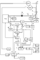
- FIG. 1 is a block diagram of a welding power source for carrying out an arc welding control method according to Embodiment 1 of the present invention. Hereinafter, each block will be described with reference to FIG.
- the power supply main circuit PM receives a commercial power supply (not shown) such as a three-phase 200V, performs output control by inverter control or the like according to a drive signal Dv described later, and outputs an output voltage E.
- a commercial power supply such as a three-phase 200V
- the power supply main circuit PM is driven by a primary rectifier that rectifies commercial power, a smoothing capacitor that smoothes the rectified direct current, and the drive signal Dv that converts the smoothed direct current to high-frequency alternating current.
- An inverter circuit a high-frequency transformer that steps down the high-frequency alternating current to a voltage value suitable for welding, and a secondary rectifier that rectifies the stepped-down high-frequency alternating current into direct current.
- the reactor WL smoothes the output voltage E described above.
- the inductance value of the reactor WL is, for example, 200 ⁇ H.
- the feed motor WM receives a feed control signal Fc, which will be described later, and feeds the welding wire 1 at a feed speed Fw by periodically repeating forward feed and reverse feed.
- a motor with fast transient response is used as the feed motor WM.
- the feeding motor WM may be installed near the tip of the welding torch 4. In some cases, two feed motors WM are used to form a push-pull feed system.
- the welding wire 1 is fed through the welding torch 4 by the rotation of the feeding roll 5 coupled to the feeding motor WM, and an arc 3 is generated between the base metal 2 and the welding wire 1.
- a welding voltage Vw is applied between the power feed tip (not shown) in the welding torch 4 and the base material 2, and a welding current Iw is conducted.
- the output voltage setting circuit ER outputs a predetermined output voltage setting signal Er.
- the output voltage detection circuit ED detects and smoothes the output voltage E and outputs an output voltage detection signal Ed.
- the voltage error amplification circuit EV receives the output voltage setting signal Er and the output voltage detection signal Ed, and amplifies an error between the output voltage setting signal Er (+) and the output voltage detection signal Ed ( ⁇ ).
- the voltage error amplification signal Ev is output.
- the hot start current setting circuit IHR outputs a predetermined hot start current setting signal Ihr.
- the current detection circuit ID detects the welding current Iw and outputs a current detection signal Id.
- the current error amplifier circuit EI receives the hot start current setting signal Giveaway and the current detection signal Id as input and amplifies an error between the hot start current setting signal Giveaway (+) and the current detection signal Id ( ⁇ ).
- the current error amplification signal Ei is output.
- the welding power source is controlled at a constant current during a period in which the hot start current is energized (hot start period).
- the current energization determination circuit CD receives the current detection signal Id as described above, and determines that the welding current Iw is energized when this value is equal to or greater than a threshold value (about 10 A), and the current energization determination becomes a high level.
- the signal Cd is output.
- the power supply characteristic switching circuit SW receives the current error amplification signal Ei, the voltage error amplification signal Ev, and the current conduction determination signal Cd as input, and from the time when the current conduction determination signal Cd changes to a high level (energization).
- the current error amplification signal Ei is output as the error amplification signal Ea during the predetermined hot start period, and the voltage error amplification signal Ev is output as the error amplification signal Ea during the other periods.
- the voltage detection circuit VD detects the welding voltage Vw and outputs a voltage detection signal Vd.
- the short circuit determination circuit SD receives the voltage detection signal Vd as described above, and when this value is less than the short circuit determination value (about 10 V), it determines that it is a short circuit period and becomes a high level, and when it is above, it is an arc period. And a short circuit determination signal Sd that is at a low level is output.
- the welding start circuit ST outputs a welding start signal St that becomes a high level when starting the welding power source.
- the welding start circuit ST corresponds to a start switch of the welding torch 4, a PLC that controls the welding process, a robot control device, and the like.
- the drive circuit DV receives the error amplification signal Ea and the welding start signal St, and performs PWM modulation control based on the error amplification signal Ea when the welding start signal St is at a high level (welding start).
- the drive signal Dv for driving the inverter circuit in the power supply main circuit PM is output.
- the transient welding period timer circuit STK receives the current energization determination signal Cd and the feed speed setting signal Fr described later, and selects one of the following 1) to 4) for processing, thereby performing transient welding.
- the period timer signal Stk is output. 1) When the current energization determination signal Cd changes to the High level (energization) and is set to the High level, and after the predetermined period has elapsed, the forward feed period or the reverse feed period of the feed speed setting signal Fr ends.
- the transient welding period timer signal Stk that is reset to the low level is output.
- the current energization determination signal Cd changes to the high level (energization), it is set to the high level, and then when the feed speed setting signal Fr ends the predetermined number of forward feed periods or the predetermined number of reverse feed periods.
- a transient welding period timer signal Stk that is reset to a low level is output.
- the current energization determination signal Cd is set to the High level when it changes to the High level (energization), and after the predetermined period has passed, the signal is set to the Low level when the normal feed period of the feed speed setting signal Fr ends.
- the transient welding period timer signal Stk to be reset is output.
- the average feed speed setting circuit FAR outputs a predetermined average feed speed setting signal Far.
- the period setting circuit TFR outputs a predetermined period setting signal Tfr.
- the amplitude setting circuit WFR outputs a predetermined amplitude setting signal Wfr.
- the steady welding period feed rate setting circuit FCR receives the average feed rate setting signal Far, the cycle setting signal Tfr and the amplitude setting signal Wfr, and receives the amplitude Wf and cycle setting signal determined by the amplitude setting signal Wfr.
- a steady welding period feed speed setting signal Fcr is output that has a waveform obtained by shifting a predetermined trapezoidal wave that changes to a positive / negative target shape at a period Tf determined by Tfr to the forward feed side by the value of the average feed speed setting signal Far. .
- the steady welding period feed speed setting signal Fcr will be described in detail with reference to FIG.
- the transient welding period feed speed setting circuit FKR receives the current energization determination signal Cd and the short circuit determination signal Sd as input, and performs the process described in detail in FIG. Outputs Fkr.
- the feed speed setting circuit FR includes the steady welding period feed speed setting signal Fcr, the transient welding period feed speed setting signal Fkr, the welding start signal St, the current conduction determination signal Cd, and the transient.
- a feed speed setting signal Fr is output.
- the welding start signal St becomes a high level (welding start)
- a feed speed setting signal Fr switched from 0 to a predetermined slow-down speed is output.
- the current conduction determination signal Cd becomes High level (energization)
- the transient welding period feed speed setting signal Fkr is output as the feed speed setting signal Fr.
- the steady welding period feed speed setting signal Fcr is output as the feed speed setting signal Fr.
- the feed control circuit FC receives the feed speed setting signal Fr and receives a feed control signal Fc for feeding the welding wire 1 at a feed speed Fw corresponding to the value of the feed speed setting signal Fr. It outputs to said feed motor WM.
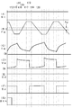
- FIG. 2 is a timing chart of each signal at the start of welding in the welding power source of FIG. 1, showing the arc welding control method according to the first embodiment of the present invention.
- A shows the time change of the welding start signal St
- B shows the time change of the feeding speed Fw
- C shows the time change of the welding current Iw
- D shows the time change of the welding voltage Vw
- E shows the time change of the current energization determination signal Cd
- Cd shows the time change of the short circuit determination signal Sd
- G Indicates the time change of the transient welding period timer signal Stk.
- the feed speed Fw is a forward feed period above 0 and a reverse feed period below.
- the forward feeding is to feed the welding wire 1 in a direction approaching the base material 2, and the reverse feeding is to feed in a direction away from the base material 2.
- the feeding speed Fw changes in a trapezoidal waveform and has a waveform shifted to the forward feeding side. For this reason, the average value of the feeding speed Fw is a positive value, and the welding wire 1 is normally fed on average.
- the transient welding period reverse feed period is a predetermined transient welding period reverse feed acceleration period, arc re-generation as shown in FIG.
- the transition welding period reverse feed peak period, the predetermined transient welding period reverse feed peak value, and the predetermined transient welding period reverse feed deceleration period are formed.
- the transient welding period forward feed period is the predetermined transient welding period forward feed. It is formed of an acceleration period, a transient welding period positive feed peak period that ends when a short circuit occurs, a predetermined transient welding period positive feed peak value, and a predetermined transient welding period forward feed deceleration period.
- the feeding speed Fw changes from 0 to a predetermined positive slowdown speed as shown in FIG.
- the welding wire 1 is fed forward. This slowdown speed is set to a small value of about 1 m / min.
- the welding voltage Vw becomes the no-load voltage value of the maximum output voltage value as shown in FIG.
- the welding voltage Vw rapidly decreases to a short-circuit voltage value of several volts as shown in FIG. Is less than a predetermined short-circuit determination value (about 10 V), so that the short-circuit determination signal Sd changes to the high level (short-circuit) as shown in FIG.
- the welding current Iw having a predetermined hot start current value (about 200 to 500 A) starts energization at time t2, as shown in FIG.
- the energization determination signal Cd changes to a high level (energization). In response to this, as shown in FIG.
- the transient welding period timer signal Stk changes to the High level, and returns to the Low level at time t12 as described later.
- the period from time t2 to t12 is the transient welding period Tk.
- the hot start current is energized during a predetermined hot start period from time t2 to t41.
- the feed speed Fw is switched from forward feed to reverse feed as shown in FIG. Then, it accelerates rapidly to a predetermined transient welding period reverse feed peak value, and enters the transient welding period reverse feed peak period.
- the delay period is set to about 1 to 10 ms. The delay period may be set to 0 so as not to be delayed. This delay is provided in order to generate an initial arc smoothly when the welding wire 1 contacts the base material 2.
- the welding voltage Vw rapidly increases to an arc voltage value of several tens of volts as shown in FIG.
- the short circuit determination signal Sd changes to a low level (arc).
- the transient welding period reverse feed deceleration period from time t4 to t5 is entered, as shown in FIG. The above-mentioned transient welding period slows down from the reverse feed peak value to zero.
- the transition welding period reverse feed deceleration period starts from time t4. Will enter.
- the welding current Iw decreases from the hot start current value to an arc current value that changes according to the arc load, as shown in FIG.
- the hot start period from time t2 to t41 is a predetermined value, it is uncertain which period the feed speed Fw is at when the hot start period ends.
- the period from time t4 to t7 is the arc period.
- the feed speed Fw enters the transient welding period forward feed peak period, as shown in FIG. .
- the welding voltage Vw rapidly decreases to a short circuit voltage value of several V as shown in FIG. 4D, and in response to this, as shown in FIG.
- the short circuit determination signal Sd changes to a high level (short circuit).
- the welding current Iw gradually increases during the short circuit period.
- the short-circuit determination signal Sd changes to a high level (short-circuit) during the transient welding period normal feed peak period, as shown in FIG. 5B, the transient welding period regular feed deceleration period from time t7 to t8 is entered.
- the transient welding period is decelerated from the positive feed peak value to zero.
- the period from time t7 to t10 is a short circuit period.
- the feed speed Fw enters the transient welding period reverse feed peak period, as shown in FIG. .
- the short circuit determination signal Sd changes to the low level (arc).
- the welding current Iw gradually decreases during the arc period.
- the period from time t11 to t12 is the second transient welding period normal feeding period, which is the same as the operation from time t5 to t8 described above, and therefore the description will not be repeated.
- the transient welding period timer signal Stk is a periodical transition period normal feed period after a predetermined period has elapsed from the time when the current energization determination signal Cd changes to the high level (energization) at time t2. Or it changes to the Low level (steady welding period) in synchronization with the timing when the transient welding period reverse feed period ends.
- the transient welding period timer signal Stk changes to the Low level at time t12 when the transient welding period normal feed period ends.
- the period from time t2 to t12 is the transient welding period Tk, and the period after time t12 is the steady welding period.
- the transient welding period Tk may be set to a time point when a predetermined number of transient welding period reverse feed periods or a predetermined number of transient welding period normal feed periods have ended since the start of energization of the welding current.
- the transient welding period Tk may be set to the time when the normal welding period of the transient welding period ends after a predetermined period has elapsed from the time when the welding current starts energization. Furthermore, the transient welding period Tk may be set to a point in time when a predetermined number of transient welding period normal feed periods have ended after the welding current has started energization. In this way, the steady welding period always starts from the steady welding period reverse feed period, and the transition to the welding state in the steady welding period becomes smoother than when the steady welding period starts from the regular feed period.
- the transient welding period Tk is set as a period until a molten pool having the same size as the steady welding period is formed.
- the transient welding period Tk is in the range of about 50 to 1000 ms.
- waveforms for two cycles are drawn during the transient welding period Tk, but actually, waveforms for 5 to 100 cycles are included.
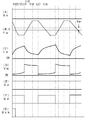
- FIG. 3 is a timing chart of each signal during the steady welding period in the welding power source of FIG. 1, showing the arc welding control method according to the first embodiment of the present invention.
- This figure shows the operation during the steady welding period after the transition welding period Tk of FIG. 2 ends at time t12.
- A shows the time change of the welding start signal St
- B shows the time change of the feeding speed Fw
- C shows the time change of the welding current Iw
- D shows the time change of the welding voltage Vw
- E shows the time change of the current energization determination signal Cd
- (F) shows the time change of the short circuit determination signal Sd
- G Indicates the time change of the transient welding period timer signal Stk.
- the operation during the steady welding period will be described with reference to FIG.
- the feed speed Fw shown in FIG. 5B is controlled to the value of the feed speed setting signal Fr output from the feed speed setting circuit FR of FIG.
- a predetermined trapezoidal wave that changes to a positive / negative target shape with the amplitude Wf determined by the amplitude setting signal Wfr and the period Tf determined by the period setting signal Tfr is positive by the value of the average feed speed setting signal Far.
- the waveform is shifted to the sending side. For this reason, as shown in FIG.
- the feed speed Fw is determined by using the average feed speed Fa indicated by a broken line determined by the average feed speed setting signal Far as a reference line, and the target amplitude Wf and It becomes a trapezoidal wave-shaped feeding speed pattern determined in advance with the period Tf. That is, the amplitude above the reference line and the amplitude below the reference line have the same value, and the period above and below the reference line have the same value.
- the steady welding period reverse feed period at times t12 to t16 is respectively a predetermined steady welding period reverse feed as shown in FIG. It consists of an acceleration period, steady welding period reverse feed peak period, steady welding period reverse feed peak value, and steady welding period reverse feed deceleration period
- the normal welding period forward feed period from time t16 to t20 is a predetermined steady welding period positive It is formed of a feed acceleration period, a steady welding period forward feed peak period, a steady welding period forward feed peak value, and a steady welding period forward feed deceleration period.
- the process proceeds to the steady welding period.
- the welding start signal St remains at the high level (welding start) as shown in FIG. 5A, and the current conduction determination signal Cd is also at the high level as shown in FIG. (Energized) remains.
- the feeding speed Fw enters the above-mentioned steady welding period reverse feed acceleration period from time t12 to t13, and accelerates from 0 to the above-mentioned steady welding period reverse feed peak value.
- the short circuit determination signal Sd is at a high level (short circuit) as shown in FIG. It has become.
- the feed speed Fw enters the above normal welding period reverse feed peak period from time t13 to t15, and the above steady welding is performed.
- Period reverse feed peak value At time t14 during this period, the arc 3 is regenerated by the pinch force generated by reverse feeding and energization of the welding current Iw.
- the welding voltage Vw rapidly increases to an arc voltage value of several tens of volts as shown in FIG. 4D, and the short-circuit determination signal Sd is set to the low level (arc) as shown in FIG. ).
- the welding current Iw gradually decreases thereafter.
- this period was terminated with the reoccurrence of the arc as a trigger. However, during the steady welding period, this period is terminated when a predetermined period elapses regardless of the reoccurrence of the arc. .
- the feeding speed Fw enters the above-mentioned steady welding period forward feed acceleration period from time t16 to t17, and accelerates from 0 to the above-mentioned steady welding period forward feed peak value. During this period, it remains in the short-circuit state.
- the feed speed Fw enters the regular welding peak forward feed period from time t17 to t19 as shown in FIG. It becomes the peak value during the period.
- a short circuit occurs due to normal feeding.
- the welding voltage Vw rapidly decreases to a short-circuit voltage value of several V as shown in FIG. 4D, and the short-circuit determination signal Sd is at a high level (short-circuit) as shown in FIG. To change.
- the welding current Iw gradually increases thereafter.
- Tk this period was terminated with the occurrence of a short circuit as a trigger. However, during the steady welding period, this period is terminated when a predetermined period elapses regardless of the occurrence of a short circuit.
- the feed speed Fw is a trapezoidal wave.
- it may be a waveform that repeats periodically such as a sine wave or a triangular wave.
- the welding wire is fed forward at the start of welding, and after the welding wire comes into contact with the base material and the welding current is energized, the forward / reverse feed control is started from the welding wire backward feeding period. . This is because the initial arc is generated more smoothly when the forward / reverse feed control is started from the reverse feed period than when the forward / reverse feed control is started from the forward feed period.
- the transition is made to the normal feed period, and when the short feed period is reached during the forward feed period, the reverse feed period Then, during the steady welding period, a predetermined forward feed period and a predetermined reverse feed period are alternately switched. If the predetermined forward feed period and the predetermined reverse feed period are alternately switched during the transient welding period in which the weld pool is not sufficiently formed as in the steady welding period, the welding state becomes unstable. During transient welding, the welding state is stabilized by shifting to the forward feed period triggered by the reoccurrence of the arc during the reverse feed period, and entering the reverse feed period triggered by the occurrence of a short circuit during the forward feed period. can do.
- the waveform parameter of the feeding speed is set to a different value during the transient welding period than during the steady welding period.
- the waveform parameter is a reverse feed acceleration period, reverse feed peak value (reverse feed amplitude), reverse feed deceleration period, forward feed acceleration period, forward feed peak value (forward feed amplitude), or forward feed deceleration period. At least one of these waveform parameters is set to a different value during the transient welding period than during the steady welding period. Thereby, the welding state during the transient welding period is stabilized. At this time, it is desirable to set the waveform parameter so that the average value of the feeding speed during the transient welding period is smaller than the average value of the feeding speed during the steady welding period.
- the amplitude is the total value of the transient welding period forward feed peak value and the transient welding period reverse feed peak value (absolute value) during the transient welding period, and the steady welding period forward feed peak value during the steady welding period. It is the sum of the steady welding period reverse feed peak value (absolute value). It is desirable to set the amplitude to a smaller value during the transient welding period than during the steady welding period. In this way, the welding state during the transient welding period is further stabilized. Furthermore, it is desirable to set the forward feed amplitude (forward feed peak value) to a smaller value during the transient welding period than during the steady welding period. In this way, the welding state during the transient welding period is further stabilized.
- the invention of the second embodiment includes a push-side feed motor that performs forward feed control in addition to the pull-side feed motor that performs forward / reverse feed control of the first embodiment, and the push-side feed motor is welded.
- the motor accelerates with a slope during a predetermined acceleration period from the time when the current starts energization.
- FIG. 4 is a block diagram of a welding power source for carrying out the arc welding control method according to the second embodiment of the present invention. This figure corresponds to FIG. 1 described above, and the same reference numerals are given to the same blocks and their description will not be repeated. This figure is obtained by adding a push-side feed motor WM2, an acceleration period setting circuit TUR, a second feed speed setting circuit FR2, and a second feed control circuit FC2 to FIG. Hereinafter, these blocks will be described with reference to FIG.
- the feeding motor WM is a pull-side feeding motor and is installed downstream of the feeding system.
- the forward / reverse feed control for the feed motor WM is the same as in the first embodiment.
- a push-side feeding motor WM2 is newly installed on the upstream side of the feeding system. This push-side feed motor WM2 is forward-feed controlled by a second feed control signal Fc2 described later.
- the acceleration period setting circuit TUR outputs a predetermined acceleration period setting signal Tur.
- the second feed speed setting circuit FR2 receives the acceleration period setting signal Tur, the average feed speed setting signal Far, the welding start signal St and the current energization determination signal Cd as input, and performs the following processing to obtain the second feed speed.
- the average feed speed setting signal has an inclination from the second slowdown speed.
- a second feed speed setting signal Fr2 that accelerates to the value of Far is output.
- the second feed speed setting signal Fr2 which is the value of the average feed speed setting signal Far is output.
- the second feed control circuit FC2 receives the second feed speed setting signal Fr2 as an input, and feeds the welding wire 1 at a feed speed corresponding to the value of the second feed speed setting signal Fr2.
- the 2-feed control signal Fc2 is output to the push-side feed motor WM2.
- FIG. 5 is a timing chart of each signal at the start of welding in the welding power source of FIG. 4, showing the arc welding control method according to the second embodiment of the present invention.
- A shows the time change of the welding start signal St
- B shows the time change of the feed speed Fw on the pull side
- C shows the time change of the welding current Iw
- D shows the time change of the welding voltage Vw
- E shows the time change of the current conduction determination signal Cd
- (F) shows the time change of the short circuit determination signal Sd.
- G shows the change over time of the transient welding period timer signal Stk
- (H) shows the change over time of the push-side feed speed Fw2. This figure corresponds to FIG.
- the push-side feed speed Fw2 is a second slow-down speed that is a positive value determined in advance from 0, as shown in FIG.
- the welding wire 1 is fed forward.
- the second slowdown speed is set to the same value as the slowdown speed of the feed speed Fw shown in FIG.
- the push-side feed speed Fw2 Accelerates with an inclination and becomes the value of the average feed speed setting signal Far at time t111 between time t11 and time t12. That is, during the predetermined acceleration period Tu from time t3 to t111, the push-side feed speed Fw2 accelerates with an inclination.
- This acceleration period Tu is set by the acceleration period setting signal Tur in FIG.
- This acceleration period Tu is set to be substantially equal to the transient welding period Tk from time t2 to time t12.
- the push-side feed speed Fw2 after time t111 is fed at a constant speed with a predetermined average feed speed setting signal Far.
- the push-side feed speed Fw2 after time t111 may be feedback-controlled so that the average value of the pull-side feed speed Fw is detected and equal to this average value.
- the push-side feed motor that performs forward feed control is provided.
- the vehicle accelerates with an inclination during a predetermined acceleration period from the start of energization.
- the invention of the third embodiment is the same as that of the first embodiment in the operation during the transient welding period shown in FIG. 2, but the operation during the steady welding period shown in FIG. 3 is different. That is, in the invention of the first embodiment, during the steady welding period, the waveform of the feeding speed has a predetermined pattern, and the forward feeding period and the backward feeding period of the feeding speed are triggered by the occurrence of arc and short circuit. Will not be switched. On the other hand, in the invention of the third embodiment, as in the transient welding period, the forward feed period and the reverse feed period of the feeding speed are switched during the steady welding period with the occurrence of arc and short circuit as a trigger. It is done.
- FIG. 6 is a block diagram of a welding power source for carrying out the arc welding control method according to the third embodiment of the present invention.
- This figure corresponds to FIG. 1 described above, and the same reference numerals are given to the same blocks, and the description thereof will not be repeated.
- the average feed speed setting circuit FAR, the cycle setting circuit TFR and the amplitude setting circuit WFR of FIG. 1 are deleted.
- a forward feed acceleration period setting circuit TSUR, a forward feed deceleration period setting circuit TSDR, a reverse feed acceleration period setting circuit TRUR, a reverse feed deceleration period setting circuit TRDR, a forward feed amplitude setting circuit WSR, and a reverse feed amplitude setting circuit WRR are added.
- the steady welding period feeding speed setting circuit FCR in FIG. 1 is replaced with a second steady welding period feeding speed setting circuit FCR2.
- the forward feed acceleration period setting circuit TSUR outputs a predetermined forward feed acceleration period setting signal Tsur.
- the forward feed deceleration period setting circuit TSDR outputs a predetermined forward feed deceleration period setting signal Tsdr.
- the reverse acceleration period setting circuit TRUR outputs a predetermined reverse acceleration period setting signal Trur.
- the reverse feed deceleration period setting circuit TRDR outputs a predetermined reverse feed deceleration period setting signal Trdr.
- the forward feed amplitude setting circuit WSR outputs a predetermined forward feed amplitude setting signal Wsr for setting the forward feed peak value.
- the reverse feed amplitude setting circuit WRR outputs a predetermined reverse feed amplitude setting signal Wrr for setting the reverse feed peak value.
- the second steady welding period feed speed setting circuit FCR2 includes the above-described forward feed acceleration period setting signal Tsur, the above-described forward feed deceleration period setting signal Tsdr, the above-described reverse feed acceleration period setting signal Trur, and the above-described reverse feed deceleration period setting.
- Tsur forward feed acceleration period setting signal
- Tsdr forward feed deceleration period setting signal
- Trur reverse feed acceleration period setting signal
- Sd the forward feed amplitude setting signal Wsr
- the short circuit determination signal Sd the feed speed pattern generated by the following processing is set as the steady welding period feed speed setting.
- the feed speed pattern generated by the following processing is set as the steady welding period feed speed setting.
- Output as signal Fcr.
- a steady welding period feed speed setting signal Fcr that linearly decelerates to 0 is output. 4) Subsequently, during the forward feed acceleration period Tsu determined by the forward feed acceleration period setting signal Tsur, the steady welding period feed that linearly accelerates from 0 to the positive feed peak value Wsp determined by the forward feed amplitude setting signal Wsr. A feed speed setting signal Fcr is output. 5) Subsequently, during the forward feed peak period Tsp, the steady welding period feed speed setting signal Fcr for maintaining the forward feed peak value Wsp is output.
- FIG. 7 is a timing chart of each signal during the steady welding period in the welding power source of FIG. 6, showing the arc welding control method according to the third embodiment of the present invention.
- This figure shows the operation during the steady welding period after the transition welding period Tk of FIG. 2 ends at time t12.
- A shows the time change of the welding start signal St
- B shows the time change of the feeding speed Fw
- C shows the time change of the welding current Iw
- D shows the time change of the welding voltage Vw
- E shows the time change of the current energization determination signal Cd
- (F) shows the time change of the short circuit determination signal Sd
- G Indicates the time change of the transient welding period timer signal Stk.
- the operation during the steady welding period will be described with reference to FIG.
- the feed speed Fw shown in FIG. 5B is controlled to the value of the feed speed setting signal Fr (steady welding period feed speed setting signal Fcr) output from the feed speed setting circuit FR of FIG.
- the feed speed Fw is a steady welding period reverse feed acceleration period Tru determined by a reverse feed acceleration period setting signal Trur in FIG. 6, a steady welding period reverse feed peak period Trp that continues until an arc is generated, and a reverse feed deceleration period in FIG.
- Normal welding period reverse feed deceleration period Trd determined by the setting signal Trdr, normal welding acceleration period forward feed period Tsu determined by the normal feed acceleration period setting signal Tsur in FIG.
- the process proceeds to the steady welding period.
- the welding start signal St remains at the high level (welding start) as shown in FIG. 5A, and the current conduction determination signal Cd is also at the high level as shown in FIG. (Energized) remains.
- the feeding speed Fw enters a predetermined steady welding period reverse acceleration period Tru at times t12 to t13, and accelerates from 0 to a predetermined steady welding period reverse feed peak value Wrp. During this period, the short circuit period continues.
- the short-circuit determination signal Sd changes to a low level (arc period) as shown in FIG.
- a transition is made to a predetermined steady welding period reverse feed deceleration period Trd between times t14 and t15, and as shown in FIG. 5B, the feed speed Fw is the above-mentioned steady welding period reverse feed peak value Wrp. Decelerate from 0 to 0.
- the welding voltage Vw rapidly increases to an arc voltage value of several tens of volts as shown in FIG. 4D, and the welding current Iw gradually decreases during the arc period as shown in FIG.
- the short circuit determination signal Sd changes to a high level (short circuit period) as shown in FIG.
- a transition is made to a predetermined steady welding period forward feed deceleration period Tsd between times t17 and t18, and as shown in FIG. 5B, the feed speed Fw is the above-mentioned steady welding period forward feed peak value Wsp. Decelerate from 0 to 0.
- the welding voltage Vw rapidly decreases to a short circuit voltage value of several V as shown in FIG. 4D, and the welding current Iw gradually increases during the short circuit period as shown in FIG.
- the arc generation is used as a trigger to switch from the steady welding period reverse feed period to the regular welding period forward feed period, and the steady welding is triggered by the occurrence of a short circuit.
- the period is switched from the normal feed period to the steady welding period reverse feed period.
- the normal welding period during the transitional welding period from the start of welding to the convergence to the steady welding period is different from that during the steady welding period.
Abstract
Description
溶接ワイヤの送給速度を正送期間と逆送期間とに交互に切り換える正逆送給制御を行って、短絡期間とアーク期間とを発生させて溶接するアーク溶接制御方法において、
溶接開始時は前記溶接ワイヤを正送し、溶接電流の通電開始後に前記溶接ワイヤの前記逆送期間から前記正逆送給制御を開始する、
ことを特徴とする。 In order to solve the above-described problem, the arc welding control method of the present invention includes:
In the arc welding control method of performing welding by generating a short circuit period and an arc period by performing forward / reverse feed control for alternately switching the feeding speed of the welding wire between the forward feed period and the reverse feed period,
The welding wire is forwardly fed at the start of welding, and the forward / reverse feed control is started from the backward feeding period of the welding wire after the start of energization of the welding current.
It is characterized by that.
ことを特徴とする。 In the arc welding control method of the present invention, during the transient welding period until convergence to the steady welding period, when the arc period is reached during the reverse feed period, the arc feed period is shifted to the forward feed period, and the short circuit is performed during the forward feed period. When it becomes a period, it shifts to the reverse sending period,
It is characterized by that.
ことを特徴とする。 In the arc welding control method of the present invention, the transient welding period is a period from the time when the welding current starts to energize to the time when the forward feed period or the reverse feed period ends after the lapse of a predetermined period.
It is characterized by that.
ことを特徴とする。 In the arc welding control method of the present invention, the transient welding period is a period from the time when the welding current starts energization to the time when a predetermined number of forward feed periods or a predetermined number of reverse feed periods ends,
It is characterized by that.
ことを特徴とする。 In the arc welding control method of the present invention, the waveform parameter of the feed speed is set to a value different from that during the steady welding period during the transient welding period.
It is characterized by that.
ことを特徴とする。 In the arc welding control method of the present invention, the average value of the feeding speed is set to a value different from that during the steady welding period during the transient welding period.
It is characterized by that.
ことを特徴とする。 In the arc welding control method of the present invention, the amplitude of the feed speed is set to a value different from that during the steady welding period during the transient welding period.
It is characterized by that.
ことを特徴とする。 In the arc welding control method of the present invention, the forward feed amplitude of the feed speed is set to a smaller value during the transient welding period than during the steady welding period.
It is characterized by that.
ことを特徴とする。 The arc welding control method of the present invention includes a push-side feed motor that performs forward feed control in addition to the pull-side feed motor that performs forward / reverse feed control, and the push-side feed motor includes the welding current. Accelerate with an inclination after energization of
It is characterized by that.
図1は、本発明の実施の形態1に係るアーク溶接制御方法を実施するための溶接電源のブロック図である。以下、同図を参照して各ブロックについて説明する。 [Embodiment 1]
FIG. 1 is a block diagram of a welding power source for carrying out an arc welding control method according to Embodiment 1 of the present invention. Hereinafter, each block will be described with reference to FIG.
1)電流通電判別信号CdがHighレベル(通電)に変化した時点でHighレベルにセットされ、それから所定期間が経過した後に、送給速度設定信号Frの正送期間又は逆送期間が終了した時点でLowレベルにリセットされる過渡溶接期間タイマ信号Stkを出力する。
2)電流通電判別信号CdがHighレベル(通電)に変化した時点でHighレベルにセットされ、それから送給速度設定信号Frが所定回数の正送期間又は所定回数の逆送期間を終了した時点でLowレベルにリセットされる過渡溶接期間タイマ信号Stkを出力する。
3)電流通電判別信号CdがHighレベル(通電)に変化した時点でHighレベルにセットされ、それから所定期間が経過した後に、送給速度設定信号Frの正送期間が終了した時点でLowレベルにリセットされる過渡溶接期間タイマ信号Stkを出力する。
4)電流通電判別信号CdがHighレベル(通電)に変化した時点でHighレベルにセットされ、それから送給速度設定信号Frが所定回数の正送期間を終了した時点でLowレベルにリセットされる過渡溶接期間タイマ信号Stkを出力する。 The transient welding period timer circuit STK receives the current energization determination signal Cd and the feed speed setting signal Fr described later, and selects one of the following 1) to 4) for processing, thereby performing transient welding. The period timer signal Stk is output.
1) When the current energization determination signal Cd changes to the High level (energization) and is set to the High level, and after the predetermined period has elapsed, the forward feed period or the reverse feed period of the feed speed setting signal Fr ends. The transient welding period timer signal Stk that is reset to the low level is output.
2) When the current energization determination signal Cd changes to the high level (energization), it is set to the high level, and then when the feed speed setting signal Fr ends the predetermined number of forward feed periods or the predetermined number of reverse feed periods. A transient welding period timer signal Stk that is reset to a low level is output.
3) The current energization determination signal Cd is set to the High level when it changes to the High level (energization), and after the predetermined period has passed, the signal is set to the Low level when the normal feed period of the feed speed setting signal Fr ends. The transient welding period timer signal Stk to be reset is output.
4) A transient that is set to High level when the current energization determination signal Cd changes to High level (energization), and then is reset to Low level when the feed speed setting signal Fr ends a predetermined number of normal feed periods. The welding period timer signal Stk is output.
1)溶接開始信号StがHighレベル(溶接開始)になると、0から予め定めたスローダウン速度に切り換えられた送給速度設定信号Frを出力する。Fr=0のときは溶接ワイヤ1の送給は停止している。
2)電流通電判別信号CdがHighレベル(通電)になると、過渡溶接期間送給速度設定信号Fkrを送給速度設定信号Frとして出力する。
3)過渡溶接期間タイマ信号StkがLowレベルになると、定常溶接期間送給速度設定信号Fcrを送給速度設定信号Frとして出力する。 The feed speed setting circuit FR includes the steady welding period feed speed setting signal Fcr, the transient welding period feed speed setting signal Fkr, the welding start signal St, the current conduction determination signal Cd, and the transient. With the welding period timer signal Stk as an input, the following processing is performed and a feed speed setting signal Fr is output.
1) When the welding start signal St becomes a high level (welding start), a feed speed setting signal Fr switched from 0 to a predetermined slow-down speed is output. When Fr = 0, feeding of the welding wire 1 is stopped.
2) When the current conduction determination signal Cd becomes High level (energization), the transient welding period feed speed setting signal Fkr is output as the feed speed setting signal Fr.
3) When the transient welding period timer signal Stk becomes Low level, the steady welding period feed speed setting signal Fcr is output as the feed speed setting signal Fr.
時刻t2に電流通電判別信号CdがHighレベルに変化してから予め定めた遅延期間が経過した時刻t3において、同図(B)に示すように、送給速度Fwは正送から逆送に切り換えられて、予め定めた過渡溶接期間逆送ピーク値まで急加速し、過渡溶接期間逆送ピーク期間に入る。上記の遅延期間は1~10ms程度に設定される。遅延期間を0にして、遅延しないようにしても良い。この遅延は、溶接ワイヤ1が母材2に接触したときに、初期アークを円滑に発生させるために設けている。 [Operation of the first transient welding period reverse feed period from time t3 to t5]
At time t3 when a predetermined delay period has elapsed since the current energization determination signal Cd changed to high level at time t2, the feed speed Fw is switched from forward feed to reverse feed as shown in FIG. Then, it accelerates rapidly to a predetermined transient welding period reverse feed peak value, and enters the transient welding period reverse feed peak period. The delay period is set to about 1 to 10 ms. The delay period may be set to 0 so as not to be delayed. This delay is provided in order to generate an initial arc smoothly when the welding wire 1 contacts the
時刻t5において過渡溶接期間逆送減速期間が終了すると、同図(B)に示すように、送給速度Fwは時刻t5~t6の上記の過渡溶接期間正送加速期間に入り、0から上記の過渡溶接期間正送ピーク値まで加速する。 [Operation of the first transient welding period normal feed period from time t5 to t8]
When the transient welding period reverse feed deceleration period ends at time t5, the feed speed Fw enters the above-described transient welding period normal feed acceleration period from time t5 to t6, as shown in FIG. Accelerate to the forward feed peak value during the transient welding period.
時刻t8において過渡溶接期間正送減速期間が終了すると、同図(B)に示すように、送給速度Fwは時刻t8~t9の上記の過渡溶接期間逆送加速期間に入り、0から上記の過渡溶接期間逆送ピーク値まで加速する。 [Operation of the second transient welding period reverse feed period from time t8 to t11]
When the forward welding deceleration period of the transient welding period ends at time t8, as shown in FIG. 5B, the feed speed Fw enters the above-mentioned transient welding period reverse acceleration period of time t8 to t9. Accelerate to reverse feed peak value during transient welding.
同図(B)に示すように、送給速度Fwは時刻t12~t13の上記の定常溶接期間逆送加速期間に入り、0から上記の定常溶接期間逆送ピーク値まで加速する。この期間中は、時刻t11~t12の過渡溶接期間正送期間中に発生した短絡状態が継続しているので、同図(F)に示すように、短絡判別信号SdはHighレベル(短絡)となっている。 [Operation of the first regular welding period reverse feed period from time t12 to t16]
As shown in FIG. 5B, the feeding speed Fw enters the above-mentioned steady welding period reverse feed acceleration period from time t12 to t13, and accelerates from 0 to the above-mentioned steady welding period reverse feed peak value. During this period, since the short circuit state that occurred during the normal welding period of the transient welding period from time t11 to t12 continues, the short circuit determination signal Sd is at a high level (short circuit) as shown in FIG. It has become.
同図(B)に示すように、送給速度Fwは時刻t16~t17の上記の定常溶接期間正送加速期間に入り、0から上記の定常溶接期間正送ピーク値まで加速する。この期間中は、短絡状態のままである。 [Operation of first normal welding period normal feed period from time t16 to t20]
As shown in FIG. 5B, the feeding speed Fw enters the above-mentioned steady welding period forward feed acceleration period from time t16 to t17, and accelerates from 0 to the above-mentioned steady welding period forward feed peak value. During this period, it remains in the short-circuit state.
(定常溶接期間中の台形波の数値例)
周期Tf=10ms、振幅Wf=60m/min、半周期の各傾斜期間=1.2ms、ピーク期間=2.6ms、ピーク値=30m/minの台形波に設定すると、この台形波を平均送給速度Fa=5m/minだけ正送側にシフトした波形となる。平均溶接電流は約250Aとなる。この場合の各波形パラメータは、以下のようになる。
定常溶接期間逆送期間=4.6ms、定常溶接期間逆送加速期間=1.0ms、定常溶接期間逆送ピーク期間=2.6ms、定常溶接期間逆送ピーク値=-25m/min、定常溶接期間逆送減速期間=1.0ms
定常溶接期間正送期間=5.4ms、定常溶接期間正送加速期間=1.4ms、定常溶接期間正送ピーク期間=2.6ms、定常溶接期間正送ピーク値=35m/min、定常溶接期間正送減速期間=1.4ms
(過渡溶接期間中の台形波の数値例)
過渡溶接期間逆送加速期間=1.0ms、過渡溶接期間逆送ピーク値=-17.5m/min、過渡溶接期間逆送減速期間=1.0ms、過渡溶接期間正送加速期間=1.4ms、過渡溶接期間正送ピーク値=24.5m/min、過渡溶接期間正送減速期間=1.4ms Numerical examples of the trapezoidal wave of the feeding speed Fw during the steady welding period and the transient welding period are shown below.
(Numerical example of trapezoidal wave during steady welding)
When a trapezoidal wave with period Tf = 10 ms, amplitude Wf = 60 m / min, each half period of inclination period = 1.2 ms, peak period = 2.6 ms, peak value = 30 m / min, this trapezoidal wave is averaged. The waveform is shifted to the forward feed side by the speed Fa = 5 m / min. The average welding current is about 250A. Each waveform parameter in this case is as follows.
Normal welding period reverse feed period = 4.6 ms, steady welding period reverse feed acceleration period = 1.0 ms, steady welding period reverse feed peak period = 2.6 ms, steady welding period reverse feed peak value = −25 m / min, steady welding Period Reverse feed deceleration period = 1.0 ms
Regular welding period forward feed period = 5.4 ms, steady welding period forward feed acceleration period = 1.4 ms, steady welding period forward feed peak period = 2.6 ms, steady welding period forward feed peak value = 35 m / min, steady welding period Normal feed deceleration period = 1.4 ms
(Numerical example of trapezoidal wave during transient welding)
Transient welding period reverse feed acceleration period = 1.0 ms, transient welding period reverse feed peak value = -17.5 m / min, transient welding period reverse feed deceleration period = 1.0 ms, transient welding period forward feed acceleration period = 1.4 ms , Transient welding period forward feed peak value = 24.5m / min, transient welding period forward feed deceleration period = 1.4ms
実施の形態2の発明は、実施の形態1の正逆送給制御を行うプル側送給モータに加えて正送送給制御を行うプッシュ側送給モータを備え、プッシュ側送給モータは溶接電流が通電を開始した時点から予め定めた加速期間中は傾斜を有して加速する。 [Embodiment 2]
The invention of the second embodiment includes a push-side feed motor that performs forward feed control in addition to the pull-side feed motor that performs forward / reverse feed control of the first embodiment, and the push-side feed motor is welded. The motor accelerates with a slope during a predetermined acceleration period from the time when the current starts energization.
1)溶接開始信号StがHighレベル(溶接開始)になると、0から予め定めた第2スローダウン速度に切り換えられた第2送給速度設定信号Fr2を出力する。Fr2=0のときは溶接ワイヤ1の送給は停止している。
2)電流通電判別信号CdがHighレベル(通電)に変化した時点から加速期間設定信号Turによって定まる加速期間Tu中は、上記の第2スローダウン速度から傾斜を有して平均送給速度設定信号Farの値まで加速する第2送給速度設定信号Fr2を出力する。
3)その後は、平均送給速度設定信号Farの値となる第2送給速度設定信号Fr2を出力する。 The acceleration period setting circuit TUR outputs a predetermined acceleration period setting signal Tur. The second feed speed setting circuit FR2 receives the acceleration period setting signal Tur, the average feed speed setting signal Far, the welding start signal St and the current energization determination signal Cd as input, and performs the following processing to obtain the second feed speed. The setting signal Fr2 is output.
1) When the welding start signal St becomes a high level (welding start), a second feed speed setting signal Fr2 switched from 0 to a predetermined second slowdown speed is output. When Fr2 = 0, feeding of the welding wire 1 is stopped.
2) During the acceleration period Tu determined by the acceleration period setting signal Tur from the time when the current energization determination signal Cd changes to the High level (energization), the average feed speed setting signal has an inclination from the second slowdown speed. A second feed speed setting signal Fr2 that accelerates to the value of Far is output.
3) After that, the second feed speed setting signal Fr2 which is the value of the average feed speed setting signal Far is output.
実施の形態3の発明は、実施の形態1において、図2の過渡溶接期間中の動作は同一であり、図3の定常溶接期間中の動作が異なるものである。すなわち、実施の形態1の発明では、定常溶接期間中は所定パターンの送給速度の波形となっており、アーク発生及び短絡発生がトリガーとなって送給速度の正送期間と逆送期間とが切り換えられることはない。これに対して、実施の形態3の発明では、過渡溶接期間中と同様に、定常溶接期間中も、アーク発生及び短絡発生をトリガーとして、送給速度の正送期間と逆送期間とが切り換えられる。 [Embodiment 3]
The invention of the third embodiment is the same as that of the first embodiment in the operation during the transient welding period shown in FIG. 2, but the operation during the steady welding period shown in FIG. 3 is different. That is, in the invention of the first embodiment, during the steady welding period, the waveform of the feeding speed has a predetermined pattern, and the forward feeding period and the backward feeding period of the feeding speed are triggered by the occurrence of arc and short circuit. Will not be switched. On the other hand, in the invention of the third embodiment, as in the transient welding period, the forward feed period and the reverse feed period of the feeding speed are switched during the steady welding period with the occurrence of arc and short circuit as a trigger. It is done.
1)逆送加速期間設定信号Trurによって定まる逆送加速期間Tru中は0から逆送振幅設定信号Wrrによって定まる負の値の逆送ピーク値Wrpまで直線状に加速する定常溶接期間送給速度設定信号Fcrを出力する。
2)続いて、逆送ピーク期間Trp中は、上記の逆送ピーク値Wrpを維持する定常溶接期間送給速度設定信号Fcrを出力する。
3)短絡判別信号SdがHighレベル(短絡期間)からLowレベル(アーク期間)に変化すると、逆送減速期間設定信号Trdrによって定まる逆送減速期間Trdに移行し、上記の逆送ピーク値Wrpから0まで直線状に減速する定常溶接期間送給速度設定信号Fcrを出力する。
4)続いて、正送加速期間設定信号Tsurによって定まる正送加速期間Tsu中は0から正送振幅設定信号Wsrによって定まる正の値の正送ピーク値Wspまで直線状に加速する定常溶接期間送給速度設定信号Fcrを出力する。
5)続いて、正送ピーク期間Tsp中は、上記の正送ピーク値Wspを維持する定常溶接期間送給速度設定信号Fcrを出力する。
6)短絡判別信号SdがLowレベル(アーク期間)からHighレベル(短絡期間)に変化すると、正送減速期間設定信号Tsdrによって定まる正送減速期間Tsdに移行し、上記の正送ピーク値Wspから0まで直線状に減速する定常溶接期間送給速度設定信号Fcrを出力する。
7)上記の1)~6)を繰り返すことによって正負の台形波状に変化する送給パターンの定常溶接期間送給速度設定信号Fcrが生成される。 The second steady welding period feed speed setting circuit FCR2 includes the above-described forward feed acceleration period setting signal Tsur, the above-described forward feed deceleration period setting signal Tsdr, the above-described reverse feed acceleration period setting signal Trur, and the above-described reverse feed deceleration period setting. With the signal Trdr, the forward feed amplitude setting signal Wsr, the reverse feed amplitude setting signal Wrr and the short circuit determination signal Sd as inputs, the feed speed pattern generated by the following processing is set as the steady welding period feed speed setting. Output as signal Fcr. When this steady welding period feed speed setting signal Fcr is 0 or more, it becomes a normal feed period, and when it is less than 0, it becomes a reverse feed period.
1) During the reverse feed acceleration period Tru determined by the reverse feed acceleration period setting signal Trur, a steady welding period feed speed setting for linear acceleration from 0 to a negative reverse feed peak value Wrp determined by the reverse feed amplitude setting signal Wrr. The signal Fcr is output.
2) Subsequently, during the reverse feed peak period Trp, the steady welding period feed speed setting signal Fcr for maintaining the reverse feed peak value Wrp is output.
3) When the short circuit determination signal Sd changes from the High level (short circuit period) to the Low level (arc period), it shifts to the reverse feed deceleration period Trd determined by the reverse feed deceleration period setting signal Trdr, and from the reverse feed peak value Wrp. A steady welding period feed speed setting signal Fcr that linearly decelerates to 0 is output.
4) Subsequently, during the forward feed acceleration period Tsu determined by the forward feed acceleration period setting signal Tsur, the steady welding period feed that linearly accelerates from 0 to the positive feed peak value Wsp determined by the forward feed amplitude setting signal Wsr. A feed speed setting signal Fcr is output.
5) Subsequently, during the forward feed peak period Tsp, the steady welding period feed speed setting signal Fcr for maintaining the forward feed peak value Wsp is output.
6) When the short circuit determination signal Sd changes from the Low level (arc period) to the High level (short circuit period), it shifts to the forward feed deceleration period Tsd determined by the forward feed deceleration period setting signal Tsdr, and from the forward feed peak value Wsp. A steady welding period feed speed setting signal Fcr that linearly decelerates to 0 is output.
7) By repeating the above 1) to 6), a steady welding period feed speed setting signal Fcr of a feed pattern that changes into a positive and negative trapezoidal waveform is generated.
同図(B)に示すように、送給速度Fwは時刻t12~t13の所定の定常溶接期間逆送加速期間Truに入り、0から所定の定常溶接期間逆送ピーク値Wrpまで加速する。この期間中は短絡期間が継続している。 [Operation in the normal welding period reverse feed period from time t12 to t15]
As shown in FIG. 5B, the feeding speed Fw enters a predetermined steady welding period reverse acceleration period Tru at times t12 to t13, and accelerates from 0 to a predetermined steady welding period reverse feed peak value Wrp. During this period, the short circuit period continues.
時刻t15において定常溶接期間逆送減速期間Trdが終了すると、時刻t15~t16の所定の定常溶接期間正送加速期間Tsuに移行する。この定常溶接期間正送加速期間Tsu中は、同図(B)に示すように、送給速度Fwは0から上記の定常溶接期間正送ピーク値Wspまで加速する。この期間中はアーク期間が継続している。 [Operations during regular welding period normal feed period from time t15 to t18]
When the steady welding period reverse feed deceleration period Trd ends at time t15, the routine proceeds to a predetermined steady welding period forward feed acceleration period Tsu at times t15 to t16. During the steady welding period forward feed acceleration period Tsu, the feed speed Fw accelerates from 0 to the steady welding period forward feed peak value Wsp as shown in FIG. During this period, the arc period continues.
本出願は、2014年9月8日出願の日本特許出願(特願2014-181993)、2014年9月29日出願の日本特許出願(特願2014-197876)に基づくものであり、その内容はここに取り込まれる。 As mentioned above, although this invention was demonstrated by specific embodiment, this invention is not limited to this embodiment, A various change is possible in the range which does not deviate from the technical idea of the disclosed invention.
This application is based on a Japanese patent application filed on September 8, 2014 (Japanese Patent Application No. 2014-181993) and a Japanese patent application filed on September 29, 2014 (Japanese Patent Application No. 2014-197876). Captured here.
2 母材
3 アーク
4 溶接トーチ
5 送給ロール
CD 電流通電判別回路
Cd 電流通電判別信号
DV 駆動回路
Dv 駆動信号
E 出力電圧
Ea 誤差増幅信号
ED 出力電圧検出回路
Ed 出力電圧検出信号
EI 電流誤差増幅回路
Ei 電流誤差増幅信号
ER 出力電圧設定回路
Er 出力電圧設定信号
EV 電圧誤差増幅回路
Ev 電圧誤差増幅信号
Fa 平均送給速度
FAR 平均送給速度設定回路
Far 平均送給速度設定信号
FC 送給制御回路
Fc 送給制御信号
FC2 第2送給制御回路
Fc2 第2送給制御信号
FCR 定常溶接期間送給速度設定回路
Fcr 定常溶接期間送給速度設定信号
FCR2 第2定常溶接期間送給速度設定回路
FKR 過渡溶接期間送給速度設定回路
Fkr 過渡溶接期間送給速度設定信号
FR 送給速度設定回路
Fr 送給速度設定信号
FR2 第2送給速度設定回路
Fr2 第2送給速度設定信号
Fw 送給速度/プル側の送給速度
Fw2 プッシュ側送給速度
ID 電流検出回路
Id 電流検出信号
IHR ホットスタート電流設定回路
Ihr ホットスタート電流設定信号
Iw 溶接電流
PM 電源主回路
SD 短絡判別回路
Sd 短絡判別信号
ST 溶接開始回路
St 溶接開始信号
STK 過渡溶接期間タイマ回路
Stk 過渡溶接期間タイマ信号
SW 電源特性切換回路
Tf 周期
TFR 周期設定回路
Tfr 周期設定信号
Tk 過渡溶接期間
Trd 定常溶接期間逆送減速期間
TRDR 逆送減速期間設定回路
Trdr 逆送減速期間設定信号
Trp 定常溶接期間逆送ピーク期間
Tru 定常溶接期間逆送加速期間
TRUR 逆送加速期間設定回路
Trur 逆送加速期間設定信号
Tsd 定常溶接期間正送減速期間
TSDR 正送減速期間設定回路
Tsdr 正送減速期間設定信号
Tsp 定常溶接期間正送ピーク期間
Tsu 定常溶接期間正送加速期間
TSUR 正送加速期間設定回路
Tsur 正送加速期間設定信号
Tu 加速期間
TUR 加速期間設定回路
Tur 加速期間設定信号
VD 電圧検出回路
Vd 電圧検出信号
Vw 溶接電圧
Wf 振幅
WFR 振幅設定回路
Wfr 振幅設定信号
WL リアクトル
WM 送給モータ
WM2 プッシュ側送給モータ
Wrp 定常溶接期間逆送ピーク値
WRR 逆送振幅設定回路
Wrr 逆送振幅設定信号
Wsp 定常溶接期間正送ピーク値
WSR 正送振幅設定回路
Wsr 正送振幅設定信号 DESCRIPTION OF SYMBOLS 1 Welding wire 2 Base material 3 Arc 4 Welding torch 5 Feed roll CD Current energization discrimination circuit Cd Current energization discrimination signal DV Drive circuit Dv Drive signal E Output voltage Ea Error amplification signal ED Output voltage detection circuit Ed Output voltage detection signal EI Current Error amplification circuit Ei Current error amplification signal ER Output voltage setting circuit Er Output voltage setting signal EV Voltage error amplification circuit Ev Voltage error amplification signal Fa Average feeding speed FAR Average feeding speed setting circuit Far Average feeding speed setting signal FC Control circuit Fc feed control signal FC2 second feed control circuit Fc2 second feed control signal FCR steady welding period feed speed setting circuit Fcr steady welding period feed speed setting signal FCR2 second steady welding period feed speed setting circuit FKR Transient welding period feed speed setting circuit Fkr Transient welding period feed speed Setting signal FR Feeding speed setting circuit Fr Feeding speed setting signal FR2 Second feeding speed setting circuit Fr2 Second feeding speed setting signal Fw Feeding speed / pull-side feeding speed Fw2 Push-side feeding speed ID Current detection Circuit Id Current detection signal IHR Hot start current setting circuit Ihr Hot start current setting signal Iw Welding current PM Power supply main circuit SD Short circuit determination circuit Sd Short circuit determination signal ST Welding start circuit St Welding start signal STK Transient welding period timer circuit Stk Transient welding period Timer signal SW Power supply characteristic switching circuit Tf Period TFR Period setting circuit Tfr Period setting signal Tk Transient welding period Trd Regular welding period Reverse feed deceleration period TRDR Reverse feed deceleration period setting circuit Trdr Reverse feed deceleration period setting signal Trp Regular welding period reverse feed peak Period Tru Regular welding period Reverse feed acceleration period TRUR Reverse Acceleration period setting circuit Trur Reverse feed acceleration period setting signal Tsd Regular welding period forward feed deceleration period TSDR Forward feed deceleration period setting circuit Tsdr Forward feed deceleration period setting signal Tsp Steady welding period forward feed peak period Tsu Su steady welding period forward feed acceleration period TSUR Positive feed acceleration period setting circuit Tsur Positive feed acceleration period setting signal Tu Acceleration period TUR Acceleration period setting circuit Tur Acceleration period setting signal VD Voltage detection circuit Vd Voltage detection signal Vw Welding voltage Wf Amplitude WFR Amplitude setting circuit Wfr Amplitude setting signal WL Reactor WM Feed motor WM2 Push-side feed motor Wrp Normal welding period reverse feed peak value WRR Reverse feed amplitude setting circuit Wrr Reverse feed amplitude setting signal Wsp Regular welding period forward feed peak value WSR Forward feed amplitude setting circuit Wsr Forward feed amplitude setting signal
Claims (9)
- 溶接ワイヤの送給速度を正送期間と逆送期間とに交互に切り換える正逆送給制御を行って、短絡期間とアーク期間とを発生させて溶接するアーク溶接制御方法において、
溶接開始時は前記溶接ワイヤを正送し、溶接電流の通電開始後に前記溶接ワイヤの前記逆送期間から前記正逆送給制御を開始する、
ことを特徴とするアーク溶接制御方法。 In the arc welding control method of performing welding by generating a short circuit period and an arc period by performing forward / reverse feed control for alternately switching the feeding speed of the welding wire between the forward feed period and the reverse feed period,
The welding wire is forwardly fed at the start of welding, and the forward / reverse feed control is started from the backward feeding period of the welding wire after the start of energization of the welding current.
An arc welding control method characterized by the above. - 定常溶接期間に収束するまでの過渡溶接期間中は、前記逆送期間中に前記アーク期間になると前記正送期間に移行し、前記正送期間中に前記短絡期間になると前記逆送期間に移行する、
ことを特徴とする請求項1に記載のアーク溶接制御方法。 During the transient welding period until convergence to the steady welding period, when the arc period is reached during the reverse feed period, the forward feed period is started, and when the short circuit period is reached during the forward feed period, the reverse feed period is started. To
The arc welding control method according to claim 1, wherein: - 前記過渡溶接期間を、前記溶接電流が通電を開始した時点から所定期間が経過した後に正送期間又は逆送期間が終了した時点までの期間とする、
ことを特徴とする請求項2に記載のアーク溶接制御方法。 The transient welding period is a period from the time when the welding current starts energization to the time when the forward feed period or the reverse feed period ends after a predetermined period has elapsed,
The arc welding control method according to claim 2, wherein: - 前記過渡溶接期間を、前記溶接電流が通電を開始した時点から所定回数の正送期間又は所定回数の逆送期間が終了した時点までの期間とする、
ことを特徴とする請求項2に記載のアーク溶接制御方法。 The transient welding period is a period from the time when the welding current starts energization to the time when the predetermined number of forward feed periods or the predetermined number of reverse feed periods ends.
The arc welding control method according to claim 2, wherein: - 前記送給速度の波形パラメータを、前記過渡溶接期間中は前記定常溶接期間中とは異なる値に設定する、
ことを特徴とする請求項2~4のいずれか1項に記載のアーク溶接制御方法。 The waveform parameter of the feeding speed is set to a value different from that during the steady welding period during the transient welding period.
The arc welding control method according to any one of claims 2 to 4, wherein: - 前記送給速度の平均値を、前記過渡溶接期間中は前記定常溶接期間中とは異なる値に設定する、
ことを特徴とする請求項2~4のいずれか1項に記載のアーク溶接制御方法。 The average value of the feeding speed is set to a value different from that during the steady welding period during the transient welding period.
The arc welding control method according to any one of claims 2 to 4, wherein: - 前記送給速度の振幅を、前記過渡溶接期間中は前記定常溶接期間中とは異なる値に設定する、
ことを特徴とする請求項2~4のいずれか1項に記載のアーク溶接制御方法。 The amplitude of the feeding speed is set to a value different from that during the steady welding period during the transient welding period.
The arc welding control method according to any one of claims 2 to 4, wherein: - 前記送給速度の正送振幅を、前記過渡溶接期間中は前記定常溶接期間中よりも小さな値に設定する、
ことを特徴とする請求項2~4のいずれか1項に記載のアーク溶接制御方法。 The forward feed amplitude of the feed speed is set to a smaller value during the transient welding period than during the steady welding period,
The arc welding control method according to any one of claims 2 to 4, wherein: - 前記正逆送給制御を行うプル側送給モータに加えて正送送給制御を行うプッシュ側送給モータを備え、前記プッシュ側送給モータは前記溶接電流の通電開始後に傾斜を有して加速する、
ことを特徴とする請求項1~4のいずれか1項に記載のアーク溶接制御方法。 In addition to the pull-side feed motor that performs the forward / reverse feed control, a push-side feed motor that performs the forward feed control is provided, and the push-side feed motor has an inclination after the start of energization of the welding current. To accelerate,
The arc welding control method according to any one of claims 1 to 4, wherein:
Priority Applications (5)
| Application Number | Priority Date | Filing Date | Title |
|---|---|---|---|
| JP2016547802A JP6618150B2 (en) | 2014-09-08 | 2015-08-20 | Arc welding control method |
| US15/508,632 US11033979B2 (en) | 2014-09-08 | 2015-08-20 | Arc welding control method |
| KR1020177000496A KR102305367B1 (en) | 2014-09-08 | 2015-08-20 | Arc welding control method |
| EP15840237.0A EP3192607B1 (en) | 2014-09-08 | 2015-08-20 | Arc welding control method |
| CN201580032101.XA CN106488823B (en) | 2014-09-08 | 2015-08-20 | Arc welding control method |
Applications Claiming Priority (4)
| Application Number | Priority Date | Filing Date | Title |
|---|---|---|---|
| JP2014-181993 | 2014-09-08 | ||
| JP2014181993 | 2014-09-08 | ||
| JP2014-197876 | 2014-09-29 | ||
| JP2014197876 | 2014-09-29 |
Publications (1)
| Publication Number | Publication Date |
|---|---|
| WO2016039113A1 true WO2016039113A1 (en) | 2016-03-17 |
Family
ID=55458869
Family Applications (1)
| Application Number | Title | Priority Date | Filing Date |
|---|---|---|---|
| PCT/JP2015/073441 WO2016039113A1 (en) | 2014-09-08 | 2015-08-20 | Arc welding control method |
Country Status (6)
| Country | Link |
|---|---|
| US (1) | US11033979B2 (en) |
| EP (1) | EP3192607B1 (en) |
| JP (1) | JP6618150B2 (en) |
| KR (1) | KR102305367B1 (en) |
| CN (1) | CN106488823B (en) |
| WO (1) | WO2016039113A1 (en) |
Cited By (2)
| Publication number | Priority date | Publication date | Assignee | Title |
|---|---|---|---|---|
| WO2018131345A1 (en) | 2017-01-16 | 2018-07-19 | 株式会社ダイヘン | Arc start control method for forward and reverse feeding arc welding |
| EP3517238A2 (en) | 2018-01-26 | 2019-07-31 | Daihen Corporation | Arc welding control method |
Families Citing this family (4)
| Publication number | Priority date | Publication date | Assignee | Title |
|---|---|---|---|---|
| JP6788550B2 (en) * | 2017-06-16 | 2020-11-25 | 株式会社神戸製鋼所 | Arc welding method and solid wire |
| JP7039413B2 (en) * | 2018-07-26 | 2022-03-22 | 株式会社ダイヘン | Arc welding control method |
| CN110340488B (en) * | 2019-06-01 | 2021-02-09 | 上海沪工焊接集团股份有限公司 | Lifting arc striking control method of inverter welding machine |
| JP7290904B2 (en) * | 2019-09-27 | 2023-06-14 | 株式会社ダイヘン | arc welding method |
Citations (3)
| Publication number | Priority date | Publication date | Assignee | Title |
|---|---|---|---|---|
| US20040074884A1 (en) * | 2002-10-17 | 2004-04-22 | Ssco Manufacturing, Inc., A California Corporation | Method and apparatus for improved lift-start welding |
| JP2008105035A (en) * | 2006-10-23 | 2008-05-08 | Daihen Corp | Method and device for controlling retraction of welding wire |
| JP2014140869A (en) * | 2013-01-24 | 2014-08-07 | Panasonic Corp | Arc-welding control method and arc-welding device |
Family Cites Families (15)
| Publication number | Priority date | Publication date | Assignee | Title |
|---|---|---|---|---|
| JPS521266B1 (en) | 1967-07-18 | 1977-01-13 | ||
| US4780594A (en) * | 1987-10-08 | 1988-10-25 | Dimetrics Inc. | Method and apparatus for improved control of supply of filler material to a welding location |
| WO2005099952A1 (en) * | 2004-04-16 | 2005-10-27 | Kabushiki Kaisha Yaskawa Denki | Arc start control method |
| US8692157B2 (en) * | 2005-09-15 | 2014-04-08 | Lincoln Global, Inc. | Welding system sequence control apparatus |
| JP5005332B2 (en) * | 2006-12-20 | 2012-08-22 | 株式会社ダイヘン | Arc start control method for consumable electrode arc welding |
| US8723080B2 (en) * | 2009-07-10 | 2014-05-13 | Panasonic Corporation | Arc welding control method and arc welding apparatus |
| US8993925B2 (en) | 2009-07-29 | 2015-03-31 | Panasonic Intellectual Property Management Co., Ltd. | Arc welding method and arc welding apparatus |
| WO2011024380A1 (en) * | 2009-08-28 | 2011-03-03 | パナソニック株式会社 | Arc welding method and arc welding device |
| JP5557249B2 (en) * | 2010-06-16 | 2014-07-23 | 株式会社ダイヘン | Feed control method for arc welding with short circuit |
| US8993926B2 (en) * | 2010-10-07 | 2015-03-31 | Panasonic Intellectual Property Management Co., Ltd. | Method for arc welding |
| JP2012081501A (en) * | 2010-10-13 | 2012-04-26 | Panasonic Corp | Arc welding control method, and arc welding equipment |
| CN107008998B (en) * | 2012-03-16 | 2020-03-17 | 松下知识产权经营株式会社 | Arc welding control method and arc welding device |
| JP2014237155A (en) * | 2013-06-07 | 2014-12-18 | 株式会社安川電機 | Arc-welding apparatus, arc-welding system, and arc-welding method |
| CN105705286B (en) | 2014-01-10 | 2018-11-23 | 株式会社达谊恒 | arc welding control method |
| KR102193084B1 (en) | 2014-01-15 | 2020-12-18 | 가부시키가이샤 다이헨 | Arc welding control method |
-
2015
- 2015-08-20 EP EP15840237.0A patent/EP3192607B1/en active Active
- 2015-08-20 KR KR1020177000496A patent/KR102305367B1/en active IP Right Grant
- 2015-08-20 JP JP2016547802A patent/JP6618150B2/en active Active
- 2015-08-20 WO PCT/JP2015/073441 patent/WO2016039113A1/en active Application Filing
- 2015-08-20 CN CN201580032101.XA patent/CN106488823B/en active Active
- 2015-08-20 US US15/508,632 patent/US11033979B2/en active Active
Patent Citations (3)
| Publication number | Priority date | Publication date | Assignee | Title |
|---|---|---|---|---|
| US20040074884A1 (en) * | 2002-10-17 | 2004-04-22 | Ssco Manufacturing, Inc., A California Corporation | Method and apparatus for improved lift-start welding |
| JP2008105035A (en) * | 2006-10-23 | 2008-05-08 | Daihen Corp | Method and device for controlling retraction of welding wire |
| JP2014140869A (en) * | 2013-01-24 | 2014-08-07 | Panasonic Corp | Arc-welding control method and arc-welding device |
Cited By (6)
| Publication number | Priority date | Publication date | Assignee | Title |
|---|---|---|---|---|
| WO2018131345A1 (en) | 2017-01-16 | 2018-07-19 | 株式会社ダイヘン | Arc start control method for forward and reverse feeding arc welding |
| US11364561B2 (en) | 2017-01-16 | 2022-06-21 | Daihen Corporation | Arc start control method for forward and reverse feed arc welding |
| EP3517238A2 (en) | 2018-01-26 | 2019-07-31 | Daihen Corporation | Arc welding control method |
| CN110076415A (en) * | 2018-01-26 | 2019-08-02 | 株式会社达谊恒 | Arc welding control method |
| EP3517238B1 (en) * | 2018-01-26 | 2021-01-06 | DAIHEN Corporation | Arc welding control method |
| US11090754B2 (en) | 2018-01-26 | 2021-08-17 | Daihen Corporation | Arc welding control method |
Also Published As
| Publication number | Publication date |
|---|---|
| CN106488823B (en) | 2019-02-05 |
| KR102305367B1 (en) | 2021-09-24 |
| EP3192607A1 (en) | 2017-07-19 |
| US20170252850A1 (en) | 2017-09-07 |
| EP3192607B1 (en) | 2020-05-27 |
| EP3192607A4 (en) | 2018-05-09 |
| JP6618150B2 (en) | 2019-12-11 |
| CN106488823A (en) | 2017-03-08 |
| JPWO2016039113A1 (en) | 2017-06-22 |
| KR20170053609A (en) | 2017-05-16 |
| US11033979B2 (en) | 2021-06-15 |
Similar Documents
| Publication | Publication Date | Title |
|---|---|---|
| JP6618150B2 (en) | Arc welding control method | |
| JP2012006020A (en) | Arc welding control method | |
| JP6895210B2 (en) | Arc welding control method | |
| JP6532140B2 (en) | Arc welding control method | |
| JP2017013088A (en) | Forward and reverse feeding arc-welding method | |
| JP7075705B2 (en) | Arc welding control method | |
| WO2016027638A1 (en) | Arc welding control method | |
| JP7017291B2 (en) | Arc start control method for forward / reverse feed arc welding | |
| KR102473580B1 (en) | Direct and inverse feeding ac arc welding method | |
| JP6618152B2 (en) | Arc welding control method | |
| JP6460821B2 (en) | Arc welding control method | |
| JP2016150350A (en) | Arc welding control method | |
| JP6347721B2 (en) | Arc welding control method | |
| KR102233253B1 (en) | Arc welding control method | |
| JP7329299B2 (en) | Arc welding control method | |
| JP6516291B2 (en) | Reverse feed arc welding method | |
| JP6593919B2 (en) | Forward / reverse feed AC arc welding method | |
| JP2020182959A (en) | Arc-welding control method |
Legal Events
| Date | Code | Title | Description |
|---|---|---|---|
| 121 | Ep: the epo has been informed by wipo that ep was designated in this application |
Ref document number: 15840237 Country of ref document: EP Kind code of ref document: A1 |
|
| ENP | Entry into the national phase |
Ref document number: 2016547802 Country of ref document: JP Kind code of ref document: A |
|
| ENP | Entry into the national phase |
Ref document number: 20177000496 Country of ref document: KR Kind code of ref document: A |
|
| WWE | Wipo information: entry into national phase |
Ref document number: 15508632 Country of ref document: US |
|
| REEP | Request for entry into the european phase |
Ref document number: 2015840237 Country of ref document: EP |
|
| WWE | Wipo information: entry into national phase |
Ref document number: 2015840237 Country of ref document: EP |
|
| NENP | Non-entry into the national phase |
Ref country code: DE |