EP3192482A1 - Device for detection of moisture for a device for monitoring access to a patient - Google Patents
Device for detection of moisture for a device for monitoring access to a patient Download PDFInfo
- Publication number
- EP3192482A1 EP3192482A1 EP17154688.0A EP17154688A EP3192482A1 EP 3192482 A1 EP3192482 A1 EP 3192482A1 EP 17154688 A EP17154688 A EP 17154688A EP 3192482 A1 EP3192482 A1 EP 3192482A1
- Authority
- EP
- European Patent Office
- Prior art keywords
- patient
- moisture
- monitoring
- cuff
- tubing
- Prior art date
- Legal status (The legal status is an assumption and is not a legal conclusion. Google has not performed a legal analysis and makes no representation as to the accuracy of the status listed.)
- Granted
Links
- 238000012544 monitoring process Methods 0.000 title claims abstract description 26
- 238000001514 detection method Methods 0.000 title claims description 6
- 239000008280 blood Substances 0.000 claims abstract description 29
- 210000004369 blood Anatomy 0.000 claims abstract description 29
- 239000007788 liquid Substances 0.000 claims abstract description 16
- 230000002792 vascular Effects 0.000 claims abstract description 12
- 239000004744 fabric Substances 0.000 claims description 17
- 239000000463 material Substances 0.000 claims description 14
- 238000012806 monitoring device Methods 0.000 claims description 14
- 239000002250 absorbent Substances 0.000 claims description 13
- 239000000853 adhesive Substances 0.000 claims description 9
- 230000001070 adhesive effect Effects 0.000 claims description 8
- 239000004020 conductor Substances 0.000 claims description 8
- 239000004753 textile Substances 0.000 claims description 8
- 239000002131 composite material Substances 0.000 claims description 3
- 239000011888 foil Substances 0.000 claims description 2
- 238000000502 dialysis Methods 0.000 abstract description 9
- 230000001154 acute effect Effects 0.000 abstract description 4
- 239000010410 layer Substances 0.000 description 13
- 239000000385 dialysis solution Substances 0.000 description 9
- 230000002745 absorbent Effects 0.000 description 8
- 238000011156 evaluation Methods 0.000 description 5
- 230000017531 blood circulation Effects 0.000 description 4
- 239000002985 plastic film Substances 0.000 description 4
- 229920006255 plastic film Polymers 0.000 description 4
- 239000012530 fluid Substances 0.000 description 3
- 238000001631 haemodialysis Methods 0.000 description 3
- 230000000322 hemodialysis Effects 0.000 description 3
- 230000015572 biosynthetic process Effects 0.000 description 2
- 230000007547 defect Effects 0.000 description 2
- 230000000007 visual effect Effects 0.000 description 2
- 241001631457 Cannula Species 0.000 description 1
- YCKRFDGAMUMZLT-UHFFFAOYSA-N Fluorine atom Chemical compound [F] YCKRFDGAMUMZLT-UHFFFAOYSA-N 0.000 description 1
- 239000002313 adhesive film Substances 0.000 description 1
- 239000012790 adhesive layer Substances 0.000 description 1
- 239000002390 adhesive tape Substances 0.000 description 1
- 239000012876 carrier material Substances 0.000 description 1
- 239000011248 coating agent Substances 0.000 description 1
- 238000000576 coating method Methods 0.000 description 1
- 150000001875 compounds Chemical class 0.000 description 1
- 230000001419 dependent effect Effects 0.000 description 1
- 238000013461 design Methods 0.000 description 1
- 229910052731 fluorine Inorganic materials 0.000 description 1
- 239000011737 fluorine Substances 0.000 description 1
- 239000007789 gas Substances 0.000 description 1
- 230000002209 hydrophobic effect Effects 0.000 description 1
- 238000003780 insertion Methods 0.000 description 1
- 230000037431 insertion Effects 0.000 description 1
- 230000007257 malfunction Effects 0.000 description 1
- 238000004519 manufacturing process Methods 0.000 description 1
- 238000005259 measurement Methods 0.000 description 1
- 239000012528 membrane Substances 0.000 description 1
- 238000000034 method Methods 0.000 description 1
- 230000003287 optical effect Effects 0.000 description 1
- 210000000056 organ Anatomy 0.000 description 1
- 238000004806 packaging method and process Methods 0.000 description 1
- 238000002360 preparation method Methods 0.000 description 1
- 230000035945 sensitivity Effects 0.000 description 1
- 239000000243 solution Substances 0.000 description 1
- 210000004243 sweat Anatomy 0.000 description 1
- 238000012549 training Methods 0.000 description 1
- 210000005166 vasculature Anatomy 0.000 description 1
- 238000009941 weaving Methods 0.000 description 1
Images


Classifications
-
- A—HUMAN NECESSITIES
- A61—MEDICAL OR VETERINARY SCIENCE; HYGIENE
- A61M—DEVICES FOR INTRODUCING MEDIA INTO, OR ONTO, THE BODY; DEVICES FOR TRANSDUCING BODY MEDIA OR FOR TAKING MEDIA FROM THE BODY; DEVICES FOR PRODUCING OR ENDING SLEEP OR STUPOR
- A61M1/00—Suction or pumping devices for medical purposes; Devices for carrying-off, for treatment of, or for carrying-over, body-liquids; Drainage systems
- A61M1/36—Other treatment of blood in a by-pass of the natural circulatory system, e.g. temperature adaptation, irradiation ; Extra-corporeal blood circuits
- A61M1/3621—Extra-corporeal blood circuits
- A61M1/3653—Interfaces between patient blood circulation and extra-corporal blood circuit
- A61M1/3656—Monitoring patency or flow at connection sites; Detecting disconnections
-
- A—HUMAN NECESSITIES
- A61—MEDICAL OR VETERINARY SCIENCE; HYGIENE
- A61F—FILTERS IMPLANTABLE INTO BLOOD VESSELS; PROSTHESES; DEVICES PROVIDING PATENCY TO, OR PREVENTING COLLAPSING OF, TUBULAR STRUCTURES OF THE BODY, e.g. STENTS; ORTHOPAEDIC, NURSING OR CONTRACEPTIVE DEVICES; FOMENTATION; TREATMENT OR PROTECTION OF EYES OR EARS; BANDAGES, DRESSINGS OR ABSORBENT PADS; FIRST-AID KITS
- A61F13/00—Bandages or dressings; Absorbent pads
- A61F13/15—Absorbent pads, e.g. sanitary towels, swabs or tampons for external or internal application to the body; Supporting or fastening means therefor; Tampon applicators
- A61F13/42—Absorbent pads, e.g. sanitary towels, swabs or tampons for external or internal application to the body; Supporting or fastening means therefor; Tampon applicators with wetness indicator or alarm
-
- A—HUMAN NECESSITIES
- A61—MEDICAL OR VETERINARY SCIENCE; HYGIENE
- A61F—FILTERS IMPLANTABLE INTO BLOOD VESSELS; PROSTHESES; DEVICES PROVIDING PATENCY TO, OR PREVENTING COLLAPSING OF, TUBULAR STRUCTURES OF THE BODY, e.g. STENTS; ORTHOPAEDIC, NURSING OR CONTRACEPTIVE DEVICES; FOMENTATION; TREATMENT OR PROTECTION OF EYES OR EARS; BANDAGES, DRESSINGS OR ABSORBENT PADS; FIRST-AID KITS
- A61F13/00—Bandages or dressings; Absorbent pads
- A61F13/15—Absorbent pads, e.g. sanitary towels, swabs or tampons for external or internal application to the body; Supporting or fastening means therefor; Tampon applicators
- A61F13/45—Absorbent pads, e.g. sanitary towels, swabs or tampons for external or internal application to the body; Supporting or fastening means therefor; Tampon applicators characterised by the shape
-
- A—HUMAN NECESSITIES
- A61—MEDICAL OR VETERINARY SCIENCE; HYGIENE
- A61M—DEVICES FOR INTRODUCING MEDIA INTO, OR ONTO, THE BODY; DEVICES FOR TRANSDUCING BODY MEDIA OR FOR TAKING MEDIA FROM THE BODY; DEVICES FOR PRODUCING OR ENDING SLEEP OR STUPOR
- A61M5/00—Devices for bringing media into the body in a subcutaneous, intra-vascular or intramuscular way; Accessories therefor, e.g. filling or cleaning devices, arm-rests
- A61M5/50—Devices for bringing media into the body in a subcutaneous, intra-vascular or intramuscular way; Accessories therefor, e.g. filling or cleaning devices, arm-rests having means for preventing re-use, or for indicating if defective, used, tampered with or unsterile
- A61M5/5086—Devices for bringing media into the body in a subcutaneous, intra-vascular or intramuscular way; Accessories therefor, e.g. filling or cleaning devices, arm-rests having means for preventing re-use, or for indicating if defective, used, tampered with or unsterile for indicating if defective, used, tampered with or unsterile
-
- G—PHYSICS
- G01—MEASURING; TESTING
- G01N—INVESTIGATING OR ANALYSING MATERIALS BY DETERMINING THEIR CHEMICAL OR PHYSICAL PROPERTIES
- G01N27/00—Investigating or analysing materials by the use of electric, electrochemical, or magnetic means
- G01N27/02—Investigating or analysing materials by the use of electric, electrochemical, or magnetic means by investigating impedance
- G01N27/04—Investigating or analysing materials by the use of electric, electrochemical, or magnetic means by investigating impedance by investigating resistance
- G01N27/048—Investigating or analysing materials by the use of electric, electrochemical, or magnetic means by investigating impedance by investigating resistance for determining moisture content of the material
-
- G—PHYSICS
- G01—MEASURING; TESTING
- G01N—INVESTIGATING OR ANALYSING MATERIALS BY DETERMINING THEIR CHEMICAL OR PHYSICAL PROPERTIES
- G01N27/00—Investigating or analysing materials by the use of electric, electrochemical, or magnetic means
- G01N27/02—Investigating or analysing materials by the use of electric, electrochemical, or magnetic means by investigating impedance
- G01N27/04—Investigating or analysing materials by the use of electric, electrochemical, or magnetic means by investigating impedance by investigating resistance
- G01N27/12—Investigating or analysing materials by the use of electric, electrochemical, or magnetic means by investigating impedance by investigating resistance of a solid body in dependence upon absorption of a fluid; of a solid body in dependence upon reaction with a fluid, for detecting components in the fluid
- G01N27/121—Investigating or analysing materials by the use of electric, electrochemical, or magnetic means by investigating impedance by investigating resistance of a solid body in dependence upon absorption of a fluid; of a solid body in dependence upon reaction with a fluid, for detecting components in the fluid for determining moisture content, e.g. humidity, of the fluid
-
- A—HUMAN NECESSITIES
- A61—MEDICAL OR VETERINARY SCIENCE; HYGIENE
- A61F—FILTERS IMPLANTABLE INTO BLOOD VESSELS; PROSTHESES; DEVICES PROVIDING PATENCY TO, OR PREVENTING COLLAPSING OF, TUBULAR STRUCTURES OF THE BODY, e.g. STENTS; ORTHOPAEDIC, NURSING OR CONTRACEPTIVE DEVICES; FOMENTATION; TREATMENT OR PROTECTION OF EYES OR EARS; BANDAGES, DRESSINGS OR ABSORBENT PADS; FIRST-AID KITS
- A61F13/00—Bandages or dressings; Absorbent pads
- A61F13/15—Absorbent pads, e.g. sanitary towels, swabs or tampons for external or internal application to the body; Supporting or fastening means therefor; Tampon applicators
- A61F13/42—Absorbent pads, e.g. sanitary towels, swabs or tampons for external or internal application to the body; Supporting or fastening means therefor; Tampon applicators with wetness indicator or alarm
- A61F2013/424—Absorbent pads, e.g. sanitary towels, swabs or tampons for external or internal application to the body; Supporting or fastening means therefor; Tampon applicators with wetness indicator or alarm having an electronic device
-
- A—HUMAN NECESSITIES
- A61—MEDICAL OR VETERINARY SCIENCE; HYGIENE
- A61M—DEVICES FOR INTRODUCING MEDIA INTO, OR ONTO, THE BODY; DEVICES FOR TRANSDUCING BODY MEDIA OR FOR TAKING MEDIA FROM THE BODY; DEVICES FOR PRODUCING OR ENDING SLEEP OR STUPOR
- A61M2205/00—General characteristics of the apparatus
- A61M2205/15—Detection of leaks
Definitions
- the invention relates to a device for detecting moisture for a device for monitoring access to a patient for a device with which a liquid is supplied to a patient via a hose and / or a liquid is discharged from the patient, in particular for monitoring the Vascular access in an extracorporeal blood treatment, especially for monitoring a central venous catheter for acute dialysis. Moreover, the invention relates to a device for monitoring access to a patient having a device for detecting moisture.
- the known extracorporeal blood treatment devices include, for example, dialysis devices and cell separators that require access to the patient's vasculature.
- blood is drawn from the patient via an arterial tubing with an arterial puncture cannula, which is returned to the patient via a venous tubing with a venous puncture cannula.
- a central venous catheter is used on the neck of the patient.
- Luer-Lock connection For connecting catheters and tubing for the preparation of a patient access is generally used in the medical field known luer connection system whose connecting parts comprise an inner and an outer cone.
- This connection system is called Luer-Lock connection, if the inner and outer cone to secure the connection is extended by a screw thread.
- Luer-Lock connections offer a very high level of safety, it has been shown in practice that the connecting parts can become detached due to improper handling, material defects or frequent use, or micro-cracks can occur in the material.
- the US 2010/0228231 therefore proposes to secure the connecting parts of a Luer-Lock connection system with an additional fixation of the connecting parts against unintentional loosening.
- the known monitoring devices generally rely on the standard safety devices present in the blood treatment devices which, in the event of improper vascular access, trigger an immediate interruption of the extracorporeal blood circulation.
- the known devices for monitoring a vascular access with a cannula which have a device for detecting moisture in order to be able to detect the escape of blood at the puncture site.
- the known devices for detecting moisture which are used in the known monitoring devices for patient access, are formed as a pad, which consists of an absorbent material in which a moisture sensor is embedded.
- Pads made of an absorbent material that are placed on the skin of the patient for example, from the WO 2006/008866 A1 . US 2005/0038325 A1 and US Pat. No. 6,445,304 B1 known.
- the known pads are characterized in that the moisture sensor is embedded in the absorbent material and the absorbent material is placed on the skin of the patient.
- the WO 99/24145 describes a device for detecting moisture, which has a closable with a lid housing in which a moisture sensor is arranged. To carry out the cannulas and tubing openings are provided in the housing.
- the disadvantage is that the housing with the moisture sensor is relatively expensive to produce in large quantities and is relatively difficult to handle in practice.
- the invention has for its object to provide a cost-effective to produce in large quantities device for detecting moisture.
- a further object of the invention is to provide a device for detecting moisture, which is easy and safe to handle and offers a high level of comfort.
- the invention is also based on the object of the invention to provide a device for monitoring access to a patient with such a device for detecting moisture.
- the device according to the invention for detecting moisture has a moisture sensor, which is designed as an electrically conductive structure.
- the moisture sensor of the device according to the invention is connected to a device for monitoring access to a patient, which may be part of the device with which a liquid is supplied to a patient via a hose line and / or a liquid is discharged from the patient.
- the device according to the invention for detecting moisture is characterized in that at least a portion of the device for detecting moisture is formed as a cuff-deformable section which can be placed around the circumference of the tubing or a connection system of the tubing.
- the cuff-shaped portion has fastening means for fixing the cuff-shaped portion in the hose line or the connection system enclosing position.
- the cuff-shaped portion allows the device for detecting moisture to be quickly and securely attached to a tubing or a connection system of the tubing. Additional fasteners are not required for this purpose. For example, it is not necessary to fix the device with an adhesive tape on the tubing, the connection system or the skin of the patient. This simplifies the handling of the device.
- the device according to the invention can easily be removed again from the tubing after the treatment, which is of particular importance when used for monitoring a central venous catheter. Even during treatment, the device can be easily detached from the tubing.
- the device according to the invention can be fastened in particular in the region of the hose line to which there is a connection system, for example a Luer connection system.
- a connection system for example a Luer connection system.
- the deformable to a sleeve section needs only to be placed around the connection system, so that the connection point can be monitored for leaks.
- the device according to the invention preferably has an outer liquid-impermeable layer facing the patient and an inner fluid-absorbent layer facing away from the patient. This ensures that exiting blood at the hose connection point directly to the moisture sensor. Furthermore, it is avoided that sweat from the skin of the patient or blood from a leakage of the blood tubing set at a location other than the venous connection or from a wound or other moisture from the outside reaches the humidity sensor, so that false alarms are avoided.
- the device of the invention also allows the detection of a slow blood loss, for example, as a result of handling or material defects of the hose connection.
- the connecting means of the sleeve deformable portion on at least one elongated portion and at least one slot for pulling the elongated portion To attach the device, the elongated portion only needs to be pulled through the slot.
- the cuff can be tightened tightly, so that the cuff tightly encloses the hose connection point.
- the elongated portion preferably has one or more barbs. If a plurality of barbs are provided, the elongated portion may be fixed in different positions so that the sleeve-shaped portion of the device can be adapted to hose lines or connection systems of different dimensions.
- the barbs may also be formed as a continuous series of sawteeth.
- the fastening means have a surface provided with an adhesive or adhesion layer.
- the adhesive or adhesion surface is a strip provided on the sleeve deformable portion.
- the adhesive or adhesion layer can also be designed, for example, as a hook-and-loop fastener.
- the fastening means can in principle be any means with which the corresponding sections on the one hand easily connect to each other and on the other hand can be easily solved from each other.
- the attachment of the respective sections can also be done by the formation of loops or tabs, hooks or eyes, buttons and holes or the like.
- a zipper may be provided to connect the sections.
- the elongated portion which is pulled through the slot a composite of a textile material and a film.
- the stiffness of the tab can be increased.
- an increased safety against slipping of the device according to the invention is achieved when the device for fixing the sleeve-shaped portion has a plurality of elongated portions.
- two tabs may be provided which enclose the connecting parts or the hose line on both sides of the connection system.
- connection contacts For electrical contacting of the moisture sensor, the device according to the invention has connection contacts.
- the number of connection contacts depends on the design of the humidity sensor.
- the moisture sensor may comprise two terminal contacts, between which the electrical resistance is measured.
- two more connection contacts can be provided.
- a connection tab with connection contacts it is also possible to lead out an electrical connection line from the device according to the invention, which is connected to the monitoring device.
- connection contacts are formed at the end of an elongated portion which adjoins the portion formed as a sleeve. This ensures that the connection contacts are spatially separated from the humidity sensor. Therefore, unlike the area where the humidity sensor is located, the area of electrical contact need not be sterile. This is particularly advantageous in the monitoring of central venous catheters.
- connection contacts are arranged at the end of the elongated portion, which serves as a tab for closing the cuff-shaped section is used. This can eliminate an additional tab for making electrical contact with the moisture sensor.
- the device according to the invention preferably has an outer moisture-impermeable layer facing the patient and an inner fluid-absorbent layer facing away from the patient.
- the electrically conductive structure of the moisture sensor is preferably embedded in the liquid-absorbent layer or applied to the absorbent layer.
- the electrically conductive structure does not need to extend over the entire surface of the absorbent layer, because due to the absorbency of the layer, the detection of liquid in a portion of the surface is sufficient.
- the absorbent layer for embedding the electrically conductive structure is a textile material.
- the textile material is a fabric having non-conductive warp yarns and non-conductive weft yarns, and conductive warp yarns and conductive weft yarns arranged such that the electrically conductive structure is formed in the fabric.
- Such a fabric with an electrically conductive structure is in the WO 2011/116943 described in detail.
- the electrically conductive structure may include one or more tracks extending in multiple sections over at least a portion of the sleeve portion.
- the deformable to a sleeve section may be formed differently in its dimensions and shapes.
- the cuff deformable portion is a rectangular portion that takes the form of a cylindrical portion that encloses the tubing or the connection system.
- the cuff deformable portion is a circular portion cut out over part of the circumference is.
- the portion surrounding the tubing takes the form of a funnel.
- the section cut out over part of its circumference has a central, preferably circular, cutout in the center.
- the device according to the invention can be produced in large quantities in a weaving process without great manufacturing outlay. It can also be cut out and sterilized without great technical effort and provided sterile as a disposable sensor in a suitable packaging.
- the inventive device for monitoring access to a patient in particular for monitoring the vascular access in an extracorporeal blood treatment, in particular for monitoring a central venous catheter, has the device according to the invention for detecting moisture, which is connected to the monitoring device.
- the monitoring device may trigger an audible and / or visual and / or tactile alarm when moisture is detected.
- a control signal may be generated for intervention in the control of the device by which a tubing is supplied with fluid to the patient and / or fluid is removed from the patient.
- the device according to the invention for monitoring a patient access may form a separate unit or be part of the device with which a liquid is supplied to the patient and / or liquid is removed from the patient, in particular be part of the extracorporeal blood treatment device. If the monitoring device according to the invention is part of the blood treatment device, the monitoring device can make use of specific components or components that are present in the blood treatment device anyway.
- Fig. 1 shows the essential components of a blood treatment device, in particular hemodialysis device A for acute dialysis, which has a device B for monitoring a vascular access, in particular a vascular access to a central venous catheter.
- the monitoring device B is part of the hemodialysis device A.
- the hemodialysis apparatus A has a dialyzer 1, which is subdivided by a semipermeable membrane 2 into a blood chamber 3 and a dialysis fluid chamber 4.
- the vascular access to the patient is carried out with a central venous catheter 5, which is connected to the neck of the patient.
- the central venous catheter 5 is part of the extracorporeal blood circulation I, which is only hinted at, which includes the blood chamber 3 of the dialyzer 1 and comprises tubing 6, 7.
- a blood pump 8 is provided to convey the blood in the extracorporeal circuit.
- the dialysis fluid circuit II of the dialysis machine A comprises a dialysis fluid source 10, to which a dialysis fluid supply line 11 is connected, which leads to the inlet of the dialysis fluid chamber 4 of the dialyzer 1. From the outlet of the dialysis fluid chamber 4 of the dialyzer 1, a dialysis fluid discharge line 12 departs, which leads to an outlet 13. In the dialysis fluid removal 12 a dialysis fluid pump 14 is connected.
- the control of the dialysis device takes over a central control unit 15 which controls the blood and Dialysiersammlungspumpe 8, 14 via control lines 16, 17.
- the central control unit 15 is connected via a data line 18 to an alarm unit 19, which gives an optical and / or acoustic and / or tactile alarm in the event of a malfunction.
- the monitoring device B shown only schematically serves in the present embodiment for monitoring a Luer-lock connection 9 with the connecting parts 9A and 9B for connecting the central venous catheter 5 to a tubing 9C of the extracorporeal blood circulation I.
- the monitoring device B has a device 20 for detecting moisture, which is arranged at the hose connection point 21. This device 20 is in Fig. 1 shown only schematically.
- the monitoring device B has an evaluation device 22, which is electrically connected via a connecting line 23 to the device 20 for detecting moisture.
- the connection line 23 is connected to the device 20 with an electrical connection piece 23A.
- the evaluation device 22 is connected to the central control unit 15 of the dialysis machine A.
- the evaluation device 22 of the monitoring device B In the event that blood exits the hose connection point 21 and moisturizes the device 20 for detecting moisture, the evaluation device 22 of the monitoring device B generates a control signal which the central control unit 15 receives via the data line 24, which undertakes an intervention in the blood treatment.
- the control unit 15 stops the blood pump 8 and generates an alarm signal, so that the alarm unit 19 gives an audible and / or visual and / or tactile alarm.
- the Fig. 2 shows a first embodiment of the device according to the invention for detecting moisture.
- the device has a textile carrier material 30, which in the embodiment is a fabric.
- the fabric has a section 30A with a rectangular blank which can be placed around the circumference of a tubing or connection system for connecting a catheter to a tubing.
- an elongated portion 30B connects centrally between the two narrow sides, which forms a connection tab for a connector, not shown, for connecting the device according to the invention to the evaluation device 22 of the device B for monitoring the vascular access.
- the absorbent fabric 30 has an outer side 31A facing the skin of the patient and an inner side 31B facing away from the patient's skin.
- the fabric 30 is preferably connected over its entire surface to a plastic film 32, which is impermeable to liquid and electrically non-conductive.
- the plastic film 32 gives the fabric 30 in particular in the region of the elongated Portion 30B requires the required strength and / or rigidity.
- a one-sided hydrophobic coating of the fabric may be provided.
- a hydrophobization of a PES (Polyster) fabric can be carried out, for example, by using fluorine-containing gases in a low-pressure plasma.
- the device for detecting moisture has an in Fig. 1 only schematically illustrated moisture sensor 34, which consists of an electrically conductive structure which is embedded in the tissue 30 ( Fig. 2 ).
- the fabric 30 consists of nonconductive warp threads and nonconductive weft threads as well as conductive warp threads and conductive weft threads, which are arranged in such a way that the electrically conductive structure results, which consists of a plurality of interconnect sections 35, which are only shown in an orthogonal manner. 36 composed.
- the individual conductor track sections 35, 36 extend over portions of the cuff-shaped rectangular portion 30A and lead to the end of the elongated portion 30B for connection of the connector, not shown, wherein the conductor track portions form two electrodes.
- the conductor track portions are formed as terminal contacts 33.
- the external connection contacts 33A serve for the connection for the resistance measurement of the moisture sensor, while the internal connection contacts 33B serve for the connection of a terminating resistor.
- the cuff-deformable portion 30A has a strip-shaped adhesive layer 37, which is shown in FIG Fig. 1 characterized by a hatched area.
- the adhesive or adhesion layer 37 may also be provided on both narrow sides of the portion 30A. It may be provided on the inside or outside of the portion 30A.
- section 30A will wrap around the circumference of the connection system or tubing and allow the overlapping sections to bond together when sleeve section 30A closely encloses the connection system or tubing.
- the adhesive or adhesion layer 37 may, for example, be a self-adhesive Be foil or a Velcro fastener.
- the plastic film applied to the outside of the fabric may be formed in the edge region as an adhesive film.
- the device for detecting moisture can be easily removed again from the hose line or the connection system, so that the connection system is accessible again.
- the moisture sensing device When the moisture sensing device is applied to the tubing or connection system, leakage causes the tissue 30 to become wetted with moisture, such as blood, which causes the tissue to soak up the fluid. As a result, the electrical resistance between the outer terminal contacts 33A of the electrically conductive structure changes.
- the sensor is sensitive wherever conductive threads of the first electrode can be short-circuited by moisture with conductive threads of the second electrode.
- Fig. 3 shows a second embodiment of the device 20 according to the invention prior to application to the hose or its connection system, that is, when the device does not yet form the shape of a cuff.
- This embodiment differs from the first embodiment only in that the elongate portion 30B adjoins the rectangular portion 30A not laterally but laterally. The corresponding parts are therefore provided with the same reference numerals.
- Fig. 3 clearly shows the mutually orthogonal conductor track sections 35, 36. The extending over portions of the cuff-shaped rectangular portion 30A extending trace portions 35, 36 lead up to the end of the elongated portion 30B for connection of the connector, not shown.
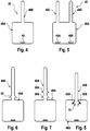
- FIGS. 4 to 10 show alternative embodiments of the device for detecting moisture, which differs from those with reference to the FIGS. 2 and 3 described embodiments differ substantially by the formation of the fastening means.
- FIGS. 4 to 8 only the outlines are shown.
- the electrically conductive structure, which is located on the inside of the fabric is not shown, since the embodiments of the FIGS. 4 to 8 from the embodiments of FIGS. 2 and 3 essentially differ only by the fastener and the different shape.
- the sleeve deformable portion 48A is a substantially rectangular portion.
- an elongate section 48B adjoins the rectangular section 48A in the center, which again forms a connection tab for the connection piece, not shown, for connecting the device for detecting moisture to the evaluation device of the monitoring device.
- the rectangular portion 48A has a slot 49 whose width is slightly larger than the width of the elongated portion 48B.
- Fig. 5 shows an alternative embodiment that differs from the embodiment of Fig. 4 only differs in that instead of a central elongated portion on one side of the rectangular portion 48 A, two eccentrically arranged elongated portions 48 C and 48 D are provided. The corresponding parts are again provided with the same reference numerals.
- the rectangular portion 48A has two off-center slots 49A and 49B through which the elongate portions 48C, 48D are pulled to tighten the collar.
- Fig. 6 to 8 show alternative embodiments that differ from the embodiment of Fig. 4 only differ by the particular shape of the elongated portion 48B. While in the embodiment of the Fig. 4 the elongate portion needs to be fixed with additional fixing means, the elongated portion 48B of FIG Fig. 6 via a barb 50 which prevents the elongate portion 48B from being pulled out of the slot 49 again.
- Fig. 7 shows an embodiment with two spaced apart barbs 50A and 50B. But it can also be provided more barbs to contract the cuff to the desired diameter can.
- Fig. 8 shows a further embodiment, which differs from the embodiments described above only in that the barb 51 is integrated into the rectangular portion 48A.
- the elongated portion 48B adjoining the rectangular portion 48A forms a cutout of the rectangular portion in the region where the elongated portion 48B is connected to the rectangular portion 48A, the outer contour being on the longitudinal sides of the elongated portion 48B cuts 52A, 52B in the rectangular portion 48A.
- the elongated portion 48B can be folded out of the rectangular portion 48A so that the barb 52 is exposed. In this way, a plurality of barbs may be formed.
- Fig. 9 Fig. 12 shows an embodiment in which the cuff-moldable portion 53 is a circular portion cut out over a part of the circumference.
- the circular portion 53 is cut out over a circumference of 90 degrees.
- the cut-out circular portion 53 has a central circular cut-out 54, the diameter of which is larger than the diameter of the tubing or connection system.
- an elongated portion 55 which forms again the connection tab for the electrical connector.
- On the other half of the section 53 are two spaced-apart slots 56A and 56B through which the elongate section 55 can be pulled.
- the elongated portion 55 can be fixed by being pulled through both slits from above and below, respectively.
- the cut-out circular section 53 is placed around the tubing or connection system with the tubing or connection system coming to rest in the central cutout 54. Subsequently, the cut-out circular portion 53 is formed into a sleeve in the form of a funnel enclosing the tubing or the connection system. The fixing then takes place with the connection tab 55.
- the conductor track sections 35, 36 of the electrically conductive structure 34, which forms the moisture sensor, is in Fig. 9 shown.
- Fig. 10 shows an alternative embodiment, which differs from the embodiment of the Fig. 9 only differs by the arrangement of the conductor track portions 35, 36 of the electrically conductive structure 34.
- the electrically conductive structure 34 in addition to the conductor track portions 35, 36 still have additional trace portions 35 A, 36 A, so that the moisture sensor of Fig. 10 a higher sensitivity than the sensor of Fig. 9 having.
Landscapes
- Health & Medical Sciences (AREA)
- Life Sciences & Earth Sciences (AREA)
- General Health & Medical Sciences (AREA)
- Vascular Medicine (AREA)
- Heart & Thoracic Surgery (AREA)
- Chemical & Material Sciences (AREA)
- Engineering & Computer Science (AREA)
- Veterinary Medicine (AREA)
- Public Health (AREA)
- Animal Behavior & Ethology (AREA)
- Biomedical Technology (AREA)
- Analytical Chemistry (AREA)
- Epidemiology (AREA)
- Pathology (AREA)
- Immunology (AREA)
- General Physics & Mathematics (AREA)
- Biochemistry (AREA)
- Physics & Mathematics (AREA)
- Electrochemistry (AREA)
- Chemical Kinetics & Catalysis (AREA)
- Anesthesiology (AREA)
- Hematology (AREA)
- Cardiology (AREA)
- External Artificial Organs (AREA)
Abstract
Die Erfindung betrifft eine Vorrichtung 20 zur Erkennung von Feuchtigkeit für eine Vorrichtung B zur Überwachung eines Zugangs zu einem Patienten für eine Einrichtung A, mit der über eine Schlauchleitung eine Flüssigkeit einem Patienten zugeführt und/oder eine Flüssigkeit von dem Patienten abgeführt wird, insbesondere zur Überwachung des Gefäßzugangs bei einer extrakorporalen Blutbehandlung, insbesondere zur Überwachung eines zentralvenösen Katheters 5 für die akute Dialyse. Die erfindungsgemäße Vorrichtung zur Erkennung von Feuchtigkeit zeichnet sich dadurch aus, dass zumindest ein Abschnitt der Vorrichtung 20 zur Erkennung von Feuchtigkeit als ein zu einer Manschette verformbarer Abschnitt 30A ausgebildet ist, der um den Umfang der Schlauchleitung oder eines Verbindungssystems der Schlauchleitung gelegt werden kann. Der manschettenförmige Abschnitt 30A weist Befestigungsmittel 37, 48 zur Fixierung des manschettenförmigen Abschnitts in der die Schlauchleitung oder das Verbindungssystem umschließenden Stellung auf. Der in der Art einer Manschette ausgebildete Abschnitt erlaubt es, die Vorrichtung zur Erkennung von Feuchtigkeit an einer Schlauchleitung oder einem Verbindungssystem der Leitung schnell und sicher zu befestigen.The invention relates to a device 20 for detecting moisture for a device B for monitoring access to a patient for a device A, with which a liquid is supplied to a patient via a hose and / or a liquid is discharged from the patient, in particular for monitoring vascular access in an extracorporeal blood treatment, in particular for monitoring a central venous catheter 5 for acute dialysis. The moisture detecting device of the present invention is characterized in that at least a portion of the moisture detecting device 20 is formed as a cuff-deformable portion 30A that can be placed around the circumference of the tubing or a connection system of the tubing. The sleeve-shaped section 30A has fastening means 37, 48 for fixing the sleeve-shaped section in the position surrounding the hose line or the connection system. The cuff-shaped portion allows the device for detecting moisture to be quickly and securely attached to a tubing or a connection system of the tubing.
Description
Die Erfindung bezieht sich auf eine Vorrichtung zur Erkennung von Feuchtigkeit für eine Vorrichtung zur Überwachung eines Zugangs zu einem Patienten für eine Einrichtung, mit der über eine Schlauchleitung eine Flüssigkeit einem Patienten zugeführt und/oder eine Flüssigkeit von dem Patienten abgeführt wird, insbesondere zur Überwachung des Gefäßzugangs bei einer extrakorporalen Blutbehandlung, insbesondere zur Überwachung eines zentralvenösen Katheters für die akute Dialyse. Darüber hinaus betrifft die Erfindung eine Vorrichtung zur Überwachung eines Zugangs zu einem Patienten, die über eine Vorrichtung zur Erkennung von Feuchtigkeit verfügt.The invention relates to a device for detecting moisture for a device for monitoring access to a patient for a device with which a liquid is supplied to a patient via a hose and / or a liquid is discharged from the patient, in particular for monitoring the Vascular access in an extracorporeal blood treatment, especially for monitoring a central venous catheter for acute dialysis. Moreover, the invention relates to a device for monitoring access to a patient having a device for detecting moisture.
Auf dem Gebiet der Medizintechnik sind verschiedene Einrichtungen bekannt, mit denen über eine Schlauchleitung Patienten Flüssigkeiten entnommen oder Flüssigkeiten den Patienten zugeführt werden können. Dabei erfolgt der Zugang zu den Patienten im Allgemeinen mit einem Katheter zum Einführen in Körperorgane oder einer Kanüle zum Punktieren von Gefäßen. Während der Untersuchung oder Behandlung ist ein ordnungsgemäßer Zugang zu dem Patienten sicher zu stellen. Daher ist es erforderlich, den Patientenzugang zu überwachen.Various devices are known in the field of medical technology with which liquids can be taken from a hose line or liquids can be supplied to the patient. The access to the patients generally takes place with a catheter for insertion into body organs or a cannula for puncturing vessels. During the examination or treatment, proper access to the patient must be ensured. Therefore, it is necessary to monitor patient access.
Einen ordnungsgemäßen Zugang zu dem Patienten setzen insbesondere auch die extrakorporalen Blutbehandlungsvorrichtungen voraus, die über einen extrakorporalen Blutkreislauf verfügen. Zu den bekannten extrakorporalen Blutbehandlungsvorrichtungen zählen beispielsweise Dialysevorrichtungen und Zellseparatoren, die einen Zugang zu dem Gefäßsystem des Patienten erforderlich machen. Bei der extrakorporalen Blutbehandlung wird dem Patienten über eine arterielle Schlauchleitung mit einer arteriellen Punktionskanüle Blut entnommen, das dem Patienten über eine venöse Schlauchleitung mit einer venösen Punktionskanüle wieder zugeführt wird. Beispielsweise bei der akuten Dialyse auf Intensivstationen wird hingegen ein zentralvenöser Katheter am Hals des Patienten eingesetzt.Proper access to the patient also requires in particular the extracorporeal blood treatment devices which have an extracorporeal blood circulation. The known extracorporeal blood treatment devices include, for example, dialysis devices and cell separators that require access to the patient's vasculature. During extracorporeal blood treatment, blood is drawn from the patient via an arterial tubing with an arterial puncture cannula, which is returned to the patient via a venous tubing with a venous puncture cannula. For example, in acute dialysis in intensive care units, a central venous catheter is used on the neck of the patient.
Zum Anschluss von Kathetern und Schlauchleitungen für die Herstellung eines Patientenzugangs findet im Allgemeinen das im medizinischen Bereich bekannte Luer-Verbindungssystem Verwendung, dessen Verbindungsteile einen Innen- und einen Außenkonus umfassen. Dieses Verbindungssystem wird als Luer-Lock-Verbindung bezeichnet, wenn der Innen- und Außenkonus zur Sicherung der Verbindung um ein Schraubgewinde erweitert ist. Obwohl die Luer-Lock-Verbindungen eine sehr hohe Sicherheit bieten, hat sich in der Praxis gezeigt, dass sich die Verbindungsteile bei unsachgemäßer Handhabung, bei Materialfehlern oder zu häufigem Gebrauch lösen oder Mikrorisse im Material auftreten können. Die
Zur Überwachung des Gefäßzugangs sind verschiedene Vorrichtungen unterschiedlicher Ausbildung bekannt. Die bekannten Überwachungsvorrichtungen greifen im Allgemeinen auf die standardmäßig in den Blutbehandlungsvorrichtungen vorhandenen Sicherheitsvorrichtungen zurück, die bei einem nicht ordnungsgemäßen Gefäßzugang eine sofortige Unterbrechung des extrakorporalen Blutkreislaufs auslösen.For monitoring the vascular access various devices of different training are known. The known monitoring devices generally rely on the standard safety devices present in the blood treatment devices which, in the event of improper vascular access, trigger an immediate interruption of the extracorporeal blood circulation.
Es sind Vorrichtungen zur Überwachung eines Gefäßzugangs mit einer Kanüle bekannt, die über eine Vorrichtung zur Erkennung von Feuchtigkeit verfügen, um an der Punktionsstelle das Austreten von Blut erkennen zu können. Die bekannten Vorrichtungen zur Erkennung von Feuchtigkeit, die bei den bekannten Überwachungsvorrichtungen für den Patientenzugang Verwendung finden, sind als Pad ausgebildet, das aus einem saugfähigen Material besteht, in das ein Feuchtigkeitssensor eingebettet ist.There are known devices for monitoring a vascular access with a cannula, which have a device for detecting moisture in order to be able to detect the escape of blood at the puncture site. The known devices for detecting moisture, which are used in the known monitoring devices for patient access, are formed as a pad, which consists of an absorbent material in which a moisture sensor is embedded.
Pads aus einem saugfähigen Material, die auf die Haut des Patienten aufgelegt werden, sind beispielsweise aus der
Die
Der Erfindung liegt die Aufgabe zugrunde, eine in großen Stückzahlen kostengünstig herzustellende Vorrichtung zur Erkennung von Feuchtigkeit zu schaffen. Eine weitere Aufgabe der Erfindung ist, eine Vorrichtung zur Erkennung von Feuchtigkeit zu schaffen, die einfach und sicher zu handhaben ist und einen hohen Tragekomfort bietet. Der Erfindung liegt auch die Aufgabe der Erfindung zugrunde, eine Vorrichtung zur Überwachung eines Zugangs zu einem Patienten mit einer derartigen Vorrichtung zur Erkennung von Feuchtigkeit bereitzustellen.The invention has for its object to provide a cost-effective to produce in large quantities device for detecting moisture. A further object of the invention is to provide a device for detecting moisture, which is easy and safe to handle and offers a high level of comfort. The invention is also based on the object of the invention to provide a device for monitoring access to a patient with such a device for detecting moisture.
Die Lösung dieser Aufgaben erfolgt erfindungsgemäß mit den Merkmalen der unabhängigen Ansprüche. Die Gegenstände der abhängigen Ansprüche betreffen vorteilhafte Ausführungsformen der Erfindung.The solution of these objects is achieved according to the invention with the features of the independent claims. The subject matters of the dependent claims relate to advantageous embodiments of the invention.
Die erfindungsgemäße Vorrichtung zur Erkennung von Feuchtigkeit weist einen Feuchtigkeitssensor auf, der als eine elektrisch leitende Struktur ausgebildet ist. Der Feuchtigkeitssensor der erfindungsgemäßen Vorrichtung wird an eine Vorrichtung zur Überwachung eines Zugangs zu einem Patienten angeschlossen, die Bestandteil der Einrichtung sein kann, mit der über eine Schlauchleitung eine Flüssigkeit einem Patienten zugeführt und/oder eine Flüssigkeit von dem Patienten abgeführt wird.The device according to the invention for detecting moisture has a moisture sensor, which is designed as an electrically conductive structure. The moisture sensor of the device according to the invention is connected to a device for monitoring access to a patient, which may be part of the device with which a liquid is supplied to a patient via a hose line and / or a liquid is discharged from the patient.
Die erfindungsgemäße Vorrichtung zur Erkennung von Feuchtigkeit zeichnet sich dadurch aus, dass zumindest ein Abschnitt der Vorrichtung zur Erkennung von Feuchtigkeit als ein zu einer Manschette verformbarer Abschnitt ausgebildet ist, der um den Umfang der Schlauchleitung oder eines Verbindungssystems der Schlauchleitung gelegt werden kann. Der manschettenförmige Abschnitt weist Befestigungsmittel zur Fixierung des manschettenförmigen Abschnitts in der die Schlauchleitung oder das Verbindungssystem umschließenden Stellung auf.The device according to the invention for detecting moisture is characterized in that at least a portion of the device for detecting moisture is formed as a cuff-deformable section which can be placed around the circumference of the tubing or a connection system of the tubing. The cuff-shaped portion has fastening means for fixing the cuff-shaped portion in the hose line or the connection system enclosing position.
Der in der Art einer Manschette ausgebildete Abschnitt erlaubt es, die Vorrichtung zur Erkennung von Feuchtigkeit an einer Schlauchleitung oder einem Verbindungssystem der Leitung schnell und sicher zu befestigen. Zusätzliche Befestigungsmittel sind hierzu nicht erforderlich. Beispielsweise ist es nicht erforderlich, die Vorrichtung mit einem Klebeband an der Schlauchleitung, dem Verbindungssystem oder der Haut des Patienten zu fixieren. Dadurch wird die Handhabung der Vorrichtung vereinfacht.The cuff-shaped portion allows the device for detecting moisture to be quickly and securely attached to a tubing or a connection system of the tubing. Additional fasteners are not required for this purpose. For example, it is not necessary to fix the device with an adhesive tape on the tubing, the connection system or the skin of the patient. This simplifies the handling of the device.
Darüber hinaus ist es von Vorteil, dass sich die erfindungsgemäße Vorrichtung nach der Behandlung wieder leicht von der Schlauchleitung abnehmen lässt, was insbesondere bei der Verwendung zur Überwachung eines zentralvenösen Katheters von Bedeutung ist. Auch während der Behandlung kann die Vorrichtung leicht von der Schlauchleitung gelöst werden.Moreover, it is advantageous that the device according to the invention can easily be removed again from the tubing after the treatment, which is of particular importance when used for monitoring a central venous catheter. Even during treatment, the device can be easily detached from the tubing.
Die erfindungsgemäße Vorrichtung kann insbesondere in dem Bereich der Schlauchleitung befestigt werden, an dem sich ein Verbindungssystem, beispielsweise ein Luer-Verbindungssystem befindet. Hierzu braucht der zu einer Manschette verformbare Abschnitt nur um das Verbindungssystem gelegt zu werden, so dass sich die Verbindungsstelle auf Leckagen überwachen lässt.The device according to the invention can be fastened in particular in the region of the hose line to which there is a connection system, for example a Luer connection system. For this purpose, the deformable to a sleeve section needs only to be placed around the connection system, so that the connection point can be monitored for leaks.
Die erfindungsgemäße Vorrichtung weist vorzugsweise eine dem Patienten zugewandte außenliegende für Flüssigkeit nicht durchlässige Schicht und eine dem Patienten abgewandte innenliegende für Flüssigkeit saugfähige Schicht auf. Dadurch wird erreicht, dass an der Schlauchverbindungsstelle austretendes Blut unmittelbar an den Feuchtigkeitssensor gelangt. Weiterhin wird vermieden, dass Schweiß von der Haut des Patienten oder Blut von einer Undichtigkeit des Blutschlauchsatzes an einer anderen Stelle als dem venösen Anschluss oder von einer Wunde oder sonstige Feuchtigkeit von außen zu dem Feuchtigkeitssensor gelangt, so dass Fehlalarme vermieden werden.The device according to the invention preferably has an outer liquid-impermeable layer facing the patient and an inner fluid-absorbent layer facing away from the patient. This ensures that exiting blood at the hose connection point directly to the moisture sensor. Furthermore, it is avoided that sweat from the skin of the patient or blood from a leakage of the blood tubing set at a location other than the venous connection or from a wound or other moisture from the outside reaches the humidity sensor, so that false alarms are avoided.
Während eine zusätzliche Sicherung einer Luer-Verbindung, die in der
Bei einer bevorzugten Ausführungsform weisen die Verbindungsmittel des zu einer Manschette verformbaren Abschnitts mindestens einen langgestreckten Abschnitt und mindestens einem Schlitz zum Durchziehen des langgestreckten Abschnitts auf. Zur Befestigung der Vorrichtung braucht der langgestreckte Abschnitt nur durch den Schlitz gezogen zu werden. Dabei kann die Manschette fest zugezogen werden, so dass die Manschette die Schlauchverbindungsstelle eng umschließt.In a preferred embodiment, the connecting means of the sleeve deformable portion on at least one elongated portion and at least one slot for pulling the elongated portion. To attach the device, the elongated portion only needs to be pulled through the slot. The cuff can be tightened tightly, so that the cuff tightly encloses the hose connection point.
Zur Fixierung des langgestreckten Abschnitts in dem Schlitz weist der langgestreckte Abschnitt vorzugsweise einen oder mehrere Widerhaken auf. Wenn mehrere Widerhaken vorgesehen sind, kann der langgestreckte Abschnitt in unterschiedlichen Positionen fixiert werden, so dass sich der manschettenförmige Abschnitt der Vorrichtung an Schlauchleitungen oder Verbindungssysteme mit unterschiedlichen Abmessungen anpassen lässt. Die Widerhaken können auch als eine kontinuierliche Reihe von Sägezähnen ausgebildet sein.For fixing the elongate portion in the slot, the elongated portion preferably has one or more barbs. If a plurality of barbs are provided, the elongated portion may be fixed in different positions so that the sleeve-shaped portion of the device can be adapted to hose lines or connection systems of different dimensions. The barbs may also be formed as a continuous series of sawteeth.
Bei einer alternativen Ausführungsform weisen die Befestigungsmittel eine mit einer Klebe- oder Adhäsionsschicht versehene Fläche auf. Vorzugsweise ist die Klebe- oder Adhäsionsfläche ein Streifen, der an dem zu einer Manschette verformbaren Abschnitt vorgesehen ist. Die Klebe- oder Adhäsionsschicht kann beispielsweise auch als Klettverschluss ausgebildet sein.In an alternative embodiment, the fastening means have a surface provided with an adhesive or adhesion layer. Preferably, the adhesive or adhesion surface is a strip provided on the sleeve deformable portion. The adhesive or adhesion layer can also be designed, for example, as a hook-and-loop fastener.
Die Befestigungsmittel können grundsätzlich sämtliche Mittel sein, mit denen sich die entsprechenden Abschnitte einerseits leicht miteinander verbinden und andererseits leicht voneinander lösen lassen. Beispielsweise kann die Befestigung der entsprechenden Abschnitte auch durch die Bildung von Schlaufen oder Laschen, Haken oder Ösen, Knöpfen und Löchern oder dergleichen erfolgen. Zur Verbindung der Abschnitte kann beispielsweise auch ein Reißverschluss vorgesehen sein.The fastening means can in principle be any means with which the corresponding sections on the one hand easily connect to each other and on the other hand can be easily solved from each other. For example, the attachment of the respective sections can also be done by the formation of loops or tabs, hooks or eyes, buttons and holes or the like. To connect the sections, for example, a zipper may be provided.
Bei einer weiteren besonders bevorzugten Ausführungsform ist insbesondere der langgestreckte Abschnitt, der durch den Schlitz gezogen wird, ein Verbund aus einem textilen Material und einer Folie. Mit diesem Materialverbund kann die Steifigkeit der Lasche erhöht werden.In a further particularly preferred embodiment, in particular, the elongated portion which is pulled through the slot, a composite of a textile material and a film. With this composite material, the stiffness of the tab can be increased.
Eine erhöhte Sicherheit gegen Abrutschen der erfindungsgemäßen Vorrichtung wird dann erzielt, wenn die Vorrichtung zur Fixierung des manschettenförmigen Abschnitts über mehrere langgestreckte Abschnitte verfügt. Beispielsweise können zwei Laschen vorgesehen sein, die auf beiden Seiten des Verbindungssystems die Verbindungsteile oder die Schlauchleitung umschließen.An increased safety against slipping of the device according to the invention is achieved when the device for fixing the sleeve-shaped portion has a plurality of elongated portions. For example, two tabs may be provided which enclose the connecting parts or the hose line on both sides of the connection system.
Zur elektrischen Kontaktierung des Feuchtigkeitssensors weist die erfindungsgemäße Vorrichtung Anschlusskontakte auf. Die Anzahl der Anschlusskontakte richtet sich nach der Ausbildung des Feuchtigkeitssensors. Beispielsweise kann der Feuchtigkeitssensor zwei Anschlusskontakte umfassen, zwischen denen der elektrische Widerstand gemessen wird. Für den Anschluss eines Abschlusswiderstandes können noch zwei weitere Anschlusskontakte vorgesehen sein. Anstelle einer Anschlusslasche mit Anschlusskontakten ist es aber auch möglich, eine elektrische Verbindungsleitung aus der erfindungsgemäßen Vorrichtung herauszuführen, die an die Überwachungsvorrichtung angeschlossen wird.For electrical contacting of the moisture sensor, the device according to the invention has connection contacts. The number of connection contacts depends on the design of the humidity sensor. For example, the moisture sensor may comprise two terminal contacts, between which the electrical resistance is measured. For the connection of a terminating resistor two more connection contacts can be provided. Instead of a connection tab with connection contacts, it is also possible to lead out an electrical connection line from the device according to the invention, which is connected to the monitoring device.
Eine bevorzugte Ausführungsform sieht vor, dass die Anschlusskontakte am Ende eines langgestreckten Abschnitts ausgebildet sind, der sich an den als Manschette ausgebildeten Abschnitt anschließt. Dadurch wird erreicht, dass die Anschlusskontakte räumlich von dem Feuchtigkeitssensor getrennt sind. Daher braucht der Bereich der elektrischen Kontaktierung im Gegensatz zu dem Bereich, an dem sich der Feuchtigkeitssensor befindet, nicht steril zu sein. Dies ist insbesondere bei der Überwachung von zentralvenösen Kathetern von Vorteil.A preferred embodiment provides that the connection contacts are formed at the end of an elongated portion which adjoins the portion formed as a sleeve. This ensures that the connection contacts are spatially separated from the humidity sensor. Therefore, unlike the area where the humidity sensor is located, the area of electrical contact need not be sterile. This is particularly advantageous in the monitoring of central venous catheters.
Bei einer besonders bevorzugten Ausführungsform sind die Anschlusskontakte am Ende des langgestreckten Abschnitts angeordnet, der als Lasche zum Zuziehen des manschettenförmigen Abschnitts dient. Damit kann eine zusätzliche Lasche zur elektrischen Kontaktierung des Feuchtigkeitssensors entfallen.In a particularly preferred embodiment, the connection contacts are arranged at the end of the elongated portion, which serves as a tab for closing the cuff-shaped section is used. This can eliminate an additional tab for making electrical contact with the moisture sensor.
Die erfindungsgemäße Vorrichtung weist vorzugsweise eine dem Patienten zugewandte außenliegende für Feuchtigkeit nicht durchlässige Schicht und eine dem Patienten abgewandte innenliegende für Flüssigkeit saugfähige Schicht auf. Die elektrisch leitende Struktur des Feuchtigkeitssensors ist vorzugsweise in die für Flüssigkeit saugfähige Schicht eingebettet oder auf die saugfähige Schicht aufgebracht. Die elektrisch leitende Struktur braucht sich nicht über die gesamte Fläche der saugfähigen Schicht erstrecken, da auf Grund der Saugfähigkeit der Schicht die Erkennung von Flüssigkeit in einem Teilbereich der Fläche ausreichend ist.The device according to the invention preferably has an outer moisture-impermeable layer facing the patient and an inner fluid-absorbent layer facing away from the patient. The electrically conductive structure of the moisture sensor is preferably embedded in the liquid-absorbent layer or applied to the absorbent layer. The electrically conductive structure does not need to extend over the entire surface of the absorbent layer, because due to the absorbency of the layer, the detection of liquid in a portion of the surface is sufficient.
Bei einer besonders bevorzugten Ausführungsform ist die saugfähige Schicht zur Einbettung der elektrisch leitfähigen Struktur ein textiles Material. Vorzugsweise ist das textile Material ein Gewebe mit nicht-leitfähigen Kettfäden und nicht-leitfähigen Schussfäden sowie leitfähigen Kettfäden und leitfähigen Schussfäden, die derart angeordnet sind, dass die elektrisch leitende Struktur in dem Gewebe ausgebildet ist. Ein derartiges Gewebe mit einer elektrisch leitfähigen Struktur ist in der
Die elektrisch leitende Struktur kann eine oder mehrere Leiterbahnen aufweisen, die sich in mehreren Abschnitten zumindest über einen Teilbereich des manschettenförmigen Abschnitts erstreckt.The electrically conductive structure may include one or more tracks extending in multiple sections over at least a portion of the sleeve portion.
Der zu einer Manschette verformbare Abschnitt kann in seinen Abmessungen und Formen unterschiedlich ausgebildet sein. Bei einer bevorzugten Ausführungsform ist der zu einer Manschette verformbare Abschnitt ein rechteckförmiger Abschnitt, der die Form eines zylindrischen Abschnitts annimmt, der die Schlauchleitung oder das Verbindungssystem umschließt.The deformable to a sleeve section may be formed differently in its dimensions and shapes. In a preferred embodiment, the cuff deformable portion is a rectangular portion that takes the form of a cylindrical portion that encloses the tubing or the connection system.
Eine alternative Ausführungsform sieht vor, dass der als Manschette verformbare Abschnitt ein kreisförmiger Abschnitt ist, der über einen Teil des Umfangs ausgeschnitten ist. Bei dieser Ausführungsform nimmt der die Schlauchleitung umschließende Abschnitt die Form eines Trichters an. Zur Durchführung der Schlauchleitung weist der über einen Teil seines Umfangs ausgeschnittene Abschnitt im Zentrum einen zentralen, vorzugsweise kreisförmigen Ausschnitt auf.An alternative embodiment provides that the cuff deformable portion is a circular portion cut out over part of the circumference is. In this embodiment, the portion surrounding the tubing takes the form of a funnel. To carry out the hose line, the section cut out over part of its circumference has a central, preferably circular, cutout in the center.
Die erfindungsgemäße Vorrichtung kann in einem Webprozess ohne großen fertigungstechnischen Aufwand in großen Stückzahlen hergestellt werden. Sie kann weiterhin ohne großen technischen Aufwand ausgeschnitten und sterilisiert und als Einwegsensor in einer geeigneten Verpackung steril bereitgestellt werden.The device according to the invention can be produced in large quantities in a weaving process without great manufacturing outlay. It can also be cut out and sterilized without great technical effort and provided sterile as a disposable sensor in a suitable packaging.
Die erfindungsgemäße Vorrichtung zur Überwachung eines Zugangs zu einem Patienten, insbesondere zur Überwachung des Gefäßzugangs bei einer extrakorporalen Blutbehandlung, insbesondere zur Überwachung eines zentralvenösen Katheters, verfügt über die erfindungsgemäße Vorrichtung zur Detektion von Feuchtigkeit, die an die Überwachungsvorrichtung angeschlossen wird. Die Überwachungsvorrichtung kann einen akustischen und/oder optischen und/oder taktilen Alarm auslösen, wenn Feuchtigkeit detektiert wird. Auch kann ein Steuersignal für einen Eingriff in die Steuerung der Einrichtung erzeugt werden, mit der eine Schlauchleitung eine Flüssigkeit dem Patienten zugeführt und/oder eine Flüssigkeit von dem Patienten abgeführt wird.The inventive device for monitoring access to a patient, in particular for monitoring the vascular access in an extracorporeal blood treatment, in particular for monitoring a central venous catheter, has the device according to the invention for detecting moisture, which is connected to the monitoring device. The monitoring device may trigger an audible and / or visual and / or tactile alarm when moisture is detected. Also, a control signal may be generated for intervention in the control of the device by which a tubing is supplied with fluid to the patient and / or fluid is removed from the patient.
Die erfindungsgemäße Vorrichtung zur Überwachung eines Patientenzugangs kann eine separate Einheit bilden oder Bestandteil der Einrichtung sein, mit der dem Patienten eine Flüssigkeit zugeführt und/oder von dem Patienten Flüssigkeit abgeführt wird, insbesondere Bestandteil der extrakorporalen Blutbehandlungsvorrichtung sein. Wenn die erfindungsgemäße Überwachungsvorrichtung Bestandteil der Blutbehandlungsvorrichtung ist, kann die Überwachungsvorrichtung von bestimmten Baugruppen oder Bauteilen Gebrauch machen, die in der Blutbehandlungsvorrichtung ohnehin vorhanden sind.The device according to the invention for monitoring a patient access may form a separate unit or be part of the device with which a liquid is supplied to the patient and / or liquid is removed from the patient, in particular be part of the extracorporeal blood treatment device. If the monitoring device according to the invention is part of the blood treatment device, the monitoring device can make use of specific components or components that are present in the blood treatment device anyway.
Im Folgenden wird ein Ausführungsbeispiel der Erfindung unter Bezugnahme auf die Zeichnungen näher erläutert.In the following an embodiment of the invention will be explained in more detail with reference to the drawings.
Es zeigen:
- Fig. 1
- die wesentlichen Komponenten einer Blutbehandlungsvorrichtung, die über eine Vorrichtung zur Überwachung eines Gefäßzugangs verfügt,
- Fig. 2
- eine vereinfachte Darstellung eines ersten Ausführungsbeispiels der erfindungsgemäßen Vorrichtung zur Erkennung von Feuchtigkeit, die an ein Verbindungssystem zum Verbinden eines zentralvenösen Katheters mit einer Schlauchleitung angelegt wird,
- Fig. 3
- ein zweites Ausführungsbeispiel der Vorrichtung von
Fig. 2 vor dem Anlegen an das Verbindungssystem, - Fig. 4
- ein drittes Ausführungsbeispiel der erfindungsgemäßen Vorrichtung in vereinfachter Darstellung,
- Fig. 5
- ein viertes Ausführungsbeispiel der Vorrichtung in vereinfachter Darstellung,
- Fig. 6
- ein fünftes Ausführungsbeispiel der Vorrichtung in vereinfachter Darstellung,
- Fig. 7
- ein sechstes Ausführungsbeispiel der Vorrichtung in vereinfachter Darstellung,
- Fig. 8
- ein siebtes Ausführungsbeispiel der Vorrichtung in vereinfachter Darstellung,
- Fig. 9
- ein achtes Ausführungsbeispiel der Vorrichtung in vereinfachter Darstellung und
- Fig. 10
- ein neuntes Ausführungsbeispiel der Vorrichtung in vereinfachter Darstellung.
- Fig. 1
- the essential components of a blood treatment device having a device for monitoring vascular access,
- Fig. 2
- a simplified representation of a first embodiment of the inventive device for detecting moisture, which is applied to a connection system for connecting a central venous catheter with a hose,
- Fig. 3
- A second embodiment of the device of
Fig. 2 before connecting to the connection system, - Fig. 4
- A third embodiment of the device according to the invention in a simplified representation,
- Fig. 5
- A fourth embodiment of the device in a simplified representation,
- Fig. 6
- A fifth embodiment of the device in a simplified representation,
- Fig. 7
- A sixth embodiment of the device in a simplified representation,
- Fig. 8
- A seventh embodiment of the device in a simplified representation,
- Fig. 9
- an eighth embodiment of the device in a simplified representation and
- Fig. 10
- a ninth embodiment of the device in a simplified representation.
Die Hämodialysevorrichtung A weist einen Dialysator 1 auf, der durch eine semipermeable Membran 2 in eine Blutkammer 3 und eine Dialysierflüssigkeitskammer 4 unterteilt ist. Der Gefäßzugang zum Patienten erfolgt mit einem zentralvenösen Katheter 5, der am Hals des Patienten angeschlossen wird. Der zentralvenöse Katheter 5 ist Teil des nur andeutungsweise dargestellten extrakorporalen Blutkreislaufs I, der die Blutkammer 3 des Dialysators 1 einschließt und Schlauchleitungen 6, 7 umfasst. Zum Fördern des Bluts im extrakorporalen Kreislauf ist eine Blutpumpe 8 vorgesehen.The hemodialysis apparatus A has a dialyzer 1, which is subdivided by a
Der Dialysierflüssigkeitskreislauf II der Dialysevorrichtung A umfasst eine Dialyseflüssigkeitsquelle 10, an der eine Dialysierflüssigkeitszuführleitung 11 angeschlossen ist, die zu dem Einlass der Dialysierflüssigkeitskammer 4 des Dialysators 1 führt. Von dem Auslass der Dialysierflüssigkeitskammer 4 des Dialysators 1 geht eine Dialysierflüssigkeitsabführleitung 12 ab, die zu einem Auslass 13 führt. In die Dialysierflüssigkeitsabführleitung 12 ist eine Dialysierflüssigkeitspumpe 14 geschaltet.The dialysis fluid circuit II of the dialysis machine A comprises a
Die Steuerung der Dialysevorrichtung übernimmt eine zentrale Steuereinheit 15, die über Steuerleitungen 16, 17 die Blut- und Dialysierflüssigkeitspumpe 8, 14 ansteuert. Die zentrale Steuereinheit 15 ist über eine Datenleitung 18 mit einer Alarmeinheit 19 verbunden, die bei einem Störfall einen optischen und/oder akustischen und/oder taktilen Alarm gibt.The control of the dialysis device takes over a
Die nur schematisch dargestellte Überwachungsvorrichtung B dient bei dem vorliegenden Ausführungsbeispiel zur Überwachung einer Luer-Lock-Verbindung 9 mit den Verbindungsteilen 9A und 9B zum Anschluss des zentralvenösen Katheters 5 an eine Schlauchleitung 9C des extrakorporalen Blutkreislaufs I. Die Überwachungsvorrichtung B verfügt über eine Vorrichtung 20 zur Erkennung von Feuchtigkeit, die an der Schlauchverbindungsstelle 21 angeordnet wird. Diese Vorrichtung 20 ist in
Über eine Datenleitung 24 ist die Auswerteinrichtung 22 mit der zentralen Steuereinheit 15 der Dialysevorrichtung A verbunden. Für den Fall, dass Blut aus der Schlauchverbindungsstelle 21 austritt und die Vorrichtung 20 zur Erkennung von Feuchtigkeit befeuchtet, erzeugt die Auswerteinrichtung 22 der Überwachungsvorrichtung B ein Steuersignal, das die zentrale Steuereinheit 15 über die Datenleitung 24 empfängt, die einen Eingriff in die Blutbehandlung vornimmt. Die Steuereinheit 15 stoppt die Blutpumpe 8 und erzeugt ein Alarmsignal, sodass die Alarmeinheit 19 einen akustischen und/oder optischen und/oder taktilen Alarm gibt.Via a
Die
Das saugfähige Gewebe 30 weist eine der Haut des Patienten zugewandte Außenseite 31A und eine der Haut des Patienten abgewandte Innenseite 31B auf. An der Außenseite 31A ist das Gewebe 30 vorzugsweise vollflächig mit einer Kunststofffolie 32 verbunden, die für Flüssigkeit nicht durchlässig und elektrisch nicht leitend ist. Darüber hinaus verleiht die Kunststofffolie 32 dem Gewebe 30 insbesondere im Bereich des langgestreckten Abschnitts 30B zum Anschluss des Anschlussstücks die erforderliche Festigkeit und/oder Steifigkeit. Als Alternative zur Verwendung einer Kunststofffolie kann eine einseitige hydrophobe Beschichtung des Gewebes vorgesehen werden. Eine Hydrophobisierung eines PES (Polyster)-Gewebes kann beispielsweise durch Einsatz von fluorhaltigen Gasen in einem Niederdruckplasma erfolgen.The
Die Vorrichtung zur Erkennung von Feuchtigkeit weist einen in
An einer Schmalseite weist der zu einer Manschette verformbare Abschnitt 30A eine streifenförmige Klebe- oder Adhäsionsschicht 37 auf, die in
Durch Lösen der Klebe- oder Adhäsionsverbindung kann die Vorrichtung zur Erkennung von Feuchtigkeit wieder leicht von der Schlauchleitung oder dem Verbindungssystem abgenommen werden, so dass das Verbindungssystem wieder zugänglich ist.By loosening the adhesive or adhesion connection, the device for detecting moisture can be easily removed again from the hose line or the connection system, so that the connection system is accessible again.
Wenn die Vorrichtung zur Erkennung von Feuchtigkeit an die Schlauchleitung oder das Verbindungssystem angelegt ist, führt eine Leckage dazu, dass das Gewebe 30 mit Feuchtigkeit, beispielsweise Blut, benetzt wird, wodurch sich das Gewebe mit der Flüssigkeit vollsaugt. Dadurch verändert sich der elektrische Widerstand zwischen den äußeren Anschlusskontakten 33A der elektrischen leitenden Struktur. Der Sensor ist überall dort sensitiv, wo leitfähige Fäden der ersten Elektrode durch Feuchtigkeit mit leitfähigen Fäden der zweiten Elektrode kurzgeschlossen werden können.When the moisture sensing device is applied to the tubing or connection system, leakage causes the
Die Figuren
Bei den Ausführungsbeispielen der
Bei dem Ausführungsbeispiel von
Die
Claims (15)
wobei die Vorrichtung zur Erkennung von Feuchtigkeit einen Feuchtigkeitssensor (34) aufweist, der als eine elektrisch leitende Struktur ausgebildet ist,
dadurch gekennzeichnet, dass zumindest ein Abschnitt der Vorrichtung zur Erkennung von Feuchtigkeit als ein zu einer Manschette verformbarer Abschnitt (30A) ausgebildet ist, der um den Umfang einer Schlauchleitung oder eines Verbindungsystems einer Schlauchleitung gelegt werden kann, wobei die Vorrichtung zur Erkennung von Feuchtigkeit Befestigungsmittel (37, 48, 55) zur Fixierung des manschettenförmigen Abschnitts (30A) in der die Schlauchleitung oder das Verbindungssystem umschließenden Stellung aufweist.A device for detecting moisture for a device for monitoring access to a patient for a device with which a liquid is supplied to a patient via a hose line and / or a liquid is removed from the patient, in particular for monitoring the vessel access in an extracorporeal blood treatment,
wherein the moisture detection device comprises a humidity sensor (34) formed as an electrically conductive structure,
characterized in that at least a portion of the moisture detection device is formed as a cuff-deformable portion (30A) that can be wrapped around the circumference of a tubing or connection system of a tubing, the moisture-detection device (10) 37, 48, 55) for fixing the sleeve-shaped portion (30A) in which the hose line or the connection system enclosing position.
Applications Claiming Priority (4)
| Application Number | Priority Date | Filing Date | Title |
|---|---|---|---|
| US201261669186P | 2012-07-09 | 2012-07-09 | |
| DE201210013474 DE102012013474A1 (en) | 2012-07-09 | 2012-07-09 | Device for detecting moisture for a device for monitoring access to a patient |
| PCT/EP2013/001842 WO2014008980A1 (en) | 2012-07-09 | 2013-06-21 | Device for detecting moisture for a device for monitoring an access to a patient |
| EP13732358.0A EP2874587B1 (en) | 2012-07-09 | 2013-06-21 | Apparatus to detect moisture for an apparatus to monitor patient access |
Related Parent Applications (1)
| Application Number | Title | Priority Date | Filing Date |
|---|---|---|---|
| EP13732358.0A Division EP2874587B1 (en) | 2012-07-09 | 2013-06-21 | Apparatus to detect moisture for an apparatus to monitor patient access |
Publications (2)
| Publication Number | Publication Date |
|---|---|
| EP3192482A1 true EP3192482A1 (en) | 2017-07-19 |
| EP3192482B1 EP3192482B1 (en) | 2019-12-18 |
Family
ID=49780518
Family Applications (2)
| Application Number | Title | Priority Date | Filing Date |
|---|---|---|---|
| EP13732358.0A Not-in-force EP2874587B1 (en) | 2012-07-09 | 2013-06-21 | Apparatus to detect moisture for an apparatus to monitor patient access |
| EP17154688.0A Active EP3192482B1 (en) | 2012-07-09 | 2013-06-21 | Device for detection of moisture for a device for monitoring access to a patient |
Family Applications Before (1)
| Application Number | Title | Priority Date | Filing Date |
|---|---|---|---|
| EP13732358.0A Not-in-force EP2874587B1 (en) | 2012-07-09 | 2013-06-21 | Apparatus to detect moisture for an apparatus to monitor patient access |
Country Status (4)
| Country | Link |
|---|---|
| US (2) | US9731086B2 (en) |
| EP (2) | EP2874587B1 (en) |
| DE (1) | DE102012013474A1 (en) |
| WO (1) | WO2014008980A1 (en) |
Cited By (1)
| Publication number | Priority date | Publication date | Assignee | Title |
|---|---|---|---|---|
| EP4372370A1 (en) * | 2022-11-18 | 2024-05-22 | Gottlieb Binder GmbH & Co. KG | Sensor device |
Families Citing this family (9)
| Publication number | Priority date | Publication date | Assignee | Title |
|---|---|---|---|---|
| DE102013012365B4 (en) | 2013-07-25 | 2019-06-13 | Fresenius Medical Care Deutschland Gmbh | Sterile tube cover for a medical tubing system |
| DE102014001898B4 (en) * | 2014-02-14 | 2021-09-09 | Fresenius Medical Care Deutschland Gmbh | Covering device and device for monitoring the connectors of a hose system |
| WO2016187337A1 (en) * | 2015-05-20 | 2016-11-24 | Loma Linda University Medical Center | Voiding cystourethrogram radiation reducing device |
| US10195367B2 (en) | 2015-10-19 | 2019-02-05 | Fresenius Medical Care Holdings, Inc. | Medical wetness sensing devices and related systems and methods |
| EP3512580B1 (en) * | 2016-09-16 | 2023-06-07 | Redsense Medical AB | A device for monitoring hose connectors and body fluid leakage |
| US10324203B2 (en) * | 2016-12-14 | 2019-06-18 | Pgs Geophysical As | Cross-line source separation based on cross-line streamer separation |
| US10441705B2 (en) | 2017-04-05 | 2019-10-15 | Fresenius Medical Care Holdings, Inc. | Medical wetness sensing devices and related systems and methods |
| JP6933937B2 (en) * | 2017-09-13 | 2021-09-08 | 日本メクトロン株式会社 | Moisture sensitive sheet and moisture sensitive system |
| US11281878B2 (en) | 2018-02-20 | 2022-03-22 | Fresenius Medical Care Holdings, Inc. | Wetness detection with biometric sensor device for use in blood treatment |
Citations (8)
| Publication number | Priority date | Publication date | Assignee | Title |
|---|---|---|---|---|
| WO1999024145A1 (en) | 1997-11-07 | 1999-05-20 | Aksys, Ltd. | Blood line separation warning device for extracorporeal circuits |
| US6445304B1 (en) | 2000-08-11 | 2002-09-03 | John J. Bandeian, Jr. | Medical alarm system |
| US20050038325A1 (en) | 2003-08-13 | 2005-02-17 | Bradley Jon Moll, Rodney L. Moll And Anne E. Moll Family Trust | Method and device for monitoring loss of body fluid and dislodgment of medical instrument from body |
| WO2006008866A1 (en) | 2004-07-16 | 2006-01-26 | Kabushiki Kaisha Awajitec | Moisture sensor |
| WO2008021462A2 (en) * | 2006-08-18 | 2008-02-21 | Fresenius Medical Care Holdings, Inc. | Wetness sensor |
| WO2009075592A2 (en) * | 2007-12-12 | 2009-06-18 | Whalley, Robin | Device and apparatus for detecting bodily fluids |
| US20100228231A1 (en) | 2006-12-05 | 2010-09-09 | Nxstage Medical, Inc. | Fluid line connector safety device |
| WO2011116943A1 (en) | 2010-03-23 | 2011-09-29 | Fresenius Medical Care Deutschland Gmbh | Moisture detection device for use with a device for monitoring an access to a patient |
Family Cites Families (24)
| Publication number | Priority date | Publication date | Assignee | Title |
|---|---|---|---|---|
| US4733383A (en) * | 1986-09-16 | 1988-03-22 | Waterbury Nelson J | Combined digital and analog timepiece and radiation monitor assembly |
| BE1004301A3 (en) | 1989-06-21 | 1992-10-27 | Uco Nv Sa | Method for detection of leaks and fixes used geotextiles. |
| DE4311947A1 (en) * | 1992-11-30 | 1994-06-01 | Roedel Andreas | Measuring electrode for leak detection systems |
| DE19605842C1 (en) * | 1996-02-16 | 1997-04-24 | Wagner Alarm Sicherung | De-icing device for suction opening of fire-detection system |
| US6664439B1 (en) * | 1998-04-28 | 2003-12-16 | The Procter & Gamble Company | Absorbent articles with distribution materials positioned underneath storage material |
| US6072392A (en) * | 1998-08-10 | 2000-06-06 | Jose Armando Coronado | Apparatus and method for monitoring and recording the audible environment of a child, patient, older person or pet left in the care of a third person or persons |
| US6568574B2 (en) * | 2000-03-03 | 2003-05-27 | Kathleen W. Jones | Waterproof body pouch band |
| DE10126693C2 (en) | 2001-06-01 | 2003-04-03 | Szeno Engineering Othmar Kaesl | monitoring device |
| US7147615B2 (en) * | 2001-06-22 | 2006-12-12 | Baxter International Inc. | Needle dislodgement detection |
| US7022098B2 (en) * | 2002-04-10 | 2006-04-04 | Baxter International Inc. | Access disconnection systems and methods |
| US7460899B2 (en) * | 2003-04-23 | 2008-12-02 | Quiescent, Inc. | Apparatus and method for monitoring heart rate variability |
| US6826948B1 (en) * | 2003-10-09 | 2004-12-07 | Delphi Technologies, Inc. | Leak detection apparatus for a liquid circulation cooling system |
| AU2005336448A1 (en) * | 2005-09-13 | 2007-03-22 | Sca Hygiene Products Ab | Absorbent article with colour changing properties |
| DE102006047041A1 (en) * | 2006-10-02 | 2008-04-10 | Birgit Riesinger | Areal absorbent body |
| DE202006015100U1 (en) * | 2006-10-02 | 2007-01-18 | E. Missel Gmbh & Co. Kg | Insulation sleeve for pipe and channel, has insulating strips made of laminar material, where sleeve has material that inflates during impact of heat, and material is formed as separate strip that is attached with strips at only one side |
| US7914476B2 (en) * | 2006-10-27 | 2011-03-29 | Darlene Ball | Pediatric digital wrap |
| US8152751B2 (en) * | 2007-02-09 | 2012-04-10 | Baxter International Inc. | Acoustic access disconnection systems and methods |
| US8360977B2 (en) * | 2007-09-27 | 2013-01-29 | Baxter International Inc. | Continuity circuits for detecting access disconnection |
| DE102008050000A1 (en) * | 2008-09-30 | 2010-04-01 | Fraunhofer-Gesellschaft zur Förderung der angewandten Forschung e.V. | Method for the simultaneous mechanical and electrical connection of two parts |
| US20100100026A1 (en) * | 2008-10-16 | 2010-04-22 | Fresenius Medical Care Holdings, Inc. | Wetness sensor utilizing passive resonant circuits |
| US8247638B2 (en) * | 2008-12-17 | 2012-08-21 | Kimberly-Clark Worldwide, Inc. | Absorbent article saturation indication system and method |
| NL2003163C2 (en) * | 2009-07-09 | 2011-01-11 | Salusion Ip B V | A moisture detecting module and a receiving unit. |
| WO2011014492A1 (en) * | 2009-07-29 | 2011-02-03 | Smiths Medical Asd, Inc. | Device and method for insertion of a cannula of an infusion device |
| WO2013016765A1 (en) * | 2011-08-01 | 2013-02-07 | Fred Bergman Healthcare Pty Ltd | A capacitive wetness sensor and method for manufacturing the same |
-
2012
- 2012-07-09 DE DE201210013474 patent/DE102012013474A1/en not_active Ceased
-
2013
- 2013-06-21 EP EP13732358.0A patent/EP2874587B1/en not_active Not-in-force
- 2013-06-21 WO PCT/EP2013/001842 patent/WO2014008980A1/en active Application Filing
- 2013-06-21 EP EP17154688.0A patent/EP3192482B1/en active Active
- 2013-06-28 US US13/930,152 patent/US9731086B2/en active Active
-
2017
- 2017-07-10 US US15/645,314 patent/US10046120B2/en active Active
Patent Citations (8)
| Publication number | Priority date | Publication date | Assignee | Title |
|---|---|---|---|---|
| WO1999024145A1 (en) | 1997-11-07 | 1999-05-20 | Aksys, Ltd. | Blood line separation warning device for extracorporeal circuits |
| US6445304B1 (en) | 2000-08-11 | 2002-09-03 | John J. Bandeian, Jr. | Medical alarm system |
| US20050038325A1 (en) | 2003-08-13 | 2005-02-17 | Bradley Jon Moll, Rodney L. Moll And Anne E. Moll Family Trust | Method and device for monitoring loss of body fluid and dislodgment of medical instrument from body |
| WO2006008866A1 (en) | 2004-07-16 | 2006-01-26 | Kabushiki Kaisha Awajitec | Moisture sensor |
| WO2008021462A2 (en) * | 2006-08-18 | 2008-02-21 | Fresenius Medical Care Holdings, Inc. | Wetness sensor |
| US20100228231A1 (en) | 2006-12-05 | 2010-09-09 | Nxstage Medical, Inc. | Fluid line connector safety device |
| WO2009075592A2 (en) * | 2007-12-12 | 2009-06-18 | Whalley, Robin | Device and apparatus for detecting bodily fluids |
| WO2011116943A1 (en) | 2010-03-23 | 2011-09-29 | Fresenius Medical Care Deutschland Gmbh | Moisture detection device for use with a device for monitoring an access to a patient |
Cited By (1)
| Publication number | Priority date | Publication date | Assignee | Title |
|---|---|---|---|---|
| EP4372370A1 (en) * | 2022-11-18 | 2024-05-22 | Gottlieb Binder GmbH & Co. KG | Sensor device |
Also Published As
| Publication number | Publication date |
|---|---|
| EP2874587B1 (en) | 2017-02-08 |
| DE102012013474A1 (en) | 2014-01-09 |
| US20170304560A1 (en) | 2017-10-26 |
| EP3192482B1 (en) | 2019-12-18 |
| US9731086B2 (en) | 2017-08-15 |
| WO2014008980A1 (en) | 2014-01-16 |
| US20140012197A1 (en) | 2014-01-09 |
| EP2874587A1 (en) | 2015-05-27 |
| US10046120B2 (en) | 2018-08-14 |
Similar Documents
| Publication | Publication Date | Title |
|---|---|---|
| EP2874587B1 (en) | Apparatus to detect moisture for an apparatus to monitor patient access | |
| EP2869756B1 (en) | Humidity sensor for monitoring an access to a patient, and method for producing the humidity sensor | |
| EP2550038B1 (en) | Moisture detection device for use with a device for monitoring an access to a patient | |
| EP2395961B1 (en) | Apparatus for detecting moisture for an apparatus for monitoring the access to a patient, in particular for monitoring the vascular access during extracorporeal blood treatment | |
| EP2585131B1 (en) | Device for detecting moisture for use with a device for monitoring access to a patient | |
| DE60209488T2 (en) | DETECTION OF A SHIFT OF THE NEEDLE | |
| DE69634546T2 (en) | METHOD AND DEVICE FOR RECORDING THE CONDITION OF BLOOD BATTERY ACCESS | |
| DE102013012365B4 (en) | Sterile tube cover for a medical tubing system | |
| WO2009109351A2 (en) | Device and method for monitoring an access to a patient, in particular a vascular access during an extracorporeal blood treatment | |
| DE2636290A1 (en) | DEVICE FOR CONTROLLING AND MONITORING BLOOD FLOW DURING BLOOD DIALYSIS, PERFUSION AND DIAFILTRATION USING ONLY ONE CONNECTION POINT TO THE PATIENT'S BLOOD CIRCUIT (SINGLE NEEDLE TECHNOLOGY) | |
| DE102012013473B4 (en) | Device for detecting moisture for a device for monitoring access to a patient | |
| DE102010007914A1 (en) | Apparatus and method for monitoring vascular access for extracorporeal blood treatment | |
| DE69019886T2 (en) | Catheters and instruments for extracorporeal circulation. | |
| WO2014187755A1 (en) | Method and device for monitoring an extracorporeal blood circuit | |
| EP3159026A1 (en) | Intermediate element for a medical extracorporeal fluid conduit, medical extracorporeal fluid system and method for measuring a gas contained in a fluid guided in a medical extracorporeal fluid system of the human or animal body | |
| DE102006027054A1 (en) | Device for a device for monitoring access to a patient and method for monitoring a patient access, in particular a vascular access in an extracorporeal blood treatment | |
| EP3104770B1 (en) | Cover unit and device for monitoring the connectors of a tubing system | |
| DE19506018A1 (en) | Position monitoring system for vessel feed, primarily for very different types of medical catheter, | |
| DE202008012923U1 (en) | catheter |
Legal Events
| Date | Code | Title | Description |
|---|---|---|---|
| PUAI | Public reference made under article 153(3) epc to a published international application that has entered the european phase |
Free format text: ORIGINAL CODE: 0009012 |
|
| STAA | Information on the status of an ep patent application or granted ep patent |
Free format text: STATUS: THE APPLICATION HAS BEEN PUBLISHED |
|
| AC | Divisional application: reference to earlier application |
Ref document number: 2874587 Country of ref document: EP Kind code of ref document: P |
|
| AK | Designated contracting states |
Kind code of ref document: A1 Designated state(s): AL AT BE BG CH CY CZ DE DK EE ES FI FR GB GR HR HU IE IS IT LI LT LU LV MC MK MT NL NO PL PT RO RS SE SI SK SM TR |
|
| STAA | Information on the status of an ep patent application or granted ep patent |
Free format text: STATUS: REQUEST FOR EXAMINATION WAS MADE |
|
| 17P | Request for examination filed |
Effective date: 20180115 |
|
| RBV | Designated contracting states (corrected) |
Designated state(s): AL AT BE BG CH CY CZ DE DK EE ES FI FR GB GR HR HU IE IS IT LI LT LU LV MC MK MT NL NO PL PT RO RS SE SI SK SM TR |
|
| STAA | Information on the status of an ep patent application or granted ep patent |
Free format text: STATUS: EXAMINATION IS IN PROGRESS |
|
| 17Q | First examination report despatched |
Effective date: 20180926 |
|
| GRAP | Despatch of communication of intention to grant a patent |
Free format text: ORIGINAL CODE: EPIDOSNIGR1 |
|
| STAA | Information on the status of an ep patent application or granted ep patent |
Free format text: STATUS: GRANT OF PATENT IS INTENDED |
|
| INTG | Intention to grant announced |
Effective date: 20190723 |
|
| GRAS | Grant fee paid |
Free format text: ORIGINAL CODE: EPIDOSNIGR3 |
|
| GRAA | (expected) grant |
Free format text: ORIGINAL CODE: 0009210 |
|
| STAA | Information on the status of an ep patent application or granted ep patent |
Free format text: STATUS: THE PATENT HAS BEEN GRANTED |
|
| AC | Divisional application: reference to earlier application |
Ref document number: 2874587 Country of ref document: EP Kind code of ref document: P |
|
| AK | Designated contracting states |
Kind code of ref document: B1 Designated state(s): AL AT BE BG CH CY CZ DE DK EE ES FI FR GB GR HR HU IE IS IT LI LT LU LV MC MK MT NL NO PL PT RO RS SE SI SK SM TR |
|
| REG | Reference to a national code |
Ref country code: CH Ref legal event code: EP |
|
| REG | Reference to a national code |
Ref country code: IE Ref legal event code: FG4D Free format text: LANGUAGE OF EP DOCUMENT: GERMAN |
|
| REG | Reference to a national code |
Ref country code: DE Ref legal event code: R096 Ref document number: 502013014090 Country of ref document: DE |
|
| REG | Reference to a national code |
Ref country code: AT Ref legal event code: REF Ref document number: 1213768 Country of ref document: AT Kind code of ref document: T Effective date: 20200115 |
|
| REG | Reference to a national code |
Ref country code: NL Ref legal event code: MP Effective date: 20191218 |
|
| PG25 | Lapsed in a contracting state [announced via postgrant information from national office to epo] |
Ref country code: LV Free format text: LAPSE BECAUSE OF FAILURE TO SUBMIT A TRANSLATION OF THE DESCRIPTION OR TO PAY THE FEE WITHIN THE PRESCRIBED TIME-LIMIT Effective date: 20191218 Ref country code: SE Free format text: LAPSE BECAUSE OF FAILURE TO SUBMIT A TRANSLATION OF THE DESCRIPTION OR TO PAY THE FEE WITHIN THE PRESCRIBED TIME-LIMIT Effective date: 20191218 Ref country code: BG Free format text: LAPSE BECAUSE OF FAILURE TO SUBMIT A TRANSLATION OF THE DESCRIPTION OR TO PAY THE FEE WITHIN THE PRESCRIBED TIME-LIMIT Effective date: 20200318 Ref country code: FI Free format text: LAPSE BECAUSE OF FAILURE TO SUBMIT A TRANSLATION OF THE DESCRIPTION OR TO PAY THE FEE WITHIN THE PRESCRIBED TIME-LIMIT Effective date: 20191218 Ref country code: NO Free format text: LAPSE BECAUSE OF FAILURE TO SUBMIT A TRANSLATION OF THE DESCRIPTION OR TO PAY THE FEE WITHIN THE PRESCRIBED TIME-LIMIT Effective date: 20200318 Ref country code: GR Free format text: LAPSE BECAUSE OF FAILURE TO SUBMIT A TRANSLATION OF THE DESCRIPTION OR TO PAY THE FEE WITHIN THE PRESCRIBED TIME-LIMIT Effective date: 20200319 Ref country code: LT Free format text: LAPSE BECAUSE OF FAILURE TO SUBMIT A TRANSLATION OF THE DESCRIPTION OR TO PAY THE FEE WITHIN THE PRESCRIBED TIME-LIMIT Effective date: 20191218 |
|
| REG | Reference to a national code |
Ref country code: LT Ref legal event code: MG4D |
|
| PG25 | Lapsed in a contracting state [announced via postgrant information from national office to epo] |
Ref country code: RS Free format text: LAPSE BECAUSE OF FAILURE TO SUBMIT A TRANSLATION OF THE DESCRIPTION OR TO PAY THE FEE WITHIN THE PRESCRIBED TIME-LIMIT Effective date: 20191218 Ref country code: HR Free format text: LAPSE BECAUSE OF FAILURE TO SUBMIT A TRANSLATION OF THE DESCRIPTION OR TO PAY THE FEE WITHIN THE PRESCRIBED TIME-LIMIT Effective date: 20191218 |
|
| PG25 | Lapsed in a contracting state [announced via postgrant information from national office to epo] |
Ref country code: AL Free format text: LAPSE BECAUSE OF FAILURE TO SUBMIT A TRANSLATION OF THE DESCRIPTION OR TO PAY THE FEE WITHIN THE PRESCRIBED TIME-LIMIT Effective date: 20191218 |
|
| PG25 | Lapsed in a contracting state [announced via postgrant information from national office to epo] |
Ref country code: RO Free format text: LAPSE BECAUSE OF FAILURE TO SUBMIT A TRANSLATION OF THE DESCRIPTION OR TO PAY THE FEE WITHIN THE PRESCRIBED TIME-LIMIT Effective date: 20191218 Ref country code: CZ Free format text: LAPSE BECAUSE OF FAILURE TO SUBMIT A TRANSLATION OF THE DESCRIPTION OR TO PAY THE FEE WITHIN THE PRESCRIBED TIME-LIMIT Effective date: 20191218 Ref country code: PT Free format text: LAPSE BECAUSE OF FAILURE TO SUBMIT A TRANSLATION OF THE DESCRIPTION OR TO PAY THE FEE WITHIN THE PRESCRIBED TIME-LIMIT Effective date: 20200513 Ref country code: NL Free format text: LAPSE BECAUSE OF FAILURE TO SUBMIT A TRANSLATION OF THE DESCRIPTION OR TO PAY THE FEE WITHIN THE PRESCRIBED TIME-LIMIT Effective date: 20191218 Ref country code: EE Free format text: LAPSE BECAUSE OF FAILURE TO SUBMIT A TRANSLATION OF THE DESCRIPTION OR TO PAY THE FEE WITHIN THE PRESCRIBED TIME-LIMIT Effective date: 20191218 |
|
| PG25 | Lapsed in a contracting state [announced via postgrant information from national office to epo] |
Ref country code: IS Free format text: LAPSE BECAUSE OF FAILURE TO SUBMIT A TRANSLATION OF THE DESCRIPTION OR TO PAY THE FEE WITHIN THE PRESCRIBED TIME-LIMIT Effective date: 20200418 Ref country code: SM Free format text: LAPSE BECAUSE OF FAILURE TO SUBMIT A TRANSLATION OF THE DESCRIPTION OR TO PAY THE FEE WITHIN THE PRESCRIBED TIME-LIMIT Effective date: 20191218 Ref country code: SK Free format text: LAPSE BECAUSE OF FAILURE TO SUBMIT A TRANSLATION OF THE DESCRIPTION OR TO PAY THE FEE WITHIN THE PRESCRIBED TIME-LIMIT Effective date: 20191218 |
|
| REG | Reference to a national code |
Ref country code: DE Ref legal event code: R097 Ref document number: 502013014090 Country of ref document: DE |
|
| PLBE | No opposition filed within time limit |
Free format text: ORIGINAL CODE: 0009261 |
|
| STAA | Information on the status of an ep patent application or granted ep patent |
Free format text: STATUS: NO OPPOSITION FILED WITHIN TIME LIMIT |
|
| PG25 | Lapsed in a contracting state [announced via postgrant information from national office to epo] |
Ref country code: DK Free format text: LAPSE BECAUSE OF FAILURE TO SUBMIT A TRANSLATION OF THE DESCRIPTION OR TO PAY THE FEE WITHIN THE PRESCRIBED TIME-LIMIT Effective date: 20191218 Ref country code: ES Free format text: LAPSE BECAUSE OF FAILURE TO SUBMIT A TRANSLATION OF THE DESCRIPTION OR TO PAY THE FEE WITHIN THE PRESCRIBED TIME-LIMIT Effective date: 20191218 |
|
| 26N | No opposition filed |
Effective date: 20200921 |
|
| PG25 | Lapsed in a contracting state [announced via postgrant information from national office to epo] |
Ref country code: SI Free format text: LAPSE BECAUSE OF FAILURE TO SUBMIT A TRANSLATION OF THE DESCRIPTION OR TO PAY THE FEE WITHIN THE PRESCRIBED TIME-LIMIT Effective date: 20191218 |
|
| PG25 | Lapsed in a contracting state [announced via postgrant information from national office to epo] |
Ref country code: MC Free format text: LAPSE BECAUSE OF FAILURE TO SUBMIT A TRANSLATION OF THE DESCRIPTION OR TO PAY THE FEE WITHIN THE PRESCRIBED TIME-LIMIT Effective date: 20191218 |
|
| REG | Reference to a national code |
Ref country code: CH Ref legal event code: PL |
|
| PG25 | Lapsed in a contracting state [announced via postgrant information from national office to epo] |
Ref country code: PL Free format text: LAPSE BECAUSE OF FAILURE TO SUBMIT A TRANSLATION OF THE DESCRIPTION OR TO PAY THE FEE WITHIN THE PRESCRIBED TIME-LIMIT Effective date: 20191218 |
|
| GBPC | Gb: european patent ceased through non-payment of renewal fee |
Effective date: 20200621 |
|
| PG25 | Lapsed in a contracting state [announced via postgrant information from national office to epo] |
Ref country code: LU Free format text: LAPSE BECAUSE OF NON-PAYMENT OF DUE FEES Effective date: 20200621 |
|
| REG | Reference to a national code |
Ref country code: BE Ref legal event code: MM Effective date: 20200630 |
|
| PG25 | Lapsed in a contracting state [announced via postgrant information from national office to epo] |
Ref country code: GB Free format text: LAPSE BECAUSE OF NON-PAYMENT OF DUE FEES Effective date: 20200621 Ref country code: IE Free format text: LAPSE BECAUSE OF NON-PAYMENT OF DUE FEES Effective date: 20200621 Ref country code: LI Free format text: LAPSE BECAUSE OF NON-PAYMENT OF DUE FEES Effective date: 20200630 Ref country code: CH Free format text: LAPSE BECAUSE OF NON-PAYMENT OF DUE FEES Effective date: 20200630 |
|
| PG25 | Lapsed in a contracting state [announced via postgrant information from national office to epo] |
Ref country code: BE Free format text: LAPSE BECAUSE OF NON-PAYMENT OF DUE FEES Effective date: 20200630 |
|
| REG | Reference to a national code |
Ref country code: AT Ref legal event code: MM01 Ref document number: 1213768 Country of ref document: AT Kind code of ref document: T Effective date: 20200621 |
|
| PG25 | Lapsed in a contracting state [announced via postgrant information from national office to epo] |
Ref country code: AT Free format text: LAPSE BECAUSE OF NON-PAYMENT OF DUE FEES Effective date: 20200621 |
|
| PG25 | Lapsed in a contracting state [announced via postgrant information from national office to epo] |
Ref country code: TR Free format text: LAPSE BECAUSE OF FAILURE TO SUBMIT A TRANSLATION OF THE DESCRIPTION OR TO PAY THE FEE WITHIN THE PRESCRIBED TIME-LIMIT Effective date: 20191218 Ref country code: MT Free format text: LAPSE BECAUSE OF FAILURE TO SUBMIT A TRANSLATION OF THE DESCRIPTION OR TO PAY THE FEE WITHIN THE PRESCRIBED TIME-LIMIT Effective date: 20191218 Ref country code: CY Free format text: LAPSE BECAUSE OF FAILURE TO SUBMIT A TRANSLATION OF THE DESCRIPTION OR TO PAY THE FEE WITHIN THE PRESCRIBED TIME-LIMIT Effective date: 20191218 |
|
| PG25 | Lapsed in a contracting state [announced via postgrant information from national office to epo] |
Ref country code: MK Free format text: LAPSE BECAUSE OF FAILURE TO SUBMIT A TRANSLATION OF THE DESCRIPTION OR TO PAY THE FEE WITHIN THE PRESCRIBED TIME-LIMIT Effective date: 20191218 |
|
| PGFP | Annual fee paid to national office [announced via postgrant information from national office to epo] |
Ref country code: IT Payment date: 20220518 Year of fee payment: 10 Ref country code: FR Payment date: 20220519 Year of fee payment: 10 Ref country code: DE Payment date: 20220518 Year of fee payment: 10 |
|
| REG | Reference to a national code |
Ref country code: DE Ref legal event code: R119 Ref document number: 502013014090 Country of ref document: DE |
|
| PG25 | Lapsed in a contracting state [announced via postgrant information from national office to epo] |
Ref country code: DE Free format text: LAPSE BECAUSE OF NON-PAYMENT OF DUE FEES Effective date: 20240103 |
|
| PG25 | Lapsed in a contracting state [announced via postgrant information from national office to epo] |
Ref country code: FR Free format text: LAPSE BECAUSE OF NON-PAYMENT OF DUE FEES Effective date: 20230630 |
|
| PG25 | Lapsed in a contracting state [announced via postgrant information from national office to epo] |
Ref country code: IT Free format text: LAPSE BECAUSE OF NON-PAYMENT OF DUE FEES Effective date: 20230621 |