EP3192450A1 - Cell isolation instrument - Google Patents
Cell isolation instrument Download PDFInfo
- Publication number
- EP3192450A1 EP3192450A1 EP16207519.6A EP16207519A EP3192450A1 EP 3192450 A1 EP3192450 A1 EP 3192450A1 EP 16207519 A EP16207519 A EP 16207519A EP 3192450 A1 EP3192450 A1 EP 3192450A1
- Authority
- EP
- European Patent Office
- Prior art keywords
- pinching
- biological tissue
- container
- cells
- sealing member
- Prior art date
- Legal status (The legal status is an assumption and is not a legal conclusion. Google has not performed a legal analysis and makes no representation as to the accuracy of the status listed.)
- Granted
Links
Images




Classifications
-
- A—HUMAN NECESSITIES
- A61—MEDICAL OR VETERINARY SCIENCE; HYGIENE
- A61B—DIAGNOSIS; SURGERY; IDENTIFICATION
- A61B10/00—Instruments for taking body samples for diagnostic purposes; Other methods or instruments for diagnosis, e.g. for vaccination diagnosis, sex determination or ovulation-period determination; Throat striking implements
- A61B10/02—Instruments for taking cell samples or for biopsy
- A61B10/06—Biopsy forceps, e.g. with cup-shaped jaws
-
- A—HUMAN NECESSITIES
- A61—MEDICAL OR VETERINARY SCIENCE; HYGIENE
- A61B—DIAGNOSIS; SURGERY; IDENTIFICATION
- A61B10/00—Instruments for taking body samples for diagnostic purposes; Other methods or instruments for diagnosis, e.g. for vaccination diagnosis, sex determination or ovulation-period determination; Throat striking implements
- A61B10/0096—Casings for storing test samples
-
- A—HUMAN NECESSITIES
- A61—MEDICAL OR VETERINARY SCIENCE; HYGIENE
- A61B—DIAGNOSIS; SURGERY; IDENTIFICATION
- A61B17/00—Surgical instruments, devices or methods
- A61B17/30—Surgical pincettes, i.e. surgical tweezers without pivotal connections
-
- B—PERFORMING OPERATIONS; TRANSPORTING
- B01—PHYSICAL OR CHEMICAL PROCESSES OR APPARATUS IN GENERAL
- B01L—CHEMICAL OR PHYSICAL LABORATORY APPARATUS FOR GENERAL USE
- B01L3/00—Containers or dishes for laboratory use, e.g. laboratory glassware; Droppers
- B01L3/50—Containers for the purpose of retaining a material to be analysed, e.g. test tubes
- B01L3/502—Containers for the purpose of retaining a material to be analysed, e.g. test tubes with fluid transport, e.g. in multi-compartment structures
-
- B—PERFORMING OPERATIONS; TRANSPORTING
- B01—PHYSICAL OR CHEMICAL PROCESSES OR APPARATUS IN GENERAL
- B01L—CHEMICAL OR PHYSICAL LABORATORY APPARATUS FOR GENERAL USE
- B01L3/00—Containers or dishes for laboratory use, e.g. laboratory glassware; Droppers
- B01L3/50—Containers for the purpose of retaining a material to be analysed, e.g. test tubes
- B01L3/508—Rigid containers without fluid transport within
- B01L3/5082—Test tubes per se
-
- B—PERFORMING OPERATIONS; TRANSPORTING
- B01—PHYSICAL OR CHEMICAL PROCESSES OR APPARATUS IN GENERAL
- B01L—CHEMICAL OR PHYSICAL LABORATORY APPARATUS FOR GENERAL USE
- B01L3/00—Containers or dishes for laboratory use, e.g. laboratory glassware; Droppers
- B01L3/50—Containers for the purpose of retaining a material to be analysed, e.g. test tubes
- B01L3/508—Rigid containers without fluid transport within
- B01L3/5082—Test tubes per se
- B01L3/50825—Closing or opening means, corks, bungs
-
- B—PERFORMING OPERATIONS; TRANSPORTING
- B01—PHYSICAL OR CHEMICAL PROCESSES OR APPARATUS IN GENERAL
- B01L—CHEMICAL OR PHYSICAL LABORATORY APPARATUS FOR GENERAL USE
- B01L2300/00—Additional constructional details
- B01L2300/04—Closures and closing means
- B01L2300/041—Connecting closures to device or container
-
- B—PERFORMING OPERATIONS; TRANSPORTING
- B01—PHYSICAL OR CHEMICAL PROCESSES OR APPARATUS IN GENERAL
- B01L—CHEMICAL OR PHYSICAL LABORATORY APPARATUS FOR GENERAL USE
- B01L2300/00—Additional constructional details
- B01L2300/04—Closures and closing means
- B01L2300/046—Function or devices integrated in the closure
-
- B—PERFORMING OPERATIONS; TRANSPORTING
- B01—PHYSICAL OR CHEMICAL PROCESSES OR APPARATUS IN GENERAL
- B01L—CHEMICAL OR PHYSICAL LABORATORY APPARATUS FOR GENERAL USE
- B01L2300/00—Additional constructional details
- B01L2300/06—Auxiliary integrated devices, integrated components
- B01L2300/0681—Filter
-
- B—PERFORMING OPERATIONS; TRANSPORTING
- B01—PHYSICAL OR CHEMICAL PROCESSES OR APPARATUS IN GENERAL
- B01L—CHEMICAL OR PHYSICAL LABORATORY APPARATUS FOR GENERAL USE
- B01L2300/00—Additional constructional details
- B01L2300/08—Geometry, shape and general structure
- B01L2300/0832—Geometry, shape and general structure cylindrical, tube shaped
-
- B—PERFORMING OPERATIONS; TRANSPORTING
- B01—PHYSICAL OR CHEMICAL PROCESSES OR APPARATUS IN GENERAL
- B01L—CHEMICAL OR PHYSICAL LABORATORY APPARATUS FOR GENERAL USE
- B01L2300/00—Additional constructional details
- B01L2300/08—Geometry, shape and general structure
- B01L2300/0848—Specific forms of parts of containers
- B01L2300/0858—Side walls
-
- B—PERFORMING OPERATIONS; TRANSPORTING
- B01—PHYSICAL OR CHEMICAL PROCESSES OR APPARATUS IN GENERAL
- B01L—CHEMICAL OR PHYSICAL LABORATORY APPARATUS FOR GENERAL USE
- B01L2300/00—Additional constructional details
- B01L2300/12—Specific details about materials
- B01L2300/123—Flexible; Elastomeric
Definitions
- the present invention relates to a cell isolation instrument, and particularly relates to a cell isolation instrument, with which cells are isolated from a biological tissue.
- a cytotechnologist or a pathologist makes a diagnosis using a section of tissue collected from a test subject.
- a specimen from a frozen section often results in an incomplete specimen.
- the determination is difficult to make in some cases by the above-mentioned diagnosis in which only one cross section of a tissue can be observed. Therefore, a method in which cells are isolated from a biological tissue collected from a test subject and the cells are analyzed by a flow cytometer has been used.
- a step of isolating cells from a biological tissue a plurality of steps is required, and also a skilled technique is needed. Due to this, a technique for accurately and rapidly isolating cells has been demanded.
- a biological tissue associated with a digestive organ is fibrous, and therefore, it is necessary to accurately isolate cells from the biological tissue.
- Patent Document 1 JP-A-2014-41018 discloses a homogenizing device for isolating cells from a biological tissue.
- the homogenizing device is configured to rotate a homogenizing member while pressing the homogenizing member against a biological tissue placed in a container, thereby isolating cells from the biological tissue.
- the invention has been made in view of the above problems, and a main object of the invention is to provide a cell isolation instrument capable of smoothly performing a plurality of steps (gripping of a biological tissue, transfer, and isolation) associated with isolation of cells.
- One aspect of a cell isolation instrument according to the invention includes:
- the pinching parts which pinch a biological tissue are provided in the sealing member.
- the sealing member is a member which seals the container having an opening. Therefore, a medical worker can pinch (pick up) a biological tissue, and directly place the biological tissue in the container, and seal the opening. In addition, the medical worker can isolate cells from the biological tissue by pressing when the biological tissue is pinched. That is, the biological tissue can be placed in the container while performing an isolation treatment, and therefore, gripping of a biological tissue, transfer, and isolation can be smoothly performed in a series of flow.
- a plurality of steps (gripping of a biological tissue, transfer, and isolation) associated with isolation of cells can be smoothly performed.
- Fig. 1 shows the cell isolation instrument 10.
- the cell isolation instrument 10 includes a container 11, a sealing member 12, and pinching parts 13.
- the container 11 is a cylindrical member in which an upper end surface 11a has an opening 11b and a lower end portion is a round bottom.
- the container 11 is desirably transparent and is desirably capable of visually recognizing a hollow inner space 11c.
- the inner space 11c communicates with the opening 11b.
- the container 11 may be, for example, a glass test tube or the like, but is more preferably constituted by a material which is soft such that it is bent by pressing.
- the container 11 is preferably constituted by a synthetic resin such as polypropylene or polyethylene. In other words, the container 11 desirably has an elasticity of about 0.1 to 3 GPa.
- the sealing member 12 is a member which seals the opening 11b of the container 11.
- the outer diameter of the sealing member 12 is substantially equal to the diameter of the opening 11b of the container 11.
- the sealing member 12 may have any shape as long as it can seal the container 11.
- a groove with a corresponding shape is provided in each of the inner peripheral surface of the container 11 and the outer peripheral surface of the sealing member 12, and sealing may be performed by rotating the sealing member 12 in a state where the groove of the sealing member 12 is fitted to the groove of the container 11.
- the sealing member 12 is constituted by an elastic member (for example, rubber), and sealing may be performed by inserting the sealing member 12 into the opening 11b of the container 11.
- the "sealing" in this embodiment is not necessarily used in a way that the container 11 is closed and brought into a hermetically sealed state, but may be used in a way that the sealing member 12 and the pinching parts 13 can be disposed (or fixed) in the container 11.
- the pinching parts 13 are connected to a lower end portion (an insertion surface into the opening 11b) of the sealing member 12.
- the pinching parts 13 are a pair of members (13a and 13b), and pinch a biological tissue and apply a pressure thereto as will be described later.
- the pinching parts 13 are in a state where the tips (an opposite direction to a connecting surface to the sealing member 12) are open when they are not pressed (when a force is not applied), and in the case where the pinching parts 13 are pressed from both sides in a short-side direction (which will be described later with reference to Fig. 3E ), the tips are closed.
- the pinching parts 13 pinch a biological tissue and also act so as to crush the biological tissue.
- the pressing of a biological tissue by the pinching parts 13 in other words, isolation of cells from a biological tissue) will be described later with reference to Figs. 3A to 3E .
- the pinching surface of the pinching part 13 desirably has a larger area than the connecting portion (in other words, a connection portion to the sealing member 12) of the pinching part 13. According to this, a biological tissue can be reliably pinched.
- the pinching surface refers to a place where a biological tissue is pinched.
- the direction toward the lower end of the container 11 is defined as "-Y direction”
- the direction toward the upper end thereof (the direction toward the opening) is defined as “+Y direction”
- the opening and closing direction of the pinching parts 13 is defined as “X direction (+X direction and -X direction) "
- a direction orthogonal to the opening and closing direction of the pinching part 13 is defined as "Z direction (+Z direction and -Z direction)”.
- Figs. 2A to 2D are enlarged views showing examples of the configuration of the tip portions of the pinching parts 13 (13a and 13b).
- the pinching surfaces 131a and 131b of the pinching parts 13 have a substantially planar shape.
- the pinching surfaces 131c and 131d of the pinching parts 13 have a shape provided with ridges and grooves.
- the pinching surface 131e of the pinching part 13 has a corrugated shape like a so-called spiky frog (provided with a plurality of columnar bodies with a fine sharp tip).
- Fig. 2A the pinching surfaces 131a and 131b of the pinching parts 13 have a substantially planar shape.
- the pinching surfaces 131c and 131d of the pinching parts 13 have a shape provided with ridges and grooves.
- the pinching surface 131e of the pinching part 13 has a corrugated shape like a so-called spiky frog (provided with a plurality of
- both of the pinching surfaces 131g and 131h of the pinching parts 13 have a corrugated shape like a so-called spiky frog (provided with a plurality of columnar bodies with a fine sharp tip).
- the pinching parts 13 may have any of the configurations of Figs. 2A to 2D , however, in the configurations of Figs. 2B to 2D , ridges and grooves are provided on the pinching surfaces (131c, 131d, 131e, 131g, and 131h) which pinch a biological tissue. Due to this, in the configurations of Figs. 2B to 2D , even if the force to be applied is low, the biological tissue can be pressed strongly. Incidentally, in Figs. 2B to 2D , it is more preferred that ridges and grooves are provided on the entire pinching surface, however, ridges and grooves may be provided on only a portion of the pinching surface.
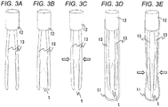
- Fig. 3A is a view showing a state before a biological tissue t is pinched.
- a description will be given by assuming that the same shape of the pinching surface as shown in Fig. 2B described above is adopted.
- a medical worker detaches the sealing member 12 and the pinching parts 13 from the container 11 beforehand.
- the pair of pinching parts 13 (13a and 13b) is in a state where the tips are separated from each other when a force is not applied thereto.
- a state where the biological tissue t is pinched is shown in Fig. 3B .
- the medical worker collects a biological tissue t with a size enabling the medical worker to pinch the tissue from a test subject (including not only a human being, but also an animal) in advance.
- the medical worker pinches the biological tissue t with the tips of the pinching parts 13 and presses the vicinity of the middle of the pinching parts 13 (in the middle of the connection point between the tips of the pinching parts 13 and the sealing member 12) from both sides.
- the medical worker pinches the biological tissue t with the tips of the pinching parts 13 and then applies a pressure in the direction where the distance between the pinching part 13a and the pinching part 13b is decreased. That is, the pinching part 13a and the pinching part 13b are configured to be openable or closable (preferably, capable of coming into or out of contact with each other) depending on whether it is pressed or not.
- Fig. 3C is a conceptual view showing a state after the biological tissue t is pinched with the pinching parts 13 and pressed.
- the medical worker applies a force (applies a force in the direction indicated by the arrows) so that the biological tissue t is crushed through the pinching parts 13 as described above.
- the biological tissue t is in a crushed state as compared with before it is pinched.
- the biological tissue t becomes soft by being crushed, and its surface area is increased. By increasing the surface area, cells are easily released from the biological tissue t.
- crushing the biological tissue t in this manner cells are in a state of being isolated (or in a state of being easily isolated) from the biological tissue t.
- the medical worker inserts the pinching parts 13 into the container 11 in a state where the biological tissue t is pinched while crushing. This state is shown in Fig. 3D .
- the medical worker inserts the biological tissue t and the pinching parts 13 into the container 11 and fits the sealing member 12 to the opening 11b (not shown in Fig. 3D ) of the container 11. By doing this, the biological tissue t crushed by pinching is in a state of being disposed in the container 11.
- the medical worker injects a reagent (not shown) and a cell treatment solution (not shown) into the container 11 in advance before the biological tissue t is inserted into the container 11.
- the reagent may be any as long as it contains, for example, a surfactant, an RNA (ribonucleic acid) remover, and a fluorescent dye or pigment.
- the cell treatment solution is desirably a solution having substantially the same osmotic pressure as the living body such as, for example, PBS (phosphate-buffered saline).
- the surfactant is used for nuclear isolation of the cells isolated from the biological tissue.
- the RNA remover removes RNA in the solution (the solution containing the isolated cells). Further, the fluorescent dye or pigment stains the cells subjected to nuclear isolation. By doing this, nuclear isolation of cells, removal of RNA, and staining of cells can be performed simultaneously with isolation of cells.
- Fig. 3E is a view showing a method for isolating cells from the biological tissue t in the container 11.
- the container 11 is soft such that it is bent by being pressed by the medical worker (which is soft such that it can be deformed by pressing).
- the Young's modulus of the container 11 may be, for example, about 0.1 GPa to 3 GPa.
- the medical worker applies a pressure so as to crush the container 11. By doing this, the container 11 is deformed, and a pressure is applied to the biological tissue t.
- the Young's modulus of the container 11 is preferably smaller than the Young's modulus of the pinching parts 13.
- the pinching parts 13 can apply a pressure to the biological tissue t while firmly pinching the biological tissue t.
- the medical worker repeatedly performs pressing and release of pressing for the biological tissue t through the container 11 (in other words, by alternately bringing the biological tissue t into the states of Fig. 3D and Fig. 3E a plurality of times), thereby, cells are isolated from the biological tissue t.
- the medical worker may perform isolation of cells from the biological tissue t by repeatedly performing pressing and release of pressing in a stage before placing the biological tissue t in the container 11 (that is, in a stage of Fig. 3C ).
- pressing beforehand becomes a necessary operation.
- the solution (the solution containing the isolated cells) is extracted from the container 11, and the cells are analyzed by a flow cytometer.
- the pinching parts 13 which pinch a biological tissue are provided in the sealing member 12.
- the sealing member 12 seals the opening 11b. Therefore, a medical worker can pinch (pick up) a biological tissue, and directly place the biological tissue in the container 11. Further, the medical worker can increase the surface area of the biological tissue by pressing when the biological tissue is pinched, and can isolate cells from the biological tissue. That is, the biological tissue can be disposed in the container 11 while pressing, and therefore, gripping of the biological tissue, transfer, and isolation can be smoothly performed in a series of flow.
- the pinching parts 13 can be configured such that the pinching surface has a corrugated shape ( Figs. 2B to 2D ). Since the pinching surface has ridges and grooves, the pinching parts 13 can increase the area where a pressure applied by the medical worker is applied to the biological tissue. According to this, the pressure applied by the medical worker can be efficiently transferred to the biological tissue, and thus, cells can be efficiently isolated from the biological tissue. Further, since the pinching surface has ridges and grooves, the pinching surface also functions as a slip-proof member, and can reduce the possibility that the biological tissue is dropped during transfer.
- the pinching parts 13 are in a state where the tips are open when they are not pressed by the medical worker ( Fig. 1 ). According to this, the medical worker can handle the biological tissue by the same operation as the operation of picking up the biological tissue with fingers.
- the container 11 is soft such that it is deformed by being pressed by the medical worker.
- the Young's modulus of the container 11 is preferably from about 0.1 to 3 GPa. According to this, the medical worker can crush the biological tissue from the outside of the container 11 (in other words, by deforming the container 11, a pressure can be applied to the biological tissue in the container 11).
- the Young's modulus of the pinching parts 13 is desirably higher than the Young's modulus of the container 11. That is, it is preferred that the material of the pinching parts 13 is harder than the material of the container 11. According to this, even if the container 11 is deformed by pressing, the pinching parts 13 are deformed less than the container 11. Since the pinching parts 13 are deformed less, a pressure can be applied to the biological tissue while firmly pinching the biological tissue with the pinching parts 13.
- the tips of the pinching parts 13 are in an open state when a pressure is not applied, however, a configuration in which the tips of the pinching parts 13 are closed when a pressure is not applied may be adopted. In this case, the tips of the pinching parts 13 will open when a pressure is applied. Even in this case, gripping of a biological tissue, transfer, and isolation can be smoothly performed.
- the shape of the pinching parts 13 described above is merely example, and may be another shape.
- a modification of the pinching parts 13 is shown in Fig. 4 .
- the pinching part 13a and the pinching part 13b are coupled with each other with a fulcrum member 13c.
- a medical worker performs pressing and release of pressing of the vicinity of the portion of attaching the pinching parts 13 to the sealing member 12 (for example, the portion indicated by the arrows in Fig. 4 ), thereby opening and closing the tips of the pinching part 13a and the pinching part 13b (bringing the tips into and out of contact with each other).
- a biological tissue can be pinched with the tips of the pinching part 13a and the pinching part 13b, and also cells can be isolated from the biological tissue by applying a pressure to the biological tissue when pinching the biological tissue. That is, gripping of a biological tissue, transfer, and isolation can be performed all together, and thus, the working efficiency of the medical worker can be improved.
- the pinching surfaces of the pinching part 13a and the pinching part 13b may be provided with ridges and grooves ( Figs. 2B to 2D ).
- Figs. 1 and 4 are merely examples, and anther configuration may be adopted as long as the open or closed state of the pinching parts 13 can be adjusted by pressing.
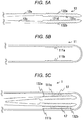
- Fig. 5A is an enlarged view showing a configuration example of the pinching parts 13 to be used when isolation of cells is performed by pressing a biological tissue against the container 11.
- ridges and grooves are provided in a part of an opposite surface 132a facing the pinching surface 131c.
- ridges and grooves are provided in a part of an opposite surface 132b facing the pinching surface 131d.
- the opposite surface 132a and the opposite surface 132b are pressed against the inner wall of the container 11 in the case where the pinching parts 13 are in an open state (in the case where the pinching part 13a and the pinching part 13b act so as to be separated from each other) .
- a biological tissue between the inner wall of the container 11 and the opposite surface 132a (or 132b), isolation of cells is performed.
- a shape in which the pinching surface 131c and the pinching surface 131d have ridges and grooves is adopted, however, the shape is not necessarily limited thereto, and may be another shape (for example, any configuration of Figs. 2A to 2D ).
- FIG. 5B shows a shape having ridges and grooves on the inner wall of the container 11. As shown in Fig. 5B , ridges and grooves are provided on an inner wall surface 111a and an inner wall surface 111b of the container 11.
- Fig. 5C is a view showing a concept of isolation of cells using the pinching parts 13 shown in Fig. 5A and the container 11 shown in Fig. 5B .
- a biological tissue t1 is sandwiched between the inner wall surface 111a and the opposite surface 132a. Cells are isolated from the biological tissue t1 by applying a pressure to the tissue while sandwiching the tissue.
- a biological tissue t2 is sandwiched between the inner wall surface 111b and the opposite surface 132b. Cells are isolated from the biological tissue t2 by applying a pressure to the tissue while sandwiching the tissue.
- the container 11 is soft such that it is bent by being pressed by a medical worker as described above.
- the biological tissues t1 and t2 can be pressed against the inner wall surface 111a and the inner wall surface 111b from the outside of the container 11.
- the shape ( Fig. 5B ) in which ridges and grooves are provided on the inner wall surface 111a and the inner wall surface 111b of the container 11 can also be used in combination with the shape of arbitrary pinching parts 13 (for example, a shape in which ridges and grooves are not provided on the opposite surface to the pinching surface as shown in Figs. 2A to 2D ).
- the shape of arbitrary pinching parts 13 for example, a shape in which ridges and grooves are not provided on the opposite surface to the pinching surface as shown in Figs. 2A to 2D .
- ridges and grooves are provided on the inner wall surface 111a and the inner wall surface 111b on the side surface of the container 11, however, ridges and grooves may be provided also on the round bottom surface of the container 11. That is, any shape may be adopted as long as it is a shape with ridges and grooves on a part of the inner wall of the container 11.
- the sealing member 12 may be provided with a filter.
- Fig. 6 is an exploded view according to the modification of the cell isolation instrument 10.
- the cell isolation instrument 10 includes a container 11, a sealing member 12, and pinching parts 13 in the same manner as the configuration of Fig. 1 .
- the sealing member 12 includes a large-diameter part 12a, a filter 12b, and a small-diameter part 12c.
- the large-diameter part 12a is a member which seals an opening 11b of the container 11.
- the outer diameter of the large-diameter part 12a is substantially the same as the diameter of the opening 11b of the container 11.
- the filter 12b is formed from a material free from cytotoxicity and has an aperture such that a solution containing isolated cells (cells subjected to nuclear isolation) can pass through the aperture.
- the filter 12b is a nylon mesh with an aperture of 50 ⁇ m.
- the filter 12b allows the solution containing the cells to pass therethrough to the small-diameter part 12c and also prohibits unnecessary substances from flowing to the small-diameter part 12c. That is, the filter 12b filters the solution in the container 11.
- the small-diameter part 12c is connected to a flow cytometer, and supplies a solution (a solution containing isolated cells) supplied from the filter 12b to the flow cytometer.
- the small-diameter part 12c may be connected to an apparatus other than the flow cytometer or a container such as a plate.
- a communication hole 12d for communicating the filter 12b with the upper end surface of the small-diameter part 12c is provided.
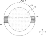
- Fig. 7 is a conceptual view in the case where the pinching parts 13 and the sealing member 12 are referred to from the -Y direction.
- the large-diameter part 12a has a cylindrical shape formed by hollowing out the central portion.
- the hollowed out portion constitutes a communication hole 12e through which a solution passes.
- the large-diameter part 12a can also be interpreted as a ring shape with a height.
- the filter 12b is disposed between the large-diameter part 12a and the small-diameter part 12c (not shown).
- the pinching part 13a and the pinching part 13b are connected to the bottom surface of the large-diameter part 12a.
- the pinching part 13a and the pinching part 13b may be fused to the bottom surface of the large-diameter part 12a, or may be fitted to a fitting opening of the large-diameter part 12a, or may be screwed to the large-diameter part 12a. That is, the pinching part 13a and the pinching part 13b may be connected to the large-diameter part 12a such that the tips are openable and closable (preferably, capable of coming into and out of contact with each other).
- a medical worker isolates cells from a biological tissue according to the procedure shown in Figs. 3A to 3E .
- the solution (the solution containing the isolated cells) is extracted from the container 11, and the cells are analyzed by a flow cytometer.
- the medical worker grips the cell isolation instrument 10 so that the communication hole 12d of the sealing member 12 faces the direction of gravitational force. By doing this, the solution moves to the direction of gravitational force, whereby the solution can be extracted.
- foreign substances are removed by the filter 12b.
- the extracted solution is in a state where the removal of RNA and the staining of the cells are completed, and therefore, the analysis by the flow cytometer can be immediately performed.
- the communication hole 12d and the communication hole 12e are provided in the sealing member 12, and also the filter 12b is provided between the communication hole 12d and the container 11.
- the filter 12b removes impurities from the solution (the solution containing the isolated cells). According to this, an analysis can be performed with less effect of impurities.
Landscapes
- Health & Medical Sciences (AREA)
- Life Sciences & Earth Sciences (AREA)
- General Health & Medical Sciences (AREA)
- Surgery (AREA)
- Chemical & Material Sciences (AREA)
- Molecular Biology (AREA)
- Public Health (AREA)
- Biomedical Technology (AREA)
- Heart & Thoracic Surgery (AREA)
- Medical Informatics (AREA)
- Engineering & Computer Science (AREA)
- Animal Behavior & Ethology (AREA)
- Veterinary Medicine (AREA)
- Pathology (AREA)
- Analytical Chemistry (AREA)
- Hematology (AREA)
- Clinical Laboratory Science (AREA)
- Chemical Kinetics & Catalysis (AREA)
- Nuclear Medicine, Radiotherapy & Molecular Imaging (AREA)
- Biodiversity & Conservation Biology (AREA)
- Apparatus Associated With Microorganisms And Enzymes (AREA)
- Sampling And Sample Adjustment (AREA)
Abstract
Description
- The present invention relates to a cell isolation instrument, and particularly relates to a cell isolation instrument, with which cells are isolated from a biological tissue.
- In a medical institution, a cytotechnologist or a pathologist makes a diagnosis using a section of tissue collected from a test subject. However, a specimen from a frozen section often results in an incomplete specimen. Further, the determination is difficult to make in some cases by the above-mentioned diagnosis in which only one cross section of a tissue can be observed. Therefore, a method in which cells are isolated from a biological tissue collected from a test subject and the cells are analyzed by a flow cytometer has been used.
- In a step of isolating cells from a biological tissue, a plurality of steps is required, and also a skilled technique is needed. Due to this, a technique for accurately and rapidly isolating cells has been demanded. In particular, a biological tissue associated with a digestive organ is fibrous, and therefore, it is necessary to accurately isolate cells from the biological tissue.
-
JP-A-2014-41018 - In the technique disclosed in the
above Patent Document 1, a treatment in which a biological tissue is placed in a container is performed, and thereafter a pressure is applied to the biological tissue, thereby isolating cells. In this manner, an isolation treatment is performed after a biological tissue is placed in a container, and therefore, the technique has a problem that a plurality of steps (gripping of a biological tissue, transfer, and isolation) cannot be smoothly performed continuously. - The invention has been made in view of the above problems, and a main object of the invention is to provide a cell isolation instrument capable of smoothly performing a plurality of steps (gripping of a biological tissue, transfer, and isolation) associated with isolation of cells.
- One aspect of a cell isolation instrument according to the invention includes:
- a container having an opening;
- a sealing member which seals the opening; and
- a pair of pinching parts which is connected to the sealing member and configured to be openable or closable by pressing.
- The pinching parts which pinch a biological tissue are provided in the sealing member. The sealing member is a member which seals the container having an opening. Therefore, a medical worker can pinch (pick up) a biological tissue, and directly place the biological tissue in the container, and seal the opening. In addition, the medical worker can isolate cells from the biological tissue by pressing when the biological tissue is pinched. That is, the biological tissue can be placed in the container while performing an isolation treatment, and therefore, gripping of a biological tissue, transfer, and isolation can be smoothly performed in a series of flow.
- According to the invention, a plurality of steps (gripping of a biological tissue, transfer, and isolation) associated with isolation of cells can be smoothly performed.
-
-
Fig. 1 is a perspective view showing the configuration of acell isolation instrument 10 according to a first embodiment. -
Figs. 2A to 2D are views each showing the structure of tips ofpinching parts 13 according to the first embodiment. -
Figs. 3A to 3E are schematic views showing the usage of thecell isolation instrument 10 according to the first embodiment. -
Fig. 4 is a view showing the configurations of a sealingmember 12 andpinching parts 13 according to the first embodiment. -
Figs. 5A to 5C are views each showing the configurations ofpinching parts 13 and acontainer 11 according to a modification of the first embodiment. -
Fig. 6 is a perspective view showing the configuration of acell isolation instrument 10 according to a modification of the first embodiment. -
Fig. 7 is a view showing the configurations of a sealingmember 12 andpinching parts 13 according to a modification of the first embodiment. - Hereinafter, embodiments of the invention will be described with reference to the drawings. In the respective drawings, the reduction scale or the like is changed as appropriate so that each member has a recognizable size.
- First, the configuration of a
cell isolation instrument 10 according to this embodiment will be described.Fig. 1 shows thecell isolation instrument 10. Thecell isolation instrument 10 includes acontainer 11, a sealingmember 12, andpinching parts 13. - The
container 11 is a cylindrical member in which anupper end surface 11a has an opening 11b and a lower end portion is a round bottom. Thecontainer 11 is desirably transparent and is desirably capable of visually recognizing a hollowinner space 11c. Theinner space 11c communicates with the opening 11b. Thecontainer 11 may be, for example, a glass test tube or the like, but is more preferably constituted by a material which is soft such that it is bent by pressing. For example, thecontainer 11 is preferably constituted by a synthetic resin such as polypropylene or polyethylene. In other words, thecontainer 11 desirably has an elasticity of about 0.1 to 3 GPa. - The sealing
member 12 is a member which seals the opening 11b of thecontainer 11. The outer diameter of the sealingmember 12 is substantially equal to the diameter of the opening 11b of thecontainer 11. By inserting the sealingmember 12 into the opening 11b, the sealingmember 12 is fixed to thecontainer 11. To an insertion surface of the sealingmember 12 into the opening 11b, thepinching parts 13 are connected. - The sealing
member 12 may have any shape as long as it can seal thecontainer 11. For example, a groove with a corresponding shape is provided in each of the inner peripheral surface of thecontainer 11 and the outer peripheral surface of thesealing member 12, and sealing may be performed by rotating thesealing member 12 in a state where the groove of the sealingmember 12 is fitted to the groove of thecontainer 11. Alternatively, the sealingmember 12 is constituted by an elastic member (for example, rubber), and sealing may be performed by inserting the sealingmember 12 into the opening 11b of thecontainer 11. The "sealing" in this embodiment is not necessarily used in a way that thecontainer 11 is closed and brought into a hermetically sealed state, but may be used in a way that the sealingmember 12 and thepinching parts 13 can be disposed (or fixed) in thecontainer 11. - The
pinching parts 13 are connected to a lower end portion (an insertion surface into the opening 11b) of thesealing member 12. Thepinching parts 13 are a pair of members (13a and 13b), and pinch a biological tissue and apply a pressure thereto as will be described later. Thepinching parts 13 are in a state where the tips (an opposite direction to a connecting surface to the sealing member 12) are open when they are not pressed (when a force is not applied), and in the case where thepinching parts 13 are pressed from both sides in a short-side direction (which will be described later with reference toFig. 3E ), the tips are closed. Thepinching parts 13 pinch a biological tissue and also act so as to crush the biological tissue. The pressing of a biological tissue by the pinching parts 13 (in other words, isolation of cells from a biological tissue) will be described later with reference toFigs. 3A to 3E . - Incidentally, the pinching surface of the
pinching part 13 desirably has a larger area than the connecting portion (in other words, a connection portion to the sealing member 12) of thepinching part 13. According to this, a biological tissue can be reliably pinched. The pinching surface refers to a place where a biological tissue is pinched. - In the following description, the direction toward the lower end of the
container 11 is defined as "-Y direction", the direction toward the upper end thereof (the direction toward the opening) is defined as "+Y direction", the opening and closing direction of the pinchingparts 13 is defined as "X direction (+X direction and -X direction) ", and a direction orthogonal to the opening and closing direction of the pinchingpart 13 is defined as "Z direction (+Z direction and -Z direction)". -
Figs. 2A to 2D are enlarged views showing examples of the configuration of the tip portions of the pinching parts 13 (13a and 13b). In an example ofFig. 2A , the pinchingsurfaces parts 13 have a substantially planar shape. In an example ofFig. 2B , the pinching surfaces 131c and 131d of the pinchingparts 13 have a shape provided with ridges and grooves. In an example ofFig. 2C , the pinchingsurface 131e of the pinchingpart 13 has a corrugated shape like a so-called spiky frog (provided with a plurality of columnar bodies with a fine sharp tip). In an example ofFig. 2D , both of the pinching surfaces 131g and 131h of the pinchingparts 13 have a corrugated shape like a so-called spiky frog (provided with a plurality of columnar bodies with a fine sharp tip). The pinchingparts 13 may have any of the configurations ofFigs. 2A to 2D , however, in the configurations ofFigs. 2B to 2D , ridges and grooves are provided on the pinching surfaces (131c, 131d, 131e, 131g, and 131h) which pinch a biological tissue. Due to this, in the configurations ofFigs. 2B to 2D , even if the force to be applied is low, the biological tissue can be pressed strongly. Incidentally, inFigs. 2B to 2D , it is more preferred that ridges and grooves are provided on the entire pinching surface, however, ridges and grooves may be provided on only a portion of the pinching surface. - Then, the usage of the
cell isolation instrument 10 will be described with reference toFigs. 3A to 3E. Fig. 3A is a view showing a state before a biological tissue t is pinched. Incidentally, in the following description, a description will be given by assuming that the same shape of the pinching surface as shown inFig. 2B described above is adopted. In a stage before using thecell isolation instrument 10, a medical worker detaches the sealingmember 12 and the pinchingparts 13 from thecontainer 11 beforehand. As described above, the pair of pinching parts 13 (13a and 13b) is in a state where the tips are separated from each other when a force is not applied thereto. - Subsequently, a state where the biological tissue t is pinched is shown in
Fig. 3B . The medical worker collects a biological tissue t with a size enabling the medical worker to pinch the tissue from a test subject (including not only a human being, but also an animal) in advance. The medical worker pinches the biological tissue t with the tips of the pinchingparts 13 and presses the vicinity of the middle of the pinching parts 13 (in the middle of the connection point between the tips of the pinchingparts 13 and the sealing member 12) from both sides. In other words, the medical worker pinches the biological tissue t with the tips of the pinchingparts 13 and then applies a pressure in the direction where the distance between the pinchingpart 13a and the pinchingpart 13b is decreased. That is, the pinchingpart 13a and the pinchingpart 13b are configured to be openable or closable (preferably, capable of coming into or out of contact with each other) depending on whether it is pressed or not. -
Fig. 3C is a conceptual view showing a state after the biological tissue t is pinched with the pinchingparts 13 and pressed. The medical worker applies a force (applies a force in the direction indicated by the arrows) so that the biological tissue t is crushed through the pinchingparts 13 as described above. By doing this, the biological tissue t is in a crushed state as compared with before it is pinched. The biological tissue t becomes soft by being crushed, and its surface area is increased. By increasing the surface area, cells are easily released from the biological tissue t. By crushing the biological tissue t in this manner, cells are in a state of being isolated (or in a state of being easily isolated) from the biological tissue t. - The medical worker inserts the pinching
parts 13 into thecontainer 11 in a state where the biological tissue t is pinched while crushing. This state is shown inFig. 3D . The medical worker inserts the biological tissue t and the pinchingparts 13 into thecontainer 11 and fits the sealingmember 12 to theopening 11b (not shown inFig. 3D ) of thecontainer 11. By doing this, the biological tissue t crushed by pinching is in a state of being disposed in thecontainer 11. - Incidentally, although not shown in the drawing, the medical worker injects a reagent (not shown) and a cell treatment solution (not shown) into the
container 11 in advance before the biological tissue t is inserted into thecontainer 11. The reagent may be any as long as it contains, for example, a surfactant, an RNA (ribonucleic acid) remover, and a fluorescent dye or pigment. The cell treatment solution is desirably a solution having substantially the same osmotic pressure as the living body such as, for example, PBS (phosphate-buffered saline). - The surfactant is used for nuclear isolation of the cells isolated from the biological tissue. The RNA remover removes RNA in the solution (the solution containing the isolated cells). Further, the fluorescent dye or pigment stains the cells subjected to nuclear isolation. By doing this, nuclear isolation of cells, removal of RNA, and staining of cells can be performed simultaneously with isolation of cells.
- The medical worker further applies a pressure to the biological tissue t after disposing the biological tissue t in the
container 11, thereby isolating cells.Fig. 3E is a view showing a method for isolating cells from the biological tissue t in thecontainer 11. - As described above, the
container 11 is soft such that it is bent by being pressed by the medical worker (which is soft such that it can be deformed by pressing). The Young's modulus of thecontainer 11 may be, for example, about 0.1 GPa to 3 GPa. The medical worker applies a pressure so as to crush thecontainer 11. By doing this, thecontainer 11 is deformed, and a pressure is applied to the biological tissue t. Here, the Young's modulus of thecontainer 11 is preferably smaller than the Young's modulus of the pinchingparts 13. According to this relationship of the Young's modulus (the Young's modulus of thecontainer 11 is smaller than the Young' s modulus of the pinching parts 13), the pinchingparts 13 can apply a pressure to the biological tissue t while firmly pinching the biological tissue t. The medical worker repeatedly performs pressing and release of pressing for the biological tissue t through the container 11 (in other words, by alternately bringing the biological tissue t into the states ofFig. 3D and Fig. 3E a plurality of times), thereby, cells are isolated from the biological tissue t. - Incidentally, the medical worker may perform isolation of cells from the biological tissue t by repeatedly performing pressing and release of pressing in a stage before placing the biological tissue t in the container 11 (that is, in a stage of
Fig. 3C ). In the case where thecontainer 11 is constituted by a hard material which is not deformed by pressing, pressing beforehand becomes a necessary operation. - In the case where the medical worker determines that cells could be sufficiently isolated from the biological tissue t, the solution (the solution containing the isolated cells) is extracted from the
container 11, and the cells are analyzed by a flow cytometer. - Next, an effect of the
cell isolation instrument 10 according to this embodiment will be described. As described above, the pinchingparts 13 which pinch a biological tissue are provided in the sealingmember 12. The sealingmember 12 seals theopening 11b. Therefore, a medical worker can pinch (pick up) a biological tissue, and directly place the biological tissue in thecontainer 11. Further, the medical worker can increase the surface area of the biological tissue by pressing when the biological tissue is pinched, and can isolate cells from the biological tissue. That is, the biological tissue can be disposed in thecontainer 11 while pressing, and therefore, gripping of the biological tissue, transfer, and isolation can be smoothly performed in a series of flow. - Further, the pinching
parts 13 can be configured such that the pinching surface has a corrugated shape (Figs. 2B to 2D ). Since the pinching surface has ridges and grooves, the pinchingparts 13 can increase the area where a pressure applied by the medical worker is applied to the biological tissue. According to this, the pressure applied by the medical worker can be efficiently transferred to the biological tissue, and thus, cells can be efficiently isolated from the biological tissue. Further, since the pinching surface has ridges and grooves, the pinching surface also functions as a slip-proof member, and can reduce the possibility that the biological tissue is dropped during transfer. - Further, it is preferred that the pinching
parts 13 are in a state where the tips are open when they are not pressed by the medical worker (Fig. 1 ). According to this, the medical worker can handle the biological tissue by the same operation as the operation of picking up the biological tissue with fingers. - Further, it is preferred that the
container 11 is soft such that it is deformed by being pressed by the medical worker. For example, the Young's modulus of thecontainer 11 is preferably from about 0.1 to 3 GPa. According to this, the medical worker can crush the biological tissue from the outside of the container 11 (in other words, by deforming thecontainer 11, a pressure can be applied to the biological tissue in the container 11). - Here, the Young's modulus of the pinching
parts 13 is desirably higher than the Young's modulus of thecontainer 11. That is, it is preferred that the material of the pinchingparts 13 is harder than the material of thecontainer 11. According to this, even if thecontainer 11 is deformed by pressing, the pinchingparts 13 are deformed less than thecontainer 11. Since the pinchingparts 13 are deformed less, a pressure can be applied to the biological tissue while firmly pinching the biological tissue with the pinchingparts 13. - Hereinabove, the invention made by the present inventors has been specifically described based on the embodiments, however, the invention is not limited to the previously described embodiments, and it is a matter of course that various modifications may be made without departing from the gist of the invention. Hereinafter, modifications will be described.
- In the above-mentioned configuration, it is described that the tips of the pinching
parts 13 are in an open state when a pressure is not applied, however, a configuration in which the tips of the pinchingparts 13 are closed when a pressure is not applied may be adopted. In this case, the tips of the pinchingparts 13 will open when a pressure is applied. Even in this case, gripping of a biological tissue, transfer, and isolation can be smoothly performed. - The shape of the pinching
parts 13 described above is merely example, and may be another shape. A modification of the pinchingparts 13 is shown inFig. 4 . In this modification, the pinchingpart 13a and the pinchingpart 13b are coupled with each other with afulcrum member 13c. A medical worker performs pressing and release of pressing of the vicinity of the portion of attaching the pinchingparts 13 to the sealing member 12 (for example, the portion indicated by the arrows inFig. 4 ), thereby opening and closing the tips of the pinchingpart 13a and the pinchingpart 13b (bringing the tips into and out of contact with each other). - Even in the case of this configuration, a biological tissue can be pinched with the tips of the pinching
part 13a and the pinchingpart 13b, and also cells can be isolated from the biological tissue by applying a pressure to the biological tissue when pinching the biological tissue. That is, gripping of a biological tissue, transfer, and isolation can be performed all together, and thus, the working efficiency of the medical worker can be improved. - Also in the configuration of
Fig. 4 , the pinching surfaces of the pinchingpart 13a and the pinchingpart 13b may be provided with ridges and grooves (Figs. 2B to 2D ). - Incidentally, the configurations of
Figs. 1 and4 are merely examples, and anther configuration may be adopted as long as the open or closed state of the pinchingparts 13 can be adjusted by pressing. - In the above description, a description has been given by assuming that a biological tissue is pinched with the pinching surfaces 131 of the pinching
parts 13 and pressed, however, isolation of cells may be performed by pressing a biological tissue against thecontainer 11. A configuration when using this method is shown inFigs. 5A to 5C . -
Fig. 5A is an enlarged view showing a configuration example of the pinchingparts 13 to be used when isolation of cells is performed by pressing a biological tissue against thecontainer 11. As shown inFig. 5A , ridges and grooves are provided in a part of anopposite surface 132a facing the pinchingsurface 131c. In the same manner, ridges and grooves are provided in a part of anopposite surface 132b facing the pinchingsurface 131d. Theopposite surface 132a and theopposite surface 132b are pressed against the inner wall of thecontainer 11 in the case where the pinchingparts 13 are in an open state (in the case where the pinchingpart 13a and the pinchingpart 13b act so as to be separated from each other) . At this time, by sandwiching a biological tissue between the inner wall of thecontainer 11 and theopposite surface 132a (or 132b), isolation of cells is performed. Incidentally, inFig. 5A , a shape in which the pinchingsurface 131c and the pinchingsurface 131d have ridges and grooves is adopted, however, the shape is not necessarily limited thereto, and may be another shape (for example, any configuration ofFigs. 2A to 2D ). - Incidentally, by providing ridges and grooves also in the inner wall of the
container 11, isolation of cells can be more efficiently performed.Fig. 5B shows a shape having ridges and grooves on the inner wall of thecontainer 11. As shown inFig. 5B , ridges and grooves are provided on aninner wall surface 111a and aninner wall surface 111b of thecontainer 11. -
Fig. 5C is a view showing a concept of isolation of cells using the pinchingparts 13 shown inFig. 5A and thecontainer 11 shown inFig. 5B . As shown inFig. 5C , a biological tissue t1 is sandwiched between theinner wall surface 111a and theopposite surface 132a. Cells are isolated from the biological tissue t1 by applying a pressure to the tissue while sandwiching the tissue. In the same manner, a biological tissue t2 is sandwiched between theinner wall surface 111b and theopposite surface 132b. Cells are isolated from the biological tissue t2 by applying a pressure to the tissue while sandwiching the tissue. - Even in the case of the configuration (
Figs. 5A and 5B ), gripping of a biological tissue, transfer, and isolation can be smoothly performed. - Incidentally, even in the case of the third modification, it is preferred that the
container 11 is soft such that it is bent by being pressed by a medical worker as described above. By pressing thecontainer 11 by the medical worker, the biological tissues t1 and t2 can be pressed against theinner wall surface 111a and theinner wall surface 111b from the outside of thecontainer 11. - Incidentally, the shape (
Fig. 5B ) in which ridges and grooves are provided on theinner wall surface 111a and theinner wall surface 111b of thecontainer 11 can also be used in combination with the shape of arbitrary pinching parts 13 (for example, a shape in which ridges and grooves are not provided on the opposite surface to the pinching surface as shown inFigs. 2A to 2D ). By bringing a biological tissue into contact with theinner wall surface 111a and theinner wall surface 111b having ridges and grooves, cells are in a state of being easily isolated from the biological tissue. - Incidentally, in the example of
Fig. 5B , ridges and grooves are provided on theinner wall surface 111a and theinner wall surface 111b on the side surface of thecontainer 11, however, ridges and grooves may be provided also on the round bottom surface of thecontainer 11. That is, any shape may be adopted as long as it is a shape with ridges and grooves on a part of the inner wall of thecontainer 11. - The sealing
member 12 may be provided with a filter. This configuration example will be described with reference toFigs. 6 and7 .Fig. 6 is an exploded view according to the modification of thecell isolation instrument 10. Thecell isolation instrument 10 includes acontainer 11, a sealingmember 12, and pinchingparts 13 in the same manner as the configuration ofFig. 1 . - In this modification, the sealing
member 12 includes a large-diameter part 12a, afilter 12b, and a small-diameter part 12c. The large-diameter part 12a is a member which seals anopening 11b of thecontainer 11. The outer diameter of the large-diameter part 12a is substantially the same as the diameter of theopening 11b of thecontainer 11. By inserting the large-diameter part 12a into theopening 11b, the sealingmember 12 is fixed to thecontainer 11. To the insertion surface of the large-diameter part 12a into theopening 11b, the pinchingparts 13 are connected. In the large-diameter part 12a, acommunication hole 12e for communicating a solution (a solution containing isolated cells) placed in thecontainer 11 with thefilter 12b is provided. - The
filter 12b is formed from a material free from cytotoxicity and has an aperture such that a solution containing isolated cells (cells subjected to nuclear isolation) can pass through the aperture. For example, thefilter 12b is a nylon mesh with an aperture of 50 µm. Thefilter 12b allows the solution containing the cells to pass therethrough to the small-diameter part 12c and also prohibits unnecessary substances from flowing to the small-diameter part 12c. That is, thefilter 12b filters the solution in thecontainer 11. - The small-
diameter part 12c is connected to a flow cytometer, and supplies a solution (a solution containing isolated cells) supplied from thefilter 12b to the flow cytometer. Incidentally, the small-diameter part 12c may be connected to an apparatus other than the flow cytometer or a container such as a plate. In the small-diameter part 12c, acommunication hole 12d for communicating thefilter 12b with the upper end surface of the small-diameter part 12c is provided. -
Fig. 7 is a conceptual view in the case where the pinchingparts 13 and the sealingmember 12 are referred to from the -Y direction. As shown inFig. 7 , the large-diameter part 12a has a cylindrical shape formed by hollowing out the central portion. The hollowed out portion constitutes acommunication hole 12e through which a solution passes. In other words, the large-diameter part 12a can also be interpreted as a ring shape with a height. Thefilter 12b is disposed between the large-diameter part 12a and the small-diameter part 12c (not shown). - The pinching
part 13a and the pinchingpart 13b are connected to the bottom surface of the large-diameter part 12a. For example, the pinchingpart 13a and the pinchingpart 13b may be fused to the bottom surface of the large-diameter part 12a, or may be fitted to a fitting opening of the large-diameter part 12a, or may be screwed to the large-diameter part 12a. That is, the pinchingpart 13a and the pinchingpart 13b may be connected to the large-diameter part 12a such that the tips are openable and closable (preferably, capable of coming into and out of contact with each other). - A medical worker isolates cells from a biological tissue according to the procedure shown in
Figs. 3A to 3E . In the case where it is determined that cells could be sufficiently isolated from a biological tissue, the solution (the solution containing the isolated cells) is extracted from thecontainer 11, and the cells are analyzed by a flow cytometer. For example, the medical worker grips thecell isolation instrument 10 so that thecommunication hole 12d of the sealingmember 12 faces the direction of gravitational force. By doing this, the solution moves to the direction of gravitational force, whereby the solution can be extracted. Incidentally, foreign substances are removed by thefilter 12b. The extracted solution is in a state where the removal of RNA and the staining of the cells are completed, and therefore, the analysis by the flow cytometer can be immediately performed. Incidentally, it is also possible to extract the solution from thecell isolation instrument 10 in a state where thecommunication hole 12d is fitted with a nozzle of the flow cytometer. - In the above-mentioned modification (
Figs. 6 and7 ), thecommunication hole 12d and thecommunication hole 12e are provided in the sealingmember 12, and also thefilter 12b is provided between thecommunication hole 12d and thecontainer 11. Thefilter 12b removes impurities from the solution (the solution containing the isolated cells). According to this, an analysis can be performed with less effect of impurities.
Claims (8)
- A cell isolation instrument (10), comprising:a container (11) having an opening;a sealing member (12) which seals the opening; anda pair of pinching parts (13a, 13b) which is connected to the sealing member (12) and configured to be openable or closable by pressing.
- The cell isolation instrument (10) according to claim 1, wherein the pair of pinching parts (13a, 13b) is provided with ridges and grooves in at least a portion of a pinching surface for pinching a biological tissue.
- The cell isolation instrument (10) according to claim 1 or 2, wherein the pair of pinching parts (13a, 13b) is in a state where tips are open when a force is not applied thereto.
- The cell isolation instrument (10) according to any one of claims 1 to 3, wherein the container (11) is configured to be deformable by pressing.
- The cell isolation instrument (10) according to any one of claims 1 to 4, wherein the container (11) has a smaller Young's modulus than the pair of pinching parts (13a, 13b).
- The cell isolation instrument (10) according to any one of claims 1 to 5, wherein the container (11) is provided with ridges and grooves in at least a portion of an inner wall surface thereof.
- The cell isolation instrument (10) according to any one of claims 1 to 6, wherein the pair of pinching parts (13a, 13b) is provided with ridges and grooves in at least a portion of an opposite surface to a pinching surface for pinching a biological tissue.
- The cell isolation instrument (10) according to any one of claims 1 to 7, wherein the sealing member (12) includes a communication hole for communicating a solution containing isolated cells and a filter for filtering the solution provided for the communication hole.
Applications Claiming Priority (1)
| Application Number | Priority Date | Filing Date | Title |
|---|---|---|---|
| JP2016003181A JP6694714B2 (en) | 2016-01-12 | 2016-01-12 | Cell isolation instrument |
Publications (2)
| Publication Number | Publication Date |
|---|---|
| EP3192450A1 true EP3192450A1 (en) | 2017-07-19 |
| EP3192450B1 EP3192450B1 (en) | 2021-08-18 |
Family
ID=57777465
Family Applications (1)
| Application Number | Title | Priority Date | Filing Date |
|---|---|---|---|
| EP16207519.6A Active EP3192450B1 (en) | 2016-01-12 | 2016-12-30 | Cell isolation instrument |
Country Status (3)
| Country | Link |
|---|---|
| US (1) | US11553904B2 (en) |
| EP (1) | EP3192450B1 (en) |
| JP (1) | JP6694714B2 (en) |
Cited By (1)
| Publication number | Priority date | Publication date | Assignee | Title |
|---|---|---|---|---|
| DE102021200214A1 (en) | 2021-01-12 | 2022-07-14 | Anvajo GmbH | sample receiving device |
Citations (5)
| Publication number | Priority date | Publication date | Assignee | Title |
|---|---|---|---|---|
| JPH01136460U (en) * | 1988-03-10 | 1989-09-19 | ||
| US20110020860A1 (en) * | 2008-12-29 | 2011-01-27 | Greenwald Robert J | Fecal examination method and collection container |
| US20110146420A1 (en) * | 2008-08-29 | 2011-06-23 | Olympus Corporation | Container for specimen |
| US20130345596A1 (en) * | 2012-06-25 | 2013-12-26 | David S. Zimmon | Apparatus and methods for removing and collecting biopsy specimens from biopsy devices with fixation and preparation for histopathological processing or other analysis |
| JP2014041018A (en) | 2012-08-21 | 2014-03-06 | Sysmex Corp | Crushing processor |
Family Cites Families (12)
| Publication number | Priority date | Publication date | Assignee | Title |
|---|---|---|---|---|
| US3080760A (en) * | 1960-06-29 | 1963-03-12 | American Cyanamid Co | Disposable sample probe for bulk chemicals |
| USB663271I5 (en) * | 1967-04-24 | |||
| US3705018A (en) * | 1970-06-10 | 1972-12-05 | Billy W Taylor | Resealable test tube |
| US4690153A (en) * | 1985-11-29 | 1987-09-01 | Becton, Dickinson And Company | Flow inducing means for small volume containers |
| US4967763A (en) * | 1989-03-13 | 1990-11-06 | Becton, Dickinson And Company | Platelet stable blood collection assembly |
| JPH0344664U (en) * | 1989-09-07 | 1991-04-25 | ||
| US5269804A (en) * | 1991-04-04 | 1993-12-14 | Symbiosis Corporation | Endoscopic colo-rectal bowel clamp |
| US20050125013A1 (en) * | 2003-11-14 | 2005-06-09 | Alan Kessler | Safety surgical forceps |
| JP5297816B2 (en) * | 2007-01-26 | 2013-09-25 | オリンパスメディカルシステムズ株式会社 | Gripping device |
| JP2009036732A (en) * | 2007-08-03 | 2009-02-19 | Rohto Pharmaceut Co Ltd | Container for extraction |
| JP2013255447A (en) * | 2012-06-12 | 2013-12-26 | Nippon Koden Corp | Cell isolation apparatus |
| US9839913B2 (en) * | 2014-07-14 | 2017-12-12 | Maria Lotosky-Compton | Medical specimen container |
-
2016
- 2016-01-12 JP JP2016003181A patent/JP6694714B2/en not_active Expired - Fee Related
- 2016-12-30 EP EP16207519.6A patent/EP3192450B1/en active Active
-
2017
- 2017-01-11 US US15/403,941 patent/US11553904B2/en active Active
Patent Citations (5)
| Publication number | Priority date | Publication date | Assignee | Title |
|---|---|---|---|---|
| JPH01136460U (en) * | 1988-03-10 | 1989-09-19 | ||
| US20110146420A1 (en) * | 2008-08-29 | 2011-06-23 | Olympus Corporation | Container for specimen |
| US20110020860A1 (en) * | 2008-12-29 | 2011-01-27 | Greenwald Robert J | Fecal examination method and collection container |
| US20130345596A1 (en) * | 2012-06-25 | 2013-12-26 | David S. Zimmon | Apparatus and methods for removing and collecting biopsy specimens from biopsy devices with fixation and preparation for histopathological processing or other analysis |
| JP2014041018A (en) | 2012-08-21 | 2014-03-06 | Sysmex Corp | Crushing processor |
Cited By (1)
| Publication number | Priority date | Publication date | Assignee | Title |
|---|---|---|---|---|
| DE102021200214A1 (en) | 2021-01-12 | 2022-07-14 | Anvajo GmbH | sample receiving device |
Also Published As
| Publication number | Publication date |
|---|---|
| US20170196544A1 (en) | 2017-07-13 |
| JP6694714B2 (en) | 2020-05-20 |
| JP2017123785A (en) | 2017-07-20 |
| EP3192450B1 (en) | 2021-08-18 |
| US11553904B2 (en) | 2023-01-17 |
Similar Documents
| Publication | Publication Date | Title |
|---|---|---|
| US5000193A (en) | Medical swab device | |
| EP1740722B1 (en) | Method and assembly for dna isolation with dry reagents | |
| WO2011095599A1 (en) | Test kit | |
| JP2018512569A (en) | Assembly for storing and transporting a tissue sample immersed in a fluid | |
| US8474337B2 (en) | Extraction method, extraction vessel for use with the same, extraction kit and valve expansion member | |
| US20080241874A1 (en) | Method and device for manipulating individual small objects | |
| KR102159936B1 (en) | Specimen vial container configured to mix plurality of liquid by pressing cap | |
| DE10319045A1 (en) | Device and method for processing liquids containing biopolymers | |
| US20090084202A1 (en) | Sample Trituration Vessel, Tool and Method Using The Same | |
| EP4331486A2 (en) | Sample collection device, system and method for extracting and collecting a sample of a fluid of a user | |
| US20090100915A1 (en) | Method of Sampling Specimen, Test Method and Dropping Pipette and Specimen Sampler to be Used Therein | |
| US20210291181A1 (en) | Seal component for a rapid diagnostic test | |
| EP3165173B1 (en) | Splittable fluid sample collector | |
| CN108027302A (en) | Devices for collecting, transferring and storing samples of biological and/or chemical material | |
| EP3192450B1 (en) | Cell isolation instrument | |
| EP1934574B1 (en) | Sampling system for fluid samples | |
| WO2010131140A1 (en) | Biological sample collection device | |
| DE69609961T2 (en) | DEVICE AND METHOD FOR THE EXAMINATION OF LIQUIDS | |
| Berry et al. | Dermal ISF collection using a Si microneedle array | |
| WO2017087703A1 (en) | Sample processing and smearing apparatus and methods | |
| US11446666B2 (en) | Fluid handling device | |
| DE102016009414A1 (en) | Device for transferring sample material into a liquid | |
| WO2005053514A2 (en) | Specimen collection and processing device | |
| KR101773265B1 (en) | Reagent stick for analyzing bacteria, method for analyzing bacteria using the reagent stick | |
| EP2834006A1 (en) | Chamber component for a reagent vessel, and use thereof |
Legal Events
| Date | Code | Title | Description |
|---|---|---|---|
| PUAI | Public reference made under article 153(3) epc to a published international application that has entered the european phase |
Free format text: ORIGINAL CODE: 0009012 |
|
| STAA | Information on the status of an ep patent application or granted ep patent |
Free format text: STATUS: THE APPLICATION HAS BEEN PUBLISHED |
|
| AK | Designated contracting states |
Kind code of ref document: A1 Designated state(s): AL AT BE BG CH CY CZ DE DK EE ES FI FR GB GR HR HU IE IS IT LI LT LU LV MC MK MT NL NO PL PT RO RS SE SI SK SM TR |
|
| AX | Request for extension of the european patent |
Extension state: BA ME |
|
| STAA | Information on the status of an ep patent application or granted ep patent |
Free format text: STATUS: REQUEST FOR EXAMINATION WAS MADE |
|
| 17P | Request for examination filed |
Effective date: 20171116 |
|
| RBV | Designated contracting states (corrected) |
Designated state(s): AL AT BE BG CH CY CZ DE DK EE ES FI FR GB GR HR HU IE IS IT LI LT LU LV MC MK MT NL NO PL PT RO RS SE SI SK SM TR |
|
| STAA | Information on the status of an ep patent application or granted ep patent |
Free format text: STATUS: EXAMINATION IS IN PROGRESS |
|
| 17Q | First examination report despatched |
Effective date: 20190118 |
|
| GRAP | Despatch of communication of intention to grant a patent |
Free format text: ORIGINAL CODE: EPIDOSNIGR1 |
|
| STAA | Information on the status of an ep patent application or granted ep patent |
Free format text: STATUS: GRANT OF PATENT IS INTENDED |
|
| INTG | Intention to grant announced |
Effective date: 20210526 |
|
| GRAS | Grant fee paid |
Free format text: ORIGINAL CODE: EPIDOSNIGR3 |
|
| GRAA | (expected) grant |
Free format text: ORIGINAL CODE: 0009210 |
|
| STAA | Information on the status of an ep patent application or granted ep patent |
Free format text: STATUS: THE PATENT HAS BEEN GRANTED |
|
| AK | Designated contracting states |
Kind code of ref document: B1 Designated state(s): AL AT BE BG CH CY CZ DE DK EE ES FI FR GB GR HR HU IE IS IT LI LT LU LV MC MK MT NL NO PL PT RO RS SE SI SK SM TR |
|
| REG | Reference to a national code |
Ref country code: GB Ref legal event code: FG4D |
|
| REG | Reference to a national code |
Ref country code: CH Ref legal event code: EP |
|
| REG | Reference to a national code |
Ref country code: DE Ref legal event code: R096 Ref document number: 602016062319 Country of ref document: DE |
|
| REG | Reference to a national code |
Ref country code: IE Ref legal event code: FG4D Ref country code: AT Ref legal event code: REF Ref document number: 1420904 Country of ref document: AT Kind code of ref document: T Effective date: 20210915 |
|
| REG | Reference to a national code |
Ref country code: LT Ref legal event code: MG9D |
|
| REG | Reference to a national code |
Ref country code: NL Ref legal event code: MP Effective date: 20210818 |
|
| REG | Reference to a national code |
Ref country code: AT Ref legal event code: MK05 Ref document number: 1420904 Country of ref document: AT Kind code of ref document: T Effective date: 20210818 |
|
| PG25 | Lapsed in a contracting state [announced via postgrant information from national office to epo] |
Ref country code: RS Free format text: LAPSE BECAUSE OF FAILURE TO SUBMIT A TRANSLATION OF THE DESCRIPTION OR TO PAY THE FEE WITHIN THE PRESCRIBED TIME-LIMIT Effective date: 20210818 Ref country code: SE Free format text: LAPSE BECAUSE OF FAILURE TO SUBMIT A TRANSLATION OF THE DESCRIPTION OR TO PAY THE FEE WITHIN THE PRESCRIBED TIME-LIMIT Effective date: 20210818 Ref country code: HR Free format text: LAPSE BECAUSE OF FAILURE TO SUBMIT A TRANSLATION OF THE DESCRIPTION OR TO PAY THE FEE WITHIN THE PRESCRIBED TIME-LIMIT Effective date: 20210818 Ref country code: FI Free format text: LAPSE BECAUSE OF FAILURE TO SUBMIT A TRANSLATION OF THE DESCRIPTION OR TO PAY THE FEE WITHIN THE PRESCRIBED TIME-LIMIT Effective date: 20210818 Ref country code: ES Free format text: LAPSE BECAUSE OF FAILURE TO SUBMIT A TRANSLATION OF THE DESCRIPTION OR TO PAY THE FEE WITHIN THE PRESCRIBED TIME-LIMIT Effective date: 20210818 Ref country code: NO Free format text: LAPSE BECAUSE OF FAILURE TO SUBMIT A TRANSLATION OF THE DESCRIPTION OR TO PAY THE FEE WITHIN THE PRESCRIBED TIME-LIMIT Effective date: 20211118 Ref country code: PT Free format text: LAPSE BECAUSE OF FAILURE TO SUBMIT A TRANSLATION OF THE DESCRIPTION OR TO PAY THE FEE WITHIN THE PRESCRIBED TIME-LIMIT Effective date: 20211220 Ref country code: LT Free format text: LAPSE BECAUSE OF FAILURE TO SUBMIT A TRANSLATION OF THE DESCRIPTION OR TO PAY THE FEE WITHIN THE PRESCRIBED TIME-LIMIT Effective date: 20210818 Ref country code: AT Free format text: LAPSE BECAUSE OF FAILURE TO SUBMIT A TRANSLATION OF THE DESCRIPTION OR TO PAY THE FEE WITHIN THE PRESCRIBED TIME-LIMIT Effective date: 20210818 Ref country code: BG Free format text: LAPSE BECAUSE OF FAILURE TO SUBMIT A TRANSLATION OF THE DESCRIPTION OR TO PAY THE FEE WITHIN THE PRESCRIBED TIME-LIMIT Effective date: 20211118 |
|
| PG25 | Lapsed in a contracting state [announced via postgrant information from national office to epo] |
Ref country code: PL Free format text: LAPSE BECAUSE OF FAILURE TO SUBMIT A TRANSLATION OF THE DESCRIPTION OR TO PAY THE FEE WITHIN THE PRESCRIBED TIME-LIMIT Effective date: 20210818 Ref country code: LV Free format text: LAPSE BECAUSE OF FAILURE TO SUBMIT A TRANSLATION OF THE DESCRIPTION OR TO PAY THE FEE WITHIN THE PRESCRIBED TIME-LIMIT Effective date: 20210818 Ref country code: GR Free format text: LAPSE BECAUSE OF FAILURE TO SUBMIT A TRANSLATION OF THE DESCRIPTION OR TO PAY THE FEE WITHIN THE PRESCRIBED TIME-LIMIT Effective date: 20211119 |
|
| PG25 | Lapsed in a contracting state [announced via postgrant information from national office to epo] |
Ref country code: NL Free format text: LAPSE BECAUSE OF FAILURE TO SUBMIT A TRANSLATION OF THE DESCRIPTION OR TO PAY THE FEE WITHIN THE PRESCRIBED TIME-LIMIT Effective date: 20210818 |
|
| PG25 | Lapsed in a contracting state [announced via postgrant information from national office to epo] |
Ref country code: DK Free format text: LAPSE BECAUSE OF FAILURE TO SUBMIT A TRANSLATION OF THE DESCRIPTION OR TO PAY THE FEE WITHIN THE PRESCRIBED TIME-LIMIT Effective date: 20210818 |
|
| REG | Reference to a national code |
Ref country code: DE Ref legal event code: R097 Ref document number: 602016062319 Country of ref document: DE |
|
| PG25 | Lapsed in a contracting state [announced via postgrant information from national office to epo] |
Ref country code: SM Free format text: LAPSE BECAUSE OF FAILURE TO SUBMIT A TRANSLATION OF THE DESCRIPTION OR TO PAY THE FEE WITHIN THE PRESCRIBED TIME-LIMIT Effective date: 20210818 Ref country code: SK Free format text: LAPSE BECAUSE OF FAILURE TO SUBMIT A TRANSLATION OF THE DESCRIPTION OR TO PAY THE FEE WITHIN THE PRESCRIBED TIME-LIMIT Effective date: 20210818 Ref country code: RO Free format text: LAPSE BECAUSE OF FAILURE TO SUBMIT A TRANSLATION OF THE DESCRIPTION OR TO PAY THE FEE WITHIN THE PRESCRIBED TIME-LIMIT Effective date: 20210818 Ref country code: EE Free format text: LAPSE BECAUSE OF FAILURE TO SUBMIT A TRANSLATION OF THE DESCRIPTION OR TO PAY THE FEE WITHIN THE PRESCRIBED TIME-LIMIT Effective date: 20210818 Ref country code: CZ Free format text: LAPSE BECAUSE OF FAILURE TO SUBMIT A TRANSLATION OF THE DESCRIPTION OR TO PAY THE FEE WITHIN THE PRESCRIBED TIME-LIMIT Effective date: 20210818 Ref country code: AL Free format text: LAPSE BECAUSE OF FAILURE TO SUBMIT A TRANSLATION OF THE DESCRIPTION OR TO PAY THE FEE WITHIN THE PRESCRIBED TIME-LIMIT Effective date: 20210818 |
|
| PLBE | No opposition filed within time limit |
Free format text: ORIGINAL CODE: 0009261 |
|
| STAA | Information on the status of an ep patent application or granted ep patent |
Free format text: STATUS: NO OPPOSITION FILED WITHIN TIME LIMIT |
|
| 26N | No opposition filed |
Effective date: 20220519 |
|
| PG25 | Lapsed in a contracting state [announced via postgrant information from national office to epo] |
Ref country code: MC Free format text: LAPSE BECAUSE OF FAILURE TO SUBMIT A TRANSLATION OF THE DESCRIPTION OR TO PAY THE FEE WITHIN THE PRESCRIBED TIME-LIMIT Effective date: 20210818 Ref country code: IT Free format text: LAPSE BECAUSE OF FAILURE TO SUBMIT A TRANSLATION OF THE DESCRIPTION OR TO PAY THE FEE WITHIN THE PRESCRIBED TIME-LIMIT Effective date: 20210818 |
|
| REG | Reference to a national code |
Ref country code: CH Ref legal event code: PL |
|
| GBPC | Gb: european patent ceased through non-payment of renewal fee |
Effective date: 20211230 |
|
| PG25 | Lapsed in a contracting state [announced via postgrant information from national office to epo] |
Ref country code: SI Free format text: LAPSE BECAUSE OF FAILURE TO SUBMIT A TRANSLATION OF THE DESCRIPTION OR TO PAY THE FEE WITHIN THE PRESCRIBED TIME-LIMIT Effective date: 20210818 |
|
| REG | Reference to a national code |
Ref country code: BE Ref legal event code: MM Effective date: 20211231 |
|
| PG25 | Lapsed in a contracting state [announced via postgrant information from national office to epo] |
Ref country code: LU Free format text: LAPSE BECAUSE OF NON-PAYMENT OF DUE FEES Effective date: 20211230 Ref country code: IE Free format text: LAPSE BECAUSE OF NON-PAYMENT OF DUE FEES Effective date: 20211230 Ref country code: GB Free format text: LAPSE BECAUSE OF NON-PAYMENT OF DUE FEES Effective date: 20211230 |
|
| PG25 | Lapsed in a contracting state [announced via postgrant information from national office to epo] |
Ref country code: FR Free format text: LAPSE BECAUSE OF NON-PAYMENT OF DUE FEES Effective date: 20211231 Ref country code: BE Free format text: LAPSE BECAUSE OF NON-PAYMENT OF DUE FEES Effective date: 20211231 |
|
| PG25 | Lapsed in a contracting state [announced via postgrant information from national office to epo] |
Ref country code: LI Free format text: LAPSE BECAUSE OF NON-PAYMENT OF DUE FEES Effective date: 20211231 Ref country code: CH Free format text: LAPSE BECAUSE OF NON-PAYMENT OF DUE FEES Effective date: 20211231 |
|
| PG25 | Lapsed in a contracting state [announced via postgrant information from national office to epo] |
Ref country code: HU Free format text: LAPSE BECAUSE OF FAILURE TO SUBMIT A TRANSLATION OF THE DESCRIPTION OR TO PAY THE FEE WITHIN THE PRESCRIBED TIME-LIMIT; INVALID AB INITIO Effective date: 20161230 |
|
| PG25 | Lapsed in a contracting state [announced via postgrant information from national office to epo] |
Ref country code: CY Free format text: LAPSE BECAUSE OF FAILURE TO SUBMIT A TRANSLATION OF THE DESCRIPTION OR TO PAY THE FEE WITHIN THE PRESCRIBED TIME-LIMIT Effective date: 20210818 |
|
| PG25 | Lapsed in a contracting state [announced via postgrant information from national office to epo] |
Ref country code: MK Free format text: LAPSE BECAUSE OF FAILURE TO SUBMIT A TRANSLATION OF THE DESCRIPTION OR TO PAY THE FEE WITHIN THE PRESCRIBED TIME-LIMIT Effective date: 20210818 |
|
| PG25 | Lapsed in a contracting state [announced via postgrant information from national office to epo] |
Ref country code: MT Free format text: LAPSE BECAUSE OF FAILURE TO SUBMIT A TRANSLATION OF THE DESCRIPTION OR TO PAY THE FEE WITHIN THE PRESCRIBED TIME-LIMIT Effective date: 20210818 |
|
| PGFP | Annual fee paid to national office [announced via postgrant information from national office to epo] |
Ref country code: DE Payment date: 20241105 Year of fee payment: 9 |
|
| PG25 | Lapsed in a contracting state [announced via postgrant information from national office to epo] |
Ref country code: TR Free format text: LAPSE BECAUSE OF FAILURE TO SUBMIT A TRANSLATION OF THE DESCRIPTION OR TO PAY THE FEE WITHIN THE PRESCRIBED TIME-LIMIT Effective date: 20210818 |