EP3192430A1 - Imaging device and processing device - Google Patents
Imaging device and processing device Download PDFInfo
- Publication number
- EP3192430A1 EP3192430A1 EP15840814.6A EP15840814A EP3192430A1 EP 3192430 A1 EP3192430 A1 EP 3192430A1 EP 15840814 A EP15840814 A EP 15840814A EP 3192430 A1 EP3192430 A1 EP 3192430A1
- Authority
- EP
- European Patent Office
- Prior art keywords
- color
- light
- light emission
- unit
- interest
- Prior art date
- Legal status (The legal status is an assumption and is not a legal conclusion. Google has not performed a legal analysis and makes no representation as to the accuracy of the status listed.)
- Withdrawn
Links
- 238000003384 imaging method Methods 0.000 title claims abstract description 64
- 238000005286 illumination Methods 0.000 claims abstract description 48
- 238000000926 separation method Methods 0.000 claims abstract description 17
- 239000003086 colorant Substances 0.000 claims abstract description 15
- 230000008859 change Effects 0.000 claims description 17
- 238000000034 method Methods 0.000 description 69
- 238000001514 detection method Methods 0.000 description 65
- 230000008569 process Effects 0.000 description 63
- 238000010586 diagram Methods 0.000 description 16
- 230000000875 corresponding effect Effects 0.000 description 14
- 238000003780 insertion Methods 0.000 description 11
- 230000037431 insertion Effects 0.000 description 11
- 238000001727 in vivo Methods 0.000 description 10
- 239000000523 sample Substances 0.000 description 10
- 230000003287 optical effect Effects 0.000 description 8
- 238000006243 chemical reaction Methods 0.000 description 5
- 230000020169 heat generation Effects 0.000 description 5
- 230000006870 function Effects 0.000 description 4
- 230000000694 effects Effects 0.000 description 3
- 239000011159 matrix material Substances 0.000 description 3
- 230000004044 response Effects 0.000 description 3
- 239000004065 semiconductor Substances 0.000 description 3
- 230000035945 sensitivity Effects 0.000 description 3
- 230000003321 amplification Effects 0.000 description 2
- 230000005540 biological transmission Effects 0.000 description 2
- 230000001276 controlling effect Effects 0.000 description 2
- 238000005401 electroluminescence Methods 0.000 description 2
- 239000000835 fiber Substances 0.000 description 2
- 238000003199 nucleic acid amplification method Methods 0.000 description 2
- 230000009467 reduction Effects 0.000 description 2
- 206010053567 Coagulopathies Diseases 0.000 description 1
- 239000008280 blood Substances 0.000 description 1
- 210000004369 blood Anatomy 0.000 description 1
- 239000003990 capacitor Substances 0.000 description 1
- 230000035602 clotting Effects 0.000 description 1
- 230000000295 complement effect Effects 0.000 description 1
- 230000002596 correlated effect Effects 0.000 description 1
- 238000001704 evaporation Methods 0.000 description 1
- 230000008020 evaporation Effects 0.000 description 1
- 239000003365 glass fiber Substances 0.000 description 1
- 239000004973 liquid crystal related substance Substances 0.000 description 1
- 229910044991 metal oxide Inorganic materials 0.000 description 1
- 150000004706 metal oxides Chemical class 0.000 description 1
- 210000000056 organ Anatomy 0.000 description 1
- 230000002093 peripheral effect Effects 0.000 description 1
- 238000003825 pressing Methods 0.000 description 1
- 238000005070 sampling Methods 0.000 description 1
- XLYOFNOQVPJJNP-UHFFFAOYSA-N water Substances O XLYOFNOQVPJJNP-UHFFFAOYSA-N 0.000 description 1
Images






Classifications
-
- A—HUMAN NECESSITIES
- A61—MEDICAL OR VETERINARY SCIENCE; HYGIENE
- A61B—DIAGNOSIS; SURGERY; IDENTIFICATION
- A61B1/00—Instruments for performing medical examinations of the interior of cavities or tubes of the body by visual or photographical inspection, e.g. endoscopes; Illuminating arrangements therefor
- A61B1/06—Instruments for performing medical examinations of the interior of cavities or tubes of the body by visual or photographical inspection, e.g. endoscopes; Illuminating arrangements therefor with illuminating arrangements
- A61B1/0655—Control therefor
-
- A—HUMAN NECESSITIES
- A61—MEDICAL OR VETERINARY SCIENCE; HYGIENE
- A61B—DIAGNOSIS; SURGERY; IDENTIFICATION
- A61B1/00—Instruments for performing medical examinations of the interior of cavities or tubes of the body by visual or photographical inspection, e.g. endoscopes; Illuminating arrangements therefor
- A61B1/04—Instruments for performing medical examinations of the interior of cavities or tubes of the body by visual or photographical inspection, e.g. endoscopes; Illuminating arrangements therefor combined with photographic or television appliances
-
- A—HUMAN NECESSITIES
- A61—MEDICAL OR VETERINARY SCIENCE; HYGIENE
- A61B—DIAGNOSIS; SURGERY; IDENTIFICATION
- A61B1/00—Instruments for performing medical examinations of the interior of cavities or tubes of the body by visual or photographical inspection, e.g. endoscopes; Illuminating arrangements therefor
- A61B1/06—Instruments for performing medical examinations of the interior of cavities or tubes of the body by visual or photographical inspection, e.g. endoscopes; Illuminating arrangements therefor with illuminating arrangements
- A61B1/0638—Instruments for performing medical examinations of the interior of cavities or tubes of the body by visual or photographical inspection, e.g. endoscopes; Illuminating arrangements therefor with illuminating arrangements providing two or more wavelengths
-
- G—PHYSICS
- G02—OPTICS
- G02B—OPTICAL ELEMENTS, SYSTEMS OR APPARATUS
- G02B23/00—Telescopes, e.g. binoculars; Periscopes; Instruments for viewing the inside of hollow bodies; Viewfinders; Optical aiming or sighting devices
- G02B23/24—Instruments or systems for viewing the inside of hollow bodies, e.g. fibrescopes
- G02B23/2407—Optical details
- G02B23/2461—Illumination
-
- G—PHYSICS
- G02—OPTICS
- G02B—OPTICAL ELEMENTS, SYSTEMS OR APPARATUS
- G02B23/00—Telescopes, e.g. binoculars; Periscopes; Instruments for viewing the inside of hollow bodies; Viewfinders; Optical aiming or sighting devices
- G02B23/24—Instruments or systems for viewing the inside of hollow bodies, e.g. fibrescopes
- G02B23/2476—Non-optical details, e.g. housings, mountings, supports
- G02B23/2484—Arrangements in relation to a camera or imaging device
-
- G—PHYSICS
- G02—OPTICS
- G02B—OPTICAL ELEMENTS, SYSTEMS OR APPARATUS
- G02B23/00—Telescopes, e.g. binoculars; Periscopes; Instruments for viewing the inside of hollow bodies; Viewfinders; Optical aiming or sighting devices
- G02B23/24—Instruments or systems for viewing the inside of hollow bodies, e.g. fibrescopes
- G02B23/26—Instruments or systems for viewing the inside of hollow bodies, e.g. fibrescopes using light guides
-
- G—PHYSICS
- G03—PHOTOGRAPHY; CINEMATOGRAPHY; ANALOGOUS TECHNIQUES USING WAVES OTHER THAN OPTICAL WAVES; ELECTROGRAPHY; HOLOGRAPHY
- G03B—APPARATUS OR ARRANGEMENTS FOR TAKING PHOTOGRAPHS OR FOR PROJECTING OR VIEWING THEM; APPARATUS OR ARRANGEMENTS EMPLOYING ANALOGOUS TECHNIQUES USING WAVES OTHER THAN OPTICAL WAVES; ACCESSORIES THEREFOR
- G03B15/00—Special procedures for taking photographs; Apparatus therefor
- G03B15/02—Illuminating scene
-
- G—PHYSICS
- G03—PHOTOGRAPHY; CINEMATOGRAPHY; ANALOGOUS TECHNIQUES USING WAVES OTHER THAN OPTICAL WAVES; ELECTROGRAPHY; HOLOGRAPHY
- G03B—APPARATUS OR ARRANGEMENTS FOR TAKING PHOTOGRAPHS OR FOR PROJECTING OR VIEWING THEM; APPARATUS OR ARRANGEMENTS EMPLOYING ANALOGOUS TECHNIQUES USING WAVES OTHER THAN OPTICAL WAVES; ACCESSORIES THEREFOR
- G03B15/00—Special procedures for taking photographs; Apparatus therefor
- G03B15/02—Illuminating scene
- G03B15/03—Combinations of cameras with lighting apparatus; Flash units
- G03B15/05—Combinations of cameras with electronic flash apparatus; Electronic flash units
-
- H—ELECTRICITY
- H04—ELECTRIC COMMUNICATION TECHNIQUE
- H04N—PICTORIAL COMMUNICATION, e.g. TELEVISION
- H04N23/00—Cameras or camera modules comprising electronic image sensors; Control thereof
- H04N23/10—Cameras or camera modules comprising electronic image sensors; Control thereof for generating image signals from different wavelengths
-
- H—ELECTRICITY
- H04—ELECTRIC COMMUNICATION TECHNIQUE
- H04N—PICTORIAL COMMUNICATION, e.g. TELEVISION
- H04N23/00—Cameras or camera modules comprising electronic image sensors; Control thereof
- H04N23/56—Cameras or camera modules comprising electronic image sensors; Control thereof provided with illuminating means
-
- H—ELECTRICITY
- H04—ELECTRIC COMMUNICATION TECHNIQUE
- H04N—PICTORIAL COMMUNICATION, e.g. TELEVISION
- H04N23/00—Cameras or camera modules comprising electronic image sensors; Control thereof
- H04N23/80—Camera processing pipelines; Components thereof
- H04N23/84—Camera processing pipelines; Components thereof for processing colour signals
- H04N23/88—Camera processing pipelines; Components thereof for processing colour signals for colour balance, e.g. white-balance circuits or colour temperature control
-
- H—ELECTRICITY
- H04—ELECTRIC COMMUNICATION TECHNIQUE
- H04N—PICTORIAL COMMUNICATION, e.g. TELEVISION
- H04N23/00—Cameras or camera modules comprising electronic image sensors; Control thereof
- H04N23/50—Constructional details
- H04N23/555—Constructional details for picking-up images in sites, inaccessible due to their dimensions or hazardous conditions, e.g. endoscopes or borescopes
Definitions
- the present invention relates to an imaging device including an image sensor having a plurality of pixels and to a processing device connected to the imaging device.
- an endoscope system is used in the medical field when an organ of a subject such as a patient is observed.
- the endoscope system includes, for example, an endoscope, a light source device, and a processing device.
- the endoscope has an insertion portion provided with an image sensor at a distal end thereof, and the insertion portion is inserted into a body cavity of the subject.
- the light source device generates illumination light that is emitted from a distal end of the endoscope.
- the processing device performs an image process for an in-vivo image corresponding to an imaging signal generated by the image sensor and causes a display unit or the like to display the in-vivo image.
- a shooting system including a light source unit having a red LED light source that emits light in a red wavelength band, a green LED light source that emits light in a green wavelength band, and a blue LED light source that emits light in a blue wavelength band has been disclosed (for example, refer to Patent Literature 1).
- a light source unit having a red LED light source that emits light in a red wavelength band, a green LED light source that emits light in a green wavelength band, and a blue LED light source that emits light in a blue wavelength band.
- an object is illuminated with infrared light, and an image obtained by the illumination is subjected to a balance adjustment for RGB signals. Then, light intensity (light quantity) emitted by each of the red LED light source, the green LED light source, and the blue LED light source is individually changed in accordance with the balance, and the white balance of the image obtained by visible light is adjusted.
- Patent Literature 1 JP 2012-29728 A
- Patent Literature 1 only adjusts the light intensity of the light source of each color by performing the white balance adjustment before the observation, and ends up increasing the illumination light quantity while maintaining the balance of the RGB signals. Therefore, the light intensity of the light source of the color other than the interest color is also increased, and the amount of heat generation in the light source unit might be unnecessarily increased.
- the present invention has been made in consideration of the above-mentioned circumstances, and an object thereof is to provide an imaging device and a processing device capable of suppressing the amount of heat generation in a light source unit and increasing the light quantity of a color component of interest.
- an imaging device includes: an imaging unit configured to capture an imaging object and output an imaging signal; an illumination unit including a plurality of light sources configured to emit respective beams of light of a plurality of colors different from one another; a color separation unit configured to separate the imaging signal into a plurality of signals corresponding to the plurality of colors; an interest color setting unit configured to set a color of interest as an interest color; and a light emission balance controller configured to control a light emission balance of the plurality of light sources by increasing a light quantity of the light source corresponding to the interest color set by the interest color setting unit based on the signal separated by the color separation unit.
- the plurality of colors is red, green, and blue.
- the imaging device further includes a storage unit configured to store a first threshold value related to a light emission balance coefficient for adjusting a gain of a signal of each color in accordance with the light emission balance and a second threshold value related to a signal value of the color.
- the light emission balance controller includes: a light emission balance coefficient calculation unit configured to calculate a light emission balance coefficient of the color set by the interest color setting unit; a color component comparison unit configured to acquire the signal value of the color and compare existence ratios of the interest color and another color in the imaging signal; and a light emission balance changing unit configured to perform control to change the light emission balance in accordance with a calculation result provided by the light emission balance coefficient calculation unit, a determination result provided by the color component comparison unit, and the first and second threshold values stored in the storage unit.
- the imaging device further includes: a laser sensing unit configured to sense that laser light has been emitted from a laser device capable of emitting the laser light; and an observation mode changing unit configured to change an observation mode based on a sensing result provided by the laser sensing unit.
- a processing device is a processing device connected to an imaging device and a light source device, the imaging device including an imaging unit configured to capture an imaging object and output an imaging signal, the light source device including a plurality of light sources configured to emit respective beams of light of a plurality of colors different from one another, the processing device being configured to send and receive a signal between the imaging device and the light source device.
- the processing device includes: an interest color setting unit configured to set a color of interest as an interest color; and a light emission balance controller configured to control a light emission balance of the plurality of light sources by increasing a light quantity of the light source corresponding to the interest color set by the interest color setting unit based on separation signals into which the imaging signal has been separated in accordance with the plurality of colors.
- the effect of being capable of suppressing the amount of heat generation and increasing the light quantity of a color component of interest can be obtained.
- a medical endoscope system that captures and displays an image within a body cavity of a subject such as a patient is described as an example of a system including an imaging device and a processing device according to the present invention.
- the present invention is not limited by the embodiments.
- identical elements are provided with the same reference signs for illustration.
- FIG. 1 is a view illustrating a schematic configuration of an endoscope system according to a first embodiment of the present invention.
- FIG. 2 is a block diagram illustrating the schematic configuration of the endoscope system according to the first embodiment.
- An endoscope system 1 illustrated in FIGS. 1 and 2 includes an endoscope 2, a light source device 3, a processing device 4, and a display device 5.
- a distal end portion of the endoscope 2 is inserted into a body cavity of a subject, whereby the endoscope 2 captures an in-vivo image of the subject.
- the light source device 3 generates illumination light that is emitted from the distal end of the endoscope 2.
- the processing device 4 performs a predetermined image process on the in-vivo image captured by the endoscope 2, and comprehensively controls operation of the entire endoscope system 1.
- the display device 5 displays the in-vivo image subjected to the image process by the processing device 4.
- the endoscope 2 includes an insertion portion 21, an operating unit 22, and a universal code 23.
- the insertion portion 21 has a flexible elongated shape.
- the operating unit 22 is connected to a proximal end side of the insertion portion 21 to accept input of various operation signals.
- the universal code 23 extends from the operating unit 22 in a direction different from a direction in which the insertion portion 21 extends.
- Various cables connected to the light source device 3 and the processing device 4 are incorporated in the universal code 23.
- the insertion portion 21 has a distal end portion 24, a curve portion 25, and a flexible pipe portion 26.
- An image sensor 244 is incorporated in the distal end portion 24. In the image sensor 244, pixels that receive light and perform a photoelectric conversion to generate signals are two-dimensionally arrayed.
- the curve portion 25 includes a plurality of curve pieces so as to be freely curved.
- the flexible pipe portion 26 is connected to a proximal end side of the curve portion 25 and has a flexible long shape.
- the distal end portion 24 includes a light guide 241, an illumination lens 242, an optical system 243 for collecting light, and the image sensor 244.
- the light guide 241 includes a glass fiber or the like, and serves as a light guide passage for the light emitted by the light source device 3.
- the illumination lens 242 is provided at a distal end of the light guide 241.
- the image sensor 244 is provided at an image forming position of the optical system 243, receives the light collected by the optical system 243, photoelectrically converts the light into an electric signal, and performs a predetermined signal process on the electric signal.
- the optical system 243 includes one or more lenses, and has an optical zoom function for changing an angle of view and a focus function for changing a focal point.
- the image sensor 244 (imaging unit) photoelectrically converts the light from the optical system 243 to generate the electric signal (imaging signal). More specifically, the image sensor 244 has a light receiving unit 244a and a reading unit 244b. In the light receiving unit 244a, a plurality of pixels is arrayed in a matrix shape. Each of the plurality of pixels has, for example, a photodiode that accumulates a charge that depends on a light quantity and a capacitor that converts the charge transferred from the photodiode into a voltage level. Each pixel photoelectrically converts the light from the optical system 243 to generate the electric signal.
- the reading unit 244b reads the electric signal generated by each of the plurality of pixels of the light receiving unit 244a, and outputs the electric signal as an imaging signal.
- a color filter is provided in each pixel of the light receiving unit 244a. Therefore, each pixel receives light in a wavelength band transmitted through the color filter (for example, red light, green light, or blue light), and accumulates the charge that depends on the received light.
- the image sensor 244 controls various types of operation of the distal end portion 24 in accordance with a drive signal received from the processing device 4.
- the image sensor 244 is realized with the use of, for example, a charge coupled device (CCD) image sensor or a complementary metal oxide semiconductor (CMOS) image sensor.
- CCD charge coupled device
- CMOS complementary metal oxide semiconductor
- the operating unit 22 has a curve knob 221, a treatment tool insertion portion 222, and a plurality of switches 223.
- the curve knob 221 curves the curve portion 25 in an up-down direction and a left-right direction.
- a treatment tool such as living body forceps, an electric scalpel, and an examination probe is inserted into the body cavity of the subject through the treatment tool insertion portion 222.
- the plurality of switches 223 serves as an operation input unit through which an operation instruction signal for a peripheral device such as an air supply unit, a water supply unit, and screen display control as well as the processing device 4 and the light source device 3 is input.
- the treatment tool inserted through the treatment tool insertion portion 222 passes through a treatment tool channel (not illustrated) of the distal end portion 24 and comes out of an opening portion (not illustrated).
- the light guide 241 and an aggregated cable 245 are at least incorporated in the universal code 23.
- One or more signal lines are bundled in the aggregated cable 245.
- the aggregated cable 245 includes a signal line for sending and receiving setting data, a signal line for sending and receiving the imaging signal, and a signal line for sending and receiving a drive timing signal for driving the image sensor 244.
- the universal code 23 has a connector unit 23a connected to the light source device 3 and a connector unit 23b connected to the processing device 4.
- the connector unit 23b has an AFE unit 231 and a white balance (WB) coefficient storage unit 232.
- the AFE unit 231 has, for example, a noise reduction circuit, an automatic gain control (AGC) circuit, an A/D conversion circuit, and a color separation circuit.
- the noise reduction circuit reduces a noise component included in the analog imaging signal using a correlated double sampling (CDS) method.
- the AGC circuit adjusts an amplification factor (gain) of the electric signal to maintain a fixed output level.
- the A/D conversion circuit performs an A/D conversion on the imaging signal output through the AGC circuit.
- the color separation circuit separates the signal in accordance with color components of the color filters provided in the light receiving unit 244a.
- the color separation circuit refers to the arrangement of the color filters and the pixels, and performs the separation into a red (R) signal, a green (G) signal, and a blue (B) signal (separation signals).
- the AFE unit 231 performs the signal process on the imaging signal output from the reading unit 244b by means of the above-mentioned circuits, and thereafter outputs the imaging signal subjected to the signal process to the processing device 4.
- the WB coefficient storage unit 232 is realized with the use of a flash memory or the like.
- the WB coefficient storage unit 232 stores a WB coefficient that is a coefficient for adjusting a white balance.
- the WB coefficient includes a plurality of coefficients by which the R signal, the G signal, and the B signal set in accordance with the image sensor 244 are multiplied. For example, each coefficient computed at the time of calibration is stored as the WB coefficient.
- identification information related to the endoscope 2 for example, unique information (ID), a model year, and specification information or the like of the endoscope 2 may be stored.
- the light source device 3 includes an illumination unit 31 and an illumination controller 32.
- the illumination unit 31 sequentially switches between a plurality of beams of illumination light in different wavelength bands, and emits the plurality of beams of light to an object (subject).
- the illumination unit 31 includes a light source unit 31a, a light source driver 31b, and a multiplexing lens 31c.
- the light source unit 31a includes a red LED light source 311, a green LED light source 312, and a blue LED light source 313 as well as one or more lenses or the like. Each LED light source emits light in the corresponding wavelength band under the control of the light source driver 31b.
- the illumination light generated by the light source unit 31a passes through the light guide 241 and is emitted from a distal end of the distal end portion 24 to the object.
- the light source unit 31a causes each of the red LED light source 311, the green LED light source 312, and the blue LED light source 313 to emit the light, whereby the light including the respective wavelength bands of the red light, the green light, and the blue light (for example, red: 600 nm to 700 nm, green: 500 nm to 600 nm, blue: 400 nm to 500 nm) is emitted as the illumination light. Consequently, the illumination unit 31 can sequentially emit any of the red light (R illumination), the green light (G illumination), and the blue light (B illumination) to the endoscope 2 by means of the light source unit 31a (frame sequential method).
- the light source driver 31b causes the light source unit 31a to emit the illumination light by supplying a current to each of the red LED light source 311, the green LED light source 312, and the blue LED light source 313 of the light source unit 31a under the control of the illumination controller 32.
- the multiplexing lens 31c collects the beams of light in the respective wavelength bands emitted from the red LED light source 311, the green LED light source 312, and the blue LED light source 313, multiplexes the beams of light in these wavelength bands, and emits the light as the illumination light (for example, white light).
- the illumination controller 32 controls the wavelength band and the light quantity of the illumination light emitted by the illumination unit 31 by controlling the light source driver 31b to turn on/off the red LED light source 311, the green LED light source 312, and the blue LED light source 313 of the light source unit 31a. Based on a signal from the processing device 4, the illumination controller 32 controls the amount of power supplied by the light source driver 31b to the light source unit 31a (each LED light source), and controls the drive timing (light emission period) at which the light source driver 31b drives the light source unit 31a.
- the processing device 4 includes a white balance (WB) processing unit 401, a detection unit 402, an image processing unit 403, an input unit 404, a storage unit 405, an interest color setting unit 406, a light emission balance controller 407, and a control unit 408.
- WB white balance
- the WB processing unit 401 performs a white balance adjustment on the R signal, the G signal, and the B signal included in the imaging signal output from the endoscope 2 (AFE unit 231), and outputs the imaging signal (the R signal, the G signal, and the B signal) subjected to the white balance adjustment to the detection unit 402. More specifically, the WB processing unit 401 acquires, from the light emission balance controller 407 or the WB coefficient storage unit 232, the white balance coefficient for the signal of each color component, and multiplies the signal of each color component by the corresponding coefficient to perform the white balance adjustment.
- the detection unit 402 detects a signal value (luminance value of each pixel) after the white balance adjustment from each of the R signal, the G signal, and the B signal input from the WB processing unit 401, and outputs the signal value of each color component as a detection value.
- the detection unit 402 also outputs, to the image processing unit 403, the imaging signal (the R signal, the G signal, and the B signal) subjected to the white balance adjustment and output from the WB processing unit 401.
- the detection unit 402 may output an average value of the luminance values of the identical color components as the detection value, or may output the maximum value, the minimum value, the most frequent value or the like as the detection value.
- the image processing unit 403 generates the in-vivo image that is displayed by the display device 5 based on the imaging signal input from the detection unit 402.
- the image processing unit 403 executes a predetermined image process on the imaging signal to generate an in-vivo image signal including the in-vivo image.
- Examples of the image process include a synchronization process, an optical black subtraction process, a white balance adjustment process, a color matrix calculation process, a gamma correction process, a color reproduction process, an edge enhancement process, a combining process for combining a plurality of pieces of image data, and a format conversion process or the like.
- the input unit 404 accepts input of various signals such as an instruction signal for giving an instruction for the operation of the endoscope system 1.
- the storage unit 405 is realized with the use of a semiconductor memory such as a flash memory and a dynamic random access memory (DRAM).
- the storage unit 405 stores data including, for example, various programs for operating the endoscope system 1 and various parameters required for the operation of the endoscope system 1.
- the storage unit 405 also stores identification information of the processing device 4. Examples of the identification information include unique information (ID), a model year, specification information, a transmission method, and a transmission rate or the like of the processing device 4.
- the storage unit 405 has a light emission balance control parameter storage unit 405a that stores a WB gain threshold value (first threshold value) that is a threshold value of a ratio of the white balance coefficient of each color component and a detection threshold value of the detection value provided by the detection unit 402 (threshold value of a ratio of the signal value of each color, i.e. a second threshold value).
- the WB gain threshold values and the detection threshold values are set for the respective color components of the R signal, the G signal, and the B signal, and stored in the light emission balance control parameter storage unit 405a.
- the interest color setting unit 406 sets a color of interest based on the instruction signal accepted by the input unit 404. More specifically, the interest color setting unit 406 sets the interest color to red in response to the instruction signal for employing red as the interest color being input through the input unit 404.
- the light emission balance controller 407 generates a control signal for driving each LED light source of the light source unit 31a, and outputs the control signal to the illumination controller 32.
- the light emission balance controller 407 has a WB coefficient calculation unit 407a, a color component comparison unit 407b, and a light emission balance changing unit 407c.
- the WB coefficient calculation unit 407a calculates the WB coefficient of the color component set by the interest color setting unit 406 with reference to the WB gain threshold value stored in the light emission balance control parameter storage unit 405a. More specifically, the WB coefficient calculation unit 407a computes a gain ratio based on the WB coefficient of each color, compares the gain ratio with the WB gain threshold value, and reduces the gain ratio when the gain ratio of the interest color is greater than the WB gain threshold value. The WB coefficient calculation unit 407a calculates the WB coefficient based on the gain ratio subjected to the subtraction. Consequently, the coefficient of the interest color related to the white balance is changed. The WB coefficient calculation unit 407a outputs the WB coefficient subjected to the calculation to the WB coefficient storage unit 232 and the WB processing unit 401.
- the color component comparison unit 407b acquires the detection values of the R signal, the G signal, and the B signal from the detection unit 402, and compares existence ratios of the component of the interest color and the components of the other colors in the object (imaging signal). More specifically, the color component comparison unit 407b computes detection value ratios from the acquired detection values, acquires the detection threshold value of the interest color from the light emission balance control parameter storage unit 405a, and determines whether the detection value ratio of the interest color is greater than the detection threshold value. The color component comparison unit 407b outputs, to the light emission balance changing unit 407c, the determination result associated with the detection value ratio of the interest color.
- the light emission balance changing unit 407c performs control to change a light emission balance in accordance with the calculation result of the WB coefficient calculation unit 407a and the determination result of the color component comparison unit 407b.
- the light emission balance changing unit 407c changes the light quantity of the LED light source corresponding to the interest color when the light emission balance changing unit 407c determines to change the light emission balance with reference to the calculation result and the determination result.
- the light emission balance changing unit 407c outputs, to the illumination controller 32, a control signal for emitting the illumination light in the changed light emission balance.
- the control unit 408 includes a central processing unit (CPU) or the like, and performs drive control on the respective components including the endoscope 2 and the light source device 3 and information input/output control on the respective components.
- the control unit 408 sends the setting data for imaging control (for example, imaging timing or the like) stored in the storage unit 405 to the image sensor 244 through the predetermined signal line included in the aggregated cable 245.
- the display device 5 receives and displays the in-vivo image corresponding to the in-vivo image signal generated by the processing device 4 through a video cable.
- the display device 5 includes liquid crystal or organic electro luminescence (EL).
- the imaging device includes the image sensor 244, the AFE unit 231, the illumination unit 31, the illumination controller 32, the interest color setting unit 406, and the light emission balance controller 407.
- FIG. 3 is a flowchart illustrating the light emission control process performed by the endoscope system according to the first embodiment of the present invention.
- the light emission balance controller 407 controls the illumination controller 32 to turn on the illumination light in an initial light emission balance (step S101).
- the initial light emission balance as used herein is a state free from the interest color setting of the interest color setting unit 406, namely, for example, a normal white balance adjusted to produce the white color.
- the illumination controller 32 controls the light quantity emitted from each LED light source so that the white illumination light is produced in accordance with the normal white balance, and causes the illumination light to be emitted from the multiplexing lens 31c.
- the light emission balance controller 407 determines whether the interest color is set by the interest color setting unit 406 (step S102). When the interest color is not set by the interest color setting unit 406 (step S102: No), the light emission balance controller 407 returns to step S101 and performs the control to emit the illumination light in the normal white balance.
- the light emission balance controller 407 reads a light emission balance control parameter (the WB gain threshold value and the detection threshold value) corresponding to the interest color (step S103).
- the light emission balance controller 407 changes the light emission balance based on the read light emission balance control parameter, and controls the illumination controller 32 so that the illumination light is emitted in the changed light emission balance (step S104).
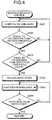
- FIG. 4 is a flowchart illustrating the light emission balance control process performed by the light emission balance controller according to the first embodiment.
- the WB coefficient calculation unit 407a acquires the WB coefficients (gains) and computes the gain ratios (WB gain ratios) based on the WB coefficients of the respective colors (step S201). More specifically, for example, using the WB coefficient of the green signal value (G signal) as a standard (for example, one), the ratios of the WB coefficients of the other colors are computed. After computing the WB gain ratios, the WB coefficient calculation unit 407a compares the WB gain ratio of the interest color and the WB gain threshold value, and determines whether the WB gain ratio is equal to or greater than the WB gain threshold value (step S202).
- FIG. 5 is a diagram explaining the WB gain ratio computation process of the light emission balance control process performed by the light emission balance controller of the endoscope system according to the first embodiment.
- the WB coefficient calculation unit 407a determines that the R gain ratio WB_R is greater than the WB gain threshold value WB_TH_R.
- WB_TH_R the WB gain threshold value
- the light emission balance controller 407 causes the color component comparison unit 407b to perform the process of comparing the detection value ratios (step S203).
- FIG. 6 is a diagram explaining the WB gain ratio computation process of the light emission balance control process performed by the light emission balance controller of the endoscope system according to the first embodiment.
- the WB coefficient calculation unit 407a determines that the R gain ratio WB_R is less than the WB gain threshold value WB_TH_R.
- the WB gain ratio of the interest color is less than the WB gain threshold value according to the WB coefficient calculation unit 407a, it can be determined that the sensitivity of the interest color is high.
- the WB coefficient calculation unit 407a determines that the WB gain ratio is less than the WB gain threshold value (step S202: No)
- the WB coefficient calculation unit 407a returns to step S201.
- FIG. 7 is a diagram explaining the detection value comparison process of the light emission balance control process performed by the light emission balance controller of the endoscope system according to the first embodiment.
- the color component comparison unit 407b acquires the detection values of the R signal, the G signal, and the B signal from the detection unit 402, computes the detection value ratios from the acquired detection values, and determines whether the detection value ratio of the interest color is greater than the detection threshold value. For example, when the interest color is red (R), and the detection value ratios illustrated in FIG. 7 are obtained, the color component comparison unit 407b determines that the R detection value ratio Y_R is greater than the detection threshold value Y_TH_R.
- the detection value ratio of the interest color is equal to or greater than the detection threshold value, it can be determined that the existence ratio of the interest color in the object is high.
- the color component comparison unit 407b determines that the detection value ratio of the interest color is equal to or greater than the detection threshold value (step S203: Yes)
- the light emission balance controller 407 causes the WB coefficient calculation unit 407a to perform the process of changing the WB gain ratio of the interest color (step S204).
- FIG. 8 is a diagram explaining the detection value comparison process of the light emission balance control process performed by the light emission balance controller of the endoscope system according to the first embodiment of the present invention.
- the color component comparison unit 407b determines that the R detection value ratio Y_R is less than the detection threshold value Y_TH_R.
- the detection value ratio of the interest color is less than the detection threshold value, it can be determined that the existence ratio of the interest color in the object is low.
- the color component comparison unit 407b determines that the detection value ratio of the interest color is less than the detection threshold value (step S203: No)
- the color component comparison unit 407b returns to step S201.
- the WB coefficient calculation unit 407a performs the process of changing the WB gain ratio of the interest color (WB gain ratio down process) (step S204).
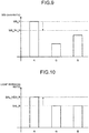
- FIG. 9 is a diagram explaining the WB gain ratio down process of the light emission balance control process performed by the light emission balance controller of the endoscope system according to the first embodiment.
- the WB coefficient calculation unit 407a reduces the WB gain ratio so that the gain ratio WB_R of the interest color is equal to the WB gain threshold value WB_TH_R.
- the WB coefficient calculation unit 407a calculates the WB coefficient based on the gain ratio subjected to the subtraction.
- FIG. 10 is a diagram explaining the light emission balance up process of the light emission balance control process performed by the light emission balance controller of the endoscope system according to the first embodiment.
- the light emission balance changing unit 407c changes a light emission ratio of the LED light source of the interest color. For example, when the interest color is red (R), as illustrated in FIG. 10 , the light emission ratio BAL_R of the red LED light source 311 before the change is increased to the light emission ratio BAL_NEW_R. In this case, the light emission balance changing unit 407c increases the light emission ratio by a preset amount.
- the light emission balance controller 407 instructs the illumination controller 32 to emit the illumination light using the new light emission ratio computed by the light emission balance changing unit 407c.
- the illumination controller 32 controls the red LED light source 311, the green LED light source 312, and the blue LED light source 313 to perform the control to emit the illumination light in the newly set light emission balance.
- the light emission balance controller 407 acquires the imaging signal (the R signal, the G signal, and the B signal) obtained through use of the new light emission ratio, and causes the color component comparison unit 407b to determine whether the detection value ratio of the interest color is fixed with respect to the detection value ratio before the change (step S206).
- the color component comparison unit 407b acquires the imaging signal (the R signal, the G signal, and the B signal) obtained through use of the new light emission ratio, computes the detection value ratios from the detection values that are based on the acquired imaging signal, and determines whether the detection value ratio of the interest color is fixed with respect to the detection value ratio before the change of the light emission ratio. For example, the color component comparison unit 407b determines whether the detection value ratio subjected to the change of the light emission ratio coincides with the detection value ratio Y_R illustrated in FIG. 7 . When it is determined by the color component comparison unit 407b that the detection value ratio of the interest color is fixed with respect to the detection value ratio before the change of the light emission ratio (step S206: Yes), the light emission balance controller 407 finishes the light emission balance control process.
- the imaging signal the R signal, the G signal, and the B signal
- step S206 when it is determined by the color component comparison unit 407b that the detection value ratio of the interest color is not fixed with respect to the detection value ratio before the change of the light emission ratio (step S206: No), the light emission balance controller 407 returns to step S205 and repeats the light emission balance up process.
- the initial light emission balance lighting in step S101 is performed at the time of starting the device (at the time of the first light emission control process).
- the initial light emission balance lighting may be performed, or whether the interest color is set or not may be confirmed without the initial light emission balance lighting, and the processes in step S103 and subsequent steps may be performed.
- the light emission balance controller 407 adjusts the light emission balance by increasing only the light emission ratio of the interest color based on the light emission balance control parameter (the WB gain threshold value and the detection threshold value) corresponding to the interest color. Therefore, the amount of heat generation can be suppressed, and the light quantity of the color component of interest can be increased.
- the WB coefficient of the interest color can be reduced, and the light quantity of the LED light source of the interest color can be increased so that the detection value ratio is fixed with respect to the detection value ratio before the change. Therefore, the WB coefficient can be reduced to suppress a factor of noise amplification, and the light quantity of only the specific color component can be increased.
- the light emission balance changing unit 407c may acquire the subtraction amount for the WB gain ratio from the WB coefficient calculation unit 407a and increase the light emission ratio in accordance with the subtraction amount.
- the first embodiment has been described on the premise that the AFE unit 231 has the function of the color separation unit. However, a color separation unit independent of the AFE unit 231 may be provided, or the color separation unit may be provided in the processing device 4.
- the first embodiment has been described on the premise that the connector unit 23b has the AFE unit 231 and the WB coefficient storage unit 232.
- the AFE unit 231 and the WB coefficient storage unit 232 may be provided in a proximal end part of the universal code 23 close to the operation 22 or provided in the operating unit 22.
- FIG. 11 is a view illustrating a schematic configuration of an endoscope system according to the second embodiment.
- FIG. 12 is a block diagram illustrating the schematic configuration of the endoscope system according to the second embodiment. Components identical to the above-mentioned components are provided with the same reference signs for illustration.
- an endoscope system la according to the second embodiment is configured such that a processing device 4a corresponding to the processing device 4 has an observation mode setting unit 409.
- the endoscope system 1a further includes a probe 6 capable of emitting a laser and a laser control device 7 connected to the probe 6 to supply laser light to the probe 6.
- the probe 6 and the laser control device 7 constitute a laser device.
- the observation mode setting unit 409 changes an observation mode in accordance with a signal input from the laser control device 7. More specifically, when the signal is not input from the laser control device 7, the observation mode is set to a normal observation mode, and the signal process or the like is performed in accordance with the configuration of the above-mentioned first embodiment. To the contrary, when the signal is input from the laser control device 7, the observation mode is set to a laser light observation mode, and the above-mentioned interest color is set to the color component corresponding to the wavelength band of the laser light, whereby the signal process or the like is performed.
- the probe 6 is inserted into the treatment tool insertion portion 222 of the endoscope 2 and comes out of the distal end portion 24.
- the inside of the probe 6 is provided with a fiber that guides the laser light and a lens or the like, and the probe 6 emits the laser light from the fiber through the lens or the like.
- a proximal end surface of the probe 6 is connected to a laser light emission surface of the laser control device 7. For example, an observed region within the body is irradiated with the laser light using the probe 6, whereby a treatment such as incision, blood stanching, clotting, and evaporation is performed on a living body tissue.
- the laser control device 7 has a laser light source 71, a light source driver 72, a drive controller 73, and an input unit 74.
- the laser light source 71 is realized with the use of a solid-state laser or a semiconductor laser.
- the light source driver 72 causes the laser light source 71 to emit the laser light by supplying a current to the laser light source 71 under the control of the drive controller 73.
- the drive controller 73 controls the laser light emitted by the laser control device 7 by controlling the light source driver 72 to turn on/off the laser light source 71.
- the drive controller 73 controls the timing for the light source driver 72 to supply power to the laser light source 71 based on an instruction signal from the input unit 74.
- the input unit 74 is realized with the used of, for example, a foot switch. When the foot switch is pressed, the input unit 74 accepts input of an instruction to emit the laser light and outputs the instruction signal to the drive controller 73 in accordance with the accepted input of the instruction.
- the laser control device 7 is also connected to the processing device 4a. For example, when the drive controller 73 controls the light source driver 72 to turn on the laser light source 71, the laser control device 7 inputs, to the processing device 4a, a signal indicating that the laser light source 71 is turned on.
- the observation mode setting unit 409 changes the observation mode from the normal observation mode to the laser light observation mode.
- a treatment is performed using the laser light, for example, in a case where the laser light containing light in a wavelength band included in the green wavelength band is used, an operator such as a medical doctor wears goggles that cut the light in the wavelength band of the laser light.
- the interest color is set to a color component other than the color component corresponding to the wavelength band of the laser light, the color component including the wavelength band of the laser light is controlled so as not to be settable as the interest color, or the LED light source corresponding to the color component including the wavelength band of the laser light is set to be turned off.
- a color matrix may be changed after the white balance process in accordance with the wavelength band of the laser light.
- the control unit 408 functions as a laser sensing unit.
- the operator may input a change instruction signal for the observation mode to the processing device 4a by pressing a switch allocated to the operating unit 22 or the like of the endoscope 2 in accordance with the input operation for the input unit 74, and the observation mode setting unit 409 may change the observation mode in accordance with the change instruction signal.
- the effect similar to that of the first embodiment is obtained, and the change of the interest color and the operation control for the LED light source are performed by changing the observation mode when the laser light is used. Therefore, when the laser light is used, the trouble of manually changing the observation mode by the operator is saved, unnecessary emission of the light in the wavelength band which is likely to be cut by the goggles or the like is suppressed, and light other than the light in the wavelength band which is likely to be cut is set as the interest color. Consequently, unnecessary procedures related to the observation with the use of the goggles can be eliminated, and a clearer observation can be performed.
- the first and second embodiments have been described on the premise that the red LED light source 311, the green LED light source 312, and the blue LED light source 313 are used as the light source unit 31a.
- an LED light source that emits light in a wavelength band other than red, green, and blue may be used, or a laser diode may be used as the light source.
- the imaging device and the processing device according to the present invention are useful for suppressing the amount of heat generation and increasing the light quantity of the color component of interest.
Landscapes
- Physics & Mathematics (AREA)
- Health & Medical Sciences (AREA)
- Life Sciences & Earth Sciences (AREA)
- Surgery (AREA)
- Engineering & Computer Science (AREA)
- Optics & Photonics (AREA)
- General Physics & Mathematics (AREA)
- Biomedical Technology (AREA)
- Veterinary Medicine (AREA)
- Pathology (AREA)
- Radiology & Medical Imaging (AREA)
- Biophysics (AREA)
- Nuclear Medicine, Radiotherapy & Molecular Imaging (AREA)
- Heart & Thoracic Surgery (AREA)
- Medical Informatics (AREA)
- Molecular Biology (AREA)
- Animal Behavior & Ethology (AREA)
- General Health & Medical Sciences (AREA)
- Public Health (AREA)
- Multimedia (AREA)
- Astronomy & Astrophysics (AREA)
- Signal Processing (AREA)
- Endoscopes (AREA)
- Instruments For Viewing The Inside Of Hollow Bodies (AREA)
Abstract
Description
- The present invention relates to an imaging device including an image sensor having a plurality of pixels and to a processing device connected to the imaging device.
- Conventionally, an endoscope system is used in the medical field when an organ of a subject such as a patient is observed. The endoscope system includes, for example, an endoscope, a light source device, and a processing device. The endoscope has an insertion portion provided with an image sensor at a distal end thereof, and the insertion portion is inserted into a body cavity of the subject. The light source device generates illumination light that is emitted from a distal end of the endoscope. The processing device performs an image process for an in-vivo image corresponding to an imaging signal generated by the image sensor and causes a display unit or the like to display the in-vivo image.
- In recent years, as a technique for adjusting a white balance of an image by means of illumination light, a shooting system including a light source unit having a red LED light source that emits light in a red wavelength band, a green LED light source that emits light in a green wavelength band, and a blue LED light source that emits light in a blue wavelength band has been disclosed (for example, refer to Patent Literature 1). In
Patent Literature 1, an object is illuminated with infrared light, and an image obtained by the illumination is subjected to a balance adjustment for RGB signals. Then, light intensity (light quantity) emitted by each of the red LED light source, the green LED light source, and the blue LED light source is individually changed in accordance with the balance, and the white balance of the image obtained by visible light is adjusted. - Patent Literature 1:
JP 2012-29728 A - Meanwhile, in an attempt to obtain an image in which a color that attracts attention during the observation is further clarified, a gain adjustment or a light quantity adjustment is performed on a signal of the color of interest. Since a noise component is also increased in the gain adjustment, the light quantity (luminance) of a color component of interest is preferably increased. However, the technique disclosed in
Patent Literature 1 only adjusts the light intensity of the light source of each color by performing the white balance adjustment before the observation, and ends up increasing the illumination light quantity while maintaining the balance of the RGB signals. Therefore, the light intensity of the light source of the color other than the interest color is also increased, and the amount of heat generation in the light source unit might be unnecessarily increased. - The present invention has been made in consideration of the above-mentioned circumstances, and an object thereof is to provide an imaging device and a processing device capable of suppressing the amount of heat generation in a light source unit and increasing the light quantity of a color component of interest.
- To solve the problem described above and to achieve the object, an imaging device according to the present invention includes: an imaging unit configured to capture an imaging object and output an imaging signal; an illumination unit including a plurality of light sources configured to emit respective beams of light of a plurality of colors different from one another; a color separation unit configured to separate the imaging signal into a plurality of signals corresponding to the plurality of colors; an interest color setting unit configured to set a color of interest as an interest color; and a light emission balance controller configured to control a light emission balance of the plurality of light sources by increasing a light quantity of the light source corresponding to the interest color set by the interest color setting unit based on the signal separated by the color separation unit.
- In the imaging device according to the present invention, the plurality of colors is red, green, and blue.
- The imaging device according to the present invention further includes a storage unit configured to store a first threshold value related to a light emission balance coefficient for adjusting a gain of a signal of each color in accordance with the light emission balance and a second threshold value related to a signal value of the color. The light emission balance controller includes: a light emission balance coefficient calculation unit configured to calculate a light emission balance coefficient of the color set by the interest color setting unit; a color component comparison unit configured to acquire the signal value of the color and compare existence ratios of the interest color and another color in the imaging signal; and a light emission balance changing unit configured to perform control to change the light emission balance in accordance with a calculation result provided by the light emission balance coefficient calculation unit, a determination result provided by the color component comparison unit, and the first and second threshold values stored in the storage unit.
- The imaging device according to the present invention further includes: a laser sensing unit configured to sense that laser light has been emitted from a laser device capable of emitting the laser light; and an observation mode changing unit configured to change an observation mode based on a sensing result provided by the laser sensing unit.
- A processing device according to the present invention is a processing device connected to an imaging device and a light source device, the imaging device including an imaging unit configured to capture an imaging object and output an imaging signal, the light source device including a plurality of light sources configured to emit respective beams of light of a plurality of colors different from one another, the processing device being configured to send and receive a signal between the imaging device and the light source device. The processing device includes: an interest color setting unit configured to set a color of interest as an interest color; and a light emission balance controller configured to control a light emission balance of the plurality of light sources by increasing a light quantity of the light source corresponding to the interest color set by the interest color setting unit based on separation signals into which the imaging signal has been separated in accordance with the plurality of colors.
- According to the present invention, the effect of being capable of suppressing the amount of heat generation and increasing the light quantity of a color component of interest can be obtained.
-
-
FIG. 1 is a view illustrating a schematic configuration of an endoscope system according to a first embodiment of the present invention. -
FIG. 2 is a block diagram illustrating the schematic configuration of the endoscope system according to the first embodiment of the present invention. -
FIG. 3 is a flowchart illustrating a light emission control process performed by the endoscope system according to the first embodiment of the present invention. -
FIG. 4 is a flowchart illustrating a light emission balance control process performed by a light emission balance controller of the endoscope system according to the first embodiment of the present invention. -
FIG. 5 is a diagram explaining a WB gain ratio computation process of the light emission balance control process performed by the light emission balance controller of the endoscope system according to the first embodiment of the present invention. -
FIG. 6 is a diagram explaining the WB gain ratio computation process of the light emission balance control process performed by the light emission balance controller of the endoscope system according to the first embodiment of the present invention. -
FIG. 7 is a diagram explaining a detection value comparison process of the light emission balance control process performed by the light emission balance controller of the endoscope system according to the first embodiment of the present invention. -
FIG. 8 is a diagram explaining a detection value comparison process of the light emission balance control process performed by the light emission balance controller of the endoscope system according to the first embodiment of the present invention. -
FIG. 9 is a diagram explaining a WB gain ratio down process of the light emission balance control process performed by the light emission balance controller of the endoscope system according to the first embodiment of the present invention. -
FIG. 10 is a diagram explaining a light emission balance up process of the light emission balance control process performed by the light emission balance controller of the endoscope system according to the first embodiment of the present invention. -
FIG. 11 is a view illustrating a schematic configuration of an endoscope system according to a second embodiment of the present invention. -
FIG. 12 is a block diagram illustrating the schematic configuration of the endoscope system according to the second embodiment of the present invention. - Hereinafter, embodiments for practicing the present invention (hereinafter referred to as "embodiments") will be described. In the embodiments, a medical endoscope system that captures and displays an image within a body cavity of a subject such as a patient is described as an example of a system including an imaging device and a processing device according to the present invention. The present invention is not limited by the embodiments. In the drawings, identical elements are provided with the same reference signs for illustration.
-
FIG. 1 is a view illustrating a schematic configuration of an endoscope system according to a first embodiment of the present invention.FIG. 2 is a block diagram illustrating the schematic configuration of the endoscope system according to the first embodiment. - An
endoscope system 1 illustrated inFIGS. 1 and2 includes anendoscope 2, a light source device 3, aprocessing device 4, and adisplay device 5. A distal end portion of theendoscope 2 is inserted into a body cavity of a subject, whereby theendoscope 2 captures an in-vivo image of the subject. The light source device 3 generates illumination light that is emitted from the distal end of theendoscope 2. Theprocessing device 4 performs a predetermined image process on the in-vivo image captured by theendoscope 2, and comprehensively controls operation of theentire endoscope system 1. Thedisplay device 5 displays the in-vivo image subjected to the image process by theprocessing device 4. - The
endoscope 2 includes aninsertion portion 21, anoperating unit 22, and auniversal code 23. Theinsertion portion 21 has a flexible elongated shape. Theoperating unit 22 is connected to a proximal end side of theinsertion portion 21 to accept input of various operation signals. Theuniversal code 23 extends from theoperating unit 22 in a direction different from a direction in which theinsertion portion 21 extends. Various cables connected to the light source device 3 and theprocessing device 4 are incorporated in theuniversal code 23. - The
insertion portion 21 has adistal end portion 24, acurve portion 25, and aflexible pipe portion 26. Animage sensor 244 is incorporated in thedistal end portion 24. In theimage sensor 244, pixels that receive light and perform a photoelectric conversion to generate signals are two-dimensionally arrayed. Thecurve portion 25 includes a plurality of curve pieces so as to be freely curved. Theflexible pipe portion 26 is connected to a proximal end side of thecurve portion 25 and has a flexible long shape. - The
distal end portion 24 includes alight guide 241, anillumination lens 242, anoptical system 243 for collecting light, and theimage sensor 244. Thelight guide 241 includes a glass fiber or the like, and serves as a light guide passage for the light emitted by the light source device 3. Theillumination lens 242 is provided at a distal end of thelight guide 241. Theimage sensor 244 is provided at an image forming position of theoptical system 243, receives the light collected by theoptical system 243, photoelectrically converts the light into an electric signal, and performs a predetermined signal process on the electric signal. - The
optical system 243 includes one or more lenses, and has an optical zoom function for changing an angle of view and a focus function for changing a focal point. - The image sensor 244 (imaging unit) photoelectrically converts the light from the
optical system 243 to generate the electric signal (imaging signal). More specifically, theimage sensor 244 has alight receiving unit 244a and areading unit 244b. In thelight receiving unit 244a, a plurality of pixels is arrayed in a matrix shape. Each of the plurality of pixels has, for example, a photodiode that accumulates a charge that depends on a light quantity and a capacitor that converts the charge transferred from the photodiode into a voltage level. Each pixel photoelectrically converts the light from theoptical system 243 to generate the electric signal. Thereading unit 244b reads the electric signal generated by each of the plurality of pixels of thelight receiving unit 244a, and outputs the electric signal as an imaging signal. A color filter is provided in each pixel of thelight receiving unit 244a. Therefore, each pixel receives light in a wavelength band transmitted through the color filter (for example, red light, green light, or blue light), and accumulates the charge that depends on the received light. Theimage sensor 244 controls various types of operation of thedistal end portion 24 in accordance with a drive signal received from theprocessing device 4. Theimage sensor 244 is realized with the use of, for example, a charge coupled device (CCD) image sensor or a complementary metal oxide semiconductor (CMOS) image sensor. - The operating
unit 22 has acurve knob 221, a treatmenttool insertion portion 222, and a plurality ofswitches 223. Thecurve knob 221 curves thecurve portion 25 in an up-down direction and a left-right direction. A treatment tool such as living body forceps, an electric scalpel, and an examination probe is inserted into the body cavity of the subject through the treatmenttool insertion portion 222. The plurality ofswitches 223 serves as an operation input unit through which an operation instruction signal for a peripheral device such as an air supply unit, a water supply unit, and screen display control as well as theprocessing device 4 and the light source device 3 is input. The treatment tool inserted through the treatmenttool insertion portion 222 passes through a treatment tool channel (not illustrated) of thedistal end portion 24 and comes out of an opening portion (not illustrated). - The
light guide 241 and an aggregatedcable 245 are at least incorporated in theuniversal code 23. One or more signal lines are bundled in the aggregatedcable 245. The aggregatedcable 245 includes a signal line for sending and receiving setting data, a signal line for sending and receiving the imaging signal, and a signal line for sending and receiving a drive timing signal for driving theimage sensor 244. - The
universal code 23 has aconnector unit 23a connected to the light source device 3 and aconnector unit 23b connected to theprocessing device 4. Theconnector unit 23b has anAFE unit 231 and a white balance (WB)coefficient storage unit 232. - The AFE unit 231 (color separation unit) has, for example, a noise reduction circuit, an automatic gain control (AGC) circuit, an A/D conversion circuit, and a color separation circuit. The noise reduction circuit reduces a noise component included in the analog imaging signal using a correlated double sampling (CDS) method. The AGC circuit adjusts an amplification factor (gain) of the electric signal to maintain a fixed output level. The A/D conversion circuit performs an A/D conversion on the imaging signal output through the AGC circuit. The color separation circuit separates the signal in accordance with color components of the color filters provided in the
light receiving unit 244a. For example, in a case where the color filters include red (R), green (G), and blue (B), the color separation circuit refers to the arrangement of the color filters and the pixels, and performs the separation into a red (R) signal, a green (G) signal, and a blue (B) signal (separation signals). TheAFE unit 231 performs the signal process on the imaging signal output from thereading unit 244b by means of the above-mentioned circuits, and thereafter outputs the imaging signal subjected to the signal process to theprocessing device 4. - The WB
coefficient storage unit 232 is realized with the use of a flash memory or the like. The WBcoefficient storage unit 232 stores a WB coefficient that is a coefficient for adjusting a white balance. The WB coefficient includes a plurality of coefficients by which the R signal, the G signal, and the B signal set in accordance with theimage sensor 244 are multiplied. For example, each coefficient computed at the time of calibration is stored as the WB coefficient. In addition, identification information related to the endoscope 2 (for example, unique information (ID), a model year, and specification information or the like of the endoscope 2) may be stored. - Next, a configuration of the light source device 3 will be described. The light source device 3 includes an
illumination unit 31 and anillumination controller 32. - Under the control of the
illumination controller 32, theillumination unit 31 sequentially switches between a plurality of beams of illumination light in different wavelength bands, and emits the plurality of beams of light to an object (subject). Theillumination unit 31 includes alight source unit 31a, alight source driver 31b, and amultiplexing lens 31c. - The
light source unit 31a includes a red LEDlight source 311, a green LEDlight source 312, and a blueLED light source 313 as well as one or more lenses or the like. Each LED light source emits light in the corresponding wavelength band under the control of thelight source driver 31b. The illumination light generated by thelight source unit 31a passes through thelight guide 241 and is emitted from a distal end of thedistal end portion 24 to the object. More specifically, thelight source unit 31a causes each of the red LEDlight source 311, the green LEDlight source 312, and the blueLED light source 313 to emit the light, whereby the light including the respective wavelength bands of the red light, the green light, and the blue light (for example, red: 600 nm to 700 nm, green: 500 nm to 600 nm, blue: 400 nm to 500 nm) is emitted as the illumination light. Consequently, theillumination unit 31 can sequentially emit any of the red light (R illumination), the green light (G illumination), and the blue light (B illumination) to theendoscope 2 by means of thelight source unit 31a (frame sequential method). - The
light source driver 31b causes thelight source unit 31a to emit the illumination light by supplying a current to each of the red LEDlight source 311, the green LEDlight source 312, and the blueLED light source 313 of thelight source unit 31a under the control of theillumination controller 32. - The multiplexing
lens 31c collects the beams of light in the respective wavelength bands emitted from the red LEDlight source 311, the green LEDlight source 312, and the blueLED light source 313, multiplexes the beams of light in these wavelength bands, and emits the light as the illumination light (for example, white light). - The
illumination controller 32 controls the wavelength band and the light quantity of the illumination light emitted by theillumination unit 31 by controlling thelight source driver 31b to turn on/off the red LEDlight source 311, the green LEDlight source 312, and the blueLED light source 313 of thelight source unit 31a. Based on a signal from theprocessing device 4, theillumination controller 32 controls the amount of power supplied by thelight source driver 31b to thelight source unit 31a (each LED light source), and controls the drive timing (light emission period) at which thelight source driver 31b drives thelight source unit 31a. - Next, a configuration of the
processing device 4 will be described. Theprocessing device 4 includes a white balance (WB)processing unit 401, adetection unit 402, animage processing unit 403, aninput unit 404, astorage unit 405, an interestcolor setting unit 406, a lightemission balance controller 407, and acontrol unit 408. - The
WB processing unit 401 performs a white balance adjustment on the R signal, the G signal, and the B signal included in the imaging signal output from the endoscope 2 (AFE unit 231), and outputs the imaging signal (the R signal, the G signal, and the B signal) subjected to the white balance adjustment to thedetection unit 402. More specifically, theWB processing unit 401 acquires, from the lightemission balance controller 407 or the WBcoefficient storage unit 232, the white balance coefficient for the signal of each color component, and multiplies the signal of each color component by the corresponding coefficient to perform the white balance adjustment. - The
detection unit 402 detects a signal value (luminance value of each pixel) after the white balance adjustment from each of the R signal, the G signal, and the B signal input from theWB processing unit 401, and outputs the signal value of each color component as a detection value. Thedetection unit 402 also outputs, to theimage processing unit 403, the imaging signal (the R signal, the G signal, and the B signal) subjected to the white balance adjustment and output from theWB processing unit 401. Thedetection unit 402 may output an average value of the luminance values of the identical color components as the detection value, or may output the maximum value, the minimum value, the most frequent value or the like as the detection value. - The
image processing unit 403 generates the in-vivo image that is displayed by thedisplay device 5 based on the imaging signal input from thedetection unit 402. Theimage processing unit 403 executes a predetermined image process on the imaging signal to generate an in-vivo image signal including the in-vivo image. Examples of the image process include a synchronization process, an optical black subtraction process, a white balance adjustment process, a color matrix calculation process, a gamma correction process, a color reproduction process, an edge enhancement process, a combining process for combining a plurality of pieces of image data, and a format conversion process or the like. - The
input unit 404 accepts input of various signals such as an instruction signal for giving an instruction for the operation of theendoscope system 1. - The
storage unit 405 is realized with the use of a semiconductor memory such as a flash memory and a dynamic random access memory (DRAM). Thestorage unit 405 stores data including, for example, various programs for operating theendoscope system 1 and various parameters required for the operation of theendoscope system 1. Thestorage unit 405 also stores identification information of theprocessing device 4. Examples of the identification information include unique information (ID), a model year, specification information, a transmission method, and a transmission rate or the like of theprocessing device 4. - The
storage unit 405 has a light emission balance controlparameter storage unit 405a that stores a WB gain threshold value (first threshold value) that is a threshold value of a ratio of the white balance coefficient of each color component and a detection threshold value of the detection value provided by the detection unit 402 (threshold value of a ratio of the signal value of each color, i.e. a second threshold value). The WB gain threshold values and the detection threshold values are set for the respective color components of the R signal, the G signal, and the B signal, and stored in the light emission balance controlparameter storage unit 405a. - The interest
color setting unit 406 sets a color of interest based on the instruction signal accepted by theinput unit 404. More specifically, the interestcolor setting unit 406 sets the interest color to red in response to the instruction signal for employing red as the interest color being input through theinput unit 404. - The light
emission balance controller 407 generates a control signal for driving each LED light source of thelight source unit 31a, and outputs the control signal to theillumination controller 32. The lightemission balance controller 407 has a WBcoefficient calculation unit 407a, a colorcomponent comparison unit 407b, and a light emissionbalance changing unit 407c. - The WB
coefficient calculation unit 407a calculates the WB coefficient of the color component set by the interestcolor setting unit 406 with reference to the WB gain threshold value stored in the light emission balance controlparameter storage unit 405a. More specifically, the WBcoefficient calculation unit 407a computes a gain ratio based on the WB coefficient of each color, compares the gain ratio with the WB gain threshold value, and reduces the gain ratio when the gain ratio of the interest color is greater than the WB gain threshold value. The WBcoefficient calculation unit 407a calculates the WB coefficient based on the gain ratio subjected to the subtraction. Consequently, the coefficient of the interest color related to the white balance is changed. The WBcoefficient calculation unit 407a outputs the WB coefficient subjected to the calculation to the WBcoefficient storage unit 232 and theWB processing unit 401. - The color
component comparison unit 407b acquires the detection values of the R signal, the G signal, and the B signal from thedetection unit 402, and compares existence ratios of the component of the interest color and the components of the other colors in the object (imaging signal). More specifically, the colorcomponent comparison unit 407b computes detection value ratios from the acquired detection values, acquires the detection threshold value of the interest color from the light emission balance controlparameter storage unit 405a, and determines whether the detection value ratio of the interest color is greater than the detection threshold value. The colorcomponent comparison unit 407b outputs, to the light emissionbalance changing unit 407c, the determination result associated with the detection value ratio of the interest color. - The light emission
balance changing unit 407c performs control to change a light emission balance in accordance with the calculation result of the WBcoefficient calculation unit 407a and the determination result of the colorcomponent comparison unit 407b. The light emissionbalance changing unit 407c changes the light quantity of the LED light source corresponding to the interest color when the light emissionbalance changing unit 407c determines to change the light emission balance with reference to the calculation result and the determination result. The light emissionbalance changing unit 407c outputs, to theillumination controller 32, a control signal for emitting the illumination light in the changed light emission balance. - The
control unit 408 includes a central processing unit (CPU) or the like, and performs drive control on the respective components including theendoscope 2 and the light source device 3 and information input/output control on the respective components. Thecontrol unit 408 sends the setting data for imaging control (for example, imaging timing or the like) stored in thestorage unit 405 to theimage sensor 244 through the predetermined signal line included in the aggregatedcable 245. - The
display device 5 receives and displays the in-vivo image corresponding to the in-vivo image signal generated by theprocessing device 4 through a video cable. Thedisplay device 5 includes liquid crystal or organic electro luminescence (EL). - In the first embodiment, the imaging device includes the
image sensor 244, theAFE unit 231, theillumination unit 31, theillumination controller 32, the interestcolor setting unit 406, and the lightemission balance controller 407. - Next, the light emission control performed by the
endoscope system 1 will be described with reference toFIG. 3. FIG. 3 is a flowchart illustrating the light emission control process performed by the endoscope system according to the first embodiment of the present invention. First, the lightemission balance controller 407 controls theillumination controller 32 to turn on the illumination light in an initial light emission balance (step S101). The initial light emission balance as used herein is a state free from the interest color setting of the interestcolor setting unit 406, namely, for example, a normal white balance adjusted to produce the white color. Theillumination controller 32 controls the light quantity emitted from each LED light source so that the white illumination light is produced in accordance with the normal white balance, and causes the illumination light to be emitted from the multiplexinglens 31c. - After that, the light
emission balance controller 407 determines whether the interest color is set by the interest color setting unit 406 (step S102). When the interest color is not set by the interest color setting unit 406 (step S102: No), the lightemission balance controller 407 returns to step S101 and performs the control to emit the illumination light in the normal white balance. - On the other hand, when the interest color is set by the interest color setting unit 406 (step S102: Yes), the light
emission balance controller 407 reads a light emission balance control parameter (the WB gain threshold value and the detection threshold value) corresponding to the interest color (step S103). - In response to reading the light emission balance control parameter, the light
emission balance controller 407 changes the light emission balance based on the read light emission balance control parameter, and controls theillumination controller 32 so that the illumination light is emitted in the changed light emission balance (step S104). - Next, the light emission balance control performed by the
endoscope system 1 will be described with reference toFIGS. 4 to 10 .FIG. 4 is a flowchart illustrating the light emission balance control process performed by the light emission balance controller according to the first embodiment. - In the light emission balance control process, first, the WB
coefficient calculation unit 407a acquires the WB coefficients (gains) and computes the gain ratios (WB gain ratios) based on the WB coefficients of the respective colors (step S201). More specifically, for example, using the WB coefficient of the green signal value (G signal) as a standard (for example, one), the ratios of the WB coefficients of the other colors are computed. After computing the WB gain ratios, the WBcoefficient calculation unit 407a compares the WB gain ratio of the interest color and the WB gain threshold value, and determines whether the WB gain ratio is equal to or greater than the WB gain threshold value (step S202). -
FIG. 5 is a diagram explaining the WB gain ratio computation process of the light emission balance control process performed by the light emission balance controller of the endoscope system according to the first embodiment. For example, when the interest color is red (R), and the WB gain ratios illustrated inFIG. 5 are obtained in step S201, the WBcoefficient calculation unit 407a determines that the R gain ratio WB_R is greater than the WB gain threshold value WB_TH_R. When the WB gain ratio of the interest color is equal to or greater than the WB gain threshold value, it can be determined that the sensitivity of the interest color is low. When it is determined by the WBcoefficient calculation unit 407a that the WB gain ratio of the interest color is equal to or greater than the WB gain threshold value (step S202: Yes), the lightemission balance controller 407 causes the colorcomponent comparison unit 407b to perform the process of comparing the detection value ratios (step S203). -
FIG. 6 is a diagram explaining the WB gain ratio computation process of the light emission balance control process performed by the light emission balance controller of the endoscope system according to the first embodiment. For example, when the interest color is red (R), and the WB gain ratios illustrated inFIG. 6 are obtained in step S201, the WBcoefficient calculation unit 407a determines that the R gain ratio WB_R is less than the WB gain threshold value WB_TH_R. When the WB gain ratio of the interest color is less than the WB gain threshold value according to the WBcoefficient calculation unit 407a, it can be determined that the sensitivity of the interest color is high. When the WBcoefficient calculation unit 407a determines that the WB gain ratio is less than the WB gain threshold value (step S202: No), the WBcoefficient calculation unit 407a returns to step S201. -
FIG. 7 is a diagram explaining the detection value comparison process of the light emission balance control process performed by the light emission balance controller of the endoscope system according to the first embodiment. In step S203, the colorcomponent comparison unit 407b acquires the detection values of the R signal, the G signal, and the B signal from thedetection unit 402, computes the detection value ratios from the acquired detection values, and determines whether the detection value ratio of the interest color is greater than the detection threshold value. For example, when the interest color is red (R), and the detection value ratios illustrated inFIG. 7 are obtained, the colorcomponent comparison unit 407b determines that the R detection value ratio Y_R is greater than the detection threshold value Y_TH_R. When the detection value ratio of the interest color is equal to or greater than the detection threshold value, it can be determined that the existence ratio of the interest color in the object is high. When the colorcomponent comparison unit 407b determines that the detection value ratio of the interest color is equal to or greater than the detection threshold value (step S203: Yes), the lightemission balance controller 407 causes the WBcoefficient calculation unit 407a to perform the process of changing the WB gain ratio of the interest color (step S204). -
FIG. 8 is a diagram explaining the detection value comparison process of the light emission balance control process performed by the light emission balance controller of the endoscope system according to the first embodiment of the present invention. For example, when the interest color is red (R), and the detection value ratios illustrated inFIG. 8 are obtained, the colorcomponent comparison unit 407b determines that the R detection value ratio Y_R is less than the detection threshold value Y_TH_R. When the detection value ratio of the interest color is less than the detection threshold value, it can be determined that the existence ratio of the interest color in the object is low. When the colorcomponent comparison unit 407b determines that the detection value ratio of the interest color is less than the detection threshold value (step S203: No), the colorcomponent comparison unit 407b returns to step S201. - Returning to the flowchart in
FIG. 4 , when it is determined that the WB gain ratio of the interest color is equal to or greater than the WB gain threshold value, and the detection value ratio of the interest color is equal to or greater than the detection threshold value, that is, when it is determined that the sensitivity of the interest color is low, and the existence ratio of the interest color in the object is high, the WBcoefficient calculation unit 407a performs the process of changing the WB gain ratio of the interest color (WB gain ratio down process) (step S204). -
FIG. 9 is a diagram explaining the WB gain ratio down process of the light emission balance control process performed by the light emission balance controller of the endoscope system according to the first embodiment. The WBcoefficient calculation unit 407a reduces the WB gain ratio so that the gain ratio WB_R of the interest color is equal to the WB gain threshold value WB_TH_R. The WBcoefficient calculation unit 407a calculates the WB coefficient based on the gain ratio subjected to the subtraction. - After the WB gain ratio down process performed by the WB
coefficient calculation unit 407a, the light emissionbalance changing unit 407c performs the process of changing the light emission balance (light emission balance up process) (step S205).FIG. 10 is a diagram explaining the light emission balance up process of the light emission balance control process performed by the light emission balance controller of the endoscope system according to the first embodiment. The light emissionbalance changing unit 407c changes a light emission ratio of the LED light source of the interest color. For example, when the interest color is red (R), as illustrated inFIG. 10 , the light emission ratio BAL_R of the red LEDlight source 311 before the change is increased to the light emission ratio BAL_NEW_R. In this case, the light emissionbalance changing unit 407c increases the light emission ratio by a preset amount. - After that, the light
emission balance controller 407 instructs theillumination controller 32 to emit the illumination light using the new light emission ratio computed by the light emissionbalance changing unit 407c. Theillumination controller 32 controls the red LEDlight source 311, the green LEDlight source 312, and the blueLED light source 313 to perform the control to emit the illumination light in the newly set light emission balance. The lightemission balance controller 407 acquires the imaging signal (the R signal, the G signal, and the B signal) obtained through use of the new light emission ratio, and causes the colorcomponent comparison unit 407b to determine whether the detection value ratio of the interest color is fixed with respect to the detection value ratio before the change (step S206). - The color
component comparison unit 407b acquires the imaging signal (the R signal, the G signal, and the B signal) obtained through use of the new light emission ratio, computes the detection value ratios from the detection values that are based on the acquired imaging signal, and determines whether the detection value ratio of the interest color is fixed with respect to the detection value ratio before the change of the light emission ratio. For example, the colorcomponent comparison unit 407b determines whether the detection value ratio subjected to the change of the light emission ratio coincides with the detection value ratio Y_R illustrated inFIG. 7 . When it is determined by the colorcomponent comparison unit 407b that the detection value ratio of the interest color is fixed with respect to the detection value ratio before the change of the light emission ratio (step S206: Yes), the lightemission balance controller 407 finishes the light emission balance control process. - On the other hand, when it is determined by the color
component comparison unit 407b that the detection value ratio of the interest color is not fixed with respect to the detection value ratio before the change of the light emission ratio (step S206: No), the lightemission balance controller 407 returns to step S205 and repeats the light emission balance up process. - When the above-mentioned light emission control process is performed, the initial light emission balance lighting in step S101 is performed at the time of starting the device (at the time of the first light emission control process). In the second and subsequent light emission control processes, the initial light emission balance lighting may be performed, or whether the interest color is set or not may be confirmed without the initial light emission balance lighting, and the processes in step S103 and subsequent steps may be performed.
- According to the above-mentioned first embodiment, the light
emission balance controller 407 adjusts the light emission balance by increasing only the light emission ratio of the interest color based on the light emission balance control parameter (the WB gain threshold value and the detection threshold value) corresponding to the interest color. Therefore, the amount of heat generation can be suppressed, and the light quantity of the color component of interest can be increased. - In addition, according to the above-mentioned first embodiment, owing to the above-mentioned light emission balance control process, the WB coefficient of the interest color can be reduced, and the light quantity of the LED light source of the interest color can be increased so that the detection value ratio is fixed with respect to the detection value ratio before the change. Therefore, the WB coefficient can be reduced to suppress a factor of noise amplification, and the light quantity of only the specific color component can be increased.
- The description has been provided on the premise that the light emission
balance changing unit 407c increases the light emission ratio by the preset amount. However, the light emissionbalance changing unit 407c may acquire the subtraction amount for the WB gain ratio from the WBcoefficient calculation unit 407a and increase the light emission ratio in accordance with the subtraction amount. - The first embodiment has been described on the premise that the
AFE unit 231 has the function of the color separation unit. However, a color separation unit independent of theAFE unit 231 may be provided, or the color separation unit may be provided in theprocessing device 4. - The first embodiment has been described on the premise that the
connector unit 23b has theAFE unit 231 and the WBcoefficient storage unit 232. However, theAFE unit 231 and the WBcoefficient storage unit 232 may be provided in a proximal end part of theuniversal code 23 close to theoperation 22 or provided in the operatingunit 22. - Next, a second embodiment of the present invention will be described.
FIG. 11 is a view illustrating a schematic configuration of an endoscope system according to the second embodiment.FIG. 12 is a block diagram illustrating the schematic configuration of the endoscope system according to the second embodiment. Components identical to the above-mentioned components are provided with the same reference signs for illustration. In comparison with the configuration of theendoscope system 1 according to the above-mentioned first embodiment, an endoscope system la according to the second embodiment is configured such that aprocessing device 4a corresponding to theprocessing device 4 has an observationmode setting unit 409. Theendoscope system 1a further includes aprobe 6 capable of emitting a laser and alaser control device 7 connected to theprobe 6 to supply laser light to theprobe 6. Theprobe 6 and thelaser control device 7 constitute a laser device. - The observation
mode setting unit 409 changes an observation mode in accordance with a signal input from thelaser control device 7. More specifically, when the signal is not input from thelaser control device 7, the observation mode is set to a normal observation mode, and the signal process or the like is performed in accordance with the configuration of the above-mentioned first embodiment. To the contrary, when the signal is input from thelaser control device 7, the observation mode is set to a laser light observation mode, and the above-mentioned interest color is set to the color component corresponding to the wavelength band of the laser light, whereby the signal process or the like is performed. - The
probe 6 is inserted into the treatmenttool insertion portion 222 of theendoscope 2 and comes out of thedistal end portion 24. The inside of theprobe 6 is provided with a fiber that guides the laser light and a lens or the like, and theprobe 6 emits the laser light from the fiber through the lens or the like. A proximal end surface of theprobe 6 is connected to a laser light emission surface of thelaser control device 7. For example, an observed region within the body is irradiated with the laser light using theprobe 6, whereby a treatment such as incision, blood stanching, clotting, and evaporation is performed on a living body tissue. - The
laser control device 7 has alaser light source 71, alight source driver 72, adrive controller 73, and an input unit 74. Thelaser light source 71 is realized with the use of a solid-state laser or a semiconductor laser. Thelight source driver 72 causes thelaser light source 71 to emit the laser light by supplying a current to thelaser light source 71 under the control of thedrive controller 73. Thedrive controller 73 controls the laser light emitted by thelaser control device 7 by controlling thelight source driver 72 to turn on/off thelaser light source 71. Thedrive controller 73 controls the timing for thelight source driver 72 to supply power to thelaser light source 71 based on an instruction signal from the input unit 74. The input unit 74 is realized with the used of, for example, a foot switch. When the foot switch is pressed, the input unit 74 accepts input of an instruction to emit the laser light and outputs the instruction signal to thedrive controller 73 in accordance with the accepted input of the instruction. - The
laser control device 7 is also connected to theprocessing device 4a. For example, when thedrive controller 73 controls thelight source driver 72 to turn on thelaser light source 71, thelaser control device 7 inputs, to theprocessing device 4a, a signal indicating that thelaser light source 71 is turned on. - In the
processing device 4a, in response to the signal being input from thelaser control device 7, the observationmode setting unit 409 changes the observation mode from the normal observation mode to the laser light observation mode. When a treatment is performed using the laser light, for example, in a case where the laser light containing light in a wavelength band included in the green wavelength band is used, an operator such as a medical doctor wears goggles that cut the light in the wavelength band of the laser light. In the laser light observation mode, therefore, the interest color is set to a color component other than the color component corresponding to the wavelength band of the laser light, the color component including the wavelength band of the laser light is controlled so as not to be settable as the interest color, or the LED light source corresponding to the color component including the wavelength band of the laser light is set to be turned off. Alternatively, a color matrix may be changed after the white balance process in accordance with the wavelength band of the laser light. In the second embodiment, thecontrol unit 408 functions as a laser sensing unit. - In a case where the
treatment device 4a and thelaser control device 7 are not connected to each other, for example, the operator may input a change instruction signal for the observation mode to theprocessing device 4a by pressing a switch allocated to the operatingunit 22 or the like of theendoscope 2 in accordance with the input operation for the input unit 74, and the observationmode setting unit 409 may change the observation mode in accordance with the change instruction signal. - According to the above-mentioned second embodiment, the effect similar to that of the first embodiment is obtained, and the change of the interest color and the operation control for the LED light source are performed by changing the observation mode when the laser light is used. Therefore, when the laser light is used, the trouble of manually changing the observation mode by the operator is saved, unnecessary emission of the light in the wavelength band which is likely to be cut by the goggles or the like is suppressed, and light other than the light in the wavelength band which is likely to be cut is set as the interest color. Consequently, unnecessary procedures related to the observation with the use of the goggles can be eliminated, and a clearer observation can be performed.
- The first and second embodiments have been described on the premise that the red LED
light source 311, the green LEDlight source 312, and the blueLED light source 313 are used as thelight source unit 31a. However, an LED light source that emits light in a wavelength band other than red, green, and blue may be used, or a laser diode may be used as the light source. - As described above, the imaging device and the processing device according to the present invention are useful for suppressing the amount of heat generation and increasing the light quantity of the color component of interest.
-
- 1, 1a ENDOSCOPE SYSTEM
- 2 ENDOSCOPE
- 3 LIGHT SOURCE DEVICE
- 4, 4a PROCESSING DEVICE
- 31 ILLUMINATION UNIT
- 31a LIGHT SOURCE UNIT
- 31b LIGHT SOURCE DRIVER
- 32 ILLUMINATION CONTROLLER
- 231 AFE UNIT
- 244 IMAGE SENSOR
- 244a LIGHT RECEIVING UNIT
- 244b READING UNIT
- 245 AGGREGATED CABLE
- 401 WHITE BALANCE (WB) PROCESSING UNIT
- 402 DETECTION UNIT
- 403 IMAGE PROCESSING UNIT
- 404 INPUT UNIT
- 405 STORAGE UNIT
- 405a LIGHT EMISSION BALANCE CONTROL PARAMETER STORAGE UNIT
- 406 INTEREST COLOR SETTING UNIT
- 407 LIGHT EMISSION BALANCE CONTROLLER
- 408 CONTROL UNIT
- 409 OBSERVATION MODE SETTING UNIT
Claims (5)
- An imaging device comprising:an imaging unit configured to capture an imaging object and output an imaging signal;an illumination unit including a plurality of light sources configured to emit respective beams of light of a plurality of colors different from one another;a color separation unit configured to separate the imaging signal into a plurality of signals corresponding to the plurality of colors;an interest color setting unit configured to set a color of interest as an interest color; anda light emission balance controller configured to control a light emission balance of the plurality of light sources by increasing a light quantity of the light source corresponding to the interest color set by the interest color setting unit based on the signal separated by the color separation unit.
- The imaging device according to claim 1, wherein
the plurality of colors is red, green, and blue. - The imaging device according to claim 1 or 2, further comprising a storage unit configured to store a first threshold value related to a light emission balance coefficient for adjusting a gain of a signal of each color in accordance with the light emission balance and a second threshold value related to a signal value of the color, wherein
the light emission balance controller includes:a light emission balance coefficient calculation unit configured to calculate a light emission balance coefficient of the color set by the interest color setting unit;a color component comparison unit configured to acquire the signal value of the color and compare existence ratios of the interest color and another color in the imaging signal; anda light emission balance changing unit configured to perform control to change the light emission balance in accordance with a calculation result provided by the light emission balance coefficient calculation unit, a determination result provided by the color component comparison unit, and the first and second threshold values stored in the storage unit. - The imaging device according to claim 1, further comprising:a laser sensing unit configured to sense that laser light has been emitted from a laser device capable of emitting the laser light; andan observation mode changing unit configured to change an observation mode based on a sensing result provided by the laser sensing unit.
- A processing device connected to an imaging device and a light source device, the imaging device including an imaging unit configured to capture an imaging object and output an imaging signal, the light source device including a plurality of light sources configured to emit respective beams of light of a plurality of colors different from one another, the processing device being configured to send and receive a signal between the imaging device and the light source device, the processing device comprising:an interest color setting unit configured to set a color of interest as an interest color; anda light emission balance controller configured to control a light emission balance of the plurality of light sources by increasing a light quantity of the light source corresponding to the interest color set by the interest color setting unit based on separation signals into which the imaging signal has been separated in accordance with the plurality of colors.
Applications Claiming Priority (2)
| Application Number | Priority Date | Filing Date | Title |
|---|---|---|---|
| JP2014183390 | 2014-09-09 | ||
| PCT/JP2015/074872 WO2016039227A1 (en) | 2014-09-09 | 2015-09-01 | Imaging device and processing device |
Publications (1)
| Publication Number | Publication Date |
|---|---|
| EP3192430A1 true EP3192430A1 (en) | 2017-07-19 |
Family
ID=55458976
Family Applications (1)
| Application Number | Title | Priority Date | Filing Date |
|---|---|---|---|
| EP15840814.6A Withdrawn EP3192430A1 (en) | 2014-09-09 | 2015-09-01 | Imaging device and processing device |
Country Status (5)
| Country | Link |
|---|---|
| US (1) | US10349027B2 (en) |
| EP (1) | EP3192430A1 (en) |
| JP (1) | JP6049945B2 (en) |
| CN (1) | CN107072506B (en) |
| WO (1) | WO2016039227A1 (en) |
Families Citing this family (8)
| Publication number | Priority date | Publication date | Assignee | Title |
|---|---|---|---|---|
| WO2016079768A1 (en) * | 2014-11-17 | 2016-05-26 | オリンパス株式会社 | Optical scanning-type endoscope device |
| WO2019026191A1 (en) * | 2017-08-01 | 2019-02-07 | オリンパス株式会社 | Image capture device and control method |
| JP7023643B2 (en) * | 2017-09-07 | 2022-02-22 | ソニー・オリンパスメディカルソリューションズ株式会社 | Medical observation device and medical observation system |
| JP7184657B2 (en) | 2019-01-24 | 2022-12-06 | 富士フイルム株式会社 | endoscope system |
| JP7112970B2 (en) * | 2019-01-24 | 2022-08-04 | 富士フイルム株式会社 | endoscope system |
| EP3920463B1 (en) * | 2019-01-30 | 2024-09-11 | Sony Group Corporation | Encryption device, encryption method |
| KR102658571B1 (en) | 2019-06-11 | 2024-04-19 | 에스케이하이닉스 주식회사 | Image sensing device and manufacturing method of the same |
| CN119919321B (en) * | 2025-03-31 | 2025-07-01 | 浙江优亿医疗器械股份有限公司 | Endoscopic imaging method, device, computer equipment and storage medium |
Family Cites Families (7)
| Publication number | Priority date | Publication date | Assignee | Title |
|---|---|---|---|---|
| JP2003135393A (en) * | 2001-10-30 | 2003-05-13 | Olympus Optical Co Ltd | Automatic adjusting method for endoscope system |
| JP4734074B2 (en) * | 2005-09-30 | 2011-07-27 | オリンパスメディカルシステムズ株式会社 | Endoscope device |
| JP4868976B2 (en) * | 2006-08-18 | 2012-02-01 | オリンパスメディカルシステムズ株式会社 | Endoscope device |
| JP5032347B2 (en) * | 2008-01-16 | 2012-09-26 | 株式会社トプコン | Ophthalmic imaging equipment |
| JP5507376B2 (en) | 2010-07-28 | 2014-05-28 | 三洋電機株式会社 | Imaging device |
| JP5623266B2 (en) * | 2010-12-17 | 2014-11-12 | 富士フイルム株式会社 | Endoscope light source device and endoscope system |
| CN103619234B (en) * | 2012-04-04 | 2017-03-01 | 奥林巴斯株式会社 | Light supply apparatuses |
-
2015
- 2015-09-01 WO PCT/JP2015/074872 patent/WO2016039227A1/en not_active Ceased
- 2015-09-01 CN CN201580048291.4A patent/CN107072506B/en active Active
- 2015-09-01 JP JP2016520720A patent/JP6049945B2/en active Active
- 2015-09-01 EP EP15840814.6A patent/EP3192430A1/en not_active Withdrawn
-
2017
- 2017-03-08 US US15/452,984 patent/US10349027B2/en active Active
Also Published As
| Publication number | Publication date |
|---|---|
| US20170180695A1 (en) | 2017-06-22 |
| US10349027B2 (en) | 2019-07-09 |
| CN107072506B (en) | 2019-08-02 |
| JP6049945B2 (en) | 2016-12-21 |
| CN107072506A (en) | 2017-08-18 |
| JPWO2016039227A1 (en) | 2017-04-27 |
| WO2016039227A1 (en) | 2016-03-17 |
Similar Documents
| Publication | Publication Date | Title |
|---|---|---|
| US10349027B2 (en) | Imaging device and processing device | |
| JP5452785B1 (en) | Imaging system | |
| JP5659315B2 (en) | Endoscope device | |
| US9414739B2 (en) | Imaging apparatus for controlling fluorescence imaging in divided imaging surface | |
| JP5467182B1 (en) | Imaging system | |
| JP5927370B1 (en) | Imaging apparatus and processing apparatus | |
| US20140036051A1 (en) | Medicine system | |
| EP2638846A1 (en) | Medical device | |
| WO2015093295A1 (en) | Endoscopic device | |
| JP5769892B2 (en) | Endoscope | |
| US20190133426A1 (en) | Electronic endoscope and endoscope system | |
| WO2016104386A1 (en) | Dimmer, imaging system, method for operating dimmer, and operating program for dimmer | |
| JP6109457B1 (en) | Imaging system and processing apparatus | |
| US20160066769A1 (en) | Imaging device | |
| JP2014183908A (en) | Imaging system | |
| JP6335776B2 (en) | Endoscope system | |
| WO2017022323A1 (en) | Image signal processing method, image signal processing device and image signal processing program |
Legal Events
| Date | Code | Title | Description |
|---|---|---|---|
| STAA | Information on the status of an ep patent application or granted ep patent |
Free format text: STATUS: THE INTERNATIONAL PUBLICATION HAS BEEN MADE |
|
| PUAI | Public reference made under article 153(3) epc to a published international application that has entered the european phase |
Free format text: ORIGINAL CODE: 0009012 |
|
| STAA | Information on the status of an ep patent application or granted ep patent |
Free format text: STATUS: REQUEST FOR EXAMINATION WAS MADE |
|
| 17P | Request for examination filed |
Effective date: 20170308 |
|
| AK | Designated contracting states |
Kind code of ref document: A1 Designated state(s): AL AT BE BG CH CY CZ DE DK EE ES FI FR GB GR HR HU IE IS IT LI LT LU LV MC MK MT NL NO PL PT RO RS SE SI SK SM TR |
|
| AX | Request for extension of the european patent |
Extension state: BA ME |
|
| DAV | Request for validation of the european patent (deleted) | ||
| DAX | Request for extension of the european patent (deleted) | ||
| STAA | Information on the status of an ep patent application or granted ep patent |
Free format text: STATUS: THE APPLICATION HAS BEEN WITHDRAWN |
|
| 18W | Application withdrawn |
Effective date: 20180614 |